

Page 1

Type 8012
Flowmeter with paddle-wheel
Durchfluss-Messgerät mit Flügelrad
Débitmètre à ailette
Operating Instructions
Bedienungsanleitung
Manuel d‘utilisation
Page 2

We reserve the right to make technical changes without notice.
Technische Änderungen vorbehalten.
Sous réserve de modifications techniques.
© 2009-2012 Bürkert SAS
Operating Instructions 1202/1_EU-ML_00563643_ORIGINAL_FR
Page 3

Type 8012
Table of Contents
1. ABOUT THIS MANUAL .................................................................................5
1.1. Symbols used .......................................................................................5
1.2. Definition of the word "device" ....................................................5
2. INTENDED USE ................................................................................................6
2.1. Restraints ................................................................................................6
3. BASIC SAFETY INFORMATION ...............................................................6
4. GENERAL INFORMATION ...........................................................................8
4.1. Manufacturer's address and international contacts .........8
4.2. Warranty conditions ...........................................................................8
4.3. Information on the Internet ............................................................8
5. DESCRIPTION ...................................................................................................8
5.1. Area of application .............................................................................8
5.2. General description ...........................................................................8
5.2.1. Construction ........................................................................... 8
5.2.2. Version with pulse output .................................................... 9
5.2.3. Version with pulse output and current output ..............10
5.3. Description of the name plate of the 8012 ........................ 11
5.4. Description of the name plate of the SE12 ...........................11
5.5. Order codes for the basic versions of the SE12
module ................................................................................................... 12
6. TECHNICAL DATA ........................................................................................14
6.1. Conditions of use ............................................................................. 14
6.2. Conformity to standards and directives...............................14
6.3. General technical data .................................................................. 14
6.3.1. Mechanical data ..................................................................14
6.3.2. General data .........................................................................21
6.3.3. Electrical data.......................................................................23
6.3.4. Electrical connections ........................................................23
6.3.5. K factors ................................................................................23
7. INSTALLATION AND WIRING .................................................................25
7.1. Safety instructions...........................................................................25
7.2. Installation onto the pipe ............................................................. 26
7.2.1. Recommendations for installing the 8012 on
the pipe ..................................................................................26
7.2.2. Installing a device with welding ends .............................28
7.2.3. Installing a device with Clamp connections ..................29
7.2.4. Installing a device with flange connections ...................29
7.3. Graphs ................................................................................................... 30
7.4. Electrical wiring .................................................................................31
7.4.1. Assembling the M12 female connector .........................32
7.4.2. Wiring a version with adjustable M12 fixed
English
3
Page 4

Type 8012
connector ..............................................................................32
7.4.3. Wiring a version with cable gland ...................................33
8. COMMISSIONING ........................................................................................ 35
8.1. Safety instructions...........................................................................35
9. ADJUSTMENT AND FUNCTIONS .........................................................35
9.1. Safety instructions...........................................................................35
9.2. Pulse output ........................................................................................35
9.2.1. Frequency proportional to a volume ...............................35
9.2.2. Switching function ..............................................................36
9.2.3. Detection of a change in the fluid direction (only
8012 with optical sensor) .................................................37
9.3. Current output ................................................................................... 39
9.3.1. Extension of the current range .........................................39
9.3.2. Conversion of the frequency into a flow rate ................39
9.3.3. Current attenuation variations ..........................................40
10. MAINTENANCE AND TROUBLESHOOTING ................................40
10.1. Safety instructions...........................................................................40
10.2. Cleaning ................................................................................................ 41
10.3. Replacing the seal ...........................................................................41
10.4. If you encounter problems ..........................................................42
10.4.1. Problems signalled by the LEDs ......................................42
10.4.2. Problems not signalled by the LEDs ...............................43
11. SPARE PARTS AND ACCESSORIES ............................................... 43
12. PACKAGING, TRANSPORT, STORAGE .......................................... 45
4
English
Page 5

Type 8012
Warns against material damage.
Failure to observe this warning may result in damage to the device
About this manual
1. ABOUT THIS MANUAL
This manual describes the entire life cycle of the device. Please keep
this manual in a safe place, accessible to all users and any new owners.
This manual contains important safety information.
Failure to comply with these instructions can lead to hazardous
situations.
• This manual must be read and understood.
1.1. Symbols used
danger
Warns against an imminent danger.
• Failure to observe this warning can result in death or in serious
injury.
Warning
Warns against a potentially dangerous situation.
• Failure to observe this warning can result in serious injury or even
death.
attention
Warns against a possible risk.
• Failure to observe this warning can result in substantial or minor
injuries.
note
•
or system.
indicates additional information, advice or important
recommendations.
refers to information contained in this manual or in other
documents.
→ Indicates a procedure to be carried out.
1.2. Definition of the word "device"
→ The word "device" used within this manual refers to the flow-
meter type 8012.
English
5
Page 6

Type 8012
Intended use
2. INTENDED USE
Use of the flowmeter that does not comply with the instructions could present risks to people, nearby installations and
the environment.
• The 8012 flowmeter is intended exclusively to measure flow rate
in liquids.
• This device must be protected against electromagnetic interference, ultraviolet rays and, when installed outdoors, the effects
of climatic conditions.
• This device must be used in compliance with the characteristics
and commissioning and use conditions specified in the contractual documents and in the user manual.
• Requirements for the safe and proper operation of the device
are proper transport, storage and installation, as well as careful
operation and maintenance.
• Only use the device as intended.
2.1. Restraints
Observe any existing restraints when the device is exported.
3. BASIC SAFETY INFORMATION
This safety information does not take into account:
• any contingencies or occurences that may arise during assembly,
use and maintenance of the devices.
• the local safety regulations that the operator must ensure the staff
in charge of installation and maintenance observe.
Danger due to high pressure in the installation.
Danger due to electrical voltage.
Danger due to high temperatures of the fluid.
Danger due to the nature of the fluid.
Various dangerous situations
To avoid injury take care:
• to prevent any unintentional power supply switch-on.
• to ensure that installation and maintenance work are
carried out by qualified, authorised personnel in possession of
the appropriate tools.
• to guarantee a defined or controlled restarting of the process,
after a power supply interruption.
6
English
Page 7

Type 8012
The device may be damaged by the fluid in contact with.
Elements / Components sensitive to electrostatic discharges
Intended use
note
Various dangerous situations
To avoid injury take care:
• to use the device only if in perfect working order and in compliance with the instructions provided in the instruction manual..
• to observe the general technical rules when installing and using
the device.
• not to use this device in explosive atmospheres.
• not to use the device for the measurement of gas flow rates.
• not to use fluid that is incompatible with the materials the device
is made of.
• not to use this device in an environment incompatible with the
materials it is made of.
• not to subject the device to mechanical loads (e.g. by placing
objects on top of it or by using it as a step).
• not to make any external modifications to the device. Do not paint
any part of the device.
note
• Systematically check the chemical compatibility of the component materials of the device and the fluids likely to come into
contact with it (for example: alcohols, strong or concentrated
acids, aldehydes, alkaline compounds, esters, aliphatic compounds, ketones, halogenated aromatics or hydrocarbons,
oxidants and chlorinated agents).
• This device contains electronic components sensitive to electrostatic discharges. They may be damaged if they are touched
by an electrostatically charged person or object. In the worst
case scenario, these components are instantly destroyed or go
out of order as soon as they are activated.
• To minimise or even avoid all damage due to an electrostatic
discharge, take all the precautions described in the EN 613405-1 and 5-2 norms.
• Also ensure that you do not touch any of the live electrical
components.
English
7
Page 8

Type 8012
General information
4. GENERAL INFORMATION
4.1. Manufacturer's address and international contacts
To contact the manufacturer of the device use following address:
Bürkert SAS
Rue du Giessen
BP 21
F-67220 TRIEMBACH-AU-VAL
You may also contact your local Bürkert sales office.
The addresses of our international sales offices can be found on the
last pages of this manual. They are also available on the Internet at:
www.burkert.com
4.2. Warranty conditions
The condition governing the legal warranty is the conforming use of
the 8012 in observance of the operating conditions specified in this
manual.
4.3. Information on the Internet
You can find the user manuals and technical data sheets regarding
the type 8012 at: www.burkert.com
5. DESCRIPTION
5.1. Area of application
The 8012 flowmeter with magnetic sensor is intended to measure the
flow rate of neutral or slightly aggressive liquids free of solid particles.
The 8012 flowmeter with optical sensor is intended exclusively for
measuring the flow rate of liquids that allow the passage of infrared rays.
5.2. General description
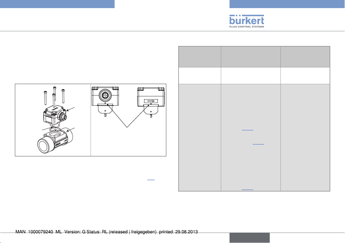
5.2.1. Construction
The 8012 flowmeter comprises the SE12 electronics incorporating
the measuring paddle-wheel and an S012 fitting allowing the device
to be fitted to all types of pipes from DN6 to DN65.
The sensor detects the rotation of the paddle-wheel; it generates a
signal in which the frequency f is proportional to the rotation frequency
of the paddle-wheel.
The electronic module is fitted with 2 LEDs visible by transparency on
the side of the housing:
• A green LED is on when the device is energized (the paddlewheel is not running) and then flashes proportionally to the
rotation frequency of the paddle-wheel.
• A red LED signals a malfunction of the flowmeter (see chap.
10.4.1).
8
English
Page 9
Type 8012
General information
Depending on the version, the electrical connection is made using a
1 m long cable or a multi-pin M12 fixed connector which position can
be adjusted.
Depending on the version, the device is equipped:
• with one pulse output
• or one pulse output and one 4-20 mA current output.
SE12
Paddle-wheel
S012
Location of the LEDs
(depending on the version)
5.2.2. Version with pulse output
On the 16 basic versions of the SE12 module (see chap. 5.5), the
NPN pulse output generates a signal with a frequency f proportional
to the rotation frequency of the paddle-wheel.
To obtain a flow rate Q, this frequency must be divided by a proportionality factor K according to the following formula:
Q = f/K
Table 1 : Characteristics of the pulse output
Characteristic
of the pulse
Possible configurations (on request)
output
Transistor wiring • NPN
• or PNP
Behaviour of the
output
• Frequency proportional to the rotation of
the paddle-wheel (see
above)
• or frequency proportional to a volume (see
chap. 9.2.1)
• or switching mode
(see chap. 9.2.2)
• or mode detecting the
immediate or delayed
change of circulation
direction of the fluid
(only on versions with
optical sensor) (see
chap. 9.2.3)
Pulse output of
the basic versions
NPN
Frequency proportional to the rotation
of the paddle-wheel
English
9
Page 10

Type 8012
mA
0
20
4
Q
Q =
(I - 4)
125
8K
General information
5.2.3. Version with pulse output and
current output
Pulse output
The characteristics of the pulse output are identical to those on a
version with pulse output only. See chap. 5.2.2.
Current output
The current output on the basic versions is connected in sink mode
and delivers a current I, an image of the rotation frequency f of the
paddle-wheel:
I = 8f/125 + 4
As f = KQ, the flow Q is therefore proportional to this current:
Q: flow rate [litre/s]
K: K factor [pulse/litre]
l: current [mA]
Flow rate
Current attenuation variations
When the flow varies quickly, the current output signal from your
device can be stabilised. On the basic versions, the current variations
are slightly attenuated.
Generation of an alarm current (versions with optical sensor
only)
On the basic versions, an "alarm" current of 22 mA is generated when
the circulation direction of the fluid is the opposite of the direction of
the arrow on the side of the housing.
10
English
Table 2 : Current output data
Characteristic Possible configurations (on
request)
Wiring • source
• or sink
Current output
range and associated measuring
range
• 4-20 mA, corresponding to
the rotation frequency range
0-250 Hz of the paddle-wheel
(see above)
• or 4-20 mA, corresponding to a
flow range, in the unit specific to
the application (see chap. 9.3.1)
• or 4-21.6 mA, corresponding
to the rotation frequency range
0-275 Hz of the paddle-wheel
(see chap. 9.3.1)
• or 4-21,6 mA, corresponding
to a flow range, in the unit
specific to the application (see
chap. 9.3.2)
Current attenuation variations
Ten possible attenuation levels:
ranging from "no attenuation" to
"maximum attenuation" (see chap.
9.3.3)
Configuration
on a basic
version
sink
4-20 mA, corresponding to
the 0-250 Hz
rotation
frequency
range of the
paddle-wheel
Slight attenuation of
the current
variations
Page 11

Type 8012
General information
5.3. Description of the name plate of the 8012
1
FLOW:8012 HALL
NPN/PNP : 0,7A - 36 VDC
12-36 VDC 4-20 mA
MS FKM 0,3-10 M/S
S-N:1092
Made in France
00557060 W47LE
1. Measured value and type of the device
2. Type of sensor
3. Characteristics of the pulse output
4. Type of current output
5. Flow range
6. Conformity logo
7. Manufacturing code
8. Materials the fitting and the seal in contact with the fluid are
made of
9. Serial number
10. Order code
11. Supply voltage
2
3
4
5
8 11 10
6 7 9
5.4. Description of the name plate of the SE12
1
FLOW:SE12 HALL
NPN/PNP : 0,7A - 36 VDC
12-36 VDC 4-20 mA
0,3-10 M/S
S-N:1092
Made in France
00557060 W47LE
1. Measured value and type of the device
2. Type of sensor
3. Characteristics of the pulse output
4. Type of current output
5. Flow range
6. Conformity logo
7. Manufacturing code
8. Serial number
9. Order code
10. Supply voltage
2
3
4
5
8 10
6 7 9
English
11
Page 12

Type 8012
General information
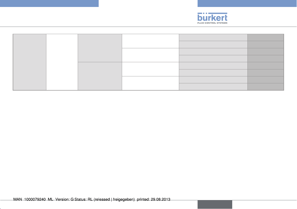
5.5. Order codes for the basic versions of the SE12 module
The fitting S012 is not available as a separate part.
Two versions of the S012 in DN15 and DN20 exist, having different K factors.
Only version 2, identified by the "v2" marking, is available from March 2012. The "v2" marking can be found:
V2
• on the bottom of the DN15 or DN20 fitting in plastic:
V2
• on the side of the DN15 or DN20 fitting in metal:
Supply
voltage
12-36 V DC Hall
12
Measurement
principle
Fitting Electrical connection Outputs Order code
DN6, DN8, DN15 v2
and DN20 v2
DN15 to DN65
(except DN15 v2
and DN20 v2)
English
Male 5-pin M12 fixed
connector
Cable gland, including 1 m
cable
Male 5-pin M12 fixed
connector
Cable gland, including 1 m
cable
Pulse, NPN 557054
Pulse, NPN + 4-20 mA 557058
Pulse, NPN 557056
Pulse, NPN + 4-20 mA 557060
Pulse, NPN 557053
Pulse, NPN + 4-20 mA 557057
Pulse, NPN 557055
Pulse, NPN + 4-20 mA 557059
Page 13
Type 8012
General information
12-36 V DC Optical
DN6, DN8, DN15 v2
and DN20 v2
DN15 to DN65
(except DN15 v2
and DN20 v2)
Male 5-pin M12 fixed
connector
Cable gland, including 1 m
cable
Male 5-pin M12 fixed
connector
Cable gland, including 1 m
cable
Pulse, NPN 557062
Pulse, NPN + 4-20 mA 557066
Pulse, NPN 557064
Pulse, NPN + 4-20 mA 557068
Pulse, NPN 557061
Pulse, NPN + 4-20 mA 557065
Pulse, NPN 557063
Pulse, NPN + 4-20 mA 557067
English
13
Page 14

Type 8012
Technical data
6. TECHNICAL DATA
6.1. Conditions of use
Ambient temperature -15 to +60 °C
Air humidity < 80%, non condensated
Protection rating • IP67 (version with M12 fixed
connector), female connector wired,
plugged in and tightened
• IP65 (version with cable gland)
6.2. Conformity to standards and directives
The device conforms to the EC directives through the following
standards:
• EMC : EN 61000-6-2, EN 61000-6-3
• Safety: EN 61 010-1
• Vibration: EN 60068-2-6
• Shock: EN 60068-2-27
• Pressure (S012 fitting of DN06 to DN65 in PP, PVC, PVDF, brass
or stainless steel): the device can only be used in the following
cases (depending on the max. pressure, the DN of the pipe and
the fluid)
Type of fluid Conditions
Fluid group 1, par. 1.3.a DN ≤ 25 only
Type of fluid Conditions
Fluid group 2 par. 1.3.a
Fluid group 1 par. 1.3.b PNxDN ≤ 2000
Fluid group 2 par. 1.3.b DN ≤ 200
DN ≤ 32
or DN > 32 and PNxDN ≤ 1000
6.3. General technical data
6.3.1. Mechanical data
Component Material
SE12 electronic housing PPS
Cable gland, M12 fixed
connector
Cable, 1 m PVC, T
Seal exposed to the fluid FKM (EDPM on request)
Seal exposed to the ambient air EDPM
Paddle-wheel holder PVDF
Paddle-wheel PVDF
Paddle-wheel axis and
bearings
Body of the S012 fitting
Screws Stainless steel A4
PA
= 80 °C
max
ceramic
stainless steel (316L/DIN1.4404),
brass, PVC, PP, PVDF
14
English
Page 15

Type 8012
D
Technical data
Cable
L = 1 m
68
69
46
40
50
35
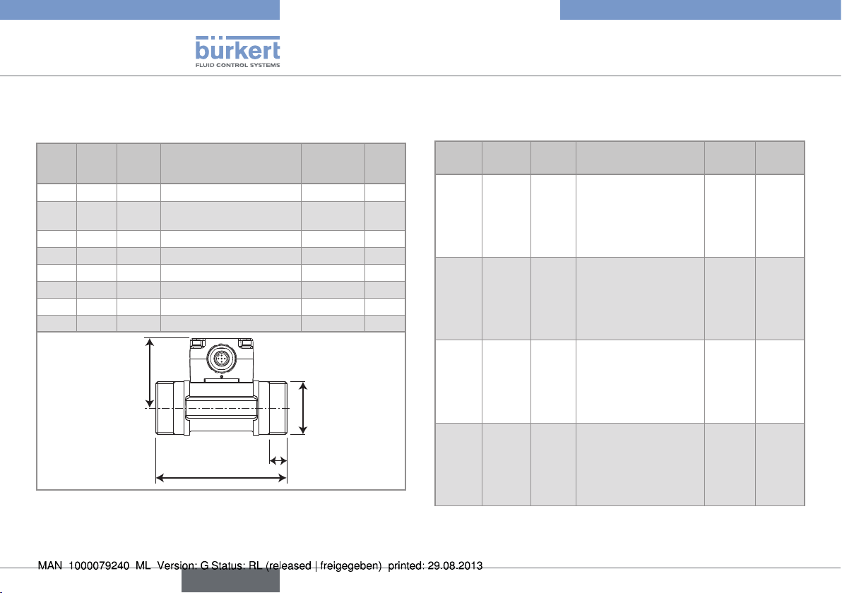
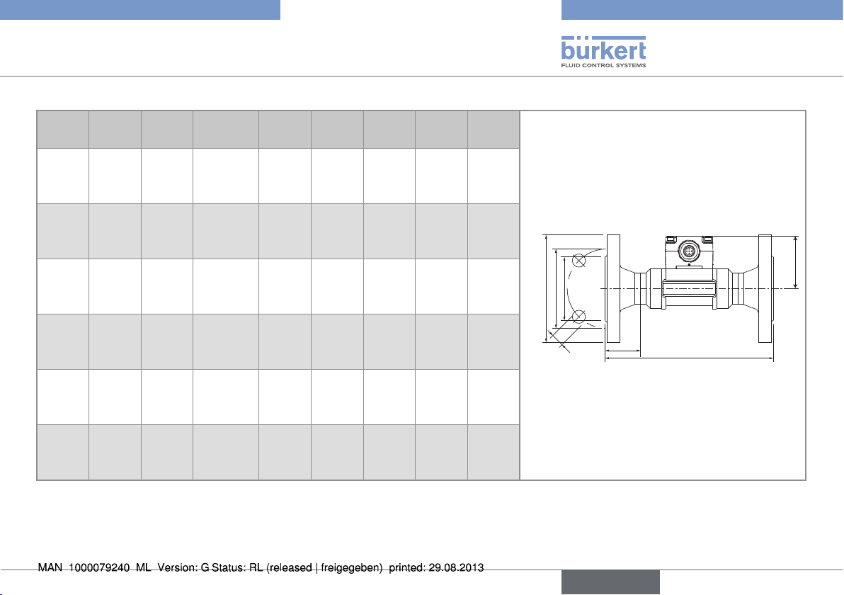
Fig. 1 : Dimensions of the SE12 module
Table 3 : Dimensions of the 8012 with internal thread connections
acc. to G, Rc, NPT, in stainless steel or brass
DN [mm] P [mm] A [mm] D [inch] L [mm]
15 57.5 84.0 G 1/2
NPT 1/2
Rc 1/2
20 55.0 94.0 G 3/4
NPT 3/4
Rc 3/4
25 55.2 104.0 G 1
NPT 1
Rc 1
32 58.8 119.0 G 1 3/4
NPT 1 3/4
Rc 1 3/4
40 62.6 129.0 G 1 1/2
NPT 1 1/2
Rc 1 1/2
16.0
17.0
15.0
17.0
18.3
16.3
23.5
18.0
18.0
23.5
21.0
21.0
23.5
20.0
19.0
50 68.7 148.5 G 2
NPT 2
Rc 2
27.5
24.0
24.0
P
D
L
A
Table 4 : Dimensions of the 8012 with external thread
connections acc. to SMS 1145, in stainless steel
DN [mm] P [mm] A [mm] D [inch]
25 55.0 130 Rd40 x 1/6"
40 58.8 164 Rd60 x 1/6"
50 62.6 173 Rd70 x 1/6"
P
A
English
15
Page 16
Type 8012
Technical data
Table 5 : Dimensions of the 8012 with external thread
connections acc. to G, Rc, NPT, in stainless steel, brass,
PVC or PVDF
DN
[mm]P[mm]A[mm]D[inch] [mm]
6 52.5 90.0 G 1/4 or G 1/2 - 14.0
8 52.5 90.0 G 1/2 or NPT 1/2 or
Rc 1/2
15 57.5 84.0 G 3/4 - 11.5
20 55.0 94.0 G 1 - 13.5
25 55.2 104.0 G 1 1/4 - 14.0
32 58.8 119.0 G 1 1/2 - 18.0
40 62.6 129.0 - M55 x 2 19.0
50 68.7 148.5 - M64 x 2 20.0
M16 x 1.5 14.0
L
[mm]
P
D
L
A
Table 6 : Dimensions of the 8012 with welding end connections
acc. to EN ISO 1127/ISO 4200, SMS 3008, BS 4825/
ASME BPE and DIN 11850 Rg2, in stainless steel
DN
[mm]P[mm]A[mm]
8 -
-
-
52.5
15 57.5
-
-
57.5
20 55.0
-
57.5
57.5
25 55.2
55.0
55.0
55.0
-
-
-
90.0
84.0
-
-
84.0
94.0
-
84.0
84.0
104.0
94.0
94.0
94.0
Standard
EN ISO 1127 / ISO
4200
SMS 3008
ASME BPE
DIN 11850 Rg2
EN ISO 1127 / ISO
4200
SMS 3008
ASME BPE
DIN 11850 Rg2
EN ISO 1127 / ISO
4200
SMS 3008
ASME BPE
DIN 11850 Rg2
EN ISO 1127 / ISO
4200
SMS 3008
ASME BPE
DIN 11850 Rg2
D
[mm]s[mm]
-
-
-
13.00
21.30
-
-
19.00
26.90
-
19.05
23.00
33.70
25.00
25.40
29.00
-
-
-
1.50
1.60
-
-
1.50
1.60
-
1.65
1.50
2.00
1.20
1.65
1.50
16
English
Page 17

Type 8012
Technical data
32 58.8
-
55.2
55.2
40 62.6
58.8
58.8
58.8
50 68.7
62.6
62.6
62.6
65 -
68.7
68.7
-
119.0
-
104.0
104.0
129.0
119.0
119.0
119.0
148.5
128.0
128.0
128.0
-
147.0
147.0
-
EN ISO 1127 / ISO
4200
SMS 3008
ASME BPE
DIN 11850 Rg2
EN ISO 1127 / ISO
4200
SMS 3008
ASME BPE
DIN 11850 Rg2
EN ISO 1127 / ISO
4200
SMS 3008
ASME BPE
DIN 11850 Rg2
EN ISO 1127 / ISO
4200
SMS 3008
ASME BPE
DIN 11850 Rg2
42.40
-
32.00
35.00
48.30
38.00
38.10
41.00
60.30
51.00
50.80
53.00
-
63.50
63.50
-
2.00
-
1.65
1.50
2.00
1.20
1.65
1.50
2.60
1.20
1.65
1.50
-
1.60
1.65
-
s
P
D
A
Table 7 : Dimensions of the 8012 with Clamp connections acc.
to ISO (for pipes acc. to EN ISO 1127 / ISO 4200),
SMS 3017 / ISO 2852 1), BS 4825 / ASME BPE 1) and
1)
Available with an internal surface finish of Ra = 0.8 μm
DN
[mm]P[mm]A[mm]
8 -
DIN 32676, in stainless steel
Standard
-
-
52.5
-
-
-
125
ISO (pipe EN ISO
1127 / ISO 4200)
SMS 3017/ISO 2852
ASME BPE
DIN 32676
D2
[mm]D1[mm]D[mm]
-
-
-
-
-
-
-
-
-
10.00
27.5
34.0
English
17
Page 18
Type 8012
Technical data
15 57.5
-
-
52.5
20 55.0
-
57.5
57.5
25 55.2
55.0
55.0
55.0
32 58.8
-
-
-
130.0
ISO (pipe EN ISO
1127 / ISO 4200)
-
SMS 3017/ISO 2852
-
ASME BPE
119.0
DIN 32676
150.0
ISO (pipe EN ISO
1127 / ISO 4200)
-
SMS 3017/ISO 2852
119.0
ASME BPE
119.0
DIN 32676
160.0
ISO (pipe EN ISO
1127 / ISO 4200)
129.0
SMS 3017/ISO 2852
129.0
ASME BPE
136.0
DIN 32676
180.0
ISO (pipe EN ISO
1127 / ISO 4200)
-
SMS 3017/ISO 2852
-
ASME BPE
-
DIN 32676
18.10
-
-
16.00
23.70
-
15.75
20.00
29.70
22.60
22.10
26.00
38.4
-
-
-
27.5
-
-
27.5
43.5
-
19.6
27.5
43.5
43.5
43.5
43.5
43.5
-
-
-
34.0
-
-
34.0
50.5
-
25.0
34.0
50.5
50.5
50.5
50.5
50.5
-
-
-
40 62.6
58.8
58.8
58.8
50 68.7
62.6
62.6
62.6
65 -
68.7
68.7
-
P
200.0
ISO (pipe EN ISO
1127 / ISO 4200)
161.0
SMS 3017/ISO 2852
161.0
ASME BPE
161.0
DIN 32676
230.0
ISO (pipe EN ISO
1127 / ISO 4200)
192.0
SMS 3017/ISO 2852
192.0
ASME BPE
170.0
DIN 32676
-
ISO (pipe EN ISO
1127 / ISO 4200)
216.0
SMS 3017/ISO 2852
216.0
ASME BPE
-
DIN 32676
44.3
35.6
34.8
38.0
55.1
48.6
47.5
50.0
-
60.3
60.2
-
56.5
43.5
43.5
43.5
70.5
56.5
56.5
56.5
-
70.5
70.5
-
D2
D1
64.0
50.5
50.5
50.5
77.5
64.0
64.0
64.0
-
77.5
77.5
-
D
18
A
English
Page 19
Type 8012
Technical data
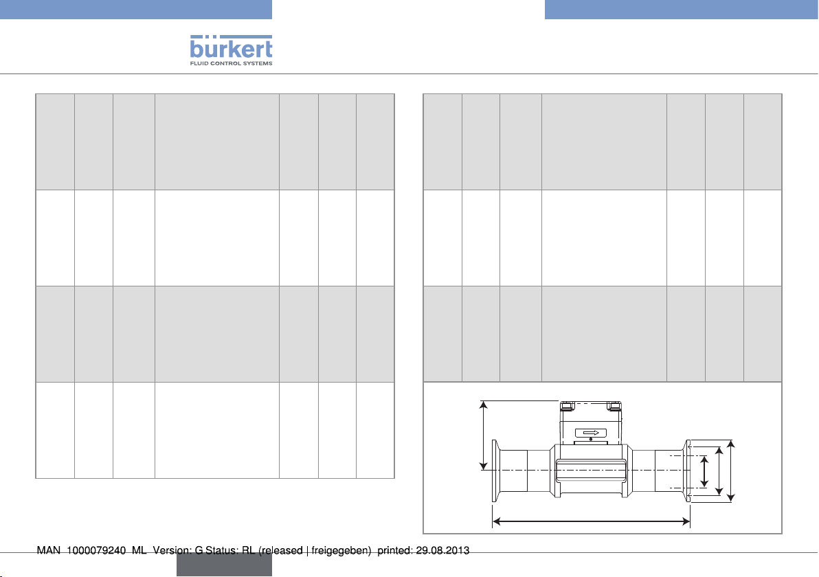
Table 8 : Dimensions of the 8012 with flange connections acc. to EN 1092-1 (ISO PN16), ANSI B16-5-1988 and JIS 10K, in stainless steel
DN
L
Standard
[mm]P[mm]A[mm]
15 57.5
57.5
57.5
20 55.0
55.0
55.0
25 55.2
55.2
55.2
32 58.8
58.8
58.8
40 62.6
62.6
62.6
50 68.7
68.7
68.7
130.0
130.0
152.0
150.0
150.0
178.0
160.0
160.0
216.0
180.0
180.0
229.0
200.0
200.0
241.0
230.0
230.0
267.0
DIN
ANSI
JIS
DIN
ANSI
JIS
DIN
ANSI
JIS
DIN
ANSI
JIS
DIN
ANSI
JIS
DIN
ANSI
JIS
[mm]Z[mm]D2[mm]D1[mm]D[mm]
23.5
23.5
23.5
28.5
28.5
28.5
28.5
28.5
28.5
31.0
31.0
31.0
36.0
36.0
36.0
41.0
41.0
41.0
4x14.0
4x15.8
4x15.0
4x14.0
4x15.8
4x15.0
4x14.0
4x15.8
4x19.0
4x18.0
4x15.8
4x19.0
4x18.0
4x15.8
4x19.0
4x18.0
4x19.0
4x19.0
45.0
34.9
51.0
58.0
42.9
56.0
68.0
50.8
67.0
78.0
63.5
76.0
88.0
73.0
81.0
102.0
92.1
96.0
65.0
60.3
70.0
75.0
69.8
75.0
85.0
79.4
90.0
100.0
88.9
100.0
110.0
98.4
105.0
125.0
120.6
120.0
95.0
89.0
95.0
105.0
99.0
100.0
115.0
108.0
125.0
140.0
117.0
135.0
150.0
127.0
140.0
165.0
152.0
155.0
D
D2
D1
Z
L
A
P
English
19
Page 20

Type 8012
H
A
Technical data
Table 9 : Dimensions of the 8012 with true union connections acc. to DIN 8063, ASTM D 1785/76 and JIS K in PVC, acc. to DIN 16962
in PP or acc. to ISO 10931 in PVDF
DN
[mm]P[mm]D[mm]
8* 29.5 31 122 - - 12 - - 90 92
15 34.5 43 128 130.0 129 20 21.3 18.40 90 96
20 32.0 53 144 145.6 145 25 26.7 26.45 100 106
25 32.2 60 160 161.4 161 32 33.4 32.55 110 116
32 35.8 74 168 170.0 169 40 42.2 38.60 110 116
40 39.6 83 188 190.2 190 50 48.3 48.70 120 127
50 45.7 103 212 213.6 213 63 60.3 60.80 130 136
* Only PVC
Table 10 : Dimensions of the 8012 with spigot connections acc. to DIN 8063 in PVC, acc. to DIN 16962 in PP or acc. to ISO 10931 in
PVDF
DN
[mm]
15 20 17.5 90 85 16.5 14 57.5
20 25 17.5 100 92 20 16 55.0
25 32 21.5 110 95 23 18 55.2
32 40 27.5 110 100 27.5 20 58.8
40 50 31.5 120 106 30 23 62.6
50 63 39.5 130 110 37 27 68.7
D
[mm]
A
DIN/ISO
H
[mm]
ASTM JIS
A [mm]
DIN 8063 DIN 16962
ISO 10931
D1
ASTM JIS
DIN/ISO
L [mm]
DIN 8063 DIN 16962
ISO 10931
A2
[mm]A1[mm]
P
P
D1
A2
A1
A
P
D
L
D
20
English
Page 21

Technical data
6.3.2. General data
Type 8012
Pipe diameter
Connections Material
Internal threads Stainless steel
External threads Stainless steel acc. to SMS
Welding ends Stainless steel
Clamp Stainless steel
True union PVC
Flanges Stainless steel
Spigot PVC
DN6 to DN65, depending on the design:
(the appropriate diameter is determined using the flow/DN/fluid velocity diagrams in chap. 7.3).
Brass
1145
Others
PP
PP
6 8 15 20 25 32 40 50 65
Available DN
- - yes yes yes yes yes yes -
- - - - yes - yes yes -
yes yes yes yes yes yes yes yes -
- yes yes yes yes yes yes yes yes
- yes yes yes yes yes yes yes yes
- yes yes yes yes yes yes yes -
- - yes yes yes yes yes yes -
- - yes yes yes yes yes yes -
- - yes yes yes yes yes yes -
English
21
Page 22

Type 8012
Technical data
Type of fluid
transparent to infrared rays
(optical sensor)
Max. temperature
of the fluid
Fitting in stainless steel, brass, PVDF:
a) 100 °C if the ambient temperature ≤ +45 °C
b) 90 °C if the ambient temperature is
between 45 °C and 60 °C
Fitting in PP: 80 °C
Fitting in PVC: 60 °C
Min. fluid
temperature
Fitting in stainless steel, brass: -15 °C
Fitting in PP or PVC: +5 °C
Fitting in PVDF: -15 °C
Fluid pressure
depends on the fitting material; see the
pressure / temperature diagramme in chap.
7.1
Fluid viscosity 300 cSt max.
Rate of solid
1% max.
particles
Measurement
0.3 m/s to 10 m/s (depending on the fitting)
range
Measurement
accuracy
≤ ± (0.5% of the full scale (10 m/s) + 2.5%
of the measured value), with standard K
factor
Linearity
≤
±0.5 % of the full scale (10 m/s)
Repeatability 0.4% of the measured value
Max. error [%]
10
8
6
4
2
1 9 2 3 4 5 6 7 8 10
-2
-4
-6
-8
-10
Velocity of fluid [m/s]
Typical Bürkert
curve
With standard K
factor (no calibration on site)
Fig. 2 : Measurement accuracy. These values were determined in
the following reference conditions:
medium = water, water and ambient temperatures 20 °C,
min. upstream and downstream distances respected,
appropriate pipe dimensions
Measuring
element
22
magnetic or optical sensor
English
Page 23

Type 8012
Technical data
6.3.3. Electrical data
Power supply 12-36 V DC, filtered and regulated
Current consumption
Protection against
polarity reversal
Protection against
spike voltages
Protection against
short circuits
Pulse output
Current output
(depending on
version)
• max. loop
impedance
max. 60 mA (at 12 V DC for the version
with current output - no load)
yes
yes
yes, for the pulse output
transistor, NPN by default (can be configured as PNP, on request), open collector,
700 mA max., NPN output: 0,2-36 V DC
and PNP output: supply voltage, frequency
up to 300 Hz (frequency = K factor x flow
rate). Configurable on request
4-20 mA, sinking wiring by default, equals
the rotation frequency of the paddle-wheel
(by default). Configurable on request
• 1125 W at 36 V DC
• 650 W at 24 V DC
• 140 W at 12 V DC
6.3.4. Electrical connections
Version Type
With a cable gland Cable, 1 m
With a fixed
connector
5-pin M12 fixed connector, adjustable in
position
6.3.5. K factors
The K factors have all been determined in the following reference
conditions:
medium = water, water and ambient temperatures 20 °C, min. upstream
and downstream distances respected, appropriate pipe dimensions
Two versions of the S012 in DN15 and DN20 exist, having
different K factors.
Only version 2, identified by the "v2" marking, is available
from March 2012. The "v2" marking can be found:
• on the bottom of the DN15 or DN20 fitting in plastic:
V2
• on the side of the DN15 or DN20 fitting in metal:
V2
English
23
Page 24

Type 8012
Technical data
Material Type of connections and standard
Stainless
steel
welding ends
• acc. to SMS 3008
• acc. to BS 4825 / ASME BPE
• acc. to EN ISO 1127 / ISO 4200
• acc. to DIN 11850 Rg2
Stainless
steel
external threads
• acc. to SMS 1145
• G
Stainless
steel
Stainless
steel
internal threads
• G, Rc, NPT
Clamp
• acc.to SMS 3017/ ISO 2852
• acc. to BS 4825 / ASME BPE
• acc. to ISO (for pipes acc. to
EN ISO 1127 / ISO 4200)
• acc. to DIN 32676
Stainless
steel
flanges
• acc. to EN1092-1 (ISO PN16)
• acc. to ANSI B16-5-1998
K factor [pulse/litre]
DN6 DN8 DN15 DN15 v2 DN20 DN20 v2 DN25 DN32 DN40 DN50 DN65
- - - - 97,0 73,4 61,5 47,5
- - - - 97,0 73,4 61,5 47,5
450 288
- 288
- - - - 97,0 73,4 61,5 47,5
450 288
450 288
- - - - 97,0 73,4 61,5 47,5
- - - - 97,0 73,4 61,5 47,5
450 288
- 288
450 288
1)
29.5 18.9 10.5
29.5 18.9 10.5
97,0 73,4 61,5 - 47,5 29,5 18,9 10,5 97,0 73,4 97,0 73,4 61,5 47,5
29.5 18.9 -
29.5 18.9 10.5
97,0 73,4 61,5 - 47,5 29,5 18,9 10,5 -
97,0 73,4 61,5 - 47,5 29,5 18,9 10,5 -
29.5 18.9 10.5
29.5 18.9 10.5
97,0 73,4 61,5 - 47,5 29,5 18,9 10,5 -
97,0 73,4 97,0 73,4 61,5 47,5
29.5 18.9 -
97,0 73,4 61,5 - 47,5 29,5 18,9 10,5 -
• acc. to JIS 10K
Brass all
450 288
97,0 73,4 61,5 - 47,5 29,5 18,9 10,5 -
PVC all 450 288 110 83,5 76,5 - 51,5 28,2 17,5 10,2 PP all - - 115 86,6 77,0 - 52,0 29,2 17,0 10,0 PVDF all 450 288 120 89,6 73,2 - 52,5 29,5 18,0 10,3 -
1)
K factor in pulse/US gallon = K factor in pulse/l x 3,785; K factor in pulse/UK gallon = K factor in pulse/l x 4,546
24
English
Page 25
Type 8012
Installation and wiring
7. INSTALLATION AND WIRING
7.1. Safety instructions
danger
Danger due to high pressure in the installation.
• Stop the circulation of fluid, cut off the pressure and drain the
pipe before loosening the process connections.
Danger due to electrical voltage.
• Shut down and isolate the electrical power source before carrying out work on the system.
• Observe all applicable accident protection and safety regulations for electrical equipment.
Danger due to high temperatures of the fluid.
• Use safety gloves to handle the device.
• Stop the circulation of fluid and drain the pipe before loosening
the process connections.
Danger due to the nature of the fluid.
• Respect the prevailing regulations on accident prevention and
safety relating to the use of aggressive fluids.
Warning
Risk of injury due to non-conforming installation.
• The electrical and fluid installation can only be carried out by
qualified and skilled staff with the appropriate tools.
• Install appropriate safety devices (correctly rated fuse and/or
circuit-breaker).
Risk of injury due to unintentional switch on of power supply
or uncontrolled restarting of the installation.
• Take appropriate measures to avoid unintentional activation of
the installation.
• Guarantee a defined or controlled restarting of the process
subsequent to the installation of the device.
Warning
Risk of injury if the fluid pressure/ temperature dependency
is not respected.
• Take the fluid pressure / temperature dependency into account
according to the nature of the material of the fitting used (see
Fig. 3Fig. ).
English
25
Page 26

T ( ° C)
Fluid pressure
When installing an 8012 with optical sensor:
Protect the device from strong light intensity to prevent any
Check that the DN of the fitting is dimensioned to the process
P (bar)
16
15
14
13
12
11
10
9
8
7
6
5
4
3
2
1
0
A
Metal (PN16)
PVDF
PVC + PP
PVDF (PN10)
PVC + PP
(PN10)
PP (PN10)
-20 0 +20 +40 +60 +80 +100 +120
Type 8012
Installation and wiring
7.2. Installation onto the pipe
danger
Danger due to high pressure in the installation.
• Stop the circulation of fluid, cut off the pressure and drain the
pipe before loosening the process connections.
Danger due to high temperatures of the fluid.
• Use safety gloves to handle the device.
• Stop the circulation of fluid and drain the pipe before loosening
the process connections.
Danger due to the nature of the fluid.
• Respect the prevailing regulations on accident prevention and
safety relating to the use of aggressive fluids.
7.2.1. Recommandations for installing the
8012 on the pipe
A : range of use for the complete device
Fig. 3 : Fluid pressure /temperature dependency curves
26
English
Fluid temperature
•
disruption of measurements.
• Ensure that the arrow on the side of the housing is in line
with the flow direction of the fluid.
according to the graphs in chap. 7.3.
Page 27

Type 8012
5 x DN
Installation and wiring
→ Install the device on the pipe in such a way that the upstream
and downstream distances are respected according to the
design of the pipes, as per Fig. 4 and the EN ISO 5167-1
standard.
50 x DN
5 x DN
With regulating valve
40 x DN
Pipe with 2 elbows at 90°
in 3 dimensions
at 90°
5 x DN
5 x DN
20 x DN
Pipe with 1 elbow at 90°
or 1 T-piece
15 x DN
25 x DN
Pipe with 2 elbows
18 x DN
With pipe expansion With pipe reduction
5 x DN
5 x DN
→ If necessary, use a flow conditioner to improve measurement
precision.
→ Install the device in such a way that the paddle-wheel axis is
horizontal (Fig. 5).
→ Prevent the formation of air bubbles in the pipe in the section
around the device (Fig. 6).
→ Ensure that the pipe is always filled in the section around the
device (Fig. 7).
Correct
Fig. 5 : The paddle-wheel axis must be horizontal
Incorrect
Fig. 4 : Upstream and downstream distances depending on the
design of the pipes.
English
27
Page 28

Correct
Fluid circulation
direction
Correct
Fig. 6 : Air bubbles within the pipe
Correct
Correct
Incorrect
Incorrect
Incorrect
Incorrect
Type 8012
Installation and wiring
7.2.2. Installing a device with welding
ends
note
The SE12 electronic module and the seal may be damaged
when welding the connections to the pipe.
• Before welding to the pipe, unscrew the 4 locking screws on
the SE12 electronic module.
• Remove the electronic module.
• Remove the seal.
→ Follow the installation recommendations in chap. 7.2.2.
→ Weld the connections.
→ After welding the connections to the pipe, correctly replace the
seal.
→ Properly replace the electronic module.
→ Tighten the 4 screws in an alternating pattern, applying a torque
of 1.5 Nm.
Fig. 7 : Filling the pipe
28
English
Page 29

Type 8012
Installation and wiring
7.2.3. Installing a device with Clamp
connections
→ Follow the installation recommendations in chap. 7.2.1.
• Check that the seals are in good condition.
• Place the seals, that have been chosen depending on the
process temperature and fluid, into the grooves of the
Clamp connections.
→ Fit the Clamp connections to the pipe using a clamping collar.
7.2.4. Installing a device with flange
connections
→ Follow the installation recommendations in chap. 7.2.1.
• Check that the seals are in good condition.
• Insert a seal, that has been chosen depending on the
process temperature and fluid, into the grooves of the
connections.
Make sure the seal remains in its groove when tightening
the flange.
→ Tighten the flange to mount the device to the pipe.
English
29
Page 30
Type 8012
Installation and wiring
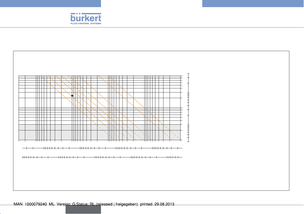
7.3. Graphs
These graphs are used to determine the DN of the pipe and the fitting appropriate to the application, according to the fluid velocity and the flow rate.
fps
/h
3
m
l/min
gpm
1000
200
3000
DN 50 (DN65)*
100
1000
2000
500
DN 40 (DN50)*
DN 32 (DN40)*
DN 25 (DN32)*
20
50
500
100
200
DN 20 (DN25)*
DN 15 (DN15
/ 20)*
5
10
100
200
20
50
Flow rate
50
2
10
DN 08
20
1
5
DN 06
10
0.5
2
0.1
0.2
1
2
5
1
0.5
0.05
0.2
0.02
0.5
0.1
0.01
0.2
0.05
m/s
0.1 0.3 0.5 1 3 5 10
0.3 0.5 1 3 5 10 30
Fluid velocity
/h. If the ideal fluid velocity is 2 to 3 m/s, ,
3
30
English
* For fittings:
• with external thread connections acc. to SMS 1145,
BS 4825 / ASME BPE or DIN 11850 Rg2,série2
• with welding end connections acc. to SMS 3008,
• Clamp connections acc. to SMS 3017/ ISO 2852, BS 4825 /
ASME BPE or DIN 32676
Selection example:
The flow rate in the pipe is 10 m
then use a DN 40 (or DN 50)* pipe according to the graphs.
Page 31

Type 8012
Under normal conditions of use, cable with a cross section
Do not install the cable near high voltage or high frequency
Connect the different earth connections of the installation to
one another in order to remove any differences in potential
Connect the negative power supply terminal to the earth
to eradicate the effects of common mode currents. If this
connection cannot be made directly, a 100 nF/50 V capacitor
can be fitted between the negative power supply terminal
Installation and wiring
7.4. Electrical wiring
danger
Risk of injury due to electrical discharge
• Shut down and isolate the electrical power source before
carrying out work on the system.
• Observe all applicable accident protection and safety regulations for electrical equipment.
note
• Use cables with an operating temperature limit suitable for your
application.
Use a high quality electrical power supply (filtered and
regulated).
•
of 0.75 mm2 should be enough to transmit the signal.
•
cables.
• If this is unavoidable, keep a minimum distance of 30 cm.
Make sure the installation is equipotential (power supply
- 8012):
•
which may arise between two earth connections.
• Correctly connect the cable shielding to the earth.
•
and the earth.
Power supply
12-36VDC
+
-
(*)
8012 with cable gland
8012 with M12 fixed
(**)
Power supply
12-36VDC
+
-
(*)
connector
*) If a direct earth connection is not possible, fit a 100 nF/50 V condenser
between the negative power supply terminal and the earth
**) If the cable used is shielded.
English
31
Page 32

Type 8012
Installation and wiring
7.4.1. Assembling the M12 female
connector
1 2
→ Completely unscrew the
nut [1]
→ Remove the rear section of
the connector [2].
→ Wire the device (see chap.
9.2.3)
Fig. 8 : M12 multi-pin connector (not supplied, ordering code
917116)
7.4.2. Wiring a version with adjustable
M12 fixed connector
Not connected
4
(*)
(12-36 VDC)
5
1
V+
0 VDC
3
2
Pulse output
(NPN by default)
Version with pulse output
Fig. 9 : Pin assignment of the M12 male fixed connector
4-20 mA
4
(*)
(12-36 VDC)
5
1
V+
0 VDC
3
2
Pulse output
(NPN by default)
Version with pulse and current
outputs
Pin of the M12 female cable available as
accessory equipment (order code 438680)
Color of the
wire
1 brown
2 white
3 blue
4 black
5
grey
The M12 fixed connector of the device is adjustable in position:
→ Unscrew the locknut.
→ Turn the fixed connector to the desired position, by 360° max. so
as not to twist the cables inside the enclosure.
→ Tighten the locknut using a spanner, while keeping the fixed
connector in the desired position.
12-36 VDC
+-
34
blue
brown
5
1 2
white
grey
Fig. 10 : NPN wiring (default) of the pulse output of a version with
M12 fixed connector
(*) Functional earth; If a direct earth connection is not possible, fit a 100 nF / 50 V
capacitor between the negative power supply terminal and the earth.
Power supply
(*)
Load
32
English
Page 33

Type 8012
Installation and wiring
12-36 VDC
Power supply
+-
(*)
34
blue
5
1 2
whitebrown
grey
Load
Fig. 11 : PNP wiring of the pulse output of a version with M12 fixed
connector
4-20mA
input at
external
device
+-
12-36 VDC
+-
Power supply
(*)
5
1 2
34
blue
grey
brown
black
Fig. 12 : Wiring the current output in sinking mode (by default) on a
version with M12 fixed connector.
4-20mA
input at
external
device
+-
12-36 VDC
+-
Power supply
(*)
34
black
1 2
blue
grey
5
brown
Fig. 13 : Wiring the current output in sourcing mode on a version
with M12 fixed connector
(*) Functional earth; If a direct earth connection is not possible, fit a 100 nF /
50 V capacitor between the negative power supply terminal and the earth.
7.4.3. Wiring a version with cable gland
Color of the
wire
Signal on a
version with
pulse output
Signal on a
version with
pulse and
current outputs
BN (brown)
V+ (12-36 V DC) 0 V DC
V+ (12-36 V DC) 0 V DC
WH
(white)
GN (green) YE (yellow)
Functional
earth
Functional
earth
Not connected
Current in mA
GY
(grey)
NPN or
PNP
NPN or
PNP
English
33
Page 34

Type 8012
Installation and wiring
12-36 VDC
Power supply
+-
brown
white
green
(*)
YE GY BN WH GN
grey
Load
Fig. 14 : NPN wiring (default) of the pulse output of a version with
cable gland
12-36 VDC
Power supply
+-
brown
white
green
(*)
YE GY BN WH GN
grey
Load
Fig. 15 : PNP wiring of the pulse output of a version with cable
gland
4-20mA input
at external
device
+-
12-36 VDC
+-
Power
supply
(*)
yellow
brown
white
green
YE GY BN WH GN
Fig. 16 : Wiring the current output in sinking mode (by default) on a
version with cable gland
(*) Functional earth; If a direct earth connection is not possible, fit a 100 nF /
50 V capacitor between the negative power supply terminal and the earth.
4-20mA input
at external
device
+-
12-36 VDC
+-
Power
supply
(*)
yellow
brown
white
green
YE GY BN WH GN
Fig. 17 : Wiring the current output in sourcing mode on a version
with cable gland
(*) Functional earth; If a direct earth connection is not possible, fit a 100 nF /
50 V capacitor between the negative power supply terminal and the earth.
34
English
Page 35

Type 8012
Commissioning
8. COMMISSIONING
8.1. Safety instructions
Warning
Danger due to nonconforming commissioning.
Non conforming commissioning may lead to injuries and damage
the device and its surroundings.
• Before commissioning, make sure that the staff in charge have
read and fully understood the contents of the manual.
• In particular, observe the safety recommendations and intended
use.
• The device / the installation must only be commissioned by
suitably trained staff.
note
Risk of damage to the device due to the environment
• Protect this device against electromagnetic interference,
ultraviolet rays and, when installed outdoors, the effects of the
climatic conditions.
9. ADJUSTMENT AND FUNCTIONS
9.1. Safety instructions
Warning
Risk of injury due to non-conforming adjustment.
Non-conforming adjustment could lead to injuries and damage the
device and its surroundings.
• The operators in charge of adjustment must have read and
understood the contents of this manual.
• In particular, observe the safety recommendations and intended
use.
• The device/installation must only be adjusted by suitably trained
staff.
9.2. Pulse output
The pulse output of the device can be parametered with one of the
following functions.
9.2.1. Frequency proportional to a volume
This function is used to generate a pulse each time a predetermined
volume of fluid passed.
English
35
Page 36

Type 8012
Adjustment and functions
9.2.2. Switching function
The pulse output of the 8012 can be parametered to switch a solenoid
valve or activate an alarm.
The following parameters can be preset:
• hysteresis or window operating, inverted or not
• the switching thresholds, low and high
• immediate or delayed switching
Hysteresis operating
The output status changes when a threshold is reached:
• by increasing flow rate, the output status changes when the high
threshold is reached.
• by decreasing flow rate, the output status changes when the low
threshold is reached.
The behaviour of the output depends on the output wiring, NPN or
PNP.
Low
Inverted
High
threshold
Contact
ON
OFF
Low
threshold
Not inverted
High
threshold
Contact
ON
OFF
threshold
Not invertedContact
ON
OFF
Low
threshold
Fig. 19 : PNP pulse output, hysteresis operating, non inverted and
inverted
Window operating
The output status changes when either threshold is reached. The
behaviour of the output depends on the output wiring, NPN or PNP.
Contact
High
threshold
Not inverted
ON
OFF
Fig. 20 : NPN pulse output, window operating, non inverted and
threshold
inverted
Low
High
threshold
ON
OFF
threshold
ON
OFF
Low
Low
threshold
InvertedContact
High
threshold
InvertedContact
High
threshold
Fig. 18 : NPN pulse output, hysteresis operating, non inverted and
inverted
36
English
Page 37

Type 8012
Adjustment and functions
Not invertedContact
ON
OFF
Fig. 21 : PNP pulse output, window operating, non inverted and
threshold
inverted
Low
High
threshold
Contact
ON
OFF
threshold
Low
Inverted
High
threshold
9.2.3. Detection of a change in the fluid
direction (only 8012 with optical
sensor)
On an 8012 with optical sensor, the pulse output can be configured
to indicate a change in the fluid circulation direction. Furthermore the
change of direction can be indicated immediately or after a configurable time delay.
The behaviour of the output depends on the output wiring, NPN or
PNP, and on the operating, inverted or not.
F = Fluid direction same as direction of the arrow on the housing
T = Time delay before switching
T F
ON
OFF
Change
of direction
NPN pulse output, non inverted
Fig. 22 : Detection of the change in fluid circulation direction; NPN
pulse output, not inverted and inverted
ON
OFF
of direction
NPN pulse output, inverted
T F
ON
OFF
Change
of direction
PNP pulse output, non inverted
Fig. 23 : Detection of the change in fluid circulation direction; PNP
pulse output, not inverted and inverted
ON
OFF
of direction
PNP pulse output, inverted
T F
Change
T F
Change
English
37
Page 38

Type 8012
Adjustment and functions
Time delay before switching
Switching occurs if one of the thresholds (low, high) is exceeded for a duration higher than the parametered time delay. The time delay is
applied to both switching thresholds. If the time delay equals 0, switching occurs immediately.
Flow rate
High threshold
Low threshold
2 s 2 s
2 s
Flow rate
High threshold
Low threshold
2 s 2 s
2 s
t
Hysteresis operating
Time delay = 0s
Time delay = 2s
Window operating
Time delay = 0s
Time delay = 2s
NPN output
Inverted
ON
OFF
ON
OFF
ON
OFF
ON
OFF
ON
OFF
ON
OFF
ON
OFF
ON
OFF
Not inverted
Inverted
Not inverted
Not inverted
Inverted
Not inverted
Inverted
NPN pulse output
Hysteresis operating
Time delay = 0s
Time delay = 2s
Window operating
Time delay = 0s
Time delay = 2s
PNP output
Not inverted
Inverted
Not inverted
Inverted
Not inverted
Inverted
Not inverted
Inverted
PNP pulse output
ON
OFF
ON
OFF
ON
OFF
ON
OFF
ON
OFF
ON
OFF
ON
OFF
ON
OFF
Fig. 24 : Examples of behaviour of the 8012 depending on the flow rate in the pipe and the switching operating chosen for the pulse output
38
English
t
Page 39

Type 8012
Adjustment and functions
9.3. Current output
The current output, if one exists, can be parametered with the following
functions:
• an extended output range or the current output range corresponding
to a flow range
• an attenuation of the current variations, different from that of the
basic versions.
9.3.1. Extension of the current range
The current output of the device can be configured to deliver a current
varying from 4 to 21.6 mA, depending on the paddle-wheel rotation
frequency.
mA
22
21,6
20
4
0
Fig. 25 : Curve for the current proportional to the paddle-wheel
rotation frequency
250
275
300
f (Hz)
9.3.2. Conversion of the frequency into a
flow rate
The 8012 can be parametered to convert the paddle-wheel rotation
frequency into a flow rate, in a unit specific to the application.
In this case, the 8012 is parametered with the K factor of the device
and the desired flow rate unit.
The following flow units are available:
l/s, l/min., l/h, m
USGa/min., USGa/h.
The current output then delivers a current of 4 to 20 mA or 4 to 21.6 mA
proportional to a flow rate range:
mA
21,6
20
4
0
Fig. 26 : Curve for the current proportional to the flow rate
10
3
/min., m3/h, Ga/s, Ga/min., Ga/h, USGa/s,
800
880
Flow rate (l/min., for
example)
English
39
Page 40

Type 8012
t (s)
t (s)
Maintenance and troubleshooting
9.3.3. Current attenuation variations
When the flow varies quickly, the current output signal from your device
can be stabilised.
The device can be configured with one of the 10 filter levels available,
varying from no filter to maximum filter.
Signal with minimum filter
t (s)
Signal without filter
Signal with maximum filter
Fig. 27 : Different filter levels for current fluctuations
10. MAINTENANCE AND
TROUBLESHOOTING
10.1. Safety instructions
danger
Risk of injury due to high pressure in the installation.
• Stop the circulation of fluid, cut off the pressure and drain the
pipe before loosening the process connections.
Risk of injury due to electrical voltage.
• Shut down and isolate the electrical power source before carrying out work on the system.
• Observe all applicable accident protection and safety regulations for electrical equipment.
Risk of injury due to high fluid temperatures.
• Use safety gloves to handle the device.
• Stop the circulation of fluid and drain the pipe before loosening
the process connections.
Risk of injury due to the nature of the fluid.
• Respect the prevailing regulations on accident prevention and
safety relating to the use of aggressive fluids.
40
English
Page 41

Type 8012
Maintenance and troubleshooting
Warning
Risk of injury due to non-conforming maintenance.
• Maintenance must only be carried out by qualified and skilled
staff with the appropriate tools.
• Ensure that the restart of the installation is controlled after any
interventions.
10.2. Cleaning
Depending on the nature of the fluid, regularly check for clogging of
the paddle-wheel.
note
The device may be damaged by the cleaning liquid.
• Clean the device with a cloth slightly dampened with water or a
cleaning liquid compatible with the materials the device is made
of.
10.3. Replacing the seal
O-ring for plastic fitting
Fig. 28 : Exploded view of the 8012
O-ring for metal fitting
→ Unscrew the 4 screws in the electronic module and remove it
from the fitting.
→ Remove the used seal.
→ Clean the surfaces on which the seal is placed.
→ Insert the new seal (see Fig. 28).
→ Position the electronic module on the fitting so that the arrow
points in the fluid direction on versions with optical sensor.
→ Insert the 4 screws into the electronic module (use the long
screws for a plastic S012, DN6 or DN8 fitting).
→ Tighten the 4 screws in an alternating pattern, to a torque of
1.5 Nm.
English
41
Page 42

Type 8012
Maintenance and troubleshooting
10.4. If you encounter problems
danger
Risk of injury due to high pressure in the installation.
• Stop the circulation of fluid, cut off the pressure and drain the
pipe before loosening the process connections.
Risk of injury due to electrical voltage.
• Shut down and isolate the electrical power source before carrying out work on the system.
• Observe all applicable accident protection and safety regulations for electrical equipment.
Risk of injury due to high fluid temperatures.
• Use safety gloves to handle the device.
• Stop the circulation of fluid and drain the pipe before loosening
the process connections.
Risk of injury due to the nature of the fluid.
• Respect the prevailing regulations on accident prevention and
safety relating to the use of aggressive fluids.
10.4.1. Problems signalled by the LEDs
Status
red LED
Flashes
3 times
every
second
On Off 22 mA Memory
Off Flashes
Status
green
LED
Off 22 mA Full scale
twice
every
second
Status
current
output
22 mA The device
Possible
cause
exceeded (flow
rate in the pipe
is too high)
problem
with optical
detection is
mounted in the
wrong direction
Recommended
action
Check the process
parameters
Switch the power
supply off then on.
If the error persists, contact your
Bürkert retailer.
Mount the device,
ensuring that the
arrow on the side
of the housing indicates the direction
of the fluid.
42
English
Page 43

Type 8012
Maintenance and troubleshooting
10.4.2. Problems not signalled by the LEDs
Problem Recommended action see chap.
The device does not
function
The pulse output
does not work
The current output
does not work
The flow rate measurement is incorrect
• Check the wiring
• Check that the device is
energized
Check whether the wiring is
suitable for the output type,
NPN or PNP
Check whether the wiring is
suitable for the output type,
source or sink
Recalculate and change the
setting of the K factor
7.4
7.4
7.4
6.3.5
11. SPARE PARTS AND ACCESSORIES
attention
Risk of injury and/or damage caused by the use of unsuitable
parts.
Incorrect accessories and unsuitable spare parts may cause
injuries and damage the device and the surrounding area.
• Use only original accessories and original spare parts from
Bürkert.
Spare part Order code
Seal for metal fitting (Fig. 29)
FKM (DN6 to DN65) 426340
EPDM (DN6 to DN65) 426341
Set of 2 O-rings for the end pieces (true
union connections only) + 1 flat seal and
1 O-ring for the SE12 electronic module
connection (Fig. 30)
FKM - DN8 448679
FKM - DN15 431555
FKM - DN20 431556
FKM - DN25 431557
FKM - DN32 431558
FKM - DN40 431559
FKM - DN50 431560
English
43
Page 44

Spare part Order code
EPDM - DN8 448680
EPDM - DN15 431561
EPDM - DN20 431562
EPDM - DN25 431563
EPDM - DN32 431564
EPDM - DN40 431565
EPDM - DN50 431566
Set of screws: 4 short screws (M4x35 - A4) + 4
long screws (M4x60 - A4)
Accessory Order code
5-pin M12 female connector, moulded on
shielded cable (2 m)
5-pin M12 female connector, to be wired 917116
Set including:
• 1 CD with TACT (TrAnsmitter Configuration
Tool) configuration software
• 1 TACT interface board
• 2 connection cables
Set of connection cables for the TACT interface 556160
555775
438680
556500
Type 8012
Maintenance and troubleshooting
Fig. 29 : Seal for metal fitting
Fig. 30 : Seals for plastic fitting
44
English
Page 45

Type 8012
Packaging, transport, storage
12. PACKAGING, TRANSPORT,
STORAGE
attention
Damage due to transport
Transport may damage an insufficiently protected part.
• Transport the device in shock-resistant packaging and away
from humidity and dirt.
• Do not expose the device to temperatures that may exceed the
admissible storage temperature range.
• Protect the electrical interfaces using protective plugs.
Poor storage can damage the device.
• Store the device in a dry place away from dust.
• Storage temperature -15 to +60°C.
Damage to the environment caused by products contaminated by fluids.
• Dispose of the device and its packaging in an environmentallyfriendly way.
• Keep to the existing provisions on the subject of waste disposal
and environmental protection.
English
45
Page 46

Type 8012
46
English
Page 47

Typ 8012
Inhaltsverzeichnis
1. DIE BEDIENUNGSANLEITUNG ...............................................................5
1.1. Darstellungsmittel ..............................................................................5
1.2. Begriffsdefinition "Gerät" ................................................................5
2. BESTIMMUNGSGEMÄSSE VERWENDUNG ......................................6
2.1. Beschränkungen .................................................................................6
3. GRUNDLEGENDE SICHERHEITSHINWEISE ....................................6
4. ALLGEMEINE HINWEISE .............................................................................8
4.1. Herstelleradresse und internationale Kontaktadressen 8
4.2. Gewährleistung ....................................................................................8
4.3. Informationen im Internet ...............................................................8
5. BESCHREIBUNG .............................................................................................8
5.1. Vorgesehener Einsatzbereich ......................................................8
5.2. Allgemeine Beschreibung ..............................................................8
5.2.1. Aufbau ...................................................................................... 8
5.2.2. Version mit Pulsausgang ..................................................... 9
5.2.3. Version mit Pulsausgang und Stromausgang ...............10
5.3. Beschreibung des Typenschilds des 8012 ........................ 11
5.4. Beschreibung des Typenschilds des SE12 ...........................11
5.5. Bestellnummern der Basisversionen des Moduls
SE12 ........................................................................................................ 12
6. TECHNISCHE DATEN ................................................................................ 14
6.1. Betriebsbedingungen .................................................................... 14
6.2. Einhaltung von Normen und Richtlinien ..............................14
6.3. Allgemeine Technische Daten ..................................................14
6.3.1. Mechanische Daten ............................................................14
6.3.2. Allgemeine Daten ................................................................21
6.3.3. Elektrische Daten ................................................................23
6.3.4. Elektrische Anschlüsse ......................................................23
6.3.5. K-Faktoren .............................................................................23
7. INSTALLATION UND VERKABELUNG ...............................................25
7.1. Sicherheitshinweise ....................................................................... 25
7.2. Fluidischer Anschluss ................................................................... 26
7.2.1. Empfehlungen für die Montage des 8012 in die
Rohrleitung............................................................................26
7.2.2. Installation eines Gerätes mit Schweißstutzen-
Anschlüssen .........................................................................28
7.2.3. Installation eines Gerätes mit Clamp-Anschlüssen.....29
7.2.4. Installation eines Gerätes mit Flansch-Anschlüssen ..29
7.3. Geeignete Nennweiten-Auswahl .............................................30
7.4. Verkabelung ........................................................................................ 31
7.4.1. Bauen Sie die M12-Buchse zusammen ........................32
deutsch
3
Page 48

Typ 8012
7.4.2. Verkabelung einer Version mit ausrichtbarem
M12-Gerätestecker ............................................................32
7.4.3. Verkabelung der Version mit Kabelverschraubung ......33
8. INBETRIEBNAHME ...................................................................................... 35
8.1. Sicherheitshinweise ....................................................................... 35
9. BEDIENUNG UND FUNKTION .............................................................. 35
9.1. Sicherheitshinweise ....................................................................... 35
9.2. Pulsausgang .......................................................................................35
9.2.1. Zu einem Volumen proportionale Frequenz ..................35
9.2.2. Schaltfunktion ......................................................................36
9.2.3. Erkennung der Fließrichtungsumkehr (nur 8012
mit optischem Sensor) .......................................................37
9.3. Stromausgang ................................................................................... 39
9.3.1. Erweiterung des Strombereichs ......................................39
9.3.2. Umwandlung der Frequenz in einen Durchfluss ..........39
9.3.3. Dämpfung der Stromschwankungen ..............................40
10. WARTUNG, FEHLERBEHEBUNG....................................................... 40
10.1. Sicherheitshinweise ....................................................................... 40
10.2. Wartung und Reinigung ................................................................ 41
10.3. Wechseln der Dichtung .................................................................41
10.4. Problemlösung .................................................................................. 42
10.4.1. Durch die LEDs angezeigte Probleme ...........................42
10.4.2. Nicht durch die LEDs angezeigte Probleme .................43
11. ERSATZTEILE UND ZUBEHÖR...........................................................43
12. VERPACKUNG, TRANSPORT, LAGERUNG ..................................45
4
deutsch
Page 49

Typ 8012
Warnt vor Sachschäden!
Die Bedienungsanleitung
1. DIE BEDIENUNGSANLEITUNG
Die Bedienungsanleitung beschreibt den gesamten Lebenszyklus
des Gerätes. Bewahren Sie diese Anleitung so auf, dass sie für jeden
Benutzer zugänglich ist und jedem neuen Eigentümer des Gerätes
wieder zur Verfügung steht.
Diese Bedienungsanleitung enthält wichtige Informationen zur
Sicherheit!
Das Nichtbeachten dieser Hinweise kann zu gefährlichen Situationen führen.
• Die Bedienungsanleitung muss gelesen und verstanden werden.
1.1. Darstellungsmittel
Gefahr!
Warnt vor einer unmittelbaren Gefahr!
• Bei Nichteinhaltung sind Tod oder schwere Verletzungen die
Folge.
WarnunG!
Warnt vor einer möglicherweise gefährlichen Situation!
• Bei Nichteinhaltung drohen schwere Verletzungen oder Tod.
VOrSIChT!
Warnt vor einer möglichen Gefährdung!
• Nichtbeachtung kann mittelschwere oder leichte Verletzungen
zur Folge haben.
hInWeIS!
• Bei Nichtbeachtung kann das Gerät oder die Anlage beschädigt
werden.
bezeichnet wichtige Zusatzinformationen, Tipps und
Empfehlungen.
verweist auf Informationen in dieser Bedienungsanleitung
oder in anderen Dokumentationen.
→ markiert einen Arbeitsschritt, den Sie ausführen müssen.
1.2. Begriffsdefinition "Gerät"
→ Der in dieser Anleitung verwendete Begriff "Gerät" steht immer
für das Durchfluss-Messgerät Typ 8012.
deutsch
5
Page 50

Typ 8012
Bestimmungsgemässe Verwendung
2. BESTIMMUNGSGEMÄSSE
VERWENDUNG
Bei nicht bestimmungsgemäßem Einsatz dieses DurchflussMessgerätes können Gefahren für Personen, Anlagen in der
Umgebung und die Umwelt entstehen.
• Das Durchfluss-Messgerät 8012 ist ausschließlich für die
Durchflussmessung in Flüssigkeiten bestimmt.
• Schützen Sie das Gerät vor elektromagnetischen Störungen, U.V.-Bestrahlung und bei Außenanwendung vor
Witterungseinflüssen.
• Für den Einsatz sind die in den Vertragsdokumenten und der
Bedienungsanleitung spezifizierten zulässigen Daten, Betriebsund Einsatzbedingungen zu beachten.
• Zum sicheren und problemlosen Einsatz des Gerätes müssen
Transport, Lagerung und Installation ordnungsgemäß erfolgen,
außerdem müssen Betrieb und Wartung sorgfältig durchgeführt
werden.
• Achten Sie immer darauf, dieses Gerät auf ordnungsgemäße
Weise zu verwenden.
2.1. Beschränkungen
Beachten Sie bei der Ausfuhr des Gerätes gegebenenfalls bestehende
Beschränkungen.
3. GRUNDLEGENDE SICHERHEITSHINWEISE
Diese Sicherheitshinweise berücksichtigen keine
• Zufälligkeiten und Ereignisse, die bei Montage, Betrieb und Wartung
der Geräte auftreten können.
• Ortsbezogenen Sicherheitsbestimmungen, für deren Einhaltung,
auch in Bezug auf das Installations- und Wartungspersonal, der
Betreiber verantwortlich ist.
Gefahr durch hohen Druck in der Anlage!
Gefahr durch elektrische Spannung!
Gefahr durch hohe Flüssigkeitstemperaturen!
Gefahr aufgrund der Art der Flüssigkeit!
Allgemeine Gefahrensituationen.
Zum Schutz vor Verletzungen ist zu beachten
• Dass die Anlage nicht unbeabsichtigt betätigt werden kann.
• Installations- und Instandhaltungsarbeiten dürfen nur von autorisiertem Fachpersonal mit geeignetem Werkzeug ausgeführt
werden.
• Nach einer Unterbrechung der elektrischen Versorgung ist ein
definierter oder kontrollierter Wiederanlauf des Prozesses zu
gewährleisten.
6
deutsch
Page 51

Typ 8012
Das Gerät kann durch das Medium beschädigt werden.
Elektrostatisch gefährdete Bauelemente / Baugruppen!
Bestimmungsgemässe Verwendung
hInWeIS!
Allgemeine Gefahrensituationen.
Zum Schutz vor Verletzungen ist zu beachten
• Betreiben Sie das Gerät nur in einwandfreiem Zustand und
unter Beachtung der Bedienungsanleitung.
• Bei der Einsatzplanung und dem Betrieb des Fittings die allgemeinen Regeln der Technik einhalten.
• Dieses Gerät nicht in einem explosionsgefährdeten Bereich
verwenden.
• Dieses Gerät nicht für die Durchflussmessung von Gas einsetzen.
• Keine Flüssigkeit verwenden, die sich nicht mit den Werkstoffen
verträgt, aus denen das Gerät besteht.
• Dieses Gerät nicht in einer Umgebung verwenden, die mit den
Materialien, aus denen es besteht, inkompatibel ist.
• Belasten Sie das Gerät nicht mechanisch (z. B. durch Ablage von
Gegenständen oder als Trittstufe).
• Nehmen Sie keine äußerlichen Veränderungen an den Gehäusen
vor. Lackieren Sie keinen Teil des Gerätes.
hInWeIS!
• Kontrollieren Sie systematisch die chemische Verträglichkeit der
Werkstoffe, aus denen das Gerät besteht, und der Flüssigkeiten,
die mit diesem in Berührung kommen können (zum Beispiel: Alkohole, starke oder konzentrierte Säuren, Aldehyde, Basen, Ester,
aliphatische Verbindungen, Ketone, aromatische oder halogenierte Kohlenwasserstoffe, Oxidations- und chlorhaltige Mittel).
• Das Gerät enthält elektronische Bauelemente, die gegen elektrostatische Entladung (ESD) empfindlich reagieren. Berührung
mit elektrostatisch aufgeladenen Personen oder Gegenständen
gefährdet diese Bauelemente. Im schlimmsten Fall werden sie
sofort zerstört oder fallen nach der Inbetriebnahme aus.
• Beachten Sie die Anforderungen nach EN 61340 -5-1 und 5-2,
um die Möglichkeit eines Schadens durch schlagartige elektrostatische Entladung zu minimieren bzw. zu vermeiden!
• Achten Sie ebenso darauf, dass Sie elektronische Bauelemente
nicht bei anliegender Versorgungsspannung berühren!
deutsch
7
Page 52

Typ 8012
Allgemeine Hinweise
4. ALLGEMEINE HINWEISE
4.1. Herstelleradresse und internationale Kontaktadressen
Sie können mit dem Hersteller des Gerätes unter folgender Adresse
Kontakt aufnehmen:
Bürkert SAS
Rue du Giessen
BP 21
F-67220 TRIEMBACH-AU-VAL
oder wenden Sie sich an Ihren lokal zuständigen Vertriebsmitarbeiter
von Bürkert.
Die internationalen Kontaktadressen finden Sie auf den letzten
Seiten dieser Bedienungsanleitung.
Außerdem im Internet unter: www.burkert.com
4.2. Gewährleistung
Voraussetzung für die Gewährleistung ist der bestimmungsgemäße
Gebrauch des Messgerätes 8012 unter Beachtung der im vorliegenden Handbuch spezifizierten Einsatzbedingungen.
4.3. Informationen im Internet
Bedienungsanleitungen und Datenblätter zum Typ 8012 finden Sie
im Internet unter: www.buerkert.de
5. BESCHREIBUNG
5.1. Vorgesehener Einsatzbereich
Das Durchfluss-Messgerät 8012 mit Magnetsensor ist für die Durchflussmessung neutraler oder leicht aggressiver Flüssigkeiten ohne
Feststoffpartikel bestimmt.
Das Durchfluss-Messgerät 8012 mit optischem Sensor ist ausschließlich zur Durchflussmessung von Flüssigkeiten bestimmt, die
durchlässig für Infrarotlicht sind.
5.2. Allgemeine Beschreibung
5.2.1. Aufbau
Das Gerät 8012 besteht aus einem Elektronikmodul SE12 mit integriertem Flügelrad und einem Fitting S012 zur Montage des Gerätes
an jeder Art von Rohrleitung mit DN6 bis DN65.
Das Gerät detektiert die Rotation des Flügelrads und erzeugt ein
Signal, dessen Frequenz f proportional zur Rotationsfrequenz des
Flügelrads ist.
Das Elektronikmodul ist mit 2 LEDs ausgestattet, die durch die Seite
des Gehäuses hindurch erkennbar sind:
• Eine grüne LED leuchtet, wenn das Gerät mit Strom versorgt ist
(Flügelrad steht still) und blinkt dann proportional zur Rotationsfrequenz des Flügelrads.
8
deutsch
Page 53

Typ 8012
Allgemeine Hinweise
• Eine rote LED signalisiert Fehlfunktionen des Gerätes (siehe Kap.
10.4.1).
Der elektrische Anschluss erfolgt je nach Version über eine Kabelverschraubung mit angeschlossenem Kabel, 1 m lang, oder über einen
ausrichtbaren M12-Gerätestecker.
Das Gerät ist je nach Version ausgestattet mit:
• einem Pulsausgang
• oder einem Pulsausgang und einem Stromausgang 4-20 mA.
SE12
Flügelrad
S012
Lokalisierung der LEDs (je
nach Version)
5.2.2. Version mit Pulsausgang
Bei den 16 Basisversionen des Moduls SE12 (siehe Kap. 5.5) erzeugt
der NPN-Pulsausgang ein Signal, dessen Frequenz f proportional zur
Rotationsfrequenz des Flügelrads ist.
Um den Durchfluss Q zu ermitteln, muss diese Frequenz durch einen
Proportionalitätsfaktor K gemäß der folgenden Formel geteilt werden:
Q = f/K
Tabelle 1: Eigenschaften des Pulsausgangs
Eigenschaften des
Mögliche Konfigurationen (auf Anfrage)
Pulsausgangs
Anschluss des
Transistors
Verhalten des
Ausgangs
• NPN
• oder PNP
• Zur Rotation des Flügelrads proportionale
Frequenz (siehe oben)
• oder: zu einem
Volumen proportionale
Frequenz (siehe Kap.
9.2.1)
• oder: Schaltmodus
(siehe Kap. 9.2.2)
• oder: Modus der
sofortigen oder verzögerten Erkennung der
Flussrichtungsumkehr
(nur bei den Versionen
mit optischem Sensor)
(siehe Kap. 9.2.3)
Pulsausgang der
Basisversionen
NPN
Zur Rotation des
Flügelrads proportionale Frequenz
deutsch
9
Page 54

Typ 8012
mA
0
20
4
Q
Q =
(I - 4)
125
8K
Allgemeine Hinweise
5.2.3. Version mit Pulsausgang und
Stromausgang
Pulsausgang
Die Eigenschaften des Pulsausgangs sind mit den Eigenschaften einer
Version identisch, die nur einen Pulsausgang besitzt. Siehe Kap. 5.2.2.
Stromausgang
Der Stromausgang der Basisversionen wird als Senke angeschlossen
und liefert einen Strom I, der der Rotationsfrequenz f des Flügelsrads
entspricht:
I = 8f/125 + 4
Mit f=KQ ist der Durchfluss Q proportional zu diesem Strom:
Q: Durchfluss [Liter/s]
K: K-Faktor [Pulse/Liter]
I: Strom [mA]
Durchfluss
Dämpfung der Stromschwankungen
Wenn sich der Durchfluss schnell verändert, kann das Signal des
Stromausgangs des Gerätes stabilisiert werden. Bei den Basisversionen werden die Stromschwankungen wenig gedämpft.
Auslösung eines Alarmstroms (nur Versionen mit optischem
Sensor)
Bei den Basisversionen wird ein "Alarmstrom" von 22 mA erzeugt,
wenn die Fließrichtung umgekehrt zur Richtung des Pfeils an der
Gehäuseseite ist.
10
deutsch
Tabelle 2: Eigenschaften des Stromausgangs
Eigenschaft Mögliche Konfigurationen
(auf Anfrage)
Verkabelung • als Quelle
• oder als Senke
Bereich des
Stromausgangs und
entsprechender
Messbereich
• 4-20 mA, entsprechend dem
Rotationsfrequenzbereich
0-250 Hz des Flügelrads (siehe
oben)
• oder: 4-20 mA, entsprechend
einem Durchflussbereich in
der anwendungsspezifischen
Einheit (siehe Kap. 9.3.1)
• oder: 4-21,6 mA, entsprechend
dem Rotationsfrequenzbereich
0-275 Hz des Flügelrads (siehe
Kap. 9.3.1)
• oder: 4-21,6 mA, entsprechend
einem Durchflussbereich in
der anwendungsspezifischen
Einheit (siehe Kap. 9.3.2)
Dämpfung der
Strom-Schwankungen
10 verfügbare Dämpfungsstufen: von "keine Dämpfung" bis
maximale Dämpfung (siehe Kap.
9.3.3)
Konfiguration einer
Basisversion
als Senke
4-20 mA,
entsprechend
dem RotationsFrequenzBereich
0-250 Hz des
Flügelrads
Geringe
Dämpfung der
Stroms-chwankungen
Page 55

Typ 8012
Allgemeine Hinweise
5.3. Beschreibung des Typenschilds des 8012
1
FLOW:8012 HALL
NPN/PNP : 0,7A - 36 VDC
12-36 VDC 4-20 mA
MS FKM 0,3-10 M/S
S-N:1092
Made in France
00557060 W47LE
1. Messgröße und Typ des Gerätes
2. Sensor-Typ
3. Daten des Pulsausgangs
4. Typ des Stromausgangs
5. Durchflussbereich
6. Konformitäts-Logo
7. Herstellungscode
8. Werkstoffe des Fittings und der Dichtung, die in Kontakt mit der
Flüssigkeit sind
9. Seriennummer
10. Bestellnummer
11. Betriebsspannung
2
3
4
5
8 11 10
6 7 9
5.4. Beschreibung des Typenschilds des SE12
1
FLOW:SE12 HALL
NPN/PNP : 0,7A - 36 VDC
12-36 VDC 4-20 mA
0,3-10 M/S
S-N:1092
Made in France
00557060 W47LE
1. Messgröße und Typ des Gerätes
2. Sensor-Typ
3. Daten des Pulsausgangs
4. Typ des Stromausgangs
5. Durchflussbereich
6. Konformitäts-Logo
7. Herstellungscode
8. Seriennummer
9. Bestellnummer
10. Betriebsspannung
2
3
4
5
8 10
6 7 9
deutsch
11
Page 56

Typ 8012
Allgemeine Hinweise
5.5. Bestellnummern der Basisversionen des Moduls SE12
Das Fitting S012 ist als Einzelteil nicht verfügbar.
Jeweils zwei Versionen der Fittings S012 mit DN15 und DN20 mit verschiedenen K-Faktoren sind vorhanden.
Nur die Version 2 mit der Markierung "v2" ist ab März 2012 verfügbar. Die Markierung "v2" befindet sich
V2
• auf der Unterseite eines DN15 oder DN20 aus Kunststoff:
V2
• auf der Seite eines DN15 oder DN20 aus Metall:
Betriebsspannung Messprinzip Fitting Elektrischer Anschluss Ausgänge Bestellnummer
DN6, DN8, DN15
v2 und DN20 v2
12-36 V DC Hall
DN15 bis DN65
(außer DN15 v2
und DN20 v2)
12
5-poliger M12-Gerätestecker
Kabelveschraubung, inkl.
angeschlossener Kabel 1 m
5-poliger M12-Gerätestecker
Kabelveschraubung, inkl.
angeschlossener Kabel 1 m
deutsch
Puls, NPN 557054
Puls, NPN + 4-20 mA 557058
Puls, NPN 557056
Puls, NPN + 4-20 mA 557060
Puls, NPN 557053
Puls, NPN + 4-20 mA 557057
Puls, NPN 557055
Puls, NPN + 4-20 mA 557059
Page 57

Typ 8012
Allgemeine Hinweise
12-36 V DC Optisch
DN6, DN8, DN15
v2 und DN20 v2
DN15 bis DN65
(außer DN15 v2
und DN20 v2)
5-poliger M12-Gerätestecker
Kabelveschraubung, inkl.
angeschlossener Kabel 1 m
5-poliger M12-Gerätestecker
Kabelveschraubung inkl.
angeschlossener Kabel, 1 m
Puls, NPN 557062
Puls, NPN + 4-20 mA 557066
Puls, NPN 557064
Puls, NPN + 4-20 mA 557068
Puls, NPN 557061
Puls, NPN + 4-20 mA 557065
Puls, NPN 557063
Puls, NPN + 4-20 mA 557067
deutsch
13
Page 58

Typ 8012
Technische Daten
6. TECHNISCHE DATEN
6.1. Betriebsbedingungen
Temperaturbereich -15 bis +60 °C
Luftfeuchtigkeit < 80 %, nicht kondensierend
Schutzart • IP67 (Version mit M12-Geräte-
stecker), Buchse verkabelt, eingesteckt und festgezogen
• IP65 (Version mit
Kabelverschraubung)
6.2. Einhaltung von Normen und Richtlinien
Durch folgende Normen wird die Konformität mit den EG-Richtlinien
erfüllt:
• EMV: EN 61000-6-2, EN 61000-6-3
• Sicherheit: EN 61 010-1
• Vibration: EN 60068-2-6
• Schock: EN 60068-2-27
• Druck (Fitting S012 von DN06 bis DN65 aus PP, PVC, PVDF,
Messing oder Edelstahl): Das Gerät kann nur unter folgenden
Bedingungen eingesetzt werden (abhängig vom maximalen Druck,
vom DN der Rohrleitung und von der Flüssigkeit)
Art der Flüssigkeit Voraussetzungen
Flüssigkeitsgruppe 1
Kap. 1.3.a
Flüssigkeitsgruppe 2
Kap. 1.3.a
Flüssigkeitsgruppe 1
Kap. 1.3.b
Flüssigkeitsgruppe 2
Kap. 1.3.b
nur DN ≤ 25
DN ≤ 32
oder DN > 32 und PNxDN ≤ 1000
PNxDN ≤ 2000
DN ≤ 200
6.3. Allgemeine Technische Daten
6.3.1. Mechanische Daten
Komponente Werkstoff
Elektronikgehäuse SE12 PPS
Kabelverschraubung,
M12-Gerätestecker
Kabel, 1 m PVC, t
Dichtung in Kontakt mit der
Flüssigkeit
Dichtung in Kontakt mit der
umgebenden Luft
Armatur des Flügelrads PVDF
Flügelrad PVDF
PA
= 80 °C
max
FKM (EDPM auf Anfrage)
EDPM
14
deutsch
Page 59

Typ 8012
Technische Daten
Komponente Werkstoff
Flügelrad-Achse und -Lager Keramik
Gehäuse des Fittings S012
Edelstahl (316L/DIN1.4404),
Messing, PVC, PP, PVDF
Schrauben Edelstahl A4
Kabel
L = 1 m
68
69
46
40
50
35
Bild 1: Abmessungen des Moduls SE12
Tabelle 3: Abmessungen des 8012 mit Innengewinde-
Anschlüssen nach G, Rc oder NPT, aus Edelstahl oder
Messing
DN [mm] P [mm] A [mm] D [Zoll] L [mm]
15 57.5 84.0 G 1/2
NPT 1/2
Rc 1/2
20 55.0 94.0 G 3/4
NPT 3/4
Rc 3/4
16.0
17.0
15.0
17.0
18.3
16.3
25 55.2 104.0 G 1
NPT 1
Rc 1
32 58.8 119.0 G 1 3/4
NPT 1 3/4
Rc 1 3/4
40 62.6 129.0 G 1 1/2
NPT 1 1/2
Rc 1 1/2
50 68.7 148.5 G 2
NPT 2
Rc 2
23.5
18.0
18.0
23.5
21.0
21.0
23.5
20.0
19.0
27.5
24.0
24.0
P
D
L
A
Tabelle 4: Abmessungen des 8012 mit Außengewinde-
Anschlüssen nach SMS 1145 aus Edelstahl
DN [mm] P [mm] A [mm] D [Zoll]
25 55.0 130 Rd40 x 1/6"
40 58.8 164 Rd60 x 1/6"
50 62.6 173 Rd70 x 1/6"
deutsch
15
Page 60

Typ 8012
D
Technische Daten
P
A
Tabelle 5: Abmessungen des 8012 mit Außengewinde-
Anschlüssen nach G, Rc oder NPT, aus Edelstahl,
Messing, PVC oder PVDF
DN
[mm]P[mm]A[mm]D[Zoll] [mm]
6 52.5 90.0 G 1/4 oder G 1/2 - 14.0
8 52.5 90.0 G 1/2 oder NPT 1/2
oder Rc 1/2
15 57.5 84.0 G 3/4 - 11.5
20 55.0 94.0 G 1 - 13.5
25 55.2 104.0 G 1 1/4 - 14.0
32 58.8 119.0 G 1 1/2 - 18.0
40 62.6 129.0 - M55 x 2 19.0
50 68.7 148.5 - M64 x 2 20.0
M16 x 1.5 14.0
L
[mm]
P
D
L
A
Tabelle 6: Abmessungen des 8012 mit Schweißstutzen-
Anschlüssen nach EN ISO 1127 / ISO
4200, SMS 3008, BS 4825/ASME BPE und
DIN 11850 Reihe 2 aus Edelstahl
DN
[mm]P[mm]A[mm]
8 -
-
-
52.5
15 57.5
-
-
57.5
-
-
-
90.0
84.0
-
-
84.0
Norm
EN ISO 1127 / ISO
4200
SMS 3008
ASME BPE
DIN 11850 Reihe 2
EN ISO 1127 / ISO
4200
SMS 3008
ASME BPE
DIN 11850 Reihe 2
D
[mm]s[mm]
-
-
-
13.00
21.30
-
-
19.00
-
-
-
1.50
1.60
-
-
1.50
16
deutsch
Page 61

Typ 8012
Technische Daten
20 55.0
-
57.5
57.5
25 55.2
55.0
55.0
55.0
32 58.8
-
55.2
55.2
40 62.6
58.8
58.8
58.8
50 68.7
62.6
62.6
62.6
94.0
-
84.0
84.0
104.0
94.0
94.0
94.0
119.0
-
104.0
104.0
129.0
119.0
119.0
119.0
148.5
128.0
128.0
128.0
EN ISO 1127 / ISO
4200
SMS 3008
ASME BPE
DIN 11850 Reihe 2
EN ISO 1127 / ISO
4200
SMS 3008
ASME BPE
DIN 11850 Reihe 2
EN ISO 1127 / ISO
4200
SMS 3008
ASME BPE
DIN 11850 Reihe 2
EN ISO 1127 / ISO
4200
SMS 3008
ASME BPE
DIN 11850 Reihe 2
EN ISO 1127 / ISO
4200
SMS 3008
ASME BPE
DIN 11850 Reihe 2
26.90
-
19.05
23.00
33.70
25.00
25.40
29.00
42.40
-
32.00
35.00
48.30
38.00
38.10
41.00
60.30
51.00
50.80
53.00
1.60
-
1.65
1.50
2.00
1.20
1.65
1.50
2.00
-
1.65
1.50
2.00
1.20
1.65
1.50
2.60
1.20
1.65
1.50
65 -
68.7
68.7
-
-
147.0
147.0
-
s
EN ISO 1127 / ISO
4200
SMS 3008
ASME BPE
DIN 11850 Reihe 2
-
63.50
63.50
-
P
-
1.60
1.65
-
D
A
Tabelle 7: Abmessungen des 8012 mit Clamp-Anschlüssen nach
ISO (für Rohrleitungen nach EN ISO 1127 / ISO 4200),
SMS 3017/ISO 2852 1), BS 4825 / ASME BPE 1) und
1)
Verfügbar mit Innenrauigkeit Ra = 0,8 μm
DN
[mm]P[mm]A[mm]
8 -
DIN 32676 aus Edelstahl
Norm
-
ISO (Rohr EN ISO
1127 / ISO 4200)
-
-
SMS 3017/ ISO 2852
-
-
ASME BPE
52.5
125
DIN 32676
D2
[mm]D1[mm]D[mm]
-
-
-
-
-
-
-
-
-
10.00
27.5
34.0
deutsch
17
Page 62

Typ 8012
Technische Daten
15 57.5
-
-
52.5
20 55.0
-
57.5
57.5
25 55.2
55.0
55.0
55.0
32 58.8
-
-
-
130.0
-
-
119.0
150.0
-
119.0
119.0
160.0
129.0
129.0
136.0
180.0
-
-
-
ISO (Rohr EN ISO
1127 / ISO 4200)
SMS 3017/ ISO 2852
ASME BPE
DIN 32676
ISO (Rohr EN ISO
1127 / ISO 4200)
SMS 3017/ ISO 2852
ASME BPE
DIN 32676
ISO (Rohr EN ISO
1127 / ISO 4200)
SMS 3017/ ISO 2852
ASME BPE
DIN 32676
ISO (Rohr EN ISO
1127 / ISO 4200)
SMS 3017/ ISO 2852
ASME BPE
DIN 32676
18.10
-
-
16.00
23.70
-
15.75
20.00
29.70
22.60
22.10
26.00
38.4
-
-
-
27.5
-
-
27.5
43.5
-
19.6
27.5
43.5
43.5
43.5
43.5
43.5
-
-
-
34.0
-
-
34.0
50.5
-
25.0
34.0
50.5
50.5
50.5
50.5
50.5
-
-
-
40 62.6
58.8
58.8
58.8
50 68.7
62.6
62.6
62.6
65 -
68.7
68.7
-
P
200.0
161.0
161.0
161.0
230.0
192.0
192.0
170.0
-
216.0
216.0
-
ISO (Rohr EN ISO
1127 / ISO 4200)
SMS 3017/ ISO 2852
ASME BPE
DIN 32676
ISO (Rohr EN ISO
1127 / ISO 4200)
SMS 3017/ ISO 2852
ASME BPE
DIN 32676
ISO (Rohr EN ISO
1127 / ISO 4200)
SMS 3017/ ISO 2852
ASME BPE
DIN 32676
44.3
35.6
34.8
38.0
55.1
48.6
47.5
50.0
-
60.3
60.2
-
56.5
43.5
43.5
43.5
70.5
56.5
56.5
56.5
-
70.5
70.5
-
D2
D1
64.0
50.5
50.5
50.5
77.5
64.0
64.0
64.0
-
77.5
77.5
-
D
18
A
deutsch
Page 63

Typ 8012
Technische Daten
Tabelle 8: Abmessungen des 8012 mit Flansch-Anschlüssen nach EN 1092-1 (ISO PN16), ANSI B16-5-1988 und JIS 10K aus Edelstahl
DN
L
Norm
[mm]P[mm]A[mm]
15 57.5
57.5
57.5
20 55.0
55.0
55.0
25 55.2
55.2
55.2
32 58.8
58.8
58.8
40 62.6
62.6
62.6
50 68.7
68.7
68.7
130.0
130.0
152.0
150.0
150.0
178.0
160.0
160.0
216.0
180.0
180.0
229.0
200.0
200.0
241.0
230.0
230.0
267.0
DIN
ANSI
JIS
DIN
ANSI
JIS
DIN
ANSI
JIS
DIN
ANSI
JIS
DIN
ANSI
JIS
DIN
ANSI
JIS
[mm]Z[mm]D2[mm]D1[mm]D[mm]
23.5
23.5
23.5
28.5
28.5
28.5
28.5
28.5
28.5
31.0
31.0
31.0
36.0
36.0
36.0
41.0
41.0
41.0
4x14.0
4x15.8
4x15.0
4x14.0
4x15.8
4x15.0
4x14.0
4x15.8
4x19.0
4x18.0
4x15.8
4x19.0
4x18.0
4x15.8
4x19.0
4x18.0
4x19.0
4x19.0
45.0
34.9
51.0
58.0
42.9
56.0
68.0
50.8
67.0
78.0
63.5
76.0
88.0
73.0
81.0
102.0
92.1
96.0
65.0
60.3
70.0
75.0
69.8
75.0
85.0
79.4
90.0
100.0
88.9
100.0
110.0
98.4
105.0
125.0
120.6
120.0
95.0
89.0
95.0
105.0
99.0
100.0
115.0
108.0
125.0
140.0
117.0
135.0
150.0
127.0
140.0
165.0
152.0
155.0
D
D2
D1
Z
L
A
P
deutsch
19
Page 64

Typ 8012
H
A
Technische Daten
Tabelle 9: Abmessungen des 8012 mit Muffen- und Überwurfmutter-Anschlüssen nach DIN 8063, ASTM D 1785/76 und JIS K aus PVC,
nach DIN 16962 aus PP oder nach ISO 10931 aus PVDF
DN
[mm]P[mm]D[mm]
8* 29.5 31 122 - - 12 - - 90 92
15 34.5 43 128 130.0 129 20 21.3 18.40 90 96
20 32.0 53 144 145.6 145 25 26.7 26.45 100 106
25 32.2 60 160 161.4 161 32 33.4 32.55 110 116
32 35.8 74 168 170.0 169 40 42.2 38.60 110 116
40 39.6 83 188 190.2 190 50 48.3 48.70 120 127
50 45.7 103 212 213.6 213 63 60.3 60.80 130 136
* Ausschließlich aus PVC
Tabelle 10: Abmessungen des 8012 mit Stutzen-Anschlüssen nach DIN 8063 aus PVC, nach DIN 16962 aus PP oder nach ISO 10931 aus
PVDF
DN
[mm]
15 20 17.5 90 85 16.5 14 57.5
20 25 17.5 100 92 20 16 55.0
25 32 21.5 110 95 23 18 55.2
32 40 27.5 110 100 27.5 20 58.8
40 50 31.5 120 106 30 23 62.6
50 63 39.5 130 110 37 27 68.7
D
[mm]
A
DIN/ISO
H
[mm]
ASTM JIS
A [mm]
DIN 8063 DIN 16962
ISO 10931
D1
ASTM JIS
DIN/ISO
L [mm]
DIN 8063 DIN 16962
ISO 10931
A2
[mm]A1[mm]
P
P
D
D1
A2
A1
A
P
D
L
20
deutsch
Page 65

Typ 8012
Technische Daten
6.3.2. Allgemeine Daten
Durchmesser der
Leitungen
Anschlüsse Werkstoff
Innengewinde Edelstahl
Außengewinde Edelstahl nach SMS 1145
Schweißstutzen Edelstahl
Clamp Edelstahl
Muffen mit Überwurfmutter PVC
Flansch Edelstahl
Stutzen PVC
DN6 bis DN65, je nach Typ der Anschlüsse:
(der passende Durchmesser wird mit den Durchfluss/DN/Fließgeschwindigkeit-Tabellen in Kap. 7.3) bestimmt.
Messing
Andere
PP
PP
6 8 15 20 25 32 40 50 65
Verfügbare DN
- - ja ja ja ja ja ja -
- - - - ja - ja ja -
ja ja ja ja ja ja ja ja -
- ja ja ja ja ja ja ja ja
- ja ja ja ja ja ja ja ja
- ja ja ja ja ja ja ja -
- - ja ja ja ja ja ja -
- - ja ja ja ja ja ja -
- - ja ja ja ja ja ja -
deutsch
21
Page 66

Typ 8012
Technische Daten
Art der Flüssigkeit
Infrarotdurchlässig
(optischer Sensor)
Max.
Flüssigkeitstemperatur
Fitting aus Edelstahl, Messing, PVDF:
a) 100 °C bei Umgebungstemperatur ≤
+45 °C
b) 90 °C bei Umgebungstemperatur
zwischen 45 °C und 60 °C
Fitting aus PP: 80 °C
Fitting aus PVC: 60 °C
Min.
Flüssigkeitstemperatur
Fitting aus Edelstahl, Messing: -15 °C
Fitting aus PP oder PVC: +5 °C
Fitting aus PVDF: -15 °C
Flüssigkeitsdruck
hängt vom Fittingwerkstoff ab; Siehe
Druck-Temperatur-Kurven im Kap. 7.1
Viskosität der
max. 300 cSt
Flüssigkeit
Gehalt an Feststoffen max. 1 %
Messbereich 0,3 m/s bis 10 m/s (je nach Fitting)
Messgenauigkeit ≤ ± (0,5 % vom Messbereichsendwert
(10 m/s) + 2,5 % vom Messwert), mit
Standard-K-Faktor
Linearität
≤
±0.5 % vom Messbereichsendwert
(10 m/s)
Wiederholbarkeit 0,4 % vom Messwert
Max. Fehler [%]
10
8
6
4
2
1 9 2 3 4 5 6 7 8 10
-2
-4
-6
-8
-10
Flüssigkeitsgeschwindigkeit [m/s]
Typische Bürkert
Kurve
Mit StandardK-Faktor (ohne
Kalibrierung vor
Ort)
Bild 2: Messgenauigkeit. Diese Werte wurden unter den
folgenden Referenzbedingungen bestimmt:
Flüssigkeit = Wasser, Temperaturen der Flüssigkeit und
Umgebung = 20 °C, Mindestein- und -auslaufstrecken
eingehalten, passende Rohrdurchmesser.
Messelement magnetischer oder optischer Sensor
22
deutsch
Page 67

Typ 8012
Technische Daten
6.3.3. Elektrische Daten
Betriebsspannung 12-36 VDC, gefiltert und geregelt
Stromaufnahme
Schutz vor Verpolung
Schutz vor
Spannungsspitzen
Schutz vor
Kurzschlüssen
Pulsausgang
Stromausgang (je
nach Version)
• Schleifenimpedanz
max.
max. 60 mA (bei 12 VDC bei der Version
mit Stromausgang - ohne Last)
ja
ja
ja, beim Pulsausgang
NPN-Transistor als Grundeinstellung (PNP
auf Anfrage), offener Kollektor, 700 mA
max., NPN-Ausgang: 0,2-36 V DC, PNPAusgang: Versorgungsspannung, Frequenz
bis 300 Hz (Frequenz = K-Faktor x Durchfluss). Auf Anfrage konfigurierbar
4-20 mA, standardmäßig angeschlossen
als Senke, entspricht der Rotationsfrequenz des Flügelrads als Voreinstellung).
Auf Anfrage konfigurierbar
• 1125 W bei 36 V DC
• 650 W bei 24 V DC
• 140 W bei 12 V DC
6.3.4. Elektrische Anschlüsse
Version Ty p
Mit Kabelverschraubung Kabel, 1 m.
Mit Gerätestecker 5-poliger, ausrichtbarer
M12-Gerätestecker
6.3.5. K-Faktoren
Die K-Faktoren wurden alle unter den folgenden Referenzbedingungen
bestimmt: Flüssigkeit = Wasser, Wasser- und Umgebungstemperatur
von 20 °C, Berücksichtigung der Mindestein- und -auslaufstrecken,
angepasste Rohrleitungsabmessungen.
Jeweils zwei Versionen der Fittings S012 mit DN15 und
DN20 mit verschiedenen K-Faktoren sind vorhanden.
Nur die Version 2 mit der Markierung "v2" ist ab März 2012
verfügbar. Die Markierung "v2" befindet sich
• auf der Unterseite eines DN15 oder DN20 aus Kunststoff:
V2
• auf der Seite eines DN15 oder DN20 aus Metall:
V2
deutsch
23
Page 68

Typ 8012
Technische Daten
Werkstoff Typ der Anschlüsse und Normen
K-Faktor [Pulse/Liter]
DN6 DN8 DN15 DN15 v2 DN20 DN20 v2 DN25 DN32 DN40 DN50 DN65
1)
Edelstahl Schweißende
• nach SMS 3008
• nach BS 4825 / ASME BPE
• nach EN ISO 1127 / ISO 4200
• nach DIN 11850 Reihe 2
- - - - 97,0 73,4 61,5 47,5
- - - - 97,0 73,4 61,5 47,5
450 288
- 288
97,0 73,4 61,5 - 47,5 29,5 18,9 10,5 97,0 73,4 97,0 73,4 61,5 47,5
29.5 18.9 10.5
29.5 18.9 10.5
29.5 18.9 -
Edelstahl Außengewinde
• nach SMS 1145
• nach G
- - - - 97,0 73,4 61,5 47,5
450 288
97,0 73,4 61,5 - 47,5 29,5 18,9 10,5 -
29.5 18.9 10.5
Edelstahl Innengewinde
• nach G, Rc, NPT
450 288
97,0 73,4 61,5 - 47,5 29,5 18,9 10,5 -
Edelstahl Clamp
• nach SMS 3017 / ISO 2852
• nach BS 4825 / ASME BPE
• nach ISO (für Rohrleitungen nach
EN ISO 1127 / ISO 4200)
• nach DIN 32676
- - - - 97,0 73,4 61,5 47,5
- - - - 97,0 73,4 61,5 47,5
450 288
- 288
97,0 73,4 61,5 - 47,5 29,5 18,9 10,5 -
97,0 73,4 97,0 73,4 61,5 47,5
29.5 18.9 10.5
29.5 18.9 10.5
29.5 18.9 -
Edelstahl Flansch
• nach EN1092-1 (ISO PN16)
• nach ANSI B16-5-1998
450 288
97,0 73,4 61,5 - 47,5 29,5 18,9 10,5 -
• nach JIS 10K
Messing Alle
450 288
97,0 73,4 61,5 - 47,5 29,5 18,9 10,5 PVC Alle 450 288 110 83,5 76,5 - 51,5 28,2 17,5 10,2 PP Alle - - 115 86,6 77,0 - 52,0 29,2 17,0 10,0 PVDF Alle 450 288 120 89,6 73,2 - 52,5 29,5 18,0 10,3 -
1)
K-Faktor in Pulse/US-Gallone = K-Faktor in Pulse/Liter x 3,785 zur Umrechnung des Durchflusses in US-Gallonen/Zeiteinheit; K-Faktor in Pulse/
UK-Gallone = K-Faktor in Pulse/Liter x 4,546 zur Umrechnung des Durchflusses in UK-Gallonen/Zeiteinheit
24
deutsch
Page 69

Typ 8012
Installation und Verkabelung
7. INSTALLATION UND
VERKABELUNG
7.1. Sicherheitshinweise
Gefahr!
Gefahr durch hohen Druck in der Anlage!
• Vor dem Lösen der Prozessanschlüsse die Anlage druckfrei
schalten und die Flüssigkeitszirkulation stoppen.
Gefahr durch elektrische Spannung!
• Schalten Sie vor Beginn der Arbeiten in jedem Fall die Spannung ab, und sichern Sie diese vor Wiedereinschalten!
• Beachten Sie geltende Unfallverhütungs- und Sicherheitsbestimmungen für elektrische Geräte!
Gefahr durch hohe Flüssigkeitstemperaturen!
• Das Gerät nur mit Schutzhandschuhen anfassen.
• Vor dem Lösen der Prozessanschlüsse die Flüssigkeitszirkulation stoppen und die Rohrleitung leeren.
Gefahr aufgrund der Art der Flüssigkeit!
• Beachten Sie die Regeln, die auf dem Gebiet der Unfallverhütung und der Sicherheit in Kraft sind und die sich auf die Verwendung gefährlicher Produkte beziehen.
WarnunG!
Verletzungsgefahr bei unsachgemäßer Installation!
• Fluidische und elektrische Installationen dürfen nur durch autorisiertes Fachpersonal und mit geeignetem Werkzeug durchgeführt werden!
• Verwenden Sie unbedingt geeignete Sicherheitsvorrichtungen (ordnungsgemäß dimensionierte Sicherungen und/oder
Schutzschalter).
Verletzungsgefahr durch ungewolltes Einschalten der Anlage
und unkontrollierten Wiederanlauf!
• Anlage vor unbeabsichtigtem Betätigen sichern.
• Nach der Installation einen kontrollierten Wiederanlauf
gewährleisten.
WarnunG!
Verletzungsgefahr durch Nichteinhalten der Druck-Temperatur-Abhängigkeit der Flüssigkeit.
• Je nach Art der Werkstoffe des Fittings (siehe Bild 3) die DruckTemperatur-Abhängigkeit der Flüssigkeit beachten.
deutsch
25
Page 70

T ( ° C)
Flüssigkeitsdruck
Bei der Installation eines 8012 mit optischem Sensor:
sicherstellen, dass die DN des
A: Einsatzbereich des kompletten Gerätes
P (bar)
16
15
14
13
12
PVDF
11
10
9
8
7
6
5
4
3
2
1
0
PVC + PP
PVC + PP
(PN10)
-20 0 +20 +40 +60 +80 +100 +120
A
PP (PN10)
Metall (PN16)
PVDF (PN10)
Flüssigkeitstemperatur
Bild 3: Druck-Temperatur-Abhängigkeitskurven der Flüssigkeit
Typ 8012
Installation und Verkabelung
7.2. Fluidischer Anschluss
Gefahr!
Gefahr durch hohen Druck in der Anlage!
• Vor dem Lösen der Prozessanschlüsse die Anlage druckfrei
schalten und die Flüssigkeitszirkulation stoppen.
Gefahr durch hohe Flüssigkeitstemperaturen!
• Das Gerät nur mit Schutzhandschuhen anfassen.
• Vor dem Lösen der Prozessanschlüsse die Flüssigkeitszirkulation stoppen und die Rohrleitung leeren.
Gefahr aufgrund der Art der Flüssigkeit!
• Beachten Sie die Regeln, die auf dem Gebiet der Unfallverhütung und der Sicherheit in Kraft sind und die sich auf die Verwendung gefährlicher Produkte beziehen.
7.2.1. Empfehlungen für die Montage des
8012 in die Rohrleitung
• Das Gerät vor starken Lichtintensitäten schützen, um jede
Beeinflussung des Messgerätes zu vermeiden.
• Darauf achten, dass der Pfeil an der Gehäuseseite mit der
Fließrichtung übereinstimmt.
26
Mittels der Tabelle in Kap. 7.3
Fittings zum Prozess passt.
deutsch
Page 71

Typ 8012
5 x DN
Installation und Verkabelung
→ Das Gerät so in die Rohrleitung montieren, dass die Min-
desteinlauf- und -auslaufstrecken eingehalten werden, wie in
Bild 4 und Norm EN ISO 5167-1 dargestellt.
50 x DN
5 x DN
Mit Regelventil
Rohrleitung mit 2 90°-Krümmern
40 x DN
in 3 Dimensionen
25 x DN
Rohrleitung mit 2
90°-Krümmern
18 x DN
Mit Rohraufweitung Mit Rohrreduzierung
5 x DN
5 x DN
20 x DN
Rohrleitung mit 1 90°-
Krümmer oder 1 T-Stück
15 x DN
Bild 4: Mindestein- und -auslaufstrecken je nach Aufbau der
Rohrleitungen.
5 x DN
5 x DN
→ Gegebenenfalls einen Strömungsgleichrichter verwenden, um
die Messgenauigkeit zu verbessern.
→ Das Gerät so installieren, dass die Flügelradachse horizontal
liegt (Bild 5).
→ Die Bildung von Luftblasen in der Rohrleitung am Gerät ver-
meiden (Bild 6).
→ Darauf achten, dass die Rohrleitung am Gerät immer gefüllt ist
(Bild 7).
Richtig
Bild 5: Die Flügelradachse muss horizontal liegen
Falsch
deutsch
27
Page 72

Richtig
Fließrichtung
Richtig
Bild 6: Luftblasen in der Rohrleitung
Richtig
Richtig
Falsch
Falsch
Falsch
Falsch
Typ 8012
Installation und Verkabelung
7.2.2. Installation eines Gerätes mit
Schweißstutzen-Anschlüssen
hInWeIS!
Das Elektronikmodul SE12 und die Dichtung können während
des Anschweißen des Fittings an die Leitung beschädigt
werden.
• Vor dem Anschweißen an die Leitung die 4 Befestigungsschrauben des Elektronikmoduls SE12 lösen.
• Das Elektronikmodul abnehmen.
• Die Dichtung abnehmen.
→ Die Installationshinweise des Kap. 7.2.2 beachten.
→ Die Anschlüsse anschweißen.
→ Nach Anschweißen an das Rohr die Dichtung korrekt in die Rille
zurücksetzen.
→ Das Elektronikmodul wieder ordnungsgemäß anbringen.
→ Die 4 Schrauben über Kreuz mit einem Drehmoment von 1,5 Nm
festziehen.
Bild 7: Füllung der Rohrleitung
28
deutsch
Page 73

Typ 8012
Installation und Verkabelung
7.2.3. Installation eines Gerätes mit
Clamp-Anschlüssen
→ Die Installationshinweise des Kap. 7.2.1 beachten.
• Die Unversehrtheit der Dichtungen kontrollieren.
• Geeignete Dichtungen (in Abhängigkeit von Temperatur
und Flüssigkeitsart) in die Rillen der Clamp-Anschlüsse
einsetzen.
→ Die Clamp-Anschlüsse mittels einer Rohrschelle an das Rohr
befestigen.
7.2.4. Installation eines Gerätes mit
Flansch-Anschlüssen
→ Die Installationshinweise des Kap. 7.2.1 beachten.
• Die Unversehrtheit der Dichtungen kontrollieren.
• Geeignete Dichtungen (in Abhängigkeit von Temperatur
und Flüssigkeitsart) in die Rillen der Clamp-Anschlüsse
einsetzen.
Vergewissern Sie sich, dass die Dichtung während der
Befestigung der Flansch in der Rille bleibt.
→ Flansch befestigen, um das Gerät an das Rohr zu montieren.
deutsch
29
Page 74

Typ 8012
Installation und Verkabelung
7.3. Geeignete Nennweiten-Auswahl
Diese Tabelle ermöglicht die Bestimmung der für die Anwendung je nach Fließgeschwindigkeit und Durchfluss geeigneten DN für Rohrleitung und Fitting.
fps
/h
3
m
l/min
gpm
1000
200
3000
DN 50 (DN65)*
100
1000
2000
500
DN 40 (DN50)*
DN 32 (DN40)*
DN 25 (DN32)*
20
50
500
100
200
DN 20 (DN25)*
DN 15 (DN15
/ 20)*
5
10
100
200
20
50
Durchfluss
50
2
10
DN 08
20
1
5
DN 06
10
0.5
2
0.1
0.2
1
2
5
1
0.5
0.05
0.2
0.02
0.5
0.1
0.01
0.2
0.05
m/s
Fließgeschwindigkeit
0.1 0.3 0.5 1 3 5 10
0.3 0.5 1 3 5 10 30
/h. Um eine Flüssigkeitsge-
3
30
deutsch
* Für die Fittings
• mit Gewinde-Anschlüssen nach SMS 1145
BS 4825 / ASME BPE oder DIN 11850 Reihe 2
DIN 32676
Auswahlbeispiel:
• mit Schweißstutzen-Anschlüssen nach SMS 3008,
• Clamp nach SMS 3017 / ISO 2852, BS 4825 / ASME BPE oder
Der Durchfluss in der Rohrleitung liegt bei 10 m
schwindigkeit zwischen 2 und 3 m/s zu gewährleisten, wählen Sie eine Rohr-
leitung mit DN 40 (oder DN 50)*.
Page 75

Typ 8012
Unter normalen Einsatzbedingungen reichen Kabel mit einem
Das Kabel nicht in der Nähe von Hochspannungs- oder
Wenn eine benachbarte Verlegung unvermeidlich ist, einen
Die verschiedenen Erdungskabel der Anlage miteinander
verbinden, um die Potentialunterschiede auszugleichen, die
Die Abschirmung des Kabels korrekt an die Erde anschließen.
Den Minuspol der Stromversorgung an die Erde anschließen,
um die Auswirkungen von Gleichtaktströmen zu unterdrücken.
Wenn die Verbindung nicht direkt vorgenommen werden
kann, kann ein Kondensator mit 100 nF/50 V zwischen
Minuspol der Stromversorgung und Erde geschaltet werden.
Installation und Verkabelung
7.4. Verkabelung
Gefahr!
Verletzungsgefahr durch Stromschlag!
• Schalten Sie vor Beginn der Arbeiten in jedem Fall die Spannung ab, und sichern Sie diese vor Wiedereinschalten!
• Beachten Sie geltende Unfallverhütungs- und Sicherheitsbestimmungen für elektrische Geräte!
hInWeIS!
• Kabel mit einer zulässigen Einsatztemperatur verwenden, die an
die Anwendung angepasst ist.
Verwenden Sie eine hochwertige (gefilterte und geregelte) Stromversorgung.
•
Querschnitt von 0,75 mm2 für die Signalübertragung aus.
•
Hochfrequenzkabeln verlegen.
•
Mindestabstand von 30 cm einhalten.
Den Potentialausgleich der Installation gewährleisten
(Stromversorgung - 8012):
•
sich zwischen zwei Erdungspunkten bilden können.
•
•
Versorgungsspan-
8012 mit Kabelverschraubung
*) Wenn eine direkte Erdung nicht möglich ist, einen Kondensator mit
100 nF / 50 V zwischen Minuspol der Stromversorgung und Erde
anschließen
**) Wenn es sich um ein abgeschirmtes Kabel handelt.
nung
12-36VDC
+
-
(*)
8012 mit M12-Gerätestecker
Versorgungsspan-
12-36VDC
+
-
(*)
(**)
deutsch
nung
31
Page 76

Typ 8012
Installation und Verkabelung
7.4.1. Bauen Sie die M12-Buchse
zusammen
1 2
→ Schrauben Sie die Mutter
[1] vollständig ab.
→ Nehmen Sie den hinteren
Teil [2] der Buchse ab.
→ Nehmen Sie die Anschlüsse
vor (siehe Kap. 9.2.3)
Bild 8: Mehrpolige M12-Buchse (nicht mitgeliefert,
Bestell-Nr:917116)
7.4.2. Verkabelung einer Version mit
ausrichtbarem M12-Gerätestecker
Nicht belegt
4
(*)
(12-36 VDC)
5
1
V+
als Grundeinstellung)
0 VDC
3
2
Pulsausgang (NPN
Version mit Pulsausgang
Bild 9: Verkabelung des M12-Gerätesteckers
4-20 mA
4
(*)
(12-36 VDC)
5
1
V+
Version mit Puls- und
Stromausgängen
3
2
Pulsausgang (NPN
als Grundeinstellung)
0 VDC
Pin des Kabels der M12-Buchse, die als
Option erhältlich ist (Bestellnr. 438680)
Farbe des
Leiters
1 braun
2 weiß
3 blau
4 schwarz
5
grau
Der M12-Gerätestecker ist beliebig ausrichtbar:
→ Die Gegenmutter lösen.
→ Den Gerätestecker in die gewünschte Position drehen (max.
360°, um die Kabel im Gehäuseinneren nicht zu verdrehen).
→ Die Gegenmutter mit einem Schraubenschlüssel wieder anziehen,
dabei den Gerätestecker in der gewünschten Position festhalten.
12-36 VDC
+-
34
blau
braun
5
1 2
weiß
grau
Bild 10: NPN-Anschluss des Pulsausgangs (Grundeinstellung)
einer Ausführung mit M12-Gerätestecker
(*) Funktionnelle Erde; Wenn eine direkte Erdung nicht möglich ist, einen Kondensator
mit 100 nF / 50 V zwischen Minuspol der Stromversorgung und Erde anschließen
Versorgungsspannung
(*)
Last
32
deutsch
Page 77

Typ 8012
Installation und Verkabelung
12-36 VDC
Versorgungsspannung
+-
(*)
34
blau
5
1 2
weißbraun
grau
Last
Bild 11: PNP-Anschluss des Pulsausgangs einer Ausführung mit
M12-Gerätestecker
4-20 mA-
Eingang am
externen
Gerät
+-
12-36 VDC
+-
Versorgungsspannung
(*)
5
1 2
34
blau
grau
braun
schwarz
Bild 12: Anschluss des Stromausgangs (Grundeinstellung) einer
Ausführung mit Gerätestecker als Senke
4-20 mA-
Eingang am
externen
Gerät
+-
12-36 VDC
+-
Versorgungsspannung
(*)
34
schwarz
1 2
blau
grau
5
braun
Bild 13: Anschluss des Stromausgangs einer Ausführung mit
Gerätestecker als Quelle
(*) Funktionnelle Erde; Wenn eine direkte Erdung nicht möglich ist, einen
Kondensator mit 100 nF / 50 V zwischen Minuspol der Stromversorgung und
Erde anschließen.
7.4.3. Verkabelung der Version mit
Kabelverschraubung
Farbe des
Leiters
Signal bei einer
Version mit
Pulsausgang
Signal bei einer
Version mit Pulsausgang und
Stromausgang
BN (braun)
V+ (12-36 V DC) 0 V DC
V+ (12-36 V DC) 0 V DC
WH
(weiß)
GN (grün) YE (gelb)
Funktionelle
Erde
Funktionelle
Erde
Nicht belegt
Strom in mA
GY
(grau)
NPN
oder
PNP
NPN
oder
PNP
deutsch
33
Page 78

Typ 8012
Installation und Verkabelung
12-36 VDC
+-
braun
weiß
grün
Versorgungsspannung
(*)
YE GY BN WH GN
grau
Last
Bild 14: NPN-Anschluss (als Grundeinstellung) des Pulsausgangs
einer Version mit Kabelverschraubung.
12-36 VDC
+-
braun
weiß
grün
Versorgungsspannung
(*)
YE GY BN WH GN
grau
Last
Bild 15: PNP-Anschluss des Pulsausgangs einer Version mit
Kabelverschraubung
4-20 mA-
Eingang am
externen
Gerät
+-
12-36 VDC
+-
Versorgungsspannung
(*)
gelb
braun
weiß
grün
YE GY BN WH GN
Bild 16: Anschluss (als Grundeinstellung) des Stromausgangs
einer Version mit Kabelverschraubung als Senke
(*) Funktionelle Erde; Wenn eine direkte Erdung nicht möglich ist, einen
Kondensator mit 100 nF / 50 V zwischen Minuspol der Stromversorgung und
Erde anschließen.
4-20 mA-
Eingang am
externen Gerät
+-
12-36 VDC
+-
Versorgungsspannung
(*)
gelb
braun
weiß
grün
YE GY BN WH GN
Bild 17: Anschluss des Stromausgangs einer Version mit
Kabelverschraubung als Quelle
(*) Funktionelle Erde; Wenn eine direkte Erdung nicht möglich ist, einen
Kondensator mit 100 nF / 50 V zwischen Minuspol der Stromversorgung und
Erde anschließen.
34
deutsch
Page 79

Typ 8012
Inbetriebnahme
8. INBETRIEBNAHME
8.1. Sicherheitshinweise
WarnunG!
Verletzungsgefahr bei unsachgemäßer Inbetriebnahme!
Nicht sachgemäßer Betrieb kann zu Verletzungen sowie Schäden
am Gerät und seiner Umgebung führen.
• Vor der Inbetriebnahme muss gewährleistet sein, dass der Inhalt
der Bedienungsanleitung dem Bedienungspersonal bekannt ist
und vollständig verstanden wurde.
• Besonders zu beachten sind die Sicherheitshinweise und die
bestimmungsgemäße Verwendung.
• Das Gerät/die Anlage darf nur durch ausreichend geschultes
Personal in Betrieb genommen werden.
hInWeIS!
Gefahr der Beschädigung des Gerätes durch die Umgebung!
• Schützen Sie das Gerät vor elektromagnetischen Störungen, U.V.-Bestrahlung und bei Außenanwendung vor
Witterungseinflüssen.
9. BEDIENUNG UND FUNKTION
9.1. Sicherheitshinweise
WarnunG!
Verletzungsgefahr bei unsachgemäßer Bedienung!
Nicht sachgemäße Bedienung kann zu Verletzungen, sowie
Schäden am Gerät und seiner Umgebung führen.
• Das Bedienungspersonal muss den Inhalt der Bedienungsanleitung kennen und verstanden haben.
• Besonders zu beachten sind die Sicherheitshinweise und die
bestimmungsgemäße Verwendung.
• Das Gerät/die Anlage darf nur durch ausreichend geschultes
Personal bedient werden.
9.2. Pulsausgang
Der Pulsausgang des Gerätes kann mit einer der folgenden Funktionen
konfiguriert werden.
9.2.1. Zu einem Volumen proportionale
Frequenz
Diese Funktion ermöglicht es zu definieren, für welche Durchflussmenge
ein Puls ausgegeben werden soll.
deutsch
35
Page 80

Typ 8012
Bedienung und Funktion
9.2.2. Schaltfunktion
Der Pulsausgang des 8012 kann zum Umschalten eines Magnetventils
oder zum Aktivieren eines Alarms konfiguriert werden.
Die folgenden Parameter können eingestellt sein:
• der Hysterese- oder Fenster-Betrieb, invertiert oder nicht
• die unteren und oberen Schaltschwellen
• die sofortige oder verzögerte Umschaltung
Hysteresebetrieb
Umschaltung des Ausgangs sobald eine Schwelle erreicht wird:
• Bei zunehmendem Durchfluss erfolgt der Zustandswechsel, wenn
die hohe Schwelle erreicht wird.
• Bei abnehmendem Durchfluss erfolgt der Zustandswechsel, wenn
die niedrige Schwelle erreicht wird.
Das Verhalten des Ausgangs hängt von seiner Anschlussweise ab
(NPN oder PNP).
Kontakt
Nicht invertiert
ON
OFF
Bild 18: NPN-Pulsausgang, Hysterebetrieb, nicht invertiert und
untere
Schwelle
invertiert
obere
Schwelle
Kontakt
ON
OFF
untere
Schwelle
Invertiert
obere
Schwelle
Nicht invertiert Kontakt
ON
OFF
untere
Schwelle
Bild 19: PNP-Pulsausgang, Hysterebetrieb, nicht invertiert und
invertiert
Fensterbetrieb
Der Zustandswechsel erfolgt, wenn eine der Schwellen erkannt wird.
Das Verhalten des Ausgangs hängt von seiner Anschlussweise ab
(NPN oder PNP).
Kontakt
obere
Schwelle
Nicht invertiert
ON
OFF
Bild 20: NPN-Pulsausgang, Fensterbetrieb, nicht invertiert und
untere
Schwelle
invertiert
obere
Schwelle
ON
OFF
Schwelle
ON
OFF
untere
untere
Schwelle
InvertiertKontakt
obere
Schwelle
InvertiertKontakt
obere
Schwelle
36
deutsch
Page 81

Typ 8012
Bedienung und Funktion
Nicht invertiert Kontakt
ON
OFF
Bild 21: PNP-Pulsausgang, Fensterbetrieb, nicht invertiert und
untere
Schwelle
invertiert
obere
Schwelle
Kontakt
ON
OFF
untere
Schwelle
Invertiert
obere
Schwelle
9.2.3. Erkennung der
Fließrichtungsumkehr (nur 8012 mit
optischem Sensor)
Bei einem 8012 mit optischem Sensor kann der Pulsausgang so
konfiguriert werden, dass die Fließrichtungsumkehr der Flüssigkeit
angezeigt wird. Dabei kann die Fließrichtungsumkehr sofort oder nach
Ablauf einer parametrierbaren Zeitverzögerung erfolgen.
Das Verhalten des Ausgangs hängt von der Anschlussweise (NPN
oder PNP) außerdem vom Umschaltbetrieb (invertiert oder nicht) ab.
F = Fließrichtung entspricht dem Pfeil am Gehäuse
T = Verzögerung vor dem Umschalten
T F
ON
OFF
Richtungs-
umkehr
NPN-Pulsausgang, nicht invertiert
Bild 22: Erkennung der Fließrichtungsumkehr; NPN-Pulsausgang,
nicht invertiert und invertiert
ON
OFF
Richtungs-
NPN-Pulsausgang, invertiert
T F
ON
OFF
Richtungs-
umkehr
PNP-Pulsausgang, nicht invertiert
Bild 23: Erkennung der Fließrichtungsumkehr; PNP-Pulsausgang,
nicht invertiert und invertiert
ON
OFF
Richtungs-
PNP-Pulsausgang, invertiert
T F
umkehr
T F
umkehr
deutsch
37
Page 82

Typ 8012
Bedienung und Funktion
Verzögerung vor dem Umschalten
Die Umschaltung erfolgt, wenn eine der Schwellen (untere, obere) während einer Dauer überschritten wird, die länger ist als die vorparametrierte Verzögerungszeit. Die Verzögerung gilt für beide Schaltschwellen. Wenn die Verzögerungszeit 0 ist, erfolgt die Umschaltung sofort.
Durchfluss
obere Schwelle
untere Schwelle
2 s 2 s
2 s
Durchfluss
obere Schwelle
untere Schwelle
2 s 2 s
2 s
t
Hysteresebetrieb
Verz. = 0 s
Verz. = 2 s
Fensterbetrieb
Verz. = 0 s
Verz. = 2 s
NPN-Ausgang
Nicht invertiert
Invertiert
Nicht invertiert
Invertiert
Nicht invertiert
Invertiert
Nicht invertiert
Invertiert
NPN-Pulsausgang
ON
OFF
ON
OFF
ON
OFF
ON
OFF
ON
OFF
ON
OFF
ON
OFF
ON
OFF
Hysteresebetrieb
Verz. = 0 s
Verz. = 2 s
Fensterbetrieb
Verz. = 0 s
Verz. = 2 s
PNP-Ausgang
Nicht invertiert
Invertiert
Nicht invertiert
Invertiert
Nicht invertiert
Invertiert
Nicht invertiert
Invertiert
PNP-Pulsausgang
ON
OFF
ON
OFF
ON
OFF
ON
OFF
ON
OFF
ON
OFF
ON
OFF
ON
OFF
Bild 24: Beispiele für das Verhalten des 8012 in Abhängigkeit vom Durchfluss in der Leitung und der für den Pulsausgang gewählten
Schaltweise
38
deutsch
t
Page 83

Typ 8012
Bedienung und Funktion
9.3. Stromausgang
Der Stromausgang, sofern vorhanden, kann mit den folgenden Funktionen konfiguriert werden:
• Ein erweiterter Ausgangsbereich oder Stromausgangsbereich ent-
sprechend einem Durchflussbereich
• Eine andere Dämpfung der Stromschwankungen als bei den
Basisversionen.
9.3.1. Erweiterung des Strombereichs
Der Stromausgang des Gerätes kann so parametriert werden, dass ein
Strom von 4 bis 21,6 mA je nach Rotationsfrequenz des Flügelrades
abgegeben wird.
mA
22
21,6
20
4
0
Bild 25: Zur Rotationsfrequenz des Flügelrads proportionale
Stromkurve
250
275
300
f (Hz)
9.3.2. Umwandlung der Frequenz in einen
Durchfluss
Der 8012 kann so konfiguriert werden, dass die Rotationsfrequenz des
Flügelrads in einen Durchfluss mit einer für die Anwendung spezifische
Einheit umgewandelt wird.
In diesem Fall wird der 8012 mit dem K-Faktor des Gerätes und der
gewünschten Durchflusseinheit parametriert.
Die folgenden Durchfluss-Einheiten sind verfügbar:
l/s, l/min., l/h, m
min., USGa/h.
Der Stromausgang liefert dann einen zum Durchflussbereich proportionalen Strom zwischen 4 und 20 mA bzw. zwischen 4 und 21,6 mA:
mA
21,6
20
4
0
Bild 26: Zum Durchfluss proportionale Stromkurve
10
3
/min., m3/h, Ga/s, Ga/min., Ga/h, USGa/s, USGa/
800
880
Durchfluss (z.B. l/min.)
deutsch
39
Page 84

Typ 8012
t (s)
t (s)
Wartung, Fehlerbehebung
9.3.3. Dämpfung der Stromschwankungen
Wenn sich der Durchfluss schnell ändert, kann das Signal des Stromausgangs Ihres Gerätes stabilisiert werden.
Das Gerät kann mit einer der 10 verfügbaren Filterebenen parametriert
werden, die von keiner Filterung bis zu maximaler Filterung reichen.
Signal mit minimaler Filterung
t (s)
Signal ohne Filterung
Signal mit maximaler Filterung
Bild 27: Unterschiedlich starke Filterung der Stromschwankungen
10. WARTUNG,
FEHLERBEHEBUNG
10.1. Sicherheitshinweise
Gefahr!
Verletzungsgefahr durch hohen Druck in der Anlage!
• Vor dem Lösen der Prozessanschlüsse die Anlage druckfrei
schalten und die Flüssigkeitszirkulation stoppen.
Gefahr durch elektrische Spannung!
• Schalten Sie vor Beginn der Arbeiten in jedem Fall die Spannung ab, und sichern Sie diese vor Wiedereinschalten!
• Beachten Sie geltende Unfallverhütungs- und Sicherheitsbestimmungen für elektrische Geräte!
Verletzungsgefahr durch hohe Flüssigkeitstemperaturen!
• Das Gerät nur mit Schutzhandschuhen anfassen.
• Vor dem Lösen der Prozessanschlüsse die Flüssigkeitszirkulation stoppen und die Rohrleitung leeren.
Verletzungsgefahr aufgrund der Art der Flüssigkeit!
• Beachten Sie die Regeln, die auf dem Gebiet der Unfallverhütung und der Sicherheit in Kraft sind und die sich auf die Verwendung gefährlicher Produkte beziehen.
40
deutsch
Page 85

Typ 8012
Wartung, Fehlerbehebung
WarnunG!
Gefahr durch unsachgemäße Wartungsarbeiten!
• Wartungsarbeiten dürfen nur durch autorisiertes Fachpersonal
und mit geeignetem Werkzeug durchgeführt werden!
• Nach jedem Eingriff an der Anlage einen kontrollierten Wiederanlauf gewährleisten.
10.2. Wartung und Reinigung
Je nach Art der Flüssigkeit regelmäßig die Schmutzansammlungen
am Flügelrad überprüfen.
hInWeIS!
Das Gerät kann durch Reinigungsmittel beschädigt werden.
• Das Gerät nur mit einem Tuch oder Lappen reinigen, der leicht
mit Wasser oder mit einem Mittel befeuchtet ist, das sich mit
den Werkstoffen des Gerätes verträgt.
10.3. Wechseln der Dichtung
O-Ring-Dichtung für
Kunststoff-Fitting
Bild 28: Explosionszeichnung des 8012
O-Ring-Dichtung für
Metall-Fitting
→ Die 4 Schrauben des Elektronikmoduls lösen und dieses vom
Fitting abnehmen.
→ Die verbrauchte Dichtung entnehmen.
→ Die Flächen, auf denen die Dichtung aufliegt, reinigen.
→ Die neue O-Ring-Dichtung einsetzen (siehe Bild 28).
→ Das Elektronikmodul auf das Fitting setzen (bei einer Version mit
optischem Sensor muss der Pfeil in Fließrichtung zeigen).
→ Die 4 Befestigungsschrauben in das Elektronikmodul einsetzen
(für ein Fitting S012, DN6 oder DN8 aus Kunststoff, die langen
Schrauben verwenden).
→ Die 4 Schrauben über Kreuz mit einem Drehmoment von 1,5 Nm
festziehen.
deutsch
41
Page 86

Typ 8012
Wartung, Fehlerbehebung
10.4. Problemlösung
Gefahr!
Verletzungsgefahr durch hohen Druck in der Anlage!
• Vor dem Lösen der Prozessanschlüsse die Anlage druckfrei
schalten und die Flüssigkeitszirkulation stoppen.
Verletzungsgefahr durch elektrische Spannung!
• Schalten Sie vor Beginn der Arbeiten in jedem Fall die Spannung ab, und sichern Sie diese vor Wiedereinschalten!
• Beachten Sie geltende Unfallverhütungs- und Sicherheitsbestimmungen für elektrische Geräte!
Verletzungsgefahr durch hohe Flüssigkeitstemperaturen!
• Das Gerät nur mit Schutzhandschuhen anfassen.
• Vor dem Lösen der Prozessanschlüsse die Flüssigkeitszirkulation stoppen und die Rohrleitung leeren.
Verletzungsgefahr aufgrund der Art der Flüssigkeit!
• Beachten Sie die Regeln, die auf dem Gebiet der Unfallverhütung und der Sicherheit in Kraft sind und die sich auf die Verwendung gefährlicher Produkte beziehen.
10.4.1. Durch die LEDs angezeigte
Probleme
Zustand
rote LED
Blinkt jede
Sek. 3 mal
Ein Aus 22 mA Speicher-
Aus Blinkt
Zustand
grüne
LED
Aus 22 mA Überschreitung
jede Sek.
2 mal
Zustand
StromAusgang
22 mA Das Gerät mit
Bedeutung Maßnahme
des Messbereichs-endes
(Durchfluss in
der Leitung zu
hoch)
Problem
optischem
Detektor ist
falsch herum
montiert.
Die Prozess-Parameter überprüfen
Stromversorgung
aus- und einschalten.
Besteht der Fehler
fort, kontaktieren
Sie Ihren Bürkert
Händler.
Bei der Montage
des Gerätes
darauf achten,
dass der Pfeil an
der Gehäuseseite
in Fließrichtung
der Flüssigkeit
zeigt.
42
deutsch
Page 87

Typ 8012
Wartung, Fehlerbehebung
10.4.2. Nicht durch die LEDs angezeigte
Probleme
Problem Maßnahme siehe Kap.
Das Gerät arbeitet
nicht.
Der Pulsausgang
funktioniert nicht
Der Stromausgang
funktioniert nicht
Die DurchflussMesswerte sind
falsch
• Verkabelung überprüfen
• Überprüfen, ob das Gerät
mit Strom versorgt wird.
Überprüfen, ob die Verkabelung zum Ausgangstyp
(NPN oder PNP) passt
Überprüfen, ob die Verkabelung zum Ausgangstyp
(Quelle oder Senke) passt
Den K-Faktor neu
berechnen und
parametrieren.
7.4
7.4
7.4
6.3.5
11. ERSATZTEILE UND ZUBEHÖR
VOrSIChT!
Verletzungsgefahr, Sachschäden durch ungeeignete Teile!
Falsches Zubehör und ungeeignete Ersatzteile können Verletzungen und Schäden am Gerät und dessen Umgebung
verursachen.
• Verwenden Sie nur Originalzubehör sowie Originalersatzteile
der Fa. Bürkert.
Ersatzteil Bestellnummer
O-Ring-Dichtung für Metall-Fitting (Bild 29)
FKM (DN6 bis DN65) 426340
EPDM (DN6 bis DN65) 426341
Satz mit 2 O-Ring-Dichtungen (nur für
Muffen- mit Überwurfmutter-Anschlüssen) +
1 Flachdichtung und 1 O-Ring-Dichtung für
den Anschluss des Elektronikmoduls SE12)
(Bild 30)
FKM - DN8 448679
FKM - DN15 431555
FKM - DN20 431556
FKM - DN25 431557
FKM - DN32 431558
FKM - DN40 431559
FKM - DN50 431560
EPDM - DN8 448680
deutsch
43
Page 88

Ersatzteil Bestellnummer
EPDM - DN15 431561
EPDM - DN20 431562
EPDM - DN25 431563
EPDM - DN32 431564
EPDM - DN40 431565
EPDM - DN50 431566
Satz Schrauben: 4 kurze Schrauben (M4x35 -
A4) + 4 lange Schrauben (M4x60 - A4)
Zubehör Bestellnummer
M12-Buchse, 5-polig, geschirmtes Kabel (2 m)
angeschlossen
M12-Buchse, 5-polig, zum Verkabeln 917116
Satz mit:
• 1 CD mit der Konfiguriersoftware TACT
(TrAnsmitter Configuration Tool)
• 1 TACT-Schnittstellenplatine
• 2 Anschlusskabel
Satz Anschlusskabel für die TACT-Schnittstelle 556160
555775
438680
556500
Typ 8012
Wartung, Fehlerbehebung
Bild 29: O-Ring-Dichtung für Metall-Fitting
44
Bild 30: O-Ring-Dichtungen für Kunststoff-Fitting
deutsch
Page 89

Typ 8012
Verpackung, Transport, Lagerung
12. VERPACKUNG, TRANSPORT,
LAGERUNG
VOrSIChT!
Transportschäden!
Ein unzureichend geschütztes Gerät kann durch den Transport
beschädigt werden.
• Transportieren Sie das Gerät vor Nässe und Schmutz geschützt
in einer stoßfesten Verpackung.
• Das Gerät keinen Temperaturen außerhalb des zulässigen Temperaturbereichs für die Lagerung aussetzen.
• Verschließen Sie die elektrischen Schnittstellen mit Schutzkappen vor Beschädigungen.
Falsche Lagerung kann Schäden am Fitting verursachen!
• Lagern Sie das Gerät trocken und staubfrei!
• Lagerungstemperatur: -15 bis +60 °C.
Umweltschäden durch Teile, die durch Flüssigkeiten kontaminiert wurden!
• Entsorgen Sie das Gerät und die Verpackung umweltgerecht.
• Geltende Entsorgungsvorschriften und Umweltbestimmungen
einhalten!
deutsch
45
Page 90

Typ 8012
46
deutsch
Page 91

Type 8012
Table des matières
1. À PROPOS DE CE MANUEL ......................................................................5
1.1. Symboles utilisés ................................................................................5
1.2. Définition du terme "appareil" ......................................................5
2. UTILISATION CONFORME..........................................................................6
2.1. Restrictions ............................................................................................6
3. CONSIGNES DE SÉCURITÉ DE BASE ................................................6
4. INFORMATIONS GÉNÉRALES ..................................................................8
4.1. Adresse du fabricant et contacts internationaux ...............8
4.2. Conditions de garantie .....................................................................8
4.3. Informations sur internet ................................................................8
5. DESCRIPTION ...................................................................................................8
5.1. Secteur d‘application ........................................................................8
5.2. Description générale .........................................................................8
5.2.1. Construction ........................................................................... 8
5.2.2. Version avec sortie impulsion ............................................. 9
5.2.3. Version avec sortie impulsion et sortie courant ............10
5.3. Description de l‘étiquette d'identification du 8012 ........ 11
5.4. Description de l‘étiquette d'identification du SE12 ...........11
5.5. Références de commande des versions de base
du module SE12 ............................................................................... 12
6. CARACTÉRISTIQUES TECHNIQUES ................................................14
6.1. Conditions d‘utilisation .................................................................14
6.2. Conformité aux normes et directives ....................................14
6.3. Caractéristiques techniques générales ............................... 14
6.3.1. Caractéristiques mécaniques ...........................................14
6.3.2. Caractéristiques générales ...............................................21
6.3.3. Caractéristiques électriques .............................................23
6.3.4. Raccordements électriques ..............................................23
6.3.5. Facteurs K .............................................................................23
7. INSTALLATION ET CÂBLAGE................................................................. 25
7.1. Consignes de sécurité .................................................................. 25
7.2. Installation sur la canalisation .................................................. 26
7.2.1. Recommandations d‘installation du 8012 sur la
conduite .................................................................................26
7.2.2. Installation d‘un appareil avec raccord à
embouts à souder ...............................................................28
7.2.3. Installation d‘un appareil avec raccord à
embouts Clamp ...................................................................29
7.2.4. Installation d‘un appareil avec raccord à brides ...........29
7.3. Abaques ................................................................................................ 30
7.4. Câblage électrique .......................................................................... 31
7.4.1. Assembler le connecteur femelle ....................................32
français
3
Page 92

Type 8012
7.4.2. Câbler une version avec embase M12 orientable .......32
7.4.3. Câbler une version avec presse-étoupe ........................33
8. MISE EN SERVICE ....................................................................................... 35
8.1. Consignes de sécurité .................................................................. 35
9. UTILISATION ET FONCTIONNALITÉS ...............................................35
9.1. Consignes de sécurité .................................................................. 35
9.2. Sortie impulsion ...............................................................................35
9.2.1. Fréquence proportionnelle à un volume .........................35
9.2.2. Fonction commutation ........................................................36
9.2.3. Détection du changement de sens de circulation du fluide (8012 avec capteur optique
uniquement) ..........................................................................37
9.3. Sortie courant .................................................................................... 39
9.3.1. Extension de la plage de courant ....................................39
9.3.2. Conversion de la fréquence en débit .............................39
9.3.3. Atténuation des variations de courant ............................40
10. MAINTENANCE ET DEPANNAGE ...................................................... 40
10.1. Consignes de sécurité .................................................................. 40
10.2. Entretien et nettoyage ................................................................... 41
10.3. Remplacer le joint d‘étanchéité ................................................41
10.4. En cas de problème ....................................................................... 42
10.4.1. Problèmes signalés par les voyants ................................42
10.4.2. Problèmes non signalés par les voyants ........................43
11. PIÈCES DE RECHANGE ET ACCESSOIRES ............................... 43
12. EMBALLAGE, TRANSPORT, STOCKAGE ...................................... 45
4
français
Page 93

Type 8012
Met en garde contre des dommages matériels.
À propos de ce manuel
1. À PROPOS DE CE MANUEL
Ce manuel décrit le cycle de vie complet de l'appareil. Conservez-le
de sorte qu‘il soit accessible à tout utilisateur et à disposition de tout
nouveau propriétaire.
Ce manuel contient des informations importantes relatives à
la sécurité.
Le non-respect de ces consignes peut entraîner des situations
dangereuses.
• Ce manuel doit être lu et compris.
1.1. Symboles utilisés
danger
Met en garde contre un danger imminent.
• Son non-respect peut entraîner la mort ou de graves blessures.
aVerTISSeMenT
Met en garde contre une situation éventuellement
dangereuse.
• Son non-respect peut entraîner de graves blessures, voire la
mort.
aTTenTIon
Met en garde contre un risque éventuel.
• Son non-respect peut entraîner des blessures légères ou de
gravité moyenne.
reMarque
• Son non-respect peut entraîner des dommages sur l'appareil ou
l'installation.
désigne des informations supplémentaires, des conseils ou
des recommandations importants.
renvoie à des informations contenues dans ce manuel ou
dans d'autres documents.
→ indique une opération à effectuer.
1.2. Définition du terme "appareil"
→ Dans ce manuel d‘utilisation, le terme "appareil" désigne toujours
le débitmètre 8012.
français
5
Page 94

Type 8012
Utilisation conforme
2. UTILISATION CONFORME
L‘utilisation non conforme du débitmètre peut présenter des
dangers pour les personnes, les installations proches et
l‘environnement.
• Le débitmètre 8012 est exclusivement destiné à la mesure du
débit dans des liquides.
• Protéger cet appareil contre les perturbations électromagnétiques, les rayons ultraviolets et, lorsqu'il est installé à l'extérieur,
des effets des conditions climatiques.
• Utiliser cet appareil conformément aux caractéristiques et
conditions de mise en service et d'utilisation indiquées dans les
documents contractuels et dans le manuel utilisateur.
• L'utilisation en toute sécurité et sans problème de l'appareil
repose sur un transport, un stockage et une installation corrects
ainsi que sur une utilisation et une maintenance effectuées avec
soin.
• Veiller à toujours utiliser cet appareil de façon conforme.
2.1. Restrictions
Respecter les restrictions éventuelles lorsque l'appareil est exporté.
3. CONSIGNES DE SÉCURITÉ DE BASE
Ces consignes de sécurité ne tiennent pas compte :
• des imprévus pouvant survenir lors du montage, de l‘utilisation et de
l‘entretien des appareils.
• des prescriptions de sécurité locales que l‘exploitant est tenu de faire
respecter par le personnel chargé de l‘installation et de l‘entretien.
Danger dû à la pression élevée dans l'installation.
Danger dû à la tension électrique.
Danger dû à des températures élevées du fluide.
Danger dû à la nature du fluide.
Situations dangereuses diverses
Pour éviter toute blessure, veiller à :
• empêcher toute mise sous tension involontaire de l'installation.
• ce que les travaux d'installation et de maintenance soient
effectués par du personnel qualifié et habilité, disposant des
outils appropriés.
• garantir un redémarrage défini et contrôlé du process, après
une coupure de l'alimentation électrique.
6
français
Page 95

Type 8012
L'appareil peut être endommagé par le fluide en contact.
Eléments / Composants sensibles aux décharges électrostatiques
Utilisation conforme
reMarque
Situations dangereuses diverses
Pour éviter toute blessure, veiller à :
• n'utiliser l'appareil qu'en parfait état et en tenant compte des
indications du manuel utilisateur.
• respecter les règles générales de la technique lors de l'implantation et de l'utilisation de l'appareil.
• Ne pas utiliser cet appareil en atmosphère explosible.
• Ne pas utiliser cet appareil pour la mesure de débit de gaz.
• Ne pas utiliser de fluide incompatible avec les matériaux composant l'appareil.
• Ne pas utiliser cet appareil dans un environnement incompatible
avec les matériaux qui le composent.
• Ne pas soumettre l'appareil à des contraintes mécaniques (par
ex. en y déposant des objets ou en l'utilisant comme marchepied).
• N'apporter aucune modification extérieure au corps. Ne laquer
aucune partie de l'appareil.
reMarque
• Vérifier systématiquement la compatibilité chimique des matériaux composant l’appareil et les produits susceptibles d’entrer
en contact avec celui-ci (par exemple : alcools, acides forts ou
concentrés, aldéhydes, bases, esters, composés aliphatiques,
cétones, aromatiques ou hydrocarbures halogénés, oxydants et
agents chlorés).
• Cet appareil contient des composants électroniques sensibles
aux décharges électrostatiques. Ils peuvent être endommagés
lorsqu'ils sont touchés par une personne ou un objet chargé
électrostatiquement. Dans le pire des cas, ils sont détruits
instantanément ou tombent en panne sitôt effectuée la mise en
route.
• Pour réduire au minimum voire éviter tout dommage dû à une
décharge électrostatique, prenez toutes les précautions décrites
dans les normes EN 61340-5-1 et 5-2.
• Veiller également à ne pas toucher les composants électriques
sous tension.
français
7
Page 96

Type 8012
Informations générales
4. INFORMATIONS GÉNÉRALES
4.1. Adresse du fabricant et contacts internationaux
Le fabricant de l'appareil peut être contacté à l‘adresse suivante :
Bürkert SAS
Rue du Giessen
BP 21
F-67220 TRIEMBACH-AU-VAL
Vous pouvez aussi contacter votre revendeur Bürkert.
Les adresses des filiales internationales se trouvent sur les dernières
pages du manuel. Elles sont également disponibles sur internet
sous : www.burkert.com
4.2. Conditions de garantie
La condition pour bénéficier de la garantie légale est l’utilisation
conforme du débitmètre type 8012 dans le respect des conditions
d’utilisation spécifiées dans le présent manuel utilisateur.
4.3. Informations sur internet
Retrouvez sur internet les manuels utilisateur et les fiches techniques relatifs au type 8012 sous : www.burkert.fr
5. DESCRIPTION
5.1. Secteur d‘application
Le 8012 avec capteur magnétique est destiné à la mesure du débit
de liquides neutres ou légèrement agressifs et exempts de particules
solides.
Le 8012 avec capteur optique est exclusivement destiné à la mesure
du débit de liquides laissant passer les infrarouges.
5.2. Description générale
5.2.1. Construction
Le 8012 se compose d‘un module électronique SE12 intégrant l‘ailette
de mesure et d‘un raccord S012 permettant de monter l'appareil sur
tout type de canalisation de DN6 à DN65.
Le capteur détecte la rotation de l’ailette ; il génère un signal dont la
fréquence f est proportionnelle à la fréquence de rotation de l‘ailette.
Le module électronique est pourvu de 2 voyants visibles en transparence sur le côté du boîtier :
• Un voyant vert s‘allume à la mise sous tension de l'appareil
(l‘ailette ne tourne pas) puis clignote proportionnellement à la
fréquence de rotation de l‘ailette.
• Un voyant rouge signale un dysfonctionnement de l’appareil (voir
chap. 10.4.1).
8
français
Page 97

Type 8012
Informations générales
Le raccordement électrique s‘effectue, selon la version, via un presseétoupe, câble d‘une longueur de 1 m inclus, ou une embase multibroche
M12 orientable.
L’appareil est pourvu, selon la version :
• d‘une sortie impulsion
• ou d‘une sortie impulsion et d‘une sortie courant 4-20 mA.
SE12
Ailette
S012
Localisation des voyants
(selon version)
5.2.2. Version avec sortie impulsion
Sur les 16 versions de base du module SE12 (voir chap. 5.5), la sortie
impulsion NPN génère un signal dont la fréquence f est proportionnelle
à la fréquence de rotation de l‘ailette.
Pour obtenir un débit Q, cette fréquence doit être divisée par un facteur
de proportionnalité K selon la formule suivante :
Q = f/K
Table 1 : Caractéristiques de la sortie impulsion
Caractéristique
de la sortie
impulsion
Câblage du
transistor
Comportement
de la sortie
Configurations possibles (sur demande)
• NPN
• ou, PNP
• Fréquence proportionnelle à la rotation
de l'ailette (voir
Sortie impulsion
sur les versions
de base
NPN
Fréquence proportionnelle à la
rotation de l'ailette
ci-dessus)
• ou, Fréquence proportionnelle à un volume
(voir chap. 9.2.1)
• ou, Mode commutation (voir chap.
9.2.2)
• ou, Mode détection
du changement de
sens de circulation
du fluide, immédiate ou temporisée
(uniquement sur les
versions avec capteur
optique) (voir chap.
9.2.3)
français
9
Page 98

Type 8012
mA
0
20
4
Q
Q =
(I - 4)
125
8K
Informations générales
5.2.3. Version avec sortie impulsion et
sortie courant
Sortie impulsion
Les caractéristiques de la sortie impulsion sont identiques à celles
d‘une version avec sortie impulsion seule. Voir chap. 5.2.2.
Sortie courant
La sortie courant des versions de base se raccorde en puits et délivre
un courant I, image de la fréquence f de rotation de l‘ailette :
I = 8f/125 + 4
Or f = KQ : le débit Q est donc proportionnel à ce courant :
Q : débit [litre/s]
K : facteur K [imp/litre]
I : courant [mA]
Débit
Atténuation des variations de courant
Lorsque le débit varie rapidement, le signal de sortie courant de votre
appareil peut être stabilisé. Sur les versions de base, les variations de
courant sont faiblement atténuées.
Génération d‘un courant alarme (versions avec capteur optique
uniquement)
Sur les versions de base, un courant "alarme" de 22 mA est généré
lorsque le sens de circulation du fluide est inverse au sens indiqué par
la flèche sur le côté du boîtier.
10
Table 2 : Caractéristiques de la sortie courant
Caractéristique Configurations possibles (sur
demande)
Câblage • source
• ou, puits
Plage de courant
et plage associée
• 4-20 mA, correspondant
à la plage de fréquences
0-250 Hz de rotation de l'ailette
(voir ci-dessus)
• ou, 4-20 mA, correspondant à
une plage de débit, dans l'unité
spécifique à l'application (voir
chap. 9.3.1)
• ou, 4-21,6 mA, correspondant
à la plage de fréquences
0-275 Hz de rotation de l'ailette
(voir chap. 9.3.1)
• ou, 4-21,6 mA, correspondant à
une plage de débit, dans l'unité
spécifique à l'application (voir
chap. 9.3.2)
Atténuation des
variations de
courant
10 niveaux d'atténuation possibles : de aucune atténuation à
atténuation maximale (voir chap.
9.3.3)
français
Configuration
d’une version
de base
puits
4-20 mA,
correspondant
à la plage de
fréquences
0-250 Hz de
rotation de
l'ailette
Faible atténuation des
variations de
courant
Page 99

Type 8012
Informations générales
5.3. Description de l‘étiquette d'identification du 8012
1
FLOW:8012 HALL
NPN/PNP : 0,7A - 36 VDC
12-36 VDC 4-20 mA
MS FKM 0,3-10 M/S
S-N:1092
Made in France
00557060 W47LE
1. Grandeur mesurée et type d’appareil
2. Type de capteur
3. Caractéristiques de la sortie impulsion
4. Caractéristiques de la sortie courant
5. Plage de débit
6. Logo de conformité
7. Code de fabrication
8. Matériaux du raccord et du joint en contact avec le fluide
9. Numéro de série
10. Référence de commande
11. Tension d‘alimentation
2
3
4
5
8 11 10
6 7 9
5.4. Description de l‘étiquette d'identification du SE12
1
FLOW:SE12 HALL
NPN/PNP : 0,7A - 36 VDC
12-36 VDC 4-20 mA
0,3-10 M/S
S-N:1092
Made in France
00557060 W47LE
1. Grandeur mesurée et type d’appareil
2. Type de capteur
3. Caractéristiques de la sortie impulsion
4. Caractéristiques de la sortie courant
5. Plage de débit
6. Logo de conformité
7. Code de fabrication
8. Numéro de série
9. Référence de commande
10. Tension d‘alimentation
2
3
4
5
8 10
6 7 9
français
11
Page 100

Type 8012
Informations générales
5.5. Références de commande des versions de base du module SE12
Le raccord S012 n'est pas disponible seul.
Le raccord S012 en DN15 et DN20 existe en 2 versions, ayant des facteurs K différents.
Seule la version 2, identifiée par le marquage "v2", est disponible à partir de mars 2012. Le marquage "v2" se trouve :
V2
• sous le raccord DN15 ou DN20 en plastique :
V2
• sur le côté du raccord DN15 ou DN20 en métal :
Tension
d'alimentation
12-36 V DC Hall
12
Principe de
mesure
Raccord Connexion électrique Sorties
Embase M12 mâle, 5
DN6, DN8, DN15 v2
et DN20 v2
DN15 à DN65
(sauf DN15 v2 et
DN20 v2)
points
Presse-étoupe, câble de
1 m inclus
Embase M12 mâle, 5
points
Presse-étoupe, câble de
1 m inclus
Impulsion, NPN + 4-20 mA 557058
Impulsion, NPN + 4-20 mA 557060
Impulsion, NPN + 4-20 mA 557057
Impulsion, NPN + 4-20 mA 557059
français
Référence de
commande
Impulsion, NPN 557054
Impulsion, NPN 557056
Impulsion, NPN 557053
Impulsion, NPN 557055
 Loading...