

Page 1
Type 2060, 2061, 2063, 2064, 2065
Max. stroke limitation / Min., max. stroke limitation
Electrical position indicator / Inductive proximity switch
Max. Hubbegrenzung / Min., max. Hubbegrenzung
Elektrischer Stellungsrückmelder / Induktiver Näherungsschalter
Limitation de course max. / Limitation de course min. max.
Indicateur de position électrique / Détecteur de proximité inductif
Accessories
Zubehör
Accessoires
Page 2

We reserve the right to make technical changes without notice.
Technische Änderungen vorbehalten.
Sous réserve de modifications techniques.
© Bürkert Werke GmbH & Co. KG, 2017
Operating Instructions 1708/00_EU-ML_00810584 / Original DE
Page 3

Type 2060, 2061, 2063, 2064, 2065
Contents
1 ABOUT THESE INSTRUCTIONS .......................................... 4
1.1 Auxiliary materials ....................................................... 4
1.2 Symbols ....................................................................... 4
2 AUTHORIZED USE ............................................................... 5
3 BASIC SAFETY INSTRUCTIONS .......................................... 5
4 GENERAL INFORMATION .................................................... 6
4.1 Contact addresses ...................................................... 6
4.2 Warranty ...................................................................... 6
4.3 Information on the Internet .......................................... 6
5 OVERVIEW OF OPTIONS ..................................................... 7
5.1 Max stroke limit ........................................................... 7
5.2 Min and max stroke limit ............................................. 7
5.3 Threaded nipple for inductive proximity switch
M12 x 1 ........................................................................ 8
5.4 Mounting bracket for two inductive proximity
switches M12 x 1 ........................................................ 8
5.5 Electrical position indicator Type 8697
(with adaptation) .......................................................... 9
6 OPTION: MAX STROKE LIMIT ............................................. 9
6.1 Before installation ...................................................... 10
6.2 Installation of the max stroke limit ............................. 10
7 OPTION: MIN AND MAX STROKE LIMIT ........................... 11
7.1 Before installation ...................................................... 11
7.2 Installation of the min and max stroke limit,
actuator size D and M ............................................... 12
7.3 Installation of the min and max stroke limit,
actuator size N and P ................................................ 13
8 OPTION: THREADED NIPPLE ............................................ 14
8.1 Tasks before installation ............................................ 15
8.2 Installing the threaded nipple .................................... 15
9 OPTION: MOUNTING BRACKET ........................................ 16
9.1 Tasks before Installation ............................................ 17
9.2 Installing the mounting bracket,
actuator size D and M ............................................... 17
9.3 Installing the mounting bracket,
actuator size N and P ................................................ 19
10 OPTION: POSITION FEEDBACK TYPE 8697 ..................... 21
10.1 Tasks before installation ............................................ 22
10.2 Installing the position feedback,
actuator size D and M ............................................... 22
10.3 Installing the position feedback,
actuator size N and P ................................................ 24
10.4 Electrical installation .................................................. 26
11 ORDER NUMBERS ............................................................. 26
English
3
Page 4
Type 2060, 2061, 2063, 2064, 2065
About these instructions
1 ABOUT THESE INSTRUCTIONS
These installation instructions describe the procedure for installation and start-up of the accessory options of types 2060, 2061,
2063, 2064 and 2065. Keep these instructions ready to hand at the
operation site.
Important safety information.
▶ Carefully read these instructions.
▶ Observe the safety instructions and intended use.
▶ Persons, who work on the device, must read and understand
these instructions.
A detailed description of the Types 2060, 2061, 2063,
2064 and 2065 can be found in the operating instructions
at: www.burkert.com
1.1 Auxiliary materials
The following auxiliary materials are recommended in these
instructions for assembly:
Type of auxiliary
materials
Sealer and antiseize agents
Liquid adhesive LOCTITE 274 Henkel Loctite
Tab. 1: Auxiliary materials
Designation Manufacturer
Multi-Silikonfett
OKS 1110
OKS Schmierstoe GmbH
www.oks-germany.com
Deutschland GmbH
www.loctite.de
1.2 Symbols
DANGER!
Warns of an immediate danger!
▶ Failure to observe the warning will result in fatal or serious
injuries.
WARNING!
Warns of a potentially dangerous situation!
▶ Failure to observe the warning may result in serious injuries or
death.
CAUTION!
Warns of a potential danger!
▶ Failure to observe the warning may result in a moderate or
minor injury.
NOTE!
Warns of damage!
Important information, tips and recommendations.
Refers to information in these operating instructions or in
other documentation.
Designates an instruction which you must follow to
prevent a hazard.
Designates a procedure which you must carry out.
4
English
Page 5

Type 2060, 2061, 2063, 2064, 2065
Authorized use
2 AUTHORIZED USE
The actuators and their accessory parts must only be used
for the specic applications provided for and described in the
relevant operating instructions, and only in combination with
third-party devices and components that are recommended
and/or authorized by Bürkert. Any other or more extensive
usage is considered contrary to authorized use.
Follow the directions and conditions of use of these installation
instructions as well as the authorized data specied in the
operating instructions and on the rating plates of the components that are used.
Correct transportation, proper storage and installation, and
careful operation and maintenance are essential for ensuring
problem-free and reliable operation of the devices.
3 BASIC SAFETY INSTRUCTIONS
These safety instructions do not consider any contingencies or
incidents which occur during assembly, operation and maintenance.
The operator is responsible for observing the location-specic safety
regulations, also with reference to the personnel.
Risk of injury from high pressure and discharge of medium.
▶ Before working on the system or device, switch o the pres-
sure and vent or drain lines.
Risk of injury from electric shock.
▶ Before working on the device or system, switch o the
power supply and secure to prevent reactivation.
▶ Observe applicable accident prevention and safety regula-
tions for electrical equipment.
Risk of injury from ejected parts.
The actuators contain tensioned springs. If the actuator housing is
opened, there is a risk of injury from the spring jumping out.
▶ Do not open actuator housing.
English
5
Page 6

Type 2060, 2061, 2063, 2064, 2065
General information
General hazardous situations.
To prevent injury, ensure the following:
▶ Operate the device only in perfect state and in consideration
of the operating instructions.
▶ Do not transport, install or remove heavy devices without
the aid of a second person and using suitable auxiliary
equipment.
▶ Secure device or system to prevent unintentional activation.
▶ Only trained technicians may perform installation and main-
tenance work.
▶ Install the device according to the regulations applicable in
the country.
▶ After an interruption in the power supply, ensure that the
process is restarted in a controlled manner.
▶ Observe the general rules of technology.
4 GENERAL INFORMATION
4.1 Contact addresses
Germany
Bürkert Fluid Control Systems
Sales Center
Christian-Bürkert-Str. 13-17
D-74653 Ingelngen
Tel. + 49 (0) 7940 - 10-91 111
Fax + 49 (0) 7940 - 10-91 448
E-mail: info@burkert.com
International
Contact addresses can be found on the nal pages of the printed
operating instructions.
And also on the Internet at: www.burkert.com
4.2 Warranty
The warranty is only valid if the device is used as intended in accor-
dance with the specied application conditions.
4.3 Information on the Internet
The operating instructions and data sheets for Bürkert products
can be found on the Internet at: www.burkert.com
6
English
Page 7
Type 2060, 2061, 2063, 2064, 2065
Overview of options
5 OVERVIEW OF OPTIONS
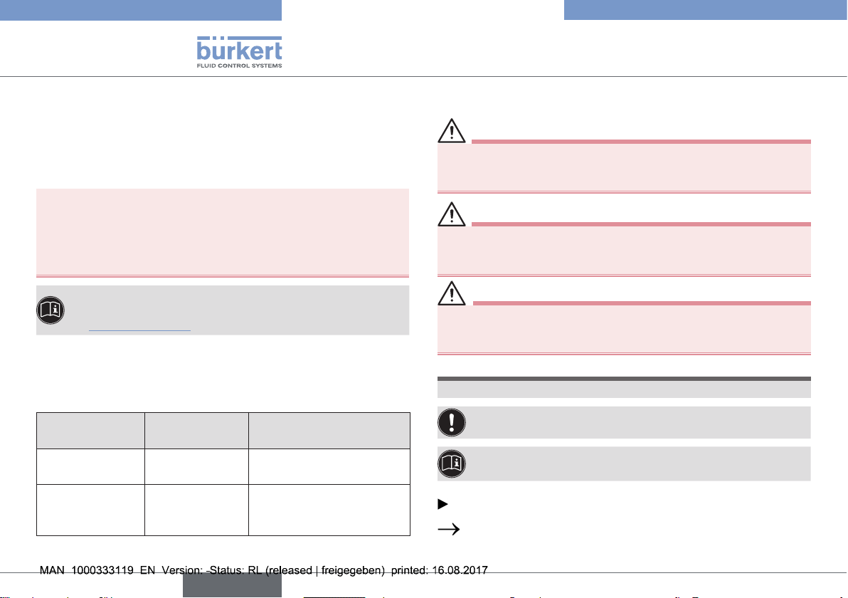
5.1 Max stroke limit
Actuator size D (50 mm), M (70 mm)
Special feature:
• to limit the upper end position
• for control function A only
Actuator size N (90 mm), P (130 mm)
Special feature:
• to limit the upper end position
• for control function A only
Tab. 2: Max stroke limit
5.2 Min and max stroke limit
Actuator size D (50 mm), M (70 mm)
Special feature:
• to limit the upper and lower end
position
• with optical position indicator
• for incoming ow under seat only
Actuator size N (90 mm), P (130 mm)
Special feature:
• to limit the upper and lower end
position
• with optical position indicator
• for incoming ow under seat only
• pilot pressure reduction for actuator
size P (130) with control function I
Tab. 3: Min and max stroke limit
English
7
Page 8
Type 2060, 2061, 2063, 2064, 2065
Overview of options
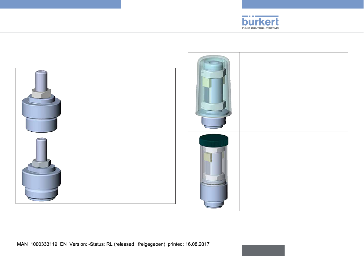
5.3 Threaded nipple for inductive proximity switch M12 x 1
Actuator size D (50 mm), M (70 mm)
Special feature:
• for control function A only
• for upper end position feedback
Actuator size N (90 mm), P (130mm)
Special feature:
• for control function A only
• for upper end position feedback
Tab. 4: Threaded nipple for inductive proximity switch M12 x 1
5.4 Mounting bracket for two inductive proximity switches M12 x 1
Actuator size D (50 mm), M (70 mm)
Special feature:
• upper and lower end position
feedback
Actuator size N (90 mm), P (130 mm)
Special feature:
• upper and lower end position
feedback
Tab. 5: Mounting bracket for two inductive proximity
switches M12 x 1
8
English
Page 9

Type 2060, 2061, 2063, 2064, 2065
Option: max stroke limit
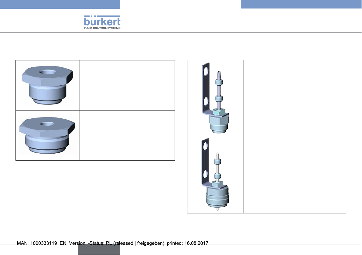
5.5 Electrical position indicator Type 8697 (with adaptation)
Actuator size D (50 mm),
M (70 mm)
Special feature:
+
+
Tab. 6: Electrical position indicator Type 8697 (with adaptation)
• upper and lower end
position feedback
• with optical position
indicator
Actuator size N (90 mm),
P (130 mm)
Special feature:
• upper and lower end
position feedback
• with optical position
indicator
6 OPTION: MAX STROKE LIMIT
WARNING!
Risk of injury from forcibly ejected parts.
If this option is used with incoming medium ow over seat,
there is a danger that parts of the device could be forcibly
ejected by strong opening impacts.
▶ Use the option with incoming ow under seat only.
Use the max stroke limit option only with:
• Control function A.
A
C
B
E
D
A
Transparent cap
B
Position indicator
C
Actuator cover
D
Spindle extension
E
O-ring
Fig. 1: Description of the parts, actuator size D, M, N and P
Pilot air port 2
Pilot air port 1
English
9
Page 10

Type 2060, 2061, 2063, 2064, 2065
Option: max stroke limit
6.1 Before installation
DANGER!
Risk of injury from high pressure and discharge of medium.
▶ Before working on the system or device, switch o the pres-
sure and vent or drain lines.
→ Interrupt the ow of medium.
→ Switch o the pilot air.
→ Empty the valve body.
A
→ Unscrew the transparent cap
DANGER!
Risk of injury from high pressure.
Without the transparent cap, the actuator blows freely upward
when the pilot pressure is applied to the wrong connection.
▶ Apply the pilot pressure for control functions A and I only on
pilot air port 1.
→ To remove the optical position indicator
to the upper end position:
Apply the pilot pressure to connection 1.
→ Unscrew the optical position indicator
extension.
from the actuator cover C.
B
move the actuator
B
from the spindle
6.2 Installation of the max stroke limit
1
2
3
C
Fig. 2: Installation of the max stroke limit
→ Screw the threaded nipple
Observe tightening torques: Actuator D and M: 20 Nm.
→ Turn the threaded spindle
→ Secure the threaded spindle
→ Check the valve for function and leaks.
Actuator cover
C
Required parts:
1
Threaded spindle
Nut
2
Threaded nipple
3
3
into the actuator cover C.
Actuator N and P: 25 Nm.
1
to adjust the upper end position.
1
with nut 2.
10
English
Page 11

Type 2060, 2061, 2063, 2064, 2065
Option: Min and max stroke limit
7 OPTION: MIN AND MAX STROKE
LIMIT
WARNING!
Risk of injury from forcibly ejected parts.
If this option is used with incoming medium ow over seat,
there is a danger that parts of the device could be forcibly
ejected by strong opening impacts.
▶ Use the option with incoming ow under seat only.
Use the max stroke limit option only with:
• Incoming ow under seat.
A
C
B
E
D
A
Transparent cap
B
Position indicator
C
Actuator cover
D
Spindle extension
E
O-ring
Fig. 3: Description of the parts, actuator size D, M, N and P
Pilot air port 2
Pilot air port 1
7.1 Before installation
DANGER!
Risk of injury from high pressure and discharge of medium.
▶ Before working on the system or device, switch o the pres-
sure and vent or drain lines.
→ Interrupt the ow of medium.
→ Switch o the pilot air.
→ Empty the valve body.
A
→ Unscrew the transparent cap
DANGER!
Risk of injury from high pressure.
Without the transparent cap, the actuator blows freely upward
when the pilot pressure is applied to the wrong connection.
▶ Apply the pilot pressure for control functions A and I only on
pilot air port 1.
→ Control function A and I:
To remove the optical position indicator
to the upper end position:
Apply the pilot pressure to pilot air port 1 (one pressure pulse
is sucient for control function I).
→ Unscrew the position indicator
→ For actuator size N and P:
Check the position of the O-ring
reposition it on the base.
from the actuator cover C.
B
move the actuator
B
from the spindle extension D.
E
and if necessary
English
11
Page 12

Type 2060, 2061, 2063, 2064, 2065
Option: Min and max stroke limit
7.2 Installation of the min and max stroke limit, actuator size D and M
Actuator cover
8
4b
4a
7
Fig. 4: Installation of the min and max stroke limit, actuator D
and M
3
→ Fit O-ring
→ Lubricate pipe
in the recess in the pipe 2.
2
and spindle 1 with e.g. multi-silicone
grease OKS 1110.
C
6
D
5
1
2
3
D
C
Spindle extension
(actuator)
Required parts:
Spindle (stroke limit)
1
Pipe
2
O-ring 10 x 2
3
4a
4b
5
Bar
Cylinder head screw M6 x 16
6
Flat seal
7
Hood
8
2 groove M20 x 1.5
1
→ To secure the spindle
, apply a little Loctite 274 in the
threaded hole of the spindle.
→ Screw the spindle
actuator
D
(hexagon socket wrench size 4).
→ Mount at seal
→ Screw nut
4a
→ Lubricate pipe
1
onto the spindle extension of the
7
on pipe 2.
onto the pipe 2 and all the way to the bottom.
2
in the running area of the O-ring 3 with
e.g. multi-silicone grease OKS 1110.
→ Carefully pull the pipe
you do not damage the O-ring
2
over the spindle 1, ensuring that
3
.
→ Control function B:
Place the bar
the actuator cover
5
on the spindle 1 and screw the pipe 2 into
C
(2-edge, wrench size 17).
Observe tightening torque of 20 Nm.
→ Control function A and I:
Screw pipe
2
into actuator cover C (2-edge with wrench
size 17). Observe tightening torque of 20 Nm. Place the
5
bar
on the spindle 1.
→ To secure the cheese-head screw
6
apply a little Loctite 274
to the thread of the cheese-head screw.
→ Screw the cheese-head screw
→ Screw the upper nut
4b
onto the pipe 2.
→ Limit the stroke appropriately with the upper nut
→ Screw on the hood
8
nger-tight.
6
into the spindle 1.
4b
.
→ Check the valve for function and leaks.
12
English
Page 13

Type 2060, 2061, 2063, 2064, 2065
Option: Min and max stroke limit
Note the hardening time of the Loctite before placing the
valve in operation.
7.3 Installation of the min and max stroke limit, actuator size N and P
WARNING!
Risk of injury from forcibly ejected parts.
If this option is used
- with incoming medium ow over seat or
- for actuator size P (130) control function I and a pilot
pressure > 5 bar
there is a danger that parts of the device could be forcibly
ejected by strong opening impacts.
▶ Use the option with incoming ow under seat only.
▶ For actuator size P (130) with control function I, reduce the
pilot pressure to max. 5 bar.
Actuator cover
10
6b
9
6a
1
C
7
D
8
4
Required parts:
2
1
3
2
5
D
3
C
4
5
6a
7
8
9
10
Spindle extension
(actuator)
Pipe
O-ring 15 x 2
O-ring 40 x 2
Spindle (stroke limit)
Spindle coupling
2 nut M30 x 1.5
6b
Cheese-head screw M8 x 25
Bar
Protective pipe (acrylic glass)
Cover
Fig. 5: Installation of the min und max stroke limit, actuator
size N and P
→ To secure the spindle coupling
5
, apply a little Loctite 274 in
the threaded hole.
→ Screw spindle coupling
actuator
→ Screw nut
D
(wrench size 13).
6a
onto the pipe 1 and all the way to the bottom.
5
onto the spindle extension of the
English
13
Page 14

Type 2060, 2061, 2063, 2064, 2065
Option: Threaded nipple
→ Fit O-ring
→ Lubricate spindle
3
in pipe 1.
4
in the running area of the O-ring 2 with
e.g. multi-silicone grease OKS 1110.
→ Lubricate O-ring
2
in the pipe 1 with e.g. multi-silicone
grease OKS 1110.
→ Carefully pull the pipe
you do not damage the O-ring
1
over the spindle 4, ensuring that
2
.
→ Control function B:
Place the bar
screw pipe
8
on the spindle of the stroke limitation 4 and
1
into the actuator cover C.
Observe tightening torque of 25 Nm.
→ Control functions A and I:
Screw pipe
size 24), tightening torque 25 Nm. Place the bar
spindle of the stroke limitation
→ To secure the cheese-head screw
1
into the actuator cover C (2-edge, wrench
4
.
7
apply a little Loctite 274
8
to the thread of the cheese-head screw.
→ Screw the cheese-head screw
→ Screw the upper nut
6b
onto the pipe.
→ Limit the stroke appropriately with the nuts
→ Place protective pipe
→ Screw on the cover
9
10
nger-tight.
7
into the spindle 4.
on pipe 1.
6a 6b
.
→ Check the valve for function and leaks.
Note the hardening time of the Loctite before placing the
valve in operation.
on the
8 OPTION: THREADED NIPPLE
FOR INDUCTIVE PROXIMITY
SWITCH M12 x 1
Use this option only for:
• Control function A.
The option makes it possible to adapt an inductive proximity switch
M12 x 1 (e.g. Turck or Balluf) for ush installation on the actuator.
This option records the upper end position of the actuator. The
target is the spindle extension. The proximity switch is not included
in the scope of supply.
A
C
B
E
D
A
Transparent cap
B
Position indicator
C
Actuator cover
D
Spindle extension
E
O-ring
Fig. 6: Representation of the parts, actuator size D, M, N and P
Pilot air port 2
Pilot air port 1
14
English
Page 15

Type 2060, 2061, 2063, 2064, 2065
Option: Threaded nipple
8.1 Tasks before installation
DANGER!
Risk of injury from high pressure and discharge of medium.
▶ Before working on the system or device, switch o the pres-
sure and vent or drain lines.
→ Interrupt the supply of medium ow.
→ Switch o the pilot air.
→ Empty the valve body.
A
→ Unscrew transparent cap
DANGER!
Risk of injury from high pressure.
Without the transparent cap, the actuator blows freely upward
when the pilot pressure is applied to the wrong connection.
▶ Apply pilot pressure for control function A to connection 1 only.
→ To remove the position indicator
upper end position:
Apply pilot pressure to connection 1.
→ Unscrew position indicator from
o the actuator cover C.
B
, move the actuator to the
B
spindle extension D.
8.2 Installing the threaded nipple
1
Actuator cover
C
C
Required parts:
1
Threaded nipple
Fig. 7: Installing the threaded nipple for inductive proximity
switch
1
→ Screw threaded nipple
tightening torque of 15 Nm.
NOTE!
If the proximity switch is screwed in too deeply, it may be
damaged by the switching movement of the valve.
▶ Align the screw-in depth of the proximity switch with the upper
end position of the actuator (note the switching distance of the
proximity switch).
→ To install the proximity switch, move the actuator to the upper
end position:
Apply pilot pressure to connection 1.
into the actuator cover C. Observe
English
15
Page 16

Type 2060, 2061, 2063, 2064, 2065
Option: Mounting bracket
→ Screw the proximity switch into the threaded nipple
→ Secure the screw-in depth of the proximity switch with a lock
nut (included in the scope of supply of the proximity switch).
→ Check the valve for function and leaks.
1
.
9 OPTION: MOUNTING BRACKET
FOR TWO INDUCTIVE
PROXIMITY SWITCHES M12 x 1
The option makes it possible to adapt two inductive proximity
switches M12 x 1 (for example Turck or Balluf ) for ush installation
on the actuator. The upper and lower end positions of the actuator
are recorded. The target is the switch cam. Lower proximity switches
are not included in the scope of supply.
A
C
B
E
D
A
Transparent cap
B
Position indicator
C
Actuator cover
D
Spindle extension
E
O-ring
Fig. 8: Representation of the parts, actuator size D, M, N and P
Pilot air port 2
Pilot air port 1
16
English
Page 17

Type 2060, 2061, 2063, 2064, 2065
Option: Mounting bracket
9.1 Tasks before Installation
DANGER!
Risk of injury from high pressure and discharge of medium.
▶ Before working on the system or device, switch o the pres-
sure and vent or drain lines.
→ Interrupt the supply of medium ow.
→ Switch o the pilot air.
→ Empty the valve body.
A
→ Unscrew transparent cap
DANGER!
Risk of injury from high pressure!
Without the transparent cap, the actuator blows freely upward
when the pilot pressure is applied to the wrong connection.
▶ Apply the pilot pressure for control functions A and I only on
connection 1.
→ Control functions A and I:
To remove the position indicator
upper end position:
Apply pilot pressure to connection 1 (one pressure pulse is
sucient for control function I).
→ Unscrew position indicator from
→ Check the position of the O-ring
base if required.
o the actuator cover C.
B
, move the actuator to the
B
spindle extension D.
E
and reposition it on the
9.2 Installing the mounting bracket, actuator size D and M
2
1
6
1
Fig. 9: Installing mounting bracket for 2 proximity switches,
actuator size D and M
7
7
4
3
5
C
D
Actuator cover
C
D
Spindle extension
(actuator)
Required parts:
Switch cams
1
Switch spindle
2
Hexagon nut
3
O-ring 5 x 1.5
4
5
Threaded nipple
Mounting bracket
6
Setscrews M3 x 3
7
English
17
Page 18

Type 2060, 2061, 2063, 2064, 2065
Option: Mounting bracket
9.2.1 Installing the mounting bracket
→ Apply a little Loctite 274 in the threaded hole M6 of the
switch spindle
→ Fit O-ring
→ Lubricate switch spindle
silicone grease OKS 1110.
→ Guide threaded nipple
screw into the actuator cover
of 15 Nm.
→ Screw switch spindle
D
using a screwdriver, max. tightening torque: 1Nm.
This is facilitated by moving the actuator into the upper end
position.
Control functions A and I:
Apply pilot pressure to connection 1
(one pressure pulse is sucient for control function I).
→ Fasten the mounting bracket
→ Pull the two switch cams
5
nipple
screw in the setscrews
2
.
4
in the undercut in the threaded nipple 5.
2
and O-ring 4 with e.g. multi-
5
over the switch spindle 2 and
C
. Observe tightening torque
2
onto end of spindle extension thread
6
with nut 3 on the threaded
.
1
onto the switch spindle 2 and
7
(do not tighten).
9.2.2 Installing the proximity switch
The proximity switch is not included in the scope of
supply.
→ Fasten the proximity switch (normally included in the scope
of supply of the proximity switch) into the designated holes in
the mounting bracket using two nuts each
→ Adjust the screw-in depth of the proximity switches to match
the switching distance to the switch cams.
If required, loosen the mounting bracket 6 on the nut 3
and turn it around the actuator axis.
6
.
9.2.3 Positioning of the switch cams
→ Align the position of the lower switch cam 1 to the lower
proximity switch while the actuator is in the lower end
position. Fix switch cam
setscrew
Tightening torque: 0.4...0.6 Nm.
→ Align the position of the upper switch cam
proximity switch while the actuator is in the upper end
position. Fix switch cam
setscrew
Tightening torque: 0.4...0.6 Nm.
→ Check the valve for function and leaks.
Note the hardening time of the Loctite before placing the
valve in operation.
7
.
7
.
1
to the switch spindle 2 using
1
with the upper
1
to the switch spindle 2 using
18
English
Page 19

Type 2060, 2061, 2063, 2064, 2065
Option: Mounting bracket
1
1
7
1
7
2
3
6
Fig. 10: Positioning of the switch cams
For control function A the lower end position is the rest position.
The upper end position is reached by applying a pilot pressure to
connection 1.
For control function B the lower end position is reached by
applying a pilot pressure to connection 1. The upper end position
is the rest position.
For control function I the lower end position is reached by a
pressure pulse on connection 2 and the upper end position is
reached by a pressure pulse on connection 1.
Switch cam (2x)
2
Switch spindle
3
Nut
6
Mounting bracket
7
Setscrew
9.3 Installing the mounting bracket, actuator size N and P
1
6
1
Fig. 11: Installing mounting bracket for 2 proximity switches,
actuator size N and P
2
7
7
3
4
5
C
D
Actuator cover
C
D
Spindle extension
(actuator)
Required parts:
Switch cams
1
Switch spindle
2
Hexagon nut
3
Lip seal 5 x 10 x 4
4
5
Threaded nipple
Mounting bracket
6
Setscrews M3
7
English
19
Page 20

Type 2060, 2061, 2063, 2064, 2065
Option: Mounting bracket
9.3.1 Installing the mounting bracket
→ Apply a little Loctite 274 in the upper threaded hole (M3) of
the spindle extension
actuator into the upper end position.
Control functions A and I:
Apply pilot pressure to connection 1
(one pressure pulse is sucient for control function I).
→ Fit the lip seal
→ Lubricate switch spindle
silicone grease OKS 1110.
→ Screw threaded nipple
Tightening torque: 25 Nm.
→ Screw the switch spindle
spindle extension
torque 1 Nm.
→ Fasten the mounting bracket
nipple.
→ Pull the two switch cams
screw in the setscrews
D
. This is facilitated by moving the
4
in the undercut of the threaded nipple 5.
2
and lip seal 4 with e.g. multi-
5
into the actuator cover C.
2
D
using a screwdriver. Tightening
into the threaded hole of the
6
with nut 3 on the threaded
1
onto the switch spindle 2 and
7
(do not tighten).
9.3.2 Installing the proximity switch
The proximity switch is not included in the scope of
supply.
→ Fasten the proximity switch (normally included in the scope
of supply of the proximity switch) into the designated holes in
the mounting bracket using two nuts each
→ Adjust the screw-in depth of the proximity switches to match
the switching distance to the switch cams.
If required, loosen the mounting bracket 6 on the nut 3
and turn it around the actuator axis.
6
.
9.3.3 Positioning of the switch cams
→ Align the position of the lower switch cam 1 to the lower
proximity switch while the actuator is in the lower end
position. Fix switch cam
setscrew
Tightening torque: 0.4...0.6 Nm.
→ Align the position of the upper switch cam
proximity switch while the actuator is in the upper end
position. Fix switch cam
setscrew
Tightening torque: 0.4...0.6 Nm.
→ Check the valve for function and leaks.
Note the hardening time of the Loctite before placing the
valve in operation.
7
.
7
.
1
to the switch spindle 2 using
1
with the upper
1
to the switch spindle 2 using
20
English
Page 21

Type 2060, 2061, 2063, 2064, 2065
Option: Position feedback Type 8697
1
1
7
1
7
Switch cam (2x)
2
Switch spindle
3
Nut
6
Mounting bracket
7
Setscrew
2
3
6
Fig. 12: Positioning of the switch cams
For control function A the lower end position is the rest position.
The upper end position is reached by applying a pilot pressure to
connection 1.
For control function B the lower end position is reached by
applying a pilot pressure to connection 1. The upper end position
is the rest position.
For control function I the lower end position is reached by a
pressure pulse on connection 2 and the upper end position is
reached by a pressure pulse on connection 1.
10 OPTION: POSITION FEEDBACK
TYPE 8697
A
C
B
E
D
A
Transparent cap
B
Position indicator
C
Actuator cover
D
Spindle extension
E
O-ring
Fig. 13: Representation of the parts, actuator size D, M, N and P
Pilot air port 2
Pilot air port 1
English
21
Page 22

Type 2060, 2061, 2063, 2064, 2065
Option: Position feedback Type 8697
10.1 Tasks before installation
→ Interrupt the supply of medium ow.
→ Switch o the pilot air.
→ Empty the valve body.
→ Unscrew transparent cap
DANGER!
Risk of injury from high pressure!
Without the transparent cap, the actuator blows freely upward
when the pilot pressure is applied to the wrong connection.
▶ Apply the pilot pressure for control functions A and I only on
connection 1.
→ Control functions A and I:
To remove the position indicator
upper end position:
Apply pilot pressure to connection 1
(one pressure pulse is sucient for control function I).
→ Unscrew position indicator from
A
o the actuator cover C.
B
, move the actuator to the
B
spindle extension D.
10.2 Installing the position feedback, actuator size D and M
Actuator cover
C
2
D
Max.
gap
4
5
8
Fig. 14: Installing electrical position feedback Type 8697,
actuator size D and M
3
7
1
6
E
D
C
Spindle extension
(actuator)
O-ring
E
Required parts:
Guide element
1
Switch spindle
2
Switch cam
3
Guide bushing
4
5
Lip seal
O-ring(s)
6
Spacer sleeve
7
Gasket
8
22
English
Page 23

Type 2060, 2061, 2063, 2064, 2065
Option: Position feedback Type 8697
10.2.1 Installing the switch spindle
NOTE!
Lip seal will be damaged if incorrectly installed.
The lip seal is pre-mounted in the guide element and must be
"locked into position" in the undercut.
▶ When installing the switch spindle, do not damage the lip
seal.
2
→ Push switch spindle
→ To secure the switch spindle, apply a little threadlocker
(Loctite 290) in the threaded hole of the switch spindle.
→ Check that the O-ring
→ Screw guide element
tightening torque 8 Nm.
→ Screw switch spindle
this, there is a slot on the upper side. Maximum tightening
torque 1 Nm.
→ Push spacer sleeve
guide element
1
through the guide element 1.
6
is in the correct position.
1
to the actuator cover C. Maximum
2
onto the spindle extension D. To do
7
onto the switch spindle 2 up to the
.
10.2.2 Positioning the switch cam on the
switch spindle
→ Push lower switch cam 3 up to the spacer sleeve 7.
→ Push upper switch cam
the spindle.
Ensure that the gap between the two switch cams is
maximum (see “Fig. 14”).
→ Push electrical feedback onto the actuator.
→ Push electrical feedback all the way down to the actuator and
turn it into the required position.
NOTE!
If the torque is too high when screwing in the fastening screw,
the degree of protection IP65 / IP67 cannot be guaranteed!
▶ The fastening screw may be tightened to a maximum torque
of 0.5 Nm only.
→ Attach the electrical feedback to the actuator using the two
side fastening screws. In doing so, tighten the fastening
screws hand-tight only. Maximum tightening torque 0.5 Nm.
3
until it is 3mm from the start of
English
23
Page 24

Type 2060, 2061, 2063, 2064, 2065
Option: Position feedback Type 8697
10.3 Installing the position feedback, actuator size N and P
Fastening screws
Fig. 15: Tightening fastening screws
Actuator cover
C
2
3
D
4
5
8
Fig. 16: Installing electrical position feedback Type 8697,
actuator size N and P
7
1
6
E
D
C
Spindle extension
(actuator)
O-ring
E
Required parts:
Guide element
1
Switch spindle
2
Switch cam
3
Guide bushing
4
5
Lip seal
O-ring(s)
6
Spacer sleeve
7
Gasket
8
24
English
Page 25

Type 2060, 2061, 2063, 2064, 2065
Option: Position feedback Type 8697
10.3.1 Installing the switch spindle
NOTE!
Lip seal will be damaged if incorrectly installed.
The lip seal is pre-mounted in the guide element and must be
"locked into position" in the undercut.
▶ When installing the switch spindle, do not damage the lip
seal.
2
→ Push switch spindle
→ To secure the switch spindle
(Loctite 290) in the threaded hole of the switch spindle.
→ Check that the O-ring
→ Screw guide element
tightening torque 8 Nm.
→ Screw switch spindle
this, there is a slot on the upper side. Maximum tightening
torque 1 Nm.
→ Push spacer sleeve
guide element
1
through the guide element 1.
2
, apply a little threadlocker
6
is in the correct position.
1
to the actuator cover C. Maximum
2
onto the spindle extension D. To do
7
onto the switch spindle 2 up to the
.
10.3.2 Positioning the switch cam on the
switch spindle
→ Push lower switch cam 3 up to the spacer sleeve 7.
→ Push upper switch cam
the spindle.
Ensure that the gap between the two switch cams is
maximum (see “Fig. 16”).
→ Push electrical feedback onto the actuator.
→ Push electrical feedback all the way down to the actuator and
turn it into the required position.
NOTE!
If the torque is too high when screwing in the fastening screw,
the degree of protection IP65 / IP67 cannot be guaranteed!
▶ The fastening screw may be tightened to a maximum torque
of 0.5 Nm only.
→ Attach the electrical feedback to the actuator using the two
side fastening screws. In doing so, tighten the fastening
screws hand-tight only. Maximum tightening torque 0.5 Nm.
3
until it is 3mm from the start of
English
25
Page 26

Type 2060, 2061, 2063, 2064, 2065
Order numbers
11 ORDER NUMBERS
Fastening screws
Fig. 17: Tightening fastening screws
10.4 Electrical installation
Electrical installation is described in the operating instructions for Type 8697. Operating instructions can be found
on the Internet at: www.burkert.com
Accessories Actuator size Order number
Maximum stroke
limitation
Minimum and
maximum stroke
limitation
Threaded nipple for
inductive proximity
switch
Mounting bracket for
two inductive proximity switches
Electrical position
feedback Type 8697
(adaption set for FA05)
D (50 mm) 699 550
M (70 mm)
N (90 mm) 699 994
P (130 mm)
D (50 mm) 699 986
M (70 mm)
N (90 mm) 699 998
P (130 mm)
D (50 mm) 698 536
M (70 mm)
N (90 mm) 698 537
P (130 mm)
D (50 mm) 699 990
M (70 mm)
N (90 mm) 699 992
P (130 mm)
D (50 mm) 699 551
M (70 mm)
N (90 mm) 580 000
P (130 mm)
26
English
Page 27

Page 28

www.burkert.com
 Loading...