

Page 1

Type 2036
Robolux multiple-way diaphragm valve
Robolux Mehrwege-Membranventil
Vanne à membrane multivoies Robolux
Operating Instructions
Bedienungsanleitung
Manuel d‘utilisation
Page 2

We reserve the right to make technical changes without notice.
Technische Änderungen vorbehalten.
Sous réserve de modifications techniques.
© 2011 - 2013 Bürkert Werke GmbH
Operating Instructions 1312/01_EU-ML_00809601 / Original DE
Page 3

Type 2036
Contents
1. OPERATING INSTRUCTIONS ...................................................................5
1.1. Symbols ..............................................................................................5
1.2. Definition of term / abbreviation ....................................................5
2. AUTHORIZED USE .........................................................................................6
2.1. Restrictions ........................................................................................6
3. BASIC SAFETY INSTRUCTIONS .............................................................6
3.1. Use in Ex area ...................................................................................7
3.2. Special conditions ...........................................................................8
4. GENERAL INFORMATION ...........................................................................9
4.1. Contact address ............................................................................... 9
4.2. Warranty ............................................................................................. 9
4.3. Information on the Internet ............................................................. 9
5. PRODUCT DESCRIPTION ...........................................................................9
5.1. General description ......................................................................... 9
5.2. Device versions ................................................................................. 9
5.3. Options .............................................................................................10
5.4. Valve self-draining ..........................................................................10
5.5. Valve symbols and flow diagrams ................................................ 12
5.6. Valve marking ..................................................................................14
5.7. Intended application area .............................................................15
6. STRUCTURE AND FUNCTION...............................................................15
6.1. Structure ..........................................................................................15
6.2. Position indicator ............................................................................16
7. TECHNICAL DATA ........................................................................................17
7.1. Conformity .......................................................................................17
7.2. Standards .........................................................................................17
7.3. Approvals .........................................................................................17
7.4. Type label .........................................................................................17
7.5. Operating conditions .....................................................................17
7.6. Mechanical data .............................................................................17
7.7. Fluidic data ......................................................................................19
8. ASSEMBLY .......................................................................................................21
8.1. Safety instructions .........................................................................21
8.2. Before installation ...........................................................................21
8.3. Installation ........................................................................................22
8.4. Pneumatic connection .................................................................23
9. ELECTRICAL CONTROL UNIT ............................................................... 25
10. DISASSEMBLY ............................................................................................ 25
11. MAINTENANCE, CLEANING ................................................................. 25
11.1. Safety instructions .......................................................................25
11.2. Servicing intervals ........................................................................26
11.3. Servicing work ..............................................................................26
11.4. Cleaning .........................................................................................26
12. REPAIRS ......................................................................................................... 27
12.1. Safety instructions .......................................................................27
12.2. Replacing the diaphragm ...........................................................27
english
3
Page 4

13. MALFUNCTIONS ........................................................................................ 30
14. SPARE PARTS ............................................................................................. 31
14.1. Order table ....................................................................................31
15. TRANSPORT, STORAGE, PACKAGING .......................................... 32
Type 2036
4
english
Page 5

Type 2036
Operating instructions
1. OPERATING INSTRUCTIONS
The operating instructions describe the entire life cycle of the device.
Keep these instructions in a location which is easily accessible to
every user and make these instructions available to every new owner
of the device.
WARNING!
The operating instructions contain important safety information.
Failure to observe these instructions may result in hazardous
situations.
▶ The operating instructions must be read and understood.
1.1. Symbols
DANGER!
Warns of an immediate danger.
▶ Failure to observe the warning will result in a fatal or serious injury.
WARNING!
Warns of a potentially dangerous situation.
▶ Failure to observe the warning may result in serious injuries or
death.
CAUTION!
Warns of a possible danger.
▶ Failure to observe this warning may result in a moderate or minor
injury.
NOTE!
Warns of damage to property.
▶ Failure to observe the warning may result in damage to the
device or the equipment.
Indicates important additional information, tips and
recommendations.
Refers to information in these operating instructions or in
other documentation.
▶ Indicates an instruction to prevent risks.
→ Designates a procedure which you must carry out.
1.2. Definition of term / abbreviation
In these instructions, the term 'device' always refers to the Robolux
Multiway Diaphragm Valve Type 2036.
In these instructions, the term 'Diaphragm Valve' always refers to the
Robolux Multiway Diaphragm Valve Type 2036.
In these instructions, the abbreviation “Ex” always refers to
“potentially explosive”.
english
5
Page 6
Type 2036
Authorized use
2. AUTHORIZED USE
Improper use of the Robolux Multiway Diaphragm Valve
Type 2036 may represent a hazard to persons, neighboring
equipment and the environment.
The device is designed for controlling the flow-rate of liquid media.
▶ The approved data, the operating conditions and conditions of use
specified in the contract documents, operating instructions and on
the type label are to be observed during use. The designated areas
of application are specified in chapter "5. Product description".
▶ Use the device only in conjunction with third-party devices and
components recommended and authorized by Bürkert.
▶ Correct transportation, storage, and installation, as well as care-
ful use and maintenance are essential for reliable and faultless
operation.
▶ Use the device only as intended.
2.1. Restrictions
If exporting the system/device, observe any existing restrictions.
3. BASIC SAFETY
INSTRUCTIONS
These safety instructions do not make allowance for any
• Contingencies and events which may arise during the installation,
operation, and maintenance of the devices.
• Local safety regulations – the operator is responsible for observing
these regulations, also in relation to the installation personnel.
DANGER!
Risk of injury from high pressure in the equipment/device.
▶ Before working on equipment or device, switch off the pressure
and deaerate/drain lines.
Risk of electric shock.
▶ Before reaching into the device, switch off the power supply
and secure to prevent reactivation.
▶ Observe applicable accident prevention and safety regulations
for electrical equipment.
WARNING!
Risk of injury when opening the actuator.
The actuator contains tensioned springs. If the actuator is opened,
injuries may be caused by the springs jumping out!
▶ The actuator must not be opened.
6
english
Page 7
Type 2036
Basic safety instructions
CAUTION!
Risk of burns.
The surface of the device may become hot during long-term operation.
▶ Do not touch the device with bare hands.
Risk of being crushed by moving spindle ends.
▶ Install transparent cap.
Generally hazardous situations.
To prevent injuries:
▶ Ensure that the system cannot be activated unintentionally.
▶ Installation and repair work may be carried out by authorized
technicians only and with the appropriate tools.
▶ After an interruption in the electrical or pneumatic supply,
ensure that the process is restarted in a defined or controlled
manner.
▶ The device must only be operated when in a perfect condition
and in consideration of the operating instructions.
▶ The general rules of technology must be observed for applica-
tion planning and operation of the device.
To prevent material damage:
▶ Supply only media to the media connections that are specified
in chapter "7. Technical Data" as flow media.
▶ Do not place the valve under mechanical stress (e.g. by placing
objects on it or standing on it).
▶ Do not make any external alterations to the valves. Do not apply
paint to body parts or screws.
3.1. Use in Ex area
Abbreviation “Ex”: see chapter "1.2. Definition of term / abbreviation"
3.1.1. Safety instructions
For operation in Ex area Zone (gas) 1 and 2,
Zone (dust) 21 and 22, the following
applies:
The valve actuator is suitable for use as a Category 2 device for
Zone 1 and 21, non-electrical production equipment.
DANGER!
Danger of explosion caused by electrostatic charge.
Depending on the conductivity of the medium, electrostatic charges
may occur on the valve membrane if plastic bodies are used.
To prevent electrostatic charges in the fluid, the following instructions
must be observed (as per IEC 60079-32-1):
▶ (1) Media with a conductivity ≤ 100 pS/m may only be used if no
flow speeds > 1 m/s occur or if the possibility of the pipe system
running dry is excluded by suitable monitoring.
▶ (2) Media with a conductivity > 100 pS/m and ≤ 1000 pS/m may
only be used if they are liquids without any particles, steam or pure
gases/steam, or if the instructions in (1) are observed.
▶ (3) Media with a conductivity > 1000 pS/m are not subject to any
restrictions.
english
7
Page 8

Type 2036
Basic safety instructions
Further instructions:
▶ The user must ensure that the appliance is used in Zone 1/21 or
2/22 only.
▶ The control unit may restrict use in an explosive atmosphere. Follow
operating instructions for control unit.
▶ Check that any cleaning agents are approved for use in explosive
atmospheres.
3.1.2. Media temperature
DANGER!
▶ If explosive media are used this can cause additional explosion risks.
▶ If media temperatures are used between 130 °C and 150 °C, the
temperature class T3 / 200 °C applies (dust).
Media temperature max. 130 °C
3.1.3. Marking Ex area
PTB 13 ATEX D103 X
II 2G c IIC T4
II 2D c T135°C
Warning: Not valid when Non-Ex devices added.
The Ex marking is not valid if Non-Ex devices are added.
3.2. Special conditions
→ To ensure potential equalization, ground the valve body to the
pipe system using an electrically conductive connection.
DANGER!
Danger of explosion caused by electrostatic charge.
In the event of a sudden discharge from electrostatically charged
devices or individuals there is a risk of an explosion in the Ex area.
▶ Implement suitable measures to ensure that there are no
electrostatically charges in the Ex area (see also "3.1. Use in Ex
area").
▶ Clean the device surface by gently wiping it with a damp or anti-
static cloth only.
▶ Earth the actuator and valve body.
▶ If a plastic body is used, earth the actuator separately.
Ambient temperature range: 0 °C ≤ Tamb ≤ 60 °C
Do not open actuator. Spring loaded cover.
Fig. 1: Marking Ex area
8
english
Page 9

Type 2036
General information
4. GENERAL INFORMATION
4.1. Contact address
Germany
Bürkert Fluid Control Systems
Sales Center
Christian-Bürkert-Str. 13-17
D-74653 Ingelfingen
Tel. + 49 (0) 7940 - 10 91 111
Fax + 49 (0) 7940 - 10 91 448
Email: info@de.buerkert.com
International
Contact addresses can be found on the final pages of the printed
operating instructions.
And also on the Internet at: www.burkert.com
4.2. Warranty
The warranty is only valid if the diaphragm valve is used as intended in
accordance with the specified application conditions.
4.3. Information on the Internet
The operating instructions and data sheets for Types 2036 can be
found on the Internet at:
www.burkert.com
5. PRODUCT DESCRIPTION
5.1. General description
The manually or pneumatically operated Robolux Multiway Diaphragm Valves
of ultra-pure, sterile, aggressive or abrasive media. They allow for
optimal collection, draining or distribution of critical process media.
1) In the following text the Robolux Multiway Diaphragm Valve is
referred to as 'diaphragm valve' for brevity's sake.
5.2. Device versions
The diaphragm valve can be adapted to very different usage conditions on account of its modular design.
Depending on the connection size of the diaphragm valves three
construction sizes are available (RV5O, RV7O, RV110).
The valve body is made from a stainless steel block. For certain
usage conditions valve bodies made of plastic (PVDF or PP) are
available.
High-quality diaphragms ensure complete separation of the critical
medium from the actuator.
1)
have been designed as a system for the control
Observe instructions on operation in an explosion-risk (Ex)
area. See chapter "3.1. Use in Ex area".
english
9
Page 10

Type 2036
Product description
The diaphragm valves can be used for a large variety of control
functions. Accordingly, there is a very wide range of configuration
variations. Depending on the function the valve can have one, two or
three actuators.
Pneumatically operated
actuator
Diaphragm
Valve body
5.3. Options
The following options are available for controlling the actuators and
feedback of the different switching positions.
• Feedback head Type 8685 with up to four position feedback indicators in the versions 24 V DC, AS-Interface and EExi.
• Control head Type 8686 with up to two pilot valves and position
indicators in the versions 24 V DC, AS-Interface and EExi.
5.4. Valve self-draining
The way in which self-draining takes place varies according to the
valve type. It is very important to know the flow paths for each individual valve before the port / connection (marked with A, B, C or D)
for draining is selected.
Contact your Bürkert sales office or our Sales Center, email:
info@de.buerkert.com if you have any queries.
Fig. 2: Diaphragm valve, structure and description
10
english
Page 11

Type 2036
Product description
Installation positions for self-drainage:
A
B
3C2S / 4C2S
drainage connection
B (D)
Fig. 3: Self-draining - 3C2S / 4C2S
C
A
B
A
D
B
A
B
C
3C2S / 4C2S
drainage connection
C (A)
C
C
Installation positions for self-drainage:
A
B
C
D
4C4S CF
drainage connection
D
Fig. 4: Self-draining - 4C4S CF
B
D
A
C
english
11
Page 12

Type 2036
Product description
Installation positions for self-drainage:
C
D
A
4C4S DFP
drainage connection
A (C)
Fig. 5: Self-draining - 4C4S DFP
B
A
B
A
4C4S DFP
drainage connection
B (D)
D
C
5.5. Valve symbols and flow diagrams
D
C
B
3 connections, 2 seats
3C2S
Seat
U1
A
U1 U2
B
Seat
U2
C
4 connections, 2 seats
4C2S
Seat
U1
D
A
U1 U2
B
Seat
U2
C
12
Fig. 6: Valve symbols and flow diagrams - 3C2S / 4C2S
english
Page 13

Type 2036
Product description
C
Seat
U1
4 connections, 4 seats
4C4S CF
upper side lower side
A
D
L2
L1
Seat
B
U2
B
B
Seat
L1
A
D
A
D
U1
U2
C
Seat
L2
4 connections, 4 seats
4C4S DFP
upper side lower side
D
A
C C
D
C
Seat
U1
Seat
B
L2
U2
A
U1
Seat
L1
D
B
L1
C
U2
Seat
L2
B
Fig. 7: Valve symbols and flow diagrams - 4C4S CF
Fig. 8: Valve symbols and flow diagrams - 4C4S DFP
english
13
Page 14

Type 2036
Product description
5.6. Valve marking
Type label
Marking and warning
notices in Ex area
Actuator orientation
marking
Port connection
markings
Valve body labeling
Bürkert company logo, Orifice and connection dimensions
Material, charge, manufacturing order and serial No.
Fig. 9: Valve marking
5.6.1. Marking and warning notices in Ex
area
See chapter "Use in Ex area" on page 7.
5.6.2. Type label
Company logo
Identification
number
Connection dimensions
Fig. 10: Type label
Date of manufacture
Type - Size - Design
- Diaphragm material
Actuator 1 - Actuator
2 - Pilot pressure
Max. medium pressure medium temperature
5.6.3. Port connection markings
All port connections are provided with letters corresponding to the
flow diagrams (see chapter "5.5. Valve symbols and flow diagrams").
5.6.4. Actuator orientation marking
The actuator has a marking close to connection A as an aid to
ensure correct assembly.
14
Fig. 11: Actuator orientation marking
english
Page 15
Type 2036
Structure and function
5.7. Intended application area
The diaphragm valve has been designed for use with soiled and
aggressive media which do not corrode the body and the seal
materials.
Observe the maximum pressure range according to the
type label.
• Ultra-pure, sterile, aggressive or abrasive media.
• Highly viscous media.
Observe instructions on operation in an explosion-risk (Ex)
area. See chapter "3.1. Use in Ex area".
5.7.1. Application areas
e.g. plant construction
luxury food and food processing industry
bottling plant
chemical engineering
pharmaceutics
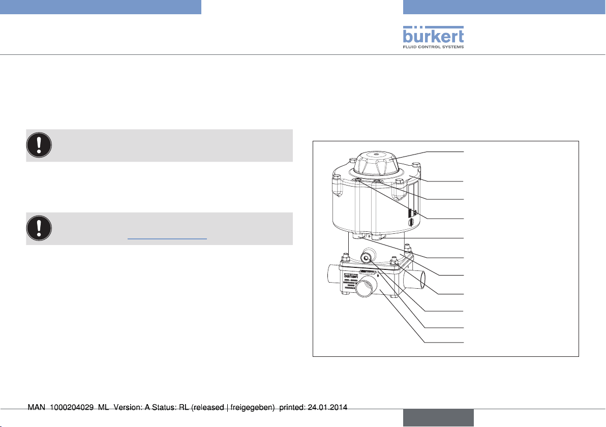
6. STRUCTURE AND FUNCTION
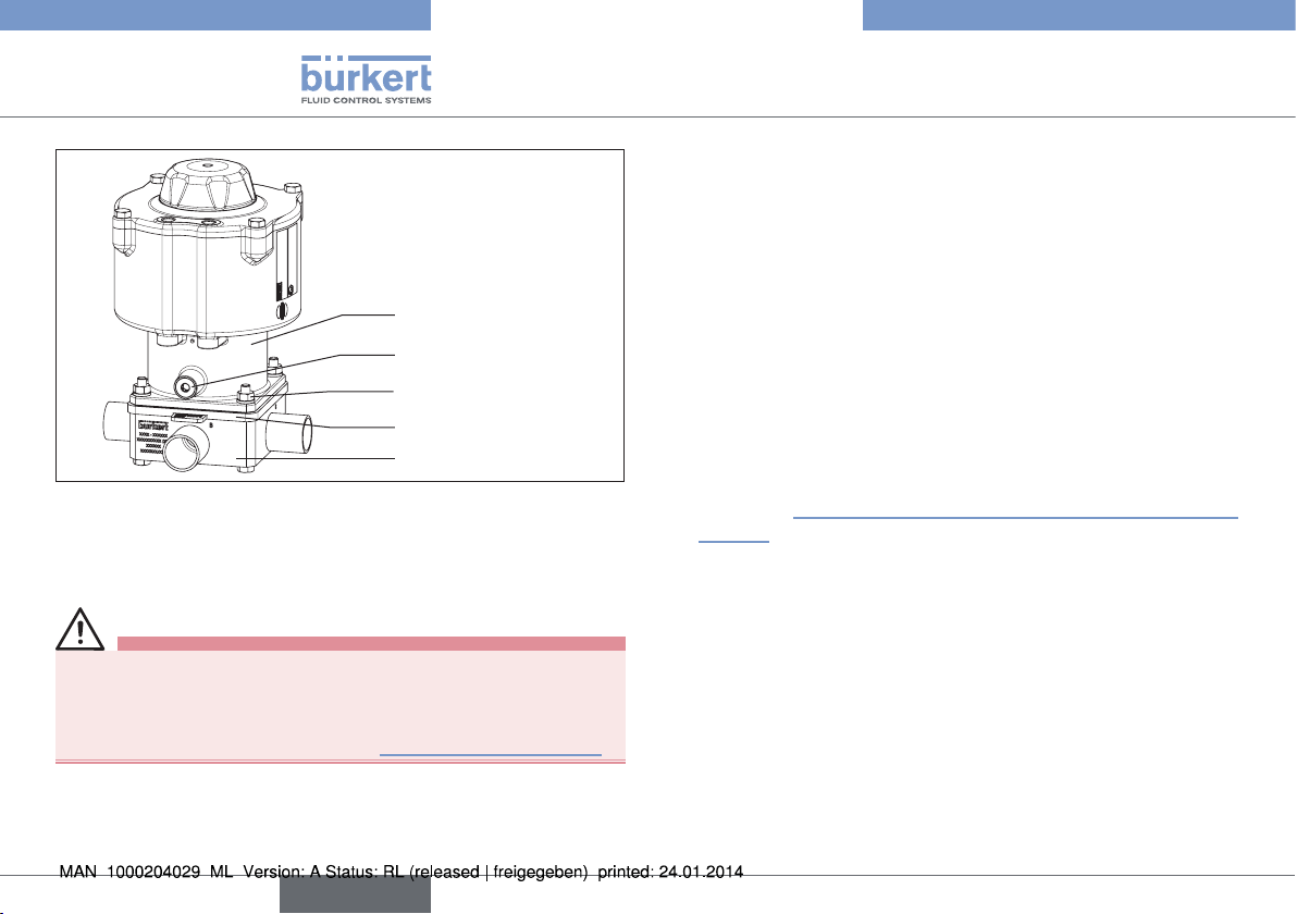
6.1. Structure
The diaphragm valve consists of a pneumatically operated piston
actuator, diaphragm and multi-port valve body.
Transparent cap with
position indicator
Actuator cover
Pilot air port 4
Pilot air port 2
Pilot air port 3
Pilot air port 1
Actuator body
Body screws
Guide pin
Diaphragm
Valve body
Fig. 12: Piston-controlled diaphragm valve, structure and
description
english
15
Page 16
Type 2036
1(P)
2(A)
1(P)
2(B)
Structure and function
6.1.1. Actuator
The actuator has two actuator chambers that can be controlled
independently of each other and act on one body seat each (double
action). Where only one actuator is in operation only one actuator
chamber is equipped with the internal functional parts.
Spring force (CFA, NC) or pneumatic pilot pressure (CFB, NO)
generates the closing force of the actuator.
The force is transmitted onto the corresponding pressure piece and
the diaphragm in each case via a spindle connected to the actuator
piston.
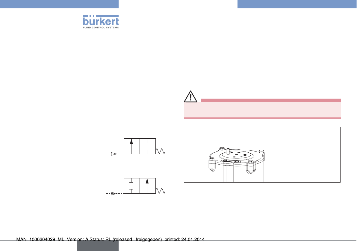
6.1.2. Control functions (CF)
Control function A, NC (CFA)
Closed by spring force in rest
position
Control function B, NO (CFB)
Opened by spring force in rest
position
6.2. Position indicator
The position of both actuator chambers is signaled via position indicators. Two positions are possible:
• Short protrusion of the position indicator → valve closed.
• Long protrusion of the position indicator → valve open
CAUTION!
Risk of being crushed by moving spindle ends.
▶ Install transparent cap.
Long protrusion
Short protrusion
Transparent cap
removed
Fig. 13: Position indicator
16
english
Page 17
Type 2036
Technical Data
7. TECHNICAL DATA
7.1. Conformity
The diaphragm valve of Type 2036 comply with EC Directives in
accordance with the EC Declaration of Conformity.
7.2. Standards
The applied standards on the basis of which compliance with the EC
Directives is confirmed are listed in the EC type examination certificate
and/or the EC Declaration of Conformity.
7.3. Approvals
The product is approved for use in zone 1 and 21 in accordance
with ATEX directive 94/9/EC category 2 GD.
Observe instructions on operation in an explosion-risk (Ex)
area. See chapter "3.1. Use in Ex area".
7.4. Type label
See chapter "5.6. Valve marking".
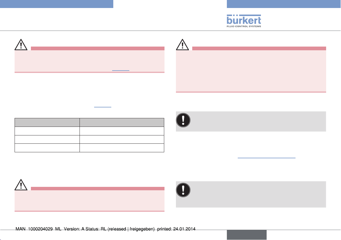
7.5. Operating conditions
Observe permitted pressure ranges given on the type label
of the device.
2)
Ambient temperature -10 − +60 °C
higher temperatures on request
Relative humidity max. 80 % (non-condensing)
7.6. Mechanical data
Dimensions see data sheet
Materials
Body material stainless steel: 1.4435/316L
(other materials on request)
Diaphragm EPDM, Advanced PTFE/EPDM, FKM,
silicone
Actuator
Body stainless steel precision casting 1.4308
Pressure piece PPS (Polyphenylensulfid) and V2A
2) If a control unit or a pilot valve is used, the max. ambient
temperature is +55 °C.
english
17
Page 18

Type 2036
Technical Data
Connections
Port connections welded spigots
DIN EN ISO 1127 / ISO 4200) /
DIN 11866 Series 2,
DIN 11850 Series 2 / DIN 11866 Series A
ASME BPE / DIN 11866 Series C
Clamp
DIN 32676 Series A (DIN pipe)
DIN 32676 Series B (ISO pipe)
ASME BPE
(other connections on request)
Pilot air port G1/8
Surface quality interior Ra 0.6 µm passivated
exterior Ra 1.6 µm machined
optional electro-polished
(other surface finishes on request)
Installation position any position; preferably connection B
downwards; for self-drainage see chapter
"5.4. Valve self-draining"
The service life of the device depends heavily on the conditions of use.
Especially the service life of the diaphragm depends very heavily on
the conditions of use, such as the medium, temperatures, switching
frequency, pressure etc., and may vary widely in individual cases.
7.6.1. Diaphragm
The diaphragm seals the valve. It must be selected with care. The
choice of material should be made bearing in mind the process
medium, the temperature and the mechanical boundary conditions
(e.g. operating pressure, switching frequency etc.).
The standard materials are contained in the following table.
For conformity with FDA CFR 21 Para. 177.2600 or Para. 177.1550
and USP VI certification, see "Tab. 1: Diaphragm materials".
Diaphragm
material
EPDM AD Peroxide-vulca-
Advanced
PTFE /
EPDM
FKM KL Fluorinated
Silicone SK Platinum-sta-
Tab. 1: Diaphragm materials
Code Description of
material
nized ethylenepropylene
rubber
EK Advanced PTFE
laminated
EPDM
rubber
bilized silicone
rubber
Use FDA USP
VI
Oxidizing
chemicals,
steam and hot
water
Most chemicals and
acids
Acids and
mineral oils
Aliphatic oils x x
x x
x x
x
18
english
Page 19
Type 2036
Technical Data
7.7. Fluidic data
Media
flow media ultra-pure, sterile, aggressive,
(see also chapter "7.6.1. Diaphragm")
Media pressure see chapter "7.7.1. Pressure ranges"
Media temperature
stainless steel/EPDM +5 to +130 °C
(max. +143 °C for 60 min.)
stainless steel/
Advanced PTFE +5 to +90 °C
(no steam sterilization)
stainless steel/FKM +5 to +130 °C
(dry heat up to max. +143 °C)
stainless steel/silicone +5 to +130 °C
(dry heat up to max. +143 °C)
Observe instructions on operation in an explosion-risk (Ex)
area. See chapter "3.1. Use in Ex area".
Pilot medium Neutral gases, dry air (min. 10 K below
min. operating temperature), preferably
unoiled
Pilot pressure
3) Pressure values [bar]: Overpressure with respect to atmospheric
pressure
3)
6 – 10 bar (RV50, RV70)
6 – 7 bar (RV110)
from 4.2 bar (with reduced medium
pressure) on request
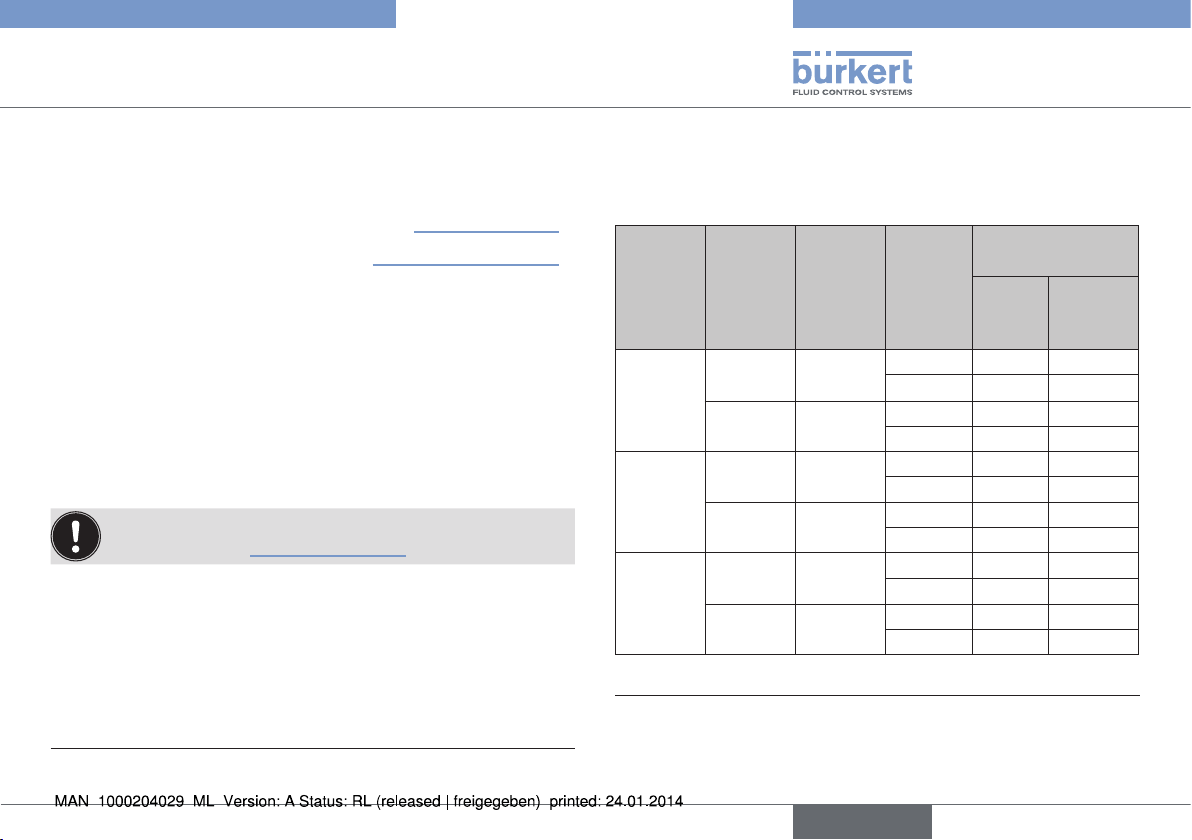
7.7.1. Pressure ranges
Pilot pressure and operation pressure for CFA, NC
Values for stainless steel body
max. operation
pressure [bar]
EPDM,
FKM,
Size
Actuator
version
Pilot
pressure
4)
[bar]
Test
criterion
5)
Silicone
Static 7.5 7.5
Dynamic 6.5 5.5
Static 5.0 3.5
Dynamic 4.0 2.5
Static 8.0 8.0
Dynamic 6.0 6.0
Static 5.5 6.0
Dynamic 3.5 4.0
Static 7.0 7.5
Dynamic 5.0 5.5
Static 5.0 5.0
Dynamic 3.0 3.0
RV50
RV70
RV110
D11
D1x; Dx1
6 – 10
D55 4.2 – 10
D11
D1x; Dx1
6 – 10
D55 4.2 – 10
D11
D1x; Dx1
6 – 7
D55 4.2 – 7
Tab. 2: Pilot pressure and operation pressure
4) See type label.
5) Pressure values [bar]: Overpressure with respect to atmospheric
pressure
english
5)
Advanced
PTFE/
EPDM
19
Page 20
Type 2036
Technical Data
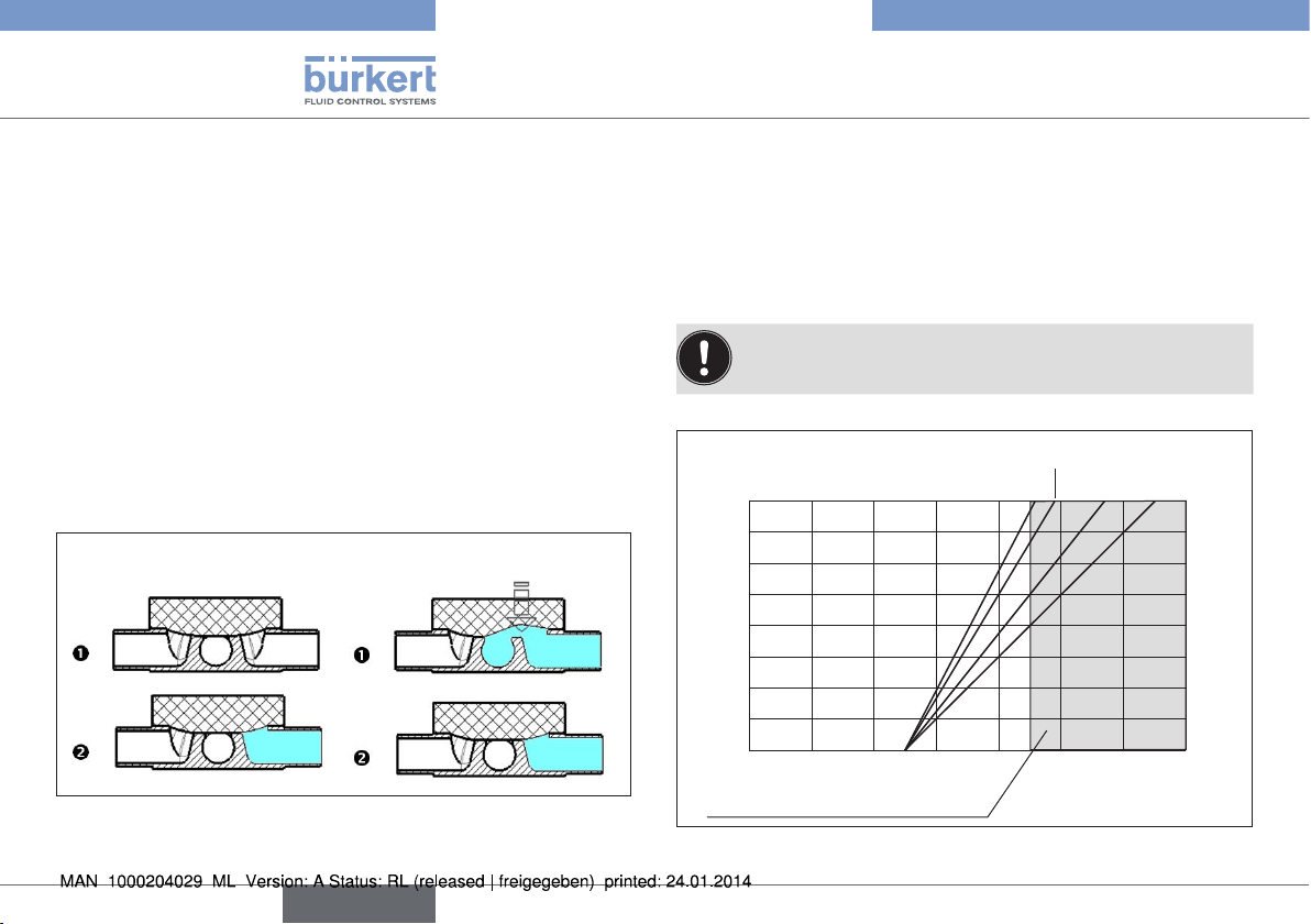
Remarks
Static leak-tightness:
Valve is closed (diaphragm is in contact with the body seat). One
side of the body seat is under pressure. At the given pressure no
leakage takes place via the body seat.
Dynamic leak-tightness:
Valve is open and the medium is flowing through it. The downstream
flow is only slightly throttled by components placed downstream.
Both sides of the body seat are under pressure. The valve is closed
(CFA, NC via spring force; CFB, NO via pilot pressure). At the
given pressure the valve closes onto the body seat and the seal is
complete.
Static leak-tightness:
Dynamic leak-tightness:
Fig. 14: Static and dynamic leak-tightness
Pilot pressure and operation pressure for CFB, NO
The following graphs illustrate the required minimum pilot pressure
depending on the medium pressure for control function B.
Permitted pilot pressure range: 2 – 7 bar.
The pilot pressure should be selected to be as low as possible to reduce wear on the diaphragm.
RV50/RV110
static
RV70
8
7
6
5
4
3
Medium pressure [bar]
2
1
0
0 1 2 3 4 5 6 7
Range for valves with control unit
static
RV70
dynamic
Pilot pressure [bar]
RV50/RV110
dynamic
Fig. 15: Pilot pressure depending on the medium pressure
20
english
Page 21

Type 2036
Assembly
8. ASSEMBLY
8.1. Safety instructions
DANGER!
Risk of injury from high pressure in the equipment/device.
▶ Before working on equipment or device, switch off the pressure
and deaerate/drain lines.
WARNING!
Risk of injury from improper assembly.
▶ Installation must only be carried out by authorized technicians
and with the appropriate tools.
Risk of injury from unintentional activation of the system and
uncontrolled restart.
▶ Secure system from unintentional activation.
▶ Following assembly, ensure a controlled restart.
8.2. Before installation
→ Before connecting the valve, ensure the pipelines are flush.
→ Pay attention to the flow direction.
8.2.1. Installation position
• The piston-controlled diaphragm valve can be installed in any
position, preferably with connection B downwards.
• Installation for self-drainage of the body:
see chapter "5.4. Valve self-draining"
8.2.2. Preparatory work
→ Clean pipelines (sealing material, swarf, etc.).
→ Support and align pipelines.
Devices with welded body
NOTE!
Damage to diaphragm or actuator.
▶ Before welding in the body disassemble the actuator and
diaphragm.
Remove the actuator from the valve body:
→ Move the actuator to the upper actuator position (CFA, NC: by
applying pilot pressure; CFB, NO: by removing the pilot pressure).
→ Mark the position of the actuator in relation to the valve body.
→ Unscrew the four body screws that connect the valve body with
the actuator. Remove the actuator and the diaphragm.
english
21
Page 22
Actuator
Guide pin
Body screws
Diaphragm
Valve body
Fig. 16: Assembly
8.3. Installation
WARNING!
Risk of injury from improper assembly.
Non-compliance with the tightening torques is dangerous due to
possible discharge of medium and possible release of pressure.
▶ Observe the tightening torque (see "Tab. 3: Tightening torque").
Type 2036
Assembly
8.3.1. Installing the body
Welded body
→ Weld valve body in pipeline system.
Other body designs
→ Connect body to pipeline.
8.3.2. Installing the actuator (welded body)
→ Move the actuator to the upper actuator position (CFA, NC: by
applying pilot pressure; CFB, NO: by removing the pilot pressure).
→ Put the actuator / diaphragm on the body with correct alignment
(so that the markings made previously align). In the case of RV110
the four spacer sleeves must be inserted in the designated body
holes (see "Fig. 20: Disassembly / assembly the diaphragm" on
page 28).
→ Tighten the diagonally opposed body screws / nuts until there
is visible, uniform mechanical contact between the valve body,
diaphragm and actuator.
→ Switch the diaphragm valve twice.
22
english
Page 23
Type 2036
Assembly
WARNING!
Risk of injury from discharge of medium and release of
pressure.
▶ Tighten the body screws sufficiently (see "Tab. 3").
→ Move the actuator to the lower actuator position (CFA, NC: by
removing pilot pressure; CFB, NO: by applying the pilot pressure).
→ Without applying pilot pressure, tighten the body screws to the
permitted tightening torque (see "Tab. 3").
Size Tightening torque [Nm]
RV50 6
RV70 17
RV110 30
Tab. 3: Tightening torque
8.4. Pneumatic connection
DANGER!
Risk of injury from high pressure in the system.
▶ Before disconnecting lines and valves, turn off the pressure and
vent the lines.
WARNING!
Risk of injury from unsuitable connection hoses.
Hoses which cannot withstand the pressure and temperature
range may result in hazardous situations.
▶ Use only hoses which are authorized for the indicated pressure
and temperature range.
▶ Observe the data sheet specifications from the hose manufacturers.
8.4.1. Connection of the pilot medium
To comply with the degree of protection IP65 / IP67 on the
pilot air port which is not required (for CFA, NC and CFB,
NO), install an exhaust air line in the dry area.
For the assignment of pilot air ports refer to the installation and dimensional drawing included with delivery of the valve. Compare also the
information given in chapter "6. Structure and function".
The use of pneumatic hose with a minimum size of 6/4 is recommended.
For longer hose lengths the hose cross-sections should be adapted
accordingly.
In aggressive surroundings and in situations where moisture
could enter the actuator via the exhaust air port or muffler
the exhaust air should be collected and ducted to a noncritical location.
english
23
Page 24

Type 2036
Assembly
Control function A:
→ Connect the control medium to the pilot air port 1 and/or 3
(see "Fig. 17").
Control function B:
→ Connect the control medium to the pilot air port 2 and/or 4
(see "Fig. 17").
Silencer
→ Connect the silencer into the free air discharge connection
(see "Fig. 17").
Actuator 1
(left)
Pilot air port
2 (P2)
Pilot air port
1 (P1)
Actuator 2
(right)
Pilot air port
4 (P4)
Pilot air port
3 (P3)
Actuator
version
D11, D55
CFA/CFA
(NC/NC)
D12
CFA/CFB
(NC/NO)
D21
CFB/CFA
(NO/NC)
D22
CFB/CFB
(NO/NO)
Tab. 4: Pneumatic connection for actuator versions
CFA, NC : Valve normally closed by spring action
CFB, NO : Valve normally open by spring action
Numbers for
actuator 1
Actuator 1 Actuator 2
CF Connection CF Connection
Pilot air P1
CFA,
NC
CFA,
NC
CFB,
NO
CFB,
NO
indicating
P2: air discharge
Pilot air P1
P2: air discharge
Pilot air P2
P1: air discharge
Pilot air P2
P1: air discharge
CFA
CFB
CFA
CFB
Pilot air P3
P4: air discharge
Pilot air P4
P3: air discharge
Pilot air P3
P4: air discharge
Pilot air P4
P3: air discharge
Numbers for
indicating
actuator 2
Fig. 17: Pneumatic connection
24
Fig. 18: Cover film
english
Page 25

Type 2036
Electrical control unit
9. ELECTRICAL CONTROL UNIT
The electrical connection of the pilot valve / control unit is
described in the operating instructions for the pilot valve /
control unit.
Observe instructions on operation in an explosion-risk (Ex)
area. See chapter "3.1. Use in Ex area".
10. DISASSEMBLY
DANGER!
Risk of injury from discharge of medium and release of
pressure.
It is dangerous to remove a device which is under pressure due to
the sudden release of pressure or discharge of medium.
▶ Before removing a device, switch off the pressure and vent the
lines.
If the valve is to be reused after removal, the actuator must
be removed before disassembly where welded bodies are
involved. For this, refer to the assembly instructions.
Procedure:
→ Loosen pneumatic connection.
→ Remove device.
11. MAINTENANCE, CLEANING
11.1. Safety instructions
DANGER!
Risk of injury from high pressure in the equipment/device.
▶ Before working on equipment or device, switch off the pressure
and deaerate/drain lines.
Risk of electric shock.
▶ Before reaching into the device, switch off the power supply
and secure to prevent reactivation.
▶ Observe applicable accident prevention and safety regulations
for electrical equipment.
WARNING!
Risk of injury from improper maintenance.
▶ Installation must only be carried out by authorized technicians
and with the appropriate tools.
Risk of injury from unintentional activation of the system and
uncontrolled restart.
▶ Secure system from unintentional activation.
▶ Following maintenance, ensure a controlled restart.
english
25
Page 26

Type 2036
Maintenance, Cleaning
11.2. Servicing intervals
Check the diaphragm valves regularly for proper operation in terms
of assembly, installation and operation. Take the following factors into
account when planning servicing intervals:
• Operational conditions (amount of usage, improper usage),
• manufacturer's specifications in the technical documentation (e.g.
mechanical service life,
• major system modifications.
11.3. Servicing work
Do not repair the device yourself, but replace it with an
equivalent device. Repairs may be performed by the manufacturer only.
11.3.1. Actuator
The actuator of the diaphragm valve is maintenance-free provided it
is used according to these operating instructions.
11.3.2. Wearing parts of the diaphragm valve
The diaphragm is subject to wear.
→ If leakage occurs replace the diaphragm (see chapter "12. Repairs").
A bulging diaphragm may reduce the flow rate.
The replacement of the diaphragm is described in chapter
"12. Repairs".
11.4. Cleaning
NOTE!
Avoid causing damage with cleaning agents.
▶ Before cleaning, check that the cleaning agents are compatible
with the device materials.
Observe instructions on operation in an explosion-risk (Ex)
area. See chapter "3.1. Use in Ex area".
Actuator
Clean the actuator surface using a moist cloth. Only use cleaning
agents that do not attack the actuator surface.
Body / Diaphragm
The bodies are suitable for CIP. Clean the valves using cleaning
agents that do not attack the body and diaphragm materials. Avoid
cleaning agents with high pH values.
26
english
Page 27

Type 2036
Repairs
12. REPAIRS
12.1. Safety instructions
DANGER!
Risk of injury from high pressure in the equipment/device.
▶ Before working on equipment or device, switch off the pressure
and deaerate/drain lines.
Risk of electric shock.
▶ Before reaching into the device, switch off the power supply
and secure to prevent reactivation.
▶ Observe applicable accident prevention and safety regulations
for electrical equipment.
WARNING!
Risk of injury from improper repair.
▶ Installation must only be carried out by authorized technicians
and with the appropriate tools.
▶ Observe the tightening torques.
▶ On completion of the work check valve for leaks and function.
Risk of injury from unintentional activation of the system and
uncontrolled restart.
▶ Secure system from unintentional activation.
▶ Following maintenance, ensure a controlled restart.
12.2. Replacing the diaphragm
Required spare part
• Diaphragm
12.2.1. Disassembly of the actuator and
diaphragm
→ Move the actuator to the upper actuator position (CFA, NC: by
applying pilot pressure; CFB, NO: by removing the pilot pressure).
→ Mark the position of the actuator in relation to the valve body.
→ Unscrew the four body screws that connect the valve body with
the actuator. Remove the valve body.
→ Move the actuator to the lower actuator position (CFA, NC: by
removing pilot pressure; CFB, NO: by applying the pilot pressure).
→ Unscrew guide pin all the way.
english
27
Page 28

Type 2036
Repairs
Fig. 19: Repairs
Guide pin
Actuator
Guide pin
Body screws
Diaphragm
Valve body
2
Diaphragm
Pressure
pieces
Spacer sleeve
Fig. 20: Disassembly / assembly the diaphragm
1
→ Turn the diaphragm and pressure pieces through 30° and take
them out (step 1).
→ Take the diaphragm out of the pressure pieces sideways
(step 2).
28
english
Page 29

Type 2036
Repairs
12.2.2. Assembly of actuator and
diaphragm
WARNING!
Risk of injury from moving parts in the device.
• When applying or removing the pilot pressure on the actuator,
keep limbs and objects away from the openings of the actuator.
→ Move the actuator to the lower actuator position (CFA, NC: by
removing pilot pressure; CFB, NO: by applying the pilot pressure).
→ Insert the diaphragm into the guide of the pressure pieces. Make
sure that the four spacing sleeves are installed (see "Fig. 20").
→ Insert the pressure pieces into the actuator. Make sure that
the actuator spindles are fully inserted into the corresponding
recesses of the pressure pieces (see "Fig. 21").
→ Turn the diaphragm and pressure pieces through approx. 30°.
2
1
Fig. 21: Assembly pressure pieces
approx. 30°
Pressure
pieces
Actuator
spindle
NOTE!
Damage to the diaphragm.
• Turn diaphragm and pressure pieces only as far as is required
until the actuator and diaphragm screw holes are in alignment.
→ Screw guide pin all the way in ("Fig. 19").
→ Move the actuator to the upper actuator position (CFA, NC: by
applying pilot pressure; CFB, NO: by removing the pilot pressure).
Guide pin
Identification plate
diaphragm
Body seat
Fig. 22: Assembly of the actuator
→ Put the actuator / diaphragm on the body with correct alignment
(so that the markings made previously align, or guide pin, identification plate and body seats have been aligned in parallel). In the
case of RV110 the four spacer sleeves must be inserted in the
designated body holes.
english
29
Page 30

Type 2036
Malfunctions
→ Tighten the diagonally opposed body screws / nuts until there
is visible, uniform mechanical contact between the valve body,
diaphragm and actuator.
→ Switch the diaphragm valve twice.
WARNING!
Risk of injury from discharge of medium and release of
pressure.
▶ Tighten the body screws sufficiently (see "Tab. 5").
→ Move the actuator to the lower actuator position (CFA, NC: by
removing pilot pressure; CFB, NO: by applying the pilot pressure).
→ Without applying pilot pressure, tighten the body screws to the
permitted tightening torque (see "Tab. 5").
Size Tightening torque [Nm]
RV50 6
RV70 17
RV110 30
Tab. 5: Tightening torque
13. MALFUNCTIONS
Malfunction Cause / remedial action
Actuator
does not
switch.
Valve is not
sealed.
Pilot air port interchanged
CFA, NC:
CFB, NO:
Pilot pressure too low
See pressure specifications on the type label.
Medium pressure too high
See pressure specifications on the type label.
Medium pressure too high
See pressure specifications on the type label.
Pilot pressure too low
See pressure specifications on the type label.
Actuator is rotated by 90° and installed opposite
the valve body.
Connect the pilot air port 1 and/or 3
Connect the pilot air port 2 and/or 4
→ Guide pin, identification plate and body seats
must be aligned in parallel (see "Fig. 22").
Flow rate
reduced.
Tab. 6: Malfunctions
Diaphragm bulging
→ Replace diaphragm.
6)
30
6) see "Fig. 17: Pneumatic connection".
english
Page 31

Type 2036
Spare parts
14. SPARE PARTS
WARNING
Risk of injury when opening the actuator.
The actuator contains a tensioned spring. If the actuator is opened,
there is a risk of injury because the spring may jump out.
▶ The actuator must not be opened.
CAUTION!
Risk of injury and/or damage by the use of incorrect parts.
Incorrect accessories and unsuitable spare parts may cause injuries
and damage the device and the surrounding area.
▶ Use original accessories and original spare parts from Bürkert
only.
The diaphragm is available as a spare part for the diaphragm valve
Type 2036.
If you have any queries, please contact your Bürkert sales
office.
14.1. Order table
Size Order numbers for diaphragms
EPDM
Code AD
RV50 236 280 236 281
RV70 236 282 236 283
RV110 236 284 236 285
Tab. 7: Diaphragm ordering table
Other diaphragms on request.
Advanced PTFE/EPDM
Code EK
english
31
Page 32

15. TRANSPORT, STORAGE,
PACKAGING
NOTE!
Transport damage.
Inadequately protected devices may be damaged during
transportation.
▶ Protect the device against moisture and dirt in shock-resistant
packaging during transportation.
▶ Prevent the temperature from exceeding or dropping below the
permitted storage temperature.
▶ Protect the pneumatic connections from damage by placing
protective caps on them.
Incorrect storage may damage the device.
▶ Store the device in a dry and dust-free location.
▶ Storage temperature 0 – +60 °C.
If the device is stored with tightened body screws, the diaphragm may be permanently deformed.
▶ If the device is stored for a prolonged period, slacken the body
screws.
Type 2036
Transport, Storage, Packaging
Damage to the environment caused by device components
contaminated with media.
▶ Ensure that the device and packaging are disposed of in an
environmentally sound manner.
▶ Observe applicable disposal and environmental regulations.
32
english
Page 33

Typ 2036
Inhaltsverzeichnis
1. DIE BEDIENUNGSANLEITUNG ............................................................35
1.1. Darstellungsmittel ...........................................................................35
1.2. Begriffsdefinition / Abkürzung .....................................................35
2. BESTIMMUNGSGEMÄSSE VERWENDUNG ...................................36
2.1. Beschränkungen ............................................................................36
3. GRUNDLEGENDE SICHERHEITSHINWEISE ................................. 36
3.1. Hinweise für den Einsatz im Ex-Bereich ...................................37
3.2. Besondere Bedingungen .............................................................38
4. ALLGEMEINE HINWEISE .......................................................................... 39
4.1. Kontaktadresse ...............................................................................39
4.2. Gewährleistung...............................................................................39
4.3. Informationen im Internet ..............................................................39
5. PRODUKTBESCHREIBUNG ................................................................... 39
5.1. Allgemeine Beschreibung ............................................................39
5.2. Gerätevarianten ..............................................................................39
5.3. Optionen ..........................................................................................40
5.4. Selbstentleerung der Membranventile ......................................40
5.5. Ventilsymbole und Fließbilder ......................................................42
5.6. Ventilkennzeichnung ......................................................................44
5.7. Vorgesehener Einsatzbereich ......................................................45
6. AUFBAU UND FUNKTION ....................................................................... 45
6.1. Aufbau ...............................................................................................45
6.2. Antrieb ..............................................................................................46
6.3. Stellungsanzeige ............................................................................46
7. TECHNISCHE DATEN ................................................................................ 47
7.1. Konformität .......................................................................................47
7.2. Normen .............................................................................................47
7.3. Zulassungen ....................................................................................47
7.4. Typschild ..........................................................................................47
7.5. Betriebsbedingungen ....................................................................47
7.6. Mechanische Daten .......................................................................47
7.7. Fluidische Daten .............................................................................49
8. MONTAGE ........................................................................................................51
8.1. Sicherheitshinweise .......................................................................51
8.2. Vor dem Einbau ..............................................................................51
8.3. Einbau ...............................................................................................52
8.4. Pneumatischer Anschluss ............................................................53
9. ELEKTRISCHE ANSTEUERUNG ...........................................................55
10. DEMONTAGE ............................................................................................... 55
11. WARTUNG, REINIGUNG ......................................................................... 55
11.1. Sicherheitshinweise.....................................................................55
11.2. Wartungsintervalle .......................................................................56
11.3. Wartungsarbeiten ........................................................................56
11.4. Reinigung .......................................................................................56
12. INSTANDHALTUNG ...................................................................................57
12.1. Sicherheitshinweise.....................................................................57
12.2. Austausch der Membran ............................................................57
deutsch
33
Page 34

13. STÖRUNGEN ................................................................................................60
14. ERSATZTEILE ...............................................................................................61
14.1. Bestelltabelle.................................................................................61
15. TRANSPORT, LAGERUNG, VERPACKUNG ..................................62
Typ 2036
34
deutsch
Page 35

Typ 2036
Die Bedienungsanleitung
1. DIE BEDIENUNGSANLEITUNG
Die Bedienungsanleitung beschreibt den gesamten Lebenszyklus
des Geräts. Bewahren Sie diese Anleitung so auf, dass sie für jeden
Benutzer gut zugänglich ist und jedem neuen Eigentümer des Geräts
wieder zur Verfügung steht.
WARNUNG!
Die Bedienungsanleitung enthält wichtige Informationen zur
Sicherheit.
Das Nichtbeachten dieser Hinweise kann zu gefährlichen Situationen führen.
▶ Die Bedienungsanleitung muss gelesen und verstanden werden.
1.1. Darstellungsmittel
GEFAHR!
Warnt vor einer unmittelbaren Gefahr.
▶ Bei Nichtbeachtung sind Tod oder schwere Verletzungen die Folge.
WARNUNG!
Warnt vor einer möglicherweise gefährlichen Situation.
▶ Bei Nichtbeachtung drohen schwere Verletzungen oder Tod.
VORSICHT!
Warnt vor einer möglichen Gefährdung.
▶ Nichtbeachtung kann mittelschwere oder leichte Verletzungen
zur Folge haben.
HINWEIS!
Warnt vor Sachschäden.
▶ Bei Nichtbeachtung kann das Gerät oder die Anlage beschädigt
werden.
bezeichnet wichtige Zusatzinformationen, Tipps und
Empfehlungen.
verweist auf Informationen in dieser Bedienungsanleitung
oder in anderen Dokumentationen.
▶ markiert eine Anweisung zur Gefahrenvermeidung.
→ markiert einen Arbeitsschritt, den Sie ausführen müssen.
1.2. Begriffsdefinition / Abkürzung
Der in dieser Anleitung verwendeten Begriff „Gerät“ steht immer für
das Robolux Mehrwege-Membranventil Typ 2036.
Der in dieser Anleitung verwendeten Begriff „Membranventil“ steht
immer für das Robolux Mehrwege-Membranventil Typ 2036.
Die in dieser Anleitung verwendete Abkürzung „Ex“ steht
immer für „explosionsgefährdet“.
deutsch
35
Page 36

Typ 2036
Bestimmungsgemäße Verwendung
2. BESTIMMUNGSGEMÄSSE
VERWENDUNG
Bei nicht bestimmungsgemäßer Verwendung des Robolux
Mehrwege-Membranventils Typ 2036 können Gefahren
für Personen, Anlagen in der Umgebung und die Umwelt
entstehen.
Das Gerät ist für die Steuerung des Durchflusses von flüssigen
Medien konzipiert.
▶ Für den Einsatz sind die in den Vertragsdokumenten, der Bedie-
nungsanleitung und auf dem Typschild spezifizierten zulässigen
Daten, Betriebs- und Einsatzbedingungen zu beachten. Die vorgesehenen Einsatzfälle sind im Kapitel „5. Produktbeschreibung“
aufgeführt.
▶ Gerät nur in Verbindung mit von Bürkert empfohlenen bzw. zuge-
lassenen Fremdgeräten und -komponenten einsetzen.
▶ Voraussetzungen für den sicheren und einwandfreien Betrieb sind
sachgemäßer Transport, sachgemäße Lagerung und Installation
sowie sorgfältige Bedienung und Instandhaltung.
▶ Gerät nur bestimmungsgemäß verwenden.
2.1. Beschränkungen
Beachten Sie bei der Ausfuhr des Systems/Geräts gegebenenfalls
bestehende Beschränkungen.
3. GRUNDLEGENDE
SICHERHEITSHINWEISE
Diese Sicherheitshinweise berücksichtigen keine
• Zufälligkeiten und Ereignisse, die bei Montage, Betrieb und Wartung
der Geräte auftreten können.
• ortsbezogenen Sicherheitsbestimmungen, für deren Einhaltung, auch
in Bezug auf das Montagepersonal, der Betreiber verantwortlich ist.
GEFAHR!
Verletzungsgefahr durch hohen Druck in Anlage/Gerät.
▶ Vor Arbeiten an Anlage oder Gerät, den Druck abschalten und
Leitungen entlüften/entleeren.
Verletzungsgefahr durch Stromschlag.
▶ Vor Arbeiten an Anlage oder Gerät, die Spannung abschalten
und vor Wiedereinschalten sichern.
▶ Die geltenden Unfallverhütungs- und Sicherheitsbestimmungen
für elektrische Geräte beachten.
WARNUNG!
Verletzungsgefahr beim Öffnen des Antriebs.
Der Antrieb enthält gespannte Federn. Beim Öffnen des Antriebs
kann es durch herausspringende Federn zu Verletzungen kommen.
▶ Der Antrieb darf nicht geöffnet werden.
36
deutsch
Page 37

Typ 2036
Grundlegende Sicherheitshinweise
VORSICHT!
Verbrennungsgefahr.
Bei Dauerbetrieb kann die Geräteoberfläche heiß werden.
▶ Gerät nicht mit bloßen Händen berühren.
Quetschgefahr durch sich bewegende Spindelenden.
▶ Klarsichthaube montieren.
Allgemeine Gefahrensituationen.
Zum Schutz vor Verletzungen ist zu beachten:
▶ Dass die Anlage nicht unbeabsichtigt betätigt werden kann.
▶ Installations- und Instandhaltungsarbeiten dürfen nur von auto-
risiertem Fachpersonal mit geeignetem Werkzeug ausgeführt
werden.
▶ Nach einer Unterbrechung der elektrischen oder pneumatischen
Versorgung einen definierten oder kontrollierten Wiederanlauf des
Prozesses gewährleisten.
▶ Gerät nur in einwandfreiem Zustand und unter Beachtung der
Bedienungsanleitung betreiben.
▶ Für die Einsatzplanung und den Betrieb des Geräts die allgemeinen
Regeln der Technik einhalten.
Zum Schutz vor Sachschäden am Gerät ist zu beachten:
▶ In die Medienanschlüsse nur Medien einspeisen, die im Kapitel
„7. Technische Daten“ aufgeführt sind.
▶ Gerät nicht mechanisch belasten (z. B. durch Ablage von Gegen-
ständen oder als Trittstufe).
▶ Keine äußerlichen Veränderungen an den Geräten vornehmen.
Gehäuseteile und Schrauben nicht lackieren.
3.1. Hinweise für den Einsatz
im Ex-Bereich
Abkürzung „Ex“: siehe Kapitel „1.2. Begriffsdefinition / Abkürzung“.
3.1.1. Sicherheitshinweise
Bei Einsatz im Ex-Bereich Zone (Gas) 1 und 2,
Zone (Staub) 21 und 22, gilt:
Der Ventilantrieb ist geeignet als Kategorie 2 Gerät für Zone 1 & 21,
nichtelektrisches Betriebsmittel.
GEFAHR!
Explosionsgefahr durch elektrostatische Aufladungen.
An der Ventilmembran sowie bei Verwendung von Kunststoffgehäusen
kann es je nach Leitfähigkeit des Mediums zu elektrostatischen Aufladungen kommen.
Um elektrostatische Aufladungen in der Fluidik zu vermeiden, müssen
folgende Hinweise beachtet werden (nach IEC 60079-32-1):
▶ (1) Medien mit einer Leitfähigkeit ≤ 100 pS/m dürfen nur einge-
setzt werden, wenn keine Strömungsgeschwindigkeiten > 1 m/s
auftreten oder wenn der Trockenlauf des Rohrsystems durch eine
diesbezügliche Überwachung ausgeschlossen ist.
▶ (2) Medien mit einer Leitfähigkeit > 100 pS/m und ≤ 1000 pS/m
dürfen nur eingesetzt werden, wenn es Flüssigkeiten ohne Partikel,
Wasserdampf oder reine Gase/Dämpfe sind oder die Hinweise aus
(1) beachtet werden.
▶ (3) Medien mit einer Leitfähigkeit > 1000 pS/m unterliegen keinen
Einschränkungen.
deutsch
37
Page 38

Typ 2036
Grundlegende Sicherheitshinweise
Weitere Hinweise:
▶ Der Anwender muss sicherstellen, dass das Gerät nur in Zone 1/21
bzw. 2/22 eingesetzt wird.
▶ Die Ansteuerung kann den Einsatz in explosionsfähiger Atmosphäre
einschränken. Bedienungsanleitung der Ansteuerung beachten.
▶ Reinigungsmittel auf Zulassung in explosionsfähiger Atmosphäre
prüfen.
3.1.2. Medientemperatur
GEFAHR!
▶ Werden explosionsfähige Medien verwendet, kann dadurch eine
zusätzliche Explosionsgefahr auftreten.
▶ Sollten Medientemperaturen zwischen 130 °C und 150 °C zur
Anwendung kommen, gilt Temperaturklasse T3 / 200 °C (Staub).
Medientemperatur max. 130 °C
3.1.3. Ex-Kennzeichnung
PTB 13 ATEX D103 X
II 2G c IIC T4
II 2D c T135°C
Warning: Not valid when Non-Ex devices added.
Die Ex-Kennzeichnung ist nicht gültig, wenn Nicht-Ex-Geräte
hinzugefügt werden.
3.2. Besondere Bedingungen
→ Zur Sicherstellung des Potentialausgleichs das Ventilgehäuse
durch elektrisch leitenden Anschluss an das Rohrsystem erden.
GEFAHR!
Explosionsgefahr durch elektrostatische Aufladung.
Bei plötzlicher Entladung elektrostatisch aufgeladener Geräte oder
Personen besteht im Ex-Bereich Explosionsgefahr.
▶ Durch geeignete Maßnahmen sicherstellen, dass es im Ex-
Bereich zu keinen elektrostatischen Aufladungen kommen kann
(siehe auch „3.1. Hinweise für den Einsatz im Ex-Bereich“).
▶ Die Geräteoberfläche nur durch leichtes Abwischen mit einem
feuchten oder antistatischen Tuch reinigen.
▶ Antrieb und Ventilgehäuse erden.
▶ Bei Verwendung von Kunststoffgehäusen den Antrieb separat erden.
Umgebungstemperaturbereich: 0 °C ≤ Tamb ≤ 60 °C
Do not open actuator. Spring loaded cover.
Bild 1: Ex-Kennzeichnung
38
deutsch
Page 39

Typ 2036
Allgemeine Hinweise
4. ALLGEMEINE HINWEISE
4.1. Kontaktadresse
Deutschland
Bürkert Fluid Control Systems
Sales Center
Christian-Bürkert-Str. 13-17
D-74653 Ingelfingen
Tel. + 49 (0) 7940 - 10 91 111
Fax + 49 (0) 7940 - 10 91 448
E-mail: info@de.buerkert.com
International
Die Kontaktadressen finden Sie auf den letzten Seiten der
gedruckten Bedienungsanleitung.
Außerdem im Internet unter: www.burkert.com
4.2. Gewährleistung
Voraussetzung für die Gewährleistung ist der bestimmungsgemäße
Gebrauch des Membranventils unter Beachtung der spezifizierten
Einsatzbedingungen.
4.3. Informationen im Internet
Bedienungsanleitungen und Datenblätter zum Typ 2036 finden Sie
im Internet unter:
www.buerkert.de
5. PRODUKTBESCHREIBUNG
5.1. Allgemeine Beschreibung
Die pneumatisch betätigten Robolux-Mehrwege-Membranventile1)
wurden als Systeme für die Steuerung von hochreinen, sterilen, aggressiven oder abrasiven Medien konstruiert. Sie ermöglichen das optimale
Sammeln, Entleeren oder Verteilen von kritischen Prozessmedien.
Hinweise für den Einsatz im Ex-Bereich beachten.
Siehe Kapitel „3.1“.
1) Das Robolux Mehrwege-Membranventil wird im folgenden Text
verkürzt als Membranventil bezeichnet.
5.2. Gerätevarianten
Das Membranventil lässt sich aufgrund seiner Modularität an die
unterschiedlichsten Einsatzbedingungen anpassen.
Je nach Anschlussgröße der Membranventile stehen drei Baugrößen
(RV5O, RV7O, RV110) zur Verfügung.
Das Ventilgehäuse ist aus einem Edelstahlblock gefertigt. Für
bestimmte Einsatzbedingungen werden Ventilgehäuse aus Kunststoff (PVDF oder PP) angeboten.
Membranen von hoher Qualität trennen das kritische Medium komplett vom Antrieb.
deutsch
39
Page 40

Typ 2036
Produktbeschreibung
Die Membranventile können eine Vielzahl von Steuerfunktionen realisieren. Dementsprechend ist die Konfiguration der Membranventile
sehr vielfältig. Abhängig von der Funktion kann das Membranventil
über einen oder zwei Antriebe verfügen.
Pneumatisch
betätigter
Antrieb
Membran
Ventilgehäuse
5.3. Optionen
Für die Ansteuerung der Antriebe und Rückmeldung der verschiedenen Schaltstellungen stehen folgende Optionen zur Verfügung.
• Rückmeldekopf Typ 8685 mit bis zu vier Stellungsrückmeldern in
den Versionen 24 V DC, AS-Interface und EExi.
• Steuerkopf Typ 8686 mit bis zu zwei Steuerventilen und vier
Stellungsrückmeldern in den Versionen 24 V DC, AS-Interface
und EExi.
5.4. Selbstentleerung der
Membranventile
Die Selbstentleerung erfolgt je nach Ventiltypen unterschiedlich. Es
ist sehr wichtig, die Durchflusswege jedes einzelnen Membranventils
zu kennen, bevor der Port / Anschluss (markiert mit A, B, C oder D)
für die Entleerung ausgewählt wird.
Wenden Sie sich bei Fragen an Ihre Bürkert Vertriebsniederlassung
oder an unser Sales Center, E-mail: info@de.buerkert.com
Bild 2: Kolbengesteuertes Membranventil, Aufbau und
Beschreibung
40
deutsch
Page 41

Typ 2036
Produktbeschreibung
Einbaulagen für die Selbstentleerung:
A
B
3C2S / 4C2S
Entleerungsanschluss
B (D)
Bild 3: Selbstentleerung - 3C2S / 4C2S
C
A
A
B
Entleerungsanschluss
C
B
D
C
B
A
C
3C2S / 4C2S
C (A)
Einbaulagen für die Selbstentleerung:
A
B
C
D
4C4S CF
Entleerungsanschluss
D
Bild 4: Selbstentleerung - 4C4S CF
B
D
A
C
deutsch
41
Page 42

Typ 2036
Produktbeschreibung
Einbaulagen für die Selbstentleerung:
C
D
A
4C4S DFP
Entleerungsanschluss
A (C)
Bild 5: Selbstentleerung - 4C4S DFP
B
D
A
B
D
A
B
4C4S DFP
Entleerungsanschluss
B (D)
C
C
5.5. Ventilsymbole und Fließbilder
3-Anschlüsse, 2-Sitze
3C2S
Sitz
U1
A
U1 U2
B
Sitz
U2
C
4-Anschlüsse, 2-Sitze
4C2S
Sitz
U1
D
A
U1 U2
B
C
Sitz
U2
42
Bild 6: Ventilsymbole und Fließbilder - 3C2S / 4C2S
deutsch
Page 43

Typ 2036
Produktbeschreibung
4-Anschlüsse, 4-Sitze
4C4S CF
obere Seite untere Seite
A
B
B
A
obere Seite untere Seite
A
Sitz
L2
C
Sitz
U1
C
Sitz
U1
D
L2
L1
Sitz
U2
B
D
Sitz
L1
A
D
U1
U2
C
4-Anschlüsse, 4-Sitze
4C4S DFP
D
Sitz
B
L2
U2
A
U1
C C
D
B
Sitz
L1
D
Sitz
B
L1
L2
C
U2
Bild 7: Ventilsymbole und Fließbilder - 4C4S CF
Bild 8: Ventilsymbole und Fließbilder - 4C4S DFP
deutsch
43
Page 44

Typ 2036
Produktbeschreibung
5.6. Ventilkennzeichnung
Typschild
Ex-Kennzeichnung und
Warnhinweise
Kennzeichnung
Antriebsausrichtung
Kennzeichnung
Leitungsanschlüsse
Beschriftung Ventilgehäuse
Bürkert Firmenzeichen, Nennweite und Stutzenmaße
Werkstoff, Charge, Fertigungsauftrag und Serien-Nr.
Bild 9: Ventilkennzeichnung
5.6.1. Kennzeichnung Ex-Bereich und
Warnhinweise
Siehe Kapitel „3.1. Hinweise für den Einsatz im Ex-Bereich“ auf
Seite 37.
5.6.2. Typschild
Herstellerkennzeichen
Ident.-Nr.
Anschlussmaße
Bild 10: Typschild
Baudatum
Ventiltyp - Baugröße
- Bauform
- Membranwerkstoff
Antrieb 1 - Antrieb 2
- Steuerdruck
max. Mediumsdruck
- Mediumstemperatur
5.6.3. Kennzeichnung Leitungsanschlüsse
Alle Leitungsanschlüsse sind mit Buchstaben versehen, in Übereinstimmung mit den Fließbildern (siehe Kapitel „5.5. Ventilsymbole und
Fließbilder“).
5.6.4. Kennzeichnung Antriebsausrichtung
Der Antrieb ist im Bereich von Anschluss A mit einem Kennzeichen
versehen, um die lagerichtige Montage zu erleichtern.
44
Bild 11: Kennzeichnung Antriebsausrichtung
deutsch
Page 45

Typ 2036
Aufbau und Funktion
5.7. Vorgesehener Einsatzbereich
Das Membranventil ist für den Einsatz bei verschmutzten und
aggressiven Medien konzipiert, die das Gehäuse- und den Dichtwerkstoff nicht angreifen.
Den maximalen Druckbereich laut Typschild beachten.
• Hochreine, sterile, aggressive oder abrasive Medien.
• Höherviskose Medien.
Hinweise für den Einsatz im Ex-Bereich beachten.
Siehe Kapitel „3.1“.
5.7.1. Anwendungsgebiete
z. B. Anlagenbau
Genuss- und Nahrungsmittelindustrie
Abfüllanlagen
Chemische Verfahrenstechnik
Pharmazie
6. AUFBAU UND FUNKTION
6.1. Aufbau
Das Membranventil besteht aus pneumatisch betätigtem Kolbenantrieb, Membran und Multiport-Ventilgehäuse.
Klarsichthaube mit
Stellungsanzeige
Antriebsdeckel
Steuerluftanschluss 4
Steuerluftanschluss 2
Steuerluftanschluss 3
Steuerluftanschluss 1
Antriebsgehäuse
Gehäuseschrauben
Führungsbolzen
Membran
Ventilgehäuse
Bild 12: Kolbengesteuertes Membranventil, Aufbau und
Beschreibung
deutsch
45
Page 46

1(P)
2(A)
1(P)
2(B)
Typ 2036
Aufbau und Funktion
6.2. Antrieb
Der Antrieb besitzt zwei Antriebskammern, die unabhängig voneinander angesteuert werden können und je auf einen Gehäusesitz
wirken (Doppelantrieb). Im Falle Einfachantrieb ist nur eine Antriebskammer mit Funktionsinnenteilen bestückt.
Federkraft (bei SFA) oder pneumatischer Steuerdruck (bei SFB)
erzeugen die Schließkraft des Antriebs.
Über je eine Spindel, die mit dem Antriebskolben verbunden ist,
wird die Kraft auf das zugehörige Druckstück und die Membran
übertragen.
.
6.2.1. Steuerfunktionen (SF)
Steuerfunktion A (SFA)
In Ruhestellung durch Federkraft
geschlossen
Steuerfunktion B (SFB)
In Ruhestellung durch Federkraft
geöffnet
6.3. Stellungsanzeige
Die Position beider Antriebskammern wird über Stellungsanzeigen
signalisiert. Es sind zwei Positionen möglich:
• Kurzer Überstand der Stellungsanzeige → Membranventil
geschlossen
• Langer Überstand der Stellungsanzeige → Membranventil offen
VORSICHT!
Quetschgefahr durch sich bewegende Spindelenden.
▶ Klarsichthaube montieren.
langer Überstand
kurzer Überstand
Ansicht ohne
Klarsichthaube
Bild 13: Stellungsanzeige
46
deutsch
Page 47

Typ 2036
Technische Daten
7. TECHNISCHE DATEN
7.1. Konformität
Das Membranventil Typ 2036 ist konform zu den EG-Richtlinien
entsprechend der EG-Konformitätserklärung.
7.2. Normen
Die angewandten Normen, mit denen die Konformität mit den EGRichtlinien nachgewiesen wird, sind in der EG-Konformitätserklärung
nachzulesen.
7.3. Zulassungen
Das Produkt ist entsprechend der ATEX Richtlinie 94/9/EG der
Kategorie 2 G/D zum Einsatz in Zone 1 und 21 zugelassen.
Hinweise für den Einsatz im Ex-Bereich beachten.
Siehe Kapitel „3.1“.
7.4. Typschild
Siehe Kapitel „5.6. Ventilkennzeichnung“.
7.5. Betriebsbedingungen
Die zulässigen Bereiche auf dem Typschild des Geräts
beachten.
2)
Umgebungstemperatur 0 ... +60 °C
höhere Temperaturen auf Anfrage
Relative Luftfeuchte max. 80 % (nicht kondensierend)
7.6. Mechanische Daten
Abmessungen siehe Datenblatt
Werkstoffe
Gehäusematerial Edelstahl: 1.4435/316L
(andere Werkstoffe auf Anfrage)
Membran EPDM, Advanced PTFE/EPDM, FKM,
Silikon
Antrieb Gehäuse Edelstahl Feinguss 1.4308
Druckstück PPS (Polyphenylensulfid)
und V2A
2) Bei Verwendung einer Ansteuerung oder eines Vorsteuerventils
beträgt die max. Umgebungstemperatur +55 °C.
deutsch
47
Page 48

Typ 2036
Technische Daten
Anschlüsse
Leitungsanschlüsse Schweißstutzen
DIN EN ISO 1127 / ISO 4200 /
DIN 11866 Reihe B
DIN 11850 Reihe 2 / DIN 11866 Reihe A
ASME BPE / DIN 11866 Reihe C
Clamp
DIN 32676 Reihe A (DIN Rohr)
DIN 32676 Reihe B (ISO Rohr)
ASME BPE
(weitere Ausführungen auf Anfrage)
Steuerluftanschluss G 1/8
Oberflächengüte innen Ra 0,6 µm passiviert
außen Ra 1,6 µm spanend hergestellt
optional elektropoliert
(weitere Oberflächengüten auf Anfrage)
Einbaulage beliebig, vorzugsweise Anschluss B
nach unten; für Selbstentleerung siehe
Kapitel „5.4. Selbstentleerung der
Membranventile“
Die Gerätelebensdauer wird stark von den Einsatzbedingungen
beeinflusst. Insbesondere die Membranlebensdauer hängt sehr stark
von den Betriebsbedingungen, wie z. B. Medium, Temperaturen,
Schaltfrequenz, Druck, usw. ab, und kann im Einzelfall stark streuen.
7.6.1. Membran
Die Membran dichtet das Membranventil ab. Sie muss sorgfältig
gewählt werden. Die Auswahl des Werkstoffs sollte abgestimmt
sein auf das Prozessmedium, die Temperatur und die mechanischen
Gegebenheiten (z. B. Betriebsdruck, Schalthäufigkeit, usw.).
Die nachfolgende Tabelle zeigt die Standardwerkstoffe.
Konformität zu FDA CFR 21 §177.2600 bzw. §177.1550 und
USP VI Zertifizierung siehe „Tab. 1: Membranwerkstoffe“.
Membranwerkstoff
EPDM AD peroxidvulkani-
Advanced
PTFE/
EPDM
FKM FL Fluorkautschuk Säuren und
Silikon SK Platin-stabilisierter
Tab. 1: Membranwerkstoffe
Code Werkstoffbe-
schreibung
sierter ÄthylenPropylen-Kautschuk
EK Advanced PTFE
kaschiertes EPDM
Silikonkautschuk
Anwendung FDA USP
VI
oxidierende
Chemikalien,
Dampf und
Heißwasser
die meisten
Chemikalien und
Säuren
mineralische Öle
aliphatische
Öle
x x
x x
x
x
48
deutsch
Page 49

Typ 2036
Technische Daten
7.7. Fluidische Daten
Medien
Durchflussmedien hochrein, steril, aggressiv,
(siehe auch Kapitel „7.6.1. Membran“)
Mediendruck siehe Kapitel „7.7.1. Druckbereiche“
Medientemperatur
Edelstahl/EPDM +5 bis +130 °C
(max. +143 °C für 60 Min.)
Edelstahl/Advanced PTFE +5 bis +90 °C
(keine Dampfsterilisation)
Edelstahl/FKM +5 bis +130 °C
(trockene Hitze bis max. +143°C)
Edelstahl/Silikon 5+ bis +130 °C
(trockene Hitze bis max. +143°C)
Hinweise für den Einsatz im Ex-Bereich beachten.
Siehe Kapitel „3.1“.
Steuermedium
Steuermedium Neutrale Gase, Luft
getrocknet (min. 10 K unter min. Betriebstemperatur), vorzugsweise ungeölt
Steuerdruck
3) Druckangabe [bar]: Überdruck zum Atmosphärendruck
3)
6 ... 10 bar (RV50, RV70)
6 ... 7 bar (RV110)
ab 4,2 bar (bei reduziertem Mediumsdruck)
auf Anfrage
7.7.1. Druckbereiche
Steuerdruck und Betriebsdruck in SFA
Werte für Edelstahlgehäuse
max. Betriebsdruck [bar]
EPDM,
FKM,
Silikon
Baugröße
RV50
RV70
RV110
Antriebsausführung
D11
D1x; Dx1
D55 4,2 ... 10
D11
D1x; Dx1
D55 4,2 ... 10
D11
D1x; Dx1
D55 4,2 ... 7
4)
Steuerdruck
5)
[bar]
6 ... 10
6 ... 10
6 ... 7
Prüfkriterium
Statisch 7,5 7,5
Dynamisch 6,5 5,5
Statisch 5,0 3,5
Dynamisch 4,0 2,5
Statisch 8,0 8,0
Dynamisch 6,0 6,0
Statisch 5,5 6,0
Dynamisch 3,5 4,0
Statisch 7,0 7,5
Dynamisch 5,0 5,5
Statisch 5,0 5,0
Dynamisch 3,0 3,0
Tab. 2: Steuerdruck und Betriebsdruck
4) Siehe Typschild.
5) Druckangabe [bar]: Überdruck zum Atmosphärendruck.
5)
Advanced
PTFE/
EPDM
deutsch
49
Page 50

Typ 2036
Technische Daten
Anmerkungen
Statische Dichtheit:
Membranventil ist geschlossen (Membran liegt am Gehäusesitz an).
Druck steht auf einer Seite des Gehäusesitzes an. Bei dem angegebenem Druck entsteht keine Leckage über den Gehäusesitz.
Dynamische Dichtheit:
Membranventil ist geöffnet und wird vom Medium durchströmt. Die
Abströmseite wird durch nachfolgende Komponenten nur geringfügig abgedrosselt. Druck steht auf beiden Seiten des Gehäusesitz
an. Das Membranventil wird geschlossen (SFA durch Federkraft;
SFB durch Steuerdruck). Bei dem angegebenem Druck schließt das
Membranventil über den Gehäusesitz dicht ab.
Statische Dichtheit:
Dynamische Dichtheit:
Bild 14: Statische und dynamische Dichtheit
Steuerdruck und Betriebsdruck in SFB
In den nachfolgenden Diagrammen ist für die Steuerfunktionen B
der erforderliche Mindeststeuerdruck in Abhängigkeit vom Mediumsdruck dargestellt.
Zulässiger Steuerdruckbereich: 2 bis 7 bar.
Zur Schonung der Membran, den Steuerdruck so gering
wie möglich wählen.
RV50/RV110
statisch
RV70
8
7
6
5
4
3
Mediumsdruck [bar]
2
1
0
0 1 2 3 4 5 6 7
Bereich für Ventile mit Ansteuerung
statisch
RV70
dynamisch
Steuerdruck [bar]
RV50/RV110
dynamisch
Bild 15: Steuerdruck in Abhängigkeit vom Mediumsdruck
50
deutsch
Page 51

Typ 2036
Montage
8. MONTAGE
8.1. Sicherheitshinweise
GEFAHR!
Verletzungsgefahr durch hohen Druck in Anlage/Gerät.
▶ Vor Arbeiten an Anlage oder Gerät, den Druck abschalten und
Leitungen entlüften/entleeren.
WARNUNG!
Verletzungsgefahr bei unsachgemäßer Montage.
▶ Die Montage darf nur autorisiertes Fachpersonal mit geeigne-
tem Werkzeug durchführen.
Verletzungsgefahr durch ungewolltes Einschalten der Anlage
und unkontrollierten Wiederanlauf.
▶ Anlage vor unbeabsichtigtem Betätigen sichern.
▶ Nach der Montage einen kontrollierten Wiederanlauf gewährleisten.
8.2. Vor dem Einbau
→ Vor dem Anschluss des Ventils auf fluchtende Rohrleitungen
achten.
→ Die Durchflussrichtung beachten.
8.2.1. Einbaulage
• Die Einbaulage des kolbengesteuerten Membranventils ist
beliebig, vorzugsweise Anschluss B nach unten.
• Einbau für Selbstentleerung des Gehäuses:
siehe Kapitel „5.4. Selbstentleerung der Membranventile“
8.2.2. Vorbereitende Arbeiten
→ Rohrleitungen von Verunreinigungen säubern (Dichtungsmaterial,
Metallspäne usw.).
→ Rohrleitungen abstützen und ausrichten.
Geräte mit Schweißgehäuse
HINWEIS!
Beschädigung der Membran bzw. des Antriebs.
▶ Vor dem Einschweißen des Gehäuses Antrieb und Membran
demontieren.
Antrieb vom Ventilgehäuse demontieren:
→ Antrieb in die obere Antriebsposition bringen (SFA durch Anlegen
von Steuerdruck, SFB durch Entfernen des Steuerdrucks). Dadurch
wird die Vorspannung vom Gehäuse genommen.
→ Die Position des Antriebs zum Ventilgehäuse markieren.
→ Die vier Gehäuseschrauben lösen, die das Ventilgehäuse und den
Antrieb verbinden. Den Antrieb mit Membran entfernen.
deutsch
51
Page 52

Antrieb
Führungsbolzen
Gehäuseschrauben
Membran
Ventilgehäuse
Bild 16: Montage
8.3. Einbau
WARNUNG!
Verletzungsgefahr bei unsachgemäßem Einbau.
Das Nichtbeachten der Anziehdrehmomente ist wegen möglichem
Mediumsaustritt und möglicher Druckentladung gefährlich.
▶ Anziehdrehmoment beachten (siehe „Tab. 3: Anziehdrehmomente“)..
Typ 2036
Montage
8.3.1. Gehäuse montieren
Schweißgehäuse
→ Ventilgehäuse in Rohrleitungssystem einschweißen.
Andere Gehäuseausführungen
→ Gehäuse mit Rohrleitung verbinden.
8.3.2. Antrieb montieren (Schweißgehäuse)
→ Antrieb in die obere Antriebsposition bringen. (SFA durch Anlegen
von Steuerdruck, SFB durch Entfernen des Steuerdrucks).
→ Einheit Antrieb / Membran lagerichtig auf das Gehäuse aufsetzen
(so dass die zuvor angebrachten Markierungen fluchten). Bei
RV110 müssen die vier Distanzhülsen in die vorgesehenen Gehäusebohrungen eintauchen (siehe „Bild 20: Membran demontieren /
montieren“ auf Seite 58).
→ Gehäuseschrauben / Muttern kreuzweise festziehen, bis ein
sichtbarer, gleichmäßiger mechanischer Kontakt zwischen Ventilgehäuse, Membran und Antrieb gegeben ist.
→ Membranventil zweimal schalten.
52
deutsch
Page 53

Typ 2036
Montage
WARNUNG!
Verletzungsgefahr durch Mediumsaustritt und Druckentladung.
▶ Die Gehäuseschrauben ausreichend festziehen (siehe „Tab. 3“).
→ Antrieb in die untere Antriebsposition bringen. (SFA durch Entfernen
des Steuerdrucks, SFB durch Anlegen von Steuerdruck).
→ Ohne Steuerdruckbeaufschlagung die Gehäuseschrauben bis
zum zulässigen Anziehdrehmoment anziehen (siehe „Tab. 3“).
Baugröße Anziehdrehmomente [Nm]
RV50 6
RV70 17
RV110 30
Tab. 3: Anziehdrehmomente
8.4. Pneumatischer Anschluss
GEFAHR!
Verletzungsgefahr durch hohen Druck in Anlage/Gerät.
▶ Vor Arbeiten an Anlage oder Gerät, den Druck abschalten und
Leitungen entlüften/entleeren.
WARNUNG!
Verletzungsgefahr durch ungeeignete Anschlussschläuche.
Schläuche die dem Druck- und Temperaturbereich nicht standhalten, können zu gefährlichen Situationen führen.
▶ Nur Schläuche verwenden, die für den angegeben Druck- und
Temperaturbereich zugelassen sind.
▶ Die Datenblattangaben der Schlauchhersteller beachten.
8.4.1. Anschluss des Steuermediums
Zur Einhaltung der Schutzart IP65 / IP67 an den nicht
benötigten Steuerluftanschluss (bei SFA und SFB) eine
Abluftleitung in den trockenen Bereich montieren.
Belegung der Steueranschlüsse siehe Installations- und Maßzeichnung,
die mit dem Membranventil mitgeliefert wird. Vergleiche auch Angaben
im Kapitel „6. Aufbau und Funktion“.
Es werden Pneumatikschläuche min. der Größe 6/4 mm empfohlen.
Bei größeren Leitungslängen sind die Schlauchquerschnitte darauf
abzustimmen.
In aggressiver Umgebung sowie in Situationen, bei denen
Feuchtigkeit durch den Abluftanschluss bzw. Schalldämpfer
in den Antrieb eindringen könnte ist die Abluft zu fassen und
in unkritische Umgebung abzuleiten.
deutsch
53
Page 54

Typ 2036
Montage
Steuerfunktion A:
→ Steuermedium an Steuerluftanschluss 1 und/oder 3 des Antriebs
anschließen (siehe „Bild 17“).
Steuerfunktion B:
→ Steuermedium an Steuerluftanschluss 2 und 4 des Antriebs
anschließen (siehe „Bild 17“).
Schalldämpfer
→ Schalldämpfer in die freien Entlüftungsanschlüsse schrauben
(siehe „Bild 17“).
Antrieb 1
(links)
Steuerluft-
anschluss
2 (P2)
Steuerluft-
anschluss
1 (P1)
Antrieb 2
(rechts)
Steuerluftanschluss
4 (P4)
Steuerluftanschluss
3 (P3)
Antriebsausführung
D11, D55
SFA/SFA
D12
SFA/SFB
D21
SFB/SFA
D22
SFB/SFB
Tab. 4: Pneumatische Verbindungen für Antriebsvarianten
SFA: Ventil in Ruhestellung geschlossen (durch Federkraft)
SFB: Ventil in Ruhestellung offen (durch Federkraft)
Kennzeichnung
Antrieb 1 Antrieb 2
SF Anschluss SF Anschluss
SFA
SFA
SFB
SFB
Antrieb 1
Steuerluft P1
P2: Entlüftung
Steuerluft P1
P2: Entlüftung
Steuerluft P2
P1: Entlüftung
Steuerluft P2
P1: Entlüftung
SFA
SFB
SFA
SFB
Steuerluft P3
P4: Entlüftung
Steuerluft P4
P3: Entlüftung
Steuerluft P3
P4: Entlüftung
Steuerluft P4
P3: Entlüftung
Kennzeichnung
Antrieb 2
Bild 17: Pneumatischer Anschluss
54
Bild 18: Deckelfolie
deutsch
Page 55

Typ 2036
Elektrische Ansteuerung
9. ELEKTRISCHE ANSTEUERUNG
Der elektrische Anschluss des Vorsteuerventils bzw. der
Ansteuerung ist in der jeweiligen Bedienungsanleitung des
Vorsteuerventils / der Ansteuerung beschrieben.
Hinweise für den Einsatz im Ex-Bereich beachten.
Siehe Kapitel „3.1“.
10. DEMONTAGE
GEFAHR!
Verletzungsgefahr durch Mediumsaustritt und
Druckentladung.
Der Ausbau eines Geräts das unter Druck steht ist wegen plötzlicher Druckentladung oder Mediumsaustritt gefährlich.
▶ Vor dem Ausbau den Druck abschalten und Leitungen entlüften.
Wird das Membranventil nach der Demontage weiter verwendet, muss bei Schweißgehäusen der Antrieb vor der
Demontage entfernt werden. Hierfür die Hinweise zur Montage
beachten.
Vorgehensweise:
→ Pneumatischer Anschluss lösen.
→ Gerät demontieren.
11. WARTUNG, REINIGUNG
11.1. Sicherheitshinweise
GEFAHR!
Verletzungsgefahr durch hohen Druck in Anlage/Gerät.
▶ Vor Arbeiten an Anlage oder Gerät, den Druck abschalten und
Leitungen entlüften/entleeren.
Verletzungsgefahr durch Stromschlag.
▶ Vor Arbeiten an Anlage oder Gerät, die Spannung abschalten
und vor Wiedereinschalten sichern.
▶ Die geltenden Unfallverhütungs- und Sicherheitsbestimmungen
für elektrische Geräte beachten.
WARNUNG!
Verletzungsgefahr bei unsachgemäßen Wartungsarbeiten.
▶ Die Montage darf nur autorisiertes Fachpersonal mit geeigne-
tem Werkzeug durchführen.
Verletzungsgefahr durch ungewolltes Einschalten der Anlage
und unkontrollierten Wiederanlauf.
▶ Anlage vor unbeabsichtigtem Betätigen sichern.
▶ Nach der Wartung einen kontrollierten Wiederanlauf gewährleisten.
deutsch
55
Page 56

Typ 2036
Wartung, Reinigung
11.2. Wartungsintervalle
Prüfen Sie regelmäßig die Membranventile auf ihren ordnungsgemäßen
Zustand hinsichtlich der Montage, der Installation und des Betriebs.
Berücksichtigen Sie die folgenden Faktoren bei der Festlegung der
Prüfungsintervalle:
• Betriebsbedingungen (Auslastungsgrad, Fehlbedienung),
• Herstellerangaben in der technischen Dokumentation (z. B.
mechanische Lebensdauer),
• größere Veränderungen im System.
11.3. Wartungsarbeiten
Das Gerät nicht selbst reparieren, sondern durch ein
gleichwertiges Gerät ersetzen. Reparaturen sind nur durch
den Hersteller zulässig.
11.3.1. Antrieb
Der Antrieb des Membranventils ist, wenn für den Einsatz die Hinweise dieser Bedienungsanleitung beachtet werden, wartungsfrei.
11.3.2. Verschleißteile des Membranventils
Die Membran unterliegt einer natürlichen Abnutzung.
→ Bei Undichtheiten die Membran austauschen.
(siehe Kapitel „12. Instandhaltung“).
Eine ausgebeulte Membran, kann zur Reduzierung des
Durchflusses führen.
Der Austausch der Verschleißteile ist in Kapitel
„12. Instandhaltung“ beschrieben.
11.4. Reinigung
HINWEIS!
Vermeidung von Schäden durch Reinigungsmittel.
▶ Die Verträglichkeit der Mittel mit den Werkstoffen des Geräts vor
der Reinigung prüfen.
Hinweise für den Einsatz im Ex-Bereich beachten.
Siehe Kapitel „3.1“.
Antrieb
Die Oberfläche des Antriebs mit einem feuchten Tuch reinigen. Nur
Reinigungsmittel verwenden, welche die Oberfläche des Antriebs
nicht angreifen.
Gehäuse / Membran
Die Gehäuse sind CIP-fähig. Die Membranventile mit Reinigungs-
mitteln reinigen, welche den Gehäuse- und Membranwerkstoff nicht
angreifen. Reinigungsmittel mit hohem pH-Wert vermeiden.
56
deutsch
Page 57

Typ 2036
Instandhaltung
12. INSTANDHALTUNG
12.1. Sicherheitshinweise
GEFAHR!
Verletzungsgefahr durch hohen Druck in Anlage/Gerät.
▶ Vor Arbeiten an Anlage oder Gerät, den Druck abschalten und
Leitungen entlüften/entleeren.
Verletzungsgefahr durch Stromschlag.
▶ Vor Arbeiten an Anlage oder Gerät, die Spannung abschalten
und vor Wiedereinschalten sichern.
▶ Die geltenden Unfallverhütungs- und Sicherheitsbestimmungen
für elektrische Geräte beachten.
WARNUNG!
Verletzungsgefahr bei unsachgemäßer Instandhaltung.
▶ Die Montage darf nur autorisiertes Fachpersonal mit geeigne-
tem Werkzeug durchführen.
▶ Die Anziehdrehmomente müssen eingehalten werden.
▶ Nach Abschluss der Arbeiten Ventil auf Dichtheit und Funktion
prüfen.
Verletzungsgefahr durch ungewolltes Einschalten der Anlage
und unkontrollierten Wiederanlauf.
▶ Anlage vor unbeabsichtigtem Betätigen sichern.
▶ Nach der Wartung einen kontrollierten Wiederanlauf
gewährleisten.
12.2. Austausch der Membran
Benötigtes Ersatzteil
• Membran
12.2.1. Demontage Antrieb und Membran
→ Antrieb in die obere Antriebsposition bringen (SFA durch Anlegen
von Steuerdruck, SFB durch Entfernen des Steuerdrucks). Dadurch
wird die Vorspannung vom Gehäuse genommen.
→ Position des Antriebs zum Ventilgehäuse markieren.
→ Die vier Gehäuseschrauben lösen, die das Ventilgehäuse und den
Antrieb verbinden. Das Ventilgehäuse entfernen.
→ Antrieb in die untere Antriebsposition bringen. (SFA durch Entfernen
des Steuerdrucks, SFB durch Anlegen von Steuerdruck).
→ Führungsbolzen bis zum Anschlag herausschrauben.
deutsch
57
Page 58

Typ 2036
Instandhaltung
Führungsbolzen
Bild 19: Instandhaltung
Antrieb
Führungsbolzen
Gehäuseschrauben
Membran
Ventilgehäuse
2
Membran
Druckstücke
Distanzhülse
Bild 20: Membran demontieren / montieren
1
→ Membran und Druckstücke um 30° drehen und diese heraus-
ziehen (Schritt 1).
→ Membran seitlich aus den Druckstücken entnehmen (Schritt 2).
58
deutsch
Page 59

Typ 2036
Instandhaltung
12.2.2. Montage Membran und Antrieb
VORSICHT!
Verletzungsgefahr durch sich bewegende Teile im Gerät.
▶ Beim Anlegen oder Entfernen des Steuerdrucks am Antrieb Glied-
maßen und Gegenstände von Öffnungen des Antriebs fernhalten.
→ Antrieb in die untere Antriebsposition bringen. (SFA durch Entfernen
des Steuerdrucks, SFB durch Anlegen von Steuerdruck).
→ Membran in die Führung der Druckstücke einführen.
Dabei sicherstellen, dass die vier Distanzhülsen montiert sind
(siehe „Bild 20“).
→ Druckstücke in den Antrieb einsetzen. Dabei darauf achten, dass
die Antriebsspindeln ganz in die entsprechenden Aussparungen
an den Druckstücken eintauchen (siehe „Bild 21“).
→ Membran und Druckstücke um ca. 30° drehen.
2
1
Bild 21: Druckstücke montieren
ca. 30°
Druckstücke
Antriebsspindeln
HINWEIS!
Beschädigung der Membran.
▶ Membran und Druckstücke nur maximal soweit verdrehen, bis die
Schraubenbohrungen von Antrieb und Membran fluchten.
→ Führungsbolzen bis zum Anschlag einschrauben („Bild 19“).
→ Antrieb in die obere Antriebsposition bringen. (SFA durch Anlegen
von Steuerdruck, SFB durch Entfernen des Steuerdrucks).
Führungsbolzen
Kennzeichnungslasche
Membran
Gehäusesitz
Bild 22: Antrieb montieren
→ Einheit Antrieb / Membran lagerichtig auf das Gehäuse aufsetzen
(so dass die zuvor angebrachten Markierungen fluchten, bzw.
Führungsbolzen, Kennzeichnungslasche und Gehäusesitze parallel
ausgerichtet sind). Bei RV110 müssen die vier Distanzhülsen in
die vorgesehenen Gehäusebohrungen eintauchen.
deutsch
59
Page 60
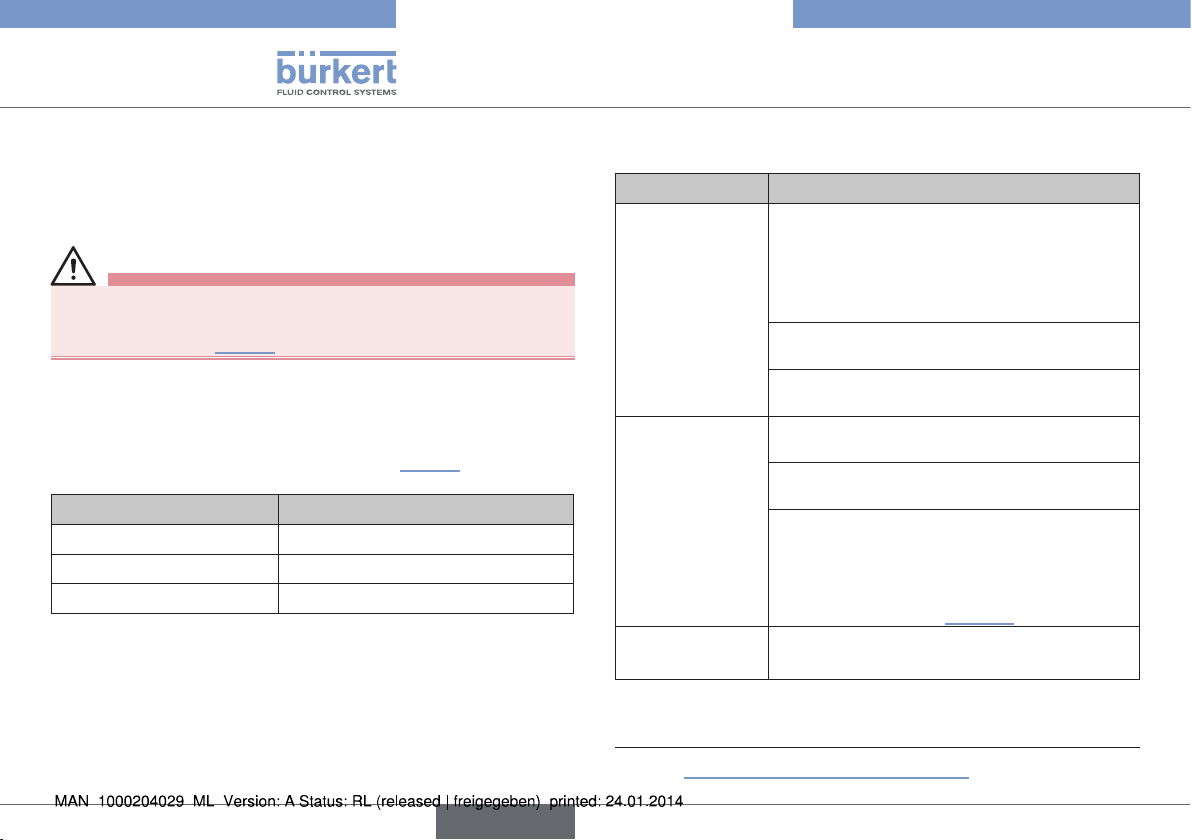
Typ 2036
Störungen
→ Schrauben / Muttern kreuzweise festziehen, bis ein sichtbarer,
gleichmäßiger mechanischer Kontakt zwischen Ventilgehäuse,
Membran und Antrieb gegeben ist.
→ Membranventil zweimal schalten.
WARNUNG!
Verletzungsgefahr durch Mediumsaustritt und Druckentladung.
▶ Darauf achten, dass die Gehäuseschrauben ausreichend ange-
zogen sind (siehe „Tab. 5“).
→ Antrieb in die untere Antriebsposition bringen. (SFA durch Entfernen
des Steuerdrucks, SFB durch Anlegen von Steuerdruck).
→ Ohne Druckbeaufschlagung die Gehäuseschrauben bis zum zuläs-
sigen Anziehdrehmoment anziehen (siehe „Tab. 5“).
Baugröße Anziehdrehmomente [Nm]
RV50 6
RV70 17
RV110 30
Tab. 5: Anziehdrehmomente
13. STÖRUNGEN
Störung Ursache /Beseitigung
Antrieb schaltet
nicht.
Membranventil ist
nicht dicht.
Steuerluftanschluss vertauscht
SFA: Steuerluftanschluss 1 und/oder 3
anschließen
SFB: Steuerluftanschluss 2 und/oder 4
anschließen
Steuerdruck zu gering
Siehe Druckangabe auf dem Typschild.
Mediumsdruck zu hoch
Siehe Druckangabe auf dem Typschild.
Mediumsdruck zu hoch
Siehe Druckangabe auf dem Typschild.
Steuerdruck zu gering
Siehe Druckangabe auf dem Typschild.
Antrieb ist gegenüber dem Ventilgehäuse um
90° gedreht montiert.
→ Führungsbolzen, Kennzeichnungslasche
und Gehäusesitze müssen parallel ausgerichtet sein (siehe „Bild 22“).
Durchflussmenge
verringert.
Tab. 6: Störungen
Membran ausgebeult
→ Membran austauschen.
6)
60
6) siehe „Bild 17: Pneumatischer Anschluss“ .
deutsch
Page 61

Typ 2036
Ersatzteile
14. ERSATZTEILE
WARNUNG
Verletzungsgefahr beim Öffnen des Antriebs.
Der Antrieb enthält eine gespannte Feder. Beim Öffnen des Antriebs
kann es durch die herausspringende Feder zu Verletzungen kommen!
▶ Der Antrieb darf nicht geöffnet werden.
VORSICHT!
Verletzungsgefahr, Sachschäden durch falsche Teile.
Falsches Zubehör und ungeeignete Ersatzteile können Verletzungen
und Schäden am Gerät und dessen Umgebung verursachen.
▶ Nur Originalzubehör sowie Originalersatzteile der Fa. Bürkert
verwenden.
Als Ersatzteil für das Membranventil Typ 2036 ist die Membran
erhältlich.
Wenden Sie sich bei Fragen bitte an Ihre
Bürkert-Vertriebsniederlassung.
14.1. Bestelltabelle
Baugröße Bestellnummern für Membranen
EPDM
Code AD
RV50 236 280 236 281
RV70 236 282 236 283
RV110 236 284 236 285
Tab. 7: Bestelltabelle Membran
Andere Membranqualitäten auf Anfrage.
Advanced PTFE/EPDM
Code EK
deutsch
61
Page 62

15. TRANSPORT, LAGERUNG,
VERPACKUNG
HINWEIS!
Transportschäden.
Unzureichend geschützte Geräte können durch den Transport
beschädigt werden.
▶ Gerät vor Nässe und Schmutz geschützt in einer stoßfesten
Verpackung transportieren.
▶ Eine Über- bzw. Unterschreitung der zulässigen Lagertempera-
tur vermeiden.
▶ Elektrische Schnittstellen der Spule und die pneumatischen
Anschlüsse mit Schutzkappen vor Beschädigungen schützen.
Falsche Lagerung kann Schäden am Gerät verursachen.
▶ Gerät trocken und staubfrei lagern.
▶ Lagertemperatur 0 … +60 °C.
Lagerung mit festgezogenen Gehäuseschrauben kann zu
bleibenden Verformungen der Membran führen.
▶ Gehäuseschrauben bei längerer Einlagerung lockern.
Typ 2036
Transport, Lagerung, Verpackung
Umweltschäden durch von Medien kontaminierte Geräteteile.
▶ Gerät und Verpackung umweltgerecht entsorgen.
▶ Geltende Entsorgungsvorschriften und Umweltbestimmungen
einhalten.
62
deutsch
Page 63

Type 2036
Sommaire
1 À PROPOS DE CE MANUEL ................................................................ 65
1.1 Symboles ...................................................................................65
1.2 Définition du terme / abréviation ..........................................65
2 UTILISATION CONFORME ...................................................................66
2.1 Restrictions ...............................................................................66
3 CONSIGNES DE SÉCURITÉ FONDAMENTALES......................66
3.1 Utilisation dans la zone Ex ........................................................67
3.2 Conditions particulières .........................................................69
4 INDICATIONS GÉNÉRALES .................................................................69
4.1 Adresse......................................................................................69
4.2 Garantie légale .........................................................................69
4.3 Informations sur Internet ........................................................69
5 DESCRIPTION DU PRODUIT ..............................................................70
5.1 Description générale ..............................................................70
5.2 Variantes de l'appareil ............................................................70
5.3 Options ......................................................................................71
5.4 Vidange automatique des vannes ........................................ 71
5.5 Symboles de vanne et diagrammes d'écoulement ..........73
5.6 Identification de la vanne .......................................................74
5.7 Utilisation prévue .....................................................................75
6 STRUCTURE ET MODE DE FONCTIONNEMENT ..................... 76
6.1 Structure ....................................................................................76
6.2 Actionneur .................................................................................76
6.3 Indicateur de position .............................................................77
7 CARACTÉRISTIQUES TECHNIQUES .............................................77
7.1 Conformité ................................................................................77
7.2 Normes ......................................................................................77
7.3 Homologations .........................................................................77
7.4 Plaque signalétique .................................................................77
7.5 Conditions d'exploitation .......................................................78
7.6 Caractéristiques mécaniques ...............................................78
7.7 Données fluidiques .................................................................79
8 MONTAGE ..................................................................................................... 81
8.1 Consignes de sécurité ...........................................................81
8.2 Avant le montage .....................................................................81
8.3 Montage.....................................................................................82
8.4 Raccordement pneumatique ................................................83
9 COMMANDE ÉLECTRIQUE ..................................................................85
10 DÉMONTAGE ............................................................................................... 85
11 MAINTENANCE, NETTOYAGE .............................................................86
11.1 Consignes de sécurité ...........................................................86
11.2 Intervalle d'entretien ................................................................86
11.3 Travaux de maintenance.........................................................86
11.4 Nettoyage ..................................................................................87
12 MAINTENANCE ........................................................................................... 87
12.1 Consignes de sécurité ...........................................................87
12.2 Remplacement de la membrane ..........................................88
français
63
Page 64

13 PANNES .........................................................................................................91
14 PIÈCES DE RECHANGE ........................................................................91
14.1 Tableau de commande ...........................................................92
15 TRANSPORT, STOCKAGE, EMBALLAGE ...................................... 92
Type 2036
64
français
Page 65

Type 2036
À propos de ce manuel
1 À PROPOS DE CE MANUEL
Ce manuel décrit le cycle de vie complet de l'appareil. Conservez ce
manuel de sorte qu'il soit accessible à tout utilisateur et à disposition
de tout nouveau propriétaire.
AVERTISSEMENT !
Ce manuel contient des informations importantes sur la
sécurité.
Le non-respect de ces consignes peut entraîner des situations
dangereuses.
▶ Ce manuel doit être lu et compris.
1.1 Symboles
DANGER !
Met en garde contre un danger imminent.
▶ Le non-respect peut entraîner la mort ou de graves blessures.
AVERTISSEMENT !
Met en garde contre une situation éventuellement
dangereuse.
▶ Risque de blessures graves, voire la mort en cas de non-respect.
ATTENTION !
Met en garde contre un risque possible.
▶ Le non-respect peut entraîner des blessures moyennes ou légères.
REMARQUE !
Met en garde contre des dommages matériels.
▶ L'appareil ou l'installation peut être endommagé(e) en cas de
non-respect.
désigne des informations complémentaires importantes, des
conseils et des recommandations.
renvoie à des informations dans ce manuel ou dans d'autres
documentations.
▶ Identifie une instruction visant à éviter un danger.
→ Identifie une opération que vous devez effectuer.
1.2 Définition du terme / abréviation
Le terme « appareil » utilisé dans ce manuel désigne toujours la
vanne à membrane multi-voies Robolux type 2036.
Le terme « vanne à membrane » utilisé dans ce manuel désigne toujours la vanne à membrane multi-voies Robolux type 2036.
’Abréviation « Ex » utilisé dans ce manuel désigne toujours
«présentant des risques d‘explosion ».
français
65
Page 66

Type 2036
Utilisation conforme
2 UTILISATION CONFORME
L'utilisation non conforme de la vanne à membrane multivoies Robolux 2036 peut présenter des risques pour les personnes, les installations proches et l'environnement.
L'appareil a été conçu pour commander le débit de fluides
liquides.
▶ Lors de l'utilisation, il convient de respecter les données et
conditions d'utilisation et d'exploitation admissibles spécifiées
dans les documents contractuels, ce manuel et sur la plaque
signalétique. Les utilisations prévues sont reprises au chapitre «
5 Description du produit ».
▶ L'appareil peut être utilisé uniquement en association avec les
appareils et composants étrangers recommandés et homologués par Bürkert.
▶ Les conditions pour l'utilisation sûre et parfaite sont un trans-
port, un stockage et une installation dans les règles ainsi qu'une
utilisation et une maintenance parfaites.
▶ Veillez à ce que l'utilisation de l'appareil soit toujours conforme.
2.1 Restrictions
Lors de l'exportation du système/de l'appareil, veuillez respecter les
restrictions éventuelles.
3 CONSIGNES DE SÉCURITÉ
FONDAMENTALES
Ces consignes de sécurité ne tiennent pas compte
• des hasards et des événements pouvant survenir lors du montage,
de l'exploitation et de l'entretien des appareils.
• des prescriptions de sécurité locales que l'exploitant est tenu de
faire respecter entre autres par le personnel chargé du montage.
DANGER !
Risque de blessures dû à la présence de haute pression dans
l‘installation/l‘appareil.
▶ Avant de travailler sur l’installation ou l’appareil, il convient de
couper la pression et de purger des conduites/de les vider.
Risque de choc électrique.
▶ Avant de travailler sur l’installation ou l’appareil, couper la tension
et empêcher toute remise sous tension par inadvertance.
▶ Respecter les réglementations en vigueur pour les appareils élec-
triques en matière de prévention des accidents et de sécurité.
AVERTISSEMENT !
Risque de blessures à l'ouverture de l'actionneur.
L'actionneur contient des ressorts tendus. Il y a risque de blessures à l'ouverture de l'actionneur suite à la détente des ressorts.
▶ L'ouverture de l'actionneur n'est pas autorisée.
66
français
Page 67

Type 2036
Consignes de sécurité fondamentales
ATTENTION !
Risque de brûlures.
La surface de l'appareil peut devenir brûlante en fonctionnement continu.
▶ Ne pas toucher l'appareil à mains nues.
Risque d'écrasement dû aux extrémités de la tige en
mouvement.
▶ Monter le capot transparent.
Situations dangereuses d'ordre général.
Pour prévenir les blessures, respectez ce qui suit :
▶ L'actionnement par inadvertance de l'installation ne doit pas être
possible.
▶ Les travaux d'installation et de maintenance doivent être effectués
uniquement par des techniciens qualifiés et habilités disposant
de l'outillage approprié.
▶ Après une interruption de l'alimentation électrique ou pneumatique,
un redémarrage défini ou contrôlé du processus doit être garanti.
▶ L'appareil doit être utilisé uniquement en parfait état et en res-
pectant ce manuel.
▶ Les règles générales de la technique s'appliquent pour planifier
l'utilisation et utiliser l'appareil.
Pour prévenir les dommages matériels, respectez ce qui suit :
▶ Alimenter les raccords de fluides seulement avec les liquides de
débit énumérés au chapitre « 7 Caractéristiques techniques ».
▶ Ne pas soumettre le corps à des contraintes mécaniques (par
ex. en y déposant des objets sur le corps ou en l'utilisant comme
marche-pied).
▶ Ne pas entreprendre de modifications à l'extérieur des vannes.
Ne pas laquer les pièces du corps ni les vis.
3.1 Utilisation dans la zone Ex
L’abréviation « Ex » : voir chapitre « 1.2 Définition du terme / abréviation »
3.1.1 Consignes de sécurité
En cas d'utilisation en zones Ex (gaz) 1 et 2,
zones (poussière) 21 et 22, s'applique :
L'actionneur de la vanne est approprié comme appareil de catégorie 2
pour zone 1 & 21, équipement non électrique.
français
67
Page 68

Type 2036
Consignes de sécurité fondamentales
DANGER !
Risque d'explosion dû à la charge électrostatique.
Des charges électrostatiques peuvent se produire au niveau de la
membrane de vanne en fonction de la conductibilité du fluide et en
cas d'utilisation de corps en plastique
Pour empêcher les charges électrostatiques dans la fluidique, il convient
de respecter les consignes suivantes (selon IEC 60079-32-1):
▶ (1) Les fluides d’une conductibilité ≤ 100 pS/m doivent être utilisés
uniquement en l’absence de vitesses d’écoulement > 1 m/s ou si
tout fonctionnement à sec de la tuyauterie est exclu grâce à une
surveillance appropriée.
▶ (2) Les fluides d’une conductibilité > 100 pS/m et ≤ 1000 pS/m
doivent être utilisés uniquement s’il s’agit de liquides sans particules, de vapeur d’eau ou de gaz/vapeurs purs ou si les consignes
reprises sous (1) sont respectées.
▶ (3) Les fluides d’une conductibilité > 1000 pS/m ne sont soumis
à aucune limitation
Autres instructions :
▶ L‘utilisateur doit garantir que l‘appareil sera utilisé uniquement dans
la zone 1/21 ou 2/22.
▶ L'unité de commande peut limiter l’utilisation dans une atmos-
phère explosible. Respecter les manuels d'utilisation de l'unité de
commande.
▶ Contrôler l'homologation des produits de nettoyage pour atmos-
phère explosible.
3.1.2 Température du fluide
DANGER !
▶ Un risque supplémentaire d'explosion peut survenir en cas d'uti-
lisation de fluides explosifs
▶ La classe de température T3 / 200°C (poussières) s'applique
lorsque des températures de fluide situées entre 130°C et 150°C
sont utilisées.
Température du fluide max. 130 °C
3.1.3 Marquage Ex
PTB 13 ATEX D103 X
II 2G c IIC T4
II 2D c T135°C
Warning: Not valid when Non-Ex devices added.
Do not open actuator. Spring loaded cover.
Fig. 1 : Marquage Ex
La marquage Ex n'est pas valable si des appareils non Ex
sont ajoutés.
68
français
Page 69

Type 2036
Indications générales
3.2 Conditions particulières
→ Pour assurer la compensation de potentiel, mettre le corps de
vanne à la terre sur la tuyauterie au moyen d‘un raccordement
conducteur.
DANGER !
Risque d'explosion dû à la charge électrostatique.
Il y a risque d'explosion en cas de décharge soudaine d'appareils
ou de personnes chargés d'électricité statique dans la zone explosible (zone Ex).
▶ S'assurer par des mesures appropriées, qu'il ne peut y avoir de
charges électrostatiques dans la zone explosible (voir aussi «
3.1 Utilisation dans la zone Ex »).
▶ Ne nettoyer la surface de l'appareil que par un essuyage léger
avec un chiffon humide ou antistatique.
▶ Mettre à la terre l'actionneur et le corps de vanne.
▶ En cas d'utilisation de corps en plastique, mettre l'actionneur
séparément à la terre.
Plage de température ambiante : 0 °C ≤ Tamb ≤ 60 °C
4 INDICATIONS GÉNÉRALES
4.1 Adresse
Allemagne
Bürkert Fluid Control Systems
Sales Center
Christian-Bürkert-Str. 13-17
D-74653 Ingelfingen
Tél. + 49 (0) 7940 - 10 91 111
Fax + 49 (0) 7940 - 10 91 448
E-mail: info@de.buerkert.com
International
Les adresses se trouvent aux dernières pages du manuel d'utilisation
imprimé.
Elles sont également disponibles sur internet sous :
www.burkert.com
4.2 Garantie légale
La condition pour bénéficier de la garantie légale est l'utilisation
conforme de la vanne à membrane dans le respect des conditions
d'utilisation spécifiées.
4.3 Informations sur Internet
Vous trouverez sur Internet les manuels et fiches techniques relatifs au
type 2036 : www.buerkert.fr
français
69
Page 70

Type 2036
Description du produit
5 DESCRIPTION DU PRODUIT
5.1 Description générale
Les vannes à membrane multi-voies Robolux1) à actionnement pneumatique ou manuel ont été conçues pour contrôler des fluides ultrapurs, stériles, agressifs ou abrasifs. Elles permettent de collecter,
vider ou distribuer de manière optimale des fluides de process
critiques.
Respecter les consignes pour l'utilisation en zone protégée
contre l'explosion. Voir chapitre « 3.1 ».
1) La vanne à membrane multi-voies Robolux sera désignée dans la suite
de ce document de manière abrégée par vanne à membrane.
5.2 Variantes de l'appareil
Les caractéristiques modulaires de la vanne à membrane lui permettent de s'adapter aux conditions d'utilisation les plus diverses.
Trois tailles (RV50, RV70, RV110) sont disponibles en fonction de la
taille de raccordement des vannes à membrane.
Le corps d'actionneur est fabriqué à partir d'un bloc en acier inoxydable. Des corps de vanne en plastique (PVDF ou PP) sont proposés pour certaines conditions d'utilisation.
Des membranes de qualité élevée séparent complètement le fluide
critique de l'actionneur.
Les vannes à membrane pouvant réaliser une multitude de fonctions,
leur configuration est très variée. Selon sa fonction, la vanne peut
disposer de un, deux ou trois actionneurs.
Actionneur à
actionnement
pneumatique
Membrane
Corps de vanne
Fig. 2 : Vanne à membrane, structure et description
70
français
Page 71

Type 2036
Description du produit
5.3 Options
Les options suivantes sont disponibles pour le pilotage des actionneurs
et le retour d'information des différentes positions de commutation.
• Tête de réponse type 8685 disposant de jusqu'à quatre indicateurs de retour de position dans les versions 24 V DC, Interface
ASet EExi.
• Tête de commande type 8686 disposant de jusqu'à deux vannes
pilote et quatre indicateurs de retour de position dans les versions
24 V DC, Interface AS et EExi.
5.4 Vidange automatique des vannes
La vidange automatique s'effectue différemment selon les types
de vanne. Il est très important de connaître les voies de passage
de chaque vanne avant de sélectionner le port / le raccordement
(marqué A, B, C ou D) pour la vidange.
En cas de questions, adressez-vous à votre distributeur
Bürkert ou à notre Sales Center, e-mail : info@de.buerkert.com
Positions de montage pour la vidange :
A
B
3C2S / 4C2S
raccord de vidange
B (D)
Fig. 3 : Vidange automatique - 3C2S / 4C2S
C
A
A
B
3C2S / 4C2S
raccord de vidange
C
B
D
C
B
A
C
C (A)
français
71
Page 72

Type 2036
Description du produit
Positions de montage pour la vidange :
A
B
C
D
4C4S CF
raccord de vidange
D
Fig. 4 : Vidange automatique - 4C4S CF
Positions de montage pour la vidange :
B
D
A
D
C
raccord de vidange
Fig. 5 : Vidange automatique - 4C4S DFP
C
A
4C4S DFP
A (C)
B
A
A
raccord de vidange
D
C
B
D
C
B
4C4S DFP
B (D)
72
français
Page 73

Type 2036
Description du produit
5.5 Symboles de vanne et
diagrammes d'écoulement
3 raccords, 2 sièges
3C2S
Siège
Siège U2Siège
U1
A
U1 U2
C
B
4 raccords, 2 sièges
4C2S
U1
A
U1 U2
4 raccords, 4 sièges
4C4S CF
B
B
Siège U2Siège
L1
A
C
Siège
D
L2
Siège
C
Siège
vue du dessus vue du dessous
A
U1
D
U2
D
L2
B
A
U1
C
L1
B
D
U2
C
Fig. 6 : Symboles de vanne et diagrammes d'écoulement - 3C2S
/ 4C2S
français
Fig. 7 : Symboles de vanne et diagrammes d'écoulement - 4C4S
CF
73
Page 74

Type 2036
Description du produit
A
Siège
U1
4 raccords, 4 sièges
4C4S DFP
vue du dessus vue du dessous
D
C C
Siège U2Siège
B
L2
A
U1
L1
D
C
B
D
B
L1
U2
5.6 Identification de la vanne
Plaque signalétique
Marquage Ex et
avertissements
Identification de
l'orientation de
l'actionneur
Identification des raccords de conduite
Siège
L2
Inscription du corps de vanne
Bürkert logo de l'entreprise, Diamètre nominal et
dimensions de raccord matériau, charge, ordre de
fabrication et n° de série
Fig. 9 : Identification de la vanne
5.6.1 Marquage de la zone explosible et
avertissements
Voir chapitre « 3.1 Utilisation dans la zone Ex ».
Fig. 8 : Symboles de vanne et diagrammes d'écoulement - 4C4S
DFP
74
français
Page 75

Type 2036
Description du produit
5.6.2 Plaque signalétique
Logo de l'entreprise
Numéro
d'identification
Dimensions de raccordement
Date de construction
Fig. 10 : Plaque signalétique
Type - Taille - Forme de
construction - Matériau
de la membrane
Actionneur 1 - Actionneur 2
- Pression de pilotage
Pression max. du fluide
- Température du fluide
5.6.3 Identification des raccords de
conduite
Tous les raccords de conduite sont dotés de lettres, correspondant
aux diagrammes d'écoulement (voir chapitre « 5.5 Symboles de
vanne et diagrammes d'écoulement »).
5.6.4 Identification de l'orientation de
l'actionneur
L'actionneur est doté d'un marquage dans
la zone de raccordement A pour faciliter le
montage correct des paliers.
5.7 Utilisation prévue
La vanne à membrane est conçue pour l'utilisation avec des fluides
encrassés et agressifs n'attaquant pas les matériaux du corps et du joint.
Respectez la plage de pression maximale indiquée sur la
plaque signalétique.
• Fluides très purs, stériles, agressifs ou abrasifs.
• Fluides à viscosité élevée.
Respecter les consignes pour l'utilisation en zone protégée
contre l'explosion. Voir chapitre « 3.1 ».
5.7.1 Domaines d'application
Par ex. construction d'installations
industrie agro-alimentaire
stations de remplissage
technique des procédés chimiques
pharmacie
Fig. 11 : Identification de l'orientation de l'actionneur
français
75
Page 76

Type 2036
1(P)
2(A)
1(P)
2(B)
Structure et mode de fonctionnement
6 STRUCTURE ET MODE DE
FONCTIONNEMENT
6.1 Structure
La vanne à membrane est composée d'un d'actionneur par piston à
actionnement pneumatique, d'une membrane et d'un corps de vanne
multi-voies.
Capot transparent avec
indicateur de position
Capot de l'actionneur
Raccord d'air de pilotage 4
Raccord d'air de pilotage 2
Raccord d'air de pilotage 3
Raccord d'air de pilotage 1
Corps de l'actionneur
Vis du corps
Broche guide
Membrane
Corps de vanne
6.2 Actionneur
L'actionneur possède deux chambres d'actionneur, qui peuvent être
pilotées indépendamment l'une de l'autre et qui agissent respectivement sur un siège du corps (actionneur double). Dans le cas d'un
actionneur simple, la vanne est équipée d'une seule chambre avec
des pièces internes de fonctionnement.
L'effet de ressort (CFA, NF) ou la pression de pilotage pneumatique
(CFB, NO) génère la force de fermeture sur l'actionneur.
La force est transmise respectivement par une tige reliée au
piston d'actionneur, à la pièce de pression correspondante et à la
membrane.
6.2.1 Fonctions (CF)
Fonction A, NF (CFA)
En position de repos, fermée par
ressort
Fonction B, NO (CFB)
En position de repos, ouverte par
ressort
Fig. 12 : Vanne à membrane commandée par piston, structure et
76
description
français
Page 77

Type 2036
Caractéristiques techniques
6.3 Indicateur de position
La position des deux chambres d'actionneur est signalée par des
indicateurs de position. Deux positions sont possibles :
• Débordement court de l'indicateur de position → vanne fermée.
• Débordement long de l'indicateur de position → vanne ouverte.
ATTENTION !
Risque d'écrasement dû aux extrémités de la tige en
mouvement.
▶ Monter le capot transparent.
Débordement long
Débordement court
Capot transparent
retiré
Fig. 13 : Indicateur de position
7 CARACTÉRISTIQUES
TECHNIQUES
7.1 Conformité
La vanne à membrane de type 2036 est conforme aux directives CE
conformément à la déclaration de conformité CE.
7.2 Normes
Les normes utilisées, avec lesquelles la conformité avec les directives
CE sont prouvées, figurent dans l'attestation CE de type et/ou la
déclaration de conformité CE.
7.3 Homologations
L'appareil est conçu pour être utilisé conformément à la directive
ATEX 94/9/CE, catégorie 2G/D, zones 1 et 21.
Respecter les consignes pour l'utilisation en zone protégée
contre l'explosion. Voir chapitre « 3.1 ».
7.4 Plaque signalétique
Voir chapitre « 5.6 Identification de la vanne ».
français
77
Page 78

Type 2036
Caractéristiques techniques
7.5 Conditions d'exploitation
Respectez la plage de pression admissible indiquée sur la
plaque signalétique de l'appareil.
2)
Température ambiante -10 ... +60 °C
températures plus élevées sur demande
Humidité relative de l'air max. 80 % (sans condensation)
7.6 Caractéristiques mécaniques
Dimensions voir fiche technique
Matériaux
Matériau du corps Acier inoxydable : 1.4435/316L
(autres matériaux sur demande)
Membrane EPDM, Advanced PTFE/EPDM, FKM,
silicone
Actionneur
corps Acier inoxydable coulée de précision
1.4308
Pièces de pression PPS (Polyphenylensulfid) et V2A
2) La température ambiante maximale est de +55 °C en cas d'utilisation
d'une commande ou d'une vanne pilote.
Raccordements
Raccords de conduite Raccord à souder
DIN EN ISO 1127 / ISO 4200 /
DIN 11866 série 2
DIN 11850 série 2 /
DIN 11866 série A
ASME BPE / DIN 11866 série C
Clamp
DIN 32676 série A (DIN conduit)
DIN 32676 série B (ISO conduit)
ASME BPE
(autres raccords à sur demande)
Raccord d'air de pilotage G1/8
Qualité de surface intérieure Ra 0,5 µm passivé
extérieure Ra 3,2 µm par enlè-
vement de copeaux
option électropoli
(autres qualités de surface sur demande)
Position de montage au choix, de préférence raccord B vers
le bas ; pour la vidange automatique
voir chapitre « 5.4 Vidange automatique des vannes »
La durée de vie de l'appareil dépend fortement des conditions d'utilisation. La durée de vie de la membrane dépend fortement des conditions de service, comme par exemple le fluide, les températures, la
fréquence de commutation, la pression etc. et Peut diverger fortement
dans certains cas particuliers.
78
français
Page 79

Type 2036
Caractéristiques techniques
7.6.1 Membrane
La membrane assure l'étanchéité de la vanne. Elle doit être choisie
avec soin. La sélection du matériau doit être appropriée au fluide de
process, à la température et aux conditions de service (par exemple à
la pression de service, à la fréquence de commutation etc.).
Le tableau suivant indique les matériaux standards.
Conformité à FDA CFR 21 §177.2600 ou §177.1550 et certificat
USP VI voir « Tab. 1 : Matériaux de la membrane ».
Matériau
de la
membrane
EPDM AD éthylène-pro-
Advanced
PTFE /
EPDM
FKM FL caoutchouc
silicone SK caoutchouc de
Tab. 1 : Matériaux de la membrane
Code Description du
matériau
pylène-caoutchouc vulcanisé
au péroxyde
EK Advanced
PTFE
vulcanisé sur
EPDM
synthétique
fluorocarboné
silicone stabilisé au platine
Application FDA USP
VI
produits
x x
chimiques oxydants, vapeur et
eau chaude
les principaux
x x
produits
chimiques et
acides
acides et huiles
x
minérales
huiles
x x
aliphatiques
7.7 Données fluidiques
Fluides
Fluides de débit ultra-pur, stérile, agressif, (voir éga-
lement chapitre « 7.6.1 Membrane »)
Pression du fluide voir chapitre « 7.7.1 »
Température du fluide
acier inoxydable/EPDM +5 à +130 °C
(max. +143 °C pour 60 min.)
acier inoxydable/
Advanced EPDM +5 à +90 °C
(pas de stérilisation à la vapeur)
acier inoxydable/FKM +5 à +130 °C
(chaleur sèche jusqu‘à +143 °C max)
acier inoxydable/silicone +5 à +130 °C
(chaleur sèche jusqu‘à +143 °C max)
Respecter les consignes pour l'utilisation en zone protégée
contre l'explosion. Voir chapitre « 3.1 ».
Fluide de pilotage Gaz neutres, séchés à l'air (min. 10 k
sou la température de service min.), de
préférence non huilé
Pression de pilotage
3) Indication de pression [bar] : Surpression par rapport à la pression
atmosphérique
3)
6 ... 10 bars (RV50, RV70)
6 ... 7 bars (RV110)
à partir de 4,2 bars (avec pression du
fluide réduite) sur demande
français
79
Page 80

Type 2036
Caractéristiques techniques
7.7.1 Plages de pression
Pression de pilotage et pression de service pour CFA, NF
Valeurs pour corps en acier inoxydable
Pression
Taille
RV50
RV70
RV110
Version de
l'actionneur
D11
D1x; Dx1
D55 4,2 ... 10
D11
D1x; Dx1
D55 4,2 ... 10
D11
D1x; Dx1
D55 4,2 ... 7
de
4)
pilotage
[bar]
6 ... 10
6 ... 10
6 ... 7
Critère
d'essai
5)
statique 7,5 7,5
dynamique 6,5 5,5
statique 5,0 3,5
dynamique 4,0 2,5
statique 8,0 8,0
dynamique 6,0 6,0
statique 5,5 6,0
dynamique 3,5 4,0
statique 7,0 7,5
dynamique 5,0 5,5
statique 5,0 5,0
dynamique 3,0 3,0
Tab. 2 : Pression de pilotage et pression de service
4) Voir plaque signalétique.
5) Indication de pression [bar] : Surpression par rapport à la pression
atmosphérique
Pression de
service maxi [bar]
EPDM,
FKM,
silicone
Advanced
PTFE/
EPDM
Remarques
Étanchéité statique :
la vanne est fermée (la membrane repose contre le siège du corps).
La pression est présente d'un côté du siège du corps. À la pression
indiquée, aucune fuite ne survient au-dessus du siège du corps.
5)
Étanchéité dynamique :
la vanne s'ouvre et est traversée par le fluide. Le côté écoulement
n'est étranglé par les composants suivants que de manière réduite.
La pression est présente des deux côtés siège du corps. La vanne
se ferme (CFA, NF par la force du ressort ; CFB, NO par la pression
de pilotage). À la pression indiquée, la vanne se ferme de manière
étanche au-dessus du siège de corps.
Étanchéité statique :
Étanchéité dynamique :
Fig. 14 : Étanchéité statique et dynamique
80
français
Page 81

Type 2036
Montage
Pression de pilotage et pression de service pour CFB, NO
Les diagrammes suivants représentent la pression de pilotage
minimale nécessaire en fonction de la pression de fluide pour la
fonction B.
Pression de pilotage admissible : 2 ... 7 bar.
Sélectionner la pression de pilotage aussi faible que possible pour ménager la membrane.
RV50/RV110
statique
RV70
8
7
6
5
4
3
Pression du fluide [bar]
2
1
0
0 1 2 3 4 5 6 7
Plage pour vannes avec une commande
statique
Pression de pilotage
[bar]
RV70
dynamique
RV50/RV110
dynamique
8 MONTAGE
8.1 Consignes de sécurité
DANGER !
Risque de blessures dû à la présence de haute pression dans
l‘installation/l‘appareil.
▶ Avant de travailler sur l’installation ou l’appareil, il convient de
couper la pression et de purger des conduites/de les vider.
AVERTISSEMENT !
Risque de blessures dû à un montage non conforme.
▶ Le montage doit être effectué uniquement par un personnel
qualifié et habilité disposant de l'outillage approprié.
Risque de blessures dû à la mise en marche involontaire de
l'installation et au redémarrage non contrôlé.
▶ Empêchez tout actionnement involontaire de l'installation.
▶ Garantissez un redémarrage contrôlé après le montage.
8.2 Avant le montage
→ Avant de raccorder la vanne, veillez à ce que les tuyauteries
soient correctement alignées.
→ Respectez le sens du débit.
Fig. 15 : Pression de pilotage en fonction de la pression de fluide
français
81
Page 82

8.2.1 Position de montage
• La position de montage de la vanne à membrane commandée par
piston est au choix, de préférence raccord B vers le bas.
• Montage pour permettre au corps de se vider automatiquement :
voir chapitre « 5.4 Vidange automatique des vannes »
Type 2036
Montage
8.2.2 Travaux préparatoires
→ Nettoyez les tuyauteries (matériau d'étanchéité, copeaux de
métal, etc.).
→ Soutenez et alignez les tuyauteries.
Appareils avec corps à souder
REMARQUE !
Endommagement de la membrane et/ou de l'actionneur.
▶ Démonter l'actionneur et la membrane avant de souder le corps.
Démonter l'actionneur du corps de vanne :
→ Mettre l'actionneur dans la position supérieure (CFA, NF par
création de la pression de pilotage, CFB, NO par élimination de la
pression de pilotage).
→ Marquer la position de l'actionneur par rapport au corps de
vanne.
→ Desserrer les quatre vis du corps qui relient le corps de vanne à
l'actionneur. Retirer l'actionneur et la membrane.
82
Actionneur
Broche guide
Vis du corps
Membrane
Corps de vanne
Fig. 16 : Montage
8.3 Montage
AVERTISSEMENT !
Risque de blessures dû à un montage non conforme.
Le non respect des couples de serrage est dangereux en raison de
la fuite possible du fluide et de la décharge possible de pression.
▶ Respectez le couple de serrage (voir « Tab. 3 »).
français
Page 83

Type 2036
Montage
8.3.1 Monter le corps
Corps à souder
→ Souder le corps de vanne dans le système de tuyauterie.
Autres versions de corps
→ Relier le corps à la tuyauterie.
8.3.2 Monter l'actionneur (corps à souder)
→ Mettre l'actionneur dans la position supérieure (CFA, NF par
création de la pression de pilotage, CFB, NO par élimination de la
pression de pilotage).
→ Placer correctement l'unité actionneur / membrane sur le corps (de
façon à ce que les marquages effectués auparavant s'alignent). Sur
la RV110, les quatre douilles d'écartement doivent pénétrer dans
les forages de corps prévus (voir « Fig. 20 : Démontage / montage
de la membrane » à la page 89).
→ Serrer à fond en croix les vis / écrous du corps, jusqu'à ce qu'un
contact mécanique uniforme visible se forme entre le corps de
vanne, la membrane et l'actionneur.
→ Commuter plusieurs fois la vanne à membrane.
AVERTISSEMENT !
Risque de blessures dû à la sortie de fluide et à la décharge
de pression.
▶ Serrer suffisamment à fond les vis du corps.
→ Mettre l'actionneur dans la position inférieure (CFA, NF par éli-
mination de la pression de pilotage, CFB, NO par création de la
pression de pilotage).
→ Sans alimentation en pression de pilotage, serrer les vis du
corps jusqu'au couple de serrage autorisé (voir « Tab. 3 »).
Taille Couple de serrage [Nm]
RV50 6
RV70 17
RV110 30
Tab. 3 : Couple de serrage
8.4 Raccordement pneumatique
DANGER !
Risque de blessures dû à la présence de haute pression dans
l‘installation/l‘appareil.
▶ Avant de travailler sur l’installation ou l’appareil, il convient de
couper la pression et de purger des conduites/de les vider.
français
83
Page 84

Type 2036
Montage
AVERTISSEMENT !
Risque de blessures dû aux tuyaux flexibles de raccordement
non appropriés.
Les tuyaux flexibles ne résistant pas aux plages de pression et de
température peuvent entraîner des situations dangereuses.
▶ Utilisez uniquement des tuyaux flexibles homologués pour les
plages de pression et de température indiquées.
▶ Respectez les indications figurant sur la fiche technique du
fabricant de tuyaux flexibles.
8.4.1 Raccordement du fluide de pilotage
Pour respecter le degré de protection IP65 / IP67 sur le
raccord d'air de pilotage superflu (sur CFA, NF et CFB, NO),
monter une conduite d'évacuation d'air dans la zone sèche.
Affectation des raccords d'air de pilotage, voir le plan d'installation et de
mesures fourni avec la vanne. Comparer également avec les indications
au chapitre « 6 Structure et mode de fonctionnement ».
Il est recommandé d'utiliser des tuyaux flexibles d'air de pilotage de
la taille 6/4 mm. Pour des longueurs de conduites plus importantes,
adapter en conséquence les sections transversales des flexibles.
Dans un environnement agressif et dans des situations où
de l'humidité peut pénétrer dans l'actionneur par le raccord
d'évacuation d'air ou le silencieux, l'air d'évacuation doit être
cerné et dévié dans un environnement non critique.
Fonction A:
→ Raccorder le fluide de pilotage au raccord d’air de pilotage 1 et/
ou 3 (voir « Fig. 17 »).
Fonction B:
→ Raccorder le fluide de pilotage au raccord d’air de pilotage 2 et
4 (voir « Fig. 17 »).
Silencieux
→ Raccorder le silencieux dans le raccord de purge d’air libre (voir
« Fig. 17 »).
Actionneur 1
(à gauche)
Raccords d'air
de pilotage
2 (P2)
Raccords d'air
de pilotage
1 (P1)
Actionneur 2
(à droite)
Raccords d'air
de pilotage
4 (P4)
Raccords d'air
de pilotage
3 (P3)
84
Fig. 17 : Raccordement pneumatique
français
Page 85

Type 2036
Commande électrique
Version de
l'actionneur
D11, D55
CFA/CFA
D12
CFA/CFB
D21
CFB/CFA
D22
CFB/CFB
Actionneur 1 Actionneur 2
CF Raccordement CF Raccordement
Air de
pilotage
A
P2: purge d’air
Air de
pilotage
A
P2: purge d’air
Air de
pilotage
B
P1: purge d’air
Air de
pilotage
B
P1: purge d’air
P1
P1
P2
P2
Air de
pilotage
A
P4: purge d’air
Air de
pilotage
B
P3: purge d’air
Air de
pilotage
A
P4: purge d’air
Air de
pilotage
B
P3: purge d’air
Tab. 4 : Raccordement pneumatique pour les versions de
l'actionneur
CFA, NF : Vanne normalement fermée par action du ressort
CFB, NO : Vanne Normalement ouverte par action du ressort
Chiffres
d’identification
Actionneur 1
Chiffres
d’identification
Actionneur 2
Fig. 18 : Film du couvercle
P3
P4
P3
P4
9 COMMANDE ÉLECTRIQUE
Le raccordement électrique de la vanne pilote / de la commande est décrit dans le manuel d'utilisation de la vanne
pilote / de la commande.
Respecter les consignes pour l'utilisation en zone protégée
contre l'explosion. Voir chapitre « 3.1 ».
10 DÉMONTAGE
DANGER !
Risque de blessures dû à la sortie de fluide et à la décharge
de pression.
Le démontage d'un appareil sous pression est dangereux du fait
de la décharge de pression ou de la sortie de fluide soudaines.
▶ Avant le démontage, couper la pression et purger l'air des
conduites.
Si la vanne doit être réutilisée après le démontage, il est
nécessaire de retirer l'actionneur avant le démontage lors
des travaux de soudure. Pour cela, respecter les consignes
de montage.
Procédure à suivre :
→ Desserrer le raccordement pneumatique.
→ Démonter l'appareil.
français
85
Page 86

Type 2036
Maintenance, nettoyage
11 MAINTENANCE, NETTOYAGE
11.1 Consignes de sécurité
DANGER !
Risque de blessures dû à la présence de haute pression dans
l‘installation/l‘appareil.
▶ Avant de travailler sur l’installation ou l’appareil, il convient de
couper la pression et de purger des conduites/de les vider.
Risque de choc électrique.
▶ Avant de travailler sur l’installation ou l’appareil, couper la tension
et empêcher toute remise sous tension par inadvertance.
▶ Respecter les réglementations en vigueur pour les appareils élec-
triques en matière de prévention des accidents et de sécurité.
AVERTISSEMENT !
Risque de blessures dû à des travaux d'entretien non
conformes.
▶ Le montage doit être effectué uniquement par un personnel
qualifié et habilité disposant de l'outillage approprié.
Risque de blessures dû à la mise en marche involontaire de
l'installation et au redémarrage non contrôlé.
▶ Empêchez tout actionnement involontaire de l'installation.
▶ Garantissez un redémarrage contrôlé après l'entretien.
11.2 Intervalle d'entretien
Vérifiez régulièrement le montage, l'installation et le fonctionnement
corrects des vannes à membrane. Tenez compte des facteurs suivants
pour déterminer les intervalles de contrôle :
• Conditions de service (degré de sollicitation, mauvaise utilisation),
• Indications du fabricant figurant dans la documentation technique
(p. ex. durée de vie mécanique),
• Modifications importantes du système.
11.3 Travaux de maintenance
Ne pas réparer soi-même l'appareil, mais le remplacer par
un appareil identique. Seules les réparations effectuées par
le fabricant sont autorisées.
11.3.1 Actionneur
À condition de respecter les consignes de ce manuel d'utilisation,
l'actionneur de la vanne à membrane ne nécessite aucun entretien.
11.3.2 Pièces d'usure de la vanne à
membrane
La membrane est soumise à une usure naturelle.
→ En cas de pertes d'étanchéité, remplacer la membrane
(voir chapitre « 12 Maintenance »).
86
français
Page 87

Type 2036
Maintenance
Une membrane déformée peut entraîner une réduction du
débit.
Le remplacement des pièces d'usure est décrit au chapitre
« 12 Maintenance ».
11.4 Nettoyage
REMARQUE !
Évitez les dommages dus aux produits de nettoyage.
▶ Vérifiez la compatibilité des produits avec les matériaux du
corps avant d'effectuer le nettoyage.
Respecter les consignes pour l'utilisation en zone protégée
contre l'explosion. Voir chapitre « 3.1 ».
Actionneur
Nettoyer la surface de l'actionneur en l'essuyant avec un chiffon
humide. Utiliser seulement des produits de nettoyage qui n'attaquent
pas la surface de l'actionneur.
Corps / membrane
Les corps sont aptes au nettoyage en place (CIP). Nettoyer les
vannes avec des produits de nettoyage qui n'attaquent pas le
matériau du corps et de la membrane. Éviter les produits de nettoyage avec un pH élevé.
12 MAINTENANCE
12.1 Consignes de sécurité
DANGER !
Risque de blessures dû à la présence de haute pression dans
l‘installation/l‘appareil.
▶ Avant de travailler sur l’installation ou l’appareil, il convient de
couper la pression et de purger des conduites/de les vider.
Risque de choc électrique.
▶ Avant de travailler sur l’installation ou l’appareil, couper la tension
et empêcher toute remise sous tension par inadvertance.
▶ Respecter les réglementations en vigueur pour les appareils élec-
triques en matière de prévention des accidents et de sécurité.
AVERTISSEMENT !
Risque de blessures dû à une maintenance non conforme.
▶ Le montage doit être effectué uniquement par un personnel
qualifié et habilité disposant de l'outillage approprié.
▶ Les couples de serrage doivent être respectés.
▶ Après les travaux, contrôlez l'étanchéité et le fonctionnement de
la vanne.
Risque de blessures dû à la mise en marche involontaire de
l'installation et au redémarrage non contrôlé.
▶ Empêchez tout actionnement involontaire de l'installation.
▶ Garantissez un redémarrage contrôlé après l'entretien.
français
87
Page 88

12.2 Remplacement de la membrane
Pièce de rechange nécessaire
• Membrane
12.2.1 Démontage de l'actionneur et de la
membrane
→ Mettre l'actionneur dans la position supérieure (CFA, NF par
création de la pression de pilotage, CFB, NO par élimination de la
pression de pilotage).
→ Marquer la position de l'actionneur par rapport au corps de
vanne.
→ Desserrer les quatre vis / écrous du corps, qui relient le corps de
vanne à l'actionneur. Retirer le corps de vanne.
→ Mettre l'actionneur dans la position inférieure (CFA, NF par éli-
mination de la pression de pilotage, CFB, NO par création de la
pression de pilotage).
→ Dévisser la broche guide jusqu'en butée.
Type 2036
Maintenance
Actionneur
Broche guide
Vis du corps
Membrane
Corps de vanne
Broche guide
88
Fig. 19 : Maintenance
français
Page 89

Type 2036
Maintenance
2
Membrane
Pièces de
pression
Douilles
d'écartement
Fig. 20 : Démontage / montage de la membrane
12.2.2 Montage de l'actionneur et de la
1
Risque de blessures dû aux pièces en mouvement dans l’appareil.
▶ Tenir les membres et objets éloignés des ouvertures de l'actionneur
membrane
AVERTISSEMENT !
lors de la création ou de la suppression de la pression de pilotage
au niveau de l'actionneur.
→ Mettre l'actionneur dans la position inférieure (CFA, NF par éli-
mination de la pression de pilotage, CFB, NO par création de la
pression de pilotage).
→ Introduire la membrane dans le guidage des pièces de pression.
S'assurer que les quatre douilles d'écartement sont montées
(voir « Fig. 20 »).
→ Insérer les pièces de pression dans l'actionneur. Lors de cette
opération, veiller à ce que les tiges d'actionneur s'insèrent complètement dans les cavités correspondantes des pièces de pression
(voir « Fig. 21 »).
→ Tourner à 30° env. la membrane et les pièces de pression.
2
30° env.
Pièces de
pression
→ Tourner à 30° la membrane et les pièces de pression et sortir
celles-ci (pas 1).
→ Sortir la membrane latéralement des pièces de pression (pas 2).
français
1
Tige de
l'actionneur
Fig. 21 : Montage les pièces de pression
89
Page 90

Type 2036
Maintenance
REMARQUE !
Endommagement de la membrane.
▶ Tourner la membrane et les pièces de pression au maximum jusqu'à
ce que les orifices des vis de actionneur et de la membrane soient
au même niveau.
→ Visser la broche guide jusqu'en butée (« Fig. 19 »).
→ Mettre l'actionneur dans la position supérieure (CFA, NF par
création de la pression de pilotage, CFB, NO par élimination de la
pression de pilotage).
Broche guide
Languette d'identification
Membrane
Siège du corps
Fig. 22 : Monter l'actionneur
→ Placer correctement l'unité actionneur / membrane sur le corps (de
façon à ce que les marquages effectués auparavant s'alignent).
ou que la broche guide, la languette d'identification et les sièges
du corps soient orientés de manière parallèle). Sur la RV110, les
quatre douilles d'écartement doivent pénétrer dans les forages de
corps prévus.
→ Serrer à fond en croix les vis / écrous du corps, jusqu'à ce qu'un
contact mécanique uniforme visible se forme entre le corps de
vanne, la membrane et l'actionneur.
→ Commuter plusieurs fois la vanne à membrane.
AVERTISSEMENT !
Risque de blessures dû à la sortie de fluide et à la décharge
de pression.
▶ Serrer suffisamment à fond les vis du corps.
→ Mettre l'actionneur dans la position inférieure (CFA, NF par éli-
mination de la pression de pilotage, CFB, NO par création de la
pression de pilotage).
→ Sans alimentation en pression de pilotage, serrer les vis du corps
jusqu'au couple de serrage autorisé (voir « Tab. 5 »).
Taille Couple de serrage [Nm]
RV50 6
RV70 17
RV110 30
Tab. 5 : Couple de serrage
90
français
Page 91

Type 2036
Pannes
13 PANNES
Panne Cause/Dépannage
L'actionneur
ne commute
pas.
La vanne n'est
pas étanche.
Raccord d'air de pilotage inversé
CFA,
NF :
CFB,
NO :
Pression de pilotage trop faible.
Voir pression indiquée sur la plaque signalétique.
Pression du fluide trop élevée.
Voir pression indiquée sur la plaque signalétique.
Pression du fluide trop élevée.
Voir pression indiquée sur la plaque signalétique.
Pression de pilotage trop faible.
Voir pression indiquée sur la plaque signalétique.
L'actionneur est monté en étant tourné à 90° par
rapport au corps de vanne.
Raccorder le raccord d’air de pilotage 1
et/ou 3
Raccorder le raccord d’air de pilotage 2
et/ou 4
→ La broche guide, la languette d'identification
et les sièges du corps doivent être orientés
de manière parallèle. (voir « Fig. 22 »).
Le débit
diminue.
Tab. 6 : Pannes
La membrane est déformée.
→ Remplacer la membrane.
14 PIÈCES DE RECHANGE
AVERTISSEMENT
6)
.
Risque de blessures à l'ouverture de l'actionneur.
L'actionneur contient un ressort tendu. Il y a risque de blessures à
l'ouverture du corps de l'actionneur suite à la détente du ressort.
▶ L'ouverture de l'actionneur n'est pas autorisée.
ATTENTION !
Risque de blessures, de dommages matériels dus à de mauvaises pièces.
De mauvais accessoires ou des pièces de rechange inadaptées
peuvent provoquer des blessures et endommager l'appareil ou son
environnement.
▶ Utiliser uniquement des accessoires et des pièces de rechange
d'origine de la société Bürkert.
La membrane est disponible en tant que pièce de rechange pour la
vanne à membrane type 2036.
Si vous avez des questions, contactez votre distributeur
Bürkert.
6) voir « Fig. 17 : Raccordement pneumatique ».
français
91
Page 92

Type 2036
Transport, stockage, emballage
14.1 Tableau de commande
Taille Références de commande des membranes
EPDM
Code AD
RV50 236 280 236 281
RV70 236 282 236 283
RV110 236 284 236 285
Tab. 7 : Références de commande des membranes
Autres membranes sur demande.
Advanced PTFE/EPDM
Code EK
15 TRANSPORT, STOCKAGE,
EMBALLAGE
REMARQUE !
Dommages dus au transport.
Les appareils insuffisamment protégés peuvent être endommagés
pendant le transport.
▶ Transportez l'appareil à l'abri de l'humidité et des impuretés et
dans un emballage résistant aux chocs.
▶ Évitez le dépassement vers le haut ou le bas de la température
de stockage admissible.
▶ Protégez les raccords pneumatiques des dommages en utilisant
des capuchons de protection.
Un mauvais stockage peut endommager l'appareil.
▶ Stockez l'appareil au sec et à l'abri des poussières.
▶ Température de stockage : 0 à +60 °C.
Le stockage avec les vis du corps serrées à fond peut
entraîner des déformations définitives de la membrane.
▶ Desserrer les vis du corps en prévision d'un stockage de longue
durée.
Dommages sur l'environnement causés par des pièces d'appareil contaminées par des fluides.
▶ Éliminer l'appareil et l'emballage dans le respect de
l'environnement.
▶ Respecter les prescriptions en matière d'élimination des
déchets et de protection de l'environnement en vigueur.
92
français
Page 93

Page 94

www.burkert.com
 Loading...