

Page 1
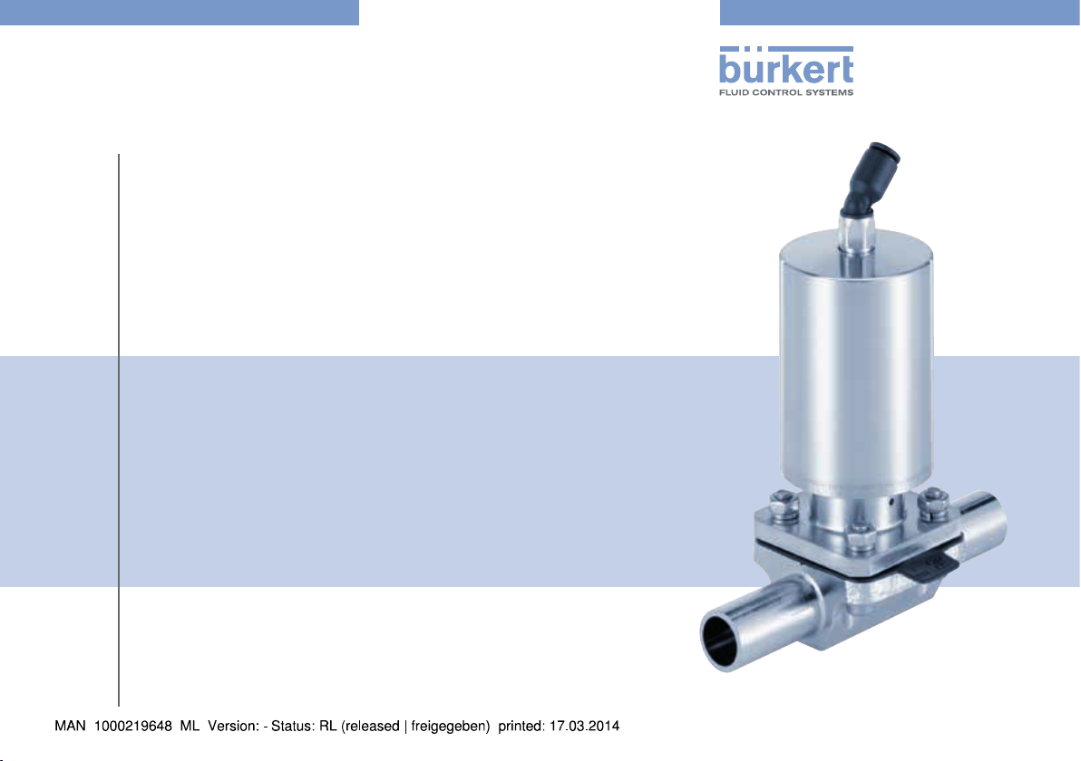
Type 2031
INOX
2/2-way Diaphragm valve
2/2-Wege Membranventil
Vanne à membrane 2/2 voies
Quickstart
English Deutsch Français
Page 2
We reserve the right to make technical changes without notice.
Technische Änderungen vorbehalten.
Sous resérve de modification techniques.
© 2014 Bürkert Werke GmbH
Operating Instructions 1403/00_EU-ML_00810366 / Original DE
Page 3
Type 2031 INOX
Quickstart
Contents
1 QUICKSTART ..................................................................................................3
2 CONTACT ADDRESSES ...........................................................................3
3 INTENDED USE .............................................................................................4
4 BASIC SAFETY INSTRUCTIONS ..........................................................4
5 TECHNICAL DATA ........................................................................................5
6 INSTALLATION ...............................................................................................7
7 START-UP .........................................................................................................9
8 MAINTENANCE, CLEANING ...................................................................9
9 TRANSPORTATION, STORAGE, DISPOSAL ................................ 10
1 QUICKSTART
The quickstart comprises important information.
▶ Carefully read the quickstart and observe any safety information.
▶ The quickstart must be available to every user.
▶ The liability and warranty for type 2031 INOX do not apply if the quick-
start are not observed.
The quickstart illustrates the installation and commissioning of the
equipment with examples. A detailed description of the device can be
found in the operating instructions in the internet at: www.burkert.com
1.1 Definition of term
The term “device” used in these instructions always stands for the
diaphragm valve Type 2031 INOX.
2 CONTACT ADDRESSES
Bürkert Fluid Control Systems / Sales Center
Christian-Bürkert-Str. 13-17
D-74653 Ingelfingen
Tel. + 49 (0) 7940 - 10 91 111
Fax + 49 (0) 7940 - 10 91 448
E-mail: info@de.buerkert.com
International
Contact addresses can be found in the internet at: www.burkert.com
If you have any queries, please contact your Bürkert sales
office.
english
3
Page 4
Type 2031 INOX
Basic safety instructions
2.1 Symbols
Warning to prevent death or serious injuries:
DANGER!
Warns of an immediate danger!
WARNING!
Warns of a potentially dangerous situation!
Warning to prevent moderate or minor injuries:
CAUTION!
Warns of a possible danger!
NOTE!
Warns of material damage!
Important tips and recommendations.
→ designates a procedure which you must carry out.
3 INTENDED USE
Diaphragm valve Type 2031 INOX is designed to control the flow-rate
of liquid and gaseous media.
• Observe the permitted application conditions for using the equipment.
• Operate only when in perfect condition and pay attention to correct
storage, transportation, installation and operation.
4 BASIC SAFETY INSTRUCTIONS
Danger – high pressure!
▶ Before dismounting the lines and valves, turn off the pressure and
vent the lines.
Risk of electric shock!
▶ Before reaching into the device, switch off the power supply and
secure to prevent reactivation!
▶ Observe applicable accident prevention and safety regulations
for electrical equipment!
Risk of crushing from moving pneumatic connection!
▶ When opening and closing the device, do not touch the moving
pneumatic connection.
▶ Do not reach into the area immediately above and below the
control air connection.
Risk of burns/risk of fire if used during long-term operation
through hot device surface!
▶ Do not touch the device with bare hands.
▶ Keep the device away from highly flammable substances and
media.
4
english
Page 5
Type 2031 INOX
Technical data
General hazardous situations.
To prevent injury, ensure:
▶ Secure system/equipment against unintentional activation.
▶ Supply only media to the media connections which have been
specified as flow media in the chapter “Technical data”.
▶ Do not make any internal or external changes to type 2031 INOX
and do not load mechanically.
▶ Installation and repair work may be carried out by authorized
technicians only and with the appropriate tools.
▶ After an interruption in the power supply or pneumatic supply,
ensure that the process is restarted in a defined or controlled
manner.
▶ The general rules of technology apply to application planning and
operation of the device.
5 TECHNICAL DATA
5.1 Conformity
The diaphragm valve Type 2031 INOX is compliant with the EC Directives according to the EC Declaration of Conformity.
5.2 Standards
The applied standards which are used to demonstrate compliance with
the EC Directives are listed in the EC type test certificate and/or the
EC Declaration of Conformity.
5.3 Operating conditions
5.3.1 Temperature ranges
Ambient temperature: 0 °C … +60 °C
Medium temperature: -10 °C … +140 °C
Permitted medium temperature depending on diaphragm material:
Diaphragm
material
EPDM -10 ... +130 °C Steam sterilization up to 140 °C
PTFE / EPDM -10 ... +130 °C Steam sterilization up to 140 °C
Laminated
advanced PTFE
1)
The specified medium temperature applies only to media which does not
attack diaphragm materials. The behavior of the medium with respect to the
diaphragm may be changed by the temperature of the medium.
The functional characteristics, in particular the service life of the diaphragm,
may be impaired as the temperature of the medium rises.
Medium
temperature
1)
-10 ... +90 °C -
Remark
english
5
Page 6
Type 2031 INOX
P
A
P
A
2031 A 8,0 EPDM VA
00445286
Technical data
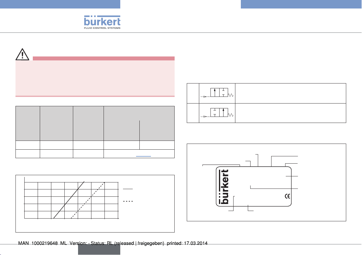
5.3.2 Pressure ranges
WARNING!
Risk of bursting due to overpressure!
If the device bursts, there is a risk of serious injury, chemical burns,
scalding.
▶ Do not exceed the maximum pilot and medium pressure. Observe
specifications on the rating plate.
Permitted pilot- and medium pressure:
Control
function
(CF)
CFA 5.5 10 10 6
CFB 2.2 7 see “Fig. 1”
Minimum
pilot
pressure
[bar]
Maximum
pilot
pressure
[bar]
Maximum medium pressure
Elastomer
(including
coated)
[bar]
PTFE and
Advanced
PTFE
Required minimum pilot pressure for control function B
depending on the medium pressure on one side:
10
8
6
4
2
0 1 2
Medium pressure [bar]
Fig. 1: Pressure graph, elastomer and Advanced PTFE diaphragm
6
3
4 5 6 7
Pilot pressure [bar]
english
Elastomer
(including coated)
PTFE and
Advanced PTFE
5.3.3 Permitted media
Control medium: neutral gases, air
Flow media: neutral gases and liquids, high-purity, sterile,
aggressive and abrasive media
5.4 Control functions
A
B
Closed in rest position by spring force
Open in rest position by spring force
5.5 Type label
Orifice (Diaphragm size)
Control function
Type
G1/4 Pmed 8,5 bar
Pilot 5,5-10 bar
S/N 1060
Made in Germany
Serial number
Fig. 2: Description of the type label
Identifications number
W36LP
Seal material
Body material
Connections, Max.
medium pressure
Pilot pressure
Page 7
Type 2031 INOX
Installation
6 INSTALLATION
DANGER!
Danger – high pressure!
▶ Before dismounting the lines and valves, turn off the pressure and
vent the lines.
Risk of electric shock!
▶ Before reaching into the device, switch off the power supply and
secure to prevent reactivation!
▶ Observe applicable accident prevention and safety regulations
for electrical equipment!
WARNING!
Risk of injury from improper installation, unintentional activation
of the system and uncontrolled restart!
▶ Installation must only be carried out by authorized technicians and
with the appropriate tools!
▶ Secure system from unintentional activation.
▶ Following installation, ensure a controlled restart.
Risk of crushing from moving pneumatic connection!
▶ When opening and closing the device, do not touch the moving
pneumatic connection.
▶ Do not reach into the area immediately above and below the
control air connection.
6.1 Before installation
• Before connecting the valve, ensure the lines are flush.
• The flow direction is optional.
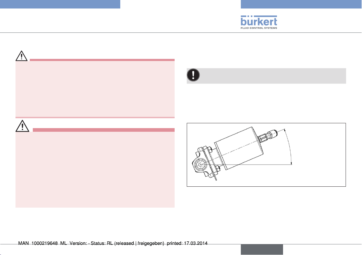
6.1.1 Installation position
Installation position: any, preferably with the actuator face up.
Installation for self-drainage of the body:
It is the responsibility of the installer and operator to ensure
self-drainage.
To ensure self-drainage:
• mark (-) on the body must be at 12 o’clock,
• hole in the diaphragm base must be at the lowest point to monitor
leakage.
Drainage angle -2°
Fig. 3: Installation position for self-drainage of the body
6.1.2 Preparatory work
→ Clean pipelines (sealing material, swarf, etc.).
→ Support and align pipelines.
english
7
Page 8
Type 2031 INOX
Installation
Devices with VG/VS welded body
Before welding the body, the actuator must be removed.
6.2 Installation
WARNING!
Risk of injury from incorrect installation!
Non-observance of the specified tightening torque is hazardous
as the device may be damaged.
▶ Observe tightening torque during installation.
6.2.1 Devices with VG/VS welded body
Before welding the body, the actuator must be removed.
Remove actuator and diaphragm from the body
Procedure for control function A:
→ Apply control air connection with compressed air (5.5 bar).
→ Loosen fastening screws in diagonal pairs and remove actuator
together with diaphragm from the body.
→ Weld body into the pipeline.
Procedure for control function B:
→ Loosen fastening screws in diagonal pairs and remove actuator
together with diaphragm from the body.
→ Weld body into the pipeline.
6.2.2 Installation
Installation for actuator with control function A:
→ Align diaphragm.
The mark tab of the diaphragm must be vertical to the flow
of direction.
→ Place actuator on the body.
→ Apply control air connection with compressed air (5.5 bar).
→ Lightly tighten fastening screws crosswise until the diaphragm is
situated between the body and actuator.
Do not tighten screws yet!
→ Switch diaphragm valve twice.
→ Tighten fastening screws.
Observe tightening torque (2.5 Nm)!
Installation for actuator with control function B:
→ Align diaphragm.
The mark tab of the diaphragm must be vertical to the flow
of direction.
→ Place actuator on the body.
→ Lightly tighten fastening screws crosswise until the diaphragm is
situated between the body and actuator.
Do not tighten screws yet!
→ Apply control air connection with compressed air (5.5 bar).
→ Switch diaphragm valve twice.
→ Tighten fastening screws.
Observe tightening torque (2.5 Nm)!
8
english
Page 9
Type 2031 INOX
Installation
6.3 Pneumatic connection
WARNING!
Risk of injury from unsuitable connection hoses!
Hoses which cannot withstand the pressure and temperature range
may result in hazardous situations.
▶ Use only hoses which are authorized for the indicated pressure
and temperature range.
▶ Observe the data sheet specifications from the hose manufacturers.
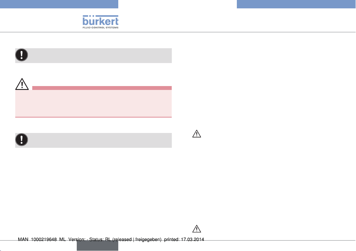
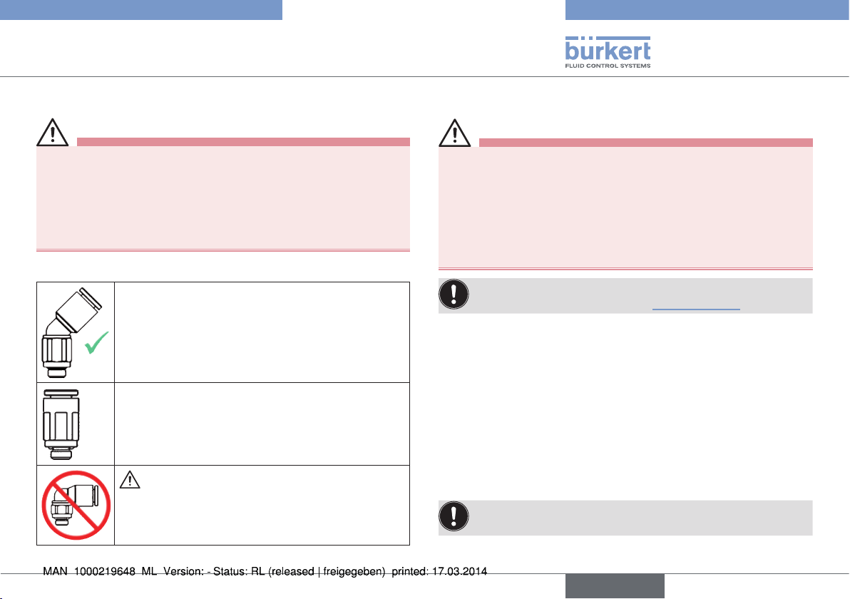
6.3.1 Control air connections
The 45° angle connection, which can be ordered
separately, is recommended for the control air connection! In this case the free-moving hose length
should be min. 250 mm. If the hose length is shorter,
the durability and function of the plug-in coupling
will be impaired!
If a straight control air connection is used, the freemoving hose length should be min. 400 mm.
If the hose length is shorter, the durability and
function of the plug-in coupling will be impaired!
Risk of crushing!
▶ Due to the risk of crushing, a 90° control air con-
nection must not be used!
7 START-UP
WARNING!
Risk of injury from improper operation!
Improper operation may result in injuries as well as damage to the
device and the area around it.
▶ Before start-up, ensure that the operating personnel are familiar
with and completely understand the contents of the manual.
▶ Observe the safety instructions and intended use.
▶ Only adequately trained personnel may start up the device.
Observe the type label specifications and information on pressure
and temperature values in chapter “Technical data”.
8 MAINTENANCE, CLEANING
8.1 Actuator
The actuator of the diaphragm valve is maintenance-free provided it is
used according to these operating instructions.
8.1.1 Wearing parts of the diaphragm valve
Parts which are subject to natural wear:
• Diaphragm
→ If leaks occur, replace the diaphragm with a new one.
A distended PTFE diaphragm may reduce the flow-rate.
english
9
Page 10

Type 2031 INOX
Transportation, Storage, Disposal
8.1.2 Inspection intervals
→ Check diaphragm for wear after a maximum 10
Muddy and abrasive media require correspondingly shorter
inspection intervals!
5
switching operations.
8.2 Cleaning
Commercially available cleaning agents can be used to clean the
surface of the device.
NOTE!
Before cleaning, check that the cleaning agents are compatible
with the body materials and seals.
9 TRANSPORTATION, STORAGE,
DISPOSAL
NOTE!
Transport and storage damage!
• Protect the device against moisture and dirt in shock-resistant
packaging during transportation and storage.
• Permitted storage temperature: -20 … +65 °C.
Storage with tightened body screws may result in permanent
deformation of the diaphragm.
• Slacken body screws for prolonged storage.
Damage to the environment caused by device components
contaminated with media.
• Dispose of the device and packaging in an environmentally
friendly manner!
10
english
Page 11

Typ 2031 INOX
Der Quickstart
InhaltsverzeIChnIs
1 DER QUICKSTART .................................................................................... 11
2 KONTAKTADRESSEN ..............................................................................11
3 BESTIMMUNGSGEMÄSSER GEBRAUCH ................................... 12
4 GRUNDLEGENDE SICHERHEITSHINWEISE .............................. 12
5 TECHNISCHE DATEN ............................................................................. 13
6 MONTAGE .....................................................................................................15
7 INBETRIEBNAHME ...................................................................................17
8 WARTUNG, REINIGUNG ........................................................................ 17
9 TRANSPORT LAGERUNG, ENTSORGUNG .................................18
1 DER QUICKSTART
Der Quickstart enthält wichtige Informationen.
▶ Quickstart sorgfältig lesen und Hinweise zur Sicherheit beachten.
▶ Quickstart muss jedem Benutzer zur Verfügung stehen.
▶ Die Haftung und Gewährleistung für Typ 2031 INOX entfällt, wenn
die Anweisungen des Quickstarts nicht beachtet werden.
Der Quickstart erläutert beispielhaft die Montage und Inbetriebnahme
des Geräts. Die ausführliche Beschreibung des Geräts finden Sie im
Internet unter: www.buerkert.de
1.1 Begriffsdefinition Gerät
Der in dieser Anleitung verwendeten Begriff „Gerät“ steht immer für
das Membranventil Typ 2031 INOX.
2 KONTAKTADRESSEN
Bürkert Fluid Control Systems / Sales Center
Christian-Bürkert-Str. 13-17
D-74653 Ingelfingen
Tel. + 49 (0) 7940 - 10 91 111
Fax + 49 (0) 7940 - 10 91 448
E-mail: info@de.buerkert.com
International
Die Kontaktadressen finden Sie im Internet unter: www.burkert.com
Bei Fragen Ihre Bürkert-Vertriebsniederlassung kontaktieren.
deutsch
11
Page 12

Typ 2031 INOX
Grundlegende Sicherheitshinweise
2.1 Darstellungsmittel
Warnung vor tödlichen oder schweren Verletzungen:
GEFAHR!
Warnt vor einer unmittelbaren Gefahr!
WARNUNG!
Warnt vor einer möglicherweise gefährlichen Situation!
Warnung vor mittelschweren oder leichten Verletzungen:
VORSICHT!
Warnt vor einer möglichen Gefährdung!
HINWEIS!
Warnt vor Sachschäden!
Wichtige Tipps und Empfehlungen.
→ markiert einen Arbeitsschritt den Sie ausführen müssen.
3 BESTIMMUNGSGEMÄSSER
GEBRAUCH
Das Membranventil Typ 2031 INOX ist für die Steuerung des Durchflusses von flüssigen und gasförmigen Medien konzipiert.
• Für den Einsatz die zulässigen Einsatzbedingungen beachten.
• Nur in einwandfreiem Zustand betreiben und auf sachgerechte
Lagerung, Transport, Installation und Bedienung achten.
4 GRUNDLEGENDE
SICHERHEITSHINWEISE
Gefahr durch hohen Druck!
▶ Vor dem Lösen von Leitungen oder Ventilen den Druck abschalten
und Leitungen entlüften.
Gefahr durch elektrische Spannung!
▶ Vor Eingriffen in das Gerät oder die Anlage, Spannung abschalten
und vor Wiedereinschalten sichern!
▶ Die geltenden Unfallverhütungs- und Sicherheitsbestimmungen
für elektrische Geräte beachten!
Quetschgefahr durch sich bewegenden pneumatischen
Anschluss!
▶ Beim Öffnen und Schließen des Geräts nicht den sich bewegen-
den pneumatischen Anschluss berühren.
▶ Nicht in den unmittelbaren Bereich oberhalb und unterhalb des
Steuerluftanschlusses fassen.
Verbrennungsgefahr/Brandgefahr bei Dauerbetrieb durch heiße
Geräteoberfläche!
▶ Das Gerät nicht mit bloßen Händen berühren.
▶ Das Gerät von leicht brennbaren Stoffen und Medien fernhalten.
12
deutsch
Page 13

Typ 2031 INOX
Technische Daten
Allgemeine Gefahrensituationen.
Zum Schutz vor Verletzungen ist zu beachten:
▶ Anlage/Gerät vor unbeabsichtigtem Betätigen sichern.
▶ In die Medienanschlüsse nur Medien einspeisen, die im Kapitel
„Technische Daten“ als Durchflussmedien aufgeführt sind.
▶ An Typ 2031 INOX keine inneren oder äußeren Veränderungen
vornehmen und nicht mechanisch belasten.
▶ Nur geschultes Fachpersonal darf Installations- und Instandhal-
tungsarbeiten ausführen.
▶ Nach Unterbrechung der elektrischen Versorgung für einen kon-
trollierten Wiederanlauf des Prozesses sorgen.
▶ Die allgemeinen Regeln der Technik einhalten.
5 TECHNISCHE DATEN
5.1 Konformität
Das Membranventil, Typ 2031 INOX ist konform zu den EG-Richtlinien
entsprechend der EG-Konformitätserklärung.
5.2 Normen
Die angewandten Normen, mit denen die Konformität zu den EG-Richtlinien nachgewiesen wird, sind in der EG-Baumusterprüfbescheinigung
und/oder der EG-Konformitätserklärung nachzulesen.
5.3 Betriebsbedingungen
5.3.1 Zulässige Temperaturen
Umgebungstemperatur: 0 °C … +60 °C
Mediumstemperatur: -10 °C … +140 °C
Zulässige Mediumstemperatur abhängig von Membranwerkstoff:
Membran-
werkstoff
EPDM -10 ... +130 °C Dampfsterilisation bis 140 °C
PTFE / EPDM -10 ... +130 °C Dampfsterilisation bis 140 °C
Advanced
PTFE kaschiert
1)
Die angegebene Mediumstemperatur gilt nur für Medien, welche die Membranwerkstoffe nicht angreifen. Das Verhalten des Mediums gegenüber der
Membran kann sich durch die Mediumstemperatur verändern.
Die Funktionseigenschaften, insbesondere die Lebensdauer der Membran,
können sich bei steigender Mediumstemperatur verschlechtern.
Mediumstem-
peratur
1)
-10 ... +90 °C -
Bemerkung
deutsch
13
Page 14

Typ 2031 INOX
P
A
P
A
2031 A 8,0 EPDM VA
00445286
Technische Daten
5.3.2 Druckbereiche
WARNUNG!
Berstgefahr bei Überdruck!
Beim Bersten des Geräts drohen schwere Verletzung, Verätzung,
Verbrühung.
▶ Den maximalen Steuer- und Mediumsdruck nicht überschreiten.
Angaben auf dem Typschild beachten.
Zulässiger Steuer- und Mediumsdruck:
Steuer-
funktion
(SF)
SFA 5,5 10 10 6
SFB 2,2 7 siehe „Bild 1“
Min.
Steuerdruck
[bar]
Max.
Steuerdruck
[bar]
Max. Mediumsdruck
[bar]
Elastomer
(inkl.
kaschiert)
PTFE und
Advanced
PTFE
Erforderlicher Mindeststeuerdruck bei Steuerfunktion B in
Abhängigkeit vom Mediumsdruck einseitig anstehend:
10
8
6
4
2
0 1 2
Mediumsdruck [bar]
Bild 1: Druckdiagramm, Elastomer- und Advanced PTFE Membran
14
3
4 5 6 7
Steuerdruck [bar]
Elastomer
(inkl. kaschiert)
PTFE und
Advanced PTFE
deutsch
5.3.3 Zulässige Medien
Steuermedium: neutrale Gase, Luft
Durchflussmedien: neutrale Gase und Flüssigkeiten, hochreine,
sterile, aggressive und abrasive Medien
5.4 Steuerfunktionen
A
B
In Ruhestellung durch Federkraft geschlossen
In Ruhestellung durch Federkraft geöffnet
5.5 Typschild
Nennweite (Membrangröße)
Steuerfunktion
Typ
G1/4 Pmed 8,5 bar
Pilot 5,5-10 bar
S/N 1060
W36LP
Seriennummer
Made in Germany
Identnummer des Geräts
Bild 2: Beschreibung des Typschildes
Dichtwerkstoff
Gehäusewerkstoff
Leitungsanschluss,
max. Mediumsdruck
Steuerdruck
Page 15

Typ 2031 INOX
Montage
6 MONTAGE
GEFAHR!
Verletzungsgefahr durch hohen Druck in der Anlage!
▶ Vor dem Lösen von Leitungen oder Ventilen den Druck abschal-
ten und Leitungen entlüften.
Gefahr durch elektrische Spannung!
▶ Vor Eingriffen in das Gerät oder die Anlage, Spannung abschal-
ten und vor Wiedereinschalten sichern!
▶ Die geltenden Unfallverhütungs- und Sicherheitsbestimmungen
für elektrische Geräte beachten!
WARNUNG!
Verletzungsgefahr bei unsachgemäßer Montage, ungewolltes
Einschalten der Anlage und unkontrollierten Wiederanlauf!
▶ Die Montage darf nur autorisiertes Fachpersonal mit geeignetem
Werkzeug durchführen!
▶ Anlage vor unbeabsichtigtem Betätigen sichern.
▶ Nach der Montage einen kontrollierten Wiederanlauf gewährleisten.
Quetschgefahr durch sich bewegenden pneumatischen Anschluss!
▶ Beim Öffnen und Schließen des Geräts nicht den sich bewegen-
den pneumatischen Anschluss berühren.
▶ Nicht in den unmittelbaren Bereich oberhalb und unterhalb des
Steuerluftanschlusses fassen.
6.1 Vor dem Einbau
• Vor dem Anschluss des Ventils auf fluchtende Rohrleitungen achten.
• Durchflussrichtung ist beliebig.
6.1.1 Einbaulage
Einbaulage: beliebig, vorzugsweise Antrieb nach oben.
Einbau für Selbstentleerung des Gehäuses:
Die Sicherstellung der Selbstentleerung liegt in der Verantwortung des Installateurs und Betreibers.
Um die Selbstentleerung zu gewährleisten muss die
• Markierung (-) auf dem Gehäuse auf 12 Uhr liegen,
• Bohrung im Membransockel, zur Überwachung der Leckage am
tiefsten Punkt sein.
Entleerungswinkel -2°
Bild 3: Einbaulage zur Selbstentleerung des Gehäuses
6.1.2 Vorbereitende Arbeiten
→ Rohrleitungen von Verunreinigungen säubern (Dichtungsmaterial,
Metallspäne etc.).
→ Rohrleitungen abstützen und ausrichten.
deutsch
15
Page 16

Typ 2031 INOX
Montage
Geräte mit VG/VS-Schweißgehäuse:
Vor dem Einschweißen des Gehäuses muss der Antrieb
demontiert werden.
6.2 Einbau
WARNUNG!
Verletzungsgefahr bei unsachgemäßem Einbau!
Das Nichtbeachten des Anziehdrehmoments ist wegen der möglichen Beschädigung des Geräts gefährlich.
▶ Anziehdrehmoment beim Einbau beachten.
6.2.1 Geräte mit VG/VS-Schweißgehäuse
Vor dem Einschweißen des Gehäuses muss der Antrieb
demontiert werden.
Antrieb und Membran vom Gehäuse abnehmen
Vorgehensweise bei Steuerfunktion A:
→ Steuerluftanschluss mit Druckluft (5,5 bar) beaufschlagen.
→ Befestigungsschrauben über Kreuz lösen und Antrieb mit Membran
vom Gehäuse abnehmen.
→ Gehäuse in die Rohrleitung einschweißen.
Vorgehensweise bei Steuerfunktion B:
→ Befestigungsschrauben über Kreuz lösen und Antrieb mit
Membran vom Gehäuse abnehmen.
→ Gehäuse in die Rohrleitung einschweißen.
6.2.2 Montage
Montage für Antrieb mit Steuerfunktion A:
→ Membran ausrichten.
Der Markierungslappen der Membran muss senkrecht zur
Durchflussrichtung stehen.
→ Antrieb auf das Gehäuse setzen.
→ Steuerluftanschluss mit Druckluft (5,5 bar) beaufschlagen.
→ Befestigungsschrauben über Kreuz leicht anziehen, bis die
Membran zwischen Gehäuse und Antrieb anliegt.
Schrauben noch nicht festziehen!
→ Membranventil zweimal schalten.
→ Befestigungsschrauben anziehen.
Anziehdrehmoment ( 2,5 Nm) beachten!
Montage für Antrieb mit Steuerfunktion B:
→ Membran ausrichten.
Der Markierungslappen der Membran muss senkrecht zur
Durchflussrichtung stehen.
→ Antrieb auf das Gehäuse setzen.
→ Befestigungsschrauben über Kreuz leicht anziehen, bis die
Membran zwischen Gehäuse und Antrieb anliegt.
Schrauben noch nicht festziehen!
→ Steuerdruckanschluss mit Druckluft (5,5 bar) beaufschlagen.
→ Membranventil zweimal schalten.
→ Befestigungsschrauben anziehen.
Anziehdrehmoment ( 2,5 Nm) beachten!
16
deutsch
Page 17

Typ 2031 INOX
Montage
6.3 Pneumatischer Anschluss
WARNUNG!
Verletzungsgefahr durch ungeeignete Anschlussschläuche!
Schläuche, die dem Druck- und Temperaturbereich nicht standhalten,
können zu gefährlichen Situationen führen.
▶ Nur Schläuche verwenden, die für den angegeben Druck- und
Temperaturbereich zugelassen sind.
▶ Die Datenblattangaben der Schlauchhersteller beachten.
6.3.1 Steuerluftanschlüsse
Als Steuerluftanschluss ist der separat bestellbare
45°-Winkelanschluss zu empfehlen!
Hier sollte die freibewegliche Schlauchlänge min.
250 mm betragen. Bei einer kürzeren Schlauchlänge wird die Haltbarkeit und Funktion der Steckkupplung beeinträchtigt!
Bei der Verwendung eines geraden Steuerluftanschlusses sollte die freibewegliche Schlauchlänge
min. 400 mm betragen.
Bei einer kürzeren Schlauchlänge wird die Haltbarkeit
und Funktion der Steckkupplung beeinträchtigt!
Quetschgefahr!
▶ Aufgrund der Quetschgefahr darf ein
90°-Steuerluftanschluss nicht verwendet werden!
7 INBETRIEBNAHME
WARNUNG!
Gefahr bei unsachgemäßem Betrieb!
▶ Vor der Inbetriebnahme muss gewährleistet sein, dass der Inhalt
der Bedienungsanleitung dem Bedienungspersonal bekannt ist
und vollständig verstanden wurde.
▶ Die Sicherheitshinweise und die bestimmungsgemäße Verwen-
dung müssen beachtet werden.
▶ Nur ausreichend geschultes Personal darf die Anlage/das Gerät
in Betrieb nehmen.
Typschildangaben und die Hinweise zu Druck- und Temperaturwerten in Kapitel „Technische Daten“ beachten.
8 WARTUNG, REINIGUNG
8.1 Antrieb
Der Antrieb des Membranventils ist, wenn für den Einsatz die Hinweise dieser Bedienungsanleitung beachtet werden, wartungsfrei.
8.2 Verschleißteile des Membranventils
Teile, die der natürlichen Abnutzung unterliegen sind:
• Membran
→ Bei Undichtheiten, die Membran gegen eine neue austauschen.
Eine ausgebeulte PTFE-Membran kann zur Reduzierung des
Durchflusses führen.
deutsch
17
Page 18

Typ 2031 INOX
Transport Lagerung, Entsorgung
8.3 Kontrollintervalle
→ Membran nach maximal 10
Schlammartige und abrasive Medien erfordern entsprechend
kürzere Kontrollintervalle!
5
Schaltspielen auf Verschleiß prüfen.
8.4 Reinigung
Zur Reinigung der Geräteoberfläche können handelsübliche Reinigungsmittel verwendet werden.
HINWEIS!
Die Verträglichkeit der Mittel mit den Gehäusewerkstoffen und
Dichtungen vor der Reinigung prüfen.
9 TRANSPORT LAGERUNG,
ENTSORGUNG
HINWEIS!
Transportschäden und Lagerschäden!
• Gerät vor Nässe und Schmutz geschützt in einer stoßfesten
Verpackung transportieren und lagern.
• Zulässige Lagertemperatur: -20 … +65 °C.
Lagerung mit festgezogenen Gehäuseschrauben kann zu bleibenden Verformungen der Membran führen.
• Gehäuseschrauben bei längerer Einlagerung lockern.
Umweltschäden durch von Medien kontaminierte Geräteteile.
• Gerät und Verpackung umweltgerecht entsorgen!
18
deutsch
Page 19

Typ 2031 INOX
Ce Quickstart
table des matIères
1 CE QUICKSTART ....................................................................................... 19
2 ADRESSES ................................................................................................... 19
3 UTILISATION CONFORME ................................................................... 20
4 CONSIGNES DE SÉCURITÉ FONDAMENTALES......................20
5 CARACTÉRISTIQUES TECHNIQUES .............................................21
6 MONTAGE .....................................................................................................23
7 MISE EN SERVICE .................................................................................... 25
8 MAINTENANCE, NETTOYAGE .............................................................25
9 TRANSPORT STOCKAGE, ÉLIMINATION ..................................... 26
1 CE QUICKSTART
Ce quickstart contient des informations importantes.
▶ Lire attentivement ce quickstart et tenir compte des consignes de
sécurité.
▶ Ce quickstart doit être mis à disposition de chaque utilisateur.
▶ La responsabilité et la garantie légale concernant le type 2000 INOX
sont exclues en cas de non-respect des instructions contenues
dans ce quickstart.
Quickstart explique au moyen d’exemples le montage et la mise en
service de l’appareil. Vous trouverez la description détaillée de l’appareil
sur Internet sous : www.buerkert.fr
1.1 Définition du terme
Le terme « appareil » utilisé dans ce manuel désigne toujours la vanne
à membrane Type 2031 INOX.
2 ADRESSES
Bürkert Fluid Control Systems / Sales Center
Christian-Bürkert-Str. 13-17
D-74653 Ingelfingen
Tel. + 49 (0) 7940 - 10 91 111
Fax + 49 (0) 7940 - 10 91 448
E-mail: info@de.buerkert.com
International
Les adresses se trouvent sur Internet sous: www.burkert.com
français
Si vous avez des questions, veuillez contacter votre filiale de
distribution Bürkert.
19
Page 20

Typ 2031 INOX
Consignes de sécurité fondamentales
2.1 Symboles
Mise en garde contre des blessures graves ou mortelles :
DANGER!
Met en garde contre un danger imminent.
AVERTISSEMENT !
Met en garde contre une situation éventuellement dangereuse.
Mise en garde contre des blessures moyennes ou légères :
ATTENTION !
Met en garde contre un risque éventuel.
REMARQUE !
Met en garde contre des dommages matériels.
Conseils et recommandations importants.
→ Identifie une opération que vous devez effectuer.
3 UTILISATION CONFORME
Vanne à membrane Type 2031 INOX a été conçue pour commander
le débit de fluides liquides et gazeux.
• Pour son utilisation, il convient de respecter les conditions d’exploitation et d’utilisation autorisées.
• Utiliser uniquement en parfait état et veiller au stockage, au transport,
à l’installation et à l’utilisation conformes.
4 CONSIGNES DE SÉCURITÉ
FONDAMENTALES
Danger dû à la haute pression.
▶ Avant de desserrer les conduites et les vannes, couper la pres-
sion et purger l’air des conduites.
Danger présenté par la tension électrique.
▶ Avant d’intervenir dans l’appareil ou l’installation, couper la ten-
sion et empêcher toute remise sous tension par inadvertance.
▶ Respecter les réglementations en vigueur pour les appareils élec-
triques en matière de prévention des accidents et de sécurité.
Risque de pincement dû à un raccord pneumatique en
mouvement.
▶ Lors de l’ouverture et de la fermeture de l’appareil, ne pas entrer
en contact avec le raccord pneumatique en mouvement.
▶ Ne pas mettre la main dans la zone immédiatement au-dessus
et en-dessous du raccord d’air de commande.
Risque de brûlures/d’incendie en fonctionnement continu dû à
des surfaces d’appareil brûlantes.
▶ Ne pas toucher l’appareil à mains nues.
▶ Tenir l’appareil éloigné des matières et fluides facilement
inflammables.
20
français
Page 21

Typ 2031 INOX
Caractéristiques techniques
Situations dangereuses d’ordre général.
Pour prévenir les blessures, respectez ce qui suit :
▶ Protéger l’installation/l’appareil contre tout actionnement
involontaire.
▶ Alimenter les raccords de fluides seulement avec les liquides
énumérés au chapitre « Caractéristiques techniques ».
▶ N’effectuer aucune modification interne ou externe sur le type 2031
INOX et ne pas le soumettre à des charges mécaniques.
▶ Seul du personnel qualifié peut effectuer l’installation et la
maintenance.
▶ Après une interruption de l’alimentation électrique ou pneuma-
tique, un redémarrage défini ou contrôlé du processus doit être
garanti.
▶ Les règles générales de la technique sont d’application pour
planifier l’utilisation et utiliser l’appareil.
5 CARACTÉRISTIQUES TECHNIQUES
5.1 Conformité
La vanne à membrane, Type 2031 INOX répond aux directives CE
conformément à la déclaration de conformité CE.
5.2 Normes
Les normes utilisées, avec lesquelles la conformité avec les directives
CE sont prouvées, figurent dans l’attestation CE de type et/ou la
déclaration de conformité CE.
5.3 Conditions d’utilisation
5.3.1 Températures admissibles
Température ambiante : 0 °C … +60 °C
Température du fluide : -10 °C … +140 °C
Température de fluide admissible en fonction du matériau de la membrane :
Matériau du
membrane
EPDM -10 ... +130 °C
PTFE / EPDM -10 ... +130 °C
Advanced
stratifié PTFE
1)
La température du fluide indiquée ne s’applique qu’aux fluides n’attaquant
pas les matériaux de la membrane. Le comportement du fluide par rapport
à la membrane peut changer en fonction de la température du fluide.
Les propriétés fonctionnelles, notamment la durée de vie de la membrane,
peuvent se détériorer au fur et à mesure que la température du fluide
augmente.
Température
du fluide
1)
-10 ... +90 °C -
Remarque
Stérilisation à la vapeur jusqu’à
Stérilisation à la vapeur jusqu’à
140 °C
140 °C
français
21
Page 22

Typ 2031 INOX
P
A
P
A
2031 A 8,0 EPDM VA
00445286
Caractéristiques techniques
5.3.2 Plages de pression
AVERTISSEMENT !
Risque de rupture en cas de surpression.
En cas de rupture de l’appareil, il y a risque de graves blessures,
de brûlures par acide et autres.
▶ Ne pas dépasser les pressions de pilotage et de fluide maximales.
Respecter les indications figurant sur la plaque signalétique.
Pression de pilotage et pression du fluide admissible :
Fonction
de com-
mande
(CF)
CFA 5,5 10 10 6
CFB 2,2 7 voir « Fig. 1 »
Pression
de pilotage
minimale
[bar]
Pression
de pilotage
maximale
[bar]
Pression du fluide
maximale [bar]
Élastomère
(y compris
stratifié)
PTFE et
PTFE
advanced
Pression de pilotage minimale nécessaire pour la fonction de commande B selon la pression du fluide appliquée sur un seul côté :
10
8
6
4
2
0 1 2
Pression du fluide [bar]
Fig. 1 : Diagramme de pression, membrane en élastomère et en PTFE advanced
22
Pression de pilotage [bar]
3
4 5 6 7
Élastomère (y
compris stratifié)
PTFE et PTFE
advanced
5.3.3 Fluides admissibles
Fluide de commande: gaz neutres, air
Fluides transportés: gaz et liquides neutres, fluides très purs, sté-
riles, agressifs et abrasifs
5.4 Fonctions
A
B
Fermé en position de repos par l’action d’un
ressort
Ouvert en position de repos par l’action d’un
ressort
5.5 Plaque signalétique
Diamètre nominal
(Taille de membrane)
Fonction
Type
G1/4 Pmed 8,5 bar
Pilot 5,5-10 bar
S/N 1060
Made in Germany
N° de série
Fig. 2 : Description de la plaque signalétique
N° d’identification
W36LP
Matériau du joint
Matériau du corps
Type de raccord,
pression du fluide
maximale
Pression de
pilotage
français
Page 23

Typ 2031 INOX
Montage
6 MONTAGE
DANGER !
Danger dû à la haute pression.
▶ Avant de desserrer les conduites et les vannes, couper la pres-
sion et purger l’air des conduites.
Danger présenté par la tension électrique.
▶ Avant d’intervenir dans l’appareil ou l’installation, couper la tension
et empêcher toute remise sous tension par inadvertance.
▶ Respecter les réglementations en vigueur pour les appareils élec-
triques en matière de prévention des accidents et de sécurité.
AVERTISSEMENT !
Risque de blessures dû à un montage non conforme, la mise
en marche involontaire de l’installation et au redémarrage
non contrôlé.
▶ Le montage doit être effectué uniquement par un personnel qualifié
et habilité disposant de l’outillage approprié.
▶ Empêcher tout actionnement involontaire de l’installation.
▶ Garantir un redémarrage contrôlé après le montage.
Risque de pincement dû à un raccord pneumatique en mouvement.
▶ Lors de l’ouverture et de la fermeture de l’appareil, ne pas entrer
en contact avec le raccord pneumatique en mouvement.
▶ Ne pas mettre la main dans la zone immédiatement au-dessus
et en-dessous du raccord d’air de commande.
6.1 Avant le montage
• Avant de raccorder la vanne, veiller à ce que les tuyauteries soient
correctement alignées.
• Le sens de débit est indifférent.
6.1.1 Position de montage
Position de montage: au choix, de préférence actionneur vers le haut.
Montage pour la vidange automatique du corps :
Il est de la responsabilité de l’installateur et de l’exploitant de
garantir la vidange automatique.
Pour une vidange automatique, il faut que :
• le marquage (-) sur le corps se trouve sur 12 h,
• l’alésage dans le socle de la membrane se trouve au point le plus
bas pour surveiller les fuites éventuelles
Angle de vidange -2°
Fig. 3 : Position de montage permettant au corps de se vider
automatiquement
6.2 Travaux préparatoires
→ Nettoyer les tuyauteries (matériau d’étanchéité, copeaux de
métal, etc.).
→ Soutenir et aligner les tuyauteries.
français
23
Page 24

Typ 2031 INOX
Montage
Appareils avec corps à souder VG/VS :
Avant le soudage du corps, il est nécessaire de démonter
l’actionneur.
6.3 Montage
AVERTISSEMENT !
Risque de blessures dû à un montage non conforme.
Le non-respect du couple de serrage est dangereux du fait de
l’endommagement possible de l’appareil.
▶ Respecter le couple de serrage lors du montage.
6.3.1 Appareils avec corps à souder VG/VS
Avant le soudage du corps, il est nécessaire de démonter
l’actionneur.
Retirer l’actionneur et la membrane du corps
Procédure à suivre pour la fonction de commande A :
→ Appliquer de l’air comprimé à 5,5 bar au raccord d’air de commande.
→ Desserrer les vis de fixation en croix et retirer l’actionneur avec la
membrane du corps.
→ Souder le corps dans la tuyauterie.
Procédure à suivre pour la fonction de commande B :
→ Desserrer les vis de fixation en croix et retirer l’actionneur avec la
membrane du corps.
→ Souder le corps dans la tuyauterie.
6.3.2 Montage
Montage de l’actionneur avec la fonction de commande A :
→ Aligner la membrane.
La patte de marquage de la membrane doit être verticale
par rapport au sens du débit.
→ Placer l’actionneur sur le corps.
→ Appliquer de l’air comprimé à 5,5 bar au raccord d’air de commande.
→ Serrer les vis de fixation légèrement en croisant jusqu’à ce que la
membrane soit en contact entre le corps et l’actionneur.
Ne pas encore serrer les vis à fond !
→ Actionner deux fois la vanne à membrane.
→ Serrer les vis de fixation.
Respecter le couple de serrage (2,5 Nm) !
Montage de l’actionneur avec la fonction de commande B :
→ Aligner la membrane.
La patte de marquage de la membrane doit être verticale
par rapport au sens du débit.
→ Placer l’actionneur sur le corps.
→ Serrer les vis de fixation légèrement en croisant jusqu’à ce que la
membrane soit en contact entre le corps et l’actionneur.
Ne pas encore serrer les vis à fond !
→ Appliquer de l’air comprimé à 5,5 bar au raccord d’air de commande.
→ Actionner deux fois la vanne à membrane.
→ Serrer les vis de fixation.
Respecter le couple de serrage (2,5 Nm) !
24
français
Page 25

Typ 2031 INOX
Mise en service
6.4 Raccordement pneumatique
AVERTISSEMENT !
Risque de blessures dû aux tuyaux flexibles de raccordement
non appropriés.
Les tuyaux flexibles ne résistant pas à la plage de pression et de
température peuvent entraîner des situations dangereuses.
▶ Utiliser uniquement des tuyaux flexibles homologués pour la plage
de pression et de température indiquée.
▶ Respecter les indications figurant sur la fiche technique du fabri-
cant de tuyaux flexibles.
6.4.1 Control air connections
Nous recommandons le raccord angulaire de 45° à commander séparément pour faire office de raccord d’air de
commande.
À cet effet, la longueur de tuyau flexible bougeant
librement doit être de 250 mm min. En cas de tuyau
flexible plus court, la durée de vie et le fonctionnement du
raccord enfichable seront réduits.
En cas d’utilisation d’un raccord d’air de commande droit,
la longueur de tuyau flexible bougeant librement doit être
de 400 mm min.
En cas de tuyau flexible plus court, la durée de vie et le
fonctionnement du raccord enfichable seront réduits.
Risque de pincement.
▶ Il est interdit d’utiliser un raccord d’air de com-
mande de 90° en raison du risque de pincement.
7 MISE EN SERVICE
AVERTISSEMENT !
Risque de blessures dû à une exploitation non conforme !
Une utilisation non conforme peut entraîner des blessures et
endommager l’appareil et son environnement.
▶ Avant la mise en service, il faut s’assurer que le contenu du
manuel est connu et parfaitement compris par les opérateurs.
▶ Respecter les consignes de sécurité et l’utilisation conforme.
▶ L’appareil/l’installation doit être mis(e) en service uniquement
par un personnel suffisamment formé.
Respecter les indications de la plaque signalétique et les
consignes concernant la pression et les valeurs de températures au chapitre « Caractéristiques techniques ».
8 MAINTENANCE, NETTOYAGE
8.1 Actionneur
À condition de respecter les consignes de ces instructions de service,
l’actionneur de la vanne à membrane ne nécessite aucun entretien.
8.1.1 Pièces d’usure de la vanne à
membrane
Les pièces soumises à une usure naturelle sont les suivantes :
• Membrane
→ En cas de fuite, remplacer la membrane par une neuve.
français
25
Page 26

Typ 2031 INOX
Transport Stockage, Élimination
Une membrane PTFE déformée peut entraîner une réduction
du débit.
8.1.2 Intervalles de contrôle
→ Contrôler l’usure de la membrane après au maximum 10
de commutation.
Les fluides boueux et abrasifs exigent des intervalles de contrôle
plus rapprochés.
5
cycles
8.2 Nettoyage
Pour nettoyer la surface de l’appareil, des produits de nettoyage
courants peuvent être utilisés.
REMARQUE !
Vérifier la compatibilité des produits avec les matériaux du boîtier
et les joints avant d’effectuer le nettoyage.
9 TRANSPORT STOCKAGE,
ÉLIMINATION
REMARQUE !
Dommages dus au transport/au stockage.
• Transporter et stocker l’appareil à l’abri de l’humidité et des
impuretés et dans un emballage résistant aux chocs.
• Température de stockage autorisée : -20 … +65 °C.
Le stockage avec les vis de corps serrées à fond peut entraîner
des déformations définitives de la membrane.
• Desserrer les vis de corps en cas de stockage prolongé.
Dommages à l’environnement causés par des pièces d’appareil
contaminées par des fluides.
• Éliminer l’appareil et l’emballage dans le respect de
l’environnement.
26
français
Page 27

Page 28

www.burkert.com
 Loading...