

Page 1
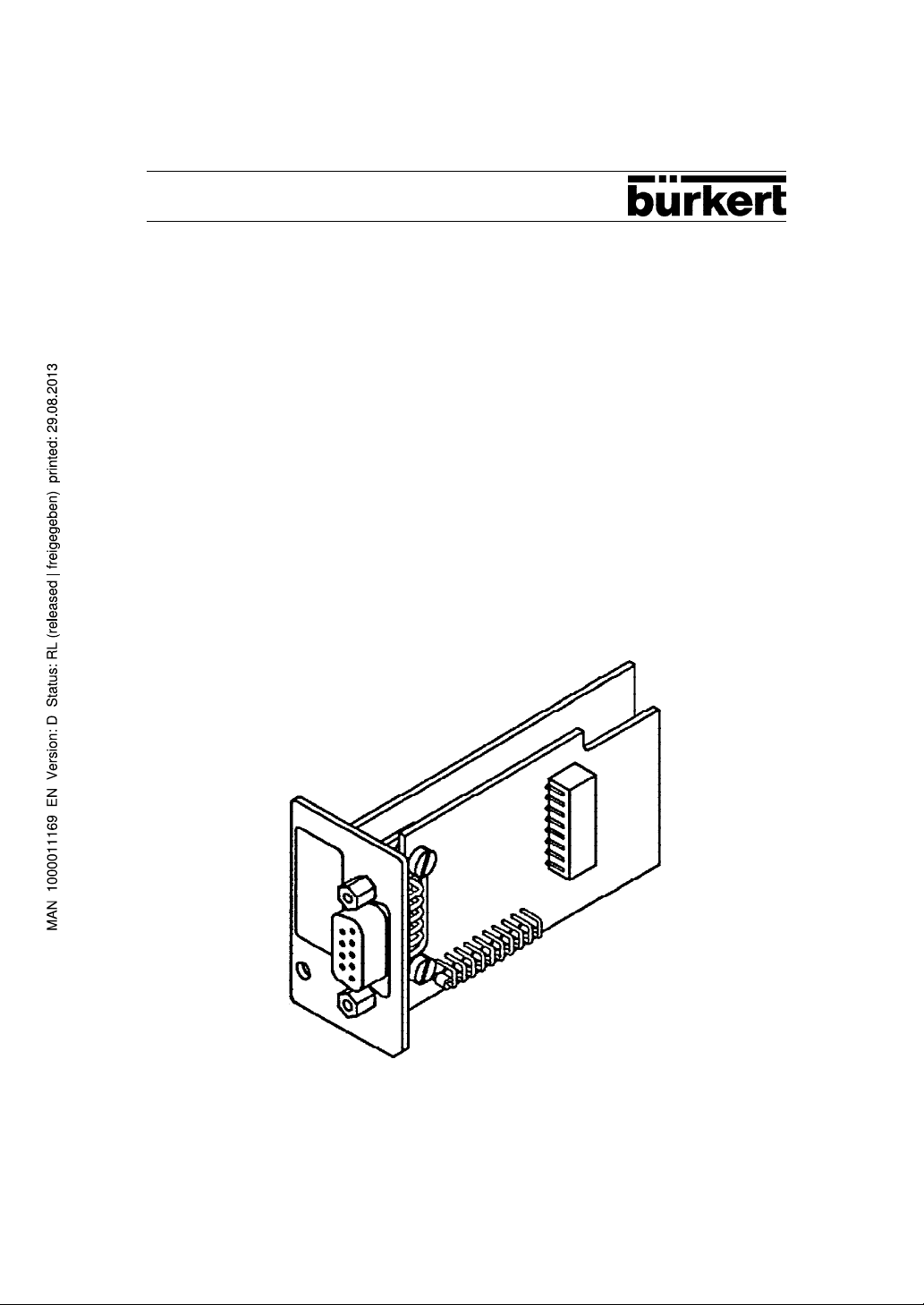
Operating Instructions
Interface RS 232 and
Interface RS 485 / Profibus
for
Digital Industrial Controller Type 1110
and
Digital Batch Controller Type 1115
1
Page 2

Contents
1 Block diagram of functions ...................................................... 2
2 Notices concerning use and safety.......................................... 3
3 System description .................................................................... 4
3.1 Introduction ................................................................................ 4
3.2 Switch configuration ................................................................. 4
3.3 Connector pin assignment........................................................ 5
3.4 Installation.................................................................................. 5
4 Profibus....................................................................................... 6
4.1 Objects for Digital Industrial Controller Type 1110 ................ 6
4.2 Error list operating errors ......................................................... 14
4.3 Objects for Digital Batch Controller Type 1115 ...................... 15
4.4 Error list operating errors ......................................................... 19
5 RS 232-Protocol ......................................................................... 20
5.1 Transmission format .................................................................. 20
5.2 Transmission protocol ............................................................... 20
6 Configuration of the interfaces ................................................ 22
2
Page 3
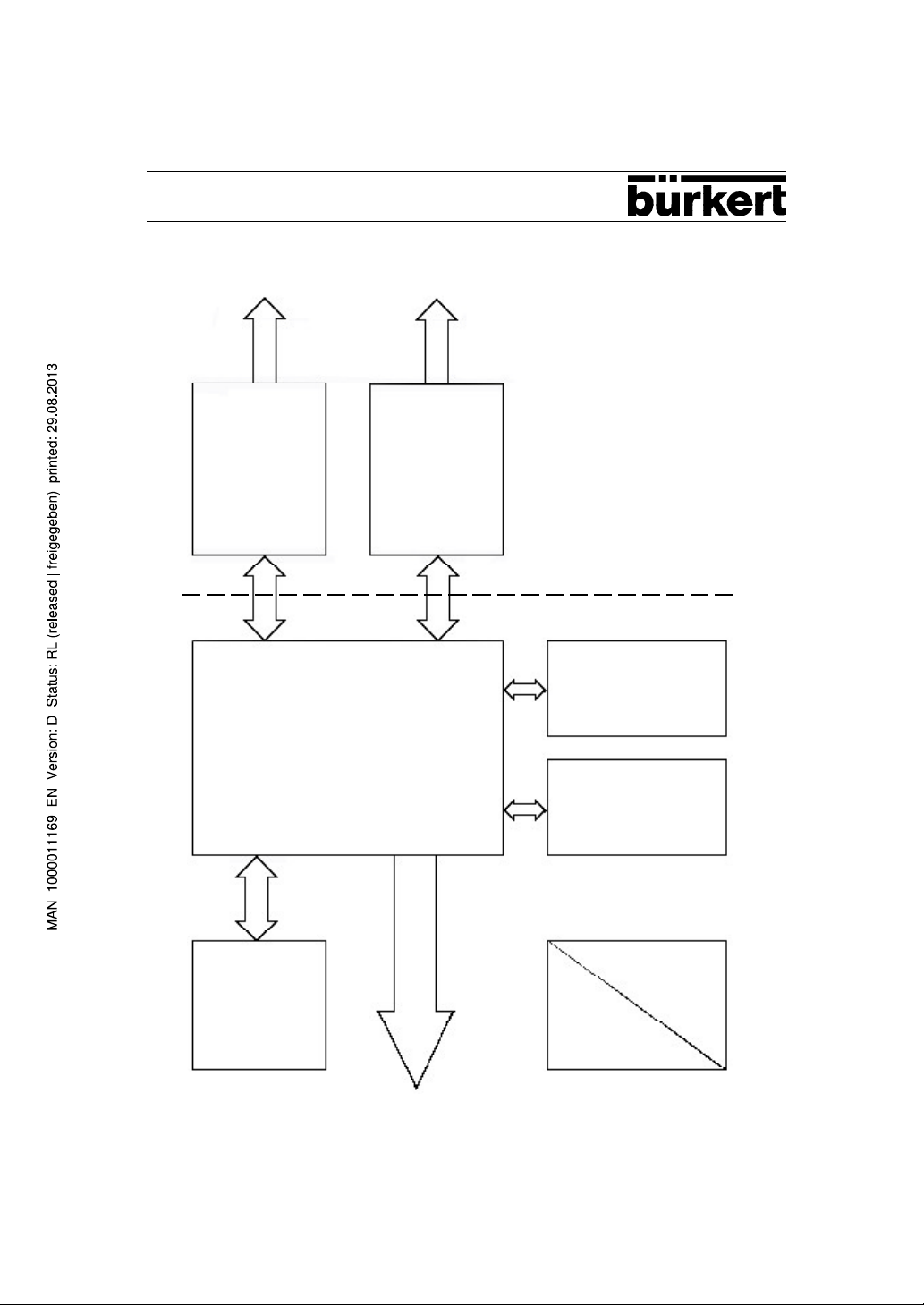
1 Block diagram of functions
Driver RS 232 Driver RS 485
Interface card RS 232, RS 485 / Profibus
CPU 80C51FQA
galvanic separation
OT-PROM 64 Kbit
Clock 12/16 MHz
RAM 32 Kbit
DC
DC
3
Page 4

2 Notices concerning use and safety
In order to ensure a perfect functioning and a long working life of the interface card
when using this card, the user is requested to follow this operating instructions and the
operating instructions of the digital units to be used with this card (e.g. Digital Industrial
Controller
Type 1110 or Digital Batch Controller Type 1115) as well as to maintain the operating
conditions and to observe the allowed specifications according to the data sheet.
Installation and maintenance personnel must be trained and qualified for this work.
All possibilites of unauthorized operation with the resulting impairment of the process are
to be ruled out through precautionary measures. For maintenance purposes, safe
electrical disconnectors and media technical shut off devices are to be provided. Should
the unit equipped with the interface card be part of a complex automation system, then
the automation system must be provided with a defined and controlled restart process
as specified in the instructions for starting up again following an interruption.
When operating the device or carrying out service and repair work on the equipment, the
regulations in force for the prevention of accidents and the safety of electrical
equipment must be observed.
Commissioning, start-up and repairs may only be carried out through authorized
specialists.
4
Page 5
3 System description
3.1 Introduction
The Digital Industrial Controller 1110 as well as the Digital Batch Controller 1115 can be
equipped with a digital interface.
Using the additional card required for this purpose, either a point-to-point connection can
be erected through RS 232 or, by using additional equipment, a network can be built
through
RS 485/Profibus.
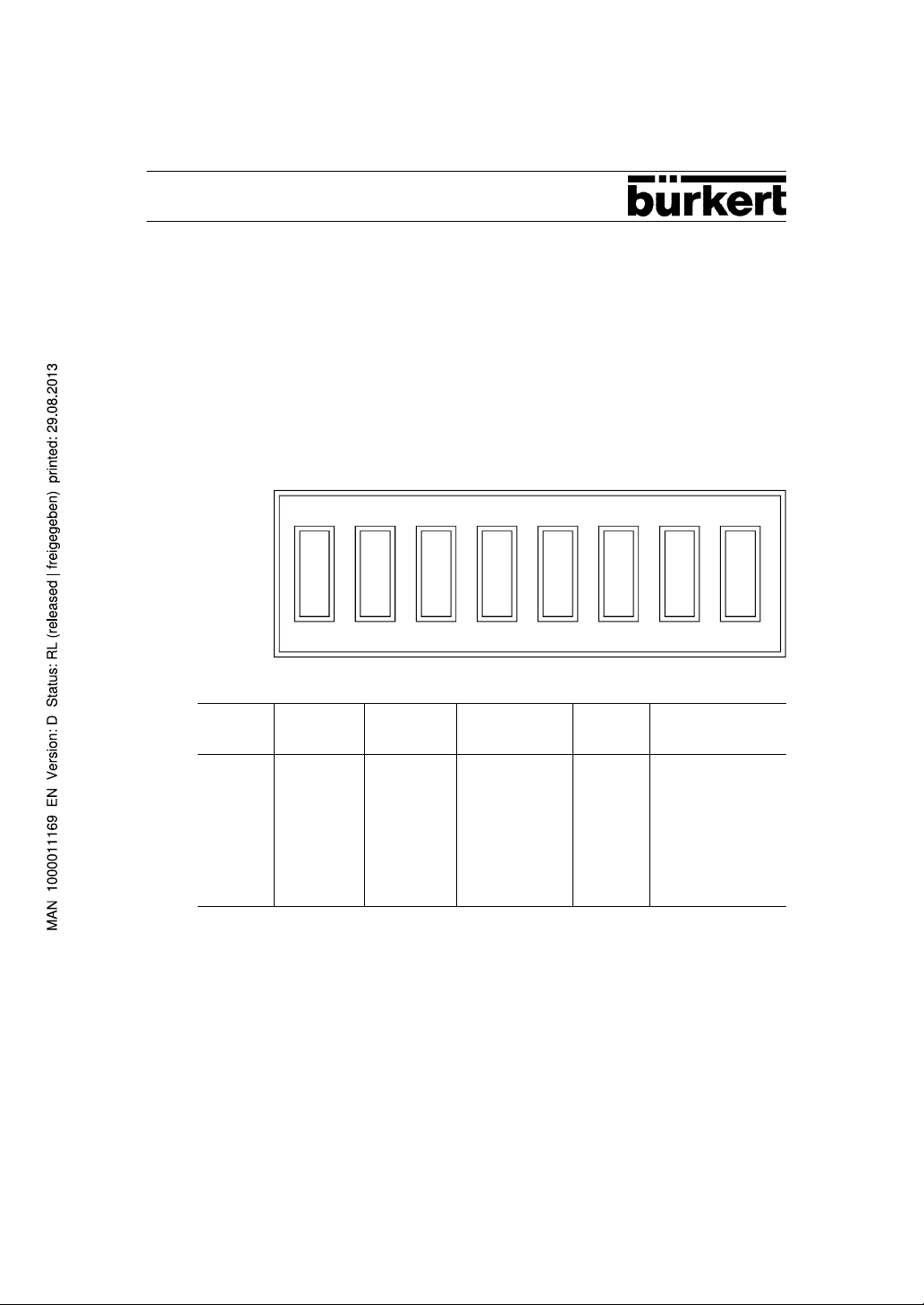
3.2 Switch configuration
ON
1 2 3 4 5 6 7 8
RS 232 RS 485 RS 485 Profibus Profibus
add. equipment add. equipment
1 OFF OFF ON OFF ON
2 OFF OFF ON OFF ON
3 OFF ON ON ON ON
4 OFF ON ON ON ON
5 ON OFF OFF OFF OFF
6 ON OFF OFF OFF OFF
7 OFF ON ON ON ON
8 OFF OFF OFF ON ON
5
Page 6
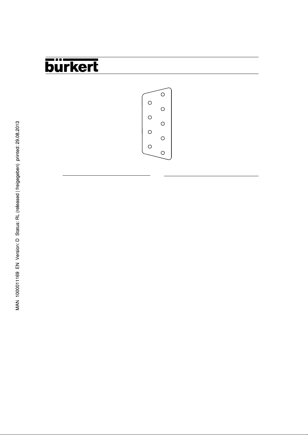
3.3 Connector pin assignment D sub-connector 9 terminal/female
9
5
6
1
RS 232 RS 485 / Profibus
2 TxD 3 reception/transmission data
positive
3 RxD 8 reception/transmission data
negative
5 GND 5 GND
3.4 Installation
The maximum bus baud rate is 500 KBaud.
The following performance lengths can be achieved:
1200 m 9.6 / 19.2 / 93.75 KBaud
600 m 187.5 KBaud
200 m 500 KBaud
twisted double-wiring, shielded Notice:
standard wiring diameter 0.22 mm
doubled wiring length at 0.5 mm
2
2
for additional information refer to the
Profibus standard DIN 19245
To operate, remove equipment from the mains supply. Remove plastic inset from back of
equipment and insert interface card.
After reconnecting to mains supply, the following settings are necessary in serial menu
supplements:
1. address
(for Profibus, the baud rate adjusts automatically)
2. additionally for RS 232/485:
parity / odd / even / none
baud rate 4800 / 9600
6
Page 7
4. Profibus
Profibus is standardized according to DIN 19 245.
We support the following features:
Get OV (long)
Read
Write.
FMS features supported are therefore:
80 30 00 00 00 00
Our equipment is slave.
We provide the following communication references:
Index Typ SAP
2 MSZY 3
3 MSAZ 4
4 MSZY 5
5 MSAZ 6
6 MSZY 7
7 MSAZ 8
8 MSZY 9
9 MSAZ 10
(Master Slave Cyclic / Acyclic)
4.1 List of the objects for the Digital Industrial Controller Type 1110
Structure of the masks
Within a mask, the variable required for the configuration from among the following will
be represented. Sequence: 1st variable = LSB
LSB represented.
1- is required in the configuration
0- is not required in the configuration
20 UINT16 Mask process values
21 UINT8 Hardware unit
22 FLP X1 measurable value channel 1
23 FLP X2 measurable value channel 2
24 FLP W1 set point main controller or single controller
25 FLP Yh correcting variable main controller at cascade
26 FLP W2 set point support controller at cascade
27 FLP Y2h correcting variable heating/continuous
28 FLP Y2k correcting variable cooling
29 FLP Xdh control offset main controller
7
Page 8

30 FLP Xd2 control offset support/single controller
31 UINT8 Relay position output relay
0: non-active
1: active
Bit 0 = position relay 1
Bit 1 = position relay 2
Bit 2 = alarm relay 2
Bit 3 = alarm relay 2
valve`s
32 UINT8 Reading-in condition of binary input (please follow Index 182/181)
33 UINT8 Reading-in condition of binary input (please follow Index 183/184)
34 UINT8 Condition of set point ramp
35 UINT8 Condition of set point tracking (SPT)
36 UINT8 Condition of main controller (only with cascade controller)
37 UINT8 Condition of support controller
Pulse valve: Not the current relay condition, but rather the
switching condition is set.
0: off
1: on
0: off
1: on
0: manual
1: automatic
2: manual
3: manual
0: manual
1: automatic
2: manual
3: manual
8
Page 9

38 UINT8 Controller errors
x x x x x x x x
39 UINT16 Input errors
x x x x x x x x x
2
2
0 : EEPROM-data configuration OK
1 : EEPROM-data configuration defect
0 : EEPROM-data parametration OK
1 : EEPROM-data parametration defect
0 : EEPROM-data former condition OK
1 : EEPROM-data former condition defect
0 : EEPROM-data calibration data OK
1 : EEPROM-data calibration data defect
0 : no error at the binary input
1 : error at the binary input
0 : no error at the analogue output
1 : error at the analogue output
0 : no error at input 1
1 : error at input 1
0 : no error at input 2
1 : error at binary input 2
0 : no error at the thermocouple input
1 : error at the thermocouple input
0 : no error at the PT100 input
1 : error at the PT100 input
0 : no error at the first standard signal U input 1
1 : error at the first standard signal U input 1
0 : no error at the first standard signal I input 1
1 : error at the first standard signal I input 1
0 : no error at the first frequency input
1 : error at the first frequency input
0 : no error at the second frequency input
1 : error at the second frequency input
0 : no error at the second standard signal U input
1 : error at the second standard signal U input 2
0 : no error at the second standard signal I input
1 : error at the second standard signal I input 2
0 : no NTC error
1 : NTC error */
40 UINT8 Operating errors
refer to error list 3.2
41 UINT8 Configuration/parametration
0: reserve
1: process
2: configuration
3: parametration
9
Page 10

42 UINT8 Remote / local switching
0: local
1: remote
43 UINT16 Alteration 1
44 UINT16 Alteration 2
45 UINT8 Address / station address of the unit
49 UINT8 PT 100 Type (connection type)
The contents of the following indices can be automatically
altered by the internal processor; i.e. meaningless user
parametrations will be automatically corrected.
Index Bit Index Bit
57 0 81 6
56 1 92 7
85 2 91 8
84 3 101 9
58 4 125 10
82 5 170 11
The contents of the following indices can be automatically
altered by the internal processor; i.e. meaningless user
parametrations will be automatically corrected.
Index Bit Index Bit
61 0 171 5
63 1 76 6
66 2 166 7
145 3 181 8
156 4
0: 3 conductors
1: 4 conductors
50 UINT16 Mask configuration 1st input
51 UINT8 Type 1st input
10
0: 0 - 10 V
1: 0 - 20 mA
2: 4 -2 0 mA
3: frequency
4: Pt 100
5: thermocouple J
6: thermocouple K
7: thermocouple T
8: thermocouple R
9: thermocouple S
Page 11

52 UINT8 Vst reference junction compensation ext / int at thermocouple
0: internal
1 external
53 UINT8 Rad evolving a root
54 UINT16 Fre final value frequency input
55 FLP Fg1 limit frequency filter
56 FLP X1u minimum value 1st input (lower scale value)
57 FLP X1o maximum value 1st input (upper scale value)
58 FLP Xvu minimum value ratio input (lower scale value)
59 FLP Xvo maximum value ratio input (upper scale value)
60 UINT16 Mask configuration limit of correcting variable
61 FLP Yu lower limit main controller
62 FLP Yo upper limit main controller
63 FLP Y2hu lower limit heating/continuous
64 FLP Y2ho upper limit heating/continuous
65 FLP Y2ku lower limit cooling
66 FLP Y2ko upper limit cooling
70 UINT16 Mask structure / configuration 2nd input
71 UINT8 Structure of the controller
72 UINT8 Type 2nd input
0: no
1: yes
0: standard controller
1: external set point
2: ratio controller
3: disturbance-variable compensation
4: reserve
5: cascade controller
0: 0 - 10 V
1: 0 - 20 mA
2: 4 -2 0 mA
3: frequency
73 UINT8 Evolving a root
0: off
1: on
74 UINT16 Fre2 final value frequency input
75 FLP Fg2 limiting frequency filter
76 FLP X2u minimum value 2. input (lower scale value)
77 FLP X2o maximum value 2. input (upper scale value)
11
Page 12

80 UINT16 Mask configuration alarm function
81 FLP X1- lower alarm limit actual value
82 FLP X1+ upper alarm limit actual value
83 FLP A1 Hy alarm hysteresis actual value
84 FLP A1Q- lower alarm limit absolute value ratio regulation
85 FLP A1Q+ upper alarm limit absolute value ratio regulation
86 FLP A1QH hysteresis absolute value ratio regulation
87 UINT8 Mode alarm function
90 UINT16 Mask configuration set point limits
91 FLP W1u lowest set point limit
92 FLP W1o upper set point limit
100 UINT16 Mask configuration set point ramp
102 FLP D gradient (standard: W/min)
103 UINT8 Pon ramp at alteration of set point
110 UINT16 Mask configuration Set Point Tracking
111 FLP SPTE final value set point tracking (read only!)
112 FLP SPTD gradient set point tracking
113 UINT8 SPT on / off
120 UINT16 Mask configuration disturbance-variable compensation
121 FLP kps amplification
122 FLP Tds derivative-action time
123 FLP Ts delay time
124 FLP Xsd insensitiveness
125 FLP X0 operating point
0: absolute alarm
1: band alarm
0: off
1: on
0: off
1: on
140 UINT16 Mask configuration main controller
141 FLP kp1 amplification
142 FLP Tn reset time
143 FLP Tv derivative-action time
144 FLP Ratio derivative-action time / delay time
145 FLP Y0 operating point
146 FLP Xtb insensitiveness
12
Page 13

150 UINT16 Mask configuration support / single controller
151 FLP kp1 amplification heating / continuous
152 FLP kp2 amplification cooling
153 FLP Tn reset time
154 FLP Tv derivative-action time
155 FLP Ratio derivative-action time / delay time
156 FLP Y0 operating point
157 FLP Xtb insensitiveness
158 UINT8 direction of effect
0: positive direction of effect
1: inverted direction of effect
160 UINT16 Mask configuration output
161 UINT8 Function output
0: reserve
1: 2-point
2: 3-point
3: 3-point step (without external feedback)
4: continuous
5: position (with external feedback)
162 UINT8 Type continuous output
0: 0 - 10 V
1: 0 - 20 mA
2: 4 - 20 mA
163 UINT8 Pulse valve yes / no (with 2 point output)
0: no pulse valve
1: pulse valve
164 FLP Ty motor running time
165 FLP Xsh hysteresis
166 FLP Xsd insensitiveness
167 FLP T+ cycle time heating
168 FLP T- cycle time cooling
169 FLP Gt gear lot
170 FLP Olp overlapping range
171 FLP Ys safety value
180 UINT16 Mask configuration binary input / output
181 UINT8 Function binary input
0: no (no function)
1: alarm
2: manual / automatic
3: external / internal W (if index 71 = 1)
4: safety value
182 UINT8 Effect binary input
0: normal
1: inverted
13
Page 14

183 UINT8 Function binary output
0: no (no function)
1: alarm
2: manual / automatic
3: feeler break
184 UINT8 Effect binary output
190 UINT16 Mask code
191 UINT16 Code priority 1 (configuration)
192 UINT16 Code priority 2 (parametration)
193 UINT16 Code priority 3 (process operation)
200 UINT16 Mask configuration other
201 UINT8 Language
202 UINT8 Representation 2nd line
203 UINT8 Resolution bar graph
0: normal
1: inverted
0: German
1: English
2: French
0: actual value
1: bar graph
14
Page 15

4.2 Error list operating errors
Index 40
1: Acknowledged
2: Access OK
3: Data base not up to date
4: Value outside of value range
5: Value cannot be described in current condition
6: Another enquiry is still in progress
7: Main controller cannot be operated
8: Main controller contains wrong value
9: Support / single controller cannot be operated
10: Support / single controller contains wrong value
11: W main controller / single controller cannot be operated
12: W main controller / single controller contains wrong value
13: W support controller cannot be operated
14: W support controller contains wrong value
15: Yh main controller cannot be operated
16: Yh main controller contains wrong value
17: Y2h support / single controller cannot be operated
18: Y2h support / single controller contains wrong value
19: Y2k support / single controller cannot be operated
20: Y2k support / single controller contains wrong value
21: Y2h 3-point step cannnot be operated
22: Y2h 3-point step contains wrong value
23: Set point ramp cannot be operated
24: Set point ramp contains wrong value
25: Parametration is not possible
26: Configuration is not possible
27: Parametration is not possible → not part of process operation
28: Parametration is not possible → LOCAL in configuration
29: Configuration is not possible → not part of process operation
15
Page 16

4.3 List of the objects for Digital Batch Controller Type 1115
20 UINT16 Mask process values
21 UINT8 Hardware unit
22 FLP Actual volume 1
23 FLP Actual volume 2
24 FLP Actual volume 1 + 2
25 FLP Residual volume 1
26 FLP Residual volume 2
27 FLP Residual volume 1 + 2
28 FLP Required volume 1
29 FLP Required volume 2
30 FLP Required volume 1 + 2
31 FLP Exact limit 1
32 FLP Exact limit 2
33 FLP Throughput 1
34 FLP Throughput 2
35 FLP Throughput 1 + 2
36 FLP Total volume 1
37 FLP Total volume 2
38 FLP Total volume 1+2
39 UINT8 Condition 1
0: Channel turned off
1: Filling procedure stopped
2: Approximate proportioning
3: Exact proportioning
4: Runoff
5: Filling procedure completed
6: Channel placed back
40 UINT8 Condition 2
41 UINT8 Total condition
42 UINT8 Starting time in hours
43 UINT8 Starting time in minutes
44 UINT8 Starting time in seconds
45 UIN16 Remaining proportionings
16
0: Channel turned off
1: Filling procedure stopped
2: Approximate proportioning
3: Exact proportioning
4: Runoff
5: Filling procedure completed
6: Channel placed back
0: Process at standstill
1: Process in progress
2: Process will be placed back
3: Manual proportioning
Page 17

46 UINT8 Remaining time in hours
47 UINT8 Remaining time in minutes
48 UINT8 Remaining time in seconds
49 UINT8 Configuration on / off
50 UINT8 Error output
51 UINT8 Batch errors
52 UINT8 Batch warning
53 UINT8 Operating error (refer to 4.4)
54 UINT8 Remote / local mode
60 UINT8 Address
61 UINT8 Version - internal
62 UINT8 Error - access
70 UINT16 Mask configuration 1st input
71 UINT8 Type 1st input
0: EEprom - data configuration defective
1: EEprom - data parametration defective
0: calibration defective
1: standard signal output defective
2: feeler channel 1 defective
3: feeler channel 2 defective
4: process data defective
5: power failure
0: local
1: remote
internal indices only
for the manufacturer
0: input not in use
1: frequency
2: 0 - 20 mA
3: 4 - 20 mA
4: 0 - 10 V
72 UINT8 Evolving the root
0: off
1: on
73 UINT8 Standard type
0: manual
1: teach IN
74 FLP k-factor
75 FLP maximum flow
17
Page 18

80 UINT16 Mask configuration 2nd input
81 UINT8 Type 2nd input
0: input not in use
1: frequency
2: 0 - 20 mA
3: 4 - 20 mA
4: 0 - 10 V
82 UINT8 Evolving the root
83 UINT8 Standard type
84 FLP k-factor
85 FLP maximum flow
90 UINT16 Mask configuration hunting
91 UINT8 Hunting correction
92 UINT16 Maximum hunting time
100 UINT16 Mask configuration valve
101 UINT8 Valve type
110 UINT16 Mask configuration output
111 UINT8 Type output
0: off
1: on
0: manual
1: teach in
0: no
1: yes
0: standard
1: pulse
0: input not in use
1: frequency
2: 0 - 20 mA
3: 4 - 20 mA
4: 0 - 10 V
112 UINT8 Process sizes
113 FLP Maximum flow
18
0: throughput channel 1
1: throughput channel 2
2: throughput channel 1 + 2
3: actual value channel 1
4: actual value channel 2
5: actual value channel 1+ 2
Page 19

120 UINT16 Mask configuration binary output
121 UINT8 Type binary output
0: off
1: EOB
2: delay
122 UINT8 Effect of binary output
130 UINT16 Mask configuration code
131 UINT16 Code priority 1
132 UINT16 Code priority 2
133 UINT16 Code priority 3
140 UINT16 Mask total volume
141 UINT8 Total volume delete (during parametration)
150 UINT16 Mask configuration automatic
151 UINT8 Mode type
152 UINT8 Limits automatic
153 UINT16 Required proportioning
154 UINT8 Proportioning duration - hours
155 UINT8 Proportioning duration - minutes
156 UINT8 Proportioning duration - seconds
0: low - active
1: high - active
0: no
1: total volume channel 1
2: total volume channel 2
3: total
0: manual
1: automatic
0: no limits
1: limits regarding number of proportionings
2: limits regarding time
160 UINT16 Mask configuration starting delay
161 UINT8 Starting delay - hours
162 UINT8 Starting delay - minutes
163 UINT8 Starting delay - seconds
170 UINT16 Mask configuration operation
171 UINT8 Mode type
0: internal
1: external
2: global
19
Page 20

172 UINT8 Effect
180 UINT16 Mask configuration language
181 UINT8 Language
4.4 Error list operating errors
Batch controller-errors from the monitor
1: acknowledged
2: access OK
3: data base not up to date
4: value outside of value range
5: value cannot be described in current condition
6: another enquiry is still in progress
7: start cannot be operated
8: stop cannot be operated
9: reset cannot be operated
10: required channel 1 > cannot be operated
11: required channel 1 > corrected to limit
12: required channel 2 > cannot be operated
13: required channel 2 > corrected to limit
0: normal
1: inverted
0: German
1: English
2: French
20
14: exact channel 1 > cannot be operated
15: exact channel 1 > corrected to limit
16: exact channel 2 > cannot be operated
17: exact channel 2 > corrected to limit
18: condition k1 cannot be operated
19: reserve
20: condition k2 cannot be operated
21: reserve
22: reserve
23: reserve
24: reserve
25: parametration not possible
26: configuration not possible
27: parametration not possible → not part of process operation
28: parametration not possible → LOCAL in configuration
29: configuration not possible → not part of process operation
Page 21

5. RS 232 - Protocol
5.1 Transmission format
8 Bit ASCII
1 Startbit
1 Stopbit
1 Paritybit (if "odd" or "even")
The data is transmitted in IEEE format.
S. E. E. E. E. E. E. E. Value = (-1)S * 2
E. M. M. M. M. M. M. M. S = Sign
M. M. M. M. M. M. M. M. E = Exponent
M. M. M. M. M. M. M. M. M = Mantissa
hex 40 40 00 00 = 1 · 2 · 1,5
A parity check will be carried out ("odd", "even", "none")
In addition, a block check will be carried out.
All bytes are added onto one byte without considering the overflow.
The LSByte of the "block check" symbol is transmitted as the second to last symbol
(before the ETX).
Each block begins with an STX (HEX 2) and ends with an ETX (HEX 3).
STX and ETX are not components of the "block check".
5.2 Transmission protocol
Following each write access the unit answers with ACK (HEX 6) whenever the access
has
been carried out correctly.
The unit answers with NAK (HEX 15) whenever the access could not be carried out
even
through the block was correctly received.
In the event of a transmission error, no answer is given.
(E-127)
* 1.Mantissa
If an STX is received within a telegram, then this will result in a new start being carried
out and the former content being lost.
An access is built as follows:
1. Byte address: address of the station MSByte
2. Byte address: address of the station LSByte
3. Byte index: object index MSByte
4. Byte index: object index LSByte
5. Byte value: value MSByte
6. - 13. byte: value according to value length
21
Page 22

During the writing, the value to be written is transmitted in "Wert".
During the reading, the value is not included while going out. When coming back, the
complete "Buffer" is transmitted along with the value.
Example of 5.1: Transmission format
Write Required Value Address 5, Index 24, Value 3
02 3035 3138 3430 3420 30 30 30 30 3536 30
STX 05 24 3 block check ETX
Read Required Value Address 5, Index 24
Enquiry: 02 3035 3138 4345 03
Answer:02 3035 3138 3430 3430 30 30 30 30 3536 30
The indices of the individual values correspond to those of the profibus protocoll.
PC Programme
You will find further details in the file "Read .me".
Each interface card contains a disk with which you can build a RS 485 / profibus net
or a RS 232 connection.
The programme is structured in menu technique and is therefore easy to handle.
The programme is started with "PROFIBUS" and/or "RS232".
For exchanging data, two rudimentary programmes are available on the disk.
These allow reading and writing transactions to be carried out:
a) RS 232.exe
b) Profibus. exe
22
Page 23

6 Configuration of the interfaces
When the interface card (RS 232 or RS 485 / Profibus) has been installed, then appears
in the menu item "Add. Menu" of the digital unit (e.g. Digital Industrial Controller Type 1110
or
Digital Batch Controller Type 1115) the menu item "Serial" (after the menu item
"Language").
Menu for configuring Menu for configuring
the serial interface RS 232 the serial interface RS 485 /
Profibus
Add. Menu
Language
Serial
End
Add. Menu
Language
Serial
End
Mode
remote
local
Baud rate
Bd: 9600
Bd: 4800
Parity check
Par: even
Par: none
Address
Adr:
PAr: odd
Mode
local
Address
Adr:
remote
SELECT
ENTER
23
Page 24

Further information concerning the menus
Mode
local In the local mode, only data from digital units can be requested through the serial
remote In the remote mode , data can be transmitted in both directions through the
Baud rate
Bd: 4800 The baud rate equals 4800 baud.
BD: 9600 The baud rate equals 9600 baud.
Parity check
Par: none No parity check will be carried out.
Par: even A check and/or an alteration will be carried out on an even parity.
interface. External data cannot be transmitted to the units.
The digital units can only be configurated and parametrated and the required
value can only be adjusted (at the controller) by using the unit`s keyboard and
not through the serial interface.
serial interface.
The digital unit can be configured and parametrated and the required value can
be adjusted using the serial interface.
In this case, the parametration and alteration of the required value cannot be
carried out through the unit`s keyboard.
If the operator mode is accessed through the remote mode by using the unit
keyboard, then the main configuration menu does not appear as usual, but rather
a menu item appears which permits the setting of the interface mode.
The configuration can be carried after the mode has been switched from remote
to local .
This parameter can only be set by using the interface RS 232.
Par: odd A check and/or an alteration will be carried out on an odd parity.
This parameter can only be set by using the interface RS 232.
Address
Adr: Address of the interface card
24
Address range with RS 232: 1 ... 32
Address range with RS 485 / Profibus: 0 .. 127.
Page 25

Operating Instructions 0507/02_EU-EN_00000000
Contact addresses / Kontaktadressen
Germany / Deutschland / Allemange
Bürkert Fluid Control System
Sales Centre
Chr.-Bürkert-Str. 13-17
D-74653 Ingelfingen
Tel. + 49 (0) 7940 - 10 91 111
Fax + 49 (0) 7940 - 10 91 448
E-mail: info@de.buerkert.com
International
Contact addresses can be found on the internet at:
Die Kontaktadressen finden Sie im Internet unter:
Les adresses se trouvent sur internet sous :
www.burkert.com Bürkert Company Locations
Steuer- und Regeltechnik
Christian-Bürkert-Str. 13-17
74653 Ingelfingen
T elefon (0 79 40) 10-111
T elefax (0 79 40) 10-448
www.buerkert.com
info@de.buerkert.com
Australia: Seven Hills NSW 2147, Ph. (02) 1300 888 868
Austria: 1150 Wien, Ph. (01) 894 13 33
Belgium: B-2110 Wijnegem, Ph. (03) 325 89 00
Brazil: 04715-005 São Paulo - SP, Ph. (011) 51 82 00 11
Canada: Oakville, Ontario L6L 6M5, Ph. (905) 847 55 66
China: Shanghai, Ph. (8621) 58 68 21 19
Czech Republic: 60200 Brno, Ph. (543) 25 25 05
Denmark: 2730 Herlev , Ph. (44) 50 75 00
Estonia: EE-12915 Tallin, Ph. (372)644 06 98
Finland: FI-00370 Helsinki, Ph. (09) 54 97 06 00
France: 67220 T riembach au V al, Ph. (0388) 58 91 11
Hong Kong: Kwai Chung NT, Ph. 24 80 12 02
India: Chennai 600 028, Ph.(044)52 30 34 56
Italy: 20060 Cassina De ‘Pecchi (Mi), Ph. (02) 95 90 71
Japan: Tokyo 166-0004, Ph.(03) 53 05 36 10
Korea: Seoul 153-811, Ph. (02) 34 62 55 92
INTERNATIONAL
Berlin, Ph. (0 30) 67 97 17-0
Frankfurt, Ph. (0 61 03) 9 41 40
Hannover, Ph. (05 11) 902 76-0
Dresden, Ph. (03 59 52) 36-300
Dortmund, Ph. (0 23 73) 96 81-0
München, Ph. (0 89) 8 29 22 80
Stuttgart, Ph. (07 11) 451 10-0
Malaysia: 11960 Penang, Ph. (04) 64 350 08
Netherlands: NL-3542 DP Utrecht, Ph. (0346) 58 10 10
Norway: 2013 Skjetten, Ph. (63) 84 44 10
Philippines: Paranaque City , Ph. (02) 776 43 84
Poland: PL-02-904 Warszawa, Ph. (022) 840 60 10
Portugal: Sales office in Spain, Ph. (21) 21 28 490
Singapore: Singapore 408933, Ph. 68 44 22 33
South Africa: Millenium Business Park, Ph. (011) 574 60 00
Spain: 08970 Sant Joan Despi, Barcelona, Ph. (93) 477 79 80
Sweden: 21120 Malmö, Ph. (040) 664 51 00
Switzerland: 6331 Hünenberg ZG, Ph. (041) 785 66 66
T aiwan: T aiw an 115, Ph. (02) 26 53 78 68
T urkey: TR-Yenisehir-lzmir, Ph. (0232) 459 53 95
United Kingdom: Stroud, Glos, GL5 2QF, Ph. (01453)731353
USA: Irvine, CA 92614, Ph. (949) 223 31 00
 Loading...