

Page 1
Operating Instructions
Bedienungsanleitung
Instructions de Service
Type 1110
Digital Industrial Controller
Digitaler Industrieregler
Page 2

We reserve the right to make technical changes without notice.
Technische Änderungen vorbehalten.
© 2002 Bürkert Werke GmbH & Co. KG
Operating Instructions 0507/10_EU-ML_00801137
Page 3

DIGITAL INDUSTRIAL CONTROLLER
CONTENTS:
1 GENERAL SAFETY INSTRUCTIONS .......................................................................... 3
2 CHARACTERISTICS AND POSSIBILITIES OF USE
(OVERVIEW) .............................................................................................................................. 4
3 INSTALLING THE CONTROLLER .................................................................................. 6
4 CONNECTIONS ....................................................................................................................... 6
4.1 Pin assignments ........................................................................................................................ 6
4.2 Supply voltages ......................................................................................................................... 7
4.2.1 115/230 V and 24/48 V Changeover
4.2.2 24V DC/AC Converter for operation at 24 V DC
................................................................................
........................................................
4.3 Signal inputs ............................................................................................................................... 9
4.4 Signal outputs ........................................................................................................................... 11
5 CONTROLLER STRUCTURES...................................................................................... 13
5.1 Overall Structure of the Digital Industrial regulator ................................................. 13
5.2 Controller for single control loop ......................................................................................15
5.2.1 Single control loop
5.2.2 Standard controller structure
..................................................................................................................
.............................................................................................
15
15
5.3 Controller with additional functions for feed forward control ............................... 17
5.3.1 Single control loop with feed forward control
5.3.2 Feed forward controller structure
.....................................................................................
.............................................................
17
17
5.4 Controller with additional functions for follow-up control ...................................... 19
5.4.1 Servo-control (external set-point input)
5.4.2 External setpoint controller structure
........................................................................
.............................................................................
19
19
5.5 Controller with additional functions for ratio control ................................................21
5.5.1 Ratio control
5.5.2 Ratio controller structure
..............................................................................................................................
.....................................................................................................
21
22
5.6 Controller with additional functions for cascade control ....................................... 23
5.6.1 Cascade control
5.6.2 Cascade controller structure
......................................................................................................................
.............................................................................................
23
24
5.7 Explanations of the controller structures' function blocks .................................... 26
english
8
8
1110 - 1
Page 4
DIGITAL INDUSTRIAL CONTROLLER
6 OPERATION ............................................................................................................................. 38
6.1 Operating levels....................................................................................................................... 38
6.2 Operator controls and indicators ..................................................................................... 39
6.3 Process operation .................................................................................................................. 40
english
6.4 Setting numeric values
6.5 Configuration ............................................................................................................................ 43
6.5.1 Operation during configuration
6.5.2 Main menu of the configuration level
6.5.3 Configuration menus
6.5.4 Meanings of the symbols in the configuration menus
6.6 Parameter definition .............................................................................................................. 68
6.6.1 Operation during parameter definition
6.6.2 Parameter definition menus
7 SELF-OPTIMISATION ......................................................................................................... 72
......................................................................................................... 42
.............................................................................................................
.........................................................................................
.............................................................................
...........................................
..........................................................................
...............................................................................................
43
44
46
54
68
68
7.1 Stability and control quality ................................................................................................ 72
7.2 Principle of self-optimisation by adaption ....................................................................72
7.3 Principle of self-optimisation by tuning ......................................................................... 72
7.4 Operating principle of the tuning and adaption modules ...................................... 74
7.5 Notes on using the tuning and adaption module ..................................................... 75
7.6 Operating the tuning and adaption functions ............................................................. 79
8 ERROR MESSAGES AND WARNINGS .................................................................... 81
9 ANNEX ........................................................................................................................................ 84
9.1 Characteristics of PID controllers ....................................................................................84
9.2 Rules for adjusting PID controllers ................................................................................. 88
9.3 List of abbreviations ............................................................................................................... 91
9.4 Index ............................................................................................................................................. 92
9.5 Userconfiguration .................................................................................................................... 93
2 - 1110
Page 5
DIGITAL INDUSTRIAL CONTROLLER
1 GENERAL SAFETY INSTRUCTIONS
To ensure that the device functions correctly, and will have a long service life, please
comply with the information in these Operating Instructions, as well as in the
application conditions and the additional data given in the data sheet:
• When planning the application of the device, and during its operation, observe
the general technical rules!
• Installation and maintenance work should only be carried out by specialist staff
using the correct tools!
• Observe the relevant accident prevention and safety regulations for electrical
equipment during the operation and maintenance of the unit!
• If the controller is part of a complex automation system, a defined and controlled
re-start must be carried out following an interruption of operation.
• Always switch off the voltage before carrying out work on the device!
english
• Take suitable measures to prevent unintentional operation or impermissible
impairment.
• If these instructions are ignored, no liability will be accepted from our side, and
the guarantee on the device and on accessory parts will become invalid!
1110 - 3
Page 6
DIGITAL INDUSTRIAL CONTROLLER
2 CHARACTERISTICS AND POSSIBILITIES OF USE
(OVERVIEW)
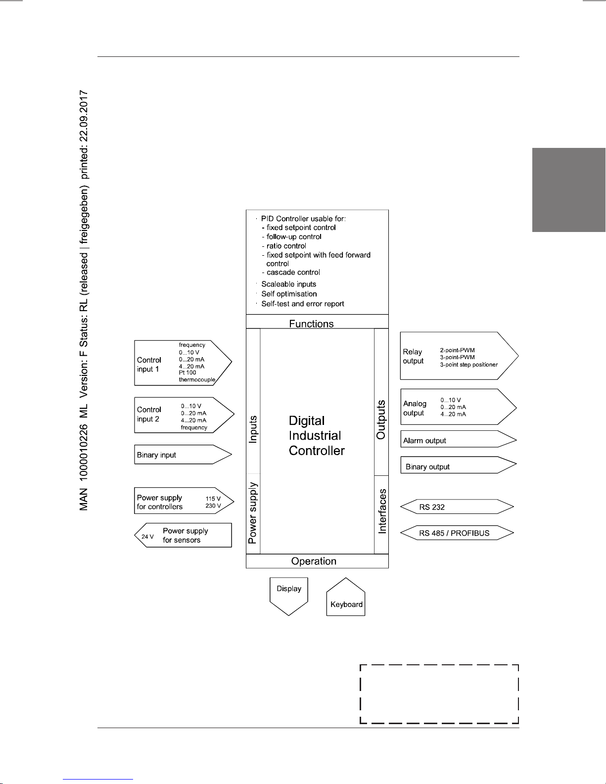
The digital industrial controller is designed as a PID controller for controlling tasks in
the process control technology. It represents a new controller generation based on a
microprocessor.
english
Either standard
scaleable controller inputs or resistance thermometers and thermocouples can be
connected.
Outputs for continuous standard signals or relay outputs can now be used as
controller outputs.
In addition, outputs for error reports and a binary input and output for additional
functions are available.
RS 232 or RS 485 / PROFIBUS serial interfaces are available as connection
options.
The following control tasks can be realised with the controller:
• Fixed setpoint control (single control loop)
• Fixed setpoint with feed forward control
• Follow-up control (external set-value)
• Ratio control
• Cascade control
The controller is characterised by user-friendly operation and has a backlit, easily
legible LCD plain language display.
The following operator actions can be carried out with menu support in various
operator control levels:
current/voltage
and frequency-analog signals can be applied to the
4 - 1110
• Configuration (defining the controller structure),
• Parameter definition (setting controller parameters),
• Process operation (manual interventions).
Configuration and parameter definition data is stored in an EEPROM to protect
against power failures.
NOTE
The digital industrial regulator complies with the 73/23/EWG
Low Voltage Regulations and the EMC 89/2338/EWG
Regulations.
Page 7
DIGITAL INDUSTRIAL CONTROLLER
Unauthorized operation of the individual operator control levels can be rendered
impossible by a free choice of user codes. Regardless of this, a permanently
programmed and invariable master code exists which allows access to all levels.
This 4-digit master code can be found on the bottom margin of this page. It
can be cut out and stored separately from the instruction manual.
Self-optimization algorithms (for self-adjustment and adaption) are implemented in
the controller and ensure automatic adaption of the controller’s parameters to the
process in the closed control loop.
Figure 1 shows an overview of the controller.
english
Figure 1: Overview diagram
✂
Mastercode for digital
industrial controller:
8575
1110 - 5
Page 8
DIGITAL INDUSTRIAL CONTROLLER
3 INSTALLING THE CONTROLLER
The controller was conceived for installation in switch panels. On the controller,
first of all remove the retaining elements engaged on both sides by swivelling in
anticlockwise direction. Insert the controller, including the enclosed rubber seal, into
the insertion opening from the front. Then again engage the two retaining elements
in the bolts on the sides of the housing and screw in the threaded pin inside from the
rear.
Switch panel insertion opening (W x H): 92 x 92 mm2 (+0,8 mm)
Outer controller dimensions (W x H x D): 96 x 96 x 173 mm
english
Controller weight: 960 g
Degree of protection: IP 65 (front when using the
Operating temperature: 0 bis +50 °C
Storage temperature: -20 bis +60 °C
ATTENTION!
4 CONNECTIONS
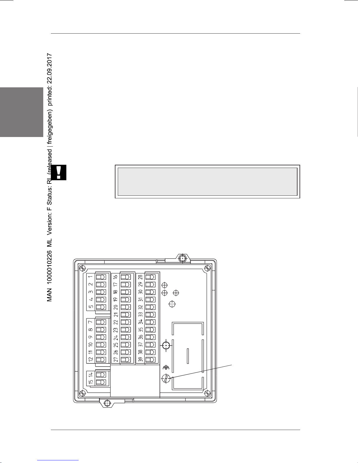
4.1 Pin assignments
3
enclosed seal)
To ensure the electromagnetic compatibility (EMC) the screw
terminal TE (Technical Earth) must be connected to the earth
potential by a cable that is as short as possible (30 cm, 2.5 mm2)
Figure 2: Rear side of controller
6 - 1110
TE connection
(Technical Earth)
Page 9

Relay 3
(Alarm)
Relay 3
(Alarm)
Relay 1
(Output)
DIGITAL INDUSTRIAL CONTROLLER
Controller input 2 Controller input 1
Position acknowledgement
Binary
output
Controller output
Standard signal
Current
Standard signal
Voltage
Relay 2
(Output)
Binary
input
Power
supply
Fig. 3: Allocation of the terminal strip
NOTE When connecting the sensor lines:
• Lay the lines separate from the power lines (lines in which large
currents flow) and high frequency lines. Never under any
circumstances use multi-pole cables to carry both power and
sensor lines.
• When using screened cables, only connect the screen at one
end. Never under any circumstances connect the screen to both
the protective conductor and the earth of the regulator input.
Resistance
thermometer
PT100
Thermo
couples
english
4.2 Supply voltages
Power supply for the Connect to terminals 14
controller: and 15.
Model 1: 115 / 230V 50 ... 60 Hz
Model 2: 12 / 24V 50 ... 60 Hz
Power supply for 24 V DC Accessible on terminals 23
transducers: and 24.
ATTENTION!
To ensure the electro-magnetic compatibility (EMC), the screw
terminal TE (Technical Earth) must be connected to the earth
potential with a short cable (30 cm, 2.5 mm2).
1110 - 7
Page 10
DIGITAL INDUSTRIAL CONTROLLER
4.2.1 115/230 V and 24/48 V Changeover
By means of a jumper inside the unit, the supply voltage can be changed from 230 V
to 115 V, or from 12 V to 24 V respectively. This adaptation must take place before
installing the unit.
Procedure:
Î Insert all connection and supply lines
Î Remove the connecting screw for the Technical Earth
english
Î Remove the optionally-installed interface card (if present)
Î Undo the four screws on the rear plate, and remove the rear plate
Î Pull the unit one third of the way out of the housing
Î The jumper is easily accessible on the power supply printed-circuit board,
positioned immediately in front of one of the relays and identified by the numbers
1-4 on the board.
Î At delivery, the connector is positioned between contacts 2 and 4
Î To change the unit to 115V or 12 V respectively, contacts 1 and 3 must be
bridged with the connector. Proceed identically when changing from 24V to 12V.
Î Finally, push the unit back into the housing, and screw on the rear plate.
NOTE
If the unit is to be set to the lower voltage, please ensure that the
voltage does not exceed the quoted tolerances, and make a note
on the wiring diagram.
4.2.2 24V DC/AC Converter for operation at 24 V DC
The 12/24V AC controller model can also be operated at 24 VDC using an optional
DC/AC converter. Up to 3 controllers can be supplied from a single converter. (Order
number: 19139J)
Supply voltage 16V - 26V DC
Output voltage 16V-26V AC (50 Hz)
Efficiency > 95%
Switch-on delay max. 5 secs
Dimensions (WxHxD) 23 x 75 x 110 mm
8 - 1110
3
Page 11
4.3 Signal inputs
All signal inputs are short-circuit proof, are voltage-stable to 41 volts and are
galvanically isolated with regard to the outputs and the supply voltage.
Controller input 1:
The following input configurations are available:
• Input for standard signal (voltage) 0 ... 10 V Terminals 30 and 31
Input resistance: > 400 kΩ
Measuring error: < 0,2 %
Temperature influence: < 0.2 % / 10 degrees
• Input for standard signal (current) 0 (4) ... 20 mA Terminals 29 and 31
Input resistance: < 300 Ω in accordance with DIN IEC 381 (typically 200)
DIGITAL INDUSTRIAL CONTROLLER
english
Measuring error: < 0,2 %
Temperature influence: < 0.2 % / 10 degrees
Nominal temperature: 22 °C
Wire breakage and short-circuit detection within the range from 4 to 20 mA
• Input for frequency-analog signal 5 ... 1000 Hz Terminals 28 and 31
Input resistance: > 10 kΩ
Measuring error: < 0,1 %
Signal types: Sine wave, square wave, delta ( > 300 mVpp)
• Input for connection of Pt 100 resistance Terminals 35, 36, 37, 38
thermometers
(in accordance with DIN 43760 for 3 and 4-wire connection)
Measurement range - 200 to + 850 °C
Measurement current max. 0,5 mA
Measuring error ± 0.2 % ± 2 digits
1110 - 9
Page 12
DIGITAL INDUSTRIAL CONTROLLER
english
NOTE
• Input for connection of thermocouples Terminals 38 and 39
For the following thermocouples, the characteristics are linearised internally:
Type Thermocouple pair Measurement range Accuracy
J Fe - CuNi -200 to +1200 °C < ± 0.3 % ± 1 Digit
K NiCr - Ni -200 to +1370 °C < ± 0.3 % ± 1 Digit
T Cu - CnNi 0 to +400 °C < ± 0.3 % ± 2 Digit
R Pt 13Rh - Pt 0 to 1760 °C < ± 0.3 % ± 1 Digit
S Pt 10Rh - Pt 0 to 1760 °C < ± 0.3 % ± 1 Digit
NOTE
If the displayed values are fluctuating, set the limit frequency of the
digital filter to a lower value in the Inputs menu and check the TE
connection.
If the displayed values are fluctuating, set the limit frequency of the
digital filter to a lower value in the Inputs menu and check the TE
connection.
Input impedance: > 1 MΩ
Comparison point compensation:
• internal with integrated NTC thermistor
Comparison point compensation error: 0.5 K ± 1 digit
• external with Pt 100 resistance thermometer
Controller input 2
• Input for standard signal (voltage) 0 ... 10 V Terminals 18 and 19
(same technical data as for controller input 1)
• Input for standard signal (current) 0 (4) ... 20 mA Terminals 17 and 19
(same technical data as for controller input 1)
• Input for frequency-analog signal 5 ... 1000 Hz Terminals 16 and 19
(same technical data as for controller input 1)
Configurable for:
• Feed forward control
• Follow-up control (external setpoint)
• Ratio control
• Cascade control
10 - 1110
Page 13

DIGITAL INDUSTRIAL CONTROLLER
• Input for the connection of a potentiometer Terminals 19, 20 and 27
for position feedback (1 ... 10 kΩ)
for position regulation
• Binary inputs Terminals 25 and 26
Input resistance: > 25 kΩ
Configurable line of action:
Logical value Voltage not inverted inverted
0 0 ... 4,5 V nactive active
1 13 ... 35 V active inactive
Configurable functions:
• Changeover between manual and automatic mode
• Changeover between external and internal setpoint *)
• Triggering alarms
• Safety value output
*) Available only if controller input 2 has been configured for an external setpoint.
english
4.4 Signal outputs
Controller output
The following output configurations are available:
Controller output for continuous signals
• Output for standard signal 0 ... 10 V Terminals 33 and 34
max. load current: 5 mA
Accuracy: 0,5 %
• Output for standard signal 0 (4) ... 20 mA Terminals 32 and 33
max. load resistance: 600 Ω
Accuracy: 0,5 %
Controller outputs for discontinuous signals
2 relays with one potential free changeover contact each:
Relay 1 Terminals 7, 8 and 9
Relay 2 Terminals 10, 11 and 12
1110 - 11
Page 14
DIGITAL INDUSTRIAL CONTROLLER
The following output signals are configurable (cf. Sections 5.7 and 6.5.4):
• 2-point PWM signal (PWM: Pulse width modulation)
• 3-point PWM signal
• 3-point step signal
• 3-point step signal with external feedback (position control)
Electrical data of the relay AC DC
Max. switched voltage 250 V 300 V
Max. switched current 5A 5A
english
Max. switched power 1250 VA 100 W at 24V, 30 W at 250V
• Binary output Terminals 21 and 22
max. load current: 20 mA
Configurable line of action (not inverted / inverted):
Logical value Output not inverted inverted
0 high resistance inactive active
1 17.5 ... 24 V active inactive
Configurable functions:
• Signal:
• Signal:
• Signal:
Outputs for alarms
2 relays with one potential free changeover contact and internal connected bose
(see connection diagram):
Relay 3 Terminals 1, 2 and 3
Relay 4 Terminals 3, 4 and 5
Configurable alarms:
• Alarm, absolute
• Alarm, relative
• Alarm, ratio
Alarm has occurred
Error has occurred
MANUALmode
Electrical data of the relay AC DC
Max. switched voltage 250 V 300 V
Max. switched current 5A 5A
Max. switched power 1250 VA 100 W at 24V, 30 W at 250V
12 - 1110
Page 15
DIGITAL INDUSTRIAL CONTROLLER
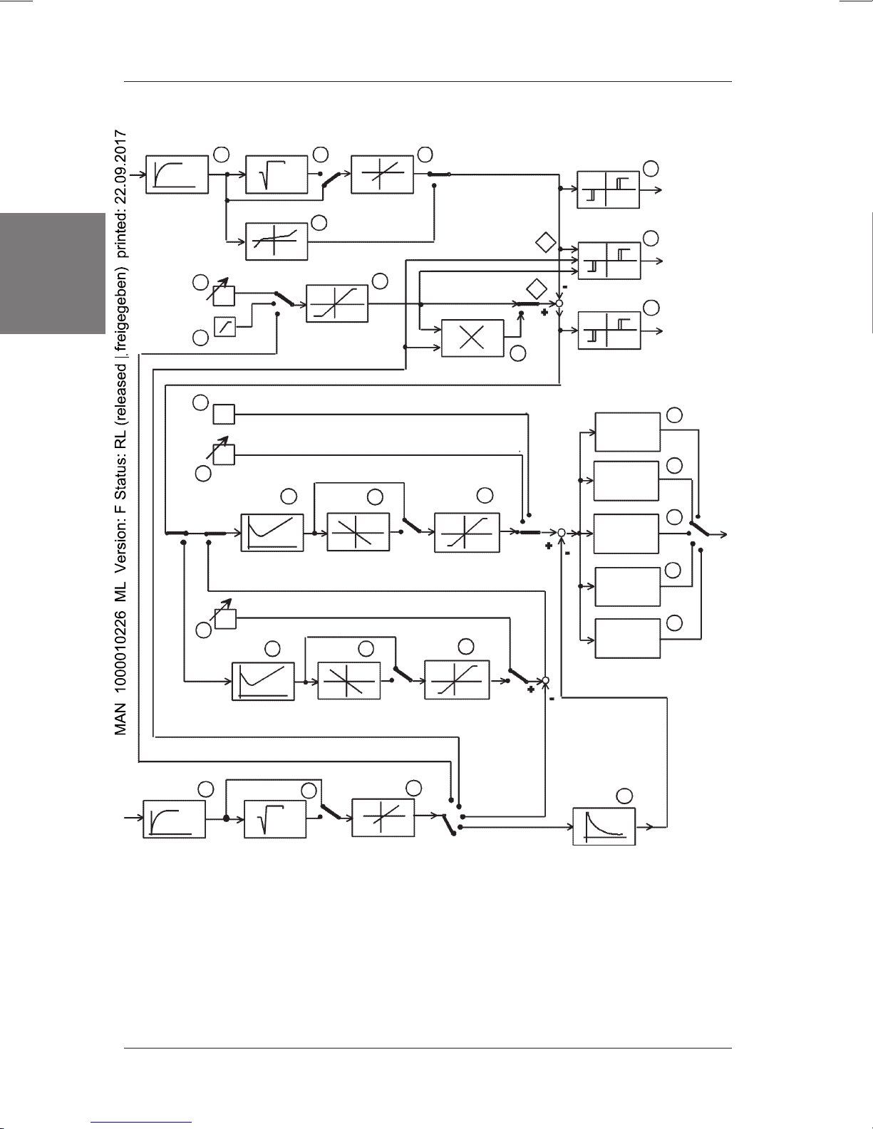
5 CONTROLLER STRUCTURES
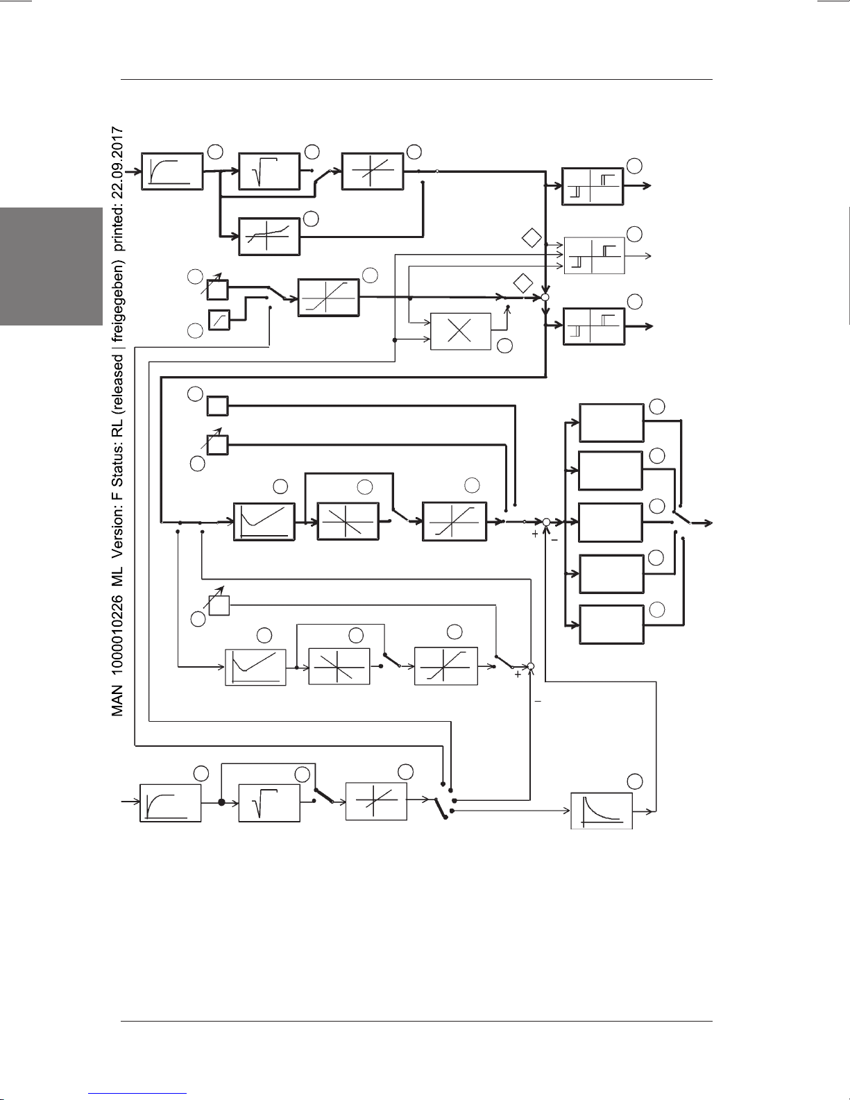
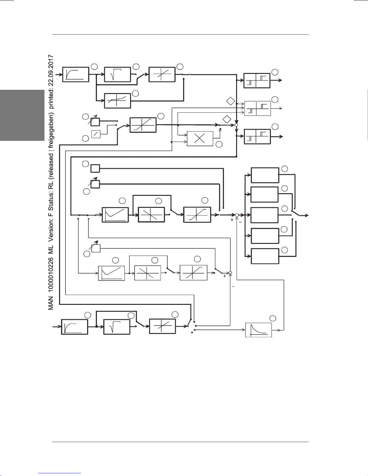
5.1 Overall Structure of the Digital Industrial Controller
Figure 4 shows the overall structure of the digital industrial controller in the form of a
signal flow chart. In addition to function blocks, it contains function selectors which
are used to set a concrete controller structure when configuring the controller.
The following concrete controller structures can be configured on the basis of the
overall structure:
• Controller for single control loop
(
Standard controller
• Controller with additional functions for feed forward control
(
Feed forward controller
• Controller with additional functions for follow-up control
(
External setpoint controller
• Controller with additional functions for ratio control
(
Ratio controller
• Controller with additional functions for cascade control
(
Cascade controller
The function blocks contained in the overall structure are explained in Section 5.7.
structure)
structure)
structure)
structure)
structure)
english
1110 - 13
Page 16
DIGITAL INDUSTRIAL CONTROLLER
Filter 1
PV1
Input 1
english
Ramp
13
5
6
14
Root extraction Scaling
1
Linearisation
SP1
23
4
Setpoint
limiting
COs
CO
10
Controller 2
7
11
Line of action
Multiplier
CO2
Manipulated
variable limiting
12
27
SP
PV1
Alarm abs.
Alarm ratio
Alarm rel.
Continuous
signal
2-pointPWM signal
3-pointPWM signal
3-pointstep signal
8
Aabs
28
Averh
9
Arel
15
16
17
RA
18
SP2
22
20
29
21
CO1
Controller 1
Input 2
23 24
PV2
Filter 2 Root extraction
Line of action
Scaling
Manipulated
variable limiting
25
ext.SP
off
ratio
cascade
Feed forward
Figure 4: Overall structure of the Digital Industrial Regulator
Refer to Page 122 ff for a description of the function blocks
3-point-step
signal with
ext. p. a.
26
PDT1
Feed forward
control
19
Controller
output
14 - 1110
Page 17
DIGITAL INDUSTRIAL CONTROLLER
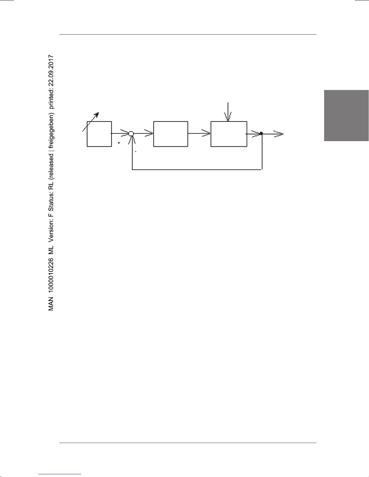
5.2 Controller for single control loop
5.2.1 Single control loop
If a control task consists of keeping a quantity (e.g. a temperature) at a fixed setpoint
SP (constant), a fixed setpoint control configuration is used for this purpose. The
control variable PV (temperature) is measured and compared against the setpoint
SP (Figure 5).
Z
Setpoint
generator
SP
PVd
F
R
Controller
CO
Controlled system
PV
F
S
Figure 5: Single control loop
If it deviates from the setpoint as the result of a disturbance Z, for example, the
controller generates a manipulated variable CO according to this deviation, which is
referred to as the system deviation PVd = SP-PV, in such a way that the controlled
variable PV is adapted as exactly as possible to the setpoint.
A PID controller can be used for this purpose. With regard to its parameters, it must
be configured so as to arrive at a control response that does justice to the task in
hand (see Annex).
Example:
Let us look at control of a room’s temperature as an example of a fixed setpoint
control configuration in a single control loop. The aim is to compensate all
disturbances that cause the room temperature to deviate from the temperature
setpoint. The room temperature is compared against the setpoint SP. According to
the system deviation PVd, the controller adjusts the fuel supply until the required
room temperature has been reached.
english
5.2.2
Standard controller
The
standard controller
overall structure appropriately. It is based on PID controller 2. PID controller 1 is not
used. Input 1 is used for the controlled variable PV1, while input 2 is not used. SP1
is the setpoint that has to be set.
structure
structure shown in Figure 6 is obtained by configuring the
1110 - 15
Page 18
DIGITAL INDUSTRIAL CONTROLLER
Filter 1
PV1
Input 1
english
5
Ramp
6
13
14
Root extraction Scaling
213
Linearisation
SP1
4
Setpoint
limiting
COs
CO
10
Controller 2
7
11
Line of action
CO2
Multiplier
12
Manipulated
variable limiting
8
Aabs
Alarm abs.
PV1
28
Averh
SP
27
Alarm ratio
Alarm rel.
Continuous
signal
2-pointPWM signal
3-pointPWM signal
3-pointstep signal
9
Arel
15
16
17
RA
18
SP2
22
20
29
CO1
Controller 1
Line of action
Manipulated
variable limiting
Input 2
PV2
Filter 2
23
Root extraction
24
Scaling
25
ext.SP
off
Figure 6: Structure of the Standard Controller
Description of the functional blocks from Page 122
21
ratio
cascade
Feed forward
3-point-step
signal with
ext. p. a.
PDT1
Feed forward
control
19
Controller
output
26
16 - 1110
Page 19
DIGITAL INDUSTRIAL CONTROLLER
5.3 Controller with additional functions for feed forward control
5.3.1 Single control loop with feed forward control
The control response of a single control loop can be improved substantially in most
cases by feed forward control. The precondition for this is that the disturbance
variable can be measured and recorded.
The disturbance can be fed either to the controller's input or output via a
compensator Fk (Fig. 7). In the digital controller, the disturbance is fed forward to the
controller's output. The compensator Fk consists of a PDT-1 element. This element's
P component feeds forward in proportion to the disturbance. The D component feeds
a value that is proportional to changes in the disturbance. Both components can be
chosen freely when configuring or defining the parameters.
english
Z
F
Z
PV
F
S2
Partial controlled
system 2
Setpoint
generator
SP PVd
F
R
Controller
Compensation element
F
K
CO
F
S1
Partial controlled
system 1
Figure 7: Single control loop with feed forward control
a) to the controller’s input
b) to the controller’s output
Example:
Let us take water level control in a steam boiler as an example of fixed setpoint
control with feed forward control. The water level is measured and controlled by way
of the supply of feed water. Here, the outgoing quantity of steam manifests itself in
the form of the principal disturbance. If it is measured and additionally fed forward to
the controller. The controller's response can be improved in this way.
5.3.2
Feed forward controller
The
feed forward
configuring the overall structure accordingly. It is based on PID controller 2.
PID controller 1 is not used. Input 1 is used for the controlled variable PV1, while
input 2 serves to feed the disturbance forward to the controller’s output. SP1 is the
setpoint that has to be set.
structure
controller structure highlighted in Figure 8 is obtained by
1110 - 17
Page 20
DIGITAL INDUSTRIAL CONTROLLER
Filter 1
PV1
Input 1
english
Ramp
Root extraction
1
Linearisation
5
SP1
6
4
Setpoint
limiting
13
COs
CO
14
10
Controller 2
Scaling
2
11
Line of action
3
8
Aabs
Alarm abs.
PV1
7
Multiplier
12
CO2
SP
27
Alarm ratio
Alarm rel.
Continuous
signal
2-pointPWM signal
3-pointPWM signal
Manipulated
variable limiting
3-pointstep signal
28
Averh
9
Arel
15
16
17
RA
18
SP2
22
20
29
CO1
Controller 1
Line of action
Manipulated
variable limiting
Input 2
PV2
23
Filter 2 Root extraction
24
Scaling
25
ext.SP
off
Figure 8: Structure of the feed forward control
Description of the functional blocks from Page 122
21
ratio
cascade
Feed forward
3-point-step
signal with
ext. p. a.
PDT1
Feed forward
control
19
Controller
output
26
18 - 1110
Page 21

DIGITAL INDUSTRIAL CONTROLLER
5.4 Controller with additional functions for follow-up control
5.4.1 Follow-up control (external set-point input)
The purpose of a follow-up control is to slave the controlled variable PV1 as exactly
as possible to another variable, the command variable, which varies in time. Either a
process variable PV2 originating from a system FS2 or a different variable with a
given time progression can be used as the command variable (Figure 9).
Z
SP=
PV2
F
S2
PVd
CO
F
R
F
S
PV1
english
5.4.2
Setpoint
generator
Controller
Controlled system
Figure 9: Follow-up control
The controller of a follow-up control configuration must be designed so as to arrive
at a good response to setpoint changes with a short settling time and wellattenuated stabilisation.
Example:
Let us take a power steering system as an example of a follow-up control. The
command variable PV2 for the angle of the wheel (controlled variable PV1) is
specified by the position of the steering wheel.
External setpoint controller
The
external setpoint
controller structure highlighted in Figure 10 is obtained by
structure
appropriately configuring the overall structure. It is based on PID controller 2. PID
controller 1 is not used. Input 1 is used for the control variable PV1, while the
command variable is applied to input 2 as the external setpoint.
In this controller structure, the binary input can be used to switch between the
external setpoint and the setpoint SP1.
1110 - 19
Page 22
DIGITAL INDUSTRIAL CONTROLLER
Filter 1
PV1
Input 1
english
5
Ramp
6
13
14
22
Root extraction
SP1
COs
CO
Controller 2
SP2
Linearisation
10
20
Scaling
213
4
7
SP
Alarm abs.
PV1
Alarm ratio
Setpoint
limiting
Line of action
Multiplier
11
CO2
Manipulated
variable limiting
29
21
27
Alarm rel.
Continuous
signal
2-point-
12
PWM signal
3-pointPWM signal
3-pointstep signal
3-point-step
signal with
ext. p. a.
8
Aabs
28
Averh
9
Arel
15
16
17
RA
18
19
Controller
output
CO1
Controller 1
Input 2
PV2
23
Filter 2 Root extraction
Line of action
24
Scaling
Manipulated
variable limiting
25
ext.SP
off
Figure 10: Structure for External Set-Point
Description of the functional blocks from Page 122
20 - 1110
ratio
cascade
Feed forward
26
PDT1
Feed forward
control
Page 23
DIGITAL INDUSTRIAL CONTROLLER
5.5 Controller with additional functions for ratio control
5.5.1 Ratio control
A ratio control is a special type of follow-up control and/or external set-point input.
The task of a ratio control is to cause a controlled variable (PV1) to track another
process variable (PV2) within a specific ratio.
PV1 is described as the dependent variable, and PV2 as the command variable.
In the regulated condition of the ratio control, the following equation applies:
SPr = PV1 / PV2
SPr: ratio set-point
PV1: dependent variable (controlled variable)
PV2: command variable
This gives the internal set-point for the channel X1 that is to be controlled:
PV1set = PV2*SPr
SP = X2*SPr
Controller
Ratio
setpoint
SPr
Command
variable
PV2
Multiplier
Setpoint
SP
Reference
system
PID Controller
PV1
Regulated
variable CO
english
Controlled system
Figure 11: Ratio control
Example:
Let us take mixture control of an acid/alkali flow as an example of a ratio control
system. The internal setpoint SP for the supply of acid (PV1 set) is generated by
multiplying the flow rate of the alkali (command variable PV2) with the ratio setpoint
SPr.
Follow-up
system
1110 - 21
Page 24
DIGITAL INDUSTRIAL CONTROLLER
5.5.2
Ratio controller
Filter 1
PV1
Input 1
english
structure
The
ratio controller
configuring the overall structure. It is based on PID controller 2. PID controller 1 is
not used. Input 1 is used for the control variable PV1 and the process variable PV2
is applied to input 2. SP1 is the ratio setpoint that has to be set.
Root extraction
13
Linearisation
5
SP1
Ramp
6
13
COs
CO
14
Controller 2
structure highlighted in Figure 12 is obtained by appropriately
2
4
Setpoint
limiting
Scaling
7
1110
Line of action
CO2
Multiplier
12
Manipulated
variable limiting
8
Aabs
Alarm abs.
PV1
28
Averh
SP
27
Alarm ratio
Alarm rel.
Continuous
signal
2-pointPWM signal
3-pointPWM signal
3-pointstep signal
9
Arel
15
16
17
18
RA
SP2
22
20
29
21
CO1
Controller 1
Line of action
Manipulated
variable limiting
Input 2
PV2
Filter 2
23
Root extraction
24
Scaling
25
ext.SP
ratio
Figure 12: Ratio controller structure
See Page 25 ff for a description of the function blocks
22 - 1110
cascade
Feed forwardoff
3-point-step
signal with
ext. p. a.
PDT1
Feed forward
control
19
Controller
output
26
Page 25
DIGITAL INDUSTRIAL CONTROLLER
5.6 Controller with additional functions for cascade control
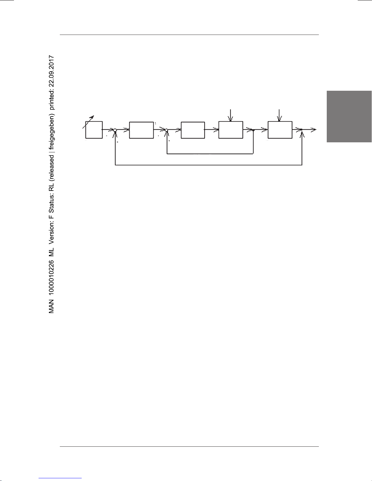
5.6.1 Cascade control
In a cascade control, two control loops are interlinked so that one control loop (the
main control loop) is superimposed on the other (the auxiliary control loop). We
therefore speak of a double control loop (Figure 13).
Z1Z2
CO2
R1
Subsystem 2
Auxiliary control loop
PV2
F
S2
F
R1
Subsystem 1
PV1
Setpoint
generator
SP1
PVd 1
Main controller
CO1
F
R1
Main control loop
PVd2
F
Auxiliary
controller
Figure 13: Cascade control
The controlled system is split into the two subsystems FS1 and FS2. The controlled
variable PV1 is measured on the subsystem FS1 and the auxiliary controlled variable
PV2 is measured on the subsystem FS2.
The auxiliary control loop consists of the auxiliary controller FR2 and the subsystem
FS2. The setpoint for the auxiliary control loop is given by the output variable CO1 of
the main controller FR1, which constitutes the main control loop together with the
auxiliary control loop and the subsystem FS1. The setpoint of the main control loop is
specified as SP1.
A prerequisite for interaction between the two control loops is that the auxiliary
control loop must have a faster time response than the main control loop, i.e. the
essential delays are encountered in the sub-loop FS1. Disturbances Z2 influencing
the subsystem FS2 are balanced out by the faster auxiliary control loop and
disturbances Z1 influencing the subsystem FS1 are balanced out by the main control
loop.
english
Example:
Control of the temperature in a tank heated with hot steam can be mentioned as an
example of a cascade control. A fast auxiliary control loop for control of the
hot steam flow rate is superimposed on the slow temperature control loop with the
main controller FR1.
1110 - 23
Page 26

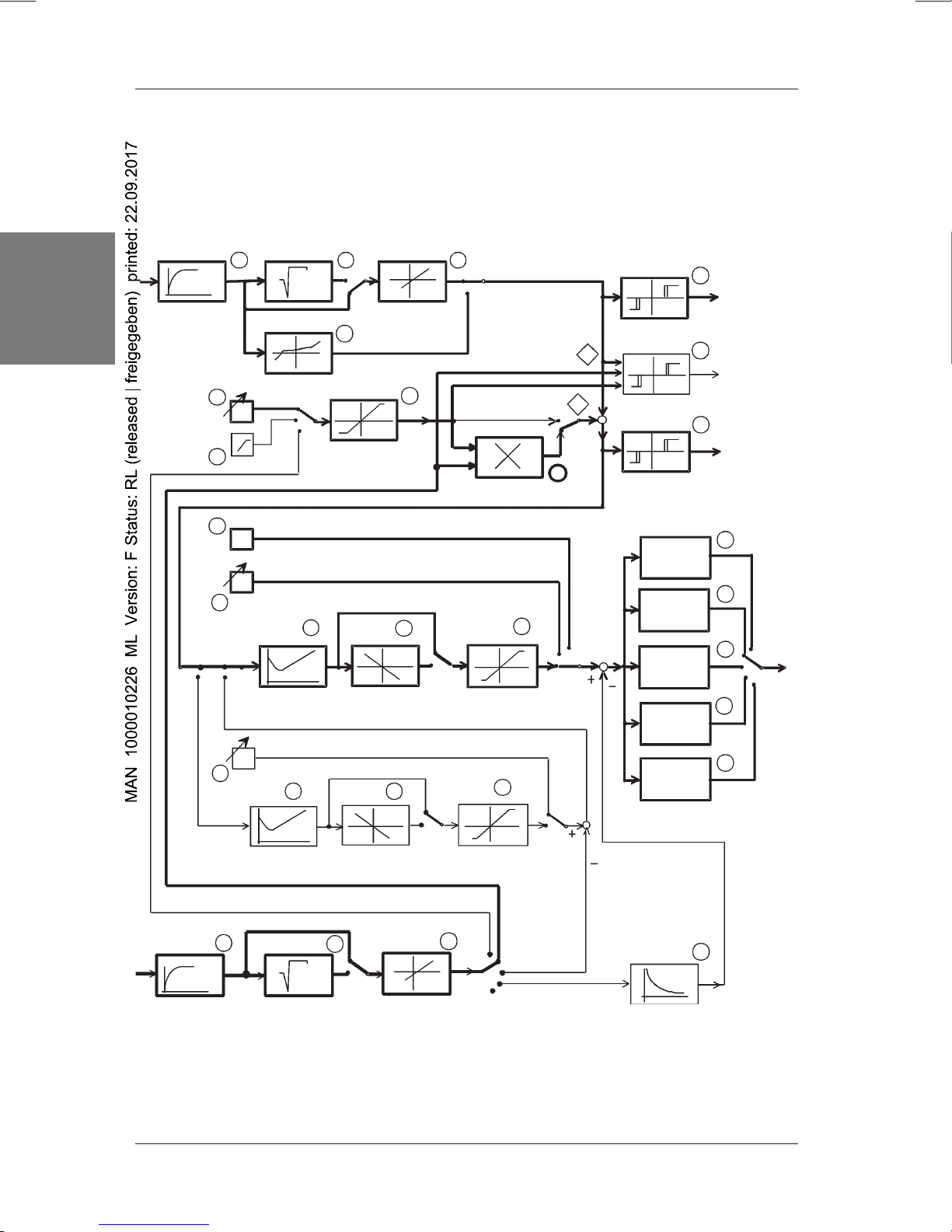
DIGITAL INDUSTRIAL CONTROLLER
5.6.2
english
Cascade controller
The
cascade controller
appropriately configuring the overall structure.
PID controller 1 is used as the main controller and PID controller 2 as the auxiliary
controller. Input 1 is used for the controlled variable PV1 of the main control loop and
input 2 is used for the auxiliary controlled variable PV2.
SP1 is the setpoint for the main control loop. When the main controller is in AUTO
mode, it specifies the setpoint for the auxiliary control loop. When the main controller
is in MANUAL mode, a setpoint SP2 for the auxiliary control loop can be set on the
keyboard.
structure
structure highlighted in Figure 14 is obtained by
24 - 1110
Page 27
DIGITAL INDUSTRIAL CONTROLLER
PV1
Filter 1
Input 1
5
Ramp
6
13
14
Root extraction Scaling
Linearisation
SP1
213
4
Setpoint
limiting
COs
CO
10
Controller 2
7
11
Line of action
CO2
Multiplier
12
Manipulated
variable limiting
8
Aabs
Alarm abs.
PV1
28
Averh
-
SP
+
27
Alarm ratio
Alarm rel.
Continuous
signal
2-pointPWM signal
3-pointPWM signal
3-pointstep signal
9
Arel
english
15
16
17
RA
18
SP2
22
20
29
21
CO1
Controller 1
Line of action
Manipulated
variable limiting
Input 2
PV2
Filter 2
2423
Root extraction
Scaling
25
ext.SP
off
ratio
cascade
Feed forward
Figure 14: Cascade controller structure
See Page 122 ff for a description of the function blocks.
3-point-step
signal with
ext. p. a.
PDT1
Feed forward
control
19
Controller
output
26
1110 - 25
Page 28
DIGITAL INDUSTRIAL CONTROLLER
5.7 Explanations of the controller structures' function blocks
Functional Block 1: Filter at Input 1
Using the filter, the disturbance signals superimposed on the measured signal can
be damped. The filter is designed as a 1st order low-pass filter.
The limiting frequency of the filter can be set up within the range 0.1 to 20.0 Hz via
the parameters Fg1 (1st input) and Fg2 (2nd input) in Parameter (Filter menu) and
Configure (Input 1 and Input 2 menus).
english
• 0.1 Hz (strong damping, time constant 1.6 seconds)
• 20.0 Hz (weak damping, time constant 0.01 seconds)
ATTENTION!
Adjustable parameters:
Fg1: Limiting frequency (- 3 dB) of the filter at input 1.
Function block 2: Root extraction at input 1
This function serves to extract the square root of the input signal. It is needed
whenever the flow rate is measured as a pressure difference on a nozzle or
diaphragm (effective pressure method).
As, in some cases, the filter constant can have an effect on the
regulation parameters, the settings of the limiting frequency of
the filter should always be carried out before setting the
regulation parameters.
Function block 3: Scaling at input 1
Scaling assigns a numeric value to the measured electrical value that corresponds
to the physical measured quantity (Figure 15).
Adjustable parameters:
PVh: High scaling value, which is assigned to the maximum current,
voltage or frequency value.
PVl: Low scaling value, which is assigned to the minimum current,
voltage or frequency value.
26 - 1110
Page 29
Scaling value
PVh
DIGITAL INDUSTRIAL CONTROLLER
PVl
0
Fmin (0 Hz)
4 mA
20 mA
10 V
Fmax
Standard signal
Frequency-analog signal
Figure 15: Scaling
Function block 4: Linearisation
The characteristics of the various thermocouples and of the Pt 100 are linearised
internally.
Function block 5: Setting the setpoint SP1
Setting the set point using the regulator keyboard
Function block 6: Ramp
english
The set point can be continually increased or decreased using the ramp function.
Options:
Ramp on: Setpoint ramp active. An entered setpoint is initialised by way of the
Ramp off: Setpoint ramp not active.
ramp.
In a cascade control, the setpoint ramp is only available for the main
controller. The ramp is only started when the controller is in
Automatic mode.
1110 - 27
Page 30
DIGITAL INDUSTRIAL CONTROLLER
Adjustable parameters:
D: Pitch of the setpoint ramp
SP
english
∆SP
∆t
Figure 16: Ramp function
Function block 7: Setpoint limiting
A low and a high limit can be entered for the setpoint. The setpoint can only be
adjusted within this range.
Adjustable parameters:
SPh: High setpoint limit
SPl: Low setpoint limit
D=∆SP / ∆t
t
Function block 8: Alarm, absolute
With this function, the alarm relay is operated if the controlled variable PV exceeds
an upper limit or falls below a lower limit. The limits can be adjusted within the
scaling range PVl .. PVh, or within the measurement range of the temperature
inputs.
High limit violation: Alarm via relay 3
Low limit violation: Alarm via relay 4
Adjustable parameters:
PV+ : High alarm limit
PV- : Low alarm limit
Hy : Switching hysteresis
28 - 1110
Page 31

DIGITAL INDUSTRIAL CONTROLLER
Function block 9: Alarm, relative
This function actuates the alarm relays when the system deviation exceeds a high
limit or falls below a low limit. In this case, therefore, the limits are referred to the
setpoint (relative). This alarm function is not available when ratio control is
configured.
High limit violation: Alarm via relay 3
Low limit violation: Alarm via relay 4
Adjustable parameters:
PV+ : High alarm limit
PV- : Low alarm limit
Hy : Switching hysteresis
Function block 10: PID controller (2)
This function block is a parameter-definable PID controller that can be used either
as a single controller or as an auxiliary controller within the scope of cascade
control.
english
Adjustable parameters:
Kp: Amplification factor
Tr: Reset time
Td: Derivative action time
CO0: Operating point
Function block 11: Line of action
Here, a function selector can be used to set whether the actuator is to be triggered
with a positive or negative line of action. When a positive line of action is set, the
output signal CO of PID controller 2 increases along with rises in the system
deviation PVd, while it decreases when the line of action is negative.
Options:
Inv. no: positive line of action
Inv. yes:negative line of action
1110 - 29
Page 32

DIGITAL INDUSTRIAL CONTROLLER
Y
CO
Positive line of action
positiver Wirkungssinn
negativer Wirkungssinn
Negative line of action
english
0
xd (Regeldifferenz)
PVd (system deviation)
Figure 17: Line of action with reference to the P controller
Functional block 12: Setting the regulated variables
This function block can be used to define the range within which the controlled
variable CO may vary.
Adjustable parameters:
COh: Maximum value of the controlled variable
COl: Minimum value of the controlled variable
For 3-point PWM signals, the heating / cooling range can be limited separately. If the
variable is at a limit value, the integrator circuit will be active.
Chh: Maximum value of the heating variable (Relay 1)
Chl: Minimum value of the heating variable (Relay 1)
Cch: Maximum value of the cooling variable (Relay 2)
Ccl: Minimum value of the cooling variable (Relay 2)
For a 3-point step output without external feedback, the variable limitation is not
available.
Function block 13: Safety value
Here, you specify the controlled variable that is to be output in the event of a
malfunction occurring or if the binary input is activated (when the „Output safety
value“ function is configured; see Section 6.5.4)
Adjustable parameters:
COs: Safety value of the control variable
30 - 1110
Page 33

DIGITAL INDUSTRIAL CONTROLLER
Function block 14: Manual controlled variable adjustment
This functional block can be activated at the Process Operation level. The manual
variable setting is only possible in the MANUAL operating mode of the unit. The
control element is switched out by the controller, and driven with the last-calculated
set variable. The value can now be changed using the “arrow” keys (See Par. 6.3).
Function block 15: Continuous signal
The controlled variable CO is output as a continuous signal Ra (see Figure 6, for
example). Three standard signals can be selected:
• Standard signal 0...10 V
• Standard signal 0...20 mA
• Standard signal 4...20 mA
Function block 16: 2-point PWM signal
2-point output
english
When using a switching output, such as the 2-point PWM output, the continuous
variable CO, which is calculated by the PID algorithm, must be converted into a
switching signal.
This conversion takes place via a PWM element (PWM: Pulse-Width Modulation).
The relay will be clocked with a changeover period which is proportional to CO. In
this way, a quasi-continuous behaviour is achieved. The period T+ of the PWM
signal must be adapted to the regulated system.
Ra
ton
Relay on
Relay off
0
toff
ton / T+ ~ CO
t
T+
Figure 18: 2-point PWM signal
CO = ton / T+ *100%
ton = CO / 100 % T+
1110 - 31
Page 34

DIGITAL INDUSTRIAL CONTROLLER
Adjustable parameter:
T+: Period of the 2-point PWM signal
Options:
Imp. no: Use of a standard valve.
The 2-point PWM signal is output via relay1
Imp. yes: Use of a pulse valve. 2 relays are used for output in this case.
Relay 1 is energised with the rising edge of the 2-point PWM signal,
english
Function block 17: 3-point PWM signal
3-point Output
while relay 2 is energised with its falling edge. A pulse valve can be
actuated in this way. The valve’s pick-up winding is triggered with
relay 1, while its drop-out winding is triggered with relay 2.
The 3-point PWM output is a combination of two 2-point PWM outputs. One PWM
output controls the output relay 1 (Output relay, heat) dependent on COh, while the
other PWM output controls the output relay 2 (Output, cool) dependent on COk.
Each of the two outputs is subordinated to a PID algorithm within the controller. The
following diagram shows the principle of the controller characteristic for the 3-point
output:
Controlled
100 %
Setpoint SP Actual value PV
variable CO
HeatCool
Characteristic for
P-controller
Figure 19: 3-point output
The Output, Heat period, T+, and the Output, Cool period, T-, can be set separately
of one another.
In addition, the amplification factors for both controllers (heat / cool) can be
separately adjusted. The reset time Tr (I-portion of the controller) and the derivative
action time Td (D-portion of the controller) are the same for both controllers.
32 - 1110
Page 35

DIGITAL INDUSTRIAL CONTROLLER
Overlap area
When using the 3-point PWM Output, the following controller behaviour results in
the area around the set-point, depending on the setting of the overlap area:
Overlap area negative
(Dead range)
Controlled
100 %
Setpoint SP
variable CO
HeatCool
OLP < 0
Characteristic
for P-controller
Actual value PV
Overlap area positive
(overlap)
Figure 20: Overlap area for 3-point PWM signal
Adjustable parameters:
T+: Period for switching relay 1 (heating)
T- : Period for switching relay 2 (cooling)
Olp: Overlap zone (heating and cooling)
100 %
Setpoint SP
OLP > 0
Controlled
variable CO
HeatCool
english
Characteristic
for P-controller
Actual value PV
Funktionsblock 18: 3-Punkt-Schritt-Signal
The 3-point step signal can be used to control motor-driven actuators. In doing so,
TCO is the time needed to move the actuator from one end position to the other.
Adjustable parameters:
Gt: Backlash of the gearbox when shifting from forwards to reverse
Psd: insensitive area (for explanation, refer to Chapter 6.5.4)
TCO: Regulating time (motor running time)
1110 - 33
Page 36

DIGITAL INDUSTRIAL CONTROLLER
Function block 19: 3-point step signal with external position
acknowledgement (Position control)
This signal serves to control motor-driven actuators on which a position
acknowledgement is provided by way of a potentiometer. The resistance value of the
acknowledgement potentiometer must be within the range from 1 kΩ to 10 kΩ.
Adjustable parameters:
Psh: Switching hysteresis
Psd: Insensitivity zone
english
Relay output
SP
PV
Psh
Psd
Figure 21: 3-point step signal
Function block 20: PID controller 1
This function block is a parameter-definable PID controller that is used as a main
controller for cascade control.
Adjustable parameters:
Kp: Proportional action coefficient / Gain
Tr: Reset time
Td: Derivative action time
Pdb: Dead area
CO0: Operating point
34 - 1110
Page 37

DIGITAL INDUSTRIAL CONTROLLER
Function block 21: Manipulated variable limiting
This function block can be used to define the range in which the output variable of
controller 1 may vary.
Adjustable parameters:
COh: Maximum value of the output variable
COl: Minimum value of the output variable
Function block 22: Setting the setpoint SP2
Setting the set-point via the controller keyboard (set-point of the subordinate
controller for cascade regulation).
Function block 23: Filter at input 2
The filter can be used to attenuate interference signals superimposed on the
measured signal. The filter consists of a low pass filter of the first order (see
Functional Block 1).
Adjustable parameters:
Fg2: Limiting frequency (- 3 dB) of the filter at input 2.
Function block 24: Root extraction at input 2
This function serves to extract the root of the measured signal at input 2 (see
Functional Block 2).
english
Function block 25: Scaling at input 2
Function corresponding to function block 3.
Adjustable parameters:
P2h: High scaling value, which is assigned to the maximum current, voltage or
frequency value.
P2l: Low scaling value, which is assigned to the minimum current, voltage or
frequency value:
1110 - 35
Page 38

DIGITAL INDUSTRIAL CONTROLLER
Function block 26: PDT1 element
This function block is the compensator for feed forward control (compare Figure 7).
Adjustable parameters:
Kps: Proportional action coefficient / Gain
Tds: Derivative action time
Ts: Time constant
PV0: Operating point
english
Function block 27: Multiplier
In this function block, the command variable PV1 set for ratio control is generated by
multiplying the process variable PV2 with the ratio setpoint SP1 (cf. Figure 11).
Function block 28: Alarm, ratio
This function serves the purpose of alarming in a ratio control.
In a ratio control, the following alarms are possible as alternatives in addition to an
alarm, absolute, that refers to the controlled variable PV1 (cf. Function block 8):
Alarm, ratio absolute
The alarm relay will be operated if the actual value of the ratio of the regulated variable PV1 to the process variable PV2 exceeds an upper limit or falls below a lower
limit.
Alarm, ratio relative
The alarm relay will be operated if the control system deviation of the ratio exceeds
an upper limit or falls below a lower limit.
In this case, the limit value for an alarm message are therefore related to the ratio
set-point (relative).
Adjustable parameters:
PV+: Upper limit for alarm message (Actual value of Input 1)
PV-: Lower limit for alarm message (Actual value of Input 1)
Pr+: Upper limit for alarm message (Actual value of ratio)
Pr-: Lower limit for alarm message (Actual value of ratio)
Hy: Switching hysterisis
36 - 1110
Page 39

DIGITAL INDUSTRIAL CONTROLLER
Functional Block 29: Direction of action
Here, the structure switches can be set to determine whether the output signal CO1
of PID controller1 (main controller of the cascade regulation) will be used with a
positive or negative direction of action. With a positive direction of action, the output
signal increases with increasing control difference PVd1, with negative direction of
action, it reduces (cf. Functional Block 11).
Options:
Inv. No: positive direction of action
Inv. Yes: negative direction of action
english
1110 - 37
Page 40

DIGITAL INDUSTRIAL CONTROLLER
6 OPERATION
6.1 Operating levels
The controller has two operating modes, MANUAL and AUTOMATIC.
It can be operated either in MANUAL or in AUTOMATIC mode. Operation is broken
down into 3 levels:
• Configuration
In the configuration level, concrete controller structures can be selected and the
english
inputs and outputs can be adapted to connected sensors and actuators.
All parameter definition data can also be entered.
During the course of configuration, the controller is always in MANUAL mode. Once
configuration is completed, the controller assumes the operating mode it was in
before configuration.
• Parameter definition
At the Parametrisation level, the regulator parameters can be entered on the basis
of the selected regulator structure.
No settings can be made that change the regulator structure and/or the input and
output types.
When you switch to the parameter definition level, the controller retains its original
operating mode.
If no key is pressed for 30 sec., parameter definition mode is terminated. All inputs
made up to that time are saved.
• Process operation
The setpoint and value of the controlled variable and the manipulated variable can
be displayed in the process operation level.
The setpoint can be set both in MANUAL and also in AUTOMATIC mode. In the
AUTO operational mode, a self-optimisation process can be initiated by setting the
set-point (for more information, refer to Chapter 7).
The manipulated variable, however, can only be altered in MANUAL mode.
When the controller is switched on, you are first of all in the
From here, you can then switch over to the
levels (see Sections 6.3, 6.5 and 6.6). After switch-on, the unit takes up the
operational mode that it had before being last switched off.
Every operator control level can be protected against unauthorised access by
means of a four-digit
allow hierarchically arranged protection. Entering the code number for the
configuration
parameter definition
levels.
level allows users to use all three levels. The code number for
code number
allows access to the
. Code numbers can be chosen freely. They then
configuration
parameter definition
process operation
or
parameter definition
and
process operation
level.
38 - 1110
Page 41

DIGITAL INDUSTRIAL CONTROLLER
The code number for process operation only allows to carry out operations in the
process operation level. Regardless of any code numbers already entered, access
to all three levels is obtained with the permanently programmed master code, which
should be reserved for selected persons (cf. Section 1).
6.2 Operator controls and indicators
Figure 22 shows the front of the controller.
Display of the manipulated variable of a 3-point controller
H = Heating
C = Cooling
Value of the process variables CO, PV, SP, or F
english
Display of:
Manipulated variable CO
Actual value (PV)
Set-point (SP)
Flow rate (F)
Internal set-point (I)
External set-point (E)
For cascade:
Main controller (1)
Auxiliary controller (2)
displayed
Change numeric value
for each position
Increase manipulated value
Set decimal point position
Select position
Reduce manipulated value
The decimal point position is
valid for several parameters
(see explanation of
parameters). You must
therefore always set the
decimal point in good time.
Y 099H
ALARM
I
0.....9
SELECT
ENTER
➨
Cancel a set numeric value
Selection within the menu
Cascade controller
Changeover of display from
main to auxiliary controller
Proceed to next menu point
Confirm entry
➤
➤
DISPLAY
1110
Output relay 1 “Heat”
Output relay 2 “Cool"
Top alarm relay
Buttom alarm relay
Bar graph (system deviation)
or actual value
Inscription field
LED: AUTOMATIC
Changeover:
MANUAL / AUTOMATIC
Display of:
Manipulated variable CO
Actual value PV
Set-point SP
Flow rate F
(actual value of
Input PV1 for ratio control)
Figure 22: Operator controls and indicators of the controller
There are 6 operator controls (keys) in the bottom half of the front panel. The
meanings of these operator controls depend on the operator control level (see
Sections 6.3, 6.5 and 6.6).
There is an LCD plain language display with 2 lines of 8 characters each in the top
half. The display that appears there also depends on the operator control level in
which you are currently working. The display shown in Figure 22 refers to the
process operation
Press SELECT and ENTER keys for 5 sec: Changeover to Configuration
Press SELECT key for 5 sec: Changeover to Parametrisation
level.
1110 - 39
Page 42

DIGITAL INDUSTRIAL CONTROLLER
➨
1110
6.3 Process operation
In the process operation level, the 6 operator controls have the meanings shown in
Figure 23.
english
Operator control
➤
➤
MANUAL/AUTO key
DISPLAY
DISPLAY key
SELECT
SELECT key
ENTER
Meaning
Switching over the MANUAL and AUTOMATIC modes.
The AUTOMATIC mode is indicated by an LED in the operator
control.
Switch-over to the next process variable
SP: Set-point
PV: Actual value of controlled variable PV1 (or of the Ratio)
CO: Manipulated variable
(Ch and Cc for 3-point PWM signals)
F: Flow rate (actual value of the Input PV1 for ratio control)
• Switching over to the parameter definition level by pressing
the key for more than 5 seconds
• Switching over to the configuration mode by simultaneously
pressing this key and the SELECT key for more than 5 seconds
• Confirm set value
Figure 23: Meanings of operator controls in the process operation level
40 - 1110
ENTER key
0.....9
„Down arrow“ key
0.....9
„Up arrow“ key
• Digit selection when setting numeric values
• Reducing the value of the manipulated variable (in MANUAL
mode), i.e. reducing the voltage or current (in the case of
standard signals) or the pulse width in the case of PWM signals
• Relay 2 on (motor „Reverse“) in the case of 3-step signals
without external feedback
• Modifying a numeric value
• Increasing the value of the manipulated variable (in MANUAL
mode), i.e. increasing the voltage or current (in the case of
standard signals) or the pulse width in the case of PWM
signals
• Relay 1 on (motor „Forwards“) in the case of 3-point step
signals without external feedback
Page 43

DIGITAL INDUSTRIAL CONTROLLER
1110
1110
1110
1110
In the form of a flow chart, Figure 24 shows the meanings of the operator controls in
the
process operation
i.e. MANUAL or AUTOMATIC. Switching to the next process value by pressing the
DISPLAY key and setting the setpoint by pressing the „Up arrow“ and „Down arrow“
keys are possible both in MANUAL and AUTOMATIC mode. The manipulated variable can only be modified in MANUAL mode.
level. It is assumed that the controller is in one of the modes,
ENTER
SELECT
ENTER
DISPLAY
DISPLAY
english
SELECT
ENTER
SELECT
ENTER
ENTER
ENTER
SELECT
ENTER
➤
DISPLAY
0.....9 0.....9
➤
0.....9 0.....9
DISPLAY
➨
0.....9 0.....9
ENTER
➨
➨
➨
0.....9
0.....9
Figure 24: Flow chart of the process operation level
1110 - 41
Page 44

DIGITAL INDUSTRIAL CONTROLLER
1110
1110
6.4 Setting numeric values
Numeric values have to be set when setting a setpoint in the process operation
level, but also when defining parameters and when configuring. This can be done by
means of the „Up arrow“ and „Down arrow“ keys. Figure 25 shows the principle of
setting numeric values with reference to a controller’s reset time Tr.
Pressing the “Arrow down” key will switch one position to the left each time, starting
with the lowest position (Position selection). The position will blink to indicate that it
is selected. By pressing the ,Up arrow“ key, the value in the flashing position can be
altered from 0 to 9 (highest position from -1 to 9). The value set is saved by pressing
english
the ENTER key. If the SELECT key is pressed after entering a numeric value, the
value is cancelled and the original numeric again appears in the display.
You can move the decimal point by one position to the left by pressing the ,Up
arrow“ and ,Down arrow“ keys at the same time. Not all numeric values allow you to
move the decimal point, however.
The parameters can now be set within the pre-defined setting ranges (cf., Par.
6.5.4). If a value is entered which is outside the permitted range, it will be set to the
limit value that would have been exceeded when confirmed by the ENTER key.
1110
➤
➤
DISPLAY
0.....9
SELECT
ENTER
➨
Figure 25: Setting the number values.
Con t
Tr
0
.
.
.
9
-1
rol 1
0
.
.
.
9
0.....9
0.....9
modifying
numeric value
➨
digit selection
0.....9
➨
0.....9
moving
position of
decimal
point
42 - 1110
Page 45

DIGITAL INDUSTRIAL CONTROLLER
1110
6.5 Configuration
6.5.1 Operation during configuration
To switch to the
configuration
level, the SELECT and ENTER keys must be pressed
simultaneously for 5 seconds. During configuration, the controller is in the MANUAL
mode (cf. Figure 24).
The main menu appears in the LCD display panel when you enter the
configuration
level. To exit this level again, you must select the END option in the main menu with
the SELECT key and then press ENTER. The controller then returns to the operating mode it was in before configuration. All settings made during the configuration
will become effective immediately after the Configuration level is quit, and will be
stored in an EEPROM, where they will be unchanged by a loss of voltage.
In the
configuration
Operator control
SELECT
SELECT key
level, operator controls have the meanings shown in Figure 26.
Meaning
• Switching to the next option within a menu
english
• Confirming the menu option concerned and switching to the
ENTER
ENTER key
➨
0.....9
„Down arrow“ key
0.....9
„Up arrow“ key
affiliated sub-menu
• Confirming set numeric values of controller parameters
• Switching to the next parameter
• Position selection when setting a numeric value
• Setting a numeric value
Figure 26: Meanings of operator controls in the configuration level
1110 - 43
Page 46

DIGITAL INDUSTRIAL CONTROLLER
6.5.2 Main menu of the configuration level
In total, the main menu of the configuration level embraces the following options:
Structure: ` Definition of the controller structure
` For cascade control
- Definition of the set-point limits of the main controller
` For ratio control
- Definition of the display range for the ratio value
- Setting the set-value limits
english
Input 1: • Defining the input signal type
- Defining the alarm mode
- Defining the alarm limits for the ratio value
• Decision to include the root function
• Scaling definitions
• Definition of alarm mode and alarm limits
• Dimensioning the input filter
• Setting the setpoint limits
Input 2: • Defining the input signal type
• Decision to include the root function
• Scaling definitions
• Dimensioning the input filter
• In the case of feed forward control: Setting the parameters of the
PDT1 element (function block 26 in Figure 8)
Controller: • Setting controller parameters
Output: • Defining the output signal type
Safety: • Setting the safety value for the manipulated variable.
This manipulated variable is output in the event of an internal
error, an error at the controller input or when the binary input is
active (function: safety).
Adaption: • Selection of various adaption algorithms
Options: • Selection of the language
` Binary input affiliation
` Binary output affiliation
` Setting the ramp
` Defining the set-point tracking
(jolt-free switchover from MANUAL to AUTO)
` Selection of the display layout in row 2
` Input of a security code
When configuring, a specific controller structure must always be defined first using
the Structure menu. The other menus then relate to the selected menu structure.
44 - 1110
Page 47

DIGITAL INDUSTRIAL CONTROLLER
Sub-menu of the main menu option
Standard
External W:
Ratio:
Feed forward:
Cascade
: Standard controller for single control loops;
the 2nd controller input is not used.
Follow-up control with an external setpoint (command variable);
the 2nd controller input is used for external setpoint input.
Ratio control;
the 2nd controller input is used for the process variable PV2.
Fixed setpoint control with feed forward control;
the 2nd controller input is used for feed forward control.
: Cascade control;
the 2nd controller input is used for cascade control.
Structure
english
1110 - 45
Page 48

DIGITAL INDUSTRIAL CONTROLLER
6.5.3 Configuration menus
Figures 28 to 32 show the configuration menus for the 5 possible control structures
in the form of flow charts. These flow charts contain selection blocks and
specification blocks.
Selection blocks:
Here, you can make a selection from a number of possibilities (options). The
individual possibilities are each listed adjacently in a selection block (vertical
lettering). Select an option by pressing the SELECT key. In the selection blocks, this
is indicated by a horizontal arrow. You can confirm an option and switch to the next
block by pressing the ENTER key. This is indicated by vertical arrows next to the
english
connecting lines between the blocks.
Specification blocks:
Here, numeric values must be defined for parameters. The individual parameters in
a specification block are listed one below the other. The numeric values are set with
the „Up arrow“ and „Down arrow“ keys (see Section 6.4). You can confirm set
numeric values and switch to the next parameter by pressing the ENTER key. In the
specification blocks, this is represented by a vertical arrow (see Figure 27). Before
confirming and switching further by pressing the ENTER key, you can cancel a set
value by pressing the SELECT key (cf. Section 6.4).
Key to pressDisplayed arrow
→
↓
Figure 27: Meanings of the arrow in the configuration menu
The informations and symbols contained in the following configuration menus are
explained in section 6.5.4.
SELECT
ENTER
46 - 1110
Page 49

DIGITAL INDUSTRIAL CONTROLLER
english
Figure 28a: Configuration menu for the standard controller structure (Part 1)
SELECT
ENTER
1110 - 47
Page 50

DIGITAL INDUSTRIAL CONTROLLER
StruMenu
Input 1
Controller
Output signal type
Output
Safety
Adap Contr.
Add Menu
End
english
Contin.
Signal type
4-20 mA
0-10 V
0-20 mA
Manipulated
variable limiting
COh:
COl::
Line of action
Inv: no
Inv: yes
Position
Intensitivity
Psd:
Switching
hysteresis
Psh:
Manipulated
variable limiting
COh:
COl::
2-point
Period
T+ :
Manipulated
variable limiting
COh:
COl:
Line of action
Inv: no
Inv: yes
3-point
Period
T+ :
:
T-
Overlap
zone
Olp:
Manipulated
variable limiting
:
Chh
:
Chl
:
Cch
:
Ccl
3-pt step
Backlash
of gearbox
Gt:
Motor
run time
TCO:
Insensitivity
Psd:
Figure 28b: Configuration menu for the standard controller structure (Part 2)
48 - 1110
Pulse
output
Imp: no
Imp: yes
SELECT
SELECT
ENTER
ENTER
Page 51

DIGITAL INDUSTRIAL CONTROLLER
SELECT
ENTER
english
Deutsch
English
Francais
Figure 28c: Configuration menu for the standard controller structure (Part 3)
NOTE The menu point
Serial
only appears if an interface card is plugged
in (Option). For explanation, refer to the Operating Instructions of
the Interface Card.
1110 - 49
Page 52

DIGITAL INDUSTRIAL CONTROLLER
english
Figure 29: Configuration menu for the
(See Figures 28b and 28c for details of the
options)
50 - 1110
external setpoint
Output, Safety value
structure
and
Options
SELECT
ENTER
menu
Page 53

DIGITAL INDUSTRIAL CONTROLLER
english
Figure 30: Configuration menu for the
(see Figures 28b and 28c for details of the
options)
ratio contro
l structure
Output, Safety value
and
Options
1110 - 51
SELECT
ENTER
menu
Page 54

DIGITAL INDUSTRIAL CONTROLLER
english
Figure 31: Configuration menu for the
(See Figures 28b and 28c for details of the
and
Options
menu options)
52 - 1110
feed forward control
structure
Output, Safety value, Adaption
SELECT
ENTER
Page 55

DIGITAL INDUSTRIAL CONTROLLER
english
Figure 32: Configuration menu for the
(See Figures 28b and 28c for details of the
options)
cascade control
Output, Safety value
structure
SELECT
ENTER
and
Options
1110 - 53
menu
Page 56

DIGITAL INDUSTRIAL CONTROLLER
6.5.4 Meanings of the symbols in the configuration menus
Sub-menus to the Structure main menu
Ratio control
Scaling
Prh:
english
Prl:
Alarm mode
Al: abs
Al: rel
Upper scaling value for the actual value of the ratio of control to
process variable. When setting Prh, a decimal point position is
defined, which will then be also valid for Prl, Pr+, Pr-, Srh and Srl.
In addition, the ratio value will be displayed with this decimal point
position. The display range for the ratio value will be set up here. If the
ratio value is outside this range, the area limit (Prh, Prl) that has
been exceeded will be displayed. The set-point and alarm limits can
be set up within this range. The alarm hysterisis also refers to this
range.
Setting range: 0000 ≤ Prh ≤ 9999
Low scaling value for the ratio
Adjustment range: 0000 ≤ Prl ≤ Prh
Absolute alarm; the programmed alarm has a fixed
reference to the scaling range.
Relative alarm; the programmed alarm has a fixed reference to the
ratio
(alarm ratio).
Alarm limit
Pr+:
Pr-:
Hy:
Setpoint limits
Srh:
Srl:
54 - 1110
High alarm limit, which refers to the ratio.
Adjustment range: Pr - ≤ Pr+ ≤ Prh
Low alarm limit, which refers to the ratio.
Adjustment range: Prl ≤ Pr- ≤ Pr+
Alarm hysteresis
Adjustment range: 0.1 ≤ Hy ≤ 20.0 (in % referred to the
Prl, Prh scaling range)
High ratio setpoint limit.
Adjustment limit: Srl ≤ Srh ≤ Prh
Low ratio setpoint limit.
Adjustment limit: Prl ≤ Srl ≤ Srh
Page 57

DIGITAL INDUSTRIAL CONTROLLER
Cascade control
Manipulated variable limiting (main controller)
COh:
COl:
High manipulated variable limit
Adjustment limit: COl ≤ COh ≤ 100 (in %)
Low manipulated variable limit
Adjustment limit: 0 ≤ COl ≤ COh (in %)
Direction of action (Main controller)
Inv: no
Inv: yes
Sub-menus of the main menu option
The main controller (PID controller 1) works with positive direction of
action
The main controller (PID controller 1) works with negative direction of
action
Signal type
Frequency
0...10 V
0...20 mA
4...20 mA
Pt 100
Input for a frequency-analog signal
Input for 0..10 V standard signal
Input for 0..20 mA standard signal
Input for 4..20 mA standard signal
Input for connection of Pt 100 resistance thermometers
TC type J
TC type K
TC type T
Input for connection of thermocouples
TC type R
TC type S
INPUT 1
english
(controller input 1)
Root extraction
This function is only offered when using standard signals.
√
: off
Root extraction function off
Root extraction function on
√
: on
Pt100 Connection
Mode of connection of the Pt 100 sensor
Pt100 : 3
Pt100 : 4
If a 3-wire connection is selected the terminals 35 and 36 have to be shorted by a
wire (see connection allocation)
Pt 100 sensor is connected by 3 wires (3-wire technique)
Pt 100 sensor is connected by 4 wires (4-wire technique)
1110 - 55
Page 58

DIGITAL INDUSTRIAL CONTROLLER
CJC-Comp
Comparison point compensation (this function is only offered when using
thermocouples. When using internal compensation, the thermocouple must lead
directly to the terminals or a compensation line must be used.)
CJC: int
CJC: ext
english
Frequency
Frequency-analog signals
Fre:
Scaling
(All later inputs such as alarms and setpoint limits refer to the scaling values. When
using temperature sensors, these values correspond to the sensors’ definition
ranges, see 4.3)
Use of the internal sensor for comparison point compensation.
The temperature sensor is connected to the controller’s connection
terminals.
Use of an external Pt 100 for cold-junction compensation. The
Pt 100 must be fixed at the position where the thermo-element is
connected to the expansion line. The Pt 100 sensor is then connected to the terminals provided. The connection can take place
in either the 3-wire or 4-wire technique.
Input of the connected sensor’s maximum frequency
Adjustment range: 0 ≤ Fre ≤ 1000 (in Hz)
PVh:
PVl
Setpoint limits
SPh:
SPl:
56 - 1110
High scaling value assigned to the standard 20 mA or 10 V signals
or the maximum frequency of the frequency-analog signal. When
setting PVh, one decimal place can be defined, which then applies
to PVl, PV+, PV-, SPh and SPl.
Adjustment range: -1999 ≤ PVh ≤ 9999
If, with this setting, the value is below the lower scaling value, the
lower scaling value will be set to the same value as the upper.
: Low scaling value assigned to the 0 mA, 4mA or 0 V standard
signals of the frequency-analog 0 Hz signal.
Adjustment range: -1999 ≤ PVl ≤ PVh
High setpoint limit
Adjustment range: SPl ≤ SPh ≤ PVh
Low setpoint limit
Adjustment range: PVl ≤ SPl ≤ SPh
Page 59

Alarm mode
DIGITAL INDUSTRIAL CONTROLLER
Al: abs
Al: re
l Relative alarm. The programmed alarm has a fixed reference to
Alarm limit
PV+:
PV-:
Hy:
Filter 1
Absolute alarm. The programmed alarm has a fixed reference to
the scaling range.
the setpoint.
High alarm limit
Adjustment range: Pv- ≤ PV+ ≤ PVh
Low alarm limit
Adjustment range: PVl ≤ PV- ≤ PV+
Alarm hysteresis
Adjustment range: 0.1 ≤ Hy ≤ 20.0 (in %, related to the
scaling rangePVl, PVh, or, if these can not
be set, to the size of the measuring range.
english
An interference signal superimposed on the measured signal can be attenuated with
the filter. The filter consists of a low pass filter of the 1st order.
Fg1:
Sub-menus of the main menu option
Signal type
Frequency
0...10 V
0...20 mA
4...20 mA
Root extraction
Limiting frequency (-3 dB) of input filter 1
Adjustment range: 0.1 ≤ Fg1 ≤ 20.0 (in Hz)
0.1 Hz: strong damping (time constant = 1.6 sec)
20 Hz: weak damping (time constant = 0.01 sec)
Input 2
Input for a frequency-analog signal
Input for 0..10 V standard signal
Input for 0..20 mA standard signal
Input for 4..20 mA standard signal
√
: off
Root extraction function off
√
: on
Root extraction function on
1110 - 57
Page 60

DIGITAL INDUSTRIAL CONTROLLER
Scaling
P2h:
P2l:
english
Feed forward control
(Applicable to the
Kps:
Tds:
Ts:
High scaling value
Adjustment range: -1999 ≤ P2h ≤ 9999
When setting P2h, a decimal point position can be defined, which
is then also valid for P2l and PV0. If, with this setting, the value is
below the lower scaling value, the lower scaling value will be set to
the same value as the upper.
Low scaling value
Adjustment range: -1999 ≤ P2l ≤ P2h
feed forward control
Proportional action coefficient gain of the PDT1 element
Adjustment range: -999.0 ≤ Kps ≤ 999.9
Derivative action time of the PDT1 element
Adjustment range: -1999 ≤ Tds ≤ - 9999 (in sec.)
Time constant of the PDT1 element
Adjustment range: 0 ≤ Ts ≤ 9999 (in sec.)
structure only)
PV0:
Filter 2
Fg2:
Sub-menu of the main menu option
(Only when using the
RPar 1
Controller parameter of the main controller when using cascade control
Kp1:
Tr :
Operating point:
Adjustment range: P2l ≤ PV0 ≤ P2h
Limiting frequency (-3 dB) of the filter at input 2
Adjustment range: 0.1 ≤ Fg2 ≤ 20.0 (in Hz)
0.1 Hz: strong damping (time constant = 1.6 sec)
20 Hz: weak damping (time constant = 0.01 sec)
Controller 1
cascade control
Proportional action coefficient gain
Adjustment range: 0.001 ≤ Kp1 ≤ 999.9
Reset time
Adjustment range: 0.4 ≤ Tr ≤ 9999 (in sec.)
With the setting 9999, the I-portion of the controller is switched off
(P or PD controller)
structure)
58 - 1110
Page 61

DIGITAL INDUSTRIAL CONTROLLER
Td:
Pdb:
CO0:
Sub-menu of the main menu option
Derivative action time
Adjustment range: 0.0 ≤ Td ≤ 9999 (in sec.)
With the setting 0, the D-portion of the controller is switched off
(P or PI controller)
Dead zone around the setpoint.
Inside the dead zone the PID-controller does not react on changes
of the process value.
Adjustment range: 0.001 ≤ Pdb ≤ 10 (in %)
(refers to the scaling range P1h,P1l)
Controller’s operating point
Adjustment range: COl ≤ CO0 ≤ COh (in %)
(with reference to the regulated variable)
Controller / Controller 2
RPar 2
Controller parameter of the single controller or
Controller parameter of the subordinate controller in a cascade control
english
Kp1:
Kp2:
Tr :
Td:
Pdb:
Proportional action coefficient 1 / Gain
Adjustment range: 0.001 ≤ Kp1 ≤ 999.9
(In the case of a 3-point PWM signal, Kp1 refers only
to the output relay 1(heating))
Proportional action coefficient 2 / Gain
Adjustment range: 0.001 ≤ Kp2 ≤ 999.9
(Kp2 applies only to 3-point PWM signals and refers to the output
relay 2 (cooling)
Reset time
Adjustment range: 0.4 ≤ Tr ≤ 9999 (in sec.)
With the setting 9999, the I-portion of the controller is switched off
(P or PD controller)
Derivative action time
Adjustment range: 0.0 ≤ Td ≤ 9999 (in sec.)
With the setting 0, the D-portion of the controller is switched off
(P or PI controller)
Dead zone around the setpoint.
Inside the dead zone the PID-controller does not react on changes
of the process value.
Adjustment range: 0.001 ≤ Pdb ≤ 10 (in %)
(Refers to the scaling range P1h, P1l for
single controllers and P2h, P2l for cascade
controller)
1110 - 59
Page 62

DIGITAL INDUSTRIAL CONTROLLER
CO0:
The controller's proportional coefficient / Gain Kp includes the scaling range, i.e. the
difference Ds between the high scaling value PVh and the low scaling value PVl. If it
is intended to achieve the same gain, referred to the physical input and output variables, in the event of a change in the scaling values, the proportional coefficient must
bei converted as follows:
english
where:
Kp* = new proportional coefficient / Gain
Kp = old proportional coefficient / Gain
Ds* = new difference between high and low scaling value (PVh* - PVl*)
Ds = old difference between high and low scaling value (PVh - PVl)
Sub-menus of the main menu option Output
continuous
(continuous output)
Controller’s operating point
Adjustment range: COl ≤ CO0 ≤ COh (in %, with reference
to the manipulated variable)
Kp* = Kp
Ds
Ds*
Signal type
0-10 V
0-20 mA
4-20 mA
Manipulated variable limiting
COh:
COl:
Line of action
inv: no
inv: yes
Standard signal 0-10 V
Standard signal 0-20 mA
Standard signal 4-20 mA
High manipulated variable limit
Adjustment range: COl ≤ COh ≤ 100 (in %, with reference to
Low manipulated variable limit
Adjustment range: 0 ≤ COl ≤ COh (in %, with reference to
Output operates with a positive line of action
Output operates with a negative line of action
the manipulated variable)
the manipulated variable)
60 - 1110
Page 63

DIGITAL INDUSTRIAL CONTROLLER
2-point PWM
Period
T+:
Manipulated variable limiting
COh:
COl:
The upper manipulated value limit determines the maximum switch-on time, and the
lower regulated value limit the minimum switch-on time of the Output Relay 1. The
entry of the switch-on time is made as a percentage of the time period.
(2-point PWM signal)
Period of the PWM signal
(refers to relay 1)
Adjustment range: 1 ≤ T+ ≤ 999,9 (in sec.)
High manipulated variable limit
Adjustment range: COl ≤ COh ≤ 100 (in %, with reference to
the time period of the PWM Output T+)
Low manipulated variable limit
Adjustment range: 0 ≤ COl ≤ COh (in %, with reference to
the time period of the PWM Output T+)
english
Line of action
inv: no
inv: yes
Pulse output
This function allows you to trigger a pulse valve.
(Relay 1 controls the pickup winding, while relay 2 controls the dropout winding)
Imp: no
Imp: yes
3-point PWM
Period
T+:
The output operates with a positive line of action
The output operates with a negative line of action
Pulse valve is not used
Pulse valve is used
(3-point PWM signal)
Period of the PWM signal for „Heating“ (Relay 1)
Adjustment range: 1 ≤ T+ ≤ 999.9 (in sec.)
T- :
Period of the PWM signal for „Cooling“ (Relay 1)
Adjustment range: 1 ≤ T- ≤ 999.9 (in sec.)
1110 - 61
Page 64

DIGITAL INDUSTRIAL CONTROLLER
Overlap zone
Olp:
Manipulated variable limiting
english
Chh: Upper manipulated value limit “Heat” (Relay 1)
Chl: Lower manipulated value limit “Heat” (Relay 1)
Cch: Upper manipulated value limit “Cool” (Relay 2)
Ccl: Lower manipulated value limit “Cool” (Relay 2)
Overlap zone of the signals for „Heating“ and „Cooling“
Adjustment range: PVl < PVh :- PVh ≤ Olp ≤ PVh
PVh < PVl :- PVl ≤ Olp ≤ PVl
PVl : Amount of the low scaling value
PVh : Amount of the high scaling value
Setting range: Chl ≤ Chh ≤ 100.0 (in % with reference to
the time period of the PWM output Heat T+)
Setting range: 0.0 ≤ Chl ≤ Chh (in % with reference to the
time period of the PWM output Heat T+)
Setting range: Ccl ≤ Cch ≤ 0.0 (in % with reference to the
time period of the PWM output Cool T-)
Setting range: -100.0 ≤ Ccl ≤ Cch (in % with reference to
the time period of the PWM output Cool T-)
The high manipulated variable limit Chh defines the maximum on time of the output
relay 1, while the other manipulated variable limit Chl defines its minimum on time.
On times are entered as a percentage of the period T+.
The low manipulated variable limit Ccl defines the maximum on time, while the high
manipulated variable limit Cch defines the minimum on time of the output relay 2. On
times are entered as a percentage of the period T-.
3-point step
Backlash
Gt:
Motor run time
TCO:
(Three-point step signal)
Backlash for direction reversal
Adjustment range: 0.0 ≤ Gt ≤ 10.0
(Entry as a percentage of the motor running time TCO)
Run time from one end position to the other
Adjustment range: 1.0 ≤ TCO ≤ 999.9 (in sec.)
62 - 1110
Page 65

Insensitivity
DIGITAL INDUSTRIAL CONTROLLER
Psd:
Position
(3-point step signal with external feedback for position control)
Insensitivity zone
Psd: Insensitive range between the two switching characteristics
The insensitive range defines a range of the manipulated variable, in which neither
of the two output relays, which drive the motor, are actuated. This manipulated
variable range must be exceeded to obtain a change of direction of the drive.
Switching hysteresis
Within this range, none of the output relays are active.
The change of the manipulated variable must exceed the value set
here in order that the connected motor drive will be actuated.
Setting range: 0.4 ≤ Psd ≤ 20.0
(Entered as percentage of motor running time TCO)
Setting range: 0.2 ≤ Psd ≤ 20.0 (in % of the manipulated
variable)
english
Psh:
Manipulated variable limiting
COh:
COl:
Switching hysterisis of the relay.
The switching hysterisis defines the distance between the switchon and switch-off point of an output relay.
Setting range: 0.1 ≤ Psh ≤ 10.0 (as % of the manipulated
Condition: Psh ≤ 0.5 Psd
Upper manipulated variable limit
Setting range: COl ≤ COh ≤ 100.0 (as % of the manipulated
Lower manipulated variable limit
Setting range: 0 ≤ COl ≤ COh (as % of the manipulated variable)
variable)
variable)
1110 - 63
Page 66

DIGITAL INDUSTRIAL CONTROLLER
Sub-menu of the main menu optional SAFETY (safety value)
COs:
english
SUB-MENU of the main menu option
Tune
Function for self-optimisation of the controller parameters by self-adjustment (see
Section 7) when using an output for standard signals; 2-point PWM signals and 3point PWM
signals.
Tune: on
Tune: off
Safety value for the manipulated variable.
This value is output if one of the following events occurs:
• Error at the input
• Internal error
• Binary input becomes active and is configured for output of the
safety value.
Adjustment range: COl ≤ COs ≤ COh (in %)
For 3-point Output: Ccl ≤ COs ≤ Cch or
Chl ≤ COs ≤ Chh (in %)
AdapCont
Self-adjustment takes place after a setpoint change.
The Tune function is not used.
Adaption
Function for self-optimisation of the controller parameters by adaption
(see Section 7) when using an output for standard signals and 3-point step signals.
Adapt: on
Adapt: off
Optimization steps
SP↑↑: no
SP↑↑: yes
Transition response
PV↑: no
PV↑: yes
Adaption takes place after a setpoint change.
Adaption is off.
A newly entered setpoint is moved to in one step.
A newly entered setpoint is moved to in several steps (up to 5 setpoint steps). The controller parameters are optimised in each step.
Controller parameters are optimised to aperiodic transition response, without overshoot of the control variable. This leads to a
correspondingly longer initial stabilisation time (cf. Section 7).
Controller parameters are optimised to the shortest initial
stabilisation time with approx. 5% overshoot.
64 - 1110
Page 67

DIGITAL INDUSTRIAL CONTROLLER
Sub-menus of the main menu option
Language
Language definition
• German
• English
• French
Serial
This menu point only appears if the RS 232, RS 485/Profibus cards are installed
(see Operating Instructions for the RS 232, RS 485 / Profibus serial interface cards).
BinIn
Definition of the binary input’s function
none
Alarm
man/auto
Safety
ext/intW
not in operation
Alarm relay 1 is switched via the binary input.
Changeover between MANUAL and AUTOMATIC takes place via
the binary input.
The safety value is output through the binary input. (The controller
switches to MANUAL mode.) The manipulated variable cannot be
adjusted in this mode.
Via the binary input, switching between the external set-point (setpoint which is given as an electrical signal via the 2nd
input) and the internal set-point (set point pre-defined via the unit
keyboard) is possible. This menu point is only available in the
“external set-point” controller structure.
OPTIONS
english
Line of action
inv: no
inv: yes
non-inverted line of action
inverted line of action
1110 - 65
Page 68

DIGITAL INDUSTRIAL CONTROLLER
BinOut
Definition of the binary output’s function
none
Alarm
man/auto
Error
english
Ramp
Definition of the parameters for the setpoint ramp
off:
on:
D:
The setpoint ramp and the Tune or Adaption function (in the case of cascade control;
adaption of the main controller) cannot be executed simultaneously. If the ramp
function is activated in the configuration or parametrisation level, Tune and Adaption
are deactivated automatically in the AdapReg or AdapReg 1 menus. Conversely,
activating Tune or Adaption in the configuration or parametrisation level deactivates
the ramp function. The function activated last (Tune or Adaption or ramp) therefore
has priority.
Not active
Output active when an alarm occurs
Output active in MANUAL mode
Output active if one of the following errors occurs:
• Input error
• Output error
• Internal error
Setpoint ramp not active
Setpoint ramp active. An entered setpoint is moved to via the
setpoint ramp.
Setpoint ramp pitch
Adjustment range: 0 ≤ D ≤ 999
(Setpoint change per minute)
SP track
Definition of the parameters for setpoint tracking
SPT: off
SPT: on
S:
66 - 1110
Setpoint tracking not in operation
Setpoint tracking is on
(Jolt-free changeover between MANUAL and AUTOMATIC mode)
Pitch of the setpoint tracking ramp
Adjustment range: 0 ≤ S ≤ 9999
(Setpoint change per minute)
Page 69

DIGITAL INDUSTRIAL CONTROLLER
Line 2
Selection of the display in line 2
Z2: Barg
Z2: Act
Bar:
Code
Protection against unauthorised access (user code)
Pr1:
Pr2:
Pr3:
End *
Allows you to exit from the Options menu (you can quit this menu here).
(* : Software version)
End *
Protective code for configuration
Protective code for parameter definition
Protective code for process operation
The system deviation is displayed as a bargraph.
The actual value is displayed.
Display range for the bargraphs (as a percentage of the input
measurement range or scaling range P1l...P1h or P2l ... P2h).
english
This option allows you to exit the main configuration menu (you can quit this menu
here).
(* : Software version)
1110 - 67
Page 70

DIGITAL INDUSTRIAL CONTROLLER
6.6 Parameter definition
6.6.1 Operation during parameter definition
Press the SELECT key for 5 seconds to switch to the
self- optimisation (tune, adaption) is currently taking place, you will not be able to
switch to the parameter definition level (to interrupt a self-optimisation, see Par. 7.6,
Process Operation Level).
The parameter definition menus are a subset of the configuration menu. The
parameter definition menus only offer parameters and options that do not modify the
chosen control structure. You do not have access to all configuration data.
english
During
entered the
The
• the EXIT option is selected in the parameter definition menu and the ENTER key
• no key has been pressed for 30 seconds.
The controller then returns to the process operation level. All settings made up to
that time are saved.
In the
in the
parameter definition
parameter definition
parameter definition
is pressed or
parameter definition
configuration
level (cf. Figure 20).
parameter definition
, the controller remains in the state it was in before you
level (cf. Figure 18).
level is terminated if
level, the operator controls have the same meanings as
level. If
6.6.2 Parameter definition menus
The parameter definition menus for the individual control structures are shown in
Figures 27 to 31 in the form of flow charts. They each contain the following main
points:
•
Controller 1 (cascade control
•
Controller or Controller 2
•
Alarm
•
LimitsW (setpoint limit)
•
Ramp
• Interference (
•
Code
•
Adap Reg
•
AdapReg 2 (cascade control
•
Filter
The affiliations of the SELECT and ENTER keys to the arrows shown in the flow
charts of the parameter definition menus are also given in Figure 21. Refer to
Section 6.5.4 for details of the meanings of symbols and entries in the parameter
definition menus.
feed forward control
or
Adap Reg 1
(not with
only)
only)
External Set-point
only)
and
Ratio Controller
)
68 - 1110
Page 71

DIGITAL INDUSTRIAL CONTROLLER
english
SELECT
ENTER
Figure 33: Parametrisation menu for the Standard Regulator Structure
SELECT
Figure 34: Parametrisation menu for the External Set-point Structure
ENTER
1110 - 69
Page 72

DIGITAL INDUSTRIAL CONTROLLER
english
Figure 35: Parametrisation menu for the Ratio Regulation Structure
SELECT
ENTER
SELECT
ENTER
Figure 36: Parametrisation menu for the Feed Forward Control Structure
70 - 1110
Page 73

DIGITAL INDUSTRIAL CONTROLLER
english
SELECT
ENTER
Figure 37: Parametrisation menu for the Cascade Regulation Structure
1110 - 71
Page 74

DIGITAL INDUSTRIAL CONTROLLER
7 SELF-OPTIMISATION
7.1 Stability and control quality
To achieve a stable response of the control loop, use must be made of the controller
that matches the given controlled system. If this is not done, stable operation of the
control loop will not be possible (e.g. it will oscillate) and control will also not be
possible. Therefor, the structure of the controller must be adapted to the
characteristics of the controlles system and its parameters must be chosen so as to
ensure that a control progression will be achieved for the controlled variable that has
a short stabilisation time, little overshoot and good attenuation.
The controller parameters can be set on the basis of setting rules (see Annex).
english
The Digital Controller has a self-optimisation function that assumes the frequently
time-consuming task of adapting the controller’s parameters to the process. Two
self-optimisation algorithms have been implemented, an adaption algorithm and a
tuning algorithm.
7.2 Principle of self-optimisation by adaption
The core of self-optimisation by adaption consists of a fuzzy logic module. In
analogy to the procedure followed by an experienced control technician, conclusions
as to the quality of the set controller parameters are drawn on the basis of the
characteristic attributes of the transition response in the closed control loop. The
expert knowledge required to do this is stored in the form of linguistic rules (rule
base) in the controller’s EPROM and is used by the fuzzy logic algorithm during the
course of adaption (Figure 38).
7.3 Principle of self-optimisation by tuning
A „tune“ module is provided in addition to adaption for non-recurring and direct
determination of the controller parameters. The controller parameters are calculated
on the basis of a modified Ziegler-Nichols process (Figure 39 and Annex).
72 - 1110
Page 75

DIGITAL INDUSTRIAL CONTROLLER
english
Figure 38: Principle of operation of the adaption module in the Digital Controller
Figure 39: Principle of operation of the tune module in the Digital Controller
1110 - 73
Page 76

DIGITAL INDUSTRIAL CONTROLLER
7.4 Operating principle of the tuning and adaption modules
If Tune has been activated in the configuration or parameterisation level, the Tune
function is executed once the next time the setpoint changes and is then deactivated
automatically. This also applies to commissioning. In doing so, the controller
parameters are determined directly and once only by definition of the critical closedloop gain and the period of a brief limit cycle oscillation of the actual value generated
under controlled conditions (Figure 40).
SP
english
100 %
30 %
PV
Setpoint change
Limit cycle oscillations
Actual value progression
Tuning phase
Figure 40: Operating principle of the tuning module
When additionally using the adaption function, the transient response is
characterised each time the setpoint changes during the process sequence. The
fuzzy logic module adapts the controller parameters if the response of the controlled
variable deviates from a given ideal response.
The ideal response is based on a transition response with the shortest initial
stabilisation time at approx. 5 % overshoot (Figure 41). An aperiodic transition
response without overshoot (with a correspondingly longer initial stabilisation time)
can be optionally set (Figure 42).
If both Tune and Adaption are activated, then Tune has priority, i.e. at the next
setpoint change Tune is first of all executed and then deactivated. In the event of
further setpoint changes, then only adaption is realised.
74 - 1110
Page 77

DIGITAL INDUSTRIAL CONTROLLER
PV
Setpoint
actual value
Figure 41: Transition response with shortest initial stabilisation time and 5%
overshoot
PV
Setpoint
actual value
english
Figure 42: Aperiodic transition response without overshoot
7.5 Notes on using the tuning and adaption module
Includable controlled systems
Adaption was tested in extensive laboratory tests on a number of different control
systems. Controller parameters are adapted or optimised reliably by the tuning and
adaption modules in dynamic processes
• with a delay response,
• with a dead zone response,
• with components capable of oscillation and
• with all-pass response.
It is not possible to use the
in the controller in controlled systems without compensation (integral controlled
systems).
tune
and
adaption
self-optimisation modules integrated
1110 - 75
Page 78

DIGITAL INDUSTRIAL CONTROLLER
Includable controller outputs
The
tune
and
adaption
as listed in the following table:
Controller output/output signal Tune Adaption
continuous standard signals 0 ... 10 V x x
continuous standard signals 0 ... 20 mA x x
modules can be used for controller outputs or output signals
english
Includable controller structures
The
• Standard controller
• Feed forward control
• Cascade control
The tune and adaption modules optimise the parameters of PI and PID controller
structures. A P controller structure that produces a lasting system deviation in the
stationary state in control systems with compensation is not optimised directly, but is
converted to a PI structure.
If only the two PI parameters
(
commencing
of a PID structure is required, Td = 0.1 sec. must be set as the starting value for the
derivative action time.
continuous standard signals 4 .. 20 mA x x
2-point PWM signals x
3-point PWM signals x
3-point step signals with internal feedback x
3-point step signals with external feedback x
tune
and
adaption
derivative action time
tuning
functions can be used for the following control structures:
proportional action coefficient Kp
Td = 0) are specified as starting parameters before
or
adaption
, a PI controller structure is optimised. If optimisation
and
reset time Tr
While the
independently of the starting parameters, the suitable choice of starting parameters
is important with regard to the
current controller parameters form the basis for the individual optimisation steps.
This is why you are advised to activate the tuning function when commissioning the
controller for the first time, thus arriving at a suitable set of starting parameters for
use of the adaption module.
76 - 1110
tune
function involves direct calculation of controller parameters, i.e.
adaption
function. That is to say, the respectively
Page 79

DIGITAL INDUSTRIAL CONTROLLER
Adapting a cascade controller
In a cascade controller, the main controller (Controller 1) and the auxiliary controller
(Controller 2) are adapted separately.
• Adapting the auxiliary controller:
The auxiliary controller can only be adapted if it is in AUTOMATIC mode and the
main controller is in MANUAL mode. This is why the main controller must be
switched to MANUAL mode at the start of an adaption. A setpoint change SP2 must
then be implemented for the auxiliary controller. The main controller must be
returned to AUTOMATIC mode once adaption of the auxiliary controller has been
completed.
• Adapting the main controller
The main controller can only be adapted if both controllers are in AUTOMATIC mode
and adaption of the auxiliary controller has been completed. This is why the main
controller must not be returned to AUTOMATIC mode until the auxiliary controller
has been adapted. A setpoint change SP1 must then be implemented for the main
controller. Adaption of the main controller is cancelled if the auxiliary controller is
switched to MANUAL mode during adaption.
english
Starting up to the setpoint in stages
If it can be expected that the set starting parameters are at a distance from the
optimum controller parameters, a new setpoint can be set in stages (Figure 43).
PV
Figure 43: Example of starting up to a setpoint in 3 stages with one adaption
cycle each
1110 - 77
Page 80

DIGITAL INDUSTRIAL CONTROLLER
Accordingly, several adaption cycles are run until the required setpoint is reached,
thus increasing the quality of the controller parameters. A new setpoint is set in up to
5 stages. However, only as many steps are run through as are needed to find the
optimum controller parameters.
Depending on the scaling range of the controller input (PVl ... PVh / P2l ... P2h), the
setpoint change must exceed a specific amount for adaption to take place. In the
following table you find the minimum set point changes to execute in dependence of
the configured controller inputs 1 and 2. The data applies to activation of a setpoint
in one stage.
english
Configured controller input minimum setpoint change to execute
Standard signal 0 … 10 V (PVh - PVl) • 0,0135
Standard signal 0 … 20 mA (PVh - PVl) • 0,0135
Standard signal 4 … 20 mA (PVh - PVl) • 0,0169
Frequency-analog signal (PVh - PVlu) • 0,0153
Pt 100 (-200 … + 850 °C) 20,0 K
Thermocouple type J (-200 … 1200 °C) 16,5 K
Thermocouple type K (-200 … 1370 °C) 28,0 K
Thermocouple type T (0 … 400 °C) 16,5 K
Thermocouple type R (0 … 1760 °C) 50,0 K
Thermocouple type S (0 … 1760 °C) 50.0 K
note: P*h: PVh oder P2h; P*l: PVl oder P2l.
If the setpoint change is too less this status is displayed by the code 07 (see Par.
7.6).
Handling adaption if you have an inadequate knowledge of the process
If you have an inadequate knowledge of the process (time response and gain etc.)
when commissioning a control system, you are advised to proceed as follows when
using the self-optimisation function by adaption:
78 - 1110
Page 81

DIGITAL INDUSTRIAL CONTROLLER
Step 1:
Step 2:
Step 3:
Either use the tune function to determine starting parameters or select
the starting parameters in the parameter definition level,
option:
• Set the
produce a lasting system deviation of < 80% of the given setpoint
change in the stationary process state.
• Set the
• Leave the
trying to optimise a PI structure or set the derivative action time Td
to 0.1 if you wish to optimise a PI structure.
Select options in the parameter definition level,
• Activate
• Select
Enter the required process setpoint in the process control level.
Under these conditions, the process setpoint is set in up to 5 stages
and, in doing so, the controller parameters are optimised in each
stage.
proportional action coefficient / Gain Kp
reset time Tr
derivative action time Td
to a very high value (e.g. 9999 s).
at 0 (works setting) if you are
adaption
Setpoint in several stages
7.6 Operating the tuning and adaption functions
Controller
to a value that will
Adaption
option:
english
Configuration and parameter definition levels
Both in the configuration and also in the parameterisation levels, first the
module and then the
However, Tune and Adaption cannot be run simultaneously (cf. Par. 7.4).
When the
first Time the setpoint changes. When using a corresponding output as detailed in
the table at paragraph 7.5, the
controlled variable’s transient response with each change in the setpoint and, if
applicable, optimisation of the controller parameters.
The
adaption function, each of these stages being used for one optimisation cycle.
If
SP↑↑:no
When the
optimisation on the basis of the shortest control stabilisation time with 5 %
overshoot or an aperiodic transition response.
Process operating level
The adaption process cannot be influenced directly in the
running adaption cycle can, however, be aborted by pressing the MANUAL/
AUTOMATIC key twice.
Tune: on
SP↑↑: yes
is selected, optimisation takes place in one stage.
PV↑: yes
Adaption
option is selected, the controller parameters are optimised the
option activates a new setpoint is set in several stages within the
or
PV↑: no
module can be used for adaption in the sub-menus.
Adapt: on
option is selected, the adaption function performs
option produces an evaluation of the
process operation
Tune
level. A
If the setpoint is changed while an adaption cycle is running, adaption is aborted
and a new adaption cycle is initialised on the basis of the new setpoint according to
the options selected during configuration or parameter definition.
1110 - 79
Page 82

DIGITAL INDUSTRIAL CONTROLLER
Status displays
In the operator control mode, the
in the second line of the display whenever an adaption or tune cycle is
running.
Specific statuses and controller settings may lead to a situation in which an adaption
cycle cannot be started. The reason for this is indicated by the
message and by a two-digit code displayed for 5 sec. Refer to the following table for
the meanings of the codes.
english
Adap or Tune
Code Meaning
01 External setpoint input active
02 Setpoint tracking active
03 Setpoint ramp active
04 Measured variable in a non-stationary state
05 Main controller not in MANUAL mode (cascade control only)
06 Subordinate controller not in Automatic mode (cascade control only)
status message flashes every 5 sec
not ready
status
07 Resolution less than minimum (setpoint change too small)
80 - 1110
Page 83

DIGITAL INDUSTRIAL CONTROLLER
8 ERROR MESSAGES AND WARNINGS
The Digital Controller carries out a self-test each time it is switched on. The data
memory, the program memory and the non-volatile memory are checked during the
course of the self test.
Correct functioning of the inputs and outputs can also be tested during operation. If
an error occurs, it is displayed in the second line of the display. The error display
does not disappear until the error has been remedied.
The controller assumes the MANUAL mode whenever an error occurs.
Error mesages during the self test:
Error message Cause Controller status Remedy
Para defective The parameterisation The controller Parameterise the
data stored in the switches to MANUAL controller again
EEPROM is mode and remains (see Parameterisadefective. the self-test phase.
tion.
english
)
Config defetive The configuration The controller Configure the con-
data stored in the switches to MANUAL troller again (see
EEPROM is mode and remains
defective. the self-test phase.
SP def The status data The controller Set the setpoint
stored in the switches to MANUAL again and then
EEPROM is mode. switch the controller
defective. to AUTO mode.
KalDef The calibration The controller This fault cannot
data stored in the assumes the status be remedied by
EEPROM is it was in before the user.
defective. switching off. The
controller operates
with limited accuracy.
Configuration
)
1110 - 81
Page 84

DIGITAL INDUSTRIAL CONTROLLER
Error message
In1Err
english
In2Err
Cause
1)
2)
An error has been
detected at the first
controller input.
An error has been
detected at the 2nd
controller input.
Controller status
Controller switches to
MANUAL mode.
Controller switches to
the MANUAL mode.
Remedy
Check and repair the
connected sensor
and wiring. The
controller remains in
MANUAL mode and
may have to be
switched back to
AUTO mode by way
of the keyboard.
Check and repair the
connected sensor
and wiring. The
controller remains in
MANUAL mode and
may have to be
switched back to
AUTO mode by way
of the keyboard.
OutErr
NTCErr
1)
An error at input 1 can only be detected when using the following sensor types:
An error has been
detected at the
controller output.
A defect has been
detected on the
temperature sensor
for internal comparison.
Controller switches to
the MANUAL mode.
The controller remains
in the state it was in
before the error
occurred. A constant
point compensation
temperature of 20 °C
is set as the
temperature for the
comparison point
Check and repair the
connected actuator
and wiring. The
controller remains in
MANUAL mode and
may have to be
switched back to
AUTO mode by way
of the keyboard.
This error cannot be
remedied by the
user.
Pt100, Thermocouples, standard signal inputs: 0 ... 10 V, 0 ... 20 mA, 4 ... 20 mA
2)
An error at input 2 can only be detected when using the following sensor types:
Standard signal inputs: 0 ... 10 V, 0 ... 20 mA, 4 ... 20 mA.
82 - 1110
Page 85

DIGITAL INDUSTRIAL CONTROLLER
The following table shows the circumstances under which an error is detected with
the various sensor types:
Sensor type
Pt 100
Thermocouple
Type J
Thermocouple
Type K
Error occurs in the the following cases
The Pt100 is at a temperature higher than
850 °C
The cable to the Pt100 has a discontinuity
The Pt100 is at a temperature less than
- 200 °C
The cable to the Pt100 has a short-circuit
The thermocouple is at a temperature higher
than 1200 °C
The thermocouple is at a temperature less
than - 200 °C
The thermocouple is at a temperature higher
than 1370 °C
The thermocouple is at a temperature less
than - 200 °C
Value displayed in the
event of an error
+ 850
+ 850
- ***
- ***
+ 1200
- 200
+ 1370
- 200
english
Thermocouple
Type T
Thermocouple
Type R
Thermocouple
Type S
Standard signal
0 ... 10 V
Standard signal
0 ... 20 mA
Standard signal
4 ... 20 mA
The thermocouple is at a temperature higher
than 400 °C
The thermocouple is at a temperature less
than 0 °C
The thermocouple is at a temperature higher
than 1760 °C
The thermocouple is at a temperature less
than 0 °C
Das Thermoelement befindet sich auf einer
Temperatur größer als 1760 °C
The thermocouple is at a temperature less
than 0 °C
The connected sensor supplies an output
voltage less than - 0.7 V
The connected sensor supplies an output
voltage less than -0,5 mA
The connected sensor supplies an output
voltage less than 3,5 mA
+ 400
- ***
+ 1760
0
+ 1760
0
PVl
(low scaling value)
PVl
(low scaling value)
PVl
(low scaling value)
1110 - 83
Page 86

DIGITAL INDUSTRIAL CONTROLLER
9 ANNEX
9.1 Characteristics of PID controllers
A PID controller has a proportional, an integral and a differential component (P, I and
D components).
P component:
Function:
Kp is the proportional action coefficient / Gain. It results from the ratio of the
english
manipulating range ∆CO to the proportional range ∆PVd.
Characteristic Step response
CO = Kp • PVd.
Characteristics:
Theoretically, a pure P controller operates without delay, i.e. it is fast and therefore
dynamically favorable. It has a lasting system deviation, i.e. it does not balance out
the effects of disturbances completely and is therefore relatively unfavorable from
the static point of view.
I component:
Function
Ti is the integration or manipulating time. This is the time that elapses before the
manipulated variable has passed through the complete manipulating range.
84 - 1110
: CO = ∫ PVd dt
1
Ti
Page 87

DIGITAL INDUSTRIAL CONTROLLER
Characteristic Step response
Characteristics
A pure I controller eliminates the effects of occurring disturbances completely.
Therefore, it has a favorable static response. Owing to its finite manipulating speed,
it operates more slowly than the P controller and tends to oscillate. Therefore, it is
relatively unfavorable from the dynamic point of view.
english
D component:
Funktion:
Kd is the derivative action coefficient.
The higher Kd is, the stronger the D influence is.
Step response Rise response
CO = Kd
dPVd
dt
Characteristics:
A controller with a D component reacts to changes in the controlled variable and is
accordingly capable of dissipating occurring deviations faster.
1110 - 85
Page 88

DIGITAL INDUSTRIAL CONTROLLER
Superposition of P, I and D components:
where Kp · Ti = Tr and Kd/Kp = Td results with regard to
controller:
Kp:
english
Tr :
Td:
Step response of the
PID controller
CO = Kp PVd + ∫ PVd dt +
1
Ti
dPVd
dt
functioning of the PID
CO = Kp (PVd + ∫ PVd dt + Td* )
1
Tr
dPVd
dt
Proportional action coefficient / gain
Reset time
(The time needed to achieve the same manipulated variable change
by the I component as is produced as the result of the P component)
Derivative action time
(The time needed to achieve a specific manipulated variable on the
basis of the D component earlier than when using a pure P controller)
PV
PVd
Rise response of the
PID controller
CO
D component
I component
Kp * PVd
P component
Reset time Tr
PV
CO
I component
D component
86 - 1110
P component
Derivative action time Td
Page 89

DIGITAL INDUSTRIAL CONTROLLER
Realised PID Controller
D component with delay:
In the digital controller, the D component ist realised with a delay T (T = 1/3 Td).
Function:
T + CO= Kd
Step response:
dCO
dt
dXd
dt
PV
PVd
CO
PVd
T
Superposition P, I and DT components:
Function of the real PID controller:
english
dCO
T + CO = Kp (PVd + ∫ PVd dt + Tv )
dt
Step response of the real
PID controller:
PV
PVd
CO
Td
Kp
T
Kp * PVd
1
Tr
dPVd
dt
Tr
1110 - 87
Page 90

DIGITAL INDUSTRIAL CONTROLLER
9.2 Rules for adjusting PID controllers
The literature on control systems specifies a series of adjustment rules with which a
favorable adjustment of controller parameters can be achieved experimentally. To
avoid bad adjustments, the conditions under which the respective adjustment rules
have been elaborated must always be observed. In addition to the characteristics of
the controlled system and of the controller itself, it is important to know whether it is
intended to balance out a disturbance change or a command variable change.
Adjustment rules according to Ziegler and Nichols (oscillation method)
When using this method, controller parameters are adjusted on the basis of the
english
control loop’s response at the stability limit. In doing so, the controller parameters
are adjusted so as to ensure that the control loop begins to oscillate. A conclusion
as to a favorable adjustment of the controller parameters is reached from critical
characteristic values occurring in this case. It goes without saying that, when using
this method, it must be possible to bring the control loop to oscillation.
Method:
• Set the controller as a P controller (i.e. Tr = 999, Td = 0), initially selecting a low
Kp value
• Set the required setpoint
• Increase Kp until the controlled variable oscillates continuously without
attenuation (Figure 44).
PV Actual value
Tcrit
t
Figure 44: Progression of the control variable at the stability limit
The proportional action coefficient (gain) set at the stability limit is referred as Kcrit.
The resulting oscillation period is referred to as Tcrit.
88 - 1110
Page 91

DIGITAL INDUSTRIAL CONTROLLER
On the basis of Kcrit and Tcrit, the controller parameters can then be calculated in
accordance with the following table.
Parameter settings according to Ziegler and Nichols:
Controller type Parameter settings
P controller Kp = 0,5 Kcrit - -
PI controller Kp = 0,45 Kcrit Tr = 0,85 Tcrit -
PID controller Kp = 0,6 Kcrit Tr = 0,5 Tcrit Tv = 0,12 Tcrit
The Ziegler and Nichols adjustment rules were determined for P systems with a
time delay of the first order and a dead time. However, they apply only to controllers
with a disturbance response, but not to controllers with a command response.
Adjustment rules according to Chien, Hrones and Reswick (manipulated variable methods)
When using this method, the controller parameters are adjusted on the basis of the
control system’s transition response. A 100 % change in the manipulated variable is
output. The times Tu and Tg are derived from the progression of the actual value of
the control variable (Figure 45). Ks is the proportional action coefficient (gain) of the
control system.
english
Actual value
Ks * ∆CO
∆PV
∆t
∆PV
∆t
t
Figure 45: Progression of the controlled variable after a manipulated variable
change ∆CO
Method:
• Set the controller to MANUAL mode
• Output a manipulated variable change and record the controlled variable with a
recorder
• Switch off in good time if you encounter critical progressions (e.g. a risk of
overheating).
NOTE
Pay attention to the fact that, in thermally inert systems, the actual
value of the controlled variable may increase further after switching
off.
1110 - 89
Page 92

DIGITAL INDUSTRIAL CONTROLLER
The following table lists the settings for the controller parameters depending on Tu,
Tg and Ks for command and disturbance response and for an aperiodic control
operation as well as a control operation with 20 % overshoot. They apply to systems
with a P response, with a dead time and with a delay of the 1st order.
Parameter settings according to Chien, Hrones and Reswick:
Parameter settings
Controller
type
aperiodic control operation control operation with
(0 % overshoot) 20 % overshoot
english
P controller
Command
Kp = 0,3
Tg
Tu*Ks
Disturbance
Kp = 0,3
Tg
Tu*Ks
Command
Kp = 0,7
Tg
Tu*Ks
Disturbance
Kp = 0,7
Tg
Tu*Ks
PI
controller
PID
controller
Kp = 0,35
Tn = 1,2 Tg
Kp = 0,6
Tn = Tg
Tv = 0,5 · Tu
Tg
Tu*Ks
Tg
Tu*Ks
Kp = 0,6
Tn = 4 · Tu
Kp = 0,95
Tn = 2,4 · Tu
Tv = 0,42 · Tu
Tg
Tu*Ks
Tg
Tu*Ks
Kp = 0,6
Tn = Tg
Kp = 0,95
Tn = 1,35 · Tg
Tv = 0,47 · Tu
Tg
Tu*Ks
Tg
Tu*Ks
Kp = 0,7
Tn = 2,3 · Tu
Kp = 1,2
Tn = 2 · Tu
Tv = 0,42 · Tu
Tg
Tu*Ks
Tg
Tu*Ks
As shown in Figure 45, the proportional action coefficient / gain Ks of the control
system can be calculated by way of the increase in the inflectional tangent, i.e. by
way of ∆PV / ∆t (∆CO: Manipulated variable changing):
Ks =
∆PV * Tg
∆t * ∆CO
90 - 1110
Page 93

DIGITAL INDUSTRIAL CONTROLLER
9.3 Abbreviations
Cch High manipulated variable limit for "Cooling" (position controll)
Ccl Low manipulated variable limit for "Cooling" (position controll)
Chh High manipulated variable limit for "Heating" (position controll)
Chl Low manipulated variable limit for "Heating" (position controll)
CO0 Operating point of controller 1 or 2
COh High manipulated variable limit
COl Low manipulated variable limit
COs Safety value for the manipulated variable
D Setpoint ramp pitch
Fg1 Cut-off frequency (-3 dB) of input filter 1
Fg2 Cut-off frequency (-3 dB) of input filter 2
Gt Backlash for direction reversal
Hy Alarm hysterises
Kp1 Proportional action coefficient (gain) of PID controller 1 or 2
Kp2 Proportional action coefficient (only for 3-point PMW signal, "Cooling")
Kps Proportional action coefficient for "Heating" and "Cooling"
Olp Overlap zone of the signals for "Heating" and "Cooling"
P2h High scaling value for input 2
P2l Low scaling value for input 2
Pdb Dead zone around the setpoint
Pr+ High alarm limit, which refers to the ratio
Pr- low alarm limit, which refers to the ratio
Prh High scaling value for the ratio
Prl Low scaling value for the ratio
Psd Insensitivity zone between the two switching functions
Psh Swichting hysteresis of the relays
PV+ High alarm limit for input 1
PV- High alarm limit for input 2
PVd System diviation
PVh High scaling value for input 1
PVl Low scaling value for input 1
SP1 Setpoint of controller 1
SP2 Setpoint of controller 2
SPh High setpoint limit
SPl Low setpoint limit
Srh High setpoint limit in ratio control
Srl Low setpoint limit in ratio control
T+ Period of the PWM signal for "Heating"
T- Period of the PWM signal for "Cooling"
TCO Run time from one end position to the other
Td Derivative action time of PID controller 1 or 2
Tds Derivative action time of the PDT1 element
Tr Reset time of PID controller 1 or 2
Ts Time constant of the PDT1 element
english
1110 - 91
Page 94

DIGITAL INDUSTRIAL CONTROLLER
9.4 Index
page
page
2-point PWM signal 108,127,157
3-point PWM signal 108,128,157
3-point step signal 108,129,159
Adaption 168ff
Alarm limit 150,153
Alarm mode 150,153
Alarm, absolute 108,124,150,153
Alarm, ratio 108,132
english
Alarm, relative 108,125,150,153
Automatic mode 134,136,137
Auxiliary control loop 119ff
Auxiliary controller 119ff,173
Binary input 107,161
Binary output 108,162
Cascade control 119,142,149,151,167
Comparison point compensation 106,
Compensator 113
Configuration 134,139ff,175
Dead zone 156
Derivation action time 125,132,154,
DISPLAY key 136
„Down arrow“ key 136,139
ENTER key 136,139
Error message 177ff
Feed forward control 113,114,154,166
Filter 122,131,153,154
Fixed setpoint control 111,113
Follow-up control 115
Gain 156
I component 180
Insensitivity zone 131
Interface, serial 101,161
Language 161
Line of action 161
Linearisation 123
Main control loop 119
Main controller 119ff,130,155,173
Manipulated variable limiting 151,156,
Manual mode 134,136,137
MANUAL/AUTO key 136
Master code 101,135
Operating level 134ff
Operating point 125,132
152
155,182ff
157,158
Operation 134ff,139,164
Operator control 135
Operator indicators 135,136,139
Overlap zone 129,158
P component 180,183
PID controller 125,130,180ff,184ff
Process operation 134,136ff,175
Proportional action coefficient 154,155,
180ff
Protective code 163
Pulse output 157
PWM signal 108,128,129,157,159
Ramp 162
Ratio control 117,118,142
Ratio setpoint 117
Reset time 129,154,155,182
Resistance thermometer 151
Rise response 181,182
Root extraction 153
Rules for adjusting 170,184ff
Safety value 160,161
Scaling 152
Select key 136,139
Self-adjustment 160
Self-optimisation 160,168ff
Self-test 177
Setpoint limit 152
Setpoint ramp 162
Setpoint tracking 162
Setpoint, external 107,116,146,165
Setpoint, iternal 107
Setting numeric values 138
Signal, continuous 107,127
Signal, discontinuous 107
Signal, frequency-analog 105,151,152
Standard controller 109,111,112,165
Status display 176
Step response 180ff
Switching hysteresis 130,159
System deviation 111
Thermocouple 106,151,152
Tuning 160,168ff
Transition response 160
„Up arrow“ key 136,139
User code 101
92 - 1110
Page 95

9.5 Configuration
Structur of the controller:
Input 1
Input signal type:
Root function: yes no
Scaling: PVh: PVl:
Frequency:
Alarm mode: rel. abs.
Alarm limit: PV+: PV-: Hy:
Input filter: Fg1 Fg2
Set point limit: SPh: SPl:
(Input 2)
Input signal type:
Root function: yes no
Scaling: PVh: PVl:
Frequency:
Alarm mode: rel. abs.
Alarm limit: PV+: PV-: Hy:
Input filter: Fg1 Fg2
Set point limit: SPh: SPl:
DIGITAL INDUSTRIAL CONTROLLER
english
(In the case of feed forward control: Setting the Parameters of the PDT1 element)
Kps: Tds: Ts: PV0:
Controller 1
Kp1: (Kp2:) Tr:
Td: Pdb: CO0:
(Controller 2)
Kp1: (Kp2:) Tr:
Td: Pdb: CO0:
1110 - 93
Page 96

DIGITAL INDUSTRIAL CONTROLLER
Output
Continuous:
Position:
2-point PWM signal:
3-point PWM signal
3-point step signal:
Safety
COs:
english
Adaption Controller 1
Tune: on off
Adaption: on off
Optimation steps off on
transition rsponse off on
(Adaption Controller 2)
Tune: on off
Adaption: on off
Optimation steps: off on
transition response: off on
Add menues:
Language: German English French
(Serial:)
Binary input:
Binary output:
Ramp:
Set-Point-Tracking:
Display in line 2:
Safety code:
94 - 1110
Page 97

DIGITALER INDUSTRIEREGLER
INHALT:
1 ALLGEMEINE SICHERHEITSBESTIMMUNGEN ................................................. 97
2 MERKMALE UND ANWENDUNGSMÖGLICHKEITEN
(ÜBERBLICK) ......................................................................................................................... 98
3 INSTALLATIONSHINWEISE......................................................................................... 100
4 ANSCHLÜSSE ..................................................................................................................... 100
4.1 Anschlußbelegung .............................................................................................................. 100
4.2 Versorgungsspannungen ................................................................................................. 101
4.2.1 Umstellung 115/230V bzw. 12/24V
4.2.2 24V DC/AC Konverter zum Betrieb an 24V=
4.3 Signaleingänge ..................................................................................................................... 103
4.4 Signalausgänge .................................................................................................................... 105
.............................................................................
..........................................................
102
102
deutsch
5 REGLERSTRUKTUREN ................................................................................................. 107
5.1 Gesamtstruktur des Digitalen Industriereglers ....................................................... 107
5.2 Regler für einschleifigen Regelkreis ........................................................................... 109
5.2.1 Einschleifiger Regelkreis
5.2.2 Reglerstruktur Standardregler
..................................................................................................
.......................................................................................
109
109
5.3 Regler mit Zusatzfunktionen für Störgrößenaufschaltung ................................ 111
5.3.1 Einschleifiger Regelkreis mit Störgrößenaufschaltung
5.3.2 Reglerstruktur Störgrößenaufschaltung
....................................................................
......................................
111
111
5.4 Regler mit Zusatzfunktionen für Folgeregelung .................................................... 113
5.4.1 Folgeregelung (externe Sollwertvorgabe)
5.4.2 Reglerstruktur Externer Sollwert
..................................................................................
...............................................................
113
113
5.5 Regler mit Zusatzfunktionen für Verhältnisregelung ............................................ 115
5.5.1 Verhältnisregelung
5.5.2 Reglerstruktur Verhältnisregelung
..............................................................................................................
................................................................................
115
116
5.6 Regler mit Zusatzfunktionen für Kaskadenregelung ........................................... 117
5.6.1 Kaskadenregelung
5.6.2 Reglerstruktur Kaskadenregelung
..............................................................................................................
...............................................................................
117
118
5.7 Erläuterungen zu den Funktionsblöcken in den Reglerstrukturen ................ 120
95
Page 98

DIGITALER INDUSTRIEREGLER
6 BEDIENUNG ......................................................................................................................... 132
6.1 Bedienebenen ....................................................................................................................... 132
6.2 Bedien- und Anzeigeelemente ...................................................................................... 133
6.3 Prozeßbedienen ................................................................................................................... 134
6.4 Einstellen von Zahlenwerten
6.5 Konfigurieren.......................................................................................................................... 137
6.5.1 Bedienung beim Konfigurieren
6.5.2 Hauptmenü der Bedienebene Konfigurieren
6.6 Parametrieren ........................................................................................................................ 162
6.6.1 Bedienung beim Parametrieren
6.6.2 Parametriermenüs
...............................................................................................................
7 SELBSTOPTIMIERUNG ................................................................................................. 166
.......................................................................................... 136
......................................................................................
..........................................................
....................................................................................
137
138
162
162
deutsch
7.1 Stabilität und Regelgüte ................................................................................................... 166
7.2 Prinzip der Selbstoptimierung durch Adaption ...................................................... 166
7.3 Prinzip der Selbstoptimierung durch Tune ............................................................... 166
7.4 Arbeitsweise des Tune- und des Adaptionsmoduls ............................................. 168
7.5 Hinweise zum Einsatz des Tune- und des Adaptionsmoduls ......................... 169
7.6 Bedienung der Tune- und Adaptionsfunktion .......................................................... 170
8 FEHLERMELDUNGEN UND WARNUNGEN ....................................................... 172
9 ANHANG ................................................................................................................................. 174
9.1 Eigenschaften von PID-Reglern ................................................................................... 174
9.2 Einstellregeln für PID-Regler .......................................................................................... 182
9.3 Abkürzungsverzeichnis ..................................................................................................... 185
9.4 Stichwortverzeichnis .......................................................................................................... 186
9.5 Anwenderkonfiguration ..................................................................................................... 187
96
Page 99

DIGITALER INDUSTRIEREGLER
1 ALLGEMEINE SICHERHEITSBESTIMMUNGEN
Beachten Sie die Hinweise dieser Betriebsanleitung sowie die Einsatzbedingungen
und zulässigen Daten gemäß Datenblatt , damit das Gerät einwandfrei funktioniert
und lange einsatzfähig bleibt:
• Halten Sie sich bei der Einsatzplanung und dem Betrieb des Gerätes an die
allgemeinen Regeln der Technik!
• Installation und Wartungsarbeiten dürfen nur durch Fachpersonal und mit
geeignetem Werkzeug erfolgen!
• Beachten Sie die geltenden Unfallverhütungs- und Sicherheitsbestimmungen für
elektrische Geräte während des Betriebs und der Wartung des Gerätes!
• Ist der Regler Teil eines komplexen Automatisierungssystems, so ist nach einer
Unterbrechung ein definierter und kontrollierter Wiederanlauf zu gewährleisten.
• Schalten Sie vor Eingriffen in das System in jedem Fall die Spannung ab!
• Treffen Sie geeignete Maßnahmen, um unbeabsichtigtes Betätigen oder
unzulässige Beeinträchtigung auszuschließen!
• Bei Nichtbeachtung dieser Hinweise und unzulässigen Eingriffen in das Gerät
entfällt jegliche Haftung unsererseits, ebenso erlischt die Garantie auf Geräte
und Zubehörteile!
deutsch
97
Page 100

DIGITALER INDUSTRIEREGLER
2 MERKMALE UND ANWENDUNGSMÖGLICHKEITEN
(ÜBERBLICK)
Der digitale Industrieregler ist als PID-Regler für Regelungen in der Verfahrenstechnik konzipiert. Er verkörpert eine neue Reglergeneration auf Mikroprozessorbasis.
deutsch
An die skalierbaren Reglereingänge können wahlweise Einheitssignale
Spannung
und Thermoelemente angeschlossen werden.
Als Reglerausgänge sind Ausgänge für stetige Einheitssignale oder Relaisausgänge nutzbar. Über die Relaisausgänge können Ventile oder andere schaltende
Stellglieder betätigt werden.
Außerdem sind Ausgänge für Alarmmeldungen sowie ein Binär-Eingang und ein
Binär-Ausgang für Zusatzfunktionen vorhanden.
Für den Anschluß sind als Optionen die seriellen Schnittstellen RS 232 oder
RS 485 / PROFIBUS vorgesehen.
Mit dem Regler können folgende Regelungsaufgaben gelöst werden:
• Festwertregelung (Einschleifiger Regelkreis)
• Festwertregelung mit Störgrößenaufschaltung
• Folgeregelung (externer Sollwert)
• Verhältnisregelung
• Kaskadenregelung
Der Regler ist durch eine benutzerfreundliche Bedienung ausgezeichnet und
besitzt eine gut ablesbare, hinterleuchtete LCD-Klartextanzeige.
Folgende Bedienhandlungen sind in unterschiedlichen Bedienebenen menüunterstützt ausführbar:
und frequenzanaloge Signale angelegt oder Widerstandsthermometer
Strom /
98
• Konfigurieren ( Festlegen der Reglerstruktur),
• Parametrieren (Einstellen der Reglerparameter),
• Prozeßbedienen (Handeingriffe).
Die Konfigurier- und Parametrierdaten werden für den Fall eines Spannungsausfalls
nullspannungssicher in einem EEPROM gespeichert.
HINWEIS
Der digitale Industrieregler entspricht der Niederspannungsverordnung 73/23/EWG und der EMV-Verordnung 89/338/EWG
 Loading...