

Page 1
Type 1094
Information on the replacement
of the electronic control
Description for the replacement of electronic controls
for gas recovery
Important information!
The new electronic control for gas recovery with ident. no. 208373 replaces the previous electronic controls with identification numbers 191675 and 60651.
The previous control with ident. no. 130561 will also be replaced by the new electronic control, however in conjunction with the power supply unit (ident. no. 770156).
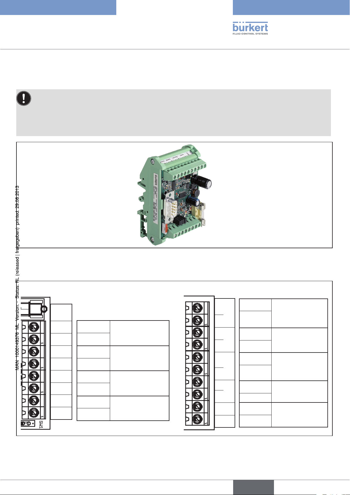
New electronic gas recovery with ident. no. 208373Figure 1 :
Pin assignment of the new electronic control, ident. no. 208373
Inputs
Impuls 1
GND
Diesel 1
GND
Impuls 2
GND
Diesel 2
GND
Configuration
+ Input
GND
+ Input
GND
+ Input
GND
+ Input
GND
Frequency input
Gasoline pulse
Side 1
Diesel identifier
Side 1
Frequency input
Gasoline pulse
Side 2
Diesel identifier
Side 2
Outputs
+ – + – + – + –
GND
+ 24V
Configuration
GND
+ Output
GND
+ Output
GND
+ Output
GND
+ Output
Ventil 1 Schütz 1 Ventil 2 Schütz 2
GND
+ Output
Motor contactor
control
Side 2
Valve control
Side 2
Motor contactor
control
Side 1
Valve control
Side 1
24 V supply
Pin assignment; new electronic gas recovery with ident. no. 208373Figure 2 :
The differences between the pin assignment for the electronic controls with old identification number are described below.
© 2010 Bürkert Werke GmbH Supplement 1012/00_EU-ML_00809478 / Original: DE
english
1
Page 2
2
Information on the replacement
of the electronic control
english
Type 1094
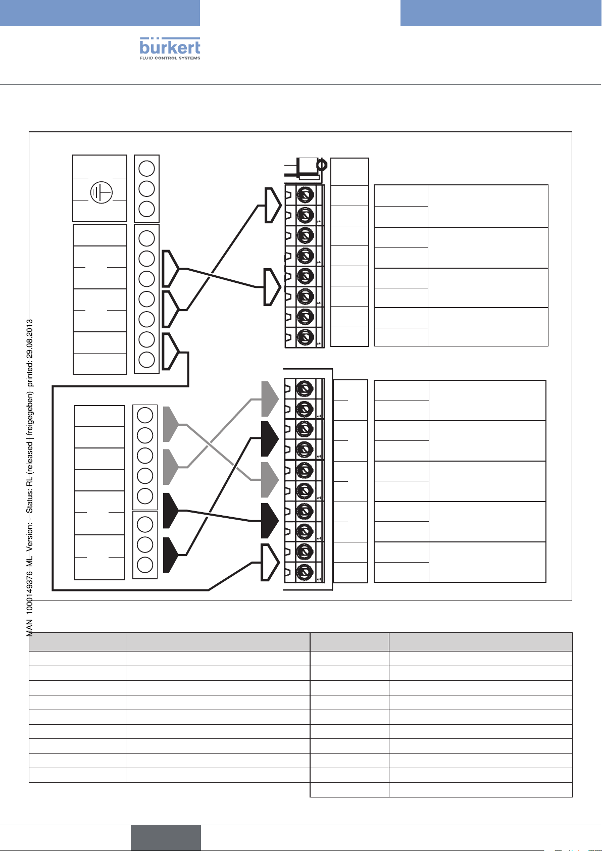
Pin assignment for replacement of the ident. no. 191675
Old ident. no. 191675
15 V
0 V
24 V
Pumpe 1 out
24 V
Pumpe 2 out
24 V
out
Eingang 2
Input 2
+ – + –
Eingang 1
Input 1
in
in
out
out
– + – +
Ventil 1
Valve 1
Ventil 2
Valve 2
Protective conductor
is replaced by ident. no. 208373
Assignment of inputs
Impuls 1
GND
Diesel 1
GND
Impuls 2
GND
Diesel 2
GND
+ Input
GND
+ Input
GND
+ Input
GND
+ Input
GND
Assignment of outputs
GND
+ Output
GND
+ Output
GND
+ Output
GND
+ – + – + – + –
GND
+ 24V
+ Output
Ventil 1 Schütz 1 Ventil 2 Schütz 2
GND
+ Output
Frequency input
Gasoline pulse
Side 1
Diesel identifier
Side 1
Frequency input
Gasoline pulse
Side 2
Diesel identifier
Side 2
Motor contactor control
Side 2
Valve control
Side 2
Motor contactor control
Side 1
Valve control
Side 1
24 V supply
Overview of assignment: Old → New
Labeling Pin assignment (old) Labeling Pin assignment (new)
Protective conductor
15 V out
Input 2 Input 2 and GND
Input 1 Input 1 and GND
0 V / 24 V in Supply GND / 24 V DC
Pumpe 1 / 24 V out Control of pump 1
Pumpe 2 / 24 V out Control of pump 2
Valve 1 Valve 1 (+ and –)
Valve 2 Valve 2 (+ and –)
→
→
→
Impuls 2 / GND Frequency input of gasoline pulse, side 2
→
Impuls 1 / GND Frequency input of gasoline pulse, side 1
→
GND / + 24 V 24 V supply
→
Schütz 1 Control of motor contactor, side 1
→
Schütz 2 Control of motor contactor, side 2
→
Ventil 1 Control of valve, side 1
→
Ventil 2 Control of valve, side 2
No longer available/required
No longer available
also Diesel 1 / 2 Diesel identifier sides 1 and 2
Page 3
3
Information on the replacement
of the electronic control
english
Type 1094
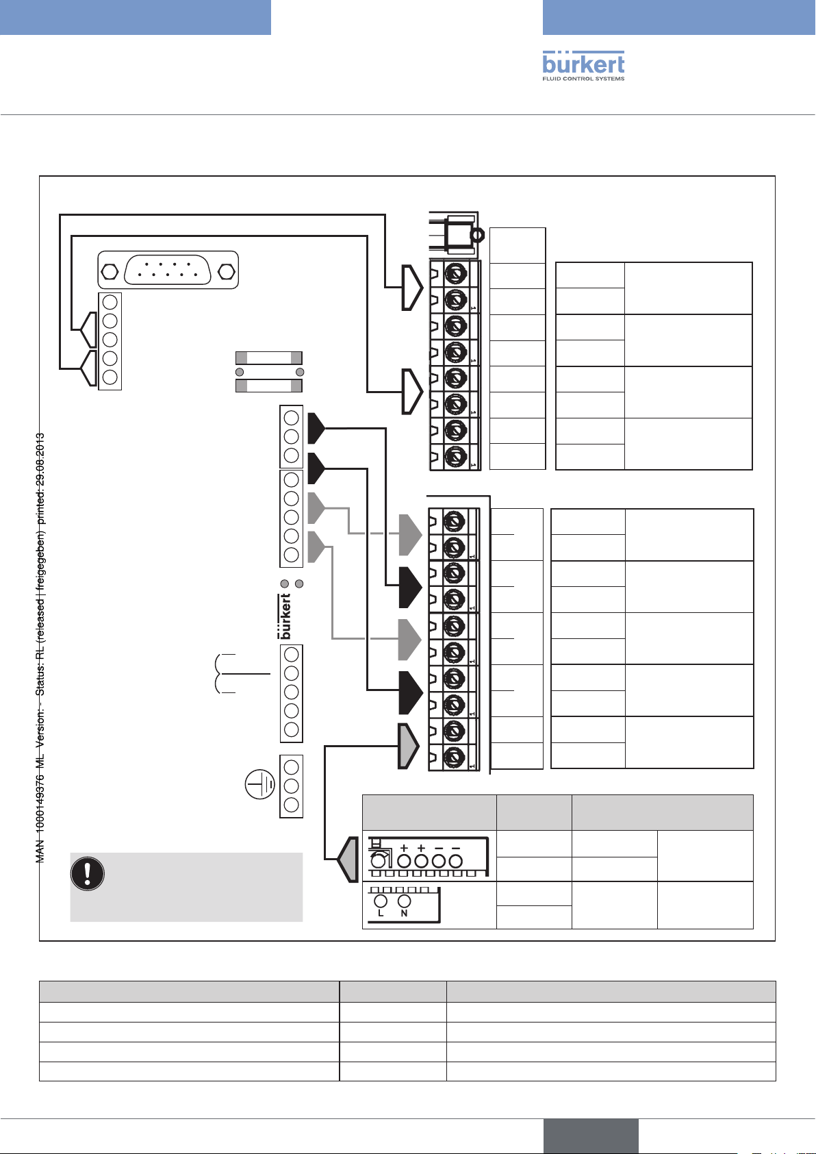
Pin assignment for replacement of the ident. no. 130561
Old ident. no. 130561
+ 15 V
Input B (+)
Input B (–)
Input A (+)
Input A (–)
Operating voltage
Selection 230 V / 115 V
Connection
Power supply unit
Valve B (+)
Valve B (–)
Valve A (+)
Valve A (–)
Pump B (+)
Pump B (–)
Pump A (+)
Pump A (–)
LEDs
230 V
115 V
N
L1
LEDs
is replaced by ident. no. 208373 and
ident. no. 770156 (power supply unit)
Assignment of gas recovery
Inputs
Impuls 1
GND
Diesel 1
GND
Impuls 2
GND
Diesel 2
GND
+ – + – + – + –
GND
+ 24V
Outputs
GND
+ Output
GND
+ Output
GND
+ Output
GND
+ Output
Ventil 1 Schütz 1 Ventil 2 Schütz 2
GND
+ Output
+ Input
GND
+ Input
GND
+ Input
GND
+ Input
GND
Frequency input
Gasoline pulse
Side 1
Diesel identifier
Side 1
Frequency input
Gasoline pulse
Side 2
Diesel identifier
Side 2
Motor contactor
control
Side 2
Valve control
Side 2
Motor contactor
control
Side 1
Valve control
Side 1
24 V supply
Power supply unit
ident. no. 770156
Protective conductor
Important!
Connect the power supply unit,
as illustrated on the right, to the
24 V supply.
Ident
ification
+
–
L
N
Overview of assignment: Old → New
Pin assignment (old) Labeling Pin assignment (new)
+ 15 V
Input B (+ and –)
Input A (+ and –)
Valve B (+ and –)
→
→
Impuls 2 / GND Frequency input of gasoline pulse, side 2
→
Impuls 1 / GND Frequency input of gasoline pulse, side 1
→
Ventil 2 Control of valve, side 2
No longer available
Pin assignment
24 V
GND
100 V AC to
240 V AC
Output voltage
Operating
voltage
Page 4
Type 1094
Information on the replacement
of the electronic control
Pin assignment (old) Labeling Pin assignment (new)
Valve A (+ and –)
Control of pump B (+ and –)
Control of pump A (+ and –)
Operating voltage (230 V or 115 V)
→
Ventil 1 Control of valve, side 1
→
Schütz 2 Control of motor contactor, side 2
→
Schütz 1 Control of motor contactor, side 1
→
- No longer required. Power supply unit operates at
voltages from 100 V AC to 240 V AC
Also: Diesel 1 / 2 Diesel identifier side 1 and side 2
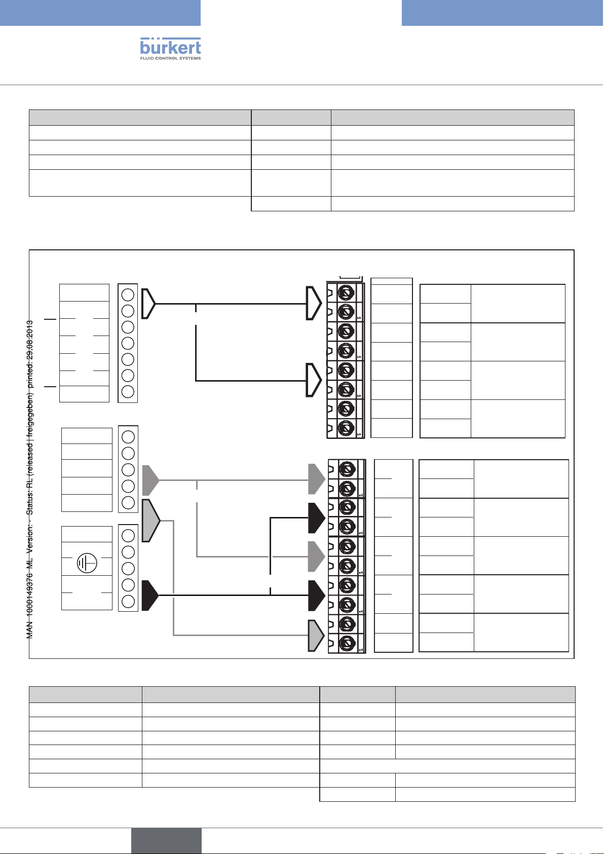
Pin assignment for replacement of the ident. no. 60651
Old ident. no. 60651
Inputs
0 V
1 2 3 4 5
Eingang / Input
not used
12 V out
Outputs
12 V in
not
Alarm out
used
Pumpe out
24 V out
24 V –
0 V
+ –
Ventil
Valve
or *
* leave other side
open
or *
or *
is replaced by ident. no. 208373
Inputs
Impuls 1
GND
Diesel 1
GND
Impuls 2
GND
Diesel 2
GND
+ – + – + – + –
GND
+ 24V
+ Input
GND
+ Input
GND
+ Input
GND
+ Input
GND
Outputs
GND
+ Output
GND
+ Output
GND
+ Output
GND
+ Output
Ventil 1 Schütz 1 Ventil 2 Schütz 2
GND
+ Output
Frequency input
Gasoline pulse
Side 1
Diesel identifier
Side 1
Frequency input
Gasoline pulse
Side 2
Diesel identifier
Side 2
Motor contactor
control
Side 2
Valve control
Side 2
Motor contactor
control
Side 1
Valve control
Side 1
24 V supply
Overview of assignment: Old → New
Labeling Pin assignment (old) Labeling Pin assignment (new)
Input 0 V / 1 Input GND and 1
→
Impuls1 / 2 Frequency input side 1 or 2
12 V out / 12 V in - No longer available
Pumpe out / 24 V out Control of pump
Output 24 V – / 0 V Operating voltage GND / + 24 V
Symb. for prot. conductor Protective conductor
Ventil / Valve + /– Valve (+ and –)
→
Schütz 1 / 2 Control of motor contactor side 1 or 2
→
GND / + 24 V 24 V supply
→
No longer available/required
→
Ventil 1 / 2 Control of valve side 1 or 2
also Diesel 1 / 2 Diesel identifier sides 1 and 2
4
english
Page 5

Typ 1094
Information zum Ersatz der
elektronischen Steuerung
Beschreibung für den Ersatz elektronischer Steuerungen zur
Gasrückführung
Wichtige Information!
Die neue elektronische Steuerung für die Gasrückführung mit der Ident-Nr. 208373 ersetzt die bisherige elektronischen Steuerungen mit der Ident-Nr. 191675 und 60651.
Die bisherige Steuerung mit der Ident-Nr. 130561 wird ebenfalls durch die neue elektronische Steuerung ersetzt,
jedoch in Verbindung mit dem Netzteil (Ident-Nr. 770156).
Neue elektronische Gasrückführung mit der Ident-Nr. 208373Bild 1:
Anschlussbelegung der neuen elektronischen Steuerung, Identnr. 208373
Eingänge
Impuls 1
GND
Diesel 1
GND
Impuls 2
GND
Diesel 2
GND
Belegung
+ Eingang
GND
+ Eingang
GND
+ Eingang
GND
+ Eingang
GND
Frequenzeingang
Benzinimpuls
Seite 1
Dieselkennung
Seite 1
Frequenzeingang
Benzinimpuls
Seite 2
Dieselkennung
Seite 2
Ausgänge
2
Ventil 2 Schütz
1
+ – + – + – + –
Ventil 1 Schütz
GND
+ 24V
Belegung
GND
+ Ausgang
GND
+ Ausgang
GND
+ Ausgang
GND
+ Ausgang
GND
+ Ausgang
Ansteuerung
Motorschütz
Seite 2
Ansteuerung Ventil
Seite 2
Ansteuerung
Motorschütz
Seite 1
Ansteuerung Ventil
Seite 1
Versorgung 24 V
Anschlussbelegung; neue elektronische Gasrückführung mit der Ident-Nr. 208373Bild 2:
Die Unterschiede der Anschlussbelegung zu den elektronischen Regelungen mit alter Identnummer sind nachfolgend beschrieben.
deutsch
5
Page 6

6
Information zum Ersatz der
elektronischen Steuerung
Typ 1094
deutsch
Anschlussbelegung bei Ersatz der Identnummer 191675
Alte Ident-Nr. 191675
15 V
0 V
24 V
Pumpe 1 out
24 V
Pumpe 2 out
24 V
out
Eingang 2
input 2
+ – + –
Eingang 1
Input 1
in
in
out
out
– + – +
Ventil 1
Valve 1
Ventil 2
Valve 2
Schutzleiter
wird ersetzt durch Ident-Nr. 208373
Belegung Eingänge
Impuls 1
GND
Diesel 1
GND
Impuls 2
GND
Diesel 2
GND
+ Eingang
GND
+ Eingang
GND
+ Eingang
GND
+ Eingang
GND
Belegung Ausgänge
GND
+ Ausgang
GND
+ Ausgang
GND
+ Ausgang
GND
+ – + – + – + –
GND
+ 24V
+ Ausgang
Ventil 1 Schütz 1 Ventil 2 Schütz 2
GND
+ Ausgang
Frequenzeingang
Benzinimpuls
Seite 1
Dieselkennung
Seite 1
Frequenzeingang
Benzinimpuls
Seite 2
Dieselkennung
Seite 2
Ansteuerung Motorschütz
Seite 2
Ansteuerung Ventil
Seite 2
Ansteuerung Motorschütz
Seite 1
Ansteuerung Ventil
Seite 1
Versorgung 24 V
Übersicht Zuordnung: Alt → Neu
Beschriftung Anschlussbelegung (alt) Beschriftung Anschlussbelegung (neu)
Schutzleiter
15 V out
Eingang 2 Eingang 2 und GND
Eingang 1 Eingang 1 und GND
0 V / 24 V in Versorgung GND / 24 V DC
Pumpe 1 / 24 V out Ansteuerung Pumpe 1
Pumpe 2 / 24 V out Ansteuerung Pumpe 2
Ventil 1 Ventil 1 (+ und –)
Ventil 2 Ventil 2 (+ und –)
→
→
→
Impuls 2 / GND Frequenzeingang Benzinimpuls, Seite 2
→
Impuls 1 / GND Frequenzeingang Benzinimpuls, Seite 1
→
GND / + 24 V Versorgung 24 V
→
Schütz 1 Ansteuerung Motorschütz, Seite 1
→
Schütz 2 Ansteuerung Motorschütz, Seite 2
→
Ventil 1 Ansteuerung Ventil, Seite 1
→
Ventil 2 Ansteuerung Ventil, Seite 2
nicht mehr vorhanden/nötig
nicht mehr vorhanden
zusätzlich Diesel 1 / 2 Dieselkennung Seiten 1 und 2
Page 7

7
Information zum Ersatz der
elektronischen Steuerung
Typ 1094
deutsch
Anschlussbelegung bei Ersatz der Identnummer 130561
Alte Ident-Nr. 130561
+ 15 V
Eingang B (+)
Eingang B (–)
Eingang A (+)
Eingang A (–)
Betriebsspannung
Auswahl 230 V / 115 V
Ventil B (+)
Ventil A (+)
Pumpe B (+)
Pumpe B (–)
Pumpe A (+)
Pumpe A (–)
Anschluss
Netzteil
Ventil B (–)
Ventil A (–)
LEDs
230 V
115 V
N
L1
LEDs
wird ersetzt durch Ident-Nr. 208373 und
Ident-Nr. 770156 (Netzteil)
Belegung Gasrückführung
Eingänge
Impuls 1
GND
Diesel 1
GND
Impuls 2
GND
Diesel 2
GND
+ – + – + – + –
GND
+ 24V
Ausgänge
GND
+ Ausgang
GND
+ Ausgang
GND
+ Ausgang
GND
+ Ausgang
Ventil 1 Schütz 1 Ventil 2 Schütz 2
GND
+ Ausgang
+ Eingang
GND
+ Eingang
GND
+ Eingang
GND
+ Eingang
GND
Frequenzeingang
Benzinimpuls
Seite 1
Dieselkennung
Seite 1
Frequenzeingang
Benzinimpuls
Seite 2
Dieselkennung
Seite 2
Ansteuerung
Motorschütz
Seite 2
Ansteuerung Ventil
Seite 2
Ansteuerung
Motorschütz
Seite 1
Ansteuerung Ventil
Seite 1
Versorgung 24 V
Schutzleiter
Wichtig!
Das Netzteil, wie rechts dargestellt, an die Versorgung 24 V
anschließen.
Netzteil
Ident-Nr. 770156
Kennzeichnung
+
–
L
N
Anschlussbelegung
24 V
GND
100 V AC bis
240 V AC
Übersicht Zuordnung: Alt → Neu
Anschlussbelegung (alt) Beschriftung Anschlussbelegung (neu)
+ 15 V
Eingang B (+ und –)
Eingang A (+ und –)
Ventil B (+ und –)
Ventil A (+ und –)
→
→
Impuls 2 / GND Frequenzeingang Benzinimpuls, Seite 2
→
Impuls 1 / GND Frequenzeingang Benzinimpuls, Seite 1
→
Ventil 2 Ansteuerung Ventil, Seite 2
→
Ventil 1 Ansteuerung Ventil, Seite 1
nicht mehr vorhanden
Ausgangsspannung
Betriebsspannung
Page 8

Typ 1094
Information zum Ersatz der
elektronischen Steuerung
Anschlussbelegung (alt) Beschriftung Anschlussbelegung (neu)
Ansteuerung Pumpe B (+ und –)
Ansteuerung Pumpe A (+ und –)
Betriebsspannung (230 V oder 115 V)
→
Schütz 2 Ansteuerung Motorschütz, Seite 2
→
Schütz 1 Ansteuerung Motorschütz, Seite 1
→
- Nicht mehr nötig. Netzteil arbeitet mit Spannungen von
100 V AC bis 240 V AC
Zusätzlich: Diesel 1 / 2 Dieselkennung Seite 1 und Seite 2
Anschlussbelegung bei Ersatz der Identnummer 60651
Alte Ident-Nr. 60651
Eingänge
0 V
Eingang / Input
nicht belegt
12 V out
Ausgänge
12 V in
nicht
Alarm out
belegt
Pumpe out
24 V out
24 V –
0 V
Ventil
Valve
wird ersetzt durch Ident-Nr. 208373
Eingänge
1 2 3 4 5
oder *
* jeweils andere
Impuls 1
GND
Diesel 1
GND
Impuls 2
GND
Diesel 2
GND
+ Eingang
GND
+ Eingang
GND
+ Eingang
GND
+ Eingang
GND
Frequenzeingang
Benzinimpuls
Seite 1
Dieselkennung
Seite 1
Frequenzeingang
Benzinimpuls
Seite 2
Dieselkennung
Seite 2
Seite offen lassen
Ausgänge
GND
oder *
+ –
oder *
+ – + – + – + –
GND
+ 24V
+ Ausgang
GND
+ Ausgang
GND
+ Ausgang
GND
+ Ausgang
Ventil 1 Schütz 1 Ventil 2 Schütz 2
GND
+ Ausgang
Ansteuerung
Motorschütz
Seite 2
Ansteuerung Ventil
Seite 2
Ansteuerung
Motorschütz
Seite 1
Ansteuerung Ventil
Seite 1
Versorgung 24 V
Übersicht Zuordnung: Alt → Neu
Beschriftung Anschlussbelegung (alt) Beschriftung Anschlussbelegung (neu)
Eingang 0 V / 1 Eingang GND und 1
→
Impuls1 / 2 Frequenzeingang Seite 1 oder 2
12 V out / 12 V in - nicht mehr vorhanden
Pumpe out / 24 V out Ansteuerung Pumpe
Ausgang 24 V – / 0 V Betriebsspannung GND / + 24 V
Symbol Schutzleiter Schutzleiter
Ventil / Valve + /– Ventil (+ und –)
→
Schütz 1 / 2 Ansteuerung Motorschütz Seite 1 od. 2
→
GND / + 24 V Versorgung 24 V
→
nicht mehr vorhanden/notwendig
→
Ventil 1 / 2 Ansteuerung Ventil Seite 1 oder 2
zusätzlich Diesel 1 / 2 Dieselkennung Seiten 1 und 2
8
deutsch
Page 9

Type 1094
Information concernant le
remplacement de la commande
électronique
Description du remplacement des commandes électroniques
pour la recirculation des gaz
Information importante !
La nouvelle commande électronique pour la recirculation des gaz avec le n° ID 208373 remplace les commandes
électroniques actuelles avec les n° ID 191675 et 60651.
La commande actuelle avec le n° ID 130561 est également remplacée par la nouvelle commande électronique,
toutefois avec le bloc d'alimentation (n° ID 770156).
Nouvelle recirculation électronique des gaz avec le n° ID 208373Fig. 1:
Affectation du raccordement de la nouvelle commande électronique, n° ID 208373
Entrées
Impuls 1
GND
Diesel 1
GND
Impuls 2
GND
Diesel 2
GND
Affectation
+ entrée
GND
+ entrée
GND
+ entrée
GND
+ entrée
GND
Entrée de fréquence
Impulsion d'essence
Côté 1
Code diesel
Côté 1
Entrée de fréquence
Impulsion d'essence
Côté 2
Code diesel
Côté 2
Sorties
+ – + – + – + –
GND
+ 24 V
Affectation
GND
+ sortie
GND
+ sortie
GND
+ sortie
GND
+ sortie
Ventil 1 Schütz 1 Ventil 2 Schütz 2
GND
+ sortie
Commande contacteur du moteur
Côté 2
Commande vanne
Côté 2
Commande contacteur du moteur
Côté 1
Commande vanne
Côté 1
Alimentation 24 V
Affectation du raccordement ; nouvelle recirculation électronique des gaz avec le n° ID 208373Fig. 2:
Les différences au niveau de l'affectation du raccordement par rapport aux régulations électroniques avec l'ancien
numéro d'identification sont décrites ci-après.
français
9
Page 10

10
Information concernant le
remplacement de la commande
électronique
Type 1094
français
Affectation du raccordement avec remplacement du n° ID 191675
Ancien n° ID 191675
15 V
0 V
24 V
Pumpe 1 out
24 V
Pumpe 2 out
24 V
out
Eingang 2
Input 2
+ – + –
Eingang 1
Input 1
in
in
out
out
– + – +
Ventil 1
Valve 1
Ventil 2
Valve 2
Conducteur de
protection
remplacé par le n° ID 208373
Affectation des entrées
Impuls 1
GND
Diesel 1
GND
Impuls 2
GND
Diesel 2
GND
+ entrée
GND
+ entrée
GND
+ entrée
GND
+ entrée
GND
Affectation des sorties
GND
+ sortie
GND
+ sortie
GND
+ sortie
GND
+ – + – + – + –
GND
+ 24V
+ sortie
Ventil 1 Schütz 1 Ventil 2 Schütz 2
GND
+ sortie
Entrée de fréquence
Impulsion d'essence
Côté 1
Code diesel
Côté 1
Entrée de fréquence
Impulsion d'essence
Côté 2
Code diesel
Côté 2
Commande contacteur du
moteur
Côté 2
Commande vanne
Côté 2
Commande contacteur du
moteur
Côté 1
Commande vanne
Côté 1
Alimentation 24 V
Vue d'ensemble des affectations : Ancienne → Nouvelle
Informations Affectation du raccordement (ancienne) Informations Affectation du raccordement (nouvelle)
Conducteur de protection
15 V out
Eingang / Input 2 Entrée 2 et GND
→
→
→
Impuls 2 / GND Entrée de fréquence impulsion
n'existe plus/n'est plus nécessaire
n'existe plus
d'essence, côté 2
Eingang / Input 1 Entrée 1 et GND
→
Impuls 1 / GND Entrée de fréquence impulsion
d'essence, côté 1
0 V / 24 V in Alimentation GND / 24 V DC
Pumpe 1 / 24 V out Commande pompe 1
Pumpe 2 / 24 V out Commande pompe 2
Ventil / Vanne 1 Vanne 1 (+ et –)
Ventil / Vanne 2 Vanne 2 (+ et –)
→
GND / + 24 V Alimentation 24 V
→
Schütz 1 Commande contacteur du moteur, coté 1
→
Schütz 2 Commande contacteur du moteur, coté 2
→
Ventil 1 Commande vanne, coté 1
→
Ventil 2 Commande vanne, coté 2
en plus Diesel 1 / 2 Code diesel, côtés 1 et 2
Page 11

11
Information concernant le
remplacement de la commande
électronique
Type 1094
français
Affectation du raccordement avec remplacement du n° ID 130561
Ancien n° ID 130561
+ 15 V
Entrée B (+)
Entrée B (–)
Entrée A (+)
Entrée A (–)
Tension de service
Sélection 230 V / 115 V
Raccordement
Bloc d'alimentation
Vanne B (+)
Vanne B (–)
Vanne A (+)
Vanne A (–)
Pompe B (+)
Pompe B (–)
Pompe A (+)
Pompe A (–)
DEL
230 V
115 V
N
L1
DEL
remplacé par n° ID 208373 et
n° ID 770156 (bloc d'alimentation)
Affectation recirculation des gaz
Entrées
Sorties
GND
+ sortie
GND
+ sortie
GND
+ sortie
GND
+ sortie
Ventil 1 Schütz 1 Ventil 2 Schütz 2
GND
+ sortie
+ entrée
GND
+ entrée
GND
+ entrée
GND
+ entrée
GND
Impuls 1
GND
Diesel 1
GND
Impuls 2
GND
Diesel 2
GND
+ – + – + – + –
GND
+ 24V
Entrée de fréquence
Impulsion d'essence
Côté 1
Code diesel
Côté 1
Entrée de fréquence
Impulsion d'essence
Côté 2
Code diesel
Côté 2
Commande contacteur
du moteur
Côté 2
Commande vanne
Côté 2
Commande contacteur
du moteur
Côté 1
Commande vanne
Côté 1
Alimentation 24 V
Conducteur
de protection
Important !
Raccorder le bloc d'alimentation
à l'alimentation 24 V comme
cela est représenté à droite.
Bloc d'alimentation
n° ID 770156
Identification
+
–
L
N
Affectation du raccordement
24 V
GND
100 V AC à
240 V AC
Vue d'ensemble des affectations : Ancienne → Nouvelle
Affectation du raccordement (ancienne) Informations Affectation du raccordement (nouvelle)
+ 15 V
Entrée B (+ et –)
Entrée A (+ et –)
Vanne B (+ et –)
Vanne A (+ et –)
→
→
Schütz 2 / GND Entrée de fréquence impulsion d'essence, côté 2
→
Schütz 1 / GND Entrée de fréquence impulsion d'essence, côté 1
→
Ventil 2 Commande vanne, coté 2
→
Ventil 1 Commande vanne, coté 1
n'existe plus
Tension de
sortie
Tension de
service
Page 12

Type 1094
Information concernant le
remplacement de la commande
électronique
Affectation du raccordement (ancienne) Informations Affectation du raccordement (nouvelle)
Commande pompe B (+ et –)
Commande pompe A (+ et –)
Tension de service (230 V ou 115 V)
→
Schütz 2 Commande contacteur du moteur, coté 2
→
Schütz 1 Commande contacteur du moteur, coté 1
→
- N'est plus nécessaire. Le bloc d'alimentation fonctionne avec
des tensions allant de 100 V AC à 240 V AC
En plus : Diesel 1 / 2 Code diesel, côtés 1 et 2
Affectation du raccordement avec remplacement du n° ID 60651
Ancien n° ID 60651
Entrées
0 V
Eingang / Input
non affecté
12 V out
Sorties
12 V in
non
Alarm out
affecté
Pumpe out
24 V out
24 V –
0 V
Ventil
Valve
remplacé par le n° ID 208373
Entrées
1 2 3 4 5
ou *
* laisser l'autre côté
Impuls 1
GND
Diesel 1
GND
Impuls 2
GND
Diesel 2
GND
+ entrée
GND
+ entrée
GND
+ entrée
GND
+ entrée
GND
Entrée de fréquence
Impulsion d'essence
Côté 1
Code diesel
Côté 1
Entrée de fréquence
Impulsion d'essence
Côté 2
Code diesel
Côté 2
ouvert
Sorties
GND
ou *
+ –
ou *
+ – + – + – + –
GND
+ 24V
+ sortie
GND
+ sortie
GND
+ sortie
GND
+ sortie
Ventil 1 Schütz 1 Ventil 2 Schütz 2
GND
+ sortie
Commande contacteur
du moteur
Côté 2
Commande vanne
Côté 2
Commande contacteur
du moteur
Côté 1
Commande vanne
Côté 1
Alimentation 24 V
Vue d'ensemble des affectations : Ancienne → Nouvelle
Informations Affectation du raccordement (ancienne) Informations Affectation du raccordement (nouvelle)
Entrée 0 V / 1 Entrée GND et 1
→
Impuls 1 / 2 Entrée de fréquence, côté 1 ou 2
12 V out / 12 V in - n'existe plus
Pumpe out /
Commande pompe
24 V out
Sortie 24 V – / 0 V Tension de service GND / + 24 V
Symbole conducteur
Conducteur de protection
→
Schütz 1 / 2 Commande contacteur du moteur,
côté 1 ou 2
→
GND / + 24 V Alimentation 24 V
→
n'existe plus/n'est plus nécessaire
de protection
Ventil / Valve + /– Vanne (+ et –)
→
Ventil 1 / 2 Commande vanne, côté 1 ou 2
en plus Diesel 1 / 2 Code diesel, côtés 1 et 2
12
français
 Loading...