

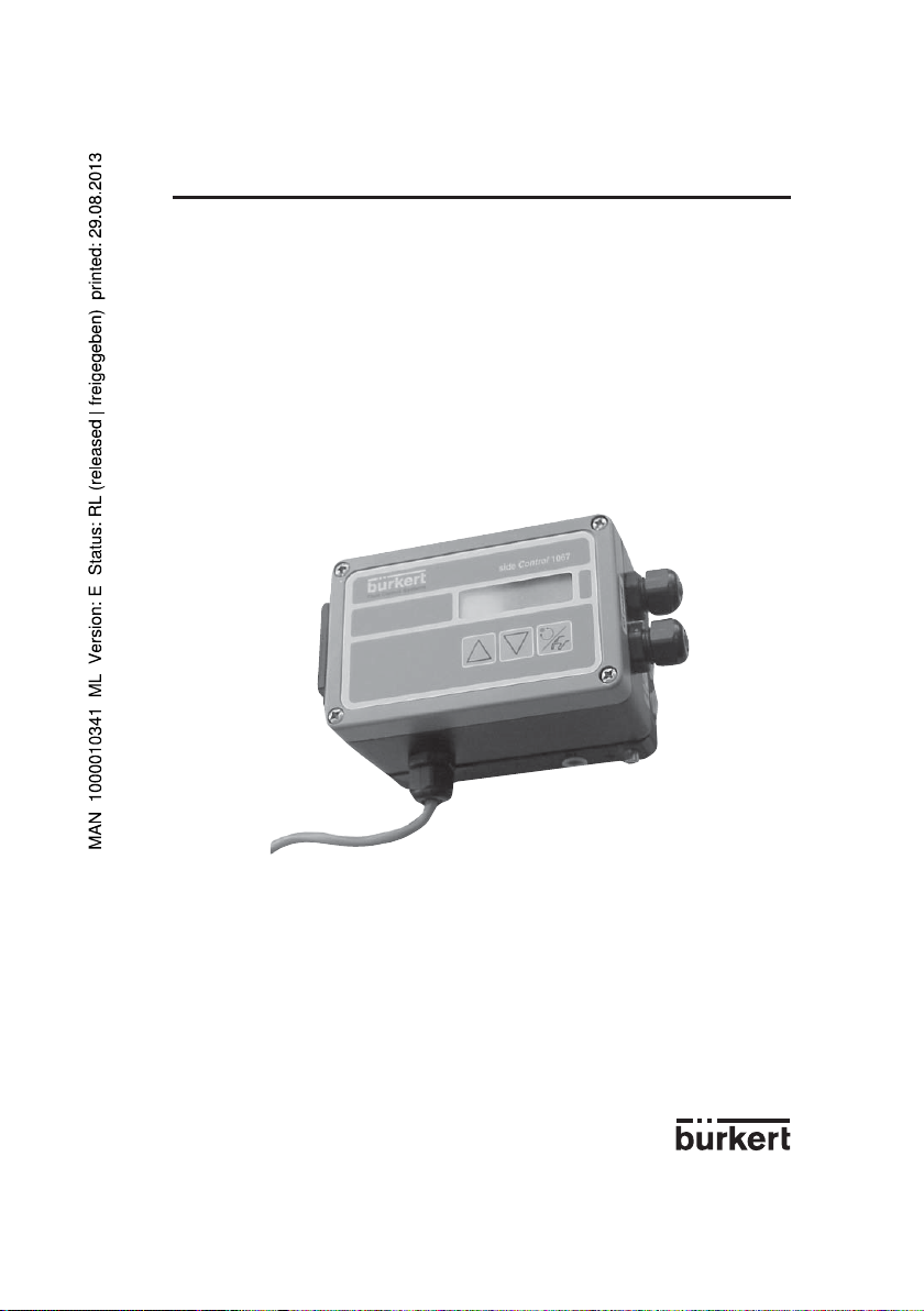
Page 1
POSITIONER 1067
BEDIENUNGSANLEITUNG .........................................................................................D-1
INSTRUCTION MANUAL .............................................................................................E-1
MANUEL UTILISATEUR ..............................................................................................F-1
*****
©BÜRKERT 1996 00420832_Sep05-Ind_D
Technische Änderungen vorbehalten
We reserve the right to make technical changes without notice
Sous réserve de modifications techniques
D-1-
Page 2

POSITIONER 1067INHALTSVERZEICHNIS
1 EINFÜHRUNG .................................................................................................................... D-3
1.1 Auspacken und Kontrolle ............................................................................................................................ D-3
1.2 Allgemeine Hinweise zum Gebrauch und zur Sicherheit .................................................................... D-3
1.3 Elektromagnetische Verträglichkeit .......................................................................................................... D-3
2 BESCHREIBUNG ...............................................................................................................D-4
2.1 Merkmale und Anwendungsmöglichkeiten .............................................................................................D-4
2.2 Aufbau ............................................................................................................................................................. D-6
2.3 Funktionsprinzip ............................................................................................................................................ D-7
2.4 Sicherheitsstellung .......................................................................................................................................D-8
2.5 Technische Daten ......................................................................................................................................... D-9
3 INSTALLATION ................................................................................................................. D-10
3.1 Anbau und Montage ..................................................................................................................................D-10
3.1.1 Anbau des Positioners an ein Stetigventil mit Membranantrieb (nach NAMUR) ............D-10
3.1.2 Anbau des Positioners an ein Stetigventil mit Kolbenantrieb .............................................D-12
3.1.3 Aufbau des Positioners in getrennter Ausführung ..................................................................D-14
3.1.4 Anbau des Positioners an ein Stetigventil mit Drehantrieb ..................................................D-16
3.2 Fluidische Anschlüsse ...............................................................................................................................D-17
3.3 Elektrische Anschlüsse .............................................................................................................................D-18
4 BEDIENUNG ..................................................................................................................... D-19
4.1 Bedien- und Anzeigeelemente ................................................................................................................D-19
4.2 Bedienebenen .............................................................................................................................................D-19
4.3 Inbetriebnahme............................................................................................................................................D-20
4.4 Prozessbedienen ........................................................................................................................................D-22
4.4.1 Bedeutung der LED und der Tasten in der Ebene Prozessbedienen ................................D-22
4.4.2 Anzeigemöglichkeiten ...................................................................................................................D-22
4.5 Konfigurieren ................................................................................................................................................D-24
4.5.1 Zusatzfunktionen ............................................................................................................................D-24
4.5.2 Konfiguriermenü ..............................................................................................................................D-26
4.5.3 Bedeutung der Tasten in der Konfigurierebene ......................................................................D-28
4.5.4 Erläuterungen zu den Grund- und Zusatzfunktionen .............................................................D-28
4.6 Handbetätigung ..........................................................................................................................................D-37
4.7 Struktur des Positioners ............................................................................................................................D-38
5 WARTUNG ........................................................................................................................ D-39
5.1 Fehlermeldungen ........................................................................................................................................D-39
5.2 Ersatzteile - Bestellnummern ...................................................................................................................D-39
ANHANG ........................................................................................................................... D-40
A1: Eigenschaften von PID Reglern .......................................................................................................D-40
A2: Einstellregeln für PID Regler ............................................................................................................D-44
A3: Optionsplatine für 4-20 mA analoge Stellungsrückmeldung ...................................................D-47
A4: Optionsplatine für binäre Stellungsrückmeldung/Booster ........................................................D-48
A5: Anschluss-Beispiele mit dem Positioner 1067 ............................................................................D-50
D-2-
Page 3

POSITIONER 10671 EINFÜHRUNG
!
Sehr geehrter Kunde,
Um die vielfältigen Vorteile, die Ihnen das Produkt
bietet, voll nutzen zu können, befolgen Sie bitte
unbedingt unseren Rat und
LESEN SIE DIESE BEDIENUNGS ANLEITUNG GRÜNDLICH, BEVOR SIE
DAS GERÄT MONTIEREN UND IN BETRIEB NEHMEN.
1.1 Auspacken und Kontrolle
Bitte überprüfen Sie die Lieferung auf Vollständigkeit und Transportschäden. Zur Standardlieferung gehören:
-1Stück 1067
-1 Bedienungsanleitung
Bei Verlust oder Schäden wenden Sie sich an
Ihre Bürkert Niederlassung.
1.2 Allgemeine Hinweise zum
Gebrauch und zur Sicherheit
Diese Druckschrift enthält keine Garantiezusagen. Wir verweisen hierzu auf unsere allgemeinen
Verkaufs- und Liefer bedingungen.
Der Anwender muß zur Sicherung einer einwandfreien Funktion und langen Lebens-dauer des
Positioners diese Bedienungsanleitung beachten
sowie die Einsatzbedingungen und zulässigen
Daten gemäß Datenblatt einhalten. Das Inbetriebsetzungs- und Wartungspersonal muß eine
Ausbildung und Befähigung für diese Tätigkeit
besitzen.
Durch entsprechende Maßnahmen sind unbeabsichtigte Betätigungen und daraus resultierende Beeinträchtigungen des Prozesses
auszuschließen. Für den Instandsetzungsfall sind
sichere elektrische Trenn- und medientechnische Absperrvorrichtungen vorzusehen. Ist der
Positioner Teil eines komplexen Automatisierungssystems, so ist nach einer Unterbrechung
ein definierter und kontrollierter Wiederanlauf des
Automa tisierungs systems gemäß Anleitung zu
gewährleisten.
Während des Betriebes, der Wartung und der
Reparatur des Positioners sind die geltenden
Unfallverhütungs- und Sicherheitsbestimmungen
für elektrische Geräte zu beachten.
Reparaturen dürfen nur durch autorisiertes Fachpersonal vorgenommen werden.
Dieses Symbol erscheint in der Bedienungsanleitung jedesmal wenn besondere Vorsicht geboten
ist, um eine einwandfreie Installation, Funktion und
Betriebssicherheit des Gerätes zu
gewährleisten.
1.3 Elektromagnetische
Verträglichkeit
Hiermit wird bestätigt, dass dieses Produkt den
wesentlichen Schutzanforderungen entspricht, die
in der Richtlinie des Rates zur Angleichung der
Rechtsvorschriften der Mitgliedstaaten über die
elektromagnetische Verträglichkeit
(89/336/EWG) festgelegt sind.
Dazu müssen die elektrischen Anschlussvorschriften befolgt werden.
Mastercode
In den verschiedenen Bedienebenen kann eine
unbefugte Bedienung durch einen frei wählbaren
Benutzercode ausgeschlossen werden. Unabhängig davon existiert ein fest einprogrammierter,
nicht veränderbarer Mastercode, mit dem man
alle Bedienhandlungen ausführen kann. Dieser
vierstellige Mastercode steht am unteren
Rand dieser Seite. Er kann ausgeschnitten und
getrennt von dieser Bedienungsanleitung aufbewahrt werden.
Master code:
6568
D-3-
Page 4

2 BESCHREIBUNG
POSITIONER 1067
2.1 Merkmale und Anwendungsmöglichkeiten (Überblick)
Der Positioner 1067 ist ein elektropneumatischer Stellungsregler für pneumatisch betätigte Stetigventile. Das Gerät umfaßt die Hauptfunktionsgruppen Wegmeßsystem, elektropneumatisches Stellsystem
und Mikroprozessorelektronik. Das Wegmeßsystem mißt die aktuelle Position des Stetigventils. Die
Mikroprozessorelektronik vergleicht die aktuelle Position (Istwert) kontinuierlich mit einem über den
Einheitssignaleingang vorgegebenen Stellungssollwert und führt das Ergebnis dem Stellungsregler
zu. Liegt eine Regeldifferenz vor, wird durch das elektropneumatische Stellsystem eine entsprechende
Korrektur der Ist-Position herbeigeführt.
Der Positioner 1067 kann an unterschiedliche Stetigventile angebaut werden (z. B. an Ventile mit
Kolben-, Membran- oder Drehantrieb; einfach- oder doppeltwirkend). In diesem Zusammenhang
werden drei Basis-Gerätevarianten angeboten, die sich bezüglich der Befestigungsmöglichkeiten und
des Wegmeßsystems unterscheiden. Bei der Gerätevariante 1 wird ein gerätinternes Wegmeßsystem
verwendet, das als Drehpotentiometer ausgeführt ist.
Bei der Gerätevariante 2 dient ein externes Linearpotentiometer als Wegmeßsystem.
Bei der Gerätevariante 3 dient ein externes Linearpotentiometer als Wegmeßsystem und der getrennte
Positioner wird an eine DIN-Schiene angebaut.
Im Positioner ist zusätzlich ein PID-Regler implementiert, mit dem außer der eigentlichen Stellungsregelung auch eine Prozeßregelung (z. B. Niveau, Druck, Durchfluß, Temperatur) im Sinne einer Kaskadenregelung durchgeführt werden kann.
Zur Bedienung des Positioners ist ein LCD-Display und ein Tastenfeld mit drei Tasten vorhanden. Es
wurde ein niveaugestuftes Bedienkonzept mit folgenden Bedienebenen realisiert:
- Prozeßbedienen
In dieser Ebene kann zwischen Automatik- und Handbetrieb umgeschaltet und eine Handbetätigung
durchgeführt werden.
- Konfi gurieren
Die Konfigurierebene dient dazu, bei der Inbetriebnahme bestimmte Grundfunktionen zu spezifizieren
und bei Bedarf Zusatzfunktionen zu konfigurieren.
D-4-
Page 5

Abb. 1 Übersichtsschema des Positioners 1067
Stellungsregler mit Zusatz -funktionen,
z. B. :
- Dichtschließfunktion
- Hubbegrenzung
- Stellgeschwindigkeitsbegrenzung
- Signalbereichsaufteilung
- Korrekturkennlinien
- Unempfindlichkeitsbereich
- Sicherheitsposition
Zusätzlich integrierter Prozeßregler mit
folgenden Eigenschaften:
- Einstellbare Parameter
- Skalierbare Eingänge
- Sollwertvorgabe über
Einheitssignaleingang oder Tasten
Automatische Anpassung des
Stellungsreglers an das verwendete
Stellventil
Hirarchisches Bedienkonzept zur
einfachen niveaugestuften Bedienung
POSITIONER 10672 BESCHREIBUNG
Eingang für Stellungsoder Prozeßsollwert
0...10 V
0...20 mA
4...20 mA
Eingang für Prozeßistwert
4...20 mA
Binär-Eingang (Kontakt)
24 VDC
Merkmale, Funktionen
Positioner
Eingänge
1067
Versorg.
Bedienung
D-5-
Analog Ausgang (Option)
Ausgang
Page 6
POSITIONER 10672 BESCHREIBUNG
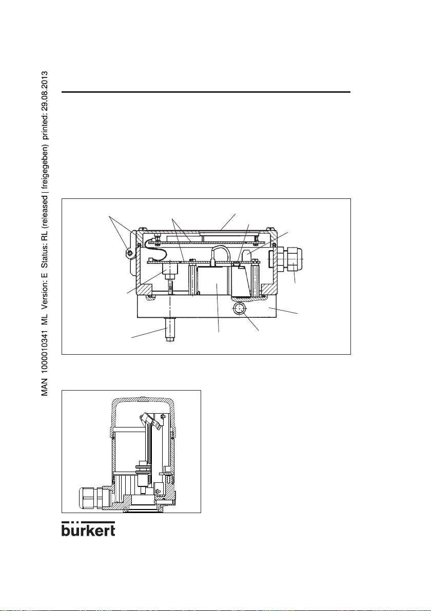
2.2 Aufbau
Der Positioner besteht aus folgenden Hauptbaugruppen:
- Gehäuse mit Deckel (Aluminium),
- Internes Wegmeßsystem (Drehpotentiometer) zur Messung der Ventilposition,
- Mikroprozessor / Elektronik zur Meßsignalverarbeitung und Regelung,
- Magnetventile zum Stellen eines Stetigventils,
- Fluidikplatte mit Fluidikanschlüssen,
- Anschlußklemmen und Kabelverschraubungen,
- Display und Tastenfeld.
Abb. 2 Schnittbild des Positioners mit geräteinternem Wegmeßsystem (Variante 1)
Aluminium Gehäuse mit
Deckel und Scharnier
Elektronik
Display und Tastenfeld
Handbetätigung
Anschlußklemme
Internes Wegmeß system zur Ankopplung
nach NAMUR
Wegsensor-Welle
Bei der Gerätevariante 2 des Positioners wird anstelle des internen Wegmeßsystems ein externes
Wegmeßsystem verwendet (Abb. 3), das als Linearpotentiometer ausgeführt ist.
Magnetventil
Fluidikanschluß
Kabelverschraubung
Fluidikplatte
Abb. 3 Ansicht des externen Wegmeßsystem (für Varianten 2 und 3)
D-6-
Page 7
2 BESCHREIBUNG
POSITIONER 1067
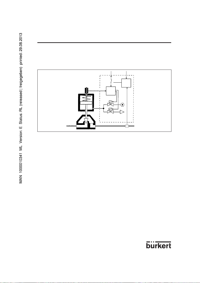
2.3 Funktionsprinzip
Abbildung 4 zeigt das Funktionsschema des Positioners im Zusammenspiel mit einem Kolbenstellventil.
Zur Messung der Ist-Position dient dabei ein externes Wegmeßsystem (bei Varianten 2 und 3).
Abb. 4 Funktionsschema
Wegmess-System
Stellventil
Über das Wegmeßsystem wird die Stellung (Ist-Position) des Ventilantriebs ermittelt. Im Positioner
wird das der Ist-Position entsprechende Signal kontinuierlich mit dem der Soll-Position zugeordneten
Signal verglichen und die Regeldifferenz (Regelabweichung) gebildet. Entsprechend der Regeldifferenz
werden Impulse unterschiedlicher Länge an die Magnetventile des elektropneumatischen Stellsystems
geleitet, über die die Zu- und Abluft zum Stellen des Stellantriebs eines Stetigventils gesteuert wird.
Die Soll-Position kann entweder über einen Einheitssignaleingang von außen (z. B. von Hand oder über
einen externen Regler) oder über den geräteinternen Prozeßregler vorgegeben werden. Im letzteren Fall
wird der Prozeßsollwert an den Einheitssignaleingang angelegt oder über die Tastatur vorgegeben und
ein Vergleich mit der zu regelnden Prozeßgröße (z. B. Durchfluß, Druck, Niveau, Temperatur) durchgeführt (Abb. 4).
Wird die Soll-Position von außen über den dafür vorgesehenen Einheitssignaleingang vorgegeben, der
interne Prozeßregler also nicht benutzt, dann arbeitet das Gerät nur als Stellungsregler (Abb. 5). Der
Stellungsregler ist im Mikroprozessor als PD-Regler implementiert. Dem Reglerausgang ist ein PWMGlied (Pulsweitenmodulation) nachgeschaltet, über dessen Ausgänge B1 und E1 die Magnetventile zum
Be- und Entlüften des Stellantriebs angesteuert werden. Bei positiver Regeldifferenz werden Impulse
(PWM-Signale) am Ausgang B1 zum Schalten der Zuluft und bei negativer Regeldifferenz Impulse am
Ausgang E1 zum Schalten der Abluft ausgegeben.
Der Positioner ist sowohl für einfachwirkende als auch für doppeltwirkende Stellantriebe lieferbar. Für
einen Einsatz bei doppeltwirkenden Stellantrieben besitzt das PWM-Glied zwei weitere Ausgänge B2
und E2, über die die beiden zusätzlich vorhandenen Magnetventile zur Be- bzw. Entlüftung angesteuert
werden.
Wird der geräteinterne Prozeßregler genutzt, dann ist er Bestandteil eines übergeordneten Regelkreises (Hauptregelkreis). Die zuvor erwähnte Stellungsregelung läuft jetzt in einem untergeordneten
Hilfsregelkreis ab. Insgesamt ergibt sich somit eine Kaskadenregelung (Abb. 6). Der geräteinterne
Prozeßregler (Hauptregler) ist als PID-Regler implementiert (Z1 und Z2 stellen Störgrößen dar).
Externer
Stellungssollwert
Ist-Position
SollPosition
Stellungsregler
Magnetventile
Prozeßsollwert
Prozeßregler
Zuluft
Abluft
Sensor
Prozeßwert (Druck, Durchfluß, Niveau...)
D-7-
Page 8

2 BESCHREIBUNG
Abb. 5 Stellungsregelung
POSITIONER 1067
Stellungssollwert
Stellungsregler
PWM-Glied
Ventilantrieb
Abb. 6 Prozeßregelung
sollwert
ProzeßreglerProzeß-
Stellungsregler
PWM-Glied
Hilfsregelkreis
Hauptregelkreis
Ventilantrieb
Prozeß
2.4 Sicherheitsstellungen
Bei Spannungsausfall wird die durch die Wirkungsweise des Antriebs vorgegebene Endstellung angefahren (durch Federkraft geöffnet oder geschlossen).
D-8-
Page 9

POSITIONER 10672 BESCHREIBUNG
2.5 Technische Daten
Elektrische Daten
Spannungsversorgung: 24 V DC ±10% (Kräuselspannung max. 10%)
Leistungsaufnahme: < 10 W
Eingang zur Sollwertvorgabe für die Stellungs- oder Prozeßregelung:
- Einheitssignal 4 ... 20 mA
- Einheitssignal 0 ... 20 mA
- Einheitssignal 0 ... 10 V
Eingang für Prozeßsignal (bei Prozeßregelung):
-Einheitssignal 4 ... 20 mA
Binäreingang: Als Arbeits- oder Ruhekontakt konfigurierbar.
Anschlußtechnik: Schraubklemmen 1,5 mm
2 Kabeldurchführungen
Pneumatische Daten
Steuermedium: gefilterte trockene Druckluft, geölt oder ungeölt
Staubgehalt Klasse 4,
max. Teilchengröße 15 µm,
max. Teilchendichte 8 mg/m
Drucktaupunkt Klasse 4 (+3 °C)
Ölgehalt Klasse 5, max. 25 mg/m
Druckbereich: 0 ... 6 bar
Luftleistung
Zuluftventil: 23 Nl / min
Abluftventil: 25 Nl / min
Eigenluftverbrauch im
ausgeregelten Zustand: 0 Nl / min
Anschlußtechnik: Innengewinde G 1/8'’
(1)
Bei Druckabfall von 6 auf 5 bar
Mechanische Daten
Stellbereich des internen Wegmeßsystem:
Hubwendung: 10 ... 80 mm
Drehbewegung: 0 ... 180°
Stellbereich des externen Wegmeßsystem:
Hubwendung: 0 ... 50 mm
Daten des Prozeßreglers
Proportionalbeiwert KP: 0 ... 99,99
Nachstellzeit TN: 0,5 ... 999,9
Vorhaltzeit TV: 0,0 ... 999,9
Arbeitspunkt: 0 ... 100%
Einbau- und Betriebsdaten
Außenmaße des Positioners (BxHxT): 125 mm x 80 mm x 80 mm
Material des Gehäuses: Aluminium, lackiert
Material der Fluidikplatte: Aluminium, eloxiert
Gewicht des Positioners: ca. 1 kg
Schutzgrad: IP 65
Betriebstemperatur: 0 ... 60 °C
(1)
(1)
D-9-
2
3
3
Page 10

3 INSTALLATION
POSITIONER 1067
3.1 Anbau und Montage
Der Positioner 1067 kann an unterschiedliche Stetigventile angebaut werden. Dabei wird je nach Ventiltyp
die Gerätevariante 1 mit dem geräteinternen Wegmeßsystem (Drehpotentiometer) oder die Gerätevariante 2
oder 3 mit einem externen Wegmeßsystem (Linearpotentiometer) verwendet (siehe §2.3).
Hauptabmessungen: Positioner Externes Wegmeßsystem
Breite: 125 mm Durchmesser: ca. 65 mm
Höhe: 80 mm Höhe: ca. 95 (115) mm
Tiefe: 80 mm
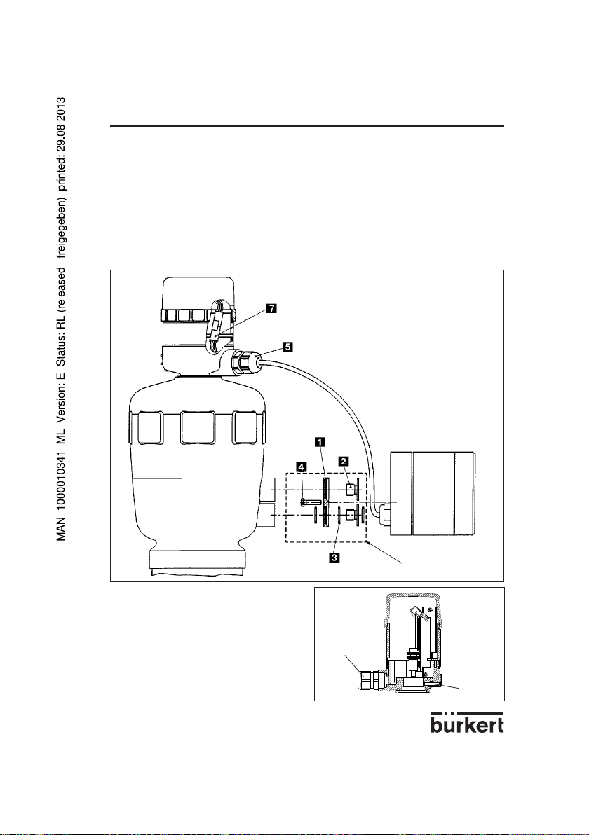
3.1.1 Anbau des Positioners an ein Stetigventil mit Membranantrieb (nach NAMUR)
Anordnung
Bei einem Stetigventil mit Membranantrieb ist die Gerätevariante 1 mit dem geräteinternen Wegmeßsystem (Drehpotentiometer) zu verwenden. Der Positioner wird an die sogenannte Laterne des Membranantriebs angeschraubt (Abb. 7). Die Übertragung der Ventilstellung auf das interne Wegmeßsystem
erfolgt über einen Hebel nach NAMUR (Abb. 8).
Abb. 7 Anbau an ein Stetigventil mit Mem-
branantrieb 265
Montage
Für die Montage der Gerätevariante 1 des Positioners an ein Stetigventil mit Membranantrieb (z. B.
265) ist ein Anbauwinkel vorgesehen (Abb. 10). Es sind folgende Schritte auszuführen:
Anbauwinkel "1" mit 4 Schrauben M6 "10" an den Positioner anschrauben.
Stift "2" mit Scheibe "7" und Mutter "8" an der Stelle des Hebels "4" befestigen, die dem gewünschten
Hub entspricht (Markierung auf dem Hebel in mm Hub).
Um einen "TURN POT" Fehler (Unempfindlichkeitsbereich des Wegsensors) zu vermeiden, die Welle
des Positionerwegsensors so einrichten, dass die Abflachung, während des ganzen Antriebhubs, nie
vor der gelben Marke vorbei geht (siehe folgende Abb.).
Abb. 8 Rückansicht des Positioners (Geräte-
variante 1) mit Hebel
Abflachung auf der
Wegsensorwelle
Hebel "4" mit Stift auf die Wegsensorwelle des Positioners aufstecken. Anschließend Hebel mit
Schraube "9" festschrauben.
Mitnehmer "3" mit Zylinderschrauben "6" an der Hub-Stange des Membranventils befestigen.
D-10-
Gelbe Marke
Page 11
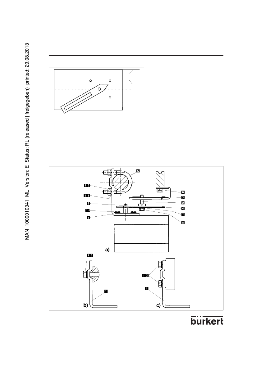
3 INSTALLATION
Abb. 9 Stellung des Hebels bei der Montage
Parallel
Positioner mit dem angeschraubten Anbauwinkel "1" so an den Membranantrieb ansetzen, daß der Stift
"2" in den Mitnehmer "3" eingreift, die Spitze des Hebels parallel zur Oberseite des Positioners steht
(Abb. 9) und die Rückseite des Positioners parallel zum Mitnehmer "3" verläuft. In dieser Lage den
Positioner entsprechend der folgenden Variante am Membranantrieb befestigen:
- Bei Membranantrieben mit Pfeiler-Laternen Anbauwinkel "1" mit 2 U-Bolzen "5" und Muttern "13"
sowie Scheiben "12" an der betreffenden Pfeiler-Laterne befestigen (Abb. 10a).
- Bei Membranantrieben mit Guß-Laternen Anbauwinkel "1" mit einer Schraube "13" (Abb. 10 b) bzw.
vier Schrauben "13" (Abb. 10c) an der betreffenden Guß-Laterne befestigen.
Abb. 10 Montage des Positioners an ein Stetigventil mit Membranantrieb
POSITIONER 1067
D-11-
Page 12

3 INSTALLATION
3.1.2 Anbau des Positioners an ein Stetigventil mit Kolbenantrieb
Anordnung
Bei einem Stetigventil mit Kolbenantrieb ist die Gerätevariante 2 des Positioners mit dem externen
Wegmeßsystem (siehe Abb. 14) zu verwenden, das auf das Ventil aufgesteckt und aufgeschraubt wird
(Abb. 11). Die Übertragung der Stellung des Kolbens erfolgt auf direkte Weise über die mit einer Feder
versehene Stange des Wegmeßsystems (Linearpotentiometer).
Abb. 11 Anbau an Stetigventil mit Kolbenan-
trieb 2731
Montage
Montage der Gerätevariante 2 des Positioners an ein Stetigventil mit Kolbenantrieb
Für die Montage der Gerätevariante 2 des Positioners an ein Kolbenventil
(z. B. 2731) ist ein Anbauteile-Satz (Adapter NAMUR) vorgesehen (Abb. 13), der aus einer Anbauplatte "1", zwei Hohlschrauben "2", drei O-Ringen "3" und zwei Zylinderschrauben M5 "4" besteht.
Bei der Montage des Positioners Variante 2 an ein Stetigventil mit Kolbenantrieb sind folgende Schritte
auszuführen (Abb. 13):
Einen O-Ring "3" in Senkung der Anbauplatte "1" (Antriebsseite) einlegen. Bei großer Ausführung zweiten O-Ring auf der anderen Seite der Anbauplatte einfügen.
Zwei Zylinderschrauben M5 "4" von der Antriebsseite durch die Bohrungen ø 5mm der Anbauplatte
stecken.
Die vormontierte Anbauplatte "1" mit zwei Hohlschrauben "2" so an die beiden Stutzen des Ventilantriebs anschrauben, daß der untere Stutzen mit dem O-Ring abgedichtet ist.
Einen O-Ring "3" in die Nut auf der Rückseite des Positioners einlegen.
Positioner an Anbauplatte anfügen und mit den beiden Zylinderschrauben "4" anschrauben.
Abb. 12 Rückansicht des Positioners (Gerä-
tevariante 2)
POSITIONER 1067
D-12-
Page 13
3 INSTALLATION
Montage des externen Wegmeßsystems: siehe Montage-Hinweise auf Seiten D14 und D15:
- Führen Sie Schritte a) bis g) Seite D14 aus (siehe auch Abb. 17)
- Führen Sie das Positionerkabel "7" durch die Kabeldurchführung "5" des Wegmessystems durch
(siehe Abb. 13 und 14)
- Führen Sie Schritte l) und m) Seite D14 aus (siehe auch Abb. 17).
Abb. 13 Schema zur Montage von Positioner Variante 2 und externem Wegmeßsystem an ein
Stetigventil mit Kolbenantrieb (Adapter nach NAMUR)
POSITIONER 1067
Abb. 14 Externes Wegmeßsystem
D-13-
Anbauteile-Satz für Bürkert
Kolbenantriebe (ø125)
5
6
Page 14

POSITIONER 10673 INSTALLATION
3.1.3 Aufbau des Positioners (Variante 3, getrennte Ausführung) für ein Stetigventil mit
Kolbenantrieb
Anordnung
Bei einem Stetigventil mit Kolbenantrieb ist die Gerätevariante 3 des Positioners mit dem externen
Wegmeßsystem (siehe Abb. 14) zu verwenden, das auf das Ventil aufgesteckt und aufgeschraubt wird
(Abb. 15). Die Übertragung der Stellung des Kolbens erfolgt auf direkte Weise über die mit einer Feder
versehene Stange des Wegmeßsystems (Linearpotentiometer).
Abb. 15 Stetigventil mit Kolbenantrieb und
Positioner Variante 3
Montage
Die Gerätevariante 3 des Positioners wird an eine DIN-Schiene angebaut.
Montage des externen Wegmeßsystems (siehe Abb. 17):
a) Überprüfen, ob im Ventilantrieb oben ein O-Ring eingelegt ist. Erforderlichenfalls O-Ring "6"
einfügen.
b) Befestigungsschraube "3" aufschrauben.
c) Den Kunststoffring "4" auf das obere Teil des Ventilantriebs 5 aufsetzen (nur bei
Größen 100 und 125) dann das externe Wegmessystem aufstecken (Abb.14).
d) Befestigungsschraube "3" anschrauben.
e) Gehäuse "11" des Wegmessystems aufschrauben.
f) Vergewissern Sie sich, dass das Kabel des Potentiometers den Weg der Wegmesstange nicht
behindert, indem es hinter den Potentiometer angebracht wird.
Potentiometer
Kabel
Abb. 16 Rückansicht des Positioners - An-
bau an DIN-Schiene
Schlitz für die
Elektronikplatine
D-14-
Page 15

3 INSTALLATION
+
-
A
1
2
4
5
6
7
8
12
3
9
10
11
g) Den Schleifer des Potentiometers in die Rille "9" der Wegmesstange "8" einfügen und die
Wegmesstange auf die Antriebsstange aufsetzen. Schraube "10" festschrauben.
h) Die Elektronikplatine "2" in die Nut des Positionergehäuses einsetzen.
i) Den Potentiometerstecker "1" innerhalb des Gehäuses an den Stecker der Elektronikplatine
farbengemäß anschließen (blaue Nut).
j) Das Positionerkabel "12" an der gewünschten Länge abschneiden und es durch die
Kabeldurchführung "7" des Wegmessystems durchführen.
k) Das kabel "12" gemäß folgender Steckeranschlüsse an den Stecker der Elektronikplatine
anschließen:
- : braun
A : weiß
+ : grün
l) Die Kabeldurchführung "7" festschrauben.
m) Das Gehäuse "11" des Wegmessystems wieder festschrauben.
POSITIONER 1067
Abb. 17 Schema zur Montage von Positioner Variante 3 und externem Wegmeßsystem
D-15-
Page 16

3 INSTALLATION
3.1.4 Anbau des Positioners an ein Stetigventil mit Drehantrieb
Hinweis: Bei Anbau eines 1067 an einen dopplewirkenden Antrieb wählen Sie für Regelaufgaben die
Dimensionierung der Antriebsgröße eine Dimension größer als die nach der Drehmomentauslegung
erforderliche. Der pneumatische Arbeitsanschluss A1 ist mit der Antriebskammer zu verbinden, deren
Axe im Belüftungsfsfall eine Rechtsdrehung (im Uhrzeigersinn) bewirkt.
Anordnung
Bei einem Stetigventil mit Dreh- bzw. Schwenkantrieb ist die Gerätevariante 1 des Positioners mit
geräteinternem Wegmeßsystem zu verwenden, dessen Welle an den Drehantrieb des Ventils (z. B.
Klappenventil) angekuppelt wird. Die Stellung des Drehantriebs wird also direkt auf die Welle des Wegmeßsystems übertragen.
Abb. 18 Anbau an ein Stetigventil mit Dreh-
antrieb
Montage
Für die Montage der Gerätevariante 1 des Positioners an ein Stetigventil mit Dreh- bzw. Schwenkantrieb (z. B. 3210) ist eine Kupplung (Adapter) "1" vorgesehen (Abb. 20). Außerdem wird ein Montagebügel "3" benötigt (Abb. 21), der vom Hersteller des Schwenkantriebes bezogen werden kann (er dient
normalerweise zur Montage eines Endschalterkastens).
Bei der Montage sind folgende Schritte auszuführen (Abb. 21):
Befestigung des Montagebügels "3" am Ventilantrieb.
Aufstecken der Kupplung "1" auf die Welle des Wegmeßsystems des Positioners. Der Gewindestift "2"
an der Kupplung ist vorher etwas herauszudrehen.
Aufsetzen des Positioners auf den Montagebügel. Dabei ist darauf zu achten, daß das Flachstück der
Kupplung in den Schlitz des Wellenendes des Antriebs eingreift.
Befestigung des Positioners am Montagebügel mit 4 Schrauben M6.
Fixieren der Kupplung auf der Welle des Wegmeßsystems durch Eindrehen des Gewindestiftes "2".
Wird nach dem Start der Funktion AUTOTUNE im LCD-Display die Meldung TURN POT angezeigt, so
muß der Gewindestift gelöst und die Welle des Wegmeßsystems relativ zum Antrieb um 180° gedreht
werden. Danach ist der Gewindestift wieder festzuziehen und die Funktion AUTOTUNE zu wiederholen.
Abb. 19 Rückseite des Positioners (Geräte-
variante 1) mit Befestigungslöchern
POSITIONER 1067
D-16-
Page 17
POSITIONER 10673 INSTALLATION
Abb. 20 Kupplung für Stetigventil mit Drehantrieb
Abb. 21 Montage des Positioners an ein
Stetigventil mit Drehantrieb
Stetigventil mit Drehantrieb
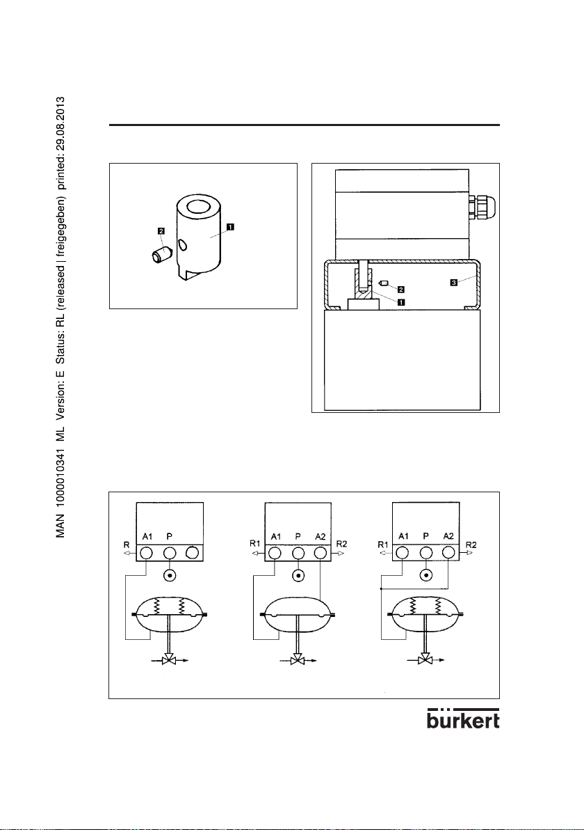
3.2 Fluidische Anschlüsse
Den Druckanschluß P mit dem Versorgungsdruck (6 bar max.) verbinden, bevor die Versorgungsspannung angelegt wird
Abb. 22 Anschlußbelegung am Beispiel von Membranantrieben
Einfachwirkend Doppeltwirkend Einfachwirkend, parallel
(für höheren Durchfluß)
D-17-
Page 18

POSITIONER 10673 INSTALLATION
3.3 Elektrische Anschlüsse
Abb. 23 Anschlußbelegung
Jumperposition
Eingang U1 (Einheitssignal 0 ... 10 V): Eingangswiderstand 200 kΩ
Eingang I1 (Einheitssignal 0/4 ... 20mA): Eingangswiderstand < 175 Ω
Eingang I2 (Einheitssignal 4 ... 20mA): Eingangswiderstand < 175 Ω
Signal Eingang :
- entweder für
Stellungssollwert (Betrieb als
Stellungsregler)
- oder für Prozeßsollwert
(Betrieb als Prozeßregler)
- Eingang für
Prozeßistwert
Binäreingang
Kontakt
Ausgang
(Option)
Versorgungsspannung
Achtung!: Zur Gewährleistung der elektromagnetischen Verträglichkeit (EMV) muß das M4Innengewinde der Armatur mit einem möglichst kurzen Kabel an die Erde gelegt werden.
M4-Innengewinde
D-18-
Page 19

4.1 Bedien- und Anzeigeelemente
POSITIONER 10674 BEDIENUNG
AUTOTUNE
LED
Taste "Pfeil oben"
Taste "Pfeil unten"
HAND/AUTOMATIK-Taste
4.2 Be benen
Für die Bedienung des Positioners sind die folgenden zwei Bedienebenen vorgesehen:
Prozeßbedienebene
In dieser Ebene, die sich nach jedem Einschalten des Gerätes einstellt, kann zwischen den Betriebszuständen HAND und AUTOMATIK umgeschaltet werden. Im Betriebszustand HAND läßt sich das Ventil
durch Betätigen der "Pfeiltasten" von Hand auf- bzw. zufahren.
Konfi gurierebene
Die Konfigurierebene dient dazu, die Grundfunktionen bei der ersten Inbetriebnahme zu spezifizieren
und bei Bedarf Zusatzfunktionen zu konfigurieren.
Nach jedem Einschalten der Betriebsspannung befindet sich der Positioner in der Ebene im Betriebszustand AUTOMATIK. Ein Wechsel in den Betriebszustand HAND ist über die HAND/AUTOMATIKTaste möglich (siehe § 4.4). Aus der Bedienebene kann durch Drücken der HAND/AUTOMATIK-Taste
über 5 Sekunden in die umgeschaltet werden.
D-19-
Page 20
POSITIONER 10674 BEDIENUNG
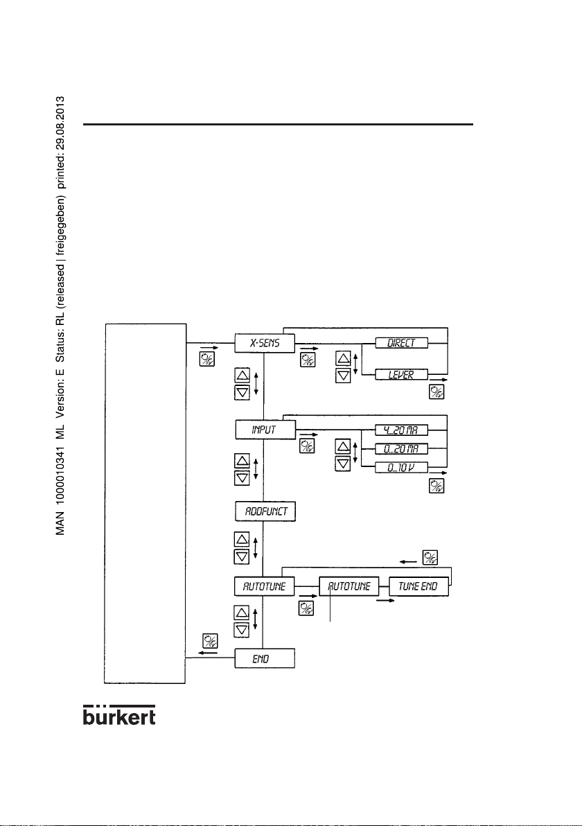
4.3 Inbetriebnahme
Bei der ersten Inbetriebnahme des Positioners im Zusammenhang mit einem bestimmten Ventil sind
folgende Grundeinstellungen vorzunehmen (Spezifizierung der Grundfunktionen):
- Angabe der Art der Stellungsrückmeldung vom Ventil zum Wegmeßsystem (direkt oder Hebelmechanismus),
- Angabe des für die Sollwertvorgabe gewählten Einheitssignaleingangs (0 ... 20 mA, 4 ... 20 mA oder
0 ... 10 V),
- Auslösen der automatischen Anpassung des Stellungsreglers an das verwendete Ventil.
Beim Einschalten der Betriebsspannung befindet sich der Positioner in der Prozeßbedienebene. Zur
Spezifizierung der Grundfunktionen ist in die Konfigurierebene umzuschalten. Dazu ist die HAND/
AUTOMATIK-Taste 5 Sekunden lang zu drücken. Danach erscheint auf dem Display mit X-SENS der
erste Menüpunkt des Hauptmenüs.
Abb. 24 Hauptmenü für die Einstellungen bei der ersten Inbetriebnahme
Betriebszustand
AUTOMATIK
oder
HAND
nach ca. 30 bis 120 Sek.
BLINKT
D-20-
Page 21

POSITIONER 10674 BEDIENUNG
Zur Durchführung einer Einstellung innerhalb der Menüpunkte X-SENS und INPUT ist die HAND/AUTOMATIK-Taste erneut kurzzeitig zu drücken. Danach erscheint auf dem Display einer der Menüunterpunkte. Zwischen diesen Unterpunkten, die jeweils eine Enstellmöglichkeit beschreiben, kann wiederum
durch Betätigen der Pfeiltasten hin- und hergeschaltet werden. Die eigentliche Einstellung erfolgt
dadurch, daß bei dem ausgewählten Menüunterpunkt die HAND/AUTOMATIK-Taste gedrückt wird.
Abb. 25 Bedeutung der Menüpunkte im Hauptmenü
Grundfunktion Zugehörige Einstellungen
X-SENS Art der Informationsübertragung zwischen Stellglied und Wegmeßsystem
(ab Werk auf DIRECT eingestellt)
- DIRECT - Linearer Zusammenhang
- LEVER - Sinusförmiger Zusammenhang (Verwendung eines Hebels)
INPUT Angabe des gewählten Einheitssignals
- 4 ... 20 MA - Einheitssignal Strom 4 ... 20 mA
- 0 ... 20 MA - Einheitssignal Strom 0 ... 20 mA
- 0 ... 10 V - Einheitssignal Spannung 0 ... 10 V
ADDFUNCT Konfigurieren von Zusatzfunktionen
AUTOTUNE Auslösen der automatischen Anpassung des Stellungsreglers an das Ventil
END Menüende
Bei dem Menüpunkt X-SENS geht es darum anzugeben, ob der mechanischen Übertragung der Weginformation von der Stelleinrichtung zum Wegmeßsystem ein linearer oder ein sinusförmiger Zusammenhang zugrunde liegt. Ein sinusförmiger Zusammenhang ergibt sich dann, wenn zur Übertragung
der Weginformation der Hebelmechanismus (Hebel = Lever) verwendet wird (vergl. Abschn. 3.1.1). In
diesem Fall erfolgt nach Bestätigung von LEVER geräteintern eine Linearisierung über eine approximierte Sinusfunktion.
Der Menüpunkt ADDFUNCT kann bei der ersten Inbetriebnahme übersprungen werden. Er dient zur
Konfigurierung von Zusatzfunktionen.
Über den Menüpunkt AUTOTUNE wird das Programm zur automatischen Parametrierung des Positioners gestartet. Dadurch werden selbsttätig die folgenden Funktionen ausgelöst:
- Anpassung des Sensorsignals an den (physikalischen) Hub des verwendeten Schrägsitzventils,
- Ermittlung von Parametern der PWM-Signale zur Ansteuerung der internen Magnetventile,
- Optimale Einstellung der Reglerparameter des Stellungsreglers (Zielfunktion: Möglichst schnelles und
überschwingungsfreies Anfahren der Soll-Position).
Der Start des Programms zur automatischen Parametrierung erfolgt dadurch, daß im Hauptmenü der
Menüpunkt AUTOTUNE eingestellt und die HAND/AUTOMATIK-Taste 5 Sekunden lang gedrückt wird.
Auf dem Display erscheint TUNE mit einem Countdown von 5 auf 0. Danach blinkt das Wort AUTOTUNE ca 30 bis 120 Sekunden (je nach Antriebsvolumen). Die automatische Parametrierung ist beendet,
nachdem TUNE END im Display erscheint.
Bemerkung:Bei Komplettlieferung eines Prozeßventiles mit angebautem Positioner wurde bereits im
Werk die AUTOTUNE-Funktion durchgeführt. Es ist jedoch empfehlenswert diese noch einmal unter
den vorliegenden Einsatzbedingungen zu wiederholen, um eine optimale Parametrierung des Positio-
D-21-
Page 22

4 BEDIENUNG
ners zu erhalten.
Kann die AUTOTUNE-Routine nicht vollständig ausgeführt werden, wird im Display eine Fehlermeldung
angezeigt (siehe Liste der Fehlermeldungen in Abschnitt 5).
Soll das Hauptmenü für die Einstellungen bei der Inbetriebnahme wieder verlassen werden, ist zunächst
durch Betätigen der Pfeiltasten der Menüpunkt END auszuwählen. Nach Drücken der HAND/AUTOMATIK-Taste befindet sich das Gerät dann wieder im Betriebszustand, indem es sich vor dem Umschalten
in das Hauptmenü befand (HAND oder AUTOMATIK).
POSITIONER 1067
4.4 Prozeßbedienen
4.4.1 Bedeutung der LED und der Tasten in der Ebene
LED Grüne LED in der HAND/AUTOMATIK-Taste leuchtet: Betriebszustand AUTOMATIK
Grüne LED in der HAND/AUTOMATIK-Taste ist aus: Betriebszustand HAND
Tasten
- Betätigen der HAND/AUTOMATIK-Taste (Tastendruck kürzer als 5 Sekunden): Umschalten zwischen
Betriebszustand HAND und AUTOMATIK.
- Drücken der HAND/AUTOMATIK-Taste (Tastendruck länger als 5 s): Einstieg in das Konfiguriermenü.
- Betätigen der Pfeiltasten im Betriebszustand AUTOMATIK bei konfigurierter Zusatzfunktion PCONTRL
SETPOINT INTERN und eingestellter Anzeige SP (Tastendruck länger als 3 Sekunden): Verändern
des Prozeßsollwertes (siehe Abschn.)
- Betätigen der Pfeiltasten im Betriebszustand AUTOMATIK: Umschalten der Anzeige.
- Drücken der Taste "Pfeil oben" im Betriebszustand HAND: Auffahren des Antriebs.
- Drücken der Taste "Pfeil unten" im Betriebszustand HAND: Zufahren des Antriebs.
4.4.2 Anzeigemöglichkeiten
Anzeigen im Betriebszustand AUTOMATIK
Prozeßregler nicht aktiv
Bezüglich des Stellungsreglers sind folgende Anzeigen möglich:
Ist-Position des Ventilantriebs: XPOS___ (0...100%)
Soll-Position des Ventilantriebs: WPOS___ (0...100%)
Durch Betätigen der "Pfeiltasten" kann zwischen diesen Anzeigen umgeschaltet werden.
Prozeßregler aktiv
Wenn der Prozeßregler aktiv ist, können folgende Größen angezeigt werden:
Istwert der Prozeßgröße (Prozeßistwert): PV____ (-99.9 ... 999.9)
Sollwert der Prozeßgröße (Prozeßsollwert): SP____ (-99.9 ... 999.9)
Ist-Position des Ventilantriebs: XPOS___ (0...100%)
Soll-Position des Ventilantriebs: WPOS___ (0...100%)
Durch Betätigen der "Pfeiltasten" kann zwischen diesen vier Anzeigen umgeschaltet werden. Die Taste
"Pfeil unten" bewirkt ein "Durchblättern" der angezeigten Größen in der oben angegebenen Reihenfolge.
Wurde beim Konfigurieren die Zusatzfunktion PCONTRL SETPOINT INTERN (Einstellen des Sollwertes über Tasten) spezifiziert, dann kann bei eingestellter Anzeige SP (Setpoint) durch Betätigen einer
der beiden Pfeiltasten von länger als 3 Sekunden der Modus zum Verändern des Prozeßsollwertes
aktiviert werden. Wenn nach dieser Zeit die Taste wieder losgelassen wird, blinkt die erste Stelle des
Prozeßsollwertes. Durch erneutes Drücken der Pfeiltasten kann nun die Einstellung dieser Stelle vorgenommen werden. Nach Bestätigung durch die HAND/AUTOMATIK-Taste wird der eingestellte Wert
übernommen. In gleicher Weise kann dann mit den übrigen Stellen verfahren werden. Nach Bestäti-
D-22-
Page 23
4 BEDIENUNG
POSITIONER 1067
gung der vierten Stelle erfolgt der Rücksprung.
Anzeigen im Betriebszustand HAND
Prozeßregler nicht aktiv
Es wird die Ist-Position des Antriebs angezeigt: XPOS___ (0...100%)
Prozeßregler aktiv
Wenn im Betriebszustand HAND keine Bedienhandlungen durchgeführt werden, wird ständig der
Istwert der Prozeßgröße angezeigt: PV____ (-99.9 ... 999.9)
Werden zur Handbetätigung des Ventils die Pfeiltasten gedrückt (vergl. Abschn. ), dann wird die IstPosition angezeigt: XPOS___ (0...100%)
Sobald die Tasten nicht mehr gedrückt sind, erscheint wieder die Anzeige des Prozeßistwertes PV.
Das Umschalten zwischen den Betriebszuständen HAND und AUTOMATIK erfolgt durch Betätigen der
HAND/AUTOMATIK-Taste.
Wird im Betriebszustand HAND die Taste "Pfeil oben" gedrückt, dann wird das Stetigventil über den
Antrieb kontinuierlich aufgefahren. Nach Loslassen der Taste wird dieser Vorgang unterbrochen, und
das Ventil bleibt in der eingenommenen Stellung stehen. Durch Drücken der Taste "Pfeil unten" wird
das Ventil in entsprechender Weise zugefahren.
Wird nach Drücken einer Pfeiltaste zusätzlich noch die andere Pfeiltaste gedrückt, so fährt das Ventil im
Schnellgang in die Richtung, die durch die zuerst betätigten Taste vorgegeben wurde.
Sowohl im Betriebszustand HAND als auch im Betriebszustand AUTOMATIK kann durch Drücken der
HAND/AUTOMATIK-Taste über 5 Sekunden in die Konfigurierebene umgeschaltet werden. Beim Zurückschalten in die Prozeßbedienebene wird der Betriebszustand eingenommen, der vor dem Umschalten eingestellt war.
Abb. 26 Bedienstruktur und Bedienabläufe
Anzeige
umschalten
Antrieb zu,
Normalgang
/
Antrieb zu,
Schnellgang
Taste drücken
Taste loslasse
/
V
V
/
/
/
V
Betriebszustand
HAND
Konfi gurieren
Keine
Bedienhandlung
Keine
Bedienhandlung
(>5s)
Konfi gurieren
END
D-23-
(>5s)
SP
V
END
V
Zwei Tasten gleichzeitig drücken
V
Eine von zwei Tasten drücken
Betriebszustand
AUTOMATIK
Prozeßsollwert
einstellen
(>3s)
/
Antrieb auf,
Normalgang
V
Antrieb auf,
Schnellgang
/
Page 24

POSITIONER 10674 BEDIENUNG
4.5 Konfigurieren
4.5.1 Zusatzfunktionen
Das Bedienkonzept für den Positioner basiert auf einer strikten Trennung zwischen Grund- und
Zusatzfunktionen. Im Auslieferungszustand des Gerätes sind nur die Grundfunktionen aktiviert. Sie
dienen dazu, bei der Erstinbetriebnahme gerätespezifische Grundeinstellungen vorzunehmen (cf §.
4.3). Sie sind für einen normalen Betrieb ausreichend. Für anspruchsvollere Aufgaben der Stellungs-
und Prozeßregelung können in der Konfigurierebene vorkonfektionierte Zusatzfunktionen ausgewählt
und spezifiziert werden. Diese Zusatzfunktionen sind hier anschließend aufgelistet. Eine ausführlichere
Erläuterung erfolgt im § 4.5.4.
Abb. 27 Zusammenstellung der Zusatzfunktionen
Zusatzfunktion Parameter Kurzbeschreibung
ACTUATE Wirkungsweise des Antriebs
- SINGLE
INTERN - Antrieb einfach wirkend, mit internen oder ohne Boost-Ventilen
BOOST - Antrieb einfach wirkend, mit externen Boost-Ventilen
- DOUBLE - Antrieb doppelt wirkend
CHARACT Auswahl der Übertragungskennlinie zwischen Eingangssignal
und Hub (Korrekturkennlinie).
- LINEAR - Lineare Kennlinie
- 1 : 25 - Gleichprozentige Kennlinie mit Stellverhältnis 1 : 25
- 1 : 50 - Gleichprozentige Kennlinie mit Stellverhältnis 1 : 50
- 25 : 1 - Invers gleichprozentige Kennlinie mit Stellverh. 25 : 1
- 50 :1 - Invers gleichprozentige Kennlinie mit Stellverh. 50 : 1
- FREE - Benutzerdefinierte, frei programmierbare Kennlinie.
DEADBND - DBD Unempfindlichkeisbereich bezüglich der Regeldifferenz des
Stellungsreglers
CLTIGHT - CLT - Dichtschließschwelle
DIRECTN -WPOS Wirksinn zwischen Eingangssignal und Sollposition.
RISE - Direkte (positive) Wirkrichtung
FALL - Inverse (negative) Wirkrichtung
-XPOS Zuordnung vom Belüftungszustand der Antriebskammer A1 zur
Istposition.
RISE - Direkte (positive) Wirkrichtung
FALL - Inverse (negative) Wirkrichtung
SPLTRNG Signalbereichsaufteilung. Eingangssignal in %, für den das Ventil
den gesamten Hubbereich durchläuft.
- MIN - Eingabe des minimalen Wertes des Eingangssignals.
- MAX - Eingabe des maximalen Wertes des Eingangssignals.
X-LIMIT Begrenzung des mechanischen Hubbereichs.
- XMIN - Eingabe des Anfangswertes des Hubbereichs in %.
- XMAX - Eingabe des Endwertes des Hubbereichs in %.
X-TIME Stellgeschwindigkeitsbegrenzung
- OPN FAST - Maximale Stellgeschw. beim Öffnen
- OPN SLOW - Begrenzung der Stellgeschwindigkeit beim Öffnen
- CLS FAST - Maximale Stellgeschw. beim Schließen
- CLS SLOW - Begrenzung der Stellgeschwindigkeit beim Schließen
D-24-
Page 25

POSITIONER 10674 BEDIENUNG
Zusatzfunktion Parameter Kurzbeschreibung
PCONTROL Prozeßreglerkonfiguration
- SETPOINT -Art der Sollwertvorgabe
INTERN Interne Sollwertvorgabe über Tastatur
EXTERN Externe Sollwertvorgabe über Einheitssignal
- PARAM - Parameter des Prozeßreglers
KP Verstärkungsfaktor
TN Nachstellzeit
TV Vorhaltezeit
X0 Arbeitspunkt des P-Reglers
DBD Unempfindlichkeitsbereich des P-Reglers
- SCALE - Skalierung der Eingänge von Prozeßistwert u. -sollwert.
DP Position des Dezimalpunkts der Skalierung.
PV-L Unterer Skalierungswert des Prozeßistwerts
PV-H Oberer Skalierungswert des Prozeßistwerts
SP-L Unterer Skalierungswert des Prozeßsollwerts
SP-H Oberer Skalierungswert des Prozeßsollwerts
BIN-IN Wirkungsweise des Binäreingangs.
- INACTIVE - Binäreingang inaktiv
- SAFEPOS - Sicherheitsposition
SPOS Position in %
- NORM OPN - Binäreingang offen, wenn nicht aktiv (Schließer)
- NORM CLS - Binäreingang geschlossen, wenn nicht aktiv (Öffner)
OUTPUT Konfiguration optionaler Ausgänge
- ANALOG - Analoge oder Prozess-Stellungsrückmeldung
- BINARY - Programmierbare Binärausgange
XDO Regelabweichungsalarm
XD Grenzwert für zulässige Regelabweichung
NORM OPN Binärausgang in Ruhestellung offen
NORM CLS Binärausgang in Ruhestellung geschlossen
BOOST - Signalausgang für externe Boosterventile
CODE - CODE - 4-Stelliger Benutzercode
MENU+M/A Code-Schutz aller Bedienhandlungen
MENU Code-Schutz des Konfigurationsmenü
D-25-
Page 26

4 BEDIENUNG
POSITIONER 1067
4.5.2 Konfi guriermenü
Das Konfiguriermenü kann aus der Bedienebene Prozeßbedienen heraus aktiviert werden, indem die HAND/AUTOMATIK-Taste 5 Sekunden lang gedrückt wird. Es besteht aus einem Haupt- und einem Zusatzmenü. Das Hauptmenü enthält zunächst die Grundfunktionen, die bei der Erstinbetriebnahme zu spezifizieren sind (siehe §4.3). Das
Zusatzmenü umfaßt die wählbaren Zusatzfunktionen. Es ist über den Menüpunkt ADDFUNCT des Hauptmenüs
erreichbar. Eine Spezifizierung von Gerätefunktionen und -parametern ist nur innerhalb des Hauptmenüs möglich.
Bei Bedarf läßt sich aber das Hauptmenü um Zusatzfunktionen aus dem Zusatzmenü erweitern, die dann ebenfalls
spezifiziert werden können.
Das folgende Bild veranschaulicht das Prinzip der Aufnahme von Menüpunkten des Zusatzmenüs in das Hauptmenü. Zunächst ist im Hauptmenü der Menüpunkt ADDFUNCT auszuwählen. Von hier aus gelangt man durch Betätigen der HAND/AUTOMATIK-Taste in das Zusatzmenü. Dort wird durch Betätigen der Tasten "Pfeil oben" bzw.
"Pfeil unten" eine gewünschte Zusatzfunktion eingestellt. Wird diese Zusatzfunktion durch Drücken der HAND/
AUTOMATIK-Taste bestätigt, dann wird sie automatisch mit einem Stern (*) gekennzeichnet. Alle so markierten
Funktionen werden nach Bestätigung von ENDFUNCT in das Hauptmenü übernommen, und sind dadurch automatisch aktiv. In dem auf diese Weise erweiterten Hauptmenü können nun die Zusatzfunktionen parametriert werden.
Abb. 28 Prinzip der Aufnahme von Zusatzfunktionen in das Hauptmenü
Auswahl des
Menüpunktes
ADDFUNCT
Hauptmenü
Bestätigung des
ausgewählten
Menüpunktes
Zustatzmenü
Rückkehr zum erweiterten
Hauptmenü
Erweitertes
Hauptmenü
Bestätigung der ausgewählten
Zusatzfunktionen zwecks
Aufnahme in das Hauptmenü
Sollen aufgenommene Zusatzfunktionen aus dem Hauptmenü entfernt werden, dann ist im Hauptmenü wieder
die Funktion ADDFUNCT auszuwählen und durch anschließendes Drücken der HAND/AUTOMATIK-Taste in
das Zusatzmenü umzuschalten. Wird nun eine durch einen Stern (*) gekennzeichnete Zusatzfunktion ausgewählt
und durch Drücken der HAND/AUTOMATIK-Taste bestätigt, dann wird sie aus dem Hauptmenü entfernt, und ist
deaktiviert.
In Abb. 26 ist das gesamte Konfiguriermenü mit allen Grund- und Zusatzfunktionen dargestellt. Das Weiterschalten
in senkrechter Richtung erfolgt durch entsprechende Betätigung der Pfeiltasten. Zur Bewegung in waagerechter
Richtung ist die HAND/AUTOMATIK-Taste zu drücken. Das Einstellen von Zahlenwerten in den dafür vorgesehenen
Menüpunkten erfolgt durch ein- oder mehrmaliges Betätigen der Tasten "Pfeil oben" (Vergrößern des Zahlenwertes) oder "Pfeil unten" (Verkleinern des Zahlenwertes). Bei vierstelligen Zahlen kann nur die blinkende Stelle mit
den "Pfeiltasten" eingestellt werden.
Durch Betätigen der HAND/AUTOMATIK-Taste wird zur jeweils nächsten Stelle umgeschaltet.
D-26-
Page 27

4 BEDIENUNG
X-SENS DIRECT
LEVER
INPUT
4...20MA
0...20MA
0...10V
ACTUATE
DOUBLE
CHARACT LINEAR
1/25
1/50
25/1
50/1
FREE
0 5 100
DEADBND DBD
CLTIGHT CLT
DIRECTN
WPOS
XPOS
END
RISE
FALL
RISE
FALL
SPLTRNG MIN
MAX
X-LIMIT X-MIN
X-MAX
PCONTRL SETPOINT
PARAM
SCALE
INTERN
EXTERN
KP
TN TV X0
X-TIME OPN FAST
OPN SLOW
CLS FAST
CLS SLOW
SINGLE INTERN
BOOST
END
DBD
PV-H SP-L SP-H
PV-L
DP
BIN-IN INACTIVE
SAFEPOS
SPOS NORM OPN
NORM CLS
ADDFUNCT
AUTOTUNE
END
A
OUTPUT
BINARY
CODE
ANALOG
NORM CLS
XD
XDO
NORM OPN
BOOST
CODE MENU+M/A
MENU
WPOS
XPOS
PV SP
Abb. 29 Komplettes Konfi guriermenü
POSITIONER 1067
D-27-
Page 28

POSITIONER 10674 BEDIENUNG
4.5.3 Bedeutung der Tasten in der Konfi gurierebene
Betätigen der Taste "Pfeil oben":
- Blättern im Menü nach oben (Auswahl).
- In einem ausgewählten und bestätigten Menüpunkt Inkrementieren (Vergrößern) von Zahlenwerten.
Betätigen der Taste "Pfeil unten":
- Blättern im Menü nach unten (Auswahl).
- In einem ausgewählten und bestätigten Menüpunkt Dekrementieren (Verkleinern) von Zahlenwerten.
Betätigen der HAND/AUTOMATIK-Taste innerhalb des Hauptmenüs:
- Bestätigung eines ausgewählten Menüpunktes.
- Bestätigung eingestellter Werte
Betätigen der HAND/AUTOMATIK-Taste innerhalb des Zusatzmenüs:
- Bestätigung eines ausgewählten Menüpunktes des Zusatzmenüs zur Aufnahme in das Hauptmenü.
Der ausgewählte Menüpunkt wird im Zusatzmenü mit einem Stern (*) gekennzeichnet. Der Menüpunkt
erscheint jetzt im Hauptmenü und kann dort ausgewählt und bearbeitet werden.
- Bestätigung eines ausgewählten, mit einem Stern gekennzeichneten Menüpunktes des Zusatzmenüs
zwecks Streichung aus dem Hauptmenü.
4.5.4 Erläuterungen zu den Grund- und Zusatzfunktionen
X-SENS (Werkseinstellung: DIRECT): Angabe der Art der Informationsübertragung zwischen Stetig-
ventil (Ventilstellung) und Wegmeß-System.
Optionen:
DIRECT: Es besteht ein linearer Zusammenhang zwischen der Ventilstellung und dem Ein-
gangssignal des Wegmeßsystems.
Beispiele:
Anbau des Positioners an ein Kolbenventil (z. B. 2731) und Verwendung des externen Wegmeßsystems (Linearpotentiometer) zur Messung der Kolbenstellung. Dabei wird die Linearbewegung des Kolbens in eine Linearbewegung des Potentiometers transformiert. Eine Kennlinienkorrektur ist demzufolge
nicht erforderlich.
Anbau des Positioners an ein Klappenventil mit Schwenkantrieb (z. B. 3210) und Verwendung des
internen Wegmeßsystems (Drehpotentiometer) zur Messung der Klappenstellung (siehe Abschn. 3.1.3
und Abb. 19). Die Drehbewegung der Klappe wird in eine dazu proportionale Drehbewegung des
Potentiometers umgeformt. Eine Kennlinienkorrektur ist nicht erforderlich.
LEVER: Es besteht ein sinusförmiger Zusammenhang zwischen der Ventilstellung und dem
Eingangssignal des Wegmeßsystems.
Beispiel:
Anbau des Positioners an ein Membranventil (z. B. 265) und Verwendung des internen Wegmeßsystems zur Messung der Ventilstellung (siehe Abschn. 3.1.1 und Abb. 7). Die Kopplung erfolgt über
einen Hebel (Lever) nach NAMUR. Die Linearbewegung der Membran wird in eine Drehbewegung des
Potentiometers transformiert. Dabei ergibt sich ein sinusförmiger Verlauf. Die Übertragungskennlinie
wird deshalb bei dieser Option geräteintern linearisiert.
INPUT (Werkseinstellung: 4 - 20 mA): Angabe des gewählten Einheitssignals.
Optionen:
4 - 20 mA: Verwendung des Einheitssignaleingangs 4 ... 20 mA
0 - 20 mA: Verwendung des Einheitssignaleingangs 0 ... 20 mA
0 - 10 V: Verwendung des Einheitssignaleingangs 0 ... 10 V
D-28-
Page 29
POSITIONER 10674 BEDIENUNG
ACTUATE (Werkseinstellung: SINGLE, INTERN): Wirkungsweise des verwendeten Ventilantriebs.
Optionen:
SINGLE, INTERN: Verwendung eines einfachwirkenden Antriebs mit internen oder ohne
Boost-Ventilen,
SINGLE, BOOST: Verwendung eines einfachwirkenden Antriebs mit externen Boost-Ventilen,
DOUBLE: Verwendung eines doppeltwirkenden Antriebs.
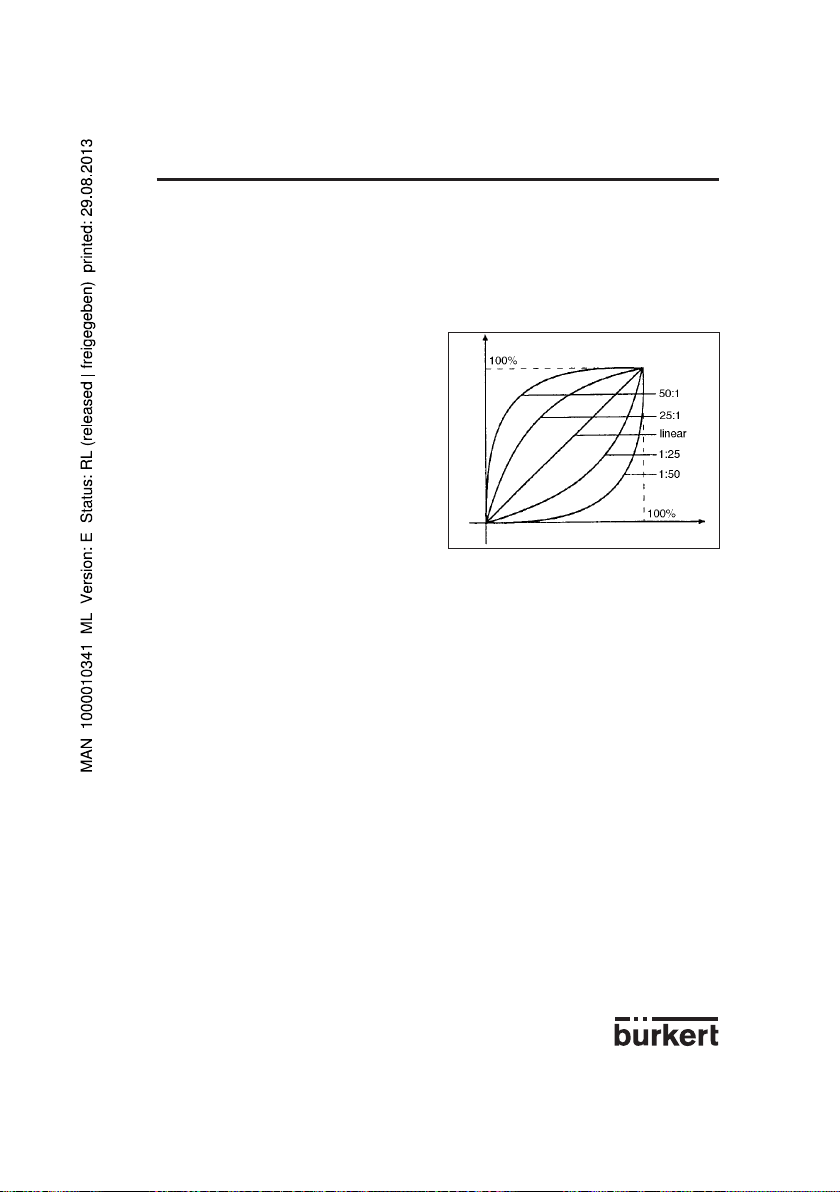
CHARACT (Werkseinstellung: LINEAR): Kundenspezifische Kennlinie (Characteristic).
Mit dieser Zusatzfunktion kann eine Übertragungskennlinie bezüglich Stellungs sollwert
(Soll-Position) und Ventilhub zur Korrektur der
Durchfluss- bzw. Betriebskennlinie ausgewählt
werden (Abb. 30).
Die Durchflußkennlinie kV = f(s) kennzeichnet den Durchfluß eines Ventils, ausgedrückt durch den
k
-Wert, in Abhängigkeit vom Hub s der Ventilspindel. Sie ist durch die Formgebung des Ventilkörpers
V
festgelegt. Man realisiert gewöhnlich zwei Typen von Durchflußkennlinien, die lineare und die gleichprozentige. Bei linearen Kennlinien sind gleichen Hubänderungen ds gleiche k
zugeordnet (dkV = n
gleichprozentige Änderung des kV-Wertes (dkv/kv=n
Die Betriebskennlinie Q = f(s) gibt den Zusammenhang zwischen dem Volumenstrom Q, der durch das
in eine Anlage eingebaute Ventil fließt, und dem Hub s wieder. In diese Kennlinie gehen die Eigenschaften der Rohrleitungen, Pumpen und Verbraucher ein. Sie weist deshalb eine gegenüber der Durchflußkennlinie abgewandelte Form auf.
Bei Stellaufgaben für Regelungen werden an den Verlauf der Betriebskennlinie meist besondere Anforderungen gestellt (z. B. Linearität). Aus diesem Grund macht es sich mitunter erforderlich, den Verlauf
der Betriebskennlinie in geeigneter Weise zu korrigieren. Dafür ist im Positioner ein Übertragungsglied
vorgesehen, das verschiedene Kennlinien realisiert, die zur Korrektur der Betriebskennlinie verwendet werden können. Es können eine lineare und verschiedene gleichprozentige Kennlinien mit einem
Stellverhältnis von 1:25, 1:50, 25:1 und 50:1 eingestellt werden (Abb. 30). Darüber hinaus ist es auch
möglich, eine Kennlinie über Stützstellen frei zu programmieren.
Optionen:
LINEAR Lineare Kennlinie
1:25 Gleichprozentige Kennlinie mit einem Stellverhältnis von 1:25.
1:50 Gleichprozentige Kennlinie mit einem Stellverhältnis von 1:50.
25:1 Invers gleichprozentige Kennlinie mit einem Stellverhältnis von 25:1.
50:1 Invers gleichprozentige Kennlinie mit einem Stellverhältnis von 50:1.
FREE Frei programmierbare Kennlinie auf der Basis vorzugebender Stützstellen.
ds). Bei einer gleichprozentigen Kennlinie entspricht einer Hubänderung ds eine
lin
Abb. 30 Korrekturkennlinien
Normierter Ventilhub
Normierter Stellungssollwert
-Wert-Änderungen dk
V
ds).
gleichpr
V
D-29-
Page 30

POSITIONER 10674 BEDIENUNG
Eingabe der frei programmierbaren Kennlinie
Die Kennlinie wird über 21 Stützstellen definiert, die gleichmäßig über den Stellungssollwertbereich von
0 ... 100 % verteilt sind. Ihr Abstand beträgt 5 %. Jeder Stützstelle kann ein frei wählbarer Hub (Einstellbereich: 0 ... 100 %) zugeordnet werden (Abb. 31). Die Differenz zwischen den Hubwerten zweier
benachbarter Stützstellen darf nicht größer als 20 % sein.
Zur Eingabe der Kennlinienpunkte (Funktionswerte) ist zunächst der Menü-Punkt FREE einzustellen.
Nach Betätigen der HAND/AUTOMATIK-Taste wird auf dem Display mit der Anzeige 0 (%) die erste
Stützstelle vorgegeben. Daneben steht als Funktionswert zunächst 0 (%). Mit den Pfeiltasten kann der
Funktionswert von 0 bis 100 % eingestellt werden. Nach Bestätigung mit der HAND/AUTOMATIKTaste wird die nächste Stützstelle auf dem Display angezeigt usw. Wird schließlich zur Bestätigung des
zur letzten Stützstelle (100 %) gehörenden Funktionswertes die HAND/AUTOMATIK-Taste gedrückt,
erfolgt das Rückschalten zum Menüpunkt CHARACT.
Die Abbildung 31 demonstriert ein Beispiel für die freie Programmierung einer Korrekturkennlinie.
D-30-
Page 31

Abb. 31 Beispiel einer zu programmierenden Kennlinie
Hub (%)
POSITIONER 10674 BEDIENUNG
Einheitssignal (%)
Stellungssollwert (%)
Ventilhub (%)
Eingabe mittels Pfeiltasten
Vorgegebene Stützstelle
D-31-
Page 32

POSITIONER 10674 BEDIENUNG
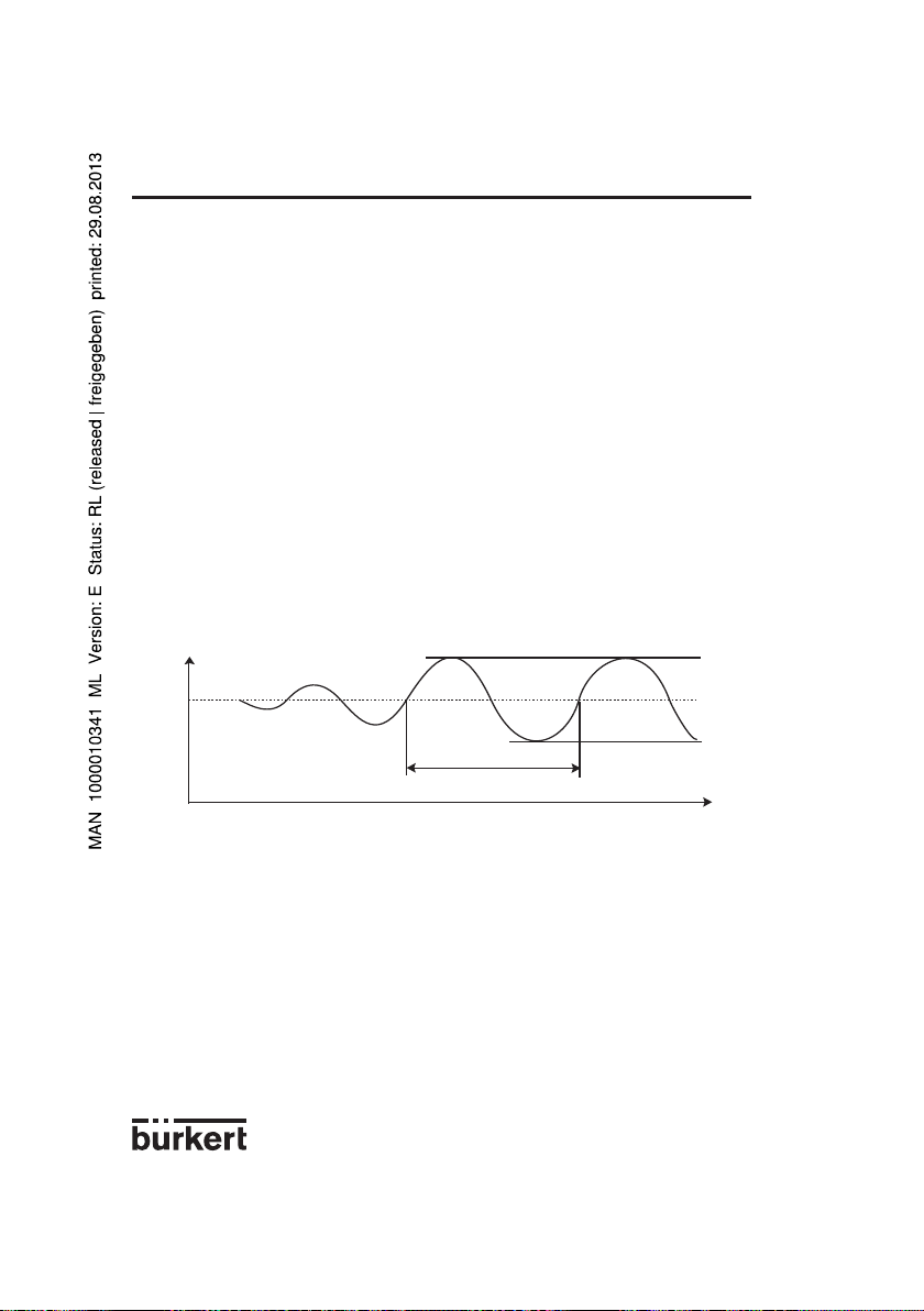
DEADBND (Werkseinstellung: DBD = 0,5 %): Totbereich (Deadband) der Regelabweichung des
Stellungsreglers
Durch die Zusatzfunktion DEADBND wird erreicht, daß der Stellungsregler erst ab einer bestimmten
Regeldifferenz |DBD| anspricht (Abb. 32). Dadurch wird das Stellventil "geschont".
Abb. 32 Totbereich DBD
Stellungssollwert
Regeldifferenz
Stellungsistwert
Zum Regler
Maximal 5%, bezogen auf den Hubbereich. Die untere Grenze wird durch AUTOTUNE ermittelt.
CLTIGHT (Werkseinstellung: CLT = 0,5 %): Dichtschließfunktion (Closed tight)
Die Dichtschließfunktion bewirkt, daß das Ventil außerhalb des Regelbereiches dicht schließt.
Abb. 33 Dichtschließfunktion
Hub (%)
CLT:Dichtschließschwelle.
Angabe eines Wertes (in %), ab dem der Antrieb vollständig entüftet (bei 0 %) bzw. belüftet (bei
100%) wird. Das Öffnen bzw. die Wiederaufnahme des Regelbetriebes erfolgt mit einer Hysterese von
1 % (siehe Abb. 33).
Einstellbereich:
0,0...10,0 % (gilt sowohl für vollständiges Enlüften als auch für vollständiges Belüften, siehe Abb. 33)
Einstellbar von 90,0 bis 100,0%
Sollwert (%)
Einstellbar von 0,0 bis 10,0%
D-32-
Page 33

POSITIONER 10674 BEDIENUNG
DIRECTN (Werkseinstellung: WPOS = RISE, XPOS = RISE): Wirksinn bzw. Wirkrichtung.
Über diese Zusatzfunktion kann durch den Parameter WPOS der Wirsinn zwischen Eingangssignal und
Sollposition (WPOS) und den Parameter XPOS die Zuordnung vonm Belüftungszustand der Antriebskammer A1 zur Istposition (XPOS) eingestellt werden.
Eingangssignal DIRECTN Zugeordnete
WPOS Sollposition
I1 U1 (WPOS)
0/4 mA 0 V RISE 0 %
20 mA 10 V 100 %
0/4 mA 0 V FALL 100 %
20 mA 10 V 0 %
Belüftungs- DIRECTN Zugeordnete
zustand XPOS Istposition
Kammer A1 (XPOS)
entlüftet RISE 0 %
belüftet 100 %
entlüftet FALL 100 %
belüftet 0 %
SPLTRNG (Werkseinstellung: MIN = 0%, MAX = 100%): Bereichsaufteilung (Split range)
Mit dieser Zusatzfunktion läßt sich der Sollwertbereich eines Positioners durch Festlegen eines minimalen und eines maximalen Wertes einschränken. Dadurch ist es möglich, einen genutzten Einheitssignalbereich (0 ...10 V, 0 ... 20 mA oder 4 ... 20 mA) auf mehrere Positioner aufzuteilen (ohne oder mit
Überlappung). Auf diese Weise können mehrere Ventile teilweise gleichzeitig oder nacheinander als
Stellglied genutzt werden (Abb. 35).
Abb. 35 Aufspalten eines Einheitssignalbereichs in zwei Sollwertbereiche
Hub (%)
Abb. 34 Wirkungssinn
0/4 mA Eingangssignal 20 mA
0 V 10 V
enlüftet belüftet
Belüftungzustand
RISE
FALL
RISE
FALL
Sollwertbereich
Der Mindestabstand zwischen MIN und MAX beträgt 25 %.
MIN: 0 ... 75 % des Einheitssignalbereichs,
MAX: 25 ... 100 % des Einheitssignalbereichs.
von Positioner 1
Sollwertbereich
von Positioner 2
D-33-
Sollwert (mA)
Page 34

POSITIONER 10674 BEDIENUNG
X-LIMIT (Werkseinstellung: XMIN = 0%, XMAX = 100%): Hubbegrenzung.
Mit dieser Zusatzfunktion kann der (physikalische) Hub auf vorgegebene %-Werte MIN und MAX
begrenzt werden (Abb. 36). Im AUTOMATIK-Betrieb wird der Hubbereich des begrenzten Hubes dann
gleich 100 % gesetzt. Bei HAND-Betrieb wird dagegen der physikalische Hub angezeigt. ( Es ist also
zu beachten, daß im AUTOMATIK- und im HAND-Betrieb ein begrenzter Hub unterschiedlich angezeigt
wird).
Begrenzter
Hub (%)
Abb. 36 Hubbegrenzung
Einstellbereich:
XMIN: 0 ... 50 % des Gesamthubes,
XMAX: 50 ... 100 % des Gesamthubes.
Der Mindestabstand zwischen XMIN und XMAX beträgt 50 %.
X-TIME (Werkseinstellung: OPN FAST, CLS FAST): Stellgeschwindigkeitsbegrenzung.
Optionen:
OPN FAST (open fast): Das Öffnen des Stellventils erfolgt mit maximaler Stellgeschwindigkeit.
OPN SLOW (open slow): Beim Öffnen des Stellventils wird die maximale Stellgeschwindigkeit
begrenzt.
CLS FAST (close fast): Das Schließen des Stellventils erfolgt mit maximaler Stellgeschwindig-
keit.
CLS SLOW (close slow): Beim Schließen des Stellventils wird die maximale Stellgeschwindig-
keit begrenzt.
PCONTRL (process control): Prozeßreglerkonfiguration.
SETPOINT (Werkseinstellung: EXTERN): Sollwertvorgabe
INTERN: Der Sollwert kann über die Pfeiltasten eingegeben werden (siehe §4.4.2).
EXTERN: Die Sollwertvorgabe erfolgt über den Einheitssignaleingang.
PARAM: Einstellen der Parameter des Prozeßreglers ( PID-Regler)
KP: (Proportionalbeiwert oder Verstärkung)
Einstellbereich: 0 ... 99,99 (Werkseinstellung: 1,00)
TN: (Nachstellzeit)
Einstellbereich: 0,5 ... 999,9 (Werkseinstellung: 999,9)
Physikalischer
Hub (%)
Unbegrenzter
Hub (%)
Begrenzter
Hub (%)
Sollwert (mA)
D-34-
Page 35

POSITIONER 10674 BEDIENUNG
TV: (Vorhaltzeit)
Einstellbereich: 0,0 ... 999,9 (Werkseinstellung: 0)
X0: (Arbeitspunkt des Prozeßreglers)
Einstellbereich: 0 ... 100% (Werkseinstellung: 0%)
DBD: Unempfindlichkeitsbereich der Regelabweichung des Prozeßreglers.
Einstellbereich: 0,2 ... 5% (Werkseinstellung: 0,5 %)
SCALE: Skalierung der Eingänge des Prozeßreglers.
DP: Position des Dezimalpunkts für die Skalierungswerte
Einstellbereich: 0 ... 3 (Werkseinstellung: 0)
PV-L: Unterer Skalierwert für den Prozeßistwert (process value). Er wird dem kleinsten
Einstellbereich: -99,9 ... 990,0 (Werkseinstellung: 0,0)
PV-H: Oberer Skalierwert für den Prozeßistwert (process value). Er wird dem größten
Einstellbereich: -90,0 ... 999,9 (Werkseinstellung: 100,0)
SP-L: Unterer Skalierwert für den Prozeßsollwert (setpoint). Er wird dem kleinsten
Einstellbereich: -99,9 ... 990,0 (Werkseinstellung: 0,0)
SP-H: Oberer Skalierwert für den Prozeßsollwert (setpoint). Er wird dem größten
Einstellbereich: -90,0 ... 999,9 (Werkseinstellung: 100,0)
Skalierungsbeispiel:
Prozeßistwert über Transmitter: 4 ... 20 mA entspricht 0 ... 10 l/min
Prozeßsollwert von SPS: 4 ... 20 mA entspricht 0 ... 8 l/min
Abb. 37 Skalierungsbeispiel
Strom- bzw. Spannungswert des Einheitssignals zugeordnet.
Strom- bzw. Spannungswert des Einheitssignals zugeordnet.
Strom- bzw. Spannungswert des Einheitssignals zugeordnet. (Gilt nur bei der Einstellung SETPOINT EXTERN)
Strom- bzw. Spannungswert des Einheitssignals zugeordnet. (Gilt nur bei der Einstellung SETPOINT EXTERN)
Mögliche Eingaben von Skalierwerten beim Ska-
Skalierwert (l/min)
Prozeßistwert
lierungsbeispiel:
Variante 1 Variante 2 Variante 3
PV-L 0 0 0
PV-H 1,0 10,0 100,0
SP-L 0 0 0
SP-H 0,8 8,0 80,0
Prozeßsollwert
Einheitssignal (mA)
Bei der Eingabe kleiner Skalierungswerte werden zur Erhöhung der Anzeigegenauigkeit automatisch
Nachkommastellen ergänzt, sodaß die maximal mögliche Digitspanne zwischen dem jeweiligen unteren
und oberen Skalierungswert gegeben ist.
Die Verstärkung KP des Prozeßreglers bezieht sich auf die eingestellten Skalierungswerte.
Bei SETPOINT INTERN (Sollwertvorgabe über die Pfeiltasten) ist keine Skalierung des Sollwertes (SPL, SP-H) möglich. Er kann direkt entsprechend der skalierten Prozeßgröße (PV-L, PV-H) eingegeben
werden.
D-35-
Page 36

POSITIONER 10674 BEDIENUNG
BIN-IN (Werkseinstellung: INACTIVE): Binäreingang (binary input)
Mit dieser Zusatzfunktion kann die Wirkungsweise des Binäreingangs (Kontakt) festgelegt werden.
INACTIVE: Binäreingang ist nicht aktiviert.
SAFEPOS (save position): Eingabe einer im Bedarfsfall anzufahrenden Sicherheitsposition.
0 ... 100 % des Hubbereichs (Werkseinstellung: SPOS = 0)
NORM OPN (normally open): Binäreingang in Ruhestellung offen (Arbeitskontakt bzw. Schlie-
ßer). Sicherheitsposition wird beim Schließen des Kontaktes angefahren.
NORM CLS (normally closed): Binäreingang in Ruhestellung geschlossen (Ruhekontakt bzw.
Öffner). Sicherheitsposition wird beim Öffnen des Kontaktes angefahren.
OUTPUT (Zusatzfunktion nur in Verbindung mit Optionsplatine möglich): ermöglicht die Konfiguration
von folgenden Ausgängen, wobei jeweils eine entsprechende Optionsplatine erforderlich ist.
ANALOG Analoge oder Prozess Stellungsrückmeldung (4...20 mA) (siehe Anhang 3)
BINARY Programmierbare Binärausgange (siehe Anhang 4)
XDO Meldung wenn Regelabweichung größer als Wert XD
XD Einstellbereich: 0,1...20% (Werkeinstellung: 1 %)
NORM OPN Binärausgang in Ruhestellung offen
NORM CLS Binärausgang in Ruhestellung geschlossen
BOOST Signalausgang für externe Boosterventile (siehe Anhang 4)
CODE (Werkseinstellung: 0000): Benutzercode.Durch einen vierstelligen Benutzercode kann der
Positioner vor unbefugter Bedienung in 2 Ebenen geschützt werden.
MENU+M/A: Alle Bedienhandlungen sind code-geschützt.
MENU: Der Zugang zum Menü-Betrieb ist code-geschützt. Hand/Automatik-Umschaltung und
Veränderung des Prozeßsollwerts über die Tasten sind nicht geschützt.
0000 ... 9999
Unabhängig von der Möglichkeit der Codevorgabe existiert ein fest einprogrammierter, nicht veränderbarer Mastercode, bei dessen Eingabe alle Bedienhandlungen ausgeführt werden können.
ADDFUNCT (Additional functions): Zusatzfunktionen. Hiermit können Zusatzfunktionen in das Hauptmenü aufgenommen oder entfernt werden (cf §4.5.2).
AUTOTUNE: Automatische Parametrierung.Über diese Funktion kann das Programm zur selbsttätigen
Anpassung des Stellungsreglers an das verwendete Ventil gestartet werden.
Dadurch werden automatisch die folgenden Funktionen ausgelöst (vergl Abschn. 4.3):
- Anpassung des Sensorsignals an den (physikalischen) Hub des Stetigventils,
- Ermittlung von Parametern der PWM-Signale zur Ansteuerung der internen Magnetventile,
- Optimale Einstellung der Parameter des Stellungsreglers.
Die automatische Parametrierung ist nach ca. 30 bis 120 Sekunden beendet.
END: Ende des Konfiguriermenüs. (Am rechten Rand des Displays wird die Software-Version angezeigt). Bei diesem Menüpunkt kann das Konfiguriermenü durch Betätigen der HAND-AUTOMATIKTaste verlassen werden (siehe §4.3).
D-36-
Page 37

POSITIONER 10674 BEDIENUNG
4.6 Handbetätigung ohne Spannungsversorgung
Die im Positioner integrierten Magnetventile lassen sich auch ohne Spannungsversorgung über Drehknöpfe von Hand bedienen. Diese Drehknöpfe (rot) werden zugänglich, wenn der Deckel des Gerätes
geöffnet wird. Sie befinden sich unmittelbar hinter der elektrischen Klemmleiste. Bei einer Ausführung
für einfachwirkende Antriebe sind zwei und bei einer Ausführung für doppeltwirkende Antriebe sind vier
Drehknöpfe vorhanden (Abb.38).
Abb. 38 Handbetätigung
Voraussetzung für die Handbetätigung über die Drehknöpfe:
- Die Spannungsversorgung des Gerätes darf auf keinen Fall angeschlossen sein.
- Die pneumatischen Anschlüsse und die Druckversorgung müssen vorhanden sein.
Einstellungen
Alle Drehknöpfe befinden sich in Stellung 0 (Normalstellung):
Antrieb ist entlüftet.
Bei der Ausführung für doppeltwirkende Stellantriebe ist in diesem Fall die mit dem Anschluß A1 verbundene Kammer entlüftet und die mit A2 verbundene Kammer belüftet.
Alle Drehknöpfe befinden sich in Stellung 1:
Antrieb ist belüftet.
Bei der Ausführung für doppeltwirkende Stellantriebe ist in diesem Fall die mit dem Anschluß A1 verbundene Kammer belüftet und die mit A2 verbundene Kammer entlüftet.
Achtung !
Vor Anschluß der Spannungsversorgung an den Positioner sind alle Drehknöpfe unbedingt wieder in
Stellung 0 zu drehen.
D-37-
Page 38

4.7 Struktur des Positioners
Abb. 39 Signalfl ußbild des
Positioners 1067
POSITIONER 10674 BEDIENUNG
D-38-
Automatikbetrieb
Handbetrieb
Page 39

5 WARTUNG
POSITIONER 1067
5.1 Fehlermeldungen
Fehler beim Einschalten
INT.ERROR Interner Fehler nicht möglich, Gerät defekt
Fehlermeldungen bei der Durchführung der AUTOTUNE-Funktion
TURN POT Meßbereich des Wegsensors Positioner von Antrieb lösen
überschritten (nur bei und Wegsensor-Welle
Geräteausführung mit internem um 180° drehen.
Wegmeßsystem vgl. Abb. 2)
ERR 2 Öffnungszeit des Stellantrieb < 0,5 Sek. Stellantrieb mit größerem
Stellantrieb nicht regellbar. Kammervolumen verwenden
Versorgungsdruck reduzieren.
ERR 3 Zu hohen Antriebsvolumen Positioner mit parallelangeschlossene
(Schließzeit des Stellantriebs > 30 Sek) Ventile verwenden
ERR 4 Allgemeine Abbruchbedingung infolge: Druckluftversorgung überprüfen
- Keine Druckluft angeschlossen Handbetätigung der Magnetventile
- Handbetätigung der Magnetventile überprüfen
nicht in Grundstellung Eleltrischen Anschluß des
- Wegsensor-Signal nicht vorhanden Wegsensors überprüfen (nur bei
Geräteausführung mit externem
Wegmeßsystem (vgl. Abb. 3)
Mechanische Ankupplung der
Wegsensor-Welle überprüfen (nur bei
Geräteausführung mit internem
Wegmeßsystem (vgl. Abb. 2)
5.2 Ersatzteile - Bestellnummern
Bezeichnung Bestell-Nummer
Elektronikplatine 553183
Versorgungsplatine, bei Anschluss an Ventil-Typ 27xx, einfachwirkend 553184
Versorgungsplatine, bei Anschluss an Ventil-Typ Namur, einfachwirkend 553185
Versorgungsplatine, bei Anschluss an Ventil-Typ Namur, doppeltwirkend 553186
Satz mit 2 Wippen-Magnetventile, DN0,6 553423
Satz mit 2 Wippen-Magnetventile, DN0,9 553424
Satz mit 2 Wippen-Magnetventile, DN1,2 553425
D-39-
Page 40

POSITIONER 1067ANHANG
t
t
X
Y
Xd
Kp.Xd
Y
Xd
Y0
Ymax
Ymin
Xd
Y
A1: Eigenschaften von PID-Reglern
Ein PID-Regler besitzt einen Proportional-, einen Integral- und einen Differentialanteil (P-, I- und DAnteil).
P-Anteil :
Funktion : Y = Kp • Xd
Kp ist der Proportionalbeiwert. Er gibt sich als Verhältnis von Stellbereich ΔY zu Proportional-bereich
ΔXd.
Kp. Xd
Stellbereich
Ein reiner P-Regler arbeitet theoretisch unverzögert, d.h. er ist schnell und damit dynamisch günstig. Er
hat eine bleibende Regeldifferenz, d.h. er regelt die Auswirkungen von Störungen nicht vollständig aus
und ist damit statisch relativ ungünstig.
I-Anteil :
Y = ƒ Xd dt
Ti ist die Integrier- oder Stellzeit. Sie ist die Zeit, die vergeht, bis die Stellgröße den gesamten Stellbereich durchlaufen hat.
Proportionalbereich
1
Ti
D-40-
Page 41

ANHANG
Xd
Xd
dY
dt
t
t
X
Y
Xd
Ymax
Ymin
Ti
t
t
X
Y
POSITIONER 1067
Regelbereich
Kennlinie Sprungantwort
Eigenschaften :
Ein reiner I-Regler beseitigt die Auswirkungen autretender Störungen vollständig.
Er besitzt also ein günstiges statisches Verhalten. Er arbeitet auf Grund seiner endlichen Stellgeschwindigkeit langsamer als der P-Regler und neigt zu Schwingungen. Er ist also dynamisch relativ ungünstig.
D-Anteil :
Funktion : Y= Kd
Kd ist der Differenzierbeiwert.
Je größer Kd ist, desto stärker ist der D-Einfluß.
d Xd
dt
Stellzeit
Stellbereich ΔY
X
Xd
t
Y
t
Ein Regler mit D-Anteil reagiert auf Änderungen der Regelgröße und kann dadurch auftretende Regeldifferenzen schneller abbauen.
D-41-
Page 42

ANHANG
t
t
X
Y
Xd
}
}
Tn
t
t
X
Y
}
}
}
Tv
Überlagerung von P-, I- und D-Anteil:
POSITIONER 1067
Y = Kp Xd + ƒ Xd dt + Kd
D-Anteil
Kd
Kp
Nachstellzeit
Mit Kp•Ti = Tn und = Tv, ergibt sich für die Funktion des PID-Reglers:
Y = Kp (Xd + ƒ Xd dt + Tv )
Kp : Proportionalbeiwert / Verstärkungsfaktor
Tn : Nachstellzeit (Zeit die benötigt wird, um durch den I-Anteil eine gleich große Stellgrößenän-
derung zu erzielen, wie sie infolge des P-Anteils entsteht).
Tv : Vorhaltzeit (Zeit, um die eine bestimmte Stellgröße auf Grund des D-Anteils früher erreicht
wird als bei einem reinen P-Regler).
1
Ti
1
Tn
I-Anteil
P-Anteil
d Xd
dt
d Xd
dt
I-Anteil
D-Anteil
P-Anteil
Vorhaltzeit
D-42-
Page 43

POSITIONER 1067ANHANG
Realisierter PID-Regler
D-Anteil mit Verzögerung : Im Prozeßregler des Positioners ist der D-Anteil mit einer Verzögerung
T realisiert.
dY
T + Y = Kd
dt
dXd
dt
X
Xd
t
Y
Kd
T
T
Sprungantwort
Überlagerung von P-, I- und DT-Anteil :
Funktion des realen PID-Reglers :
T + Y = Kp (Xd + ƒ Xd dt + Tv )
X
Xd
Y
Tv
Kp
T
Kp Xd
dY
dt
Tn
1
Tn
t
t
d Xd
dt
Sprungantwort des realen PID-Reglers
D-43-
t
Page 44
t
X
ANHANG
POSITIONER 1067
A2: Einstellregeln für PID-Regler
In der regelungstechnischen Literatur werden eine Reihe von Einstellregeln ange-geben, mit denen
auf experimentellem Wege eine günstige Einstellung der Regler-parameter ermittelt werden kann.
Um dabei Fehleinstellungen zu vermeiden, sind stets die Bedingungen zu beachten, unter denen die
jeweiligen Einstellregeln auf-gestellt worden sind. Neben den Eigenschaften der Regelstrecke und des
Reglers selbst spielt dabei eine Rolle, ob eine Störgrößenänderung oder eine Führungs-größenänderung ausgeregelt werden soll.
Einstellregeln nach Ziegler und Nichols (Schwingungsmethode )
Bei dieser Methode erfolgt die Einstellung der Reglerparameter auf der Basis des Verhaltens des Regelkreises an der Stabilitätsgrenze. Die Reglerparameter werden dabei zunächst so eingestellt, daß der
Regelkreis zu schwingen beginnt. Aus dabei auftretenden kritischen Kennwerten wird auf eine günstige
Einstellung der Reglerpa-rameter geschlossen. Voraussetzung für die Anwendung dieser Methode ist
natür-lich, daßder Regelkreis in Schwingungen gebracht werden darf.
Vorgehensweise:
- Regler als P-Regler einstellen (d.h. Tn = 999, Tv = 0), Kp zunächst klein wählen.
- Gewünschten Sollwert einstellen.
- Kp solange vergrößern, bis die Regelgröße eine ungedämpfte Dauerschwingung ausführt (siehe
folgendes Bild).
Istwert
T
krit
Bild : Verlauf der Regelgröße an der Stabilitätsgrenze
Der an der Stabilitätsgrenze eingestellte Proportionalitätsbeiwert wird als Kkrit bezeichnet. Die sich
dabei ergebende Schwingungsdauer wird Tkrit genannt.
D-44-
Page 45

ANHANG
t
X
X
Tu
Tg
KS.
X
t
Y
Y
100%
Aus Kkrit und Tkrit lassen sich dann die Reglerparameter gemäß folgender Tabelle berechnen.
Einstellung der Parameter nach Ziegler und Nichols :
Reglertyp Einstellung der Parameter
P-Regler Kp = 0,5 Kkrit
PI-Regler Kp = 0,45 Kkrit Tn = 0,85 Tkrit
PID-Regler Kp = 0,6 Kkrit Tn = 0,5 Tkrit Tv = 0,12 Tkrit
Die Einstellregeln von Ziegler und Nichols sind für P-Strecken mit Zeitverzögerung 1. Ordnung und
Totzeit ermittelt worden. Sie gelten allerdings nur für Regler mit Störverhalten und nicht für solche mit
Führungsverhalten.
Einstellregeln nach Chien, Hrones und Reswick (Stellgrößensprung-Methode) :
Bei dieser Methode erfolgt die Einstellung der Reglerparameter auf der Basis des Übergangsverhaltens der Regelstrecke. Es wird ein Stellgrößensprung von 100% ausgegegeben. Aus dem Verlauf des
Istwertes der Regelgröße werden die Zeiten Tu und Tg abgelesen (folgendes Bild). Ks ist der Proportionalbeiwert der Regelstrecke.
Istwert
POSITIONER 1067
Bild : Verlauf der Regelgröße nach einem Stellgrößensprung ΔY
Vorgehensweise :
- Regler auf HAND schalten.
- Stellgrößensprung ausgeben und Regelgröße mit einem Schreiber aufnehmen.
- Bei kritischen Verläufen (z.B. bei Überhitzungsgefahr) rechtzeitig abschalten (Es ist zu beachten,
daß bei thermisch trägen Systemen der Istwert der Regelgröße nach dem Abschalten weiter steigen
kann).
D-45-
Page 46

POSITIONER 1067ANHANG
In der folgenden Tabelle sind die Einstellwerte für die Reglerparameter in Abhän-gigkeit von Tu, Tg und
Ks für Führungs- und Störverhalten sowie für einen aperio-dischen Regelvorgang und einen Regelvorgang mit 20 % Überschwingen ange-geben. Sie gelten für Strecken mit P-Verhalten, mit Totzeit und mit
Verzögerung 1. Ordnung.
Einstellung der Parameter nach Chien, Hrones und Reswick :
Einstellung der Parametern
ReglerTyp Aperiodischer Regelvorgang Regelvorgang mit
(0% Überschwingen) 20% Überschwingen
Führung Störung Führung Störung
P-Regler KP = 0,3 Kp = 0,3 Kp = 0,7 Kp = 0,7
Tg
Tu • Ks
Tg
Tu • Ks
Tg
Tu • Ks
Tg
Tu • Ks
D-46-
Tg
Tu • Ks
Tg
Tu • Ks
PI-Regler Kp = 0,35 Kp = 0,6 Kp = 0,6 Kp 0,7
Tn = 1,2 Tg Tn = 4 • Tu Tn = Tg Tn = 2,3 • Tu
PID-Regler Kp = 0,6 Kp = 0,95 Kp = 0,95 Kp = 1,2
Tn = Tg Tn = 2,4 • Tu Tn = 1,35 • Tg Tn = 2 • Tu
Tv = 0,5 • Tu Tv = 0,42 • Tu Tv = 0,47 • Tu Tv = 0,42 • Tu
Der Proportionalbeiwert Ks der Regelstrecke kann gemäß Bild der vorherigen Seite über den Anstieg
der Wendetangente, d.h. über ΔX / ΔY berechnet werden (ΔY: Stellgrößensprung):
Ks =
ΔX
ΔY
Tg
Tu • Ks
Tg
Tu • Ks
Tg
Tu • Ks
Tg
Tu • Ks
Tg
Tu • Ks
Tu • Ks
Tg
Page 47

!
!
ANHANG
POSITIONER 1067
A3 : OPTIONSPLATINE "4-20 mA FÜR ANALOGE STELLUNGS RÜCKMELDUNG" (IDENT. 427193G): EINBAU UND ANSCHLUSS
Der Positioner muss mit der Softwareversion F oder höher ausgestattet sein. Eine Kontrolle
ist im Hauptmenü unter END möglich: Die Softwareversion wird dort am rechten Rand des
Displays angezeigt (siehe auch Ende von Kapitel 4.5).
Technische Daten des Optionsausgangs des Positioners
- Ausgangssignal für Ist-Position: 4-20 mA
- Anschliessbare externe Bürde bzw. zulässiger Eingangswiderstand eines angeschlossenen
Gerätes: 0-560 Ohms
- Fehler der Ausgangsstufe: < 0,05 %
- Potentialfreier Ausgang; Galvanisch von der Positionelektronik getrennt.
Einbau
- Positioner von Spannungsquelle trennen
- 4 Schrauben am Deckel des Positioners lösen und Deckel aufklappen
- 2 rote Steckbrücken von Grundplatine entfernen
- Optionsplatine auf die Grundplatine stecken (siehe folgende Zeichnung)
Optionsplatine
Steckbrücken
Grundplatine
Auf richtigen Sitz der Steckverbindungen achten!
- Kabel durch eine der beiden PG9-Verschraubungen führen, auf 6 mm abisolieren und laut
Anschlusschema mit der Klemmenleiste verbinden (Klemmen I/O3 und I/O4)
- Deckel schliessen und die 4 Schrauben anziehen. Keine Kabel bzw. Drähte einklemmen!
Elektrischer Anschluss
I1
Analoge
Stellungsrückmeldung
Grundplatine
Konfi guration
- Allgemeines Konfigurieren des Positioners wie im Kapitel 4.5 angegeben.
- Zum Aktivieren der analogen Stellungsrückmeldung die Zusatzfunktion OUTPUT aufrufen und
den Parameter ANALOG wählen.
GND1
GND2
+24 V
U1
I2
I/O1
I/O2
I/O3
+
-
I/O4
PE
-
0/4-20 mA
0-10 V
4-20 mA
IL = 4-20 mA
RL = 0-560 Ohm
24 V DC Versorgungsspannung
D-47-
Page 48

!
!
ANHANG
POSITIONER 1067
A4 : OPTIONSPLATINE "BINÄRE STELLUNGSRÜCKMELDUNG/
BOOSTER (IDENT. 192801): EINBAU UND ANSCHLUSS
- Der Positioner muss mit der Softwareversion F oder höher ausgestattet sein. Eine
Kontrolle ist im Hauptmenü unter END möglich: Die Softwareversion wird dort am
rechten Rand des Displays angezeigt (siehe auch Ende von Kapitel 4.5)
- Bei älteren Geräten (bis Baujahr 1996) Einbau nur möglich, wenn Grundplatine mit
schwarzen Buchsenleisten versehen ist (ansonsten Rückfrage bei zuständiger
Bürkert-Vertretung)
Technische Daten
Positioner Relais
Betriebsspannung : 24 VDC Ausführung: Schliesser
Elektrische Leistungsaufnahme : max. 30 W Schaltstrom: 0,5 A
Elektrischer Anschluss : Schraubklemmen, Schaltleistung: 10 W
1,5 mm2 Kontaktwiderstand : 100 mOhm
Nennquerschnitt
Einbau
- Positioner von Spannungsquelle trennen
- 4 Schrauben am Deckel des Positioners lösen und Deckel aufklappen
- 2 rote Steckbrücken von Grundplatine entfernen
- Optionsplatine auf die Grundplatine stecken (siehe folgende Zeichnung)
Optionsplatine
Grundplatine
Auf richtigen Sitz der Steckverbindungen achten!
- Kabel durch eine der beiden PG9-Verschraubungen führen und auf 6 mm abisolieren
D-48-
Page 49

!
!
ANHANG
POSITIONER 1067
Elektrischer Anschluss
1) Als potentialfreie Relaiskontakte
- Kabel an die Klemmen O5 und O6 oder O7 und O8 laut Schaltplan anklemmen
- Jumper auf die Position "REL" stecken (siehe folgende Zeichnung)
O5
O6+
O7
O8+
GND3
GND4
U
Rel
Rel
U
out
out
2) Zur Nutzung der Ausgänge O6 und O8 für das Anschalten von Verbrauchern
(Betriebsspannung 24 VDC)
- Kabel an die Klemmen O6 und O8 sowie an GND3 und GND4 laut Schaltplan anklemmen.
Bei induktiven Verbrauchern Freilaufdiode verwenden.
- Jumper auf die Position "U
U
out
Kurzschlussgefahr: Vor Schliessen des Gerätes sicherstellen, dass die Schrauben der
Klemmenleiste angezogen sind und nicht herausstehen.
" stecken (siehe folgende Zeichnung)
out
O5
O6+
O7
O8+
GND3
GND4
Rel
Rel
U
out
V...Boost-Ventil mit
Freilaufdiode
- Deckel schliessen und die 4 Schrauben anziehen. Keine Kabel bzw. Drähte einklemmen!
Konfi guration
- Allgemeines Konfigurieren des Positioners wie im Kapitel 4.5 angegeben.
- Die Zusatzfunktion OUTPUT aufrufen und den Parameter BINARY oder BOOST wählen.
D-49-
Page 50

POSITIONER 1067ANSCHLUSS-BEISPIELE
4-20 mA
24 V=
-
+
-
+ 24 V
I/O4
I/O3
I/O2
I/O1
GND2
I2
I1
U1
GND1
24 VDC
PE
4-20 mA
0/4-20 mA
0-10 V
P+-+P-
REL 1
300 mA
1067
2731
8045
654321
4-20 mA
24 V=
-
+
-
+ 24 V
I/O4
I/O3
I/O2
I/O1
GND2
I2
I1
U1
GND1
24 VDC
PE
4-20 mA
0/4-20 mA
0-10 V
1067
2632
Supply
12..30Vdc
FLOW SENSOR
COIL NPN
L+
L-
PE
P-
P+
NC
L+
L-
PE
P-
P+
Iout
PULSE
OUTPUT
Without
With
Relays
A5: ANSCHLUSS-BEISPIELE MIT DEM POSITIONER 1067
Anschluss zwischen dem Positioner
1067 and dem Durchfluss-Transmitter 8045.
SPS
Anschluss zwischen dem Positioner
1067 and dem Durchfluss-Transmitter 8035.
D-50-
Page 51
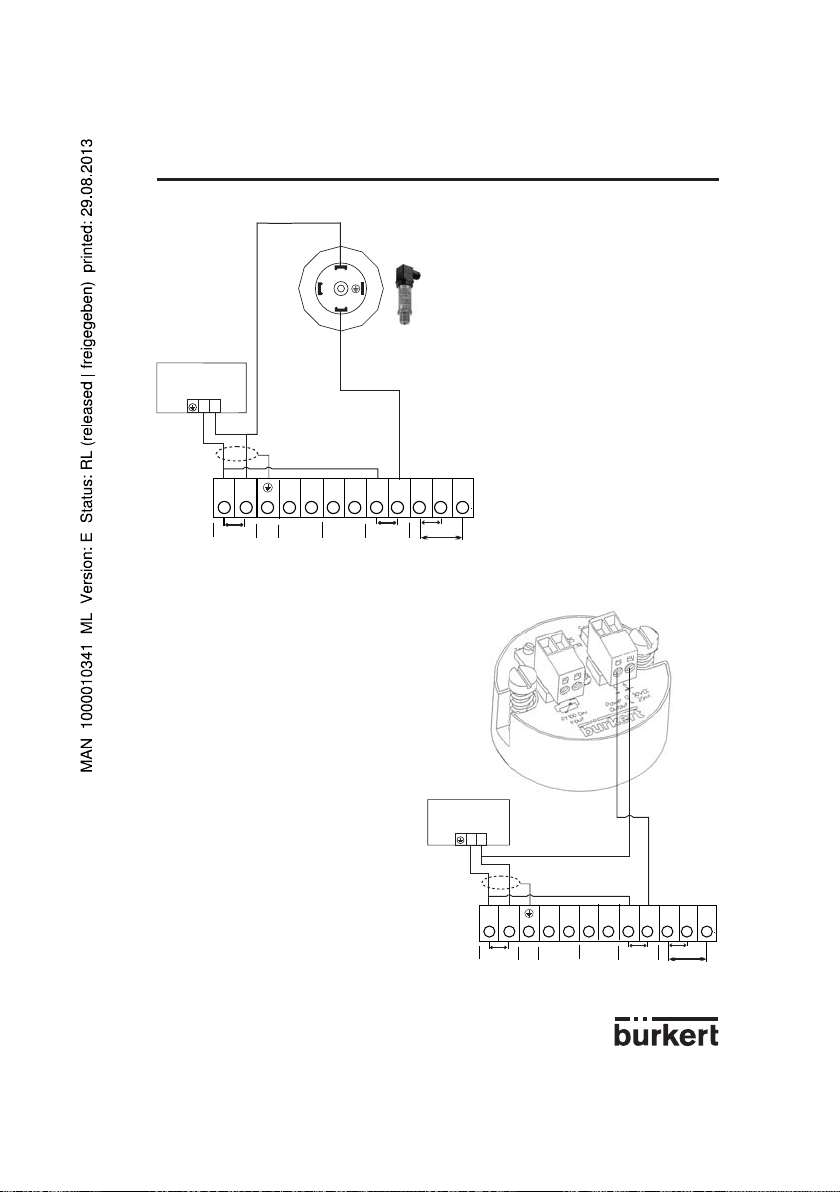
POSITIONER 1067ANSCHLUSS-BEISPIELE
-
+ 24 V
I/O4
I/O3
I/O2
I/O1
GND2
I2
I1
U1
GND1
24 VDC
PE
4-20 mA
0/4-20 mA
0-10 V
24 V=
-
+
8323
1067
3
2
1
4-20 mA
L+
-
+ 24 V
I/O4
I/O3
I/O2
I/O1
GND2
I2
I1
U1
GND1
24 VDC
PE
4-20 mA
0/4-20 mA
0-10 V
24 V=
-
+
ST25
1067
Anschluss zwischen dem Positioner
1067 and dem Druck-Sensor 8323.
Anschluss zwischen dem Positioner
1067 and dem Temperatur-Transmitter ST25.
D-51-
Page 52

POSITIONER 1067ANHANG
D-52-
Page 53

TABLE OF CONTENTS
1 INTRODUCTION ..........................................................................................................................................E-2
1.1 Unpacking and inspecting ........................................................................................................................... E-2
1.2 General notes on use and safety ...............................................................................................................E-2
1.3 Electromagnetic compatibility .....................................................................................................................E-2
2 DESCRIPTION .................................................................................................................... E-3
2.1 Characteristics and possible applications ............................................................................................... E-3
2.2 Construction ...................................................................................................................................................E-5
2.3 Principle of operation ....................................................................................................................................E-6
2.4 Safety position ................................................................................................................................................E-7
2.5 Technical data ................................................................................................................................................E-8
3 INSTALLATION ................................................................................................................... E-9
3.1 Construction and assembly.........................................................................................................................E-9
3.1.1 Fitting the positioner to a continuous valve with membrane drive (NAMUR) ......................E-9
3.1.2 Fitting the positioner to a continuous valve with piston drive .............................................. E-11
3.1.3 Fitting the positioner, remote version ........................................................................................ E-13
3.1.4 Fitting the positioner to a continuous valve with rotary drive ...............................................E-15
3.2 Fluid ports..................................................................................................................................................... E-16
3.3 Electrical connections ............................................................................................................................... E-17
4 OPERATION ..................................................................................................................... E-18
4.1 Controls and indicators ............................................................................................................................. E-18
4.2 Operating levels .......................................................................................................................................... E-18
4.3 Setting up ..................................................................................................................................................... E-19
4.4 Process control ........................................................................................................................................... E-21
4.4.1 Meaning of LEDs and keys in the process control level ....................................................... E-21
4.4.2 Displays ............................................................................................................................................E-21
4.5 Configuration ............................................................................................................................................... E-23
4.5.1 Additional functions ....................................................................................................................... E-23
4.5.2 Configuration menu ....................................................................................................................... E-25
4.5.3 Function of keys in the configuration level ............................................................................... E-27
4.5.4 Notes on the basic and additional functions ........................................................................... E-27
4.6 Manual operation without power supply ............................................................................................... E-36
4.7 Structure of the positioner ........................................................................................................................ E-37
5 MAINTENANCE ................................................................................................................ E-38
5.1 Fault messages ........................................................................................................................................... E-38
5.2 Spare parts ordering codes ..................................................................................................................... E-38
APPENDIX ........................................................................................................................ E-39
A1: Characteristics of PID controllers ...................................................................................................E-39
A2: Rules for adjusting PID controllers ................................................................................................. E-43
A3: Optional board for analog position indication ..............................................................................E-46
A4: Optional board for binary position indication/Booster ............................................................... E-47
A5: Examples of connections with the positioner 1067.................................................................... E-49
POSITIONER 1067
E-1-
Page 54

Dear Customer,
!
To be able to make the best use of the many advantages the product has to offer, it is absolutely
necessary to follow our advice and
READ THESE OPERATING INSTRUC-TIONS CAREFULLY BEFORE FITTING THE
UNIT AND PUTTING IT INTO SERVICE
POSITIONER 10671 INTRODUCTION
for electrical equipment shall be complied with
during the operation, servicing and repair of the
positioner.
Repairs may only be carried out by authorised
trained personnel.
1.1 Unpacking and inspecting
Please check the delivery for completeness and
transportation damage. The standard delivery
includes:
-1 Positioner 1067
-1 Instruction Manual
In the event of loss or damage please contact
your Bürkert Subsidiary.
1.2 General notes on use and
safety
This publication contains no warranty statement
For this we refer to our general purchase and
delivery conditions.
To ensure proper functioning and a long life
of the positioner, the user must observe these
Operating Instructions as well as complying
with the installation conditions and permissible
data as given in the data sheet. Installation and
maintenance personnel must have training and
qualifications suitable for the task.
Suitable measures are to be taken to prevent
unintentional actuation and the resulting effect
on the process. Safe electrical isolating and
shut-off devices for the media must be provided
for the installation task. If the positioner is part
of a complex automated system, a defined and
controlled restart of the automated system after
an interruption shall be guaranteed in accordance
with the instructions.
The accident and prevention safety regulations
This symbol is shown in the Operating
Instructions each time particular care
is required to ensure correct installation, functioning and operating safety
of the equipment.
1.3 Electromagnetic compatibility
This device conforms to the EMC-Directive of the
Council of European Communities
89/336/EEC.
In order to comply with this directive, the wiring
instructions must be followed.
Master code
Unauthorised operation can be prevented at the
various operating levels by a freely-selectable
user code. Independent of this, there is a fixed,
programmed master code which cannot be
changed, by means of which all operations can
be performed. This four-digit master code is
given on the bottom margin of this page. It
can be cut out and kept separately from these
Operating Instructions.
Master code:
6568
E-2-
Page 55

2 DESCRIPTION
POSITIONER 1067
2.1 Characteristics and possible applications (overview)
The 1067 positioner is an electropneumatic position controller for pneumatically actuated continuous
valves. The device includes the following main functional groups: a feedback/positional transducer, an
electropneumatic system and a microprocessor electronic system. The feedback/positional transducer
measures the actual position of the continuous valve. The microprocessor electronic system continuously compares the actual position (actual value) with a desired position value that was preset via the
standard signal input and supplies the result to the position controller. If an error exists, the electropneumatic system causes the actual position to be appropriately corrected.
The 1067 positioner can be fitted to various continuous valves (e.g. valves with piston, membrane or
rotary drives and with single or double action). Three variant forms of the basic device are offered that
differ in their fixing options and feedback/positional transducers
In variant 1, an internal feedback/positional transducer is used that takes the form of a rotary potentiometer.
In variant 2, an external linear potentiometer serves as feedback/positional transducer.
In variant 3, an external linear potentiometer serves as feedback/positional transducer and the positioner is mounted on a DIN rail and not on the valve directly.
The positioner also implements a PID controller by means of which, in addition to position control, process control (e.g. level, pressure, flow or temperature control) can be achieved in the form of sequence
control.
A liquid-crystal display and a keypad with three keys are provided for operating the positioner. An operating concept with the following graded operating levels has been implemented:
- Process operation
This level allows switching between automatic and manual operation, and enables manual actuation.
- Confi guration
Configuration level is used to specify certain basic functions when the positioner is taken into service
and, if necessary, to configure additional functions.
E-3-
Page 56

Fig. 1 Block diagram of the 1067 positioner
Position controller with
additional functions, e. g.
- close tight function
- plug travel limitation
- setting speed limitation
- split range
- correction characteristics
- deadband
- safety position
Additional integrated process controller
with the following features:
- adjustable parameters
- scalable inputs
- setpoint setting via input signal or
keys
Automatic adaptation of position
controller to the continuous valve in use
Hierarchical operating concept for
simple, staged-level operation
POSITIONER 10672 DESCRIPTION
Input for position or
process setpoint
0...10 V
0...20 mA
4...20 mA
Input for process actual
value
4...20 mA
Binary input (contact)
24 VDC
Characteristics, functions
Positioner
Inputs
1067
Power
Operation
E-4-
Analog output (option)
Output
Page 57

2 DESCRIPTION
POSITIONER 1067
2.2 Construction
The positioner consists of the following main assemblies:
- Body and bonnet (aluminium)
- internal feedback/positional transducer for measuring valve position
- Microprocessor/electronic unit for signal processing and control
- Solenoid valves for control of a continuous action valve
- Fluid plate with fluid ports
- Terminals and cable glands
- Display and keyboard
Fig. 2 Cross section of the positioner with internal feedback/positional transducer (variant 1)
Aluminium body and
bonnet with hinge
Electronic
Display and keypad
Manual operation
Connection
terminal
Internal feedback/positional
transducer for connection
according to NAMUR
Positional
transducer shaft
Solenoid valve
Fluid ports
Cable gland
Fluid plate
In variant 2, an external linear potentiometer serves as feedback/positional transducer (see fig. 3).
Fig. 3 External feedback/positional transducer (for variants 2 ad 3)
E-5-
Page 58

2 DESCRIPTION
POSITIONER 1067
2.3 Principle of operation
Fig. 4 shows a operational diagram of the positioner with its relationship to a piston drive control valve.
An external feedback/positional transducer (variants 2 and 3) is used in this case to measure the actual
position.
Fig. 4 Operational diagram
Feedback/positional
transducer
Piston
valve
The position (actual position) of the valve drive is determined by the feedback/positional transducer.
The signal corresponding to the actual position is continuously compared in the positioner with the
desired position and the error (control deviation) is formed. Pulses of variable duration corresponding
to the error are delivered to the magnetic valves of the electropneumatic system, by means of which the
supplied air and outgoing air for positioning the actuating drive of a continuous valve are controlled. The
desired position can be preset either via a standard signal input from outside (e.g. manually or via an
external controller) or via the internal process controller. In the latter case, the desired process value is
applied to the standard signal input or entered via keypad and a comparison is made with the process
quantity (e.g. flow, pressure, level or temperature) that is to be controlled (Fig. 4).
If the desired position is preset externally via the standard signal input provided for that purpose (i.e. if
the internal process controller is not used), the device works as a position controller only (Fig. 5). The
position controller is implemented as a PD controller within the microprocessor. A pulse-width modulation (PWM) member is connected to the controller output and, via its B1 and E1 outputs, the magnetic
valves for supplying air to and venting the actuating drive are controlled. When a positive error exists,
pulses (PWM signals) are output from output B1 to switch the supplied air. When a negative error
exists, pulses are output from output E1 to switch the outgoing air.
The positioner can be supplied for both single-acting and double-acting actuating drives. The PWM
member has two further outputs, B2 and E2, via which the two additional magnetic valves for supplying
air to and evacuating air from double-acting actuating drives are controlled.
If the internal process controller is used, it constitutes a component in a higher-level control loop (main
control loop). The position controller mentioned above now operates in a lower-level auxiliary control
loop. The overall effect is sequence control (Fig. 6). The internal process controller (main controller) is
implemented as a PID controller (Z1 and Z2 representing disturbance variables).
External setpoint
Actual-position
Set
position
Position
controller
Solenoid valves
Process setpoint
Process
controller
Air inlet
Air exhaust
Sensor
Process value (Pressure, flow, level...)
E-6-
Page 59

2 DESCRIPTION
Fig. 5 Position control
POSITIONER 1067
Setposition
Position controller
PWM element
Valve actuator
Fig. 6 Process control
Set
position
Process
controller
Position controller
Main control loop
PWM-element
Auxiliary control loop
Valve actuator
Process
2.4 Safety position
In the event of power failure, the functioning of the actuator ensures that a pre-determined end position
is adopted (opened or closed by spring pressure).
E-7-
Page 60

POSITIONER 10672 DESCRIPTION
2.5 Technical data
Electrical data
Power supply: 24 VDC ±10%, residual ripple 10%, No industrial DC
Power consumption: < 10 W
Input for desired value
Input for setpoint for position or process control:
- Unit signal 4 ... 20 mA
- Unit signal 0 ... 20 mA
- Unit signal 0 ... 10 V
Input for process signal (in case of process control):
- Unit signal 4 ... 20 mA
Binary input: Can be configured as a normally open or normally
closed contact.
Terminations: 1.5 mm2 bolted terminals
Two cable glands
Pneumatic data
Control medium: filtered compressed dry air, oiled or non-oiled
Dust content class 4,
max. particle size 15 µm,
max. particle density 8 mg/m
Dew point class 4 (+3 °C)
Oil content class 5, max. 25 mg/m
Pressure range: 0 ... 6 bar
Air rates
Inlet valve: 23 Nl / min
Exhaust valve: 25 Nl / min
Air consumption by unit
in stable state: 0 Nl / min
Unions: G 1/8" internal thread
(1)
When pressure reduction from 6 to 5 bar
Mechanical data
Regulation range of internal path-measuring system:
lift turn: 10...80 mm
rotary movement: 0...180°
Regulation range of external path-measuring system:
lift turn: 0...50 mm
Process controller data
Proportional correction value KP: 0...99,99
Reset time TN: 0.5...999.9
Rate time TV: 0.0...999.9
Operating point: 0...100%
Installation and operating data
External dimensions of positioner : 125 mm x 80 mm x 80 mm (W x H x D)
Material of body: Aluminium, lacquered
Material of the fluid plate: Aluminium, anodised
Weight of positioner: Approx. 1 kg
Degree of protection: IP 65
Operating temperature: 0 ... 60 °C
(1)
(1)
E-8-
3
3
Page 61

3 INSTALLATION
POSITIONER 1067
3.1 Construction and assembly
The 1067 positioner can be fitted to various continuous valves. Depending on the valve type either
variant 1, with an internal feedback/positional transducer (a rotary potentiometer) or variant 2 or 3, with
an external feedback/positional transducer (a linear potentiometer) is used (see section 2.3).
Main dimensions: Positioner External feedback/positional transducer
Width: 125 mm Diameter: approx. 65 mm
Height: 80 mm Height: approx. 95 (115) mm
Depth: 80 mm
3.1.1 Fitting the positioner to a continuous valve with membrane drive (according to NAMUR)
Arrangement
In the case of a continuous valve with membrane drive, device variant 1, with an internal feedback/
positional transducer (a rotary potentiometer) should be used. The positioner is screwed on to what is
termed the «lantern» of the membrane drive (Fig. 7). Transmission of the valve position to the internal
feedback/positional transducer is achieved by means of a lever conforming to NAMUR (Fig. 8).
Fig. 7 Fitting to a 265 continuous valve with
membrane drive
Assembly
A mounting elbow (Fig. 10) is provided for assembling variant 1 of the positioner to a continuous valve
with membrane drive (e.g. 265). The following steps should be carried out:
Screw mounting elbow "1" to the positioner using 4 x M6 "10" screws.
Fasten pin "2" using washer "7" and nut "8" to that position of the lever "4" which corresponds with the
desired lift (the lever is marked in mm of lift).
To avoid a TURN POT error (dead zone of the path-sensor), position the shaft of the path-sensor of
the positioner so that during the whole lift of the actuator the flattened part never passes in front of the
yellow mark (see following picture).
Fig. 8 Rear view of positioner (variant 1) with
lever
Flattened part on the shaft
of the path-sensor
Put lever "4" with pin on to the path-sensor shaft. Then screw lever tight with screw "9". Fasten carrier
"3" with cheese-head bolts "6" to the lifting rod of the membrane valve.
E-9-
yellow mark
Page 62

3 INSTALLATION
Fig. 9 Position of lever during assembly
Parallel
Set positioner, with the mounting elbow "1" screwed on to it, on the membrane drive so that the pin
"2" slots into the carrier "3", the point of the lever runs parallel with the upper edge of the positioner
(Fig. 9) and the rear side of the positioner runs parallel with the carrier "3". Fasten the positioner to the
membrane drive in this position as appropriate to the following variants:
- In the case of membrane drives with pillar lanterns, fasten mounting elbow "1" with two U-bolts "5",
nuts "13" and washers "12" to the appropriate pillar lantern (Fig. 10a).
- In the case of membrane drives with cast lanterns, fasten mounting elbow "1" with one screw "13"
(Fig. 10b) or four screws "13" (Fig. 10c) to the appropriate cast lantern (Fig. 10a).
Fig. 10 Assembly of positioner to a continuous valve with membrane drive
POSITIONER 1067
E-10-
Page 63

3 INSTALLATION
3.1.2 Fitting the positioner variant 2 to a continuous valve with piston drive
Arrangement
A continuous valve with piston drive can be used with variant 2 of the positioner with the external pathmeasuring system (Fig. 14). The positioner is placed on the valve and screwed to it (Figs. 11 and 12).
The valve position is transmitted directly via the spring-mounted rod of the path-measuring system (the
linear potentiometer).
Fig. 11 Fitting to a 2731 continuous valve
with piston drive
Assembly
Assembly of variant 2 of the positioner to a continuous valve with piston drive.
A set of add-on parts (NAMUR adapter, Fig. 13) is provided for assembling variant 2 of the positioner
to a piston valve (e.g. 2731). It consists of a mounting plate "1", two hollow bolts "2", three O-rings "3"
and two cheese-head bolts M5 "4".
To assemble the positioner on a continuous valve with piston drive, the following steps should be
carried out (Fig. 13):
Place an O-ring "3" in the recess of the mounting plate "1" (drive side). In the case of a large version,
place a second O-ring on the other side of the mounting plate.
Put two cheese-head bolts M5 "4 "from the drive side through the 5-mm drillings in the mounting plate.
Screw the preassembled mounting plate "1" to the two connection pieces of the valve drive with two
hollow bolts "2" so that the lower connection piece is sealed by the O-ring.
Place an O-ring "3" in the groove on the reverse side of the positioner.
Add the positioner to the mounting plate and screw it on with the two cheese-head bolts "4".
Fig. 12 Rear view of positioner (variant 2)
POSITIONER 1067
E-11-
Page 64

3 INSTALLATION
To assemble the external feedback/positional transducer, refer to the mounting instructions on pages
E13 and E14:
- carry out steps a) to g) (page E13 and fig. 17)
- insert the positioner cable "7" through the cable gland "5" of the feedback/positional transducer
(see fig. 13 and 14)
- carry out steps l) to m) (page E14 and fig. 17).
Fig. 13 Diagram for the assembly of positioner variant 2 and external feedback/positional
transducer on a continuous valve with piston drive (conforming to NAMUR)
POSITIONER 1067
Fig. 14 External feedback/positional transducer
E-12-
Set of add-on parts for
Bürkert piston drive (ø125)
5
6
Page 65

3 INSTALLATION
3.1.3 Fitting the positioner variant 3 for a continuous valve with piston drive
Arrangement
A continuous valve with piston drive can be used with variant 2 of the positioner with the external
feedback/positional transducer (Fig. 14) which is set on the valve and screwed to it (Fig. 15). The valve
position is transmitted directly via the spring-mounted rod of the path-measuring system (the linear
potentiometer).
Fig. 15 Continuous valve with piston drive
and remote positioner (variant 3)
Assembly
Variant 3 of the positioner is mounted on a DIN rail.
To mount the external feedback/positional transducer, do the following (refer to Fig. 17):
a) Make sure that an O-ring has been inserted into the valve actuator (top). Insert ring "6" if necessary.
b) Unscrew fastening screw "3".
c) Place the plastic ring "4" on the top of the actuator "5" (sizes 100 and 125 only) then screw the
external feedback/positional transducer (fig. 14) on it.
d) Tighten fastening screw "3".
e) Unscrew housing "11" of the external feedback/positional transducer.
f) The cable of the path-measuring system must be placed behind the latter so that it does not hinder
the displacement of the spindel of the feedback/positional transducer.
Path-measuring system
Cable
Fig. 16 Rear view of positioner for mounting
on a DIN rail
POSITIONER 1067
Slot for the electronic board
E-13-
Page 66

+
-
A
1
2
4
5
6
7
8
12
3
9
10
11
3 INSTALLATION
g) Place the cursor of the path-measuring system into the groove "9" of the spindle "8" of the feedback/positional transducer and set this spindle onto the spindel of the actuator. Fasten screw "10".
h) Insert electronic board "2" into the slot of the positioner housing.
i) Inside the housing, connect plug "1" of the path-measuring system to the connector of the electronic board, with respect to the wire colours (blue mark)
j) Cut cable "12" at the desired length and pull it through the cable gland "7" of the external feedback/
positional transducer.
k) Connect cable "12" to the connector of the electronic board:
- : brown
A : white
+ : green
l) Tighten the cable gland "7".
m) Screw the housing "11" of the external feedback/positional transducer.
POSITIONER 1067
Fig. 17 Diagram for the assembly of positioner variant 3 and external feedback/positional
transducer
E-14-
Page 67

3 INSTALLATION
3.1.4 Fitting the positioner to a continuous valve with rotary drive
Note: When the 1067 is mounted on a double-acting actuator for regulation purposes, select an actuator size bigger than the one indicated in the couple dimensioning table.
Connect the pneumatic connection A1 to the actuator chamber which axis rotates clockwise when air
is supplied.
Arrangement
In the case of a continuous valve with rotary or part-turn valve actuating drive, variant 1 with an internal
feedback/positional transducer should be used. Its shaft is coupled to the valve rotary drive (e.g. flap
valve). The position of the rotary drive is thus transmitted directly to the shaft of the feedback/positional
transducer.
Fig. 18 Fitting to a continuous valve with
rotary drive
Assembly
A coupling (adapter) "1" is provided for assembling variant 1 of the positioner on to a continuous valve
with a rotary or part-turn valve actuating drive (e.g. 3210, Fig. 20). In addition, an assembly clip "3" (Fig.
21) is required and can be obtained from the manufacturer of the part-turn valve actuating drive. (It is
normally used for the assembly of a limit-switch box).
To assemble, the following steps should be carried out (Fig. 21):
Secure the assembly clip "3" to the valve drive.
Place the coupling "1" on the shaft of the positioner’s feedback/positional transducer. The setscrew "2"
on the coupling should first have been slightly withdrawn.
Place the positioner on the assembly clip. Ensure that the flat piece of the coupling fits into the slot in
the end of the drive shaft.
Secure the positioner on the assembly clip with 4 x M6 screws.
Fix the coupling to the shaft of the feedback/positional transducer by screwing in the setscrew "2".
If after the AUTOTUNE function is started the message TURN POT is displayed on the LCD, the setscrew must be loosened and the shaft of the path-measuring system rotated 180° relative to the drive.
The setscrew should then be screwed tight and the AUTOTUNE function repeated.
Fig. 19 Reverse side of positioner (variant 1)
with securing holes
POSITIONER 1067
E-15-
Page 68

POSITIONER 10673 INSTALLATION
Fig. 20 Coupling for continuous valve with
rotary drive
Fig. 21 Assembly of positioner on to a continuous valve with rotary drive
Continuous valve with rotary drive
3.2 Fluid ports
Connect P port with compressed air supply (6 bar max.) before connecting the electrical power supply.
Fig. 22 Connection examples on continuous valve with membrane drive
Single acting Double acting Single acting, parallel
(for higher flow)
E-16-
Page 69

3 INSTALLATION
POSITIONER 1067
3.3 Electrical connections
Fig. 23 Assignment of terminals
Signal input:
- either for valve
position control
- or for process
regulation control
Input for process
regulation
Binary input
Contact
Output
(Option)
Power Supply
Input U1 (unit signal 0 ... 10 V): Input resistance 200 kΩ
Input I1 (unit signal 0/4 ... 20mA): Input resistance < 175 Ω
Input I2 (unit signal 4 ... 20mA): Input resistance < 175 Ω
Caution: To ensure the electromagnetic compatibility (EMC) of the device connect
the M4 internal thread of the positioner holder to the earth using a cable as short
as possible.
E-17-
M4 thread
Page 70

4.1 Controls and indicators
POSITIONER 10674 OPERATION
AUTOTUNE
LED
„Arrow up“ key
„Arrow down“ key
MANUAL/AUTOMATIC key
4.2 Operating levels
2 operating levels are provided for operation of the positioner:
1° Process operation level
This level, which is automatically set each time the unit is switched on, allows to change over between
the MANUAL and AUTOMATIC operating modes. In the MANUAL mode the valve can be opened or
closed by operating the „arrow keys“.
2° Confi guration level
The purpose of the configuration level is to enable the basic functions to be specified on initial commissioning and additional functions to be configured as required.
Each time the power is switched on, the positioner is in the process operation level in the AUTOMATIC mode. A changeover to the MANUAL mode can be accomplished using the MANUAL/AUTOMATIC
key (cf § 4.4). From the process operation level it is possible to change over to the configuration
level by pressing the MANUAL/AUTOMATIC key and holding for 5 seconds.
E-18-
Page 71

4 OPERATION
POSITIONER 1067
4.3 Setting up
The following basic settings are to be carried out on the initial setting up (commissioning) of the positioner in conjunction with the valve (specification of basic functions):
- Specification of the positional feedback of the continuous valve to the positional transducer (direct or
lever),
- Specification of the unit signal input chosen for entering the set position (0 ... 20 mA, 4 ... 20 mA or 0
... 10 V),
- Initiating the automatic adaptation of the actuator to the valve being used.
When the power is switched on, the positioner is in the process control level. It is necessary to switch
to the configuration level for specification of the basic functions. To do this, press the MANUAL/AUTOMATIC key and hold for 5 seconds. The first menu point X-SENS of the main menu is then displayed.
Fig. 24 Main menu for fi rst setting up
Function
AUTOMATIC
or
MANUAL
E-19-
after 30 to 120 sec.
BLINKING
Page 72

POSITIONER 10674 OPERATION
To perform a setting within the X-SENS and INPUT menu items, briefly press the MANUAL/AUTOMATIC key again. One of the menu sub-items then appears in the display. It is possible to switch back
and forwards between these sub-items, each of which describes a possible setting, by again pressing
the arrow keys. The actual setting is carried out by pressing the MANUAL/ AUTOMATIC key on the
selected menu sub-item.
Fig. 25 Signifi cation of the menu options in the main menu
Basic function Associated settings
X-SENS Type of information transfer between the actuator and travel measuring
system (factory-set to DIRECT)
- DIRECT - Linear relationship
- LEVER - Sinusoidal relationship (use of a lever)
INPUT Specification of selected unit signals
- 4 ... 20 MA - Unit signal current 4 ... 20 mA
- 0 ... 20 MA - Unit signal current 0 ... 20 mA
- 0 ... 10 V - Unit signal voltage 0 ... 10 V
ADDFUNCT Configuration of additional functions
AUTOTUNE Actuation of automatic adaptation of the actuator to the valve
END End of menu
Under the menu option X-SENS, indicate whether the mechanical transmission of path information from
the positioner to the feedback/positional transducer is based on a linear or sinusoidal relationship. A
sinusoidal relationship results if the lever mechanism is used for the transmission of path information (cf.
section 3.1.1). In this event, when LEVER is confirmed an internal linearization takes place by means of
an approximated sinusoidal function.
The ADDFUNCT menu item can be skipped on the initial setting up. It is used only to configure additional functions.
The AUTOTUNE menu item is used to start the programme for automatic parametering of the positioner. This automatically triggers the following functions:
- Matching the sensor signal to the (physical) stroke of the control valve used.
- Determining parameters of PWM signals for control of the internal solenoid valves.
- Optimum adjustment of the control parameters of the position controller (target function: fastest possible movement to the set position without hunting).
The programme for automatic parametering is started by setting the AUTOTUNE menu item in the main
menu and then pressing the MANUAL/AUTOMATIC key and holding for 5 seconds. TUNE is displayed
with a countdown from 5 to 0. The word AUTOTUNE then flashes for approximately 30 to 120 seconds
(depending on the actuator volume). After the flashing ends, the message TUNE END is displayed.
Note: In case of complete delivery of a valve fitted with a positioner, the AUTOTUNE function has
already been run through in factory. In order to obtain the best accuracy, it is recommended to run the
AUTOTUNE function once more before putting the valve in operation.
If it is not possible to fully complete the AUTOTUNE routine, an error message is displayed (refer to the
list of error messages in part 5).
E-20-
Page 73

4 OPERATION
To leave the main menu for the settings during the setting up, first select the END menu item by
pressing the arrow keys. Then press the MANUAL/AUTOMATIC key to restore the unit to the operating
mode which was present before the changeover to the main menu (MANUAL or AUTOMATIC).
POSITIONER 1067
4.4 Process operation
4.4.1 Meaning of LEDs and keys in the process operation level
LED Green LED in the MANUAL/AUTOMATIC key is on: AUTOMATIC mode
Green LED in the MANUAL/AUTOMATIC key is off: MANUAL mode
Keys
- Operation of the MANUAL/AUTOMATIC key (key pressed for less than 5 seconds) changes over
between the MANUAL and AUTOMATIC modes.
- Pressing the MANUAL/AUTOMATIC key and holding for longer than 5 seconds gives entry to the
configuration menu.
- Pressing the arrow keys in the AUTOMATIC mode with additional function PCONTRL SETPOINT
INTERN and display set to SP (holding for longer than 3 seconds): changes the setpoint value (see
section).
- Operation of the arrow keys in the AUTOMATIC mode (key held for less than 3 seconds) changes
over the display.
- Pressing the „Arrow up“ key in the MANUAL mode moves the actuator to open.
- Pressing the „Arrow down“ key in the MANUAL mode moves the actuator to closed.
4.4.2 Displays
Displays in the AUTOMATIC mode
Process controller inactive
The following displays are possible for the position controller.
Actual position of valve actuator: XPOS___ (0...100%)
Set position of valve actuator: WPOS___ (0...100%)
It is possible to change over between these displays by operating the „arrow keys“.
Process controller active
When the process controller is active, the following values can be displayed:
Actual value of process variable (actual process value): PV____ (-99.9...999.9)
Desired value of process variable (desired process value): SP____ (-99.9...999.9)
Actual value of valve drive: XPOS____ (0...100%)
Desired value of valve drive: WPOS____ (0...100%)
The arrow keys can be used to switch between these four displays. The «down arrow» key allows
paging through displayed values in the above sequence.
If the additional function PCONTROL SETPOINT INTERN (set desired value via keyboard) was specified during configuration, pressing either of the two arrow keys for more than 3 seconds while SP
(Setpoint) is shown in the display activates the mode for changing the desired process value. If the key
is released after this time, the first digit of the desired process value flashes on and off. This digit can
be changed by pressing the key again. After confirmation with the HAND/AUTOMATIC key, the set
value is accepted. The same process can be applied to the other digits. When the fourth digit has been
confirmed, the mode switches back.
E-21-
Page 74

POSITIONER 10674 OPERATION
Displays in the MANUAL mode
Process controller inactive
The actual position of the actuator is displayed: XPOS___ (0...100%)
Process controller active
In the HAND operating condition no operations are being carried out, the actual value of the process
quantity is continuously displayed: PV____ (-99.9...999.9).
If the arrow keys are pressed (cf. section) for manual actuation of the valve, the actual position is displayed: XPOS____ (0...100%)
When the keys are not being pressed, the display again shows the actual process value PV.
The changeover between the MANUAL and AUTOMATIC modes is achieved by operating the MANUAL/AUTOMATIC key.
If the „Arrow up“ key is pressed whilst in the MANUAL mode, the continuous action valve is continuously moved in the open direction by the actuator. When the key is released this operation is interrupted
and the valve remains in the position it has taken up. Pressing the „Arrow down“ moves the valve
towards the closed position in a corresponding manner.
If a different arrow key is additionally pressed after pressing an arrow key, the valve moves in rapid
action in the direction specified by the key which was first operated.
Changeover to the configuration level can be achieved in both the MANUAL and AUTOMATIC modes
by pressing the MANUAL/AUTOMATIC key and holding for 5 seconds. A switch back to the process
control level sets the mode which was present before the changeover.
Fig. 26 Overview of the operation structure
Operation mode
AUTOMATIC
(>3s)
Processsetpoint setting
Display
paging
Confi guration
END
(>5s)
V
V
/
/
No operation
SP
V
Close actuator
normal speed
/
Close actuator
high speed
Press key
Release key
/
/
V
Operation mode
MANUAL
(>5s)
No operation
END
Confi guration
E-22-
V
Press keys together
V
Release one of both
/
Open actuator
normal speed
V
/
Open actuator
high speed
Page 75

4 OPERATION
POSITIONER 1067
4.5 Configuration
4.5.1 Additional functions
The operating concept of the positioner is based on a strict separation between basic and additional
functions. Only the basic functions are activated in the delivery state of the unit. These enable the
unit-specific basic settings to be carried out on the initial setting up (cf § 4.3). These are adequate for
normal operation. For more demanding tasks of position and process control, additional functions which
have been preset in the configuration level, can be selected and specified.
The additional functions are listed below. For further informations about these functions , see § 4.5.4.
Fig. 27 Additional functions
Additional Parameter Description
function
ACTUATE Function of actuator
- SINGLE
INTERN Single acting actuator with intern or without boost valves
BOOST Single acting actuator with extern boost valves
- DOUBLE - Double acting actuator
CHARACT Selection of the transmission characteristic curve between the
input signal and stroke (correction characteristic curve)
- LINEAR - Linear characteristic curve
- 1 : 25 - Equal percentage characteristic line with a rangeability of 1 : 25
- 1 : 50 - Equal percentage characteristic line with a rangeability of 1 : 50
- 25 : 1 - Inverse equal percentage characteristic with a
rangeability of 25 : 1
- 50 :1 -Inverse equal percentage characteristic with a
rangeability of 50 : 1
- FREE - User-defined, characteristic line freely programmable
DEADBND - DBD Dead band with regard to the closed tight function system deviation
CLTIGHT Close tight function
- CLT - Closed tight threshold
DIRECTN WPOS Relationship between input signal and measure
- RISE - Direct direction of action
- FALL - Inverse direction of action
XPOS Relationship between ventilation of the actuators chamber A1
and the setpoint
- RISE - Direct direction of action
- FALL - Inverse direction of action
SPLTRNG Signal range splitting, input signal in % for the complete stroke
range through which the valve passes
- MIN - Input of minimum value of input signal.
- MAX - Input of maximum value of input signal.
E-23-
Page 76

POSITIONER 10674 OPERATION
X-LIMIT Limitation of mechanical range
- XMIN - Input of initial value of stroke range in %.
- XMAX - Input of final value of stroke range in %
X-TIME Limitation of correcting time
- OPN FAST - No limitation of correcting time during opening
- OPN SLOW - Limitation of correcting time during opening
- CLS FAST - No limitation of correcting time during closing
- CLS SLOW - Limitation of correcting time during closing
PCONTRL Process controller configuration
- SETPOINT - Method of presetting desired value
INTERN Desired value preset internally via keys
EXTERN Desired value preset externally via signal input
- PARAM - Process controller parameters
KP Proportional correction value
TN Reset time
TV Rate time
X0 Operating point
DBD No sensibility range of the process controller
- SCALE - Scalling input and setpoint values
DP Position of decimal point
PV-L Lower scale value for process quantity
PV-H Upper scale value for process quantity
SP-L Lower scale value for setpoint (only for SETPOINT EXTERN)
SP-H Upper scale value for setpoint (only for SETPOINT EXTERN)
BIN-IN Operation of binary input.
- INACTIVE - Binary input inactive
- SAFEPOS - Safety position
SPOS Position in %
- NORM OPN - Binary input open, if not active (closed)
- NORM CLS - Binary input closed, if not active (open)
OUTPUT Output configuration (option)
- ANALOG - Analog or process position feedback
- BINARY - Programmable Binary output
XDO Control value deviation alarm
XD Limit value of admissible control value deviation
NORM OPN Binary output normally open
NORM CLS Binary output normally closed
BOOST - Signal output for external Booster valve
CODE 4 Positions user code
- MENU+M/A Protection code for all operating functions
- MENU+M/A Protection code for configuration menus
E-24-
Page 77
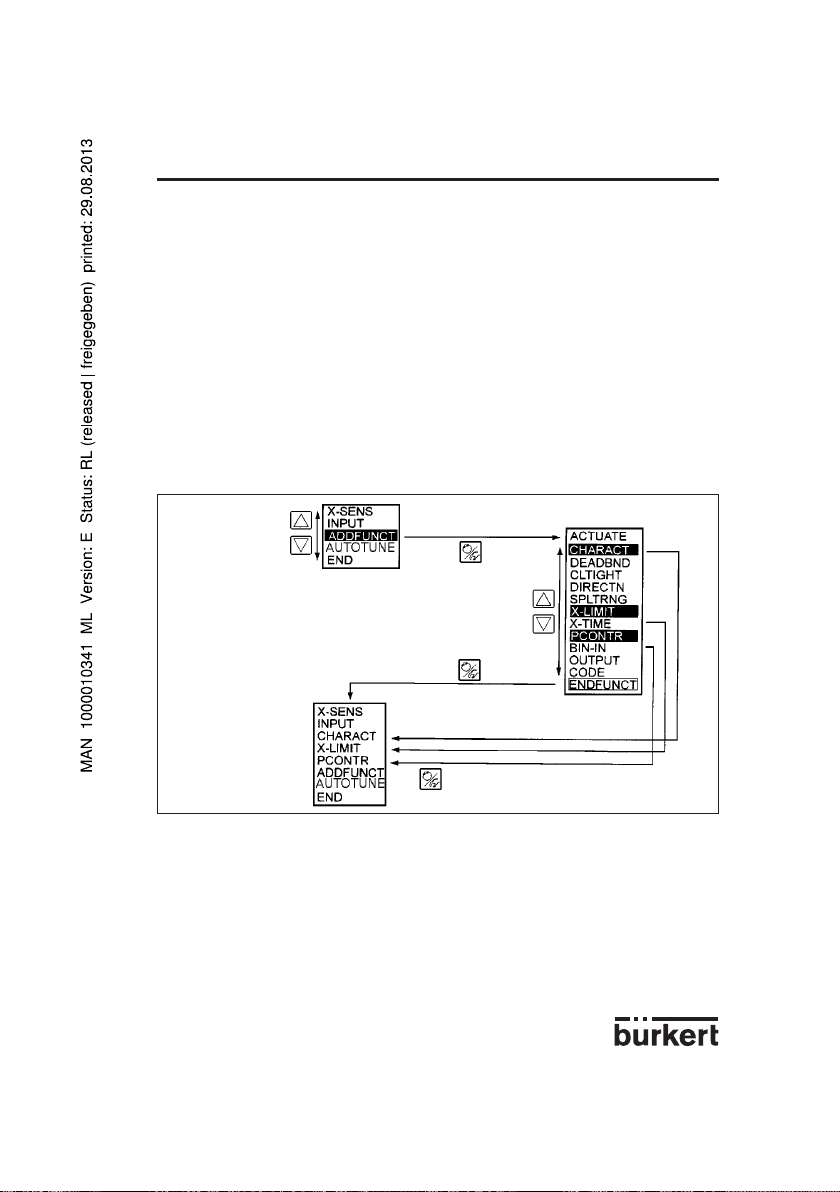
4 OPERATION
4.5.2 Confi guration menu
The configuration menu can be activated from the process control level by pressing the MANUAL/
AUTOMATIC key during 5 seconds. It consists of a main menu and additional menu. The main menu
contains mainly the basic functions which are to be specified on the initial setting up (cf § 4.3). The
additional menu covers all the additional functions which can be selected. It can be reached via the
ADDFUNCT item in the main menu. The equipment functions and parameters can only be specified
within the main menu. If necessary, however, the main menu can be extended by additional functions
from the additional menu, and these can in turn also be specified.
The principle of taking menu items from the additional menu into the main menu is described by figure
25. First select the ADDFUNCT item in the main menu and then press the MANUAL/ AUTOMATIC key
to enter the additional menu. When in the additional menu the „Arrow up“ or „Arrow down“ keys can
be pressed to set the required additional function. If this additional function is confirmed by pressing
the MANUAL/ AUTOMATIC key, it is then automatically marked with a star (*). All the functions marked
in this way are brought into the main menu after the ENDFUNCT is confirmed. The additional functions
can now be parametered in the main menu expanded in this way, and automatically activated.
Fig. 28 Principle of integration of additional function in the main menu
POSITIONER 1067
Selection of item
ADDFUNCT
Main menu
Confirmation of
selected item
Return to expanded
main menu
Additional menu
Expanded
main menu
To remove additional functions which have brought into the main menu, again select the ADDFUNCT
function and then press the MANUAL/AUTOMATIC key in the additional menu. If only one additional
function marked with a star (*) is now selected and confirmed by pressing the MANUAL/AUTOMATIC
key, it will then be removed from the main menu, and desactivated..
Fig. 26 shows the complete configuration menu with all the basic and additional functions. Continued
selection in the vertical direction is achieved by pressing the appropriate arrow keys. Press the MANUAL/AUTOMATIC key to move in the horizontal direction.
Setting numerical values in the appropriate menu items is achieved by pressing the „Arrow up“ key
once or several times (increment numerical value) or the „Arrow down“ (decrement numerical value). In
the case of 4-digit numbers, only the flashing position can be set using the „Arrow keys“. Pressing the
MANUAL/AUTOMATIC key changes to the next position.
Confirmation of selected
additional functions for
importation in main menu
E-25-
Page 78

Fig. 29 Complete confi guration menu
X-SENS DIRECT
LEVER
INPUT
4...20MA
0...20MA
0...10V
ACTUATE
DOUBLE
CHARACT LINEAR
1/25
1/50
25/1
50/1
FREE
0 5 100
DEADBND DBD
CLTIGHT CLT
DIRECTN
WPOS
XPOS
END
RISE
FALL
RISE
FALL
SPLTRNG MIN
MAX
X-LIMIT X-MIN
X-MAX
PCONTRL SETPOINT
PARAM
SCALE
INTERN
EXTERN
KP
TN TV X0
X-TIME OPN FAST
OPN SLOW
CLS FAST
CLS SLOW
SINGLE INTERN
BOOST
END
DBD
PV-H SP-L SP-H
PV-L
DP
BIN-IN INACTIVE
SAFEPOS
SPOS NORM OPN
NORM CLS
ADDFUNCT
AUTOTUNE
END
A
OUTPUT
BINARY
CODE
ANALOG
NORM CLS
XD
XDO
NORM OPN
BOOST
CODE MENU+M/A
MENU
WPOS
XPOS
PV SP
POSITIONER 10674 OPERATION
E-26-
Page 79

4 OPERATION
4.5.3 Function of keys in the confi guration level
Operation of the „Arrow up“ key
- Scroll upwards in menu (selection).
- Incrementing numerical values in a selected and confirmed menu item.
Operation of the „Arrow down“ key
- Scrolling downwards in the menu (selection).
- Decrementing numerical values in a selected and confirmed menu item.
Operation of the MANUAL/AUTOMATIC key within the main menu
- Confirmation of a selected menu item.
- Confirmation of a set value.
Operation of the MANUAL/AUTOMATIC key within the additional menu
- Confirmation of a selected menu item of the additional menu for inclusion in the main menu. The
selected menu item is marked with a star (*) in the additional menu. The menu item now appears in
the main menu where it can be selected and manipulated.
- Confirmation of a selected menu item of the additional menu, marked with a star, for deletion from the
main menu.
4.5.4 Notes on the basic and additional functions
X-SENS (factory setting: DIRECT): Specification of the type of information transfer between the conti-
nuous action valve (valve setting) and the travel measuring system.
Options:
DIRECT: There is a linear relationship between the valve position and the input signal
of the path-measuring system.
Examples:
Fitting the positioner to a piston valve (e.g. 2731) and using the external feedback/positional transducer (linear potentiometer) to measure the piston position. Here, the linear movement of the piston is
transformed into a linear movement of the potentiometer. A characteristic correction is therefore not
required.
Fitting the positioner to a flap valve with part-turn valve actuating drive (e.g. 3210) and using the
internal feedback/positional transducer (rotary potentiometer) to measure the flap position (see section
3.1.3 and Fig. 19). The rotary movement of the flap is converted into a proportional rotary movement of
the potentiometer. A characteristic correction is not required.
LEVER: There is a sinusoidal relationship between the valve position and the input
signal of the path-measuring system.
Example:
Fitting the positioner to a membrane valve (e.g. 265) and using the internal feedback/positional transducer (rotary potentiometer) to measure the valve position (see section 3.1.1 and
Fig. 7). Coupling is via a lever conforming to NAMUR. The linear movement of the membrane is transformed into a rotary movement of the potentiometer. A sinusoidal curve results. In this option, therefore,
the transmission characteristic is linearized internally.
INPUT (factory setting: 4 - 20 mA): Specification of the selected unit signal.
Options:
4 - 20 mA: Use of the 4 ... 20 mA unit signal input
0 - 20 mA: Use of the 0 ... 20 mA unit signal input
0 - 10 V: Use of the 0 ... 10 V unit signal input
POSITIONER 1067
E-27-
Page 80

4 OPERATION
ACTUATE (factory setting: SINGLE, INTERN): Method of operation of the valve actuator used.
Options:
SINGLE, INTERN: Use of a single acting actuator with intern or without boost valves,
SINGLE, BOOST: Use of a single acting actuator with boost valves,
DOUBLE: Use of a double acting actuator
CHARACT (factory setting: LINEAR):
Customer-specific characteristic.
This additional function enables a transmission
characteristic curve with regard to the desired
value of the setting (set position) and valve stroke
for correction of the flow or operating curve to be
chosen (Fig 30).
Fig. 30 Corrective characteristic curves
Plug travel
POSITIONER 1067
Set position
The flow characteristic kv = f
to the stroke s of the valve spindle. It is determined by the shape of the valve body. There are normally
two types of flow characteristic curves: linear and equal percentage. In the case of linear characteristic
curves equal changes in stroke ds are assigned to equal kv value changes dkv (dkv = n
an equal percentage characteristic curve a change in stroke ds corresponds to an equal percentage
change in the kv value (dkv/kv = n
The operating curve Q = f
a valve fitted in the system and the stroke s. This curve is also affected by the properties of the pipelines, pumps and consumers. It therefore has a form which deviates from the flow characteristic curve.
Specific requirements are usually laid down for the operating characteristic curve (e.g. linearity) in the
case of correcting tasks for closed loop control systems. Therefore it is sometimes necessary for this
reason to correct the pattern of the operating curve in a suitable manner. A transmission element which
implements various characteristic curves which can be used to correct the operating curve is provided
in the positioner for this purpose. One linear and various equal percentage characteristic curves with a
control ratio of 1:25, 1:50, 25:1 and 50:1 can be set (see fig. 30). It is also possible to freely programme a characteristic curve via restart points.
Options:
LINEAR Linear characteristic curve
1:25 Equal percentage characteristic curve with a control ratio of 1:25
1:50 Equal percentage characteristic curve with a control ratio of 1:50
25:1 Inverse equal percentage characteristic curve with a control ratio of 25:1
50:1 Inverse equal percentage characteristic curve with a control ratio of 50:1
FREE Freely-programmable characteristic curve based on temporary restart points
characterises the flow of a valve and is expressed by the kv value relative
(s)
ds). In the case
lin
ds).
gleichpr
represents the relationship between the rate of flow Q which flows through
(s)
E-28-
Page 81

4 OPERATION
Input of the freely-programmable characteristic curve
The characteristic curve is defined by means of 21 restart points distributed uniformly over the set positioning range of 0 ... 100%. These are spaced at 5%. A freely-selectable stroke (range 0 ... 100%) can
be assigned to each restart (Fig. 31). The difference between the values of the stroke of two adjacent
restart points shall not exceed 20%.
To input the characteristic curve points (function values), the FREE menu item is first set. After operation of the MANUAL/ AUTOMATIC key the first restart point is input with the display 0 (%). After this
the next function value is 0 (%). A function value from 0 to 100% can be set using the arrow keys. After
confirmation using the MANUAL/AUTOMATIC key the next restart point is shown on the display etc. If
finally the MANUAL/AUTOMATIC key is pressed to confirm the function value for the last restart point
(100%), the program switches back to the CHARACT menu item.
Fig. 31 demonstrates an example of the free programming of a correction curve.
POSITIONER 1067
E-29-
Page 82

Fig. 31 Example of a characteristic curve to be programmed
Plug travel (%)
POSITIONER 10674 OPERATION
Unit signal (%)
Set position (%)
Plug travel (%)
Input with "Arrow" keys
Restart point
E-30-
Page 83

4 OPERATION
DEADBND (factory setting : DBD = 0.5%): Deadband around the system deviation
The DEADBND additional function enables the response of the actuator to occur only after a specific
system deviation [DBD] (Fig. 32). This „protects“ the servo valve.
Fig. 32 Deadband DBD
POSITIONER 1067
Set position
Rangeability:
Maximum 5% relative to the stroke range.
The bottom limit is determined by AUTOTUNE.
CLTIGHT (factory setting: CLT = 0.5%): Closed tight function.
The closed tight function ensures that the valve is tightly closed outside the control range.
Fig. 33 Closed tight function
CLT: Closed tight threshold
Specification of a value (%) from which the actuator air is completely exhausted (at 0%) or supplied
with air (at 100%). The opening or resumption of the control operation takes place with a hysteresis of
1% (refer to Fig. 33).
Setting range:
0.0 ... 10.0% (applies both for complete exhausting as well as for complete air supply, see Fig. 33).
Control
difference
Actual position
Plug travel (%)
programmable from 90,0 to 100%
programmable from 0,0 to 10,0%
E-31-
To the controller
Set position (%)
Page 84

POSITIONER 10674 OPERATION
DIRECTN (FACTORY SETTING: WPOS = RISE, XPOS = RISE): Sense or direction of action.
By means of the WPOS additional function the sense of action between the input signal and the
setpoint (WPOS). can be set, and also by means of XPOS the assignment of the air supply state of the
actuator A1 to the indicated value (XPOS).
Input DIRECTN Setpoint
WPOS
I1 U1 (WPOS)
0/4 mA 0 V RISE 0 %
20 mA 10 V 100 %
0/4 mA 0 V FALL 100 %
20 mA 10 V 0 %
Air supply DIRECTN Measure
State A1 XPOS (XPOS)
Air exhaust RISE 0 %
Air on 100 %
Air exhaust FALL 100 %
Air on 0 %
SPLTRNG (factory setting: MIN = 0%, MAX = 100%): Split range
This additional function enables the set value range of a positioner to be restricted by stipulating a minimum and maximum value. This makes it possible to divide the used unit signal range (0 ... 10 V, 0 ... 20
mA or 4 ... 20 mA) over several positioners (without or with an overlap). In this way, several valves can
be partially used either simultaneously or in sequence as a final controlling element
(Fig. 35).
Fig. 35 Splitting a unit signal range into two set value ranges
Plug travel (%)
Fig. 34 Sense of action
0/4 mA Input signal 20 mA
0 V 10 V
air exhaust air on
Air supply state
RISE
FALL
RISE
FALL
Setpoint range
Setting range:
MIN: 0 ... 75 % of the unit signal range,
MAX: 25 ... 100 % of the unit signal range.
The minimum distance between MIN and MAX is 25%.
positioner 1
Setpoint range
positioner 2
E-32-
Setpoint (mA)
Page 85

4 OPERATION
X-LIMIT (factory setting: XMIN = 0%, XMAX = 100%): Stroke limitation.
This additional function enables the (physical) stroke to be limited to a given MIN and MAX percentage
value (Fig. 36). In the AUTOMATIC mode the stroke range of the limited stroke is then set to equal
100%. In the MANUAL mode, on the other hand, the physical stroke is displayed. (It should therefore
be noted that a limited stroke will be displayed differently in the AUTOMATIC and MANUAL modes).
Fig. 36 Stroke limitation
Limited plug
travel (%)
Setting range:
XMIN: 0 ... 50 % of the total stroke,
XMAX: 50 ... 100 % of the total stroke.
The minimum distance between XMIN and XMAX is 50%.
X-TIME (factory setting: OPN FAST, CLS FAST): Setting speed limitation
Options:
OPN FAST (open fast): Opening of the control valve happens with maximal control speed.
OPN SLOW (open slow): The maximum setting speed of the control valve is limited during
opening.
CLS FAST (close fast): Closing of the control valve happens with maximal control speed.
CLS SLOW (close slow): The maximum setting speed is limited when the control valve is
closing.
PCONTRL (process control): Process controller configuration
SETPOINT (factory setting: EXTERNAL): Preset desired value.
INTERN: Desired value can be input using the arrow keys (see § 4.4.2).
EXTERN: Desired value is preset via the standard signal input.
PARAM: Set parameters for process controller (PID controller)
KP: (Proportional correction value or amplification)
Range of settings: 0...99.99 (factory setting: 1.00)
TN: (reset time)
Range of settings: 0.5...999.9 (factory setting: 999.9)
Physical plug
travel (%)
Unlimited plug
travel (%)
POSITIONER 1067
Limited plug
travel (%)
Setpoint (mA)
E-33-
Page 86

POSITIONER 10674 OPERATION
TV: (rate time)
Range of settings: 0.0...999.9 (factory setting: 0)
X0: (Operating point of process controller)
Range of settings: 0...100% (factory setting: 0%)
DBD: No sensibility range of the process controller
Range of settings: 0,2...5% (factory setting: 0,5 %)
SCALE: Scales the inputs of the process controller.
Example of scaling: (fig. 37)
Actual process value via transmitter: 4...20 mA corresponds to 0...10 l/min
Desired process value from SPC: 4...20 mA corresponds to 0...8 l/min
DP: Decimal point position
Range of settings: 0 ... 3 (factory setting 0)
PV-L: Lower scale value for actual process value. It is assigned to the smallest current
or voltage value of the standard signal.
Range of settings: -99.9...990.0 (factory setting: 0.0)
PV-H: Upper scale value for actual process value. It is assigned to the greatest current
or voltage value of the standard signal.
Range of settings: -90.0...999.9 (factory setting: 100.0)
SP-L: Lower scale value for desired process value (setpoint). It is assigned to the
smallest current or voltage value of the standard signal. (Applies only with the setting
SETPOINT EXTERN).
Range of settings: -99.9...990.0 (factory setting: 0.0)
SP-H: Upper scale value for desired process value (setpoint). It is assigned to the
greatest current or voltage value of the standard signal. (Applies only with the setting
SETPOINT EXTERN).
Range of settings: -90.0...999.9 (factory setting: 100.0)
Fig. 34 Example of scaling
Scaling value (l/min)
Actual
process value
Process
setpoint
Standard signal (mA)
The input of large scale values increases display precision.
The amplification (KP) of the process controller relates to the set scale values.
With SETPOINT INTERN (desired values preset via the arrow keys) no scaling of the desired value
(SP-L, SP-H) is possible. It can be entered directly in correspondence with the scaled process variable
(PV-L, PV-H).
Possible scale-value inputs in the example of
scaling
Variante 1 Variante 2 Variante 3
PV-L 0 0 0
PV-H 1,0 10,0 100,0
SP-L 0 0 0
SP-H 0,8 8,0 80,0
E-34-
Page 87

4 OPERATION
BIN-IN (factory setting: INACTIVE): Binary input.
The action of the binary input (contact) can be specified by means of this additional function.
Options:
INACTIVE: Binary input is not active.
SAFEPOS (safety position): Input of a safety position SPOS selected if necessary.
Setting range: 0 ... 100% of the stroke range (factory setting: SPOS = 0).
NORM OPN (normalyl open): Binary input in de-energised position open (normallyopen contact or closer). Safety position is adopted when the contact closes.
NORM CLS (normally closed): Binary input in de-energised position closed (normallyclosed contact or opener). Safety position is adopted when the contact opens.
OUTPUT (option): (Additional function only activable with optional board.)
- ANALOG Analog or process position feedback (4...20 mA) (see Appendix 3)
- BINARY Programmable Binary output (see Appendix 4)
XDO Alarm deviation value exceeds XD
XD Deviation limit value ; Setting range: 0,1 ... 20% (Factory setting 1%)
NORM OPN Binary output normally open
NORM CLS Binary output normally closed
- ALARM Alarm signal, XMIN or XMAX threshold reached
XMIN Low alarm limit value ; Setting range: 0...100%
NORM OPN Binary output XMIN normally open
NORM CLS Binary output XMIN normally closed
XMAX High alarm limit value ; Setting range: 0 ... 100%
NORM OPN Binary output XMAX normally open
NORM CLS Binary output XMAX normally closed
BOOST Signal output for external Booster valve (see Appendix 4)
CODE (factory setting: 0000) User code. The positioner can be protected from unauthorised operation
by means of a 4-digit user code. 2 Levels of protection are available.
MENU+M/A: All functions protected by the user-code
MENU: Access to configuration menu restricted. MANU/AUTO switching and change
of process values are free (cf § 4.4.1).
Setting range: 0000 ... 9999
Regardless of the possibility of the existence of a preset code, there is a fixed programmed master
code which when entered enables all control operations to be performed.
ADDFUNCT (Additional functions): Additional functions.
This enables additional functions to be taken into the main menu and then removed (see § 4.5.2).
AUTOTUNE: Automatic parametering.
This function enables the program for automatic adaptation of the actuator to the valve in use to be
started. The following functions are automatically initiated (see section 4.3):
- The sensor signal is matched to the (physical) lift of the continuous valve,
- The parameters of the PWM signals are determined in order to control the internal magnetic valves,
- The parameters of the position controller are adjusted optimally.
This automatic setting of parameters is completed in approximately 30-120 seconds.
END: End of configuration menu.
(The software version is displayed on the right margin of the display). This menu item enables the configuration menu to be left by operation of the MANUAL/AUTOMATIC key (cf § 4.3).
POSITIONER 1067
E-35-
Page 88

POSITIONER 10674 OPERATION
4.6 Manual operation without power supply
The solenoid valves integrated in the positioner can be manually operated without a power supply by
using rotary knobs. These rotary knobs (red) are accessible when the bonnet of the unit is opened. They
are located immediately behind the electrical terminals. Two rotary knobs are provided on the type for
single-acting actuator (Fig. 38).
Fig. 38 Manual operation
Preconditions for manual operation using the rotary knobs.
- The power supply of the unit must not be connected under any circumstances.
- The pneumatic connections and the pressure supply must be present.
Settings
All rotary knobs are in position 0 (normal position):
Drive is vented.
In this case, in the design for double-acting actuating drives, the chamber connected to terminal A1 is
vented and the chamber connected to terminal A2 is supplied with air.
All rotary knobs are in position 1:
Drive is supplied with air.
In this case, in the design for double-acting actuating drives, the chamber connected to terminal A1 is
supplied with air and the chamber connected to terminal A2 is vented.
Caution!: All rotary knobs must be returned to the 0 position before connecting the power supply to
the positioner.
E-36-
Page 89

4 OPERATION
4.7 Structure of the positioner
Fig. 39 Flowchart of positioner
1067
POSITIONER 1067
E-37-
Automatic
Manual
Page 90

5 MAINTENANCE
POSITIONER 1067
5.1 Fault messages
Faults during switch on
Message Possible cause Remedy
INT.ERROR Internal fault Not possible, unit defective
Fault messages during AUTOTUNE function
Message Possible cause Remedy
TURN POT Range of the position transducer exceeded Remove the positioner from
(only with internal feedback transducer option) the actuator,and turn
the transducer from 180°. cf fig 2.
ERR 2 Actuator not adjustable Fit the positioner with
Opening time < 0.5 s bigger air chambers.
Reduce the air pressure
ERR 3 Actuator volume is too big use a positioner with valves
(opening time > 30 sec.) connected in parallel
ERR 4 Miscellaneous failure causes:
- manual operation of valve not - Check manual actuation
in basic setting parameters
- no air pressure connected - Check compressed air supply
- position transducer not connected - Check the electrical connection
of the transducer;If internal position
control system only.(cf fig. 2)
Check the mechanical coupling
of the position controler;if external
position control system (cf fig. 3)
5.2 Spare parts ordering codes
Designation Order code
Electronic board 553183
Power supply board, if connected to single-acting valve type 27xx 553184
Power supply board, if connected to single-acting valve type Namur 553185
Power supply board, if connected to double-acting valve type Namur 553186
Set of 2 rocker valves, DN0,6 553423
Set of 2 rocker valves, DN0,9 553424
Set of 2 rocker valves, DN1,2 553425
E-38-
Page 91

Y
Xd
Y0
Ymax
Ymin
Xd
Y
APPENDIX
t
t
X
Y
Xd
Kp.Xd
POSITIONER 1067
A1: Characteristics of PID controllers
A PID controller has a proportional, an integral and a differential component (P, I and D components).
P component :
Function : Y = Kp • Xd
Kp is the proportional action coefficient. It results from the ratio of the manipulating range ΔY to the
proportional range ΔXd.
Kp. Xd
Manipulat-
ing range
Proportional range
Characteristic Step response
Characteristics :
Theoretically, a pure P controller operates without delay, i. e. it is fast and therefore dynamically favorable. It has a lasting system deviation, i. e. it does not balance out the effects of disturbances completely
and is therefore relatively unfavorable from the static point of view.
I component :
Function : Y = ƒ Xd dt
Ti ist the integration or manipulating time. This is the time that elapses before the manipulated variable
has passed through the complete manipulating range.
1
Ti
E-39-
Page 92

APPENDIX
Xd
Xd
dY
dt
t
t
X
Y
Xd
Ymax
Ymin
Ti
t
t
X
Y
Xd
t
t
X
Y
Control range
Characteristic Step response
Characteristics :
A pure I controller eliminates the effects of occuring disturbances completely. Therefore, it has a
favorable static response. Owing to its finite manipulating speed, it operates more slowly than the P
controller and tends to oscillate. Therefore, it is relatively unfavorable from the dynamic point of view.
D component :
Function : Y= Kd
Kd ist the derivative action coefficient.
The higher Kd is, the stronger the D influence is.
d Xd
dt
POSITIONER 1067
range ΔY
Manipulating
Manipulating time
Step response Rise response
Characteristics :
A controller with a D component reacts to changes in the controlled variable and is accordingly capable
of dissipating occurring deviations faster.
E-40-
Page 93

APPENDIX
t
t
X
Y
}
}
}
Tv
t
t
X
Y
Xd
}
}
Tn
Supperposition of P-, I- and D components:
POSITIONER 1067
Y = Kp Xd + ƒ Xd dt + Kd
Where Kp•Ti = Tn and = Tv, results with regard to functioning of the PID controller:
Y = Kp (Xd + ƒ Xd dt + Tv )
Kp : Proportional action coefficient / gain
Tn : Reset time (the time needed to achieve the same manipulated variable change by the I com-
ponent as is produced as the result of the P component).
Tv : Derivative action time (the time to achieve a specific manipulated variable on the basis of
the D component earlier than when using a pure P controller).
D component
Reset time
Step response of the PID controller Rise response of the PID controller
1
Ti
Kd
Kp
1
Tn
I component
P component
d Xd
dt
d Xd
dt
I component
D component
P component
Derivative action time
E-41-
Page 94

Realised PID controller
D component with delay :
In the 1067 positioner, the D component is realised with a delay T.
Function : T + Y = Kd
dY
dt
dXd
dt
X
Xd
Y
Kd
T
POSITIONER 1067APPENDIX
t
T
Step response
Supperposition of P-, I- and DT components :
Function of the real PID controller :
T + Y = Kp (Xd + ƒ Xd dt + Tv )
X
Xd
Y
Tv
Kp
T
Kp Xd
dY
dt
Tn
1
Tn
t
t
d Xd
dt
Step response of the real PID controller
E-42-
t
Page 95

t
X
APPENDIX
POSITIONER 1067
A2: Rules for adjusting PID controllers
The litterature on control systems specifies a series of adjustment rules with which a favorable adjustment of controller parameters can be achieved experimentally. To avoid bad adjustments, the conditions under which the respective adjustment rules have been elaborated must always be observed. In
addition to the characteristics of the controlled system and of the controller itself, it is important to know
whether it is intented to balance out a disturbance change or a command variable change.
Adjustment rules according to Ziegler and Nichols (oscillation method)
When using this method, controller parameters are adjusted on the basis of the control loop's response
at the stability limit. In doing so, the controller parameters are adjusted so as to ensure that the control
loop begins to oscillate. A conclusion as to a favorable adjustment of the controller parameters is
reached from critical characteristic values occurring in this case. It goes without saying that, when using
this method, it must be possible to bring the control loop to oscillation.
Method:
- Set the controller as a P controller (i.e. Tn = 999, Tv = 0), initially selecting a low Kp value.
- Set the required setpoint.
- Increase Kp until the controlled variable oscillates continuously without attenuation (see following
figure).
Actual value
Tcrit
Figure : Progression of the control variable at the stability limit
The proportional action coefficient set at the stability limit is referred as Kcrit. The resulting oscillation
period is referred to as Tcrit.
E-43-
Page 96

APPENDIX
t
X
X
Tu
Tg
KS.
X
t
Y
Y
100%
On the basis of Kcrit and Tcrit, the controller parameters can then be calculated in accordance with the
following table:
Parameter settings according to Ziegler und Nichols :
Controller type Parameter settings
P controller Kp = 0,5 Kcrit
P controller Kp = 0,45 Kcrit Tn = 0,85 Tcrit
P controller Kp = 0,6 Kcrit Tn = 0,5 Tcrit Tv = 0,12 Tcrit
The Ziegler and Nichols adjustment rules were determined for P systems with a time delay of the first
order and a dead time. However, they apply only to controllers with a disturbance response, but not to
controllers with a command response.
Adjustment rules according to Chien, Hrones and Reswick (manipulated variable methode):
When using this method, the controller parameters are adjusted on the basis of the controlled system
transition response. Be a 100% change in the manipulated variable; The times Tu and Tg are derived
from the progression of the variable (following figure). Ks is the proportional action coefficient of the
system.
Actual value
POSITIONER 1067
Figure : Progression of the controlled variable after a manipulated variable change ΔY
Method :
- Set the controller to MANUAL mode.
- Output a manipulated variable change and record the controlled variable with a recorder.
- Switch off in good time if you encounter critical progressions (e. g. a risk of overheating) (Pay attention to the fact that, in thermally inert systems, the actual value of the controlled variable may increase
further switching off).
E-44-
Page 97

APPENDIX
The following table lists the settings for the controller parameters depending on Tu, Tg and Ks for command and disturbance response and for an aperiodic control operation as well as a control operation
with 20% overshoot. They apply to systems with a P response, with a dead time and with a delay of the
1st order.
Parameter settings according to Chien, Hrones and Reswick :
Parameter settings
Controller
type Aperiodic control operation Control operation with
(0% overshoot) 20% overshoot
Command Disturbance Command Disturbance
P controller KP = 0,3 Kp = 0,3 Kp = 0,7 Kp = 0,7
Tg
Tu • Ks
Tg
Tu • Ks
POSITIONER 1067
Tg
Tu • Ks
Tg
Tu • Ks
E-45-
Tg
Tu • Ks
Tg
Tu • Ks
PI controller Kp = 0,35 Kp = 0,6 Kp = 0,6 Kp 0,7
Tn = 1,2 Tg Tn = 4 • Tu Tn = Tg Tn = 2,3 • Tu
PID controller Kp = 0,6 Kp = 0,95 Kp = 0,95 Kp = 1,2
Tn = Tg Tn = 2,4 • Tu Tn = 1,35 • Tg Tn = 2 • Tu
Tv = 0,5 • Tu Tv = 0,42 • Tu Tv = 0,47 • Tu Tv = 0,42 • Tu
As shown in the figure of the previous page, the proportional action coefficient Ks of the control system
can be calculated by way of the increase in the inflectional tangent, i. e. by way of ΔX/ΔY: manipulated
variable change)
Ks =
ΔX
ΔY
Tg
Tu • Ks
Tg
Tu • Ks
Tg
Tu • Ks
Tg
Tu • Ks
Tg
Tu • Ks
Tg
Tu • Ks
Page 98

POSITIONER 1067APPENDIX
!
!
A3 : OPTION BOARD "4-20 mA ANALOG POSITION INDICATION"
(IDENT. 427193G): MOUNTING AND CONNECTION
The positioner must be equipped with the software version F, or higher. Check it in the main
menu, option END: it is displayed at the right-hand side of the screen.
Technical characteristics of the Option output of the positioner
- Output signal for the current value : 4-20 mA
- External working resistance / Input resistance of a connected device : 0-560 Ohms
- Output error rate : < 0,05 %
- Potential free output ; electrically separated from the position electronics.
Mounting
- Disconnect the positioner from the voltage supply
- Unscrew the 4 screws of the positioner cover and open the cover
- Remove the 2 red jumpers from the motherboard
- Insert the optional board onto the motherboard (see figure below)
Analog Option board
pins
Motherboard
Make sure the pins correctly slide into the motherboard.
- Pass the cables through one of the 2 PG9 cable glands, dismantle them over 6 mm and
connect them to the connection block according to the connection schematic (terminals I/O3
and I/O4)
- Close the cover and tighten the 4 screws, making sure neither the cables nor the wires are
wedged in.
Connection diagram
I1
U1
GND1
I2
GND2
I/O1
+24 V
I/O2
I/O3
+
-
I/O4
PE
-
Analog Option board
Motherboard
Confi guration
- Configurate the positioner as described in chapter 4.5.
- Activate the analog position indication by choosing the ANALOG option of the OUTPUT
function
0/4-20 mA
0-10 V
4-20 mA
IL = 4-20 mA
RL = 0-560 Ohm
24 V DC Supply Voltage
E-46-
Page 99

APPENDIX
!
!
POSITIONER 1067
A4 : OPTION BOARD "BINARY POSITION INDICATION/BOOSTER"
(IDENT. 192801): MOUNTING AND CONNECTION
- The positioner must be equipped with the software version F, or higher. Check it in the
main menu, option END: it is displayed at the right-hand side of the screen.
- For positioners manufactured before 1996 mounting is only possible if the
motherboard is fitted with black connection blocks (if not, please contact you nearest
Bürkert agent) .
Technical characteristics
Positioner Relay
- Operating voltage : 24 VDC - Contact type : closed
- Electric power consumption : max. 30 W - Commutation current : 0,5 A
- Electric connection : screw terminals, - Breaking capacity : 10 W
1,5 mm2 cross- - Contact resistance : 100 mOhm
section
Mounting
- Disconnect the positioner from the voltage supply
- Unscrew the 4 screws of the positioner cover and open the cover
- Remove the 2 red jumpers from the motherboard
- Insert the optional board onto the motherboard (see figure below)
Option board
pins
Make sure the pins correctly slide into the motherboard.
- Pass the cables through one of the 2 PG9 cable glands and dismantle them over 6 mm.
Motherboard
E-47-
Page 100

POSITIONER 1067APPENDIX
!
!
Connection
1) As potential free contacts
- connect the cables to the O5 and O6 or O7 and O8 terminals according to the connection
schematic
- place the jumper on the "REL" position (see figure below)
O5
O6+
O7
O8+
GND3
GND4
U
Rel
Rel
U
out
out
2) For connecting receivers to the outputs O6 and O8 (operating voltage of 24 V DC)
- connect the cables to the terminals O6 and O8 and to GND3 and GND4 according to the
connection schematic below.
For inductive receivers, use the recovery diode.
- place the jumper on the "U
U
out
Short-circuit hazard : before closing the device, make sure the screws of the connection
block are tightened.
" position (see figure below)
out
O5
O6+
O7
O8+
GND3
GND4
Rel
Rel
U
out
- Close the cover and tighten the 4 screws, making sure the cables are not wedged in.
Confi guration
- Configurate the positioner as described in chapter 4.5.
- Activate the binary position indication or the Booster function by choosing either the BINARY
or the BOOST option in the OUTPUT function.
E-48-
 Loading...