

Page 1
Type 1062
Electrical on/off position feedback
Elektrischer Auf/Zu-Stellungsrückmelder
Indicateur électrique de position tout ou rien
Operating Instructions
Bedienungsanleitung
Manuel d‘utilisation
Page 2
We reserve the right to make technical changes without notice.
Technische Änderungen vorbehalten.
Sous réserve de modifications techniques.
© Bürkert SAS, 2008-2013
Operating Instructions 1311/5_EU-ML 00562584 / Original FR
Page 3
Type 1062
Table of Contents
1. ABOUT THIS MANUAL ................................................................................ 5
1.1. Symbols used ...................................................................................... 5
1.2. Definition of the word "device" ................................................... 5
2. INTENDED USE ...............................................................................................6
2.1. Restraints ............................................................................................... 6
2.2. Ex certification .....................................................................................6
3. BASIC SAFETY INFORMATION .............................................................. 7
4. GENERAL INFORMATION ..........................................................................8
4.1. Manufacturer's address and international contacts ........ 8
4.2. Warranty conditions .......................................................................... 8
4.3. Information on the Internet ...........................................................8
5. DESCRIPTION .................................................................................................. 9
5.1. Area of application ............................................................................ 9
5.2. General description .......................................................................... 9
5.2.1. Construction ...........................................................................9
5.2.2. Principle of operation ...........................................................9
5.3. Description of the name plate on the standard 1062 ....9
5.4. Description of the name plates on the 1062 ATEX ...... 10
5.5. Versions available ........................................................................... 11
6. TECHNICAL DATA ....................................................................................... 11
6.1. Conditions of use ............................................................................ 11
6.2. Conformity of the 1062 ATEX to standards
and directives .................................................................................... 11
6.3. Conformity of the 1062 approved by CSA ......................... 12
6.4. General technical data ................................................................. 12
6.4.1. Mechanical data .................................................................12
6.4.2. General data ........................................................................13
6.4.3. General data specific to the devices approved by
CSA ....................................................................................... 14
6.4.4. Electrical data......................................................................14
7. ASSEMBLY ...................................................................................................... 16
7.1. Safety instructions.......................................................................... 16
7.2. Replacing the top part of an actuator size 40mm ......... 17
7.3. Fitting the position feedback to a pneumatic actuator 1 7
7.4. Fitting the position feedback with stroke
limiter to a pneumatic actuator size 50 to 80mm ......... 19
7.5. Fitting the position feedback with stroke
limiter to a pneumatic actuator size 100 or 125mm .... 23
english
3
Page 4
8. INSTALLATION AND WIRING ................................................................26
8.1. Safety instructions.......................................................................... 26
8.2. Electrical wiring ................................................................................ 27
8.2.1. Wiring a mechanical contact version ............................28
8.2.2. Wiring a version with inductive 2-wire switch ............. 30
8.2.3. Wiring a version with inductive 3-wire switch ............. 31
8.2.4. Wiring a version with two inductive 3-wire switches 31
8.2.5. Wiring a version with double inductive 2-wire
NAMUR switch ...................................................................32
8.2.6. Wiring a version with double inductive 4-wire switch 3 4
9. COMMISSIONING ....................................................................................... 34
9.1. Safety instructions.......................................................................... 34
9.2. Setting the cams ............................................................................. 34
10. MAINTENANCE AND TROUBLESHOOTING ............................... 35
10.1. Safety instructions..........................................................................35
10.2. Cleaning of the transmitter ........................................................ 35
Type 1062
11. SPARE PARTS AND ACCESSORIES .............................................. 36
12. PACKAGING, TRANSPORT .................................................................. 36
13. STORAGE ...................................................................................................... 37
14. DISPOSAL OF THE PRODUCT .......................................................... 37
4
english
Page 5
Type 1062
About this manual
1 ABOUT THIS MANUAL
This manual describes the entire life cycle of the device. Please keep
this manual in a safe place, accessible to all users and any new owners.
This manual contains important safety information.
Failure to comply with these instructions can lead to hazardous
situations.
▶ This manual must be read and understood.
1.1 Symbols used
danger
Warns you against an imminent danger.
▶ Failure to observe this warning can result in death or in serious
injury.
Warning
Warns you against a potentially dangerous situation.
▶ Failure to observe this warning can result in serious injury or
even death.
Caution
Warns you against a possible risk.
▶ Failure to observe this warning can result in substantial or minor
injuries.
note
Warns you against material damage.
▶ Failure to observe this warning may result in damage to the
device or system.
indicates additional information, advice or important recommendations for your safety and for the correct operation of
the device.
refers to information contained in this manual or in other
documents.
→ indicates a procedure to be carried out.
1.2 Definition of the word "device"
The word "device" used within this manual refers to the electrical on/
off position feedback type 1062.
english
5
Page 6
Type 1062
Intended use
2 INTENDED USE
Use of the 1062 electrical position feedback that does not
comply with the instructions could present risks to people,
nearby installations and the environment.
▶ The 1062 electrical position feedback, fitted to an on/off valve,
is used to detect the status - open or closed - of this valve.
▶ The position feedback can be fitted to an actuator valve with a
diameter of 40 to 125 mm.
▶ Protect this device against electromagnetic interference, ultra-
violet rays.
▶ Protect a device installed outdoors from the effects of climatic
conditions.
▶ Use this device in compliance with the characteristics and
commissioning and use conditions specified in the contractual
documents and in the user manual.
▶ Requirements for safe and proper operation are proper trans-
port, storage and installation, as well as careful operation and
maintenance.
▶ Only use the device as intended.
2.1 Restraints
Observe any existing restraints when the device is exported.
2.2 Ex certification
Ex certification is only valid if modules and components approved by
Bürkert are used as indicated in this user manual.
The electronic modules can only be combined with the types of
pneumatic valves authorised by Bürkert; if this is not the case, Ex
certification is void.
Any modification to the system or to one of the modules or components not authorised beforehand also voids Ex certification.
6
english
Page 7
Type 1062
Basic safety information
3 BASIC SAFETY
INFORMATION
This safety information does not take into account:
• any contingencies or occurences that may arise during assembly,
use and maintenance of the devices.
• the local safety regulations that the operator must ensure the staff
in charge of assembly and/or maintenance observe.
Risk of explosion.
When the 1062 is used in an ATEX 21 or 22 zone, make sure:
• That the cover of the electrical position feedback is always
screwed shut before operating the valve.
• That you check that the device is not subject to a flow of air and
dust that may result in an accumulation of electrostatic charges.
Otherwise, intall the device in a conductive cover.
• "The NAMUR switches on the 1062 must be powered by a voltage
source of a type certified for use in explosive atmospheres in
groups IIB/IIC and their combination must be compatible from the
instrinsic safety point of view."
Danger due to high pressure in the installation.
▶ Shut down the pneumatic power source and depressurise the
pipes before carrying out work on the device.
Risk of injury due to electrical discharge.
▶ Shut down the electrical power source of all the conductors and
isolate it before carrying out work on the system.
▶ Observe all applicable accident protection and safety regula-
tions for electrical equipment.
Various dangerous situations
To avoid injury take care:
▶ to prevent any power supply switch-on.
▶ to ensure that installation and maintenance work are carried out
by qualified and skilled staff with the appropriate tools.
▶ to guarantee a set and controlled restarting of the process, after
an electrical and/or pneumatic power supply interruption.
▶ to use the device only if in perfect working order and in compli-
ance with the instructions provided in the user manual.
▶ to observe the general technical rules when locating and using
the device.
• not to use non-Ex certified versions of the 1062 electrical position
feedback in a potentially explosive atmosphere.
english
7
Page 8
Type 1062
General information
4 GENERAL INFORMATION
Various dangerous situations (cont'd)
To avoid injury take care:
• not to use outdoors a device approved by CSA.
• not to use this device in an environment incompatible with the
materials from which it is made.
• not to subject the device to mechanical loads (e.g. by placing
objects on top of it or by using it as a step).
• not to make any external or internal modifications to the device.
note
Elements / Components sensitive to electrostatic discharges
▶ This device contains electronic components sensitive to electro-
static discharges. They may be damaged if they are touched by
an electrostatically charged person or object. In the worst case
scenario, these components are instantly destroyed or go out of
order as soon as they are activated.
▶ To minimise or even avoid all damage due to an electrostatic
discharge, take all the precautions described in the EN 613405-1 and 5-2 standards.
▶ Also ensure that you do not touch any of the live electrical
components.
4.1 Manufacturer's address and
international contacts
To contact the manufacturer of the device, use following address:
Bürkert SAS
Rue du Giessen
BP 21
F-67220 TRIEMBACH-AU-VAL
You may also contact your local Bürkert sales office.
The addresses of our international sales offices are available on the
internet at:
www.burkert.com
4.2 Warranty conditions
The condition governing the legal warranty is the conforming use of the
1062 in observance of the operating conditions specified in this manual.
4.3 Information on the Internet
You can find the user manuals and the technical data sheets on the
1062 and the INERIS 03ATEX0268 X EC design-examination certificate on the Internet under:
www.burkert.com
8
english
Page 9
Type 1062
Description
5 DESCRIPTION
5.1 Area of application
The electrical position feedback, combined with a pneumatic valve,
is intended to signal the position - open or closed - of this valve.
The position of the valve is given:
• by light(s) and by electrical signal on the mechanical contact
versions, on the inductive 3-wire switch (1 output) or double
inductive 4-wire switch (2 outputs) or double inductive 2-wire
NAMUR switch (2 outputs)
• only by electrical signal on versions with inductive 2-wire switch (1
output).
5.2 General description
5.2.1 Construction
The electrical position feedback is composed of a housing, fitted
with a cable gland, with a transparent cover.
The housing includes:
- a duplication system that adapts to the pneumatic actuator rod
on the valve,
- one or two electronic boards, each fitted with a mechanical
contact limit switch or an inductive switch, with 2 or 3 lights
(except for the 2-wire inductive versions)
- a terminal block for electrical connection.
5.2.2 Principle of operation
The duplication rod fitted with 2 cams moves when the valve opens
or closes: the movement of a cam past the switch associated with it
activates the latter.
When the switch is activated, the light, if there is one, comes on (or
goes off on the NAMUR versions) and an electrical signal is transmitted remotely.
This signal is transmitted in accordance with the NAMUR standard
on one version of the 1062 ATEX.
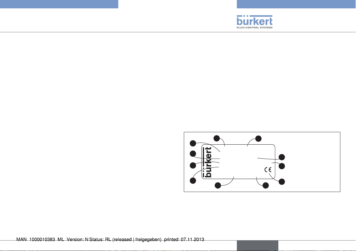
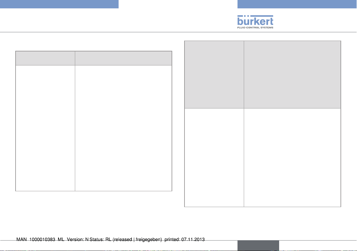
5.3 Description of the name plate on
the standard 1062
2
1
1062 PROXIMITY SWITCH
3
4
3-WIRE PNP-NO
10-30V DC NO/NC
MAX:200mA ACTUATOR >80
S/N 1199
00560409 W48LP
Made in France
5
6
Fig. 1: Name plate on the 1062 position feedback, standard
version
1. Type of device
2. Characteristics of the limit switch
3. Electrical power supply
11
10
9
8
7
english
9
Page 10
Type 1062
Description
4. Current consumption
5. Serial number
6. Item number
7. Manufacturing code
8. Conformity Marking
9. Available actuator sizes
10. Mode of operation of the 1062
11. Limit switch type
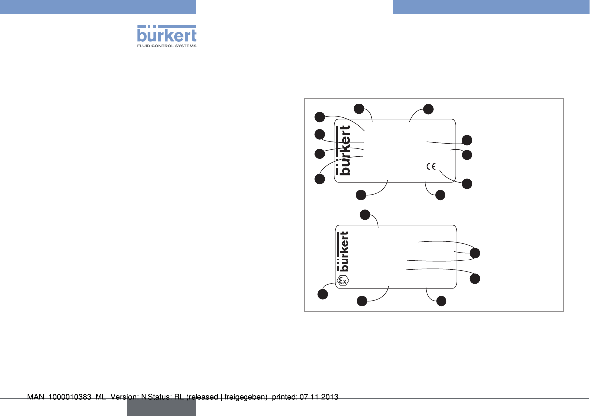
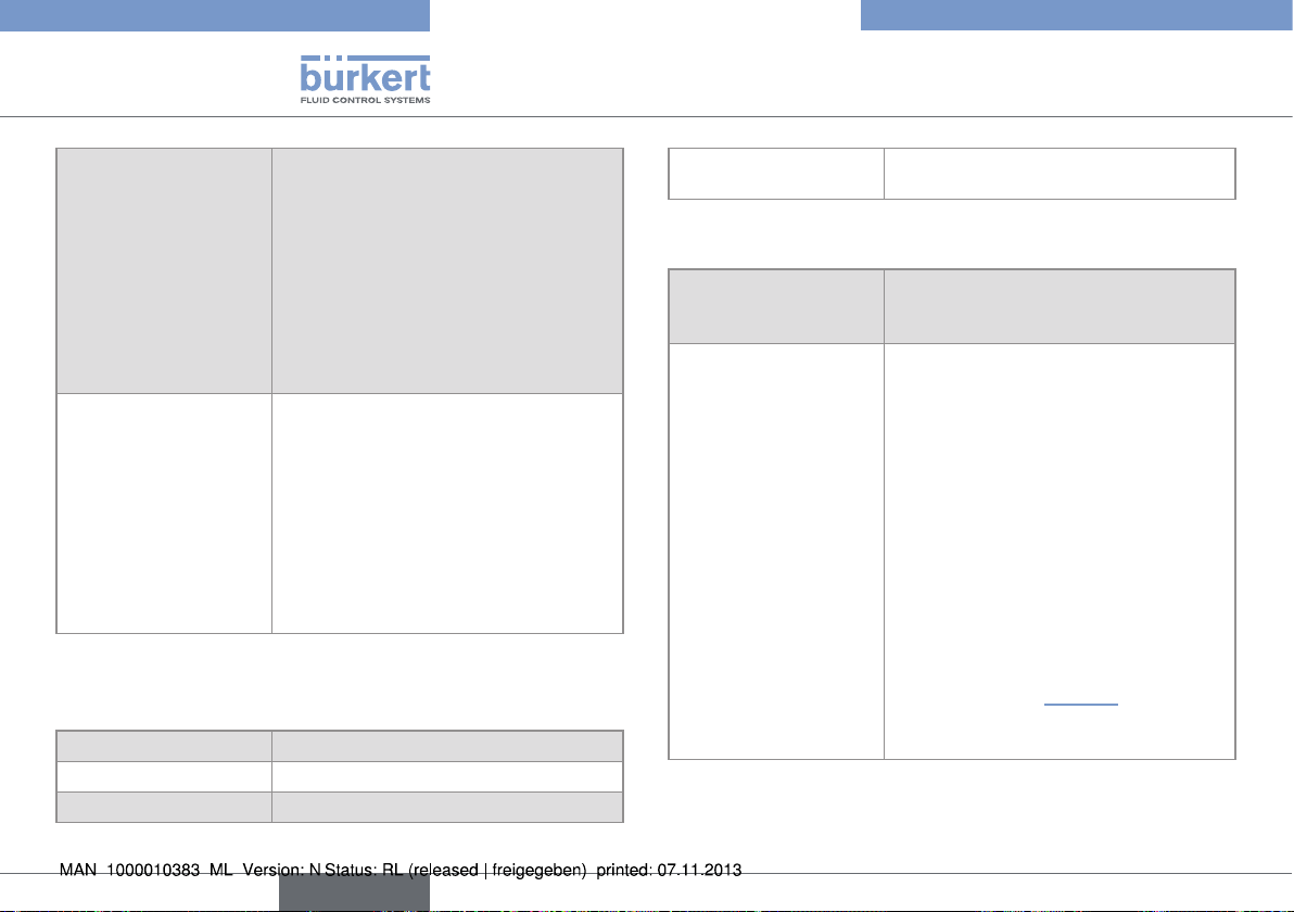
5.4 Description of the name plates
on the 1062 ATEX
2
1
1062 PROXIMITY SWITCH
3
4
5
2-WIRE NAMUR
8V DC NO/NC
MAX:15mA ACTUATOR =40
INERIS 03ATEX0268X/02
Made in France
00560411 W48LP
6
12
II 2 GD EEx Ia IIC
T6, T5 ou T4
Ex iaD21 T85°C, T100°C
ou T135°C
S/N 1000
F67220 TRIEMBACH
00560411 W48LP
13
6
Fig. 2: Name plate on the 1062 position feedback, ATEX version
1. Type of device
2. Characteristics of the limit switch
3. Electrical power supply
4. Current consumption
11
10
9
0102
8
7
15
14
7
10
english
Page 11
Type 1062
Technical data
5. ATEX certification body and certification number
6. Item number
7. Manufacturing code
8. Conformity Marking
9. Actuator size
10. Mode of operation
11. Limit switch type
12. Operating zone
13. ATEX logo
14. Serial number
15. Temperature classification
5.5 Versions available
To find out about the versions of the position feedback available,
consult the technical datasheet for the 1062 on our Internet site
under:
www.burkert.com
6 TECHNICAL DATA
6.1 Conditions of use
Ambient temperature
• version approved by CSA and CE
• version only approved by CE
Air humidity < 80%, non condensated
Protection class acc. to EN 60529 IP65, when wired and
6.2 Conformity of the 1062 ATEX to
standards and directives
The 1062 ATEX electrical position feedback (version with double
inductive 2-wire NAMUR switch) meets the requirements of the
ATEX Directive 94/9/EC on equipment intended for use in potentially explosive atmospheres. The following standards have been
used in the assessment:
• EN 60079-0 (2004)
• EN 60079-11 (2006)
• EN 61241-0 (2006)
• EN 61241-11 (2007)
• 0 to +60 °C
• -20 to +60 °C
cable gland tightened
english
11
Page 12
Type 1062
Technical data
6.3 Conformity of the 1062 approved
by CSA
The devices approved by CSA, with variable key PD01, conform to
the following standards:
• CSA C22.2 n° 61010-1-04
• UL 61010-1
6.4 General technical data
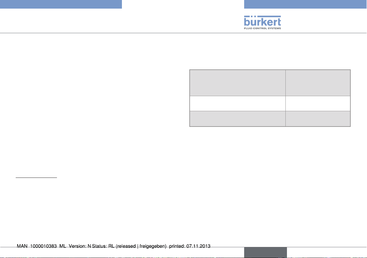
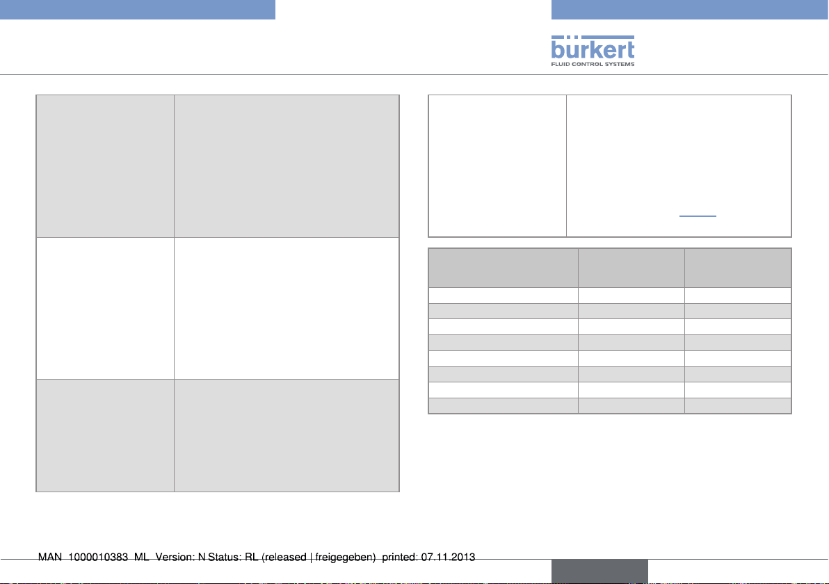
6.4.1 Mechanical data
PC or PSU
EPDM
PA6 or PPS
PA or PVDF
Fig. 3: Materials used in the 1062 position feedback
Component Material
Housing / Cover PA6 / PC or
PPS/PSU
Stainless steel or
brass
Brass
Component Material
Seal between the cover and the
EPDM
housing
Cable gland M16x1,5 PA or PVDF
External threaded part Brass or stainless steel
Internal threaded part Brass
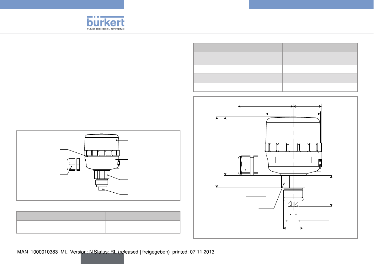
67,5 35
Ø 66
72
87
M16x1,5
SW27
M5 / M6 / M10
12 / 10 / 16
M24x1,5 / M26x1,5 / M36x2
24 - 40
12
Fig. 4: Dimensions of the 1062 position feedback [mm]
english
Page 13
Type 1062
Technical data
6.4.2 General data
Actuator size Ø 40 to 125 mm, depending on the
version
Mechanical contact
version
• type of contact
• statuses detected
- 1062 fitted with
one switch
- 1062 fitted with
two switches
• valve open or closed
indication mode
• colour of the lights
depending on the
status detected
• power up light
• in silver or gold
- valve open or valve closed
- valve open and valve closed
• using lights and electrical signal via
terminal block
• a green light comes on when the valve
opens ("position open" or "position
open and closed" version) and/or a
red light comes on when the valve
closes ("position closed" or "position
open and closed" version)
• orange
Version with inductive
2-wire switch
• statuses detected
- 1062 fitted with
one switch
- 1062 fitted with
two switches
• valve open or closed
indication mode
Version with inductive
3-wire switch
• statuses detected
- 1062 fitted with
one switch
- 1062 fitted with
two switches
• valve open or closed
indication mode
• colour of the lights
depending on the
status detected
• power up light
- valve open or valve closed
- valve open and valve closed
• by electrical signal via terminal block
- valve open or valve closed
- valve open and valve closed
• using lights and electrical signal via
terminal block
• a green light comes on when the valve
opens and a red light comes on when
the valve closes
• orange
english
13
Page 14
Type 1062
Technical data
Version with double
inductive switch (4-wire)
• statuses detected
• valve open or closed
indication mode
• colour of the lights
depending on the
status detected
• power up light
Version with double
inductive 2-wire NAMUR
switch
• statuses detected
• valve open or closed
indication mode
• colour of the lights
depending on the
status detected
• valve open and valve closed
• using lights and electrical signal via
terminal block
• an orange light comes on when the
valve opens and a red light comes on
when the valve closes
• green
• valve open and valve closed
• using lights and electrical signal via
terminal block
• an orange light goes off when the
valve opens and a red light goes off
when the valve closes
6.4.3 General data specific to the devices
approved by CSA
Degree of pollution Degree 2, acc. to EN 61010-1
Installation category Category I, acc. to EN 61010-1
Height above sea level max. 2000 m
Electric power supplied by an SELV (Safety Extra Low
Voltage) source
6.4.4 Electrical data
Connection cable standard, diameter between 5 and
7 mm, max cross-section of the strand
2
1 mm
Mechanical contact
version (per contact)
• Power supply of
devices approved by
CSA and CE
• Power supply
of devices only
approved by CE
• Power consumption
• Allowable load
• Type of output
• 12-30 V AC or
12-48 V DC
• 12-30 V DC or
12-48 V DC/V AC or
48/110 V DC/V AC or
110/250 V DC/V AC
• < 35 mA (48 V DC)
< 8 mA (220 V AC)
• depending on the power supply
voltage and the type of load, inductive
or resistive: see „Table 1“ next page
• contact normally open or normally
closed
14
english
Page 15
Type 1062
Technical data
Version with inductive
2-wire switch (per
switch)
• Power supply
• Power consumption
• Allowable load
• Type of output
Version with inductive
3-wire switch (per
switch)
• Power supply
• Power consumption
• Allowable load
• Type of output
Version with double
inductive 4-wire switch
• Power supply
• Power consumption
• Allowable load
• Type of output
• 10-30 V DC
• ≤ 2 mA
• ≤ 100 mA
• contact normally open or normally
closed
• 10-30 V DC
• ≤ 25 mA
• ≤ 200 mA
• NPN or PNP, normally open or normally closed
• 10-30 V DC
• ≤ 15 mA
• ≤ 150 mA, per output
• PNP, normally open
Version with double
inductive 2-wire
NAMUR switch
• Power supply
• Power consumption
• 8 V DC
• ≤ 1,2 mA (activated) and
> 2,1 mA (not activated)
• Allowable load
• Type of output
Supply voltage
• see table in chap. „8.2.5“
• acc. to NAMUR
Inductive load
[I
]
max
Resistive load
[I
max
]
24 V DC 5 A 5 A
30 V DC 2 A 5 A
50 V DC 0,7 A 1 A
74 V DC 0,25 A 0,6 A
125 V DC 0,03 A 0,4 A
250 V DC 0,02 A 0,25 A
125 V AC 8 A 8 A
250 V AC 8 A 8 A
Table 1: Allowable loads for a mechanical contact version
english
15
Page 16
Type 1062
Assembly
7 ASSEMBLY
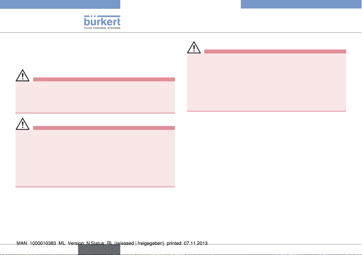
7.1 Safety instructions
Risk of explosion.
When the 1062 is used in an ATEX 21 or 22 zone, make sure:
• That the cover of the electrical position feedback is always
screwed shut before operating the valve.
danger
Danger due to high pressure in the installation.
▶ Shut down the pneumatic power source and depressurise the
pipes before carrying out work on the device.
Risk of injury due to electrical discharge.
▶ Shut down the electrical power source of all the conductors and
isolate it before carrying out work on the system.
▶ Observe all applicable accident protection and safety regula-
tions for electrical equipment.
Warning
Risk of injury due to non-conforming assembly.
▶ The device must only be assembled by qualified and skilled staff
with the appropriate tools.
Risk of injury due to unintentional switch on of power supply
or uncontrolled restarting of the installation.
▶ Avoid unintentional activation of the installation.
▶ Guarantee a set or controlled restarting of the process subse-
quent to the assembly of the device.
16
english
Page 17
Type 1062
Assembly
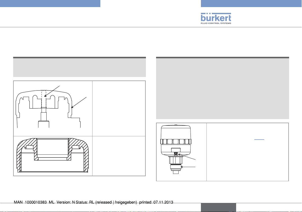
7.2 Replacing the top part of an
actuator size 40mm
note
The tightness of the actuator is not guaranteed when the
cover is removed.
▶ Prevent the projection of fluids into the actuator.
B
→ Remove the top part
of the actuator, "A",
by unscrewing it with
A
the spanner available
in accessories (item
number 639175).
→ Remove the top part
of the actuator rod,
"B", by unscrewing by
hand.
→ Screw the top part of
the actuator supplied
with the 1062 to the
actuator size 40mm,
and tighten it using the
spanner (item number
639175).
Fig. 5: Replacing the top part of the actuator size 40mm
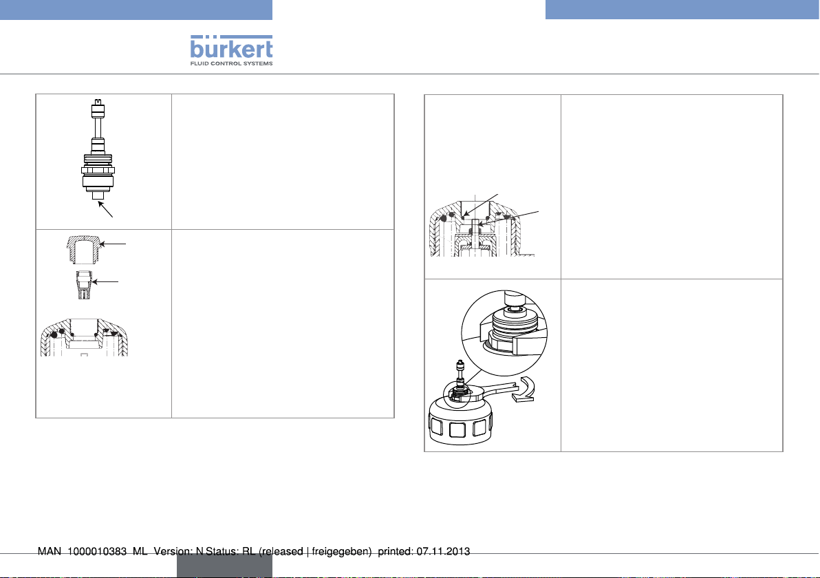
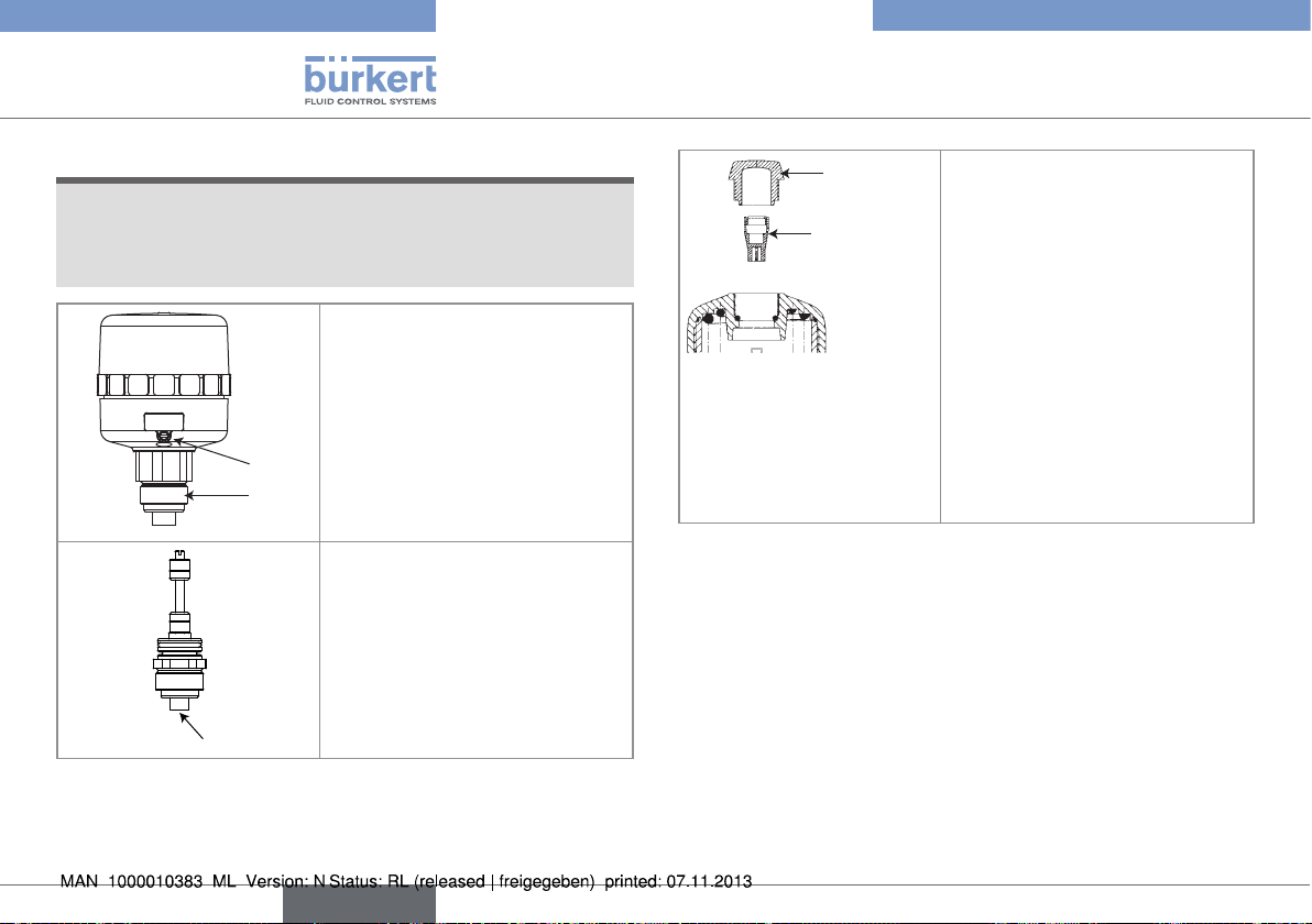
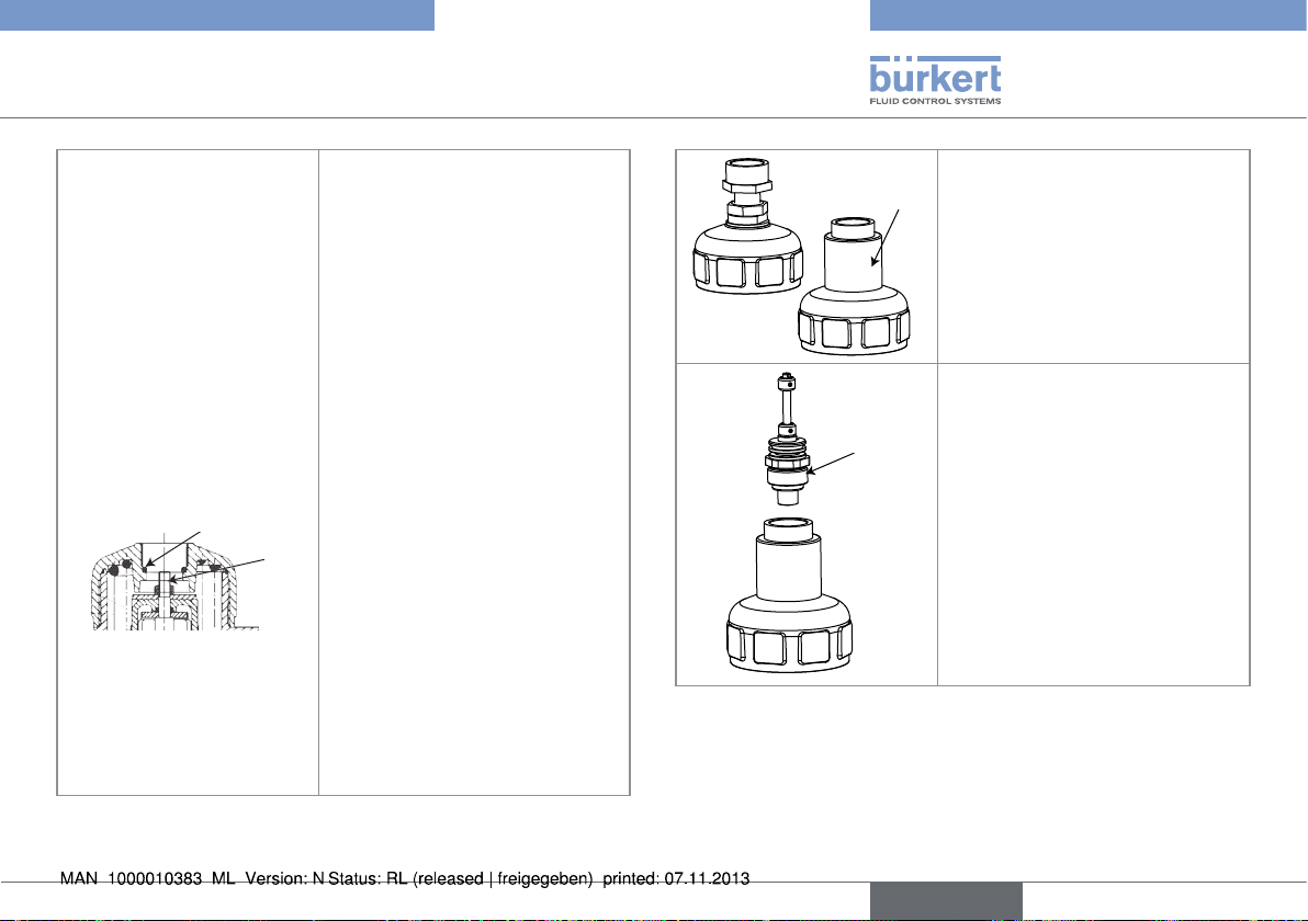
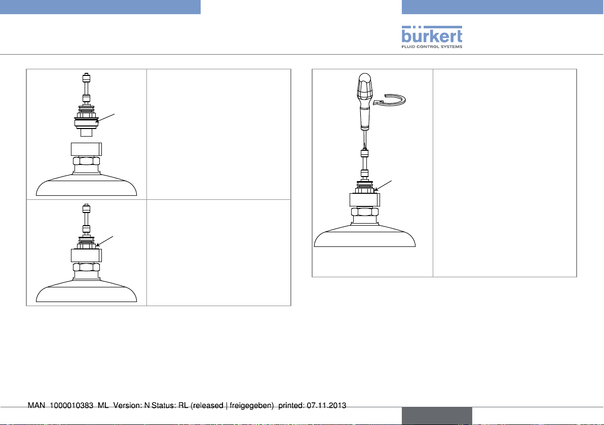
7.3 Fitting the position feedback to a
pneumatic actuator
note
The tightness of the actuator is not guaranteed when the
transparent cap is removed.
▶ Prevent the projection of fluids into the actuator.
The tightness of the position feedback is not guaranteed
when the cover is removed.
▶ Prevent the projection of fluids into the position feedback.
The position feedback may be damaged if a metal component comes into contact with the electronics.
▶ Prevent contact of the electronics with a metal component (a
screwdriver, for example).
→ If the valve is fitted with an actuator
size 40mm, replace the top part of the
actuator. See chap. „7.2“.
→ Unscrew the cone point set screw "C"
from the 1062 to unlock the duplication system "D" using a hexagonal
C
D
male spanner.
→ Carefully remove the duplication
system "D" from the housing of the
1062.
english
17
Page 18
Type 1062
D
J
E
H
Assembly
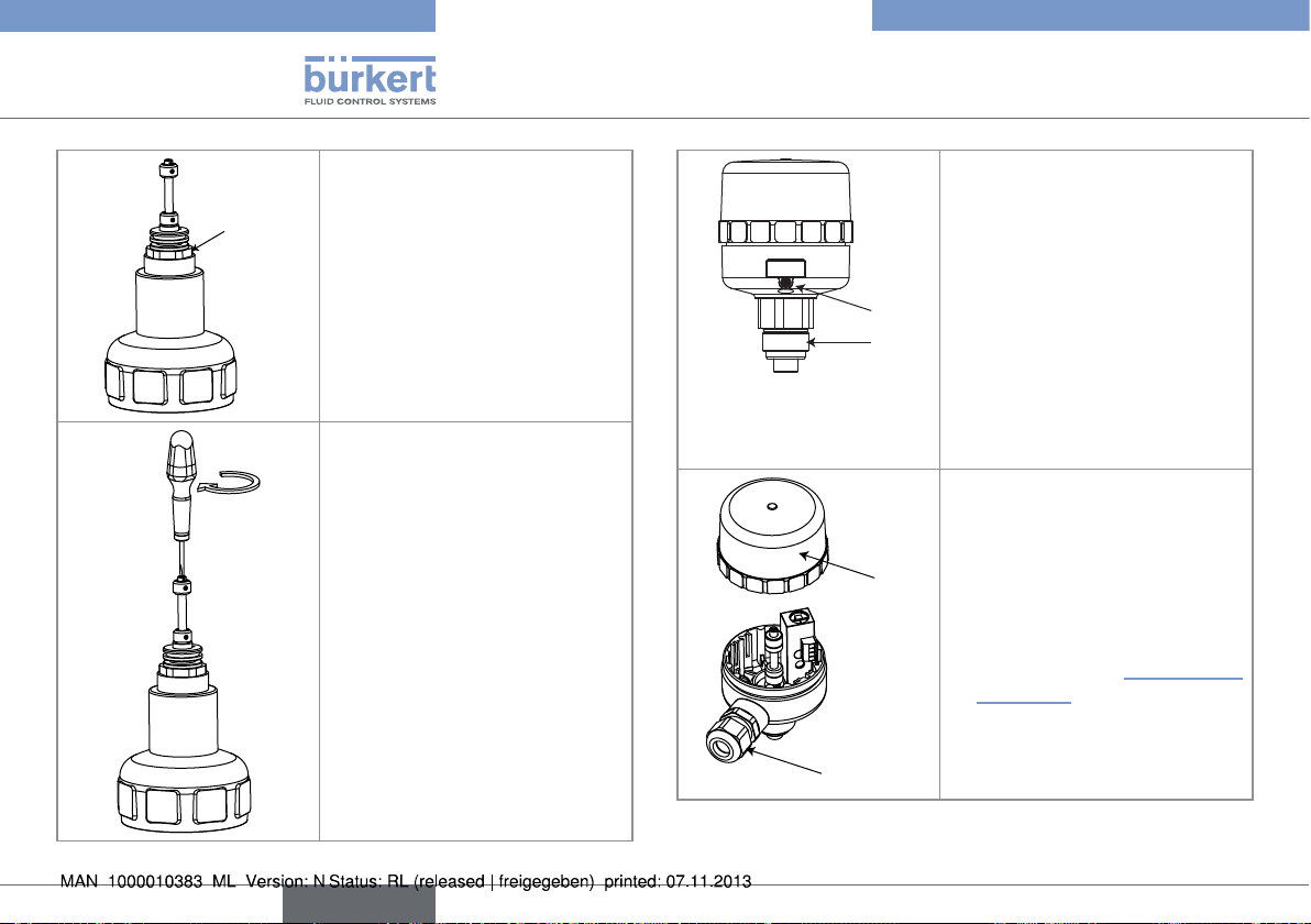
→ Check that the seals have been fitted
and that they are undamaged. Replace
them if necessary.
→ Put thread lock into the internal thread
in the duplication rod "E".
→ Check that the seal "H" is fitted and
that it is correctly positioned inside
the actuator.
→ Insert the duplication system "D" into
the actuator.
→ Screw the duplication rod "E" onto
the actuator rod "J".
E
F
G
→ Unscrew the small transparent cap "F"
on the actuator, preferably by hand or
using a suitable tool in order not to
damage it (except for actuators size
40mm).
→ Pump air into the actuator on a valve
which is normally closed (function "A")
or has a double effect (function "I") so
that the actuator rod moves to the top
position.
→ Tighten the adaptor until free contact
is obtained with the top of the
actuator, using a flat No 27 spanner.
→ Unscrew the visual position feedback
"G" using a hexagonal male spanner.
18
english
Page 19
Type 1062
Assembly
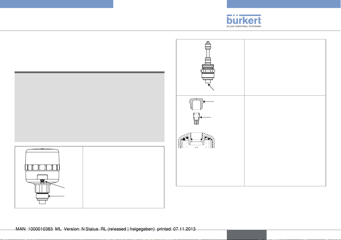
→ Fully tighten the duplication rod on
the actuator rod using a screwdriver
with a blade of suitable size.
→ Depressurize the actuator of a valve
which is normally closed (function
"A") or has a double effect (function
"I"): the valve recovers its default
position.
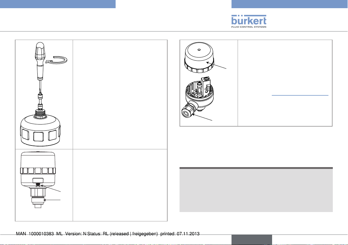
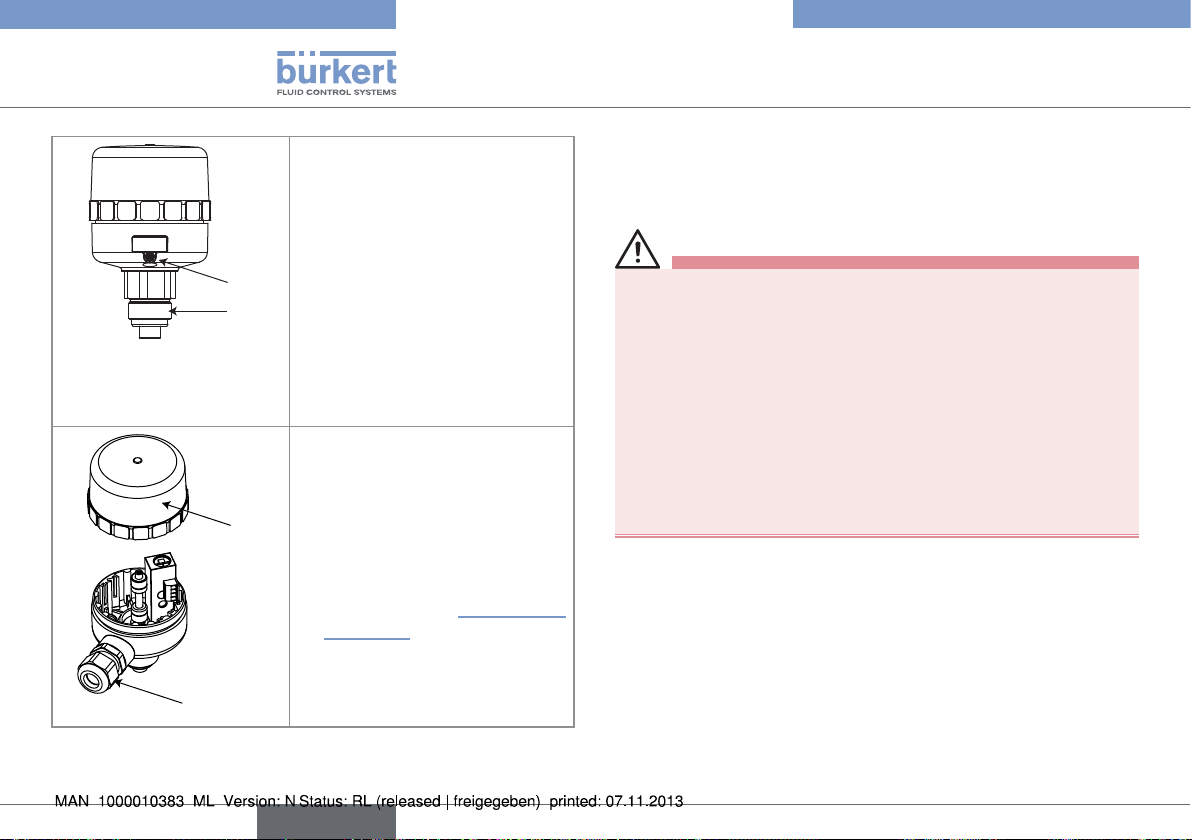
K
→ Unscrew the cover "K" on the
position feedback.
→ Unscrew the cable gland "L".
→ Thread the cable through the cable
gland.
→ Wire according to the wiring
diagram for your version of the 1062:
See chap. „8 Installation and wiring“.
→ Fasten the cable gland to ensure
tightness of the product.
L
7.4 Fitting the position feedback with
stroke limiter to a pneumatic
→ Insert the position feedback housing
into the duplication system "D"
setting the cable gland in the
direction desired and making sure,
on a mechanical contact version,
that you do not damage the contact
C
D
levers on the switches.
→ Fasten the housing and the dupli-
cation system by tightening the cone
point set screw "C" using a hexagonal male spanner.
note
The tightness of the actuator is not guaranteed when the
transparent cap is removed.
▶ Prevent the projection of fluids into the actuator.
The tightness of the position feedback is not guaranteed
when the cover is removed.
▶ Prevent the projection of fluids into the position feedback.
actuator size 50 to 80mm
english
19
Page 20
Type 1062
Assembly
note
The position feedback may be damaged if a metal component comes into contact with the electronics.
▶ Prevent contact of the electronics with a metal component (a
screwdriver, for example).
→ Unscrew the cone point set
screw "C" from the 1062 to
unlock the duplication system "D"
using a hexagonal male spanner.
→ Carefully remove the duplication
system "D" from the housing of
C
D
the 1062.
→ Check that the seals have
been fitted and that they are
undamaged. Replace them if
necessary.
→ Put thread lock into the internal
thread in the duplication rod "E".
E
F
G
→ Unscrew the small transparent
cap "F" on the actuator, preferably by hand or using a suitable tool in order not to damage
it (except for actuators size
40mm).
→ Pump air into the actuator on a
valve which is normally closed
(function "A") or has a double
effect (function "I") so that the
actuator rod moves to the top
position.
→ Unscrew the visual position
feedback "G" using a hexagonal
male spanner.
20
english
Page 21
Type 1062
O
H
J
N
K
P
M
Assembly
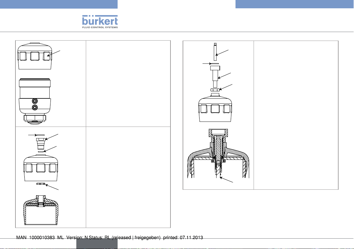
→ Check that the seal "H" is fitted
and that it is correctly positioned inside the actuator.
P
→ Insert the protection hood "P".
→ Screw the adapter nut "J" in the
top part of the actuator.
→ Screw the connecting pin "K"
with locknut "L" in the adapter
nut "J".
→ Adjust the stroke of the actuator
(by more or less screwing the
connecting pin "K") depending
on the operating mode of the
valve:
- if the valve operates as normally closed (NC), adjust
the stroke by starting valve
closed.
- if the valve operates as normally open (NO), adjust the
stroke by starting valve open.
D
→ Insert the duplication system
"D" into the stroke limiter.
→ Block the locknut "L".
→ Insert the seal "M" in the con-
necting pin "K".
→ Screw the stem "N" on the
stem "O" of the actuator.
english
21
Page 22
Type 1062
Assembly
→ Tighten the duplication
system "D" until free contact
D
is obtained with the top of
the limiter, using a flat No 27
spanner.
C
D
→ Insert the position feedback
housing into the duplication
system "D" setting the
cable gland in the direction
desired and making sure, on
a mechanical contact version,
that you do not damage the
contact levers on the switches.
→ Fasten the housing and the
duplication system by tightening the cone point set screw
→ Fully tighten the duplication
rod on the actuator rod using
a screwdriver with a blade of
suitable size.
→ Depressurize the actuator of a
valve which is normally closed
(function "A") or has a double
effect (function "I"): the valve
recovers its default position.
Q
"C" using a hexagonal male
spanner.
→ Unscrew the cover "Q" on the
position feedback.
→ Unscrew the cable gland "R".
→ Thread the cable through the
cable gland.
→ Wire according to the wiring
diagram for your version of the
1062: See chap. „8 Installation
and wiring“.
→ Fasten the cable gland to
ensure tightness of the product.
R
22
english
Page 23
Type 1062
E
Assembly
7.5 Fitting the position feedback with
stroke limiter to a pneumatic
actuator size 100 or 125mm
note
The tightness of the actuator is not guaranteed when the
transparent cap is removed.
▶ Prevent the projection of fluids into the actuator.
The tightness of the position feedback is not guaranteed
when the cover is removed.
▶ Prevent the projection of fluids into the position feedback.
The position feedback may be damaged if a metal component comes into contact with the electronics.
▶ Prevent contact of the electronics with a metal component (a
screwdriver, for example).
→ Unscrew the cone point set
screw "C" from the 1062 to
unlock the duplication system "D"
using a hexagonal male spanner.
→ Carefully remove the duplication
system "D" from the housing of
C
D
the 1062.
→ Check that the seals have
been fitted and that they are
undamaged. Replace them if
necessary.
→ Put thread lock into the internal
thread in the duplication rod "E".
F
G
→ Unscrew the small transparent
cap "F" on the actuator, preferably by hand or using a suitable tool in order not to damage
it
→ Pump air into the actuator on a
valve which is normally closed
(function "A") or has a double
effect (function "I") so that the
actuator rod moves to the top
position.
→ Unscrew the visual position
feedback "G" using a hexagonal
male spanner.
english
23
Page 24
Type 1062
Assembly
H
M
K
J
actuator, by unscrewing it with
the spanner available in accessories (item number 639172 for
an actuator size 100mm or item
number 639173 for an actuator
size 125mm).
→ Insert the seal "J" into the groove
of the adaptater nut "K".
→ Screw the adaptater nut "K" in
the top part of the actuator.
P
→ Remove the top part "H" of the
Q
N
O
→ Screw the locknut "L" on "K",
inside the top hat of the actuator.
→ Insert the seal "M" into the adap-
tater nut "K".
L
→ Screw back the top part of the
actuator.
R
→ Screw the connecting pin "N"
with the locknut "O" in the
adapter nut "K".
→ Adjust the stroke of the actuator
(by more or less screwing the
connecting pin "N") depending
on the operating mode of the
valve:
- if the valve operates as normally closed (NC), adjust
the stroke by starting valve
closed.
- if the valve operates as normally open (NO), adjust the
stroke by starting valve open.
→ Block the locknut "O".
→ Insert the seal "P" in the con-
necting pin "N".
→ Screw the stem "Q" on the
stem "R" of the actuator.
24
english
Page 25
Type 1062
Assembly
→ Insert the duplication system
"D" into the stroke limiter.
D
→ Fully tighten the duplication
rod on the actuator rod using
a screwdriver with a blade of
suitable size.
→ Depressurize the actuator of a
valve which is normally closed
(function "A") or has a double
effect (function "I"): the valve
recovers its default position.
D
→ Tighten the duplication
system "D" until free contact
D
is obtained with the top of
the limiter, using a flat No 27
spanner.
english
25
Page 26
Type 1062
Installation and wiring
→ Insert the position feedback
housing into the duplication
system "D" setting the
cable gland in the direction
desired and making sure, on
a mechanical contact version,
C
D
that you do not damage the
contact levers on the switches.
→ Fasten the housing and the
duplication system by tightening the cone point set screw
"C" using a hexagonal male
spanner.
→ Unscrew the cover "R" on the
position feedback.
→ Unscrew the cable gland "S".
R
→ Thread the cable through the
cable gland.
8 INSTALLATION AND WIRING
8.1 Safety instructions
Risk of explosion.
When the 1062 is used in an ATEX 21 or 22 zone, make sure:
• That the cover of the electrical position feedback is always
screwed shut before operating the valve.
• That you check that the device is not subject to a flow of air and
dust that may result in an accumulation of electrostatic charges.
Otherwise, intall the device in a conductive cover.
• "The NAMUR switches on the 1062 must be powered by a voltage
source of a type certified for use in explosive atmospheres in
groups IIB/IIC and their combination must be compatible from the
instrinsic safety point of view."
→ Wire according to the wiring
diagram for your version of the
1062: See chap. „8 Installation
and wiring“.
→ Fasten the cable gland to
ensure tightness of the product.
S
26
english
Page 27
Type 1062
Installation and wiring
danger
Danger due to high pressure in the installation.
▶ Shut down the pneumatic power source and depressurise the
pipes before carrying out work on the device.
Risk of injury due to electrical discharge.
▶ Shut down the electrical power source of all the conductors and
isolate it before carrying out work on the system.
▶ Observe all applicable accident protection and safety regula-
tions for electrical equipment.
Warning
Risk of injury due to nonconforming installation.
▶ Electrical installation can only be carried out by qualified and
skilled staff with the appropriate tools.
▶ Install appropriate safety devices (correctly rated fuse and/or
circuit-breaker).
Risk of injury due to unintentional switch on of power supply
or uncontrolled restarting of the installation.
▶ Take appropriate measures to avoid unintentional activation of
the installation.
▶ Guarantee a set or controlled restarting of the process subse-
quent to the assembly of the device.
8.2 Electrical wiring
danger
Risk of injury due to electrical discharge.
▶ Shut down the electrical power source of all the conductors and
isolate it before carrying out work on the system.
▶ Observe all applicable accident protection and safety regula-
tions for electrical equipment.
Use a high quality electrical power supply (filtered and
regulated).
note
The tightness of the position feedback is not guaranteed
when the cover is removed.
▶ Prevent the projection of fluids into the position feedback.
The position feedback may be damaged if a metal component comes into contact with the electronics.
▶ Prevent contact of the electronics with a metal component (a
screwdriver, for example).
→ Assemble the device as shown in chap. „7 Assembly“ before
wiring it.
→ Carry out the electrical wiring in accordance with chap. „8.2.1“
to „8.2.6“ for your version of the 1062.
→ Once the device has been wired, lock the cable so that it does
not impair the mobility of the duplication rod, by inserting it
english
27
Page 28
Type 1062
1062
Installation and wiring
into the notches provided for this purpose in the bottom of the
housing, as shown in „Fig. 6“ below:
Fig. 6: Final position of the cable
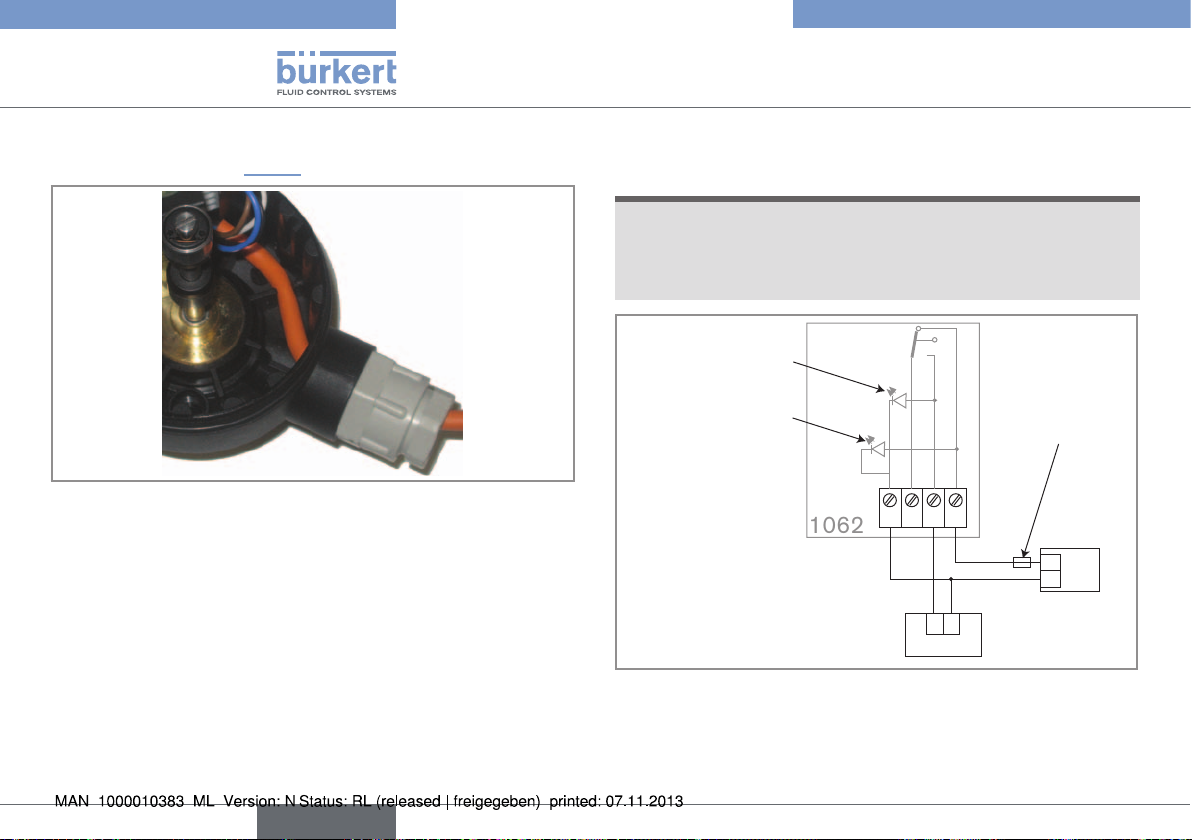
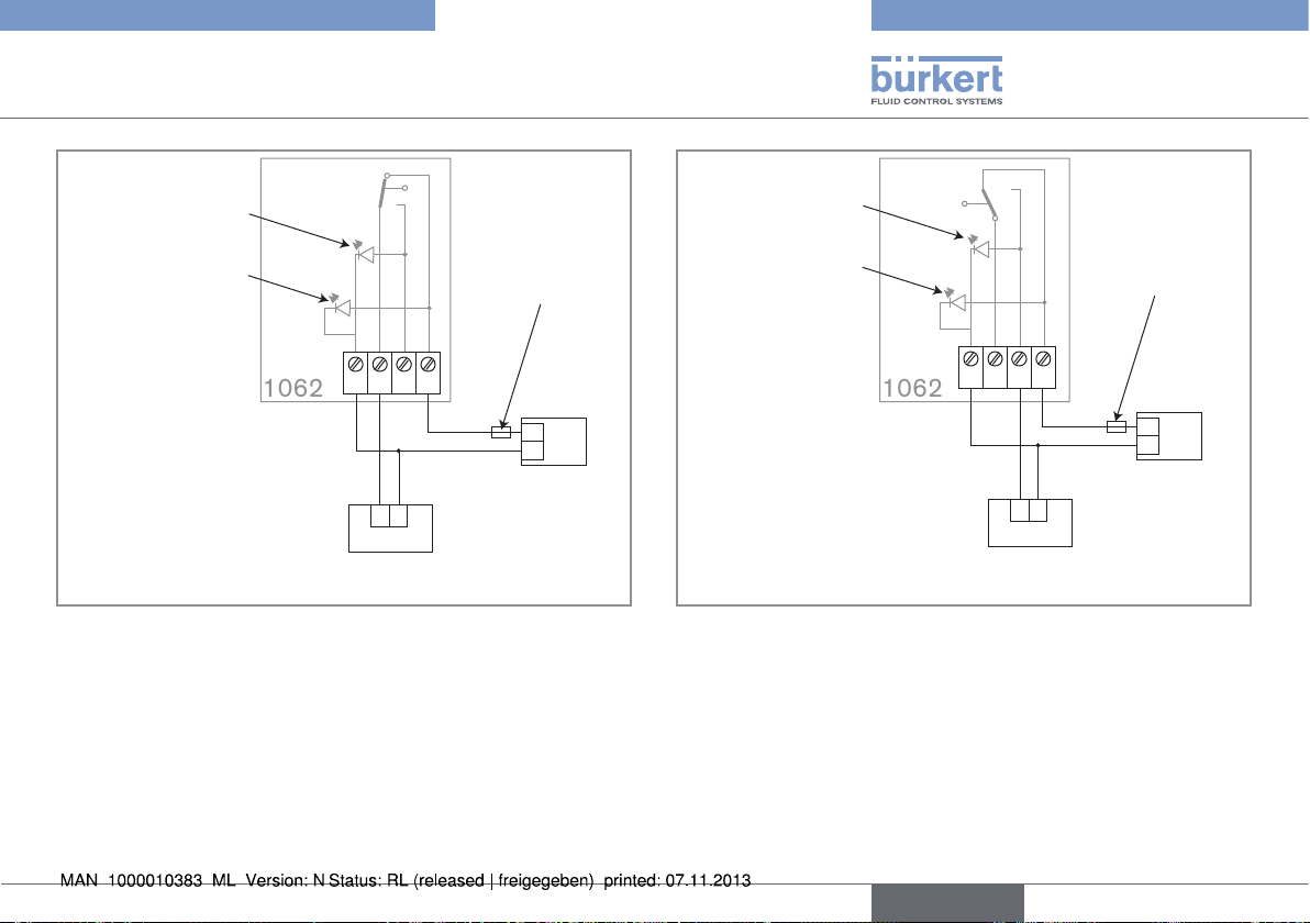
8.2.1 Wiring a mechanical contact version
note
On a mechanical contact version, the used contact is not
voltage free.
• Do not connect the unused contact in order to obviate any danger
of malfunction.
Green light (open
valve detection)
Orange light (volt-
age present)
-
NONC
Load
+
8 A max.
Fig. 7: Wiring of the contact when normally open (NO) on a
mechanical contact version, valve open detection
1)
Use a power supply that matches the data shown on the name plate of the
1062
Fuse suitable for
the max. load
+
Power supply
-
+
-
1)
28
english
Page 29
Type 1062
1062
1062
Installation and wiring
Green light (open
valve detection)
Orange light (volt-
age present)
-
+
8 A max.
NONC
-
Fuse suitable for
the max. load
+
Power supply
+
-
1)
Load
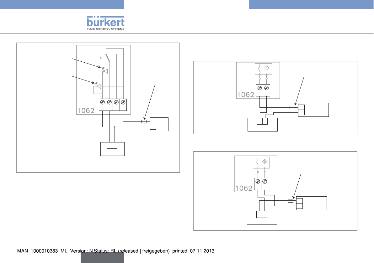
Fig. 8: Wiring of the contact when normally closed (NC) on a
mechanical contact version, valve open detection
1)
Use a power supply that matches the data shown on the name plate of the
1062
Red light
(valve closed
detection)
Orange light
(voltage present)
-
NONC
+
8 A max.
Fuse suitable for
the max. load
+
Power supply
-
+
-
1)
Load
Fig. 9: Wiring of the contact when normally open (NO) on a
mechanical contact version, valve closed detection
1)
Use a power supply that matches the data shown on the name plate of the
1062
english
29
Page 30
1062
Red light (valve closed
1062
1062
detection)
Orange light (volt-
age present)
-
+
8 A max.
NONC
-
Fuse suitable for
the max. load
+
Power supply
+
-
1)
Load
Fig. 10: Wiring of the contact when normally closed (NC) on a
mechanical contact version, valve closed detection
1)
Use a power supply that matches the data shown on the name plate of the
1062
Type 1062
Installation and wiring
8.2.2 Wiring a version with inductive
2-wire switch
Reaction speed according
to the max. load
-
+
125 mA
Load
-
+
100 mA max.
Fig. 11: Wiring the inductive 2-wire switch in "less common"
mode, open and/or closed valve detection
-
+
125 mA
Load
-
+
100 mA max.
+
10-30 VDC
-
Power supply
Reaction speed according
to the max. load
+
10-30 VDC
-
Power supply
30
Fig. 12: Wiring the inductive 2-wire switch in "more common"
mode, open and/or closed valve detection
english
Page 31

Type 1062
1062
1062
Installation and wiring
8.2.3 Wiring a version with inductive
3-wire switch
Green light (valve open detection) or red
light (valve closed detection)
Orange light
(voltage present)
Reaction speed according
to the max. load
A
+ -
250 mA
Load
-
+
200 mA max.
Fig. 13: Wiring a version with an inductive 3-wire switch in PNP
mode, valve open or valve closed detection
+
10-30 VDC
-
Power supply
8.2.4 Wiring a version with two inductive
3-wire switches
Green light (valve open
detection)
A
+ -
Valve open
switch
-
+
200 mA max.
Load 1
Fig. 14: Wiring a version with two inductive 3-wire switches in
NPN mode, valve open and valve closed detection
Red light (valve closed
detection)
A
+ -
Reaction speed according
to the max. load
500 mA
-
+
200 mA max.
Load 2
Valve closed
switch
Orange light
(voltage present)
+
10-30 VDC
-
Power supply
english
31
Page 32

Type 1062
062
Installation and wiring
Green light (valve open
detection)
Red light (valve closed
detection)
Valve closed
switch
Orange light
(voltage present)
500 mA
+
10-30 VDC
-
1
Valve open
switch
A
+ -
A
+ -
Reaction speed according
to the max. load
Power supply
-
+
200 mA max.
Load 1
-
+
200 mA max.
Load 2
Fig. 15: Wiring a version with two inductive 3-wire switches in
PNP mode, valve open and valve closed detection
8.2.5 Wiring a version with double
inductive 2-wire NAMUR switch
Respect the maximum allowable characteristics of the circuit
established with an inductive NAMUR switch shown in the table
below.
Max. authorised
ambient T°
100 °C II 2G T4 60 200 20 180 350
85 °C II 2G T5 60 200 20 180 350
80 °C II 2G T5 60 200 20 180 350
70 °C II 2G T6 60 200 20 180 350
Category
T° class
Ii [mA] (with
resistive limit)
Pi (mW)
U (V)
Ci (nF)
Li (µH)
32
english
Page 33

Type 1062
Installation and wiring
The following table gives the state of the orange and red LEDs and
the related position of the valve, depending on the use of the S01
and S02 circuits:
Circuits S01 and
S02
Circuits S01 and
S02 are wired and
energized
LEDs Valve position
Open Closed
Orange LED
state (S01)
Red LED
state (S02)
Only circuit S01
wired and energized
Orange LED
state (S01)
Red LED
state (S02)
Only circuit S02
wired and energized
Orange LED
state (S01)
Red LED
state (S02)
: LED OFF
: LED ON
Orange light (valve open
detection)
S01
4
S02
3
UB2
2
S01
1
UB1
S02
Red light (valve closed
detection)
In
+
In
+
Intrinsic safety barrier
Fig. 16: Wiring the 2 outputs of the double inductive 2-wire
switch, valve open detection (output S01) and valve
closed detection (output S02)
english
33
Page 34

Type 1062
Commissioning
8.2.6 Wiring a version with double
inductive 4-wire switch
Orange light (valve open detection)
Green light
(voltage
present)
S01
S02
Fig. 17: Wiring the 2 outputs of a version with a double inductive
4-wire switch, in PNP mode, valve open detection (output
S01) and/or valve closed detection (output S02)
Red light (valve closed detection)
Load 2
150 mA max.
4
S02
3
0V
2
S01
1
V+
+
150 mA max.
Load 1
+
-
Reaction speed
according to the
max. load
500 mA
+
10-30 VDC
-
Power supply
-
9 COMMISSIONING
9.1 Safety instructions
Warning
Danger due to nonconforming commissioning.
Nonconforming commissioning could lead to injuries and damage
the device and its surroundings.
▶ Before commissioning, make sure that the staff in charge have
read and fully understood the contents of the manual.
▶ In particular, observe the safety recommendations and intended
use.
▶ The device/installation must only be commissioned by suitably
trained staff.
▶ Protect the device against electromagnetic interference and
ultraviolet rays.
Protect this device against electromagnetic interference, ultraviolet rays and, when installed outdoors,
the effects of climatic conditions.
9.2 Setting the cams
Activate the valve to check the correct detection of the open and/or
closed position.
If detection is incorrect, reposition each cam opposite its switch
according to the position of the valve as shown in the photos in „Fig.
17“.
34
english
Page 35

Type 1062
Maintenance and troubleshooting
→ Activate the valve
Target of the valve
open switch
so that it opens
completely.
→ The top cam
should be located
opposite the
target of the valve
open switch.
→ Activate the valve
so that it closes
completely.
→ The bottom cam
should be located
opposite the
target of the valve
Target of the valve
closed switch
Fig. 18: Correct position of the cams in relation to the switches
closed switch.
10 MAINTENANCE AND
TROUBLESHOOTING
10.1 Safety instructions
danger
Danger due to high pressure in the installation.
▶ Shut down the pneumatic power source and depressurise the
pipes before carrying out work on the device.
Risk of injury due to electrical discharge.
▶ Shut down the electrical power source of all the conductors and
isolate it before carrying out work on the system.
▶ Observe all applicable accident protection and safety regula-
tions for electrical equipment.
Warning
Risk of injury due to non-conforming maintenance.
▶ Maintenance must only be carried out by qualified and skilled
staff with the appropriate tools.
▶ Guarantee a set or controlled restarting of the process, after a
power supply interruption.
10.2 Cleaning of the transmitter
The external surface of the electrical position feedback can be
cleaned with a cloth dampened with water or a product compatible
with the materials from which it is made.
english
35
Page 36

Type 1062
Spare parts and accessories
Please feel free to contact your Bürkert supplier for any additional
information.
11 SPARE PARTS AND
ACCESSORIES
Caution
Risk of injury and damage by the use of incorrect parts.
Incorrect accessories or unsuitable replacement parts may cause
injuries and damage the device and the surrounding area.
▶ Use only original accessories and original replacement parts
from Bürkert.
Accessory Item number
Assembly spanner (actuator size 40mm) 639175
Assembly spanner (actuator size 100mm) 639172
Assembly spanner (actuator size 125mm) 639173
15. PACKAGING, TRANSPORT
note
Damage due to transport
Transport may damage an insufficiently protected device.
▶ Transport the device in shock-resistant packaging and away
from humidity and dirt.
▶ Do not expose the device to temperatures outside the storage
temperature range.
▶ Protect the electrical interfaces by using protection caps.
36
english
Page 37

Type 1062
Storage
12 STORAGE
note
Poor storage can damage the device.
▶ Store the device in a dry place away from dust.
▶ Storage temperature of the devices approved by CSA and CE:
0 to +60°C.
▶ Storage temperature of the devices only approved by CE:
-20 to +60°C.
16. DISPOSAL OF THE PRODUCT
→
Dispose of the device and its packaging in an environmentallyfriendly way.
note
Damage to the environment caused by products contaminated by fluids.
▶ Keep to the existing provisions on the subject of waste disposal
and environmental protection.
Please note
Comply with the national and/or local regulations which
concern the area of waste disposal.
english
37
Page 38

Type 1062
38
english
Page 39

Typ 1062
Inhaltsverzeichnis
1. DIE BEDIENUNGSANLEITUNG ..............................................................5
1.1. Darstellungsmittel .............................................................................5
1.2. Begriffsdefinition "Gerät" ............................................................... 5
2. BESTIMMUNGSGEMÄSSE VERWENDUNG .....................................6
2.1. Beschränkungen ................................................................................ 6
2.2. Ex-Zulassung ....................................................................................... 6
3. GRUNDLEGENDE SICHERHEITSHINWEISE ................................... 7
4. ALLGEMEINE HINWEISE ............................................................................ 8
4.1. Herstelleradresse und internationale Kontaktadressen 8
4.2. Gewährleistung ................................................................................... 8
4.3. Informationen im Internet .............................................................. 8
5. BESCHREIBUNG ............................................................................................ 9
5.1. Anwendungsbereich.........................................................................9
5.2. Allgemeine Beschreibung ............................................................. 9
5.2.1. Aufbau ......................................................................................9
5.2.2. Funktionsprinzip .....................................................................9
5.3. Beschreibung des Typschilds des 1062 Standard ....... 10
5.4. Beschreibung der Typschilder des 1062 ATEX .............. 10
5.5. Lieferbare Versionen ..................................................................... 11
6. TECHNISCHE DATEN ............................................................................... 11
6.1. Betriebsbedingungen ................................................................... 11
6.2. Einhaltung der Normen und Richtlinien durch
den 1062 ATEX ................................................................................. 11
6.3. Konformität der 1062 mit CSA-Zulassung ........................ 12
6.4. Allgemeine Technische Daten ................................................. 12
6.4.1. Mechanische Daten ........................................................... 12
6.4.2. Allgemeine Daten ...............................................................13
6.4.3. Spezifische allgemeine Daten der Geräte mit CSA-
Zulassung .............................................................................15
6.4.4. Elektrische Daten ...............................................................15
7. MONTAGE ....................................................................................................... 16
7.1. Sicherheitshinweise ...................................................................... 16
7.2. Auswechseln des oberen Teils eines 40 mm-Antriebs 1 7
7.3. Stellungsrückmelder auf einen pneumatischen
Antrieb montieren ........................................................................... 18
7.4. Stellungsrückmelder mit Hubbegrenzer auf
einen 50 bzw. 80 mm-pneumatischen Antrieb
montieren ............................................................................................ 20
7.5. Stellungsrückmelder mit Hubbegrenzer auf
einen 100- bzw. 125 mm pneumatischen Antrieb
montieren ............................................................................................ 23
deutsch
3
Page 40

Typ 1062
8. INSTALLATION UND VERKABELUNG .............................................. 27
8.1. Sicherheitshinweise ...................................................................... 27
8.2. Elektrische Verkabelung ............................................................. 28
8.2.1. Anschluss einer Version mit mechanischem Kontakt . 29
8.2.2. Anschluss einer Version mit induktivem Endschalter mit 2
Leitungen ......................................................................................................31
8.2.3. Anschluss einer Version mit induktivem Endschalter
mit 3 Leitungen ...................................................................31
8.2.4. Anschluss einer Version mit zwei induktiven Ends-
chaltern mit 3 Leitungen ...................................................32
8.2.5. Anschluss einer Version mit zwei induktiven
NAMUR Endschaltern mit 2 Leitungen .........................33
8.2.6. Anschluss einer Version mit zwei induktiven Ends-
chaltern mit 4 Leitungen ...................................................34
9. INBETRIEBNAHME ..................................................................................... 35
9.1. Sicherheitshinweise ...................................................................... 35
9.2. Einstellung der Schaltnocken .................................................. 35
10. WARTUNG, FEHLERHABUNG ............................................................ 36
10.1. Sicherheitshinweise ...................................................................... 36
10.2. Die Pflege des Gerätes ................................................................ 36
13. LAGERUNG .................................................................................................. 37
14. ENTSORGUNG ........................................................................................... 38
11. ERSATZTEILE, ZUBEHÖR .................................................................... 37
12. VERPACKUNG, TRANSPORT .............................................................37
4
deutsch
Page 41

Typ 1062
Die Bedienungsanleitung
1 DIE BEDIENUNGSANLEITUNG
Die Bedienungsanleitung beschreibt den gesamten Lebenszyklus
des Gerätes. Bewahren Sie diese Anleitung so auf, dass sie für jeden
Benutzer gut zugänglich ist und jedem neuen Eigentümer des Gerätes
wieder zur Verfügung steht.
Die Bedienungsanleitung enthält wichtige Informationen zur
Sicherheit.
Das Nichtbeachten dieser Hinweise kann zu gefährlichen Situationen führen.
▶ Die Bedienungsanleitung muss gelesen und verstanden werden.
1.1 Darstellungsmittel
GEFAHR!
Warnt vor einer unmittelbaren Gefahr!
▶ Bei Nichtbeachtung sind Tod oder schwere Verletzungen die
Folge.
WARNUNG!
Warnt vor einer möglicherweise gefährlichen Situation!
▶ Bei Nichtbeachtung drohen schwere Verletzungen oder Tod.
VORSICHT!
Warnt vor einer möglichen Gefährdung!
▶ Nichtbeachtung kann mittelschwere oder leichte Verletzungen
zur Folge haben.
HINWEIS
Warnt vor Sachschäden!
▶ Bei Nichtbeachtung kann das Gerät oder die Anlage beschädigt
werden.
bezeichnet wichtige Zusatzinformationen, Tipps und
Empfehlungen.
verweist auf Informationen in dieser Bedienungsanleitung
oder in anderen Dokumentationen.
→ markiert einen Arbeitsschritt, den Sie ausführen müssen.
1.2 Begriffsdefinition "Gerät"
Der in dieser Anleitung verwendete Begriff "Gerät" steht immer für
den elektrischen Auf/Zu-Stellungsrückmelder Typ 1062.
deutsch
5
Page 42

Typ 1062
Bestimmungsgemässe verwendung
2 BESTIMMUNGSGEMÄSSE
VERWENDUNG
Bei nicht bestimmungsgemäßem Einsatz des elektrischen
Stellungs-Rückmelders Typ 1062 können Gefahren für Personen, Anlagen in der Umgebung und die Umwelt entstehen.
▶ Der elektr. Stellungsrückmelder Typ 1062 wird auf ein Auf-Zu-
Ventil montiert und ermöglicht die Rückmeldung des Zustands
(offen oder geschlossen) dieses Ventils.
▶ Der Stellungsrückmelder kann auf ein Ventil montiert werden,
das durch einen Antrieb von 40 bis 125 mm betätigt wird.
▶ Schützen Sie dieses Gerät vor elektromagnetischen Störungen
und U.V.-Bestrahlung.
▶ Schützen Sie dieses Gerät bei Außenanwendung vor
Witterungseinflüssen.
▶ Für den Einsatz sind die in den Vertragsdokumenten und der
Bedienungsanleitung spezifizierten zulässigen Daten, Betriebsund Einsatzbedingungen zu beachten.
▶ Zum sicheren und problemlosen Einsatz des Geräts müssen
Transport, Lagerung und Installation ordnungsgemäß erfolgen,
außerdem müssen Betrieb und Wartung sorgfältig durchgeführt
werden.
▶ Setzen Sie das Gerät nur bestimmungsgemäß ein.
2.1 Beschränkungen
Beachten Sie bei der Ausfuhr des Geräts gegebenenfalls bestehende
Beschränkungen.
2.2 Ex-Zulassung
Die Ex-Zulassung ist nur gültig, wenn die von Bürkert zugelassenen
Module und Komponenten gemäß den Angaben in dieser Bedienungsanleitung eingesetzt werden.
Der Stellungsrückmelder darf nur mit von Bürkert freigegebenen
Pneumatikventiltypen eingesetzt werden; andernfalls erlischt die
Ex-Zulassung.
Nehmen Sie unzulässige Veränderungen am System, den Modulen
oder Komponenten vor, erlischt die Ex-Zulassung ebenfalls.
6
deutsch
Page 43

Typ 1062
Grundlegende Sicherheitshinweise
3 GRUNDLEGENDE
SICHERHEITSHINWEISE
Diese Sicherheitshinweise berücksichtigen keine:
• Zufälligkeiten und Ereignisse, die bei Montage, Betrieb und Wartung
der Geräte auftreten können.
• ortsbezogenen Sicherheitsbestimmungen, für deren Einhaltung,
auch in Bezug auf das Montage- und/oder Wartungspersonal, der
Betreiber verantwortlich ist.
Explosionsgefahr!
Wenn der 1062 in einer Atex Zone 21 oder 22 eingesetzt wird,
auf Folgendes achten:
• Den Deckel des elektr. Stellungsrückmelders immer vor dem
Betätigen des Ventils festschrauben.
• Sicherstellen, dass das Gerät keinem Luft- und Staubstrom ausgesetzt wird, der zu einer Ansammlung elektrostatischer Ladung
führen könnte.
• "Die NAMUR-Endschalter des 1062 müssen für eine Verwendung
in explosionsfähigen Atmosphären der Gruppen IIB/IIC mit einer
zertifizierten Spannungsquelle versorgt werden, und ihre Verbindung muss hinsichtlich der Eigensicherheit kompatibel sein."
Gefahr durch hohen Druck in der Anlage!
▶ Vor Eingriffen am Gerät die pneumatische Versorgung unterbre-
chen und den Druck aus den Leitungen ablassen.
Gefahr durch elektrische Spannung!
▶ Schalten Sie vor Beginn der Arbeiten in jedem Fall alle existierenden
am Gerät angeschlossenen Spannungs-Versorgungen ab, und
sichern Sie diese vor unbeabsichtigtem Wiedereinschalten!
▶ Beachten Sie die geltenden Unfallverhütungs- und Sicherheits-
bestimmungen für elektrische Geräte!
Allgemeine Gefahrensituationen!
Zum Schutz vor Verletzungen ist zu beachten:
▶ Dass die Anlage nicht unbeabsichtigt betätigt werden kann.
▶ Installations- und Instandhaltungsarbeiten dürfen nur von autorisier-
tem Fachpersonal mit geeignetem Werkzeug ausgeführt werden.
▶ Nach einer Unterbrechung der elektrischen und/oder pneumati-
schen Versorgung ist ein definierter oder kontrollierter Wiederanlauf des Prozesses zu gewährleisten.
▶ Betreiben Sie das Gerät nur in einwandfreiem Zustand und unter
Beachtung der Bedienungsanleitung.
▶ Für die Einsatzplanung und den Betrieb des Gerätes gelten die
allgemeinen Regeln der Technik!
• Die nicht Ex-zertifizierten Versionen des elektr. Stellungsrückmelders
Typ 1062 nicht in explosionsgefährdeten Bereichen einsetzen.
deutsch
7
Page 44

Typ 1062
Allgemeine Hinweise
4 ALLGEMEINE HINWEISE
Allgemeine Gefahrensituationen! (Folge)
Zum Schutz vor Verletzungen ist zu beachten:
• Die Geräte mit CSA-Zulassung nicht im Außenbereich anwenden.
• Dieses Gerät nicht in einer Umgebung verwenden, die mit den
Materialien, aus denen es besteht, inkompatibel ist.
• Belasten Sie das Gehäuse nicht mechanisch (z. B. durch Ablage
von Gegenständen oder als Trittstufe).
• Nehmen Sie keine äußerlichen oder innerlichen Veränderungen
an den Geräten vor.
HINWEIS
Elektrostatisch gefährdete Bauelemente / Baugruppen!
▶ Das Gerät enthält elektronische Bauelemente, die gegen elekt-
rostatische Entladung (ESD) empfindlich reagieren. Berührung
mit elektrostatisch aufgeladenen Personen oder Gegenständen
gefährdet diese Bauelemente. Im schlimmsten Fall werden sie
sofort zerstört oder fallen nach der Inbetriebnahme aus.
▶ Beachten Sie die Anforderungen nach EN 61340-5-1 und 5-2,
um die Möglichkeit eines Schadens durch schlagartige elektrostatische Entladung zu minimieren bzw. zu vermeiden!
▶ Achten Sie ebenso darauf, dass Sie elektronische Bauelemente
nicht bei anliegender Versorgungsspannung berühren!
4.1 Herstelleradresse und
internationale Kontaktadressen
Sie können mit dem Hersteller des Gerätes unter folgender Adresse
Kontakt aufnehmen:
Bürkert SAS
Rue du Giessen
BP 21
F-67220 TRIEMBACH-AU-VAL
oder wenden Sie sich an Ihr lokal zuständiges Vertriebsbüro von Bürkert.
Die internationalen Kontaktadressen finden Sie im Internet unter:
www.burkert.com
4.2 Gewährleistung
Voraussetzung für die Gewährleistung ist der bestimmungsgemäße
Gebrauch des 1062 unter Beachtung der im vorliegenden Handbuch
spezifizierten Einsatzbedingungen.
4.3 Informationen im Internet
Sie finden im Internet die Bedienungsanleitungen und Datenblätter
zum Typ 1062 sowie die EU-Baumusterprüfung des Typs INERIS
03ATEX0268 X unter:
www.buerkert.de
8
deutsch
Page 45

Typ 1062
Beschreibung
5 BESCHREIBUNG
5.1 Anwendungsbereich
Der elektr. Stellungsrückmelder wird auf ein Pneumatikventil montiert und
ermöglicht die Rückmeldung des Zustands (offen oder geschlossen)
dieses Ventils.
Die Ventilstellung wird
• bei den Versionen mit mechanischem Kontakt, mit induktivem
Endschalter mit 3 Leitungen (1 Ausgang) oder zwei induktiven
Endschalter mit 4 Leitungen (2 Ausgänge) oder zwei induktiven NAMUR-Endschalter mit 2 Leitungen (2 Ausgänge) durch
Signallampe(n) und ein elektrisches Signal angezeigt
• bei den Versionen mit induktivem Endschalter mit 2 Leitungen (1
Ausgang) nur durch ein elektrisches Signal angezeigt.
5.2 Allgemeine Beschreibung
5.2.1 Aufbau
Der elektr. Stellungsrückmelder besteht aus einem Gehäuse, ausgestattet mit einer Kabelverschraubung, und einem Klarsichtdeckel.
Das Gehäuse enthält:
• ein Übertragungssystem, das sich an die Achse des pneumatischen Ventilantriebs anpasst,
• eine oder zwei Elektronikplatinen, jeweils ausgestattet mit einem
Endschalter mit mechanischem Kontakt oder induktivem End-
schalter, mit 2 oder 3 Signallampen (außer bei den induktiven
Versionen mit 2 Leitungen)
• eine Klemmleiste für den elektrischen Anschluss.
5.2.2 Funktionsprinzip
Die mit 2 Schaltnocken ausgestattete Übertragungsachse wird
bewegt, wenn das Ventil geöffnet oder geschlossen wird: bei der
Passage einer Schaltnocke vor dem dazugehörigen Endschalter
wird dieser betätigt.
Wenn der Endschalter betätigt wird, leuchtet die Signallampe
auf (falls vorhanden) (bzw. verlischt bei den NAMUR Versionen)
und über die elektrischen Anschlüsse wird ein elektrisches Signal
übertragen.
Dieses Signal wird bei der Version 1062 ATEX gemäß der NAMUR
Norm übertragen.
deutsch
9
Page 46

Typ 1062
Beschreibung
5.3 Beschreibung des Typschilds
des 1062 Standard
2
1
1062 PROXIMITY SWITCH
3
4
3-WIRE PNP-NO
10-30V DC NO/NC
MAX:200mA ACTUATOR >80
S/N 1199
00560409 W48LP
Made in France
5
6
Bild 1: Typschild des Stellungsrückmelders 1062,
Standardversion
1. Gerätetyp
2. Eigenschaften des Endschalters
3. Stromversorgung
4. Strombedarf
5. Seriennummer
6. Bestellnummer
7. Konstruktionscode
8. Konformitäts-Kennzeichen
9. Mögliche Antriebsgrößen
10. Betriebsart
11. Typ des Endschalters
11
10
9
8
7
5.4 Beschreibung der Typschilder
des 1062 ATEX
2
1
1062 PROXIMITY SWITCH
3
4
5
2-WIRE NAMUR
8V DC NO/NC
MAX:15mA ACTUATOR =40
INERIS 03ATEX0268X/02
Made in France
00560411 W48LP
6
12
II 2 GD EEx Ia IIC
T6, T5 ou T4
Ex iaD21 T85°C, T100°C
ou T135°C
S/N 1000
F67220 TRIEMBACH
00560411 W48LP
13
6
Bild 2: Typschilder des Stellungsrückmelders 1062, ATEX
Version
11
10
9
0102
8
7
15
14
7
10
deutsch
Page 47

Typ 1062
Technische Daten
1. Gerätetyp
2. Eigenschaften des Endschalters
3. Stromversorgung
4. Strombedarf
5. ATEX Zertifizierungsstelle und Zertifizierungsnummer
6. Bestellnummer
7. Konstruktionscode
8. Konformitäts-Kennzeichen
9. Antriebsgröße
10. Betriebsart
11. Typ des Endschalters
12. Einsatzzone
13. ATEX Logo
14. Seriennummer
15. Temperaturklasse
5.5 Lieferbare Versionen
Die verfügbaren Versionen des Stellungsrückmelders können Sie
dem Datenblatt für den Typ 1062 auf unserer Website entnehmen:
www.buerkert.de
6 TECHNISCHE DATEN
6.1 Betriebsbedingungen
Umgebungstemperatur
• Ausführung mit CSA- und
CE-Zulassungen
• Ausführung mit nur CE-Zulassung
Luftfeuchtigkeit < 80%, nicht kondensierend
Schutzart nach EN 60529 IP65, bei verkabeltem
6.2 Einhaltung der Normen und
Richtlinien durch den 1062 ATEX
Der elektr. Stellungsrückmelder Typ 1062 ATEX (NAMUR Version
mit zwei induktiven Endschaltern mit 2 Leitungen) erfüllt die Anforderungen der ATEX Richtlinie 94/9/EG für Geräte und Schutzsysteme
zur bestimmungsgemäßen Verwendung in explosionsgefährdeten
Bereichen. Zur Beurteilung wurden die folgenden Normen verwendet:
• EN 60079-0 (2004)
• EN 60079-11 (2006)
• EN 61241-0 (2006)
• EN 61241-11 (2007)
• 0 bis +60 °C
• -20 bis +60 °C
Gerät und vollständig
festgeschraubter
Kabelverschraubung
deutsch
11
Page 48

Typ 1062
Technische Daten
6.3 Konformität der 1062 mit
CSA-Zulassung
Die Geräte mit CSA-Zulassung, mit variablem Schlüssel PD01,
erfüllen die Anforderungen der Normen:
• CSA C22.2 n° 61010-1-04
• UL 61010-1
6.4 Allgemeine Technische Daten
6.4.1 Mechanische Daten
PC oder PSU
EPDM
PA6 oder PPS
PA oder PVDF
Bild 3: Werkstoffe, aus denen der Stellungsrückmelder 1062
besteht
Element Material
Gehäuse / Deckel PA6 / PC oder PPS/PSU
Edelstahl oder
Messing
Messing
Element Material
Dichtung zwischen Deckel und
EPDM
Gehäuse
Kabelverschraubung M16x1,5 PA oder PVDF
Außengewindestück Messing oder Edelstahl
Innengewindestück Messing
67,5 35
Ø 66
72
87
M16x1,5
SW27
M5 / M6 / M10
12 / 10 / 16
M24x1,5 / M26x1,5 / M36x2
24 - 40
12
Bild 4: Abmessungen des Stellungsrückmelders 1062 [mm]
deutsch
Page 49

Typ 1062
Technische Daten
6.4.2 Allgemeine Daten
Antriebsgröße Ø 40 bis 125 mm, je nach Version
Version mit mechanischem Kontakt
• Kontaktart
• detektierte Zustände
- 1062 mit einem
Endschalter
- 1062 mit zwei
Endschaltern
• Signalisierung des
geöffneten oder
geschlossenen Ventils
• Farben der Signallampen je nach detektiertem Zustand
• BetriebsspannungSignalleuchte
• aus Silber oder Gold
- Ventil offen oder Ventil geschlossen
- Ventil offen und Ventil geschlossen
• durch Signalleuchten und durch elektrisches Signal über Klemmleiste
• eine grüne Signalleuchte leuchtet auf,
wenn das Ventil geöffnet wird (Version
"geöffnete Stellung" oder "geöffnete
und geschlossene Stellung") und/
oder eine rote Signalleuchte leuchtet
auf, wenn das Ventil geschlossen
wird (Version "geschlossene Stellung"
oder "geöffnete und geschlossene
Stellung")
• orange
Version mit induktivem
Endschalter mit 2
Leitungen
• detektierte Zustände
- 1062 mit einem
Endschalter
- 1062 mit zwei
Endschaltern
• Signalisierung des
geöffneten oder
geschlossenen Ventils
- Ventil offen oder Ventil geschlossen
- Ventil offen und Ventil geschlossen
• durch elektrisches Signal über
Klemmleiste
deutsch
13
Page 50

Typ 1062
Technische Daten
Version mit induktivem
Endschalter mit 3
Leitungen
• detektierte Zustände
- 1062 mit einem
Endschalter
- 1062 mit zwei
Endschaltern
• Signalisierung des
geöffneten oder
geschlossenen Ventils
• Farben der Signallampen je nach detektiertem Zustand
• BetriebsspannungSignalleuchte
- Ventil offen oder Ventil geschlossen
- Ventil offen und Ventil geschlossen
• durch Signalleuchten und durch elektrisches Signal über Klemmleiste
• eine grüne Signalleuchte leuchtet auf,
wenn das Ventil geöffnet wird, und eine
rote Signalleuchte leuchtet auf, wenn
das Ventil geschlossen wird
• orange
Version mit zwei induktiven Endschaltern (4
Leitungen)
• detektierte Zustände
• Signalisierung des
geöffneten oder
geschlossenen Ventils
• Farben der Signallampen je nach detektiertem Zustand
• BetriebsspannungSignalleuchte
NAMUR Version mit zwei
induktiven Endschaltern
(2 Leitungen)
• detektierte Zustände
• Signalisierung des
geöffneten oder
geschlossenen Ventils
• Farben der Signallampen je nach detektiertem Zustand
• Ventil offen und Ventil geschlossen
• durch Signalleuchten und durch elektrisches Signal über Klemmleiste
• eine orange Signalleuchte leuchtet auf,
wenn das Ventil geöffnet wird, und eine
rote Signalleuchte leuchtet auf, wenn
das Ventil geschlossen wird
• grün
• Ventil offen und Ventil geschlossen
• durch Signalleuchten und durch elektrisches Signal über Klemmleiste
• eine orange Signalleuchte verlischt,
wenn das Ventil geöffnet wird, und eine
rote Signalleuchte verlischt, wenn das
Ventil geschlossen wird
14
deutsch
Page 51

Typ 1062
Technische Daten
6.4.3 Spezifische allgemeine Daten der
Geräte mit CSA-Zulassung
Verschmutzungsgrad Verschmutzungsgrad 2 nach
EN 61010-1
Einbaukategorie Kategorie I nach EN 61010-1
Max. Höhe 2000 m
Spannungsversorgung durch Schutzkleinspannungsquelle
6.4.4 Elektrische Daten
Versorgungsspannung
Induktive Last
[I
]
max
24 V DC 5 A 5 A
30 V DC 2 A 5 A
50 V DC 0,7 A 1 A
74 V DC 0,25 A 0,6 A
125 V DC 0,03 A 0,4 A
250 V DC 0,02 A 0,25 A
125 V AC 8 A 8 A
250 V AC 8 A 8 A
Tab. 1: Zulässige Last einer Version mit mechanischem Kontakt
Anschlusskabel Standard, Durchmesser zwischen 5 und
7 mm, max. Leiterquerschnitt 1 mm
Ohmsche Last
[I
]
max
2
Version mit mechanischem Kontakt (pro
Kontakt)
• Versorgungsspannung
der Geräte mit CSAund CE-Kennzeichen
• Versorgungsspannung
der Geräte mit nur CEKennzeichen
• Eigenverbrauch
• Zulässige Last
• Ausgangstyp
Version mit induktivem
Endschalter mit 2 Leitungen
(pro Endschalter)
• Stromversorgung
• Eigenverbrauch
• Zulässige Last
• Ausgangstyp
• 12-30 V AC oder
12-48 V DC
• 12-30 V DC oder
12-48 V DC/V AC oder
48/110 V DC/V AC oder
110/250 V DC/V AC
• < 35 mA (48 V DC)
< 8 mA (220 V AC)
• je nach Versorgungsspannung und
Lastart, induktiv oder resistiv: siehe
„Tab. 1“ auf der vorigen Seite
• Kontakt stromlos geöffnet oder
stromlos geschlossen
• 10-30 V DC
• ≤ 2 mA
• ≤ 100 mA
• Kontakt stromlos geöffnet oder
stromlos geschlossen
deutsch
15
Page 52

Typ 1062
Montage
Version mit induktivem
Endschalter mit 3 Leitungen
(pro Endschalter)
• Stromversorgung
• Eigenverbrauch
• Zulässige Last
• Ausgangstyp
Version mit zwei induktiven Endschaltern (4
Leitungen)
• Stromversorgung
• Eigenverbrauch
• Zulässige Last
• Ausgangstyp
NAMUR Version mit zwei
induktiven Endschaltern
(2 Leitungen)
• Stromversorgung
• Eigenverbrauch
• Zulässige Last
• Ausgangstyp
• 10-30 V DC
• ≤ 25 mA
• ≤ 200 mA
• NPN oder PNP, stromlos geöffnet oder
stromlos geschlossen
10-30 V DC
• ≤ 15 mA
• ≤ 150 mA, pro Ausgang
• PNP, stromlos geöffnet
• 8 V DC
• ≤ 1,2 mA (betätigt) und
> 2,1 mA (nicht betätigt)
• siehe Tabelle in Kap. „8.2.5“
• nach NAMUR
7 MONTAGE
7.1 Sicherheitshinweise
Explosionsgefahr!
Wenn der 1062 in einer Atex Zone 21 oder 22 eingesetzt wird,
auf Folgendes achten:
• Den Deckel des elektr. Stellungsrückmelders immer vor dem
Betätigen des Ventils festschrauben.
GEFAHR!
Gefahr durch hohen Druck in der Anlage!
▶ Vor Eingriffen am Gerät die pneumatische Versorgung unterbre-
chen und den Druck aus den Leitungen ablassen.
Verletzungsgefahr durch Stromschlag!
▶ Schalten Sie vor Beginn der Arbeiten in jedem Fall alle existieren-
den am Gerät angeschlossenen Spannungs-Versorgungen ab, und
sichern Sie diese vor unbeabsichtigtem Wiedereinschalten!
▶ Beachten Sie die geltenden Unfallverhütungs- und Sicherheits-
bestimmungen für elektrische Geräte!
16
deutsch
Page 53

Typ 1062
Montage
WARNUNG!
Verletzungsgefahr bei unsachgemäßer Montage!
▶ Die Montage darf nur durch autorisiertes Fachpersonal und mit
geeignetem Werkzeug durchgeführt werden!
Verletzungsgefahr durch ungewolltes Einschalten der Anlage
und unkontrollierten Wiederanlauf!
▶ Anlage vor unbeabsichtigtem Betätigen sichern.
▶ Nach der Montage einen kontrollierten Wiederanlauf
gewährleisten.
7.2 Auswechseln des oberen Teils
eines 40 mm-Antriebs
HINWEIS
Die Dichtheit des Antriebs ist nicht gewährleistet, wenn der
Deckel abgenommen ist.
▶ Vermeiden, dass Flüssigkeit in das Innere des Antriebs spritzt.
B
→ Oberen Teil "A" des
Antriebs abmontieren,
indem dieser mit dem
A
als Zubehör erhältlichen Schlüssel losgeschraubt wird (Bestellnummer 639175).
→ Oberen Teil "B" von der
Antriebsachse durch
Abschrauben mit der
Hand entfernen.
→ Oberen Teil des mit
dem 1062 gelieferten Antriebs auf
den 40 mm-Antrieb
schrauben und mit dem
Schlüssel (Bestellnummer 639175)
festziehen.
Bild 5: Auswechseln des oberen Teils des 40 mm-Antriebs
deutsch
17
Page 54

Typ 1062
Montage
7.3 Stellungsrückmelder auf
einen pneumatischen Antrieb
montieren
HINWEIS
Die Dichtheit des Antriebs ist nicht gewährleistet, wenn der
Klarsichtverschluss abgenommen ist.
▶ Vermeiden, dass Flüssigkeit in das Innere des Antriebs spritzt.
Die Dichtheit des Stellungsrückmelders ist nicht gewährleistet, wenn der Deckel abgenommen ist.
▶ Vermeiden, dass Flüssigkeit in das Innere des Stellungsrückmel-
ders spritzt.
Gefahr einer Beschädigung des Stellungsrückmelders, wenn
ein Gegenstand aus Metall mit der Elektronik in Berührung
kommt.
▶ Verhindern, dass die Elektronik mit einem Gegenstand aus
Metall (zum Beispiel einem Schraubendreher) in Berührung
kommt.
→ Ist das Ventil mit einem 40 mm-
Antrieb ausgestattet, den oberen Teil
des Antriebs auswechseln. Siehe
Kap. „7.2“.
→ Stiftschraube "C" des 1062 mit
einem Inbusschlüssel losschrauben,
C
D
um das Übertragungssystem "D" zu
deblockieren.
→ Das Übertragungssystem "D" vor-
sichtig aus dem Gehäuse des 1062
herausziehen.
→ Vorhandensein der Dichtungen und
ihre Unversehrtheit prüfen. Ersetzen
Sie sie erforderlichenfalls.
→ Schraubensicherungslack auf das
Innengewinde "E" der Übertragungsachse geben.
E
18
deutsch
Page 55

Typ 1062
D
J
E
H
Montage
F
G
→ Den kleinen Klarsichtverschluss "F"
des Antriebs (außer bei einem 40 mmAntrieb) losschrauben, vorzugsweise
mit der Hand oder mit einem geeigneten Werkzeug, um ihn nicht zu
beschädigen.
→ Adapterstück mit einem 27er
Schraubenschlüssel festziehen, bis
ein guter Kontakt mit dem Oberteil
des Antriebs besteht.
→ Den Antrieb eines normalerweise
geschlossenen Ventils (Funktion "A")
oder eines Ventils mit Doppeltwirkung
(Funktion "I") mit Luft versorgen, damit
die Achse des Antriebs sich in die
hohe Position stellt.
→ Den optischen Stellungsrück-
melder "G" mit einem Inbusschlüssel
losschrauben.
→ Vorhandensein und korrekte Positi-
onierung innerhalb des Antriebs der
Dichtung "H" überprüfen.
→ Übertragungssystem "D" in den
Antrieb einführen.
→ Übertragungsachse "E" auf die
Achse "J" des Antriebs schrauben.
→ Die Übertragungsachse mit einem
Schraubendreher geeigneter Größe
bis zum Anschlag auf die Achse des
Antriebs schrauben.
→ Den Druck aus dem Antrieb eines
normalerweise geschlossenen
Ventils (Funktion "A") oder eines
Ventils mit Doppeltwirkung (Funktion
"I") ablassen: das Ventil kehrt zum
Ruhestand zurück.
deutsch
19
Page 56

Typ 1062
Montage
→ Das Gehäuse des Stellungsrück-
melders auf das Übertragungssystem "D" setzen, dabei die Kabelverschraubung in die gewünschte
Richtung orientieren und bei einer
Version mit mechanischem Kontakt
C
D
darauf achten, die Kontakthebel der
Endschalter nicht zu beschädigen.
→ Das Gehäuse und das Übertra-
gungssystem durch Festziehen der
Stiftschraube "C" mit einem Inbusschlüssel aneinander befestigen.
→ Deckel "K" des Stellungsrück-
melders abschrauben.
→ Muffe der Kabelverschraubung "L"
K
abschrauben.
→ Kabel durch die Kabelverschraubung
stecken.
→ Anschluss gemäß Anschlussplan für
Ihre Version des 1062: siehe Kap. „8
Installation und Verkabelung“.
→ Kabelverschraubung festschrauben,
um die Dichtheit des Produktes zu
L
sichern.
7.4 Stellungsrückmelder mit
Hubbegrenzer auf einen 50 bzw.
80 mm-pneumatischen Antrieb
montieren
HINWEIS
Die Dichtheit des Antriebs ist nicht gewährleistet, wenn der
Klarsichtverschluss abgenommen ist.
▶ Vermeiden, dass Flüssigkeit in das Innere des Antriebs spritzt.
Die Dichtheit des Stellungsrückmelders ist nicht gewährleistet,
wenn der Deckel abgenommen ist.
▶ Vermeiden, dass Flüssigkeit in das Innere des Stellungsrückmel-
ders spritzt.
Gefahr einer Beschädigung des Stellungsrückmelders, wenn ein
Gegenstand aus Metall mit der Elektronik in Berührung kommt.
▶ Verhindern, dass die Elektronik mit einem Gegenstand aus Metall
(z. B. einem Schraubendreher) in Berührung kommt.
→ Stiftschraube "C" des 1062 mit
einem Inbusschlüssel losschrauben,
um das Übertragungssystem "D" zu
deblockieren.
→ Das Übertragungssystem "D" vor-
sichtig aus dem Gehäuse des 1062
C
D
herausziehen.
20
deutsch
Page 57

Typ 1062
O
H
J
N
K
P
M
Montage
→ Vorhandensein der Dichtungen und
ihre Unversehrtheit prüfen. Ersetzen
Sie sie erforderlichenfalls.
→ Schraubensicherungslack auf das
Innengewinde "E" der Übertragungsachse geben.
E
F
G
→ Den kleinen Klarsichtverschluss "F"
des Antriebs losschrauben, vorzugsweise mit der Hand oder mit einem
geeigneten Werkzeug, um ihn nicht
zu beschädigen.
→ Den Antrieb eines normalerweise
geschlossenen Ventils (Funktion
"A") oder eines Ventils mit Doppeltwirkung (Funktion "I") mit Luft
versorgen, damit die Achse des
Antriebs sich in die hohe Position
stellt.
→ Den optischen Stellungsrückmelder
"G" mit einem Inbusschlüssel
losschrauben.
→ Vorhandensein der Dichtung "H"
sowie korrekten Einsatz im Antrieb
überprüfen.
→ Adaptermutter "J" in den Antrieb-
deckel schrauben.
→ Verbindungsachse "K" und Gegen-
mutter "L" in Adaptermutter "J"
schrauben.
→ Antriebshub (durch mehr oder
weniger Schrauben der verbindungsachse "K") je nach Wirkungsweise des Ventils regeln:
- bei einem normalerweise geschlossenen Ventil die Antriebshubeinstellung mit geschlossenem
Ventil starten.
- bei einem normalerweise offenen
Ventil die Antriebshubeinstellung
mit offenem Ventil starten.
→ Gegenmutter "L" festklemmen.
→ Dichtung "M" in Verbindungsachse
"K" schrauben.
→ Achse "N" auf Antriebsachse "O"
schrauben.
deutsch
21
Page 58

Typ 1062
Montage
→ Sicherheitsdeckel "P" aufsetzen.
P
D
→ Übertragungssystem "D" mit
einem 27er Schraubenschlüssel
festziehen, bis ein guter Kontakt
mit dem Oberteil des Begrenzers
besteht.
→ Übertragungssystem "D" in Hub-
begrenzer einsetzen.
D
→ Die Übertragungsachse mit einem
Schraubendreher geeigneter
Größe bis zum Anschlag auf die
Achse des Antriebs schrauben.
→ Den Druck aus dem Antrieb
eines normalerweise geschlossenen Ventils (Funktion "A") oder
eines Ventils mit Doppeltwirkung
(Funktion "I") ablassen: das Ventil
kehrt zum Ruhestand zurück.
22
deutsch
Page 59

Typ 1062
Montage
→ Das Gehäuse des Stellungs-
rückmelders auf das Übertragungssystem "D" setzen, dabei
die Kabelverschraubung in die
gewünschte Richtung orientieren
und bei einer Version mit mechani-
C
D
schem Kontakt darauf achten, die
Kontakthebel der Endschalter nicht
zu beschädigen.
→ Das Gehäuse und das Übertra-
gungssystem durch Festziehen der
Stiftschraube "C" mit einem Inbusschlüssel aneinander befestigen.
→ Deckel "Q" des Stellungsrück-
melders abschrauben.
→ Muffe der Kabelverschraubung "R"
Q
abschrauben.
→ Kabel durch die Kabelver-
schraubung stecken.
HINWEIS
Die Dichtheit des Antriebs ist nicht gewährleistet, wenn der
Klarsichtverschluss abgenommen ist.
▶ Vermeiden, dass Flüssigkeit in das Innere des Antriebs spritzt.
Die Dichtheit des Stellungsrückmelders ist nicht gewährleistet, wenn der Deckel abgenommen ist.
▶ Vermeiden, dass Flüssigkeit in das Innere des Stellungsrückmel-
Gefahr einer Beschädigung des Stellungsrückmelders, wenn ein
Gegenstand aus Metall mit der Elektronik in Berührung kommt.
▶ Verhindern, dass die Elektronik mit einem Gegenstand aus
→ Anschluss gemäß Anschlussplan
für Ihre Version des 1062:
siehe Kap. „8 Installation und
Verkabelung“.
→ Kabelverschraubung fest-
R
schrauben, um die Dichtheit des
Produktes zu sichern.
Hubbegrenzer auf einen 100bzw. 125 mm pneumatischen
Antrieb montieren
ders spritzt.
Metall (z. B. einem Schraubendreher) in Berührung kommt.
→ Stiftschraube "C" des 1062 mit
einem Inbusschlüssel losschrauben,
um das Übertragungssystem "D" zu
deblockieren.
→ Das Übertragungssystem "D" vor-
sichtig aus dem Gehäuse des 1062
C
D
herausziehen.
7.5 Stellungsrückmelder mit
deutsch
23
Page 60

Typ 1062
Montage
→ Vorhandensein der Dichtungen und
ihre Unversehrtheit prüfen. Ersetzen
Sie sie erforderlichenfalls.
H
→ Schraubensicherungslack auf das
Innengewinde "E" der Übertragungsachse geben.
E
F
G
→ Den kleinen Klarsichtverschluss "F"
des Antriebs losschrauben, vorzugsweise mit der Hand oder mit einem
geeigneten Werkzeug, um ihn nicht
zu beschädigen.
→ Den Antrieb eines normalerweise
geschlossenen Ventils (Funktion
"A") oder eines Ventils mit Doppeltwirkung (Funktion "I") mit Luft
versorgen, damit die Achse des
Antriebs sich in die hohe Position
stellt.
M
K
J
→ Den optischen Stellungsrückmelder
"G" mit einem Inbusschlüssel
losschrauben.
L
→ Oberen Teil "H" des Antriebs
abmontieren, indem dieser mit dem
als Zubehör erhältlichen Schlüssel
losgeschraubt wird (Bestellnummer
639172 bzw. 639173 bei einem
100- bzw. 125 mm-Antrieb).
→ Dichtung "J" in die Rille der Adap-
termutter "K" einsetzen.
→ Adapterstück "K" in den Deckel des
Antriebs schrauben.
→ Gegenmutter "L" auf "K" innerhalb
des Antriebdeckels schrauben.
→ Dichtung "M" in Adapterstück "K"
einsetzen.
→ Antriebdeckel zurückschrauben.
24
deutsch
Page 61

Typ 1062
Montage
Q
P
N
O
→ Verbindungsachse "N" und
Gegenmutter "O" in Adaptermutter
"K" schrauben.
→ Antriebshub (durch mehr oder
weniger Schrauben der verbindungsachse "N") je nach Wirkungsweise des Ventils regeln:
- bei einem normalerweise geschlossenen Ventil die Antriebshubeinstellung mit geschlossenem
Ventil starten.
- bei einem normalerweise offenen
Ventil die Antriebshubeinstellung
mit offenem Ventil starten.
→ Gegenmutter "O" festklemmen.
D
D
→ Dichtung "P" in Verbindungsachse
"N" schrauben.
→ Übertragungssystem "D" in Hub-
begrenzer einsetzen.
→ Übertragungssystem "D" mit
einem 27er Schraubenschlüssel
festziehen, bis ein guter Kontakt
mit dem Oberteil des Begrenzers
besteht.
→ Achse "Q" auf Antriebachse "R"
schrauben.
R
deutsch
25
Page 62

Typ 1062
Montage
→ Die Übertragungsachse mit einem
Schraubendreher geeigneter
Größe bis zum Anschlag auf die
Achse des Antriebs schrauben.
→ Den Druck aus dem Antrieb
eines normalerweise geschlossenen Ventils (Funktion "A") oder
eines Ventils mit Doppeltwirkung
(Funktion "I") ablassen: das Ventil
D
kehrt zum Ruhestand zurück.
C
D
→ Das Gehäuse des Stellungs-
rückmelders auf das Übertragungssystem "D" setzen, dabei
die Kabelverschraubung in die
gewünschte Richtung orientieren
und bei einer Version mit mechanischem Kontakt darauf achten, die
Kontakthebel der Endschalter nicht
zu beschädigen.
→ Das Gehäuse und das Übertra-
gungssystem durch Festziehen der
Stiftschraube "C" mit einem Inbusschlüssel aneinander befestigen.
→ Deckel "R" des Stellungsrück-
melders abschrauben.
→ Muffe der Kabelverschraubung "S"
R
abschrauben.
→ Kabel durch die Kabelver-
schraubung stecken.
→ Anschluss gemäß Anschlussplan
für Ihre Version des 1062:
siehe Kap. „8 Installation und
Verkabelung“.
→ Kabelverschraubung fest-
S
schrauben, um die Dichtheit des
Produktes zu sichern.
26
deutsch
Page 63

Typ 1062
Installation und Verkabelung
8 INSTALLATION UND
VERKABELUNG
8.1 Sicherheitshinweise
Explosionsgefahr!
Wenn der 1062 in einer Atex Zone 21 oder 22 eingesetzt wird,
auf Folgendes achten:
• Den Deckel des elektr. Stellungsrückmelders immer vor dem
Betätigen des Ventils festschrauben.
• Sicherstellen, dass das Gerät keinem Luft- und Staubstrom ausgesetzt wird, der zu einer Ansammlung elektrostatischer Ladung
führen könnte.
• "Die NAMUR Endschalter des 1062 müssen für eine Verwendung
in explosionsgefährdeten Bereichen der Gruppen IIB/IIC mit einer
zertifizierten Spannungsquelle versorgt werden, und ihre Verbindung muss hinsichtlich der Eigensicherheit kompatibel sein."
GEFAHR!
Gefahr durch hohen Druck in der Anlage!
▶ Vor Eingriffen am Gerät die pneumatische Versorgung unterbre-
chen und den Druck aus den Leitungen ablassen.
Verletzungsgefahr durch Stromschlag!
▶ Schalten Sie vor Beginn der Arbeiten in jedem Fall alle existierenden
am Gerät angeschlossenen Spannungs-Versorgungen ab, und
sichern Sie diese vor unbeabsichtigtem Wiedereinschalten!
▶ Beachten Sie die geltenden Unfallverhütungs- und Sicherheits-
bestimmungen für elektrische Geräte!
WARNUNG!
Verletzungsgefahr bei unsachgemäßer Installation!
▶ Elektrische Installation darf nur durch autorisiertes Fachpersonal
und mit geeignetem Werkzeug durchgeführt werden!
▶ Verwenden Sie unbedingt geeignete Sicherheitsvorrichtun-
gen (ordnungsgemäß dimensionierte Sicherungen und/oder
Schutzschalter)
Verletzungsgefahr durch ungewolltes Einschalten der Anlage
und unkontrollierten Wiederanlauf!
▶ Anlage vor unbeabsichtigtem Betätigen sichern.
▶ Nach der Montage einen kontrollierten Wiederanlauf
gewährleisten.
deutsch
27
Page 64

Typ 1062
Installation und Verkabelung
8.2 Elektrische Verkabelung
GEFAHR!
Verletzungsgefahr durch Stromschlag!
▶ Schalten Sie vor Beginn der Arbeiten in jedem Fall alle existierenden
am Gerät angeschlossenen Spannungs-Versorgungen ab, und
sichern Sie diese vor unbeabsichtigtem Wiedereinschalten!
▶ Beachten Sie die geltenden Unfallverhütungs- und Sicherheits-
bestimmungen für elektrische Geräte!
Verwenden Sie eine hochwertige (gefilterte und geregelte) Stromversorgung.
HINWEIS
Die Dichtheit des Stellungsrückmelders ist nicht gewährleistet, wenn der Deckel abgenommen ist.
▶ Vermeiden, dass Flüssigkeit in das Innere des Stellungsrückmel-
ders spritzt.
Gefahr einer Beschädigung des Stellungsrückmelders, wenn
ein Gegenstand aus Metall mit der Elektronik in Berührung
kommt.
▶ Verhindern, dass die Elektronik mit einem Gegenstand aus
Metall (zum Beispiel einem Schraubendreher) in Berührung
kommt.
→ Den elektrischen Anschluss gemäß Kap. „8.2.1“ bis „8.2.6“ für
Ihre Version des 1062 durchführen.
→ Nach dem Anschluss des Geräts das Kabel sichern, damit es
nicht die Beweglichkeit der Übertragungsachse stören kann: das
Kabel in die dafür vorgesehenen Führungen am Gehäuseboden,
wie in dem untenstehenden „Bild 6“ dargestellt, einsetzen:
Bild 6: Endposition des Kabels
→ Vor dem Anschließen das Gerät wie in Kap. „7“ beschrieben
montieren.
28
deutsch
Page 65

Typ 1062
1062
1062
Installation und Verkabelung
8.2.1 Anschluss einer Version mit
mechanischem Kontakt
HINWEIS
Bei einer Version mit mechanischem Kontakt ist der nicht
verwendete Kontakt nicht potentialfrei.
• Den nicht verwendete Kontakt nicht anschließen, um jedes Risiko
einer Fehlfunktion auszuschließen.
Grüne Signalleuchte
(Detektion des geöff-
neten Ventils)
Orange Signalleuch-
te (Spannung vor-
handen)
Last
-
NONC
+
-
+
8 A max.
Für max. Last
geeignete
Sicherung
+
-
Versorgung
1)
Grüne Signalleuchte
(Detektion des geöff-
neten Ventils)
Orange Si-
gnalleuchte (Span-
Für max. Last
geeignete
Sicherung
nung vorhanden)
-
NONC
+
+
-
Versorgung
-
+
8 A max.
Last
Bild 8: Anschluss des Kontakts stromlos geschlossen (NC)
einer Version mit mechanischem Kontakt, Detektion eines
offenen Ventils
1)
Eine Spannungsversorgung gemäß den auf dem Typschild des 1062
angegebenen Daten verwenden
1)
Bild 7: Anschluss des Kontakts stromlos geöffnet (NO) einer Version mit
mechanischem Kontakt, Detektion eines offenen Ventils
1)
Eine Spannungsversorgung gemäß den auf dem Typschild des 1062
angegebenen Daten verwenden
deutsch
29
Page 66

Typ 1062
1062
1062
Installation und Verkabelung
Rote Signalleuchte
(Detektion des ge-
schlossenen Ventils)
Für max. Last
Orange Si-
gnalleuchte
geeignete
Sicherung
(Spannung vor-
handen)
-
NONC
+
+
-
1)
-
+
8 A max.
Versorgung
Last
Bild 9: Anschluss des Kontakts stromlos geöffnet (NO) einer
Version mit mechanischem Kontakt, Detektion eines geschlossenen Ventils
1)
Eine Spannungsversorgung gemäß den auf dem Typschild des 1062
angegebenen Daten verwenden
Rote Signalleuchte
(Detektion des ge-
schlossenen Ventils)
Für max. Last
Orange Si-
gnalleuchte (Span-
geeignete
Sicherung
nung vorhanden)
-
NONC
+
+
-
1)
-
+
8 A max.
Versorgung
Last
Bild 10: Anschluss des Kontakts stromlos geschlossen (NC) einer
Version mit mechanischem Kontakt, Detektion eines geschlossenen Ventils
1)
Eine Spannungsversorgung gemäß den auf dem Typschild des 1062
angegebenen Daten verwenden
30
deutsch
Page 67

Typ 1062
1062
1062
1062
Installation und Verkabelung
8.2.2 Anschluss einer Version mit induktivem
Endschalter mit 2 Leitungen
Reaktionsgeschwindigkeit je nach max. Last
-
+
125 mA
Last
-
+
100 mA max.
Bild 11: Anschluss in der Betriebsart "gemeinsames Minus" des
induktiven Endschalters mit 2 Leitungen, Detektion eines
offenen und/oder geschlossenen Ventils
-
+
125 mA
Last
-
+
100 mA max.
Bild 12: Anschluss in der Betriebsart "gemeinsames Plus" des
induktiven Endschalters mit 2 Leitungen, Detektion eines
offenen und/oder geschlossenen Ventils
+
10-30 VDC
-
Stromversorgung
Reaktionsgeschwindigkeit je nach max. Last
+
10-30 VDC
-
Stromversorgung
8.2.3 Anschluss einer Version mit
induktivem Endschalter mit 3
Leitungen
Grüne (Detektion des offenen Ventils) oder rote
(Detektion des geschlossenen Ventils) Signalleuchte
Orange Si-
gnalleuchte
(Spannung vor-
handen)
A
+ -
Reaktionsgeschwindigkeit
je nach max. Last
250 mA
+
10-30 VDC
-
Stromversorgung
Last
-
+
200 mA max.
Bild 13: Anschluss in der Betriebsart PNP einer Version mit
induktivem Endschalter mit 3 Leitungen, Detektion eines
offenen Ventils oder eines geschlossenen Ventils
deutsch
31
Page 68

Typ 1062
1062
062
Installation und Verkabelung
8.2.4 Anschluss einer Version mit
zwei induktiven Endschaltern mit
3 Leitungen
Grüne Signalleuchte (Detektion
des geöffneten Ventils)
A
+ -
Endschalter
für offenes
Ventil
-
+
200 mA max.
Last 1
Bild 14: Anschluss in der Betriebsart NPN einer Version mit zwei
induktiven Endschaltern mit 3 Leitungen, Detektion eines
offenen Ventils und eines geschlossenen Ventils
Rote Signalleuchte (Detektion
des geschlossenen Ventils)
Endschalter für
geschlossenes
Ventil
Orange
Signalleuchte
A
+ -
(Spannung
vorhanden)
Reaktionsgeschwindigkeit
je nach max. Last
500 mA
+
-
Stromversorgung
-
+
200 mA max.
Last 2
10-30 VDC
Grüne Signalleuchte (Detektion
des geöffneten Ventils)
Rote Signalleuchte (Detektion
des geschlossenen Ventils)
Détecteur de
vanne fermée
Orange
A
1
+ -
A
+ -
Signalleuchte
(Spannung
vorhanden)
Endschalter
für offenes
Ventil
Reaktionsgeschwindigkeit
je nach max. Last
500 mA
+
10-30 VDC
-
Stromversorgung
-
+
200 mA max.
Last 1
-
+
200 mA max.
Last 2
Bild 15: Anschluss in der Betriebsart PNP einer Version mit zwei
induktiven Endschaltern mit 3 Leitungen, Detektion eines
offenen Ventils und eines geschlossenen Ventils
32
deutsch
Page 69

Typ 1062
Installation und Verkabelung
8.2.5 Anschluss einer Version mit zwei
induktiven NAMUR Endschaltern mit
2 Leitungen
Die zulässigen Maximaldaten des fertigen Schaltkreises mit einem
induktiven NAMUR Endschalter einhalten, die in der nachstehenden Tabelle angegeben sind.
max. zulässige
Umgebungstemperatur
100 °C II 2G T4 60 200 20 180 350
85 °C II 2G T5 60 200 20 180 350
80 °C II 2G T5 60 200 20 180 350
70 °C II 2G T6 60 200 20 180 350
Kategorie
Temperaturklasse
Ii [mA] (mit ohmscher
Begrenzung)
Pi (mW)
U (V)
Ci (nF)
Li (µH)
Die folgende Tabelle zeigt den Status der orange und rote LEDs
sowie die Position des Ventils je nach Verwendung der S01- und
S02-Stromkreise:
Stromkreise S01 und
S02
Stromkreise S01
und S02 verkabelt
und unter Spannung
gesetzt
Nur Stromkreis S01
verkabelt und unter
Spannung gesetzt
Nur Stromkreis S02
verkabelt und unter
Spannung gesetzt
: LED aus
: LED an
LEDs Ventil Position
offen geschlossen
Status orange
LED (S01)
Status rote
LED (S02)
Status orange
LED (S01)
Status rote
LED (S02)
Status orange
LED (S01)
Status rote
LED (S02)
deutsch
33
Page 70

Typ 1062
Installation und Verkabelung
Orange Signalleuchte (Detektion
des geöffneten Ventils)
S01
4
S02
3
UB2
2
S01
1
UB1
S02
Rote Signalleuchte (Detektion
des geschlossenen Ventils)
In
+
In
+
Eigensicherungsbarriere
Bild 16: Anschluss der 2 Ausgänge einer Version NAMUR mit
zwei induktiven Endschaltern mit 2 Leitungen, Detektion
des offenen Ventils (Ausgang S01) und des geschlossenen Ventils (Ausgang S02)
8.2.6 Anschluss einer Version mit
zwei induktiven Endschaltern mit
4 Leitungen
Grüne Si-
gnalleuchte
(Spannung
vorhanden)
S01
S02
Bild 17: PNP-Anschluss der 2 Ausgänge einer Version mit zwei
Orange Signalleuchte (Detektion des geöffneten
Ventils)
Rote Signalleuchte (Detektion des geschlossenen Ventils)
Last 2
S02
0V
S01
V+
150 mA max.
+
4
3
2
1
+
150 mA max.
Reaktions-
-
geschwindigkeit je
nach max. Last
500 mA
Stromversorgung
-
+
10-30 VDC
-
Last 1
induktiven Endschaltern mit 4 Leitungen, Detektion eines
offenen Ventils (Ausgang S01) und/oder geschlossenen
Ventils (Ausgang S02)
34
deutsch
Page 71

Typ 1062
Inbetriebnahme
9 INBETRIEBNAHME
9.1 Sicherheitshinweise
WARNUNG!
Verletzungsgefahr bei unsachgemäßer Inbetriebnahme!
Nicht sachgemäßer Betrieb kann zu Verletzungen, sowie Schäden
am Gerät und seiner Umgebung führen.
▶ Vor der Inbetriebnahme muss gewährleistet sein, dass der Inhalt
der Bedienungsanleitung dem Bedienungspersonal bekannt ist
und vollständig verstanden wurde.
▶ Besonders zu beachten sind die Sicherheitshinweise und die
bestimmungsgemäße Verwendung.
▶ Das Gerät/die Anlage darf nur durch ausreichend geschultes
Personal in Betrieb genommen werden.
Schützen Sie dieses Gerät vor elektromagnetischen
Störungen, U.V.-Bestrahlung und bei Außenanwendung
vor Witterungseinflüssen.
9.2 Einstellung der Schaltnocken
Ventil betätigen, um die korrekte Detektion der offenen und/oder
geschlossenen Stellung zu überprüfen.
Wenn die Detektion fehlerhaft erfolgt, jede Schaltnocke in Bezug auf
ihren Endschalter je nach Ventilposition umpositionieren, wie in den
Fotos von „Bild 17“ dargestellt.
Detektionsscheibe des
Endschalters für
offenes Ventil
→ Ventil betätigen,
damit es sich vollständig öffnet.
→ Die obere Schalt-
nocke muss
sich gegenüber
von der Detektionsscheibe des
Endschalters für
offenes Ventil
befinden.
→ Ventil betätigen,
damit es sich vollständig schließt.
→ Die untere Schalt-
nocke muss sich
Detektionsscheibe des
Endschalters für
geschlossenes
Ventil
Bild 18: Korrekte Schaltnockenposition in Bezug auf die
Endschaltern
gegenüber von
der Detektionsscheibe des
Endschalters für
geschlossenes
Ventil befinden.
deutsch
35
Page 72

Typ 1062
Wartung, Fehlerhabung
10 WARTUNG, FEHLERHABUNG
10.1 Sicherheitshinweise
GEFAHR!
Gefahr durch hohen Druck in der Anlage!
▶ Vor Eingriffen am Gerät die pneumatische Versorgung unterbre-
chen und den Druck aus den Leitungen ablassen.
Verletzungsgefahr durch Stromschlag!
▶ Schalten Sie vor Beginn der Arbeiten in jedem Fall alle existierenden
am Gerät angeschlossenen Spannungs-Versorgungen ab, und
sichern Sie diese vor unbeabsichtigtem Wiedereinschalten!
▶ Beachten Sie die geltenden Unfallverhüttungs- und Sicherheits-
bestimmungen für elektrische Geräte!
WARNUNG!
Gefahr durch unsachgemäße Wartungsarbeiten!
▶ Wartungsarbeiten dürfen nur durch autorisiertes Fachpersonal
und mit geeignetem Werkzeug durchgeführt werden!
▶ Nach einer Unterbrechung der elektrischen Versorgung ist ein
definierter oder kontrollierter Wiederanlauf des Prozesses zu
gewährleisten.
10.2 Die Pflege des Gerätes
Die äußere Oberfläche des elektr. Stellungsrückmelders kann mit
einem Tuch oder Lappen gereinigt werden, der leicht mit Wasser
oder mit einem Mittel befeuchtet ist, das sich mit den Materialien
verträgt, aus denen sie besteht.
Wenn Sie ergänzende Informationen wünschen, steht Ihnen Ihr Lieferant Bürkert voll und ganz zur Verfügung.
36
deutsch
Page 73

Typ 1062
Ersatzteile, Zubehör
11 ERSATZTEILE, ZUBEHÖR
VORSICHT!
Verletzungsgefahr, Sachschäden durch falsche Teile!
Falsches Zubehör und ungeeignete Ersatzteile können Verletzungen und Schäden am Gerät und dessen Umgebung
verursachen
▶ Verwenden Sie nur Originalzubehör sowie Originalersatzteile
der Fa. Bürkert.
Zubehör Bestellnummer
Montageschlüssel (für 40 mm-Antrieb) 639175
Montageschlüssel (für 100 mm-Antrieb) 639172
Montageschlüssel (für 125 mm-Antrieb) 639173
12 VERPACKUNG, TRANSPORT
HINWEIS
Transportschäden!
Ein unzureichend geschütztes Gerät kann durch den Transport
beschädigt werden.
▶ Transportieren Sie das Gerät vor Nässe und Schmutz geschützt
in einer stoßfesten Verpackung.
▶ Vermeiden Sie Hitze - und Kälteeinwirkungen, die zur Über-
bzw. Unterschreitung der zulässigen Lagertemperatur führen
könnten.
▶ Verschließen Sie die elektrischen Schnittstellen mit Schutzkap-
pen vor Beschädigungen.
15. LAGERUNG
HINWEIS
Falsche Lagerung kann Schäden am Gerät verursachen.
▶ Lagern Sie das Gerät trocken und staubfrei!
▶ Lagertemperatur der Geräte mit CSA- und CE-Kennzeichen:
0 bis +60 °C.
▶ Lagertemperatur der Geräte mit nur CE-Kennzeichen:
-20 bis +60 °C.
deutsch
37
Page 74

16. ENTSORGUNG
→
Entsorgen Sie das Gerät und die Verpackung umweltgerecht.
HINWEIS
Umweltschäden durch von Medien kontaminierte Geräteteile.
▶ Halten Sie die diesbezüglich geltenden Entsorgungsvorschriften
und Umweltbestimmungen ein.
Hinweis
Beachten Sie die nationalen Abfallbeseitigungsvorschriften.
Typ 1062
Verpackung, Transport
38
deutsch
Page 75

Type 1062
Table des matières
1. À PROPOS DE CE MANUEL ..................................................................... 5
1.1. Symboles utilisés ...............................................................................5
1.2. Définition du terme "appareil" ..................................................... 5
2. UTILISATION CONFORME.........................................................................6
2.1. Restrictions ...........................................................................................6
2.2. Certification Ex .................................................................................... 6
3. CONSIGNES DE SÉCURITÉ DE BASE ...............................................7
4. INFORMATIONS GÉNÉRALES ................................................................. 8
4.1. Adresse du fabricant et contacts internationaux .............. 8
4.2. Conditions de garantie .................................................................... 8
4.3. Informations sur internet ............................................................... 8
5. DESCRIPTION .................................................................................................. 9
5.1. Secteur d'application .......................................................................9
5.2. Description générale ........................................................................ 9
5.2.1. Construction ...........................................................................9
5.2.2. Principe de fonctionnement ................................................9
5.3. Description de l'étiquette d'identification du
1062 standard ...................................................................................... 9
5.4. Description des étiquettes d'identification du
1062 ATEX ........................................................................................... 10
5.5. Versions disponibles ..................................................................... 11
6. CARACTÉRISTIQUES TECHNIQUES ............................................... 11
6.1. Conditions d'utilisation ................................................................. 11
6.2. Conformité du 1062 ATEX aux normes et directives .. 11
6.3. Conformité des 1062 homologués CSA............................. 12
6.4. Caractéristiques techniques générales .............................. 12
6.4.1. Caractéristiques mécaniques ..........................................12
6.4.2. Caractéristiques générales ..............................................13
6.4.3. Caractéristiques générales spécifiques des appa-
reils homologués CSA ...................................................... 14
6.4.4. Caractéristiques électriques ............................................14
7. ASSEMBLAGE............................................................................................... 16
7.1. Consignes de sécurité ................................................................. 16
7.2. Remplacer la partie haute d'un actionneur de
taille 40 ................................................................................................. 16
7.3. Monter l'indicateur de position sur un actionneur
pneumatique ...................................................................................... 17
7.4. Monter l'indicateur de position avec limiteur de
course sur un actionneur pneumatique de taille
50 à 80 .................................................................................................. 19
7.5. Monter l'indicateur de position avec limiteur de
course sur un actionneur pneumatique de taille
100 ou 125 .......................................................................................... 23
français
3
Page 76

8. INSTALLATION ET CÂBLAGE................................................................ 26
8.1. Consignes de sécurité ................................................................. 26
8.2. Câblage électrique ......................................................................... 27
8.2.1. Câbler une version à contact mécanique .....................28
8.2.2. Câbler une version à détecteur inductif 2 fils .............. 30
8.2.3. Câbler une version à détecteur inductif 3 fils .............. 31
8.2.4. Câbler une version à deux détecteurs inductifs 3 fils 31
8.2.5. Câbler une version à double détecteur inductif 2
fils NAMUR .......................................................................... 32
8.2.6. Câbler une version à double détecteur inductif 4 fils 34
9. MISE EN SERVICE ...................................................................................... 34
9.1. Consignes de sécurité ................................................................. 34
9.2. Réglage des cames ....................................................................... 34
10. MAINTENANCE ET DEPANNAGE ..................................................... 35
10.1. Consignes de sécurité ................................................................. 35
10.2. Entretien de l'appareil ................................................................... 36
Type 1062
11. PIÈCES DE RECHANGE ET ACCESSOIRES .............................. 36
12. EMBALLAGE ET TRANSPORT ...........................................................37
13. STOCKAGE .................................................................................................. 37
14. ÉLIMINATION DE L'APPAREIL ............................................................ 37
4
français
Page 77

Type 1062
À propos de ce manuel
1 À PROPOS DE CE MANUEL
Ce manuel décrit le cycle de vie complet de l'appareil. Conservez-le
de sorte qu'il soit accessible à tout utilisateur et à disposition de tout
nouveau propriétaire.
Ce manuel contient des informations importantes relatives à
la sécurité.
Le non-respect de ces consignes peut entraîner des situations
dangereuses.
▶ Ce manuel doit être lu et compris.
1.1 Symboles utilisés
danger
Met en garde contre un danger imminent.
▶ Son non-respect peut entraîner la mort ou de graves blessures.
avertissement
Met en garde contre une situation éventuellement
dangereuse.
▶ Son non-respect peut entraîner de graves blessures, voire la
mort.
attention
Met en garde contre un risque éventuel.
▶ Son non-respect peut entraîner des blessures légères ou de
gravité moyenne.
remarque
Met en garde contre des dommages matériels.
▶ Son non-respect peut entraîner des dommages sur l‘appareil ou
l‘installation.
désigne des informations supplémentaires, des conseils ou
des recommandations importants pour votre sécurité et le
fonctionnement parfait de l‘appareil.
renvoie à des informations contenues dans ce manuel ou
dans d‘autres documents.
→ indique une opération à effectuer.
1.2 Définition du terme "appareil"
Dans ce manuel d‘utilisation, le terme "appareil" désigne toujours
l'indicateur électrique de position tout ou rien type 1062.
français
5
Page 78

Type 1062
Utilisation conforme
2 UTILISATION CONFORME
L‘utilisation non conforme de l'indicateur électrique de
position type 1062 peut présenter des dangers pour les personnes, les installations proches et l‘environnement.
▶ L'indicateur électrique de position type 1062, monté sur une
vanne tout ou rien, permet de détecter l'état, ouvert ou fermé, de
cette vanne.
▶ L'indicateur de position peut être monté sur une vanne avec
actionneur de taille 40 à 125 mm.
▶ Protéger cet appareil contre les perturbations électromagné-
tiques et les rayons ultraviolets
▶ Protéger un appareil installé à l'extérieur, des effets des condi-
tions climatiques.
▶ Utiliser cet appareil conformément aux caractéristiques et
conditions de mise en service et d'utilisation indiquées dans les
documents contractuels et dans le manuel utilisateur.
▶ L'utilisation en toute sécurité et sans problème de l'appareil
repose sur un transport, un stockage et une installation corrects
ainsi que sur une utilisation et une maintenance effectuées avec
soin.
▶ Veiller à toujours utiliser cet appareil de façon conforme.
2.1 Restrictions
Respecter les restrictions éventuelles lorsque l'appareil est exporté.
2.2 Certification Ex
La certification Ex n'est valable que si les modules et composants
homologués par Bürkert sont utilisés comme l'indique ce manuel
utilisateur.
Les indicateurs de position ne peuvent être associés qu'aux types
de vannes pneumatiques autorisés par Bürkert ; si ce n'est pas le
cas, la certification Ex s'annule.
Toute modification non autorisée préalablement, effectuée sur le
système, l'un des modules ou des composants, annule également la
certification Ex.
6
français
Page 79

Type 1062
Consignes de sécurité de base
3 CONSIGNES DE SÉCURITÉ
DE BASE
Ces consignes de sécurité ne tiennent pas compte :
• des imprévus pouvant survenir lors de l'assemblage, de l'utilisation
et de l'entretien des appareils.
• des prescriptions de sécurité locales que l'exploitant est tenu de
faire respecter par le personnel chargé de l'assemblage et/ou de
l'entretien.
Risque d'explosion.
Lorsque le 1062 est utilisé en zone Atex 21 ou 22, veiller à :
▶ Toujours visser le couvercle de l'indicateur électrique de posi-
tion avant d'actionner la vanne.
▶ Vérifier que l'appareil n'est pas soumis à un flux d'air et de pous-
sières pouvant occasionner une accumulation de charges électrostatiques. Dans le cas contraire, installer l'appareil dans une
enveloppe conductrice.
▶ "Les détecteurs NAMUR du 1062 doivent être alimentés à partir
d'une source de tension d'un type certifié pour une utilisation dans
les atmosphères explosibles des groupes IIB/IIC et leur association
doit être compatible du point de vue de la sécurité intrinsèque."
Danger dû à la pression élevée dans l'installation.
▶ Couper l'alimentation pneumatique et évacuer la pression des
conduites avant d'intervenir sur l'appareil.
Danger dû à la tension électrique.
▶ Couper et consigner l'alimentation électrique de tous les
conducteurs avant d'intervenir sur l'installation.
▶ Respecter la règlementation en vigueur en matière de prévention
des accidents et de sécurité relative aux appareils électriques.
Situations dangereuses diverses
Pour éviter toute blessure, veiller à :
▶ empêcher toute mise sous tension involontaire de l'installation.
▶ ce que les travaux d'installation et de maintenance soient effectués
par du personnel qualifié et habilité, disposant des outils appropriés.
▶ garantir un redémarrage défini et contrôlé du process, après
une coupure de l'alimentation électrique et/ou pneumatique.
▶ n'utiliser l'appareil qu'en parfait état et en tenant compte des
indications du manuel d'utilisation.
▶ respecter les règles générales de la technique lors de l'implan-
tation et de l'utilisation de l'appareil Ne pas utiliser les versions
non certifiées Ex de l'indicateur électrique de position type
1062 dans une atmosphère explosible.
français
7
Page 80

Type 1062
Informations générales
Situations dangereuses diverses (suite)
Pour éviter toute blessure, veiller à :
• ne pas installer à l'extérieur un appareil homologué CSA.
• ne pas utiliser cet appareil dans un environnement incompatible
avec les matériaux qui le composent.
• ne pas soumettre l'appareil à des charges mécaniques (par ex.
en y déposant des objets ou en l'utilisant comme marchepied).
• n'apporter aucune modification extérieure ou intérieure à l'appareil.
remarque
Éléments / Composants sensibles aux décharges électrostatiques
▶ Cet appareil contient des composants électroniques sensibles
aux décharges électrostatiques. Ils peuvent être endommagés
lorsqu'ils sont touchés par une personne ou un objet chargé
électrostatiquement. Dans le pire des cas, ils sont détruits
instantanément ou tombent en panne sitôt effectuée la mise en
route.
▶ Pour réduire au minimum voire éviter tout dommage dû à une
décharge électrostatique, prenez toutes les précautions décrites
dans les normes EN 61340-5-1 et 5-2.
▶ Veiller également à ne pas toucher les composants électriques
sous tension.
4 INFORMATIONS GÉNÉRALES
4.1 Adresse du fabricant et contacts
internationaux
Le fabricant de l‘appareil peut être contacté à l‘adresse suivante :
Bürkert SAS
Rue du Giessen
BP 21
F-67220 TRIEMBACH-AU-VAL
Vous pouvez également contacter votre revendeur Bürkert.
Les adresses des filiales internationales sont disponibles sous :
www.burkert.com
4.2 Conditions de garantie
La condition pour bénéficier de la garantie légale est l'utilisation
conforme du 1062 dans le respect des conditions d'utilisation spécifiées dans le présent manuel.
4.3 Informations sur internet
Retrouvez sur internet les manuels utilisateur et les fiches techniques
relatifs au type 1062 ainsi que l'attestation d'examen CE de type INERIS
03ATEX0268 X sous :
www.burkert.fr
8
français
Page 81

Type 1062
Description
5 DESCRIPTION
5.1 Secteur d'application
L'indicateur électrique de position, associé à une vanne pneumatique,
est destiné à signaler la position, ouverte ou fermée, de cette vanne.
La position de la vanne est indiquée :
• par voyant(s) et par signal électrique sur les versions à contact
mécanique, à détecteur inductif 3 fils (1 sortie) ou à double
détecteur inductif 4 fils (2 sorties) ou à double détecteur inductif 2
fils NAMUR (2 sorties)
• uniquement par signal électrique sur les versions à détecteur
inductif 2 fils (1 sortie).
5.2 Description générale
5.2.1 Construction
L'indicateur électrique de position se compose d'un boîtier, muni
d'un presse-étoupe, avec couvercle transparent.
Le boîtier inclut :
- un système de recopie qui s'adapte sur la tige de l'actionneur
pneumatique de la vanne,
- une ou deux cartes électroniques, munies chacune d'un détecteur de fin de course à contact mécanique ou d'un détecteur
inductif, de 2 ou 3 voyants (sauf les versions inductives 2 fils)
- un bornier de raccordement électrique.
5.2.2 Principe de fonctionnement
La tige de recopie munie de 2 cames se déplace lorsque la vanne
s'ouvre ou se ferme : le passage d'une came devant le détecteur qui
lui est associé actionne celui-ci.
Lorsque le détecteur est actionné, le voyant, s'il existe, s'allume (ou
s'éteint sur les versions NAMUR) et un signal électrique est transmis
à distance.
Ce signal est transmis selon la norme NAMUR sur une version du
1062 ATEX.
5.3 Description de l'étiquette
d'identification du 1062 standard
2
1
1062 PROXIMITY SWITCH
3
4
3-WIRE PNP-NO
10-30V DC NO/NC
MAX:200mA ACTUATOR >80
S/N 1199
00560409 W48LP
Made in France
5
6
Fig. 1 : Étiquette d'identification de l'indicateur de position 1062,
version standard
1. Type de l'appareil
2. Caractéristiques du détecteur de fin de course
3. Alimentation électrique
11
10
9
8
7
français
9
Page 82

Type 1062
Description
4. Consommation en courant
5. Numéro de série
6. Référence de commande
7. Code de fabrication
8. Logo de conformité
9. Tailles possibles de l'actionneur
10. Mode de fonctionnement du 1062
11. Type du détecteur de fin de course
5.4 Description des étiquettes
d'identification du 1062 ATEX
2
1
1062 PROXIMITY SWITCH
3
4
5
2-WIRE NAMUR
8V DC NO/NC
MAX:15mA ACTUATOR =40
INERIS 03ATEX0268X/02
Made in France
00560411 W48LP
6
12
II 2 GD EEx Ia IIC
T6, T5 ou T4
Ex iaD21 T85°C, T100°C
ou T135°C
S/N 1000
F67220 TRIEMBACH
00560411 W48LP
13
6
Fig. 2 : Étiquettes d'identification de l'indicateur de position 1062,
version ATEX
1. Type de l'appareil
2. Caractéristiques du détecteur de fin de course
3. Alimentation électrique
11
10
9
0102
8
7
15
14
7
10
français
Page 83

Type 1062
Caractéristiques techniques
4. Consommation en courant
5. Organisme certificateur ATEX et numéro de certification
6. Référence de commande
7. Code de fabrication
8. Logo de conformité
9. Taille de l'actionneur
10. Mode de fonctionnement
11. Type du détecteur de fin de course
12. Zone d'utilisation
13. Logo ATEX
14. Numéro de série
15. Classe de température
5.5 Versions disponibles
Pour connaître les versions disponibles de l'indicateur de position,
consulter la fiche technique du type 1062 sur notre site internet
sous :
www.burkert.fr
6 CARACTÉRISTIQUES
TECHNIQUES
6.1 Conditions d'utilisation
Température ambiante
• version homologuée CE et CSA
• version homologuée CE uniquement
Humidité de l'air < 80%, non condensée
Indice de protection selon EN 60529 IP65, appareil câblé et
6.2 Conformité du 1062 ATEX aux
normes et directives
L'indicateur de position électrique type 1062 ATEX (version à
double détecteur inductif 2 fils NAMUR) satisfait aux exigences de
la directive ATEX 94/9/CE portant sur les appareils destinés à être
utilisés en atmosphères explosibles. Pour l'évaluation, les normes
suivantes ont été utilisées :
• EN 60079-0 (2004)
• EN 60079-11 (2006)
• EN 61241-0 (2006)
• EN 61241-11 (2007)
• 0 à +60 °C
• -20 à +60 °C
presse-étoupe serré
français
11
Page 84

Type 1062
Caractéristiques techniques
6.3 Conformité des 1062
homologués CSA
Les appareils homologués CSA, avec clé variable PD01, sont
conformes aux normes suivantes :
• CSA C22.2 n° 61010-1-04
• UL 61010-1
6.4 Caractéristiques techniques
générales
6.4.1 Caractéristiques mécaniques
PC ou PSU
EPDM
PA6 ou PPS
PA ou PVDF
Fig. 3 : Matériaux composant l'indicateur de position 1062
Élément Matériau
Boîtier / Couvercle PA6 / PC ou
PPS / PSU
Acier inoxydable ou
laiton
Laiton
Élément Matériau
Joint entre le couvercle et le boîtier EPDM
Presse-étoupe M16 x 1,5 PA ou PVDF
Pièce filetée Laiton ou acier inoxydable
Pièce taraudée Laiton
67,5 35
Ø 66
72
87
M16x1,5
SW27
M5 / M6 / M10
12 / 10 / 16
M24x1,5 / M26x1,5 / M36x2
Fig. 4 : Dimensions de l'indicateur de position 1062 [mm]
24 - 40
12
français
Page 85

Type 1062
Caractéristiques techniques
6.4.2 Caractéristiques générales
Taille d'actionneur Ø 40 à 125 mm, selon la version
Version à contact
mécanique
• type de contact
• états détectés
- 1062 équipé d'un
détecteur
- 1062 équipé de 2
détecteurs
• mode d'indication de
vanne ouverte ou fermée
• couleur des voyants en
fonction de l'état détecté
• voyant de mise sous
tension
• en argent ou en or
- vanne ouverte ou vanne fermée
- vanne ouverte et vanne fermée
• par voyants et par signal électrique
via bornier
• un voyant vert s'allume lorsque la
vanne s'ouvre (version "position
ouverte" ou "position ouverte et
fermée") et/ou un voyant rouge
s'allume lorsque la vanne se ferme
(version "position fermée" ou
"position ouverte et fermée")
• orange
Version à détecteur inductif
2 fils
• états détectés
- 1062 équipé d'un
détecteur
- 1062 équipé de 2
détecteurs
• mode d'indication de
vanne ouverte ou fermée
Version à détecteur inductif
3 fils
• états détectés
- 1062 équipé d'un
détecteur
- 1062 équipé de 2
détecteurs
• mode d'indication de
vanne ouverte ou fermée
• couleur des voyants en
fonction de l'état détecté
• voyant de mise sous
tension
- vanne ouverte ou vanne fermée
- vanne ouverte et vanne fermée
• par signal électrique via bornier
- vanne ouverte ou vanne fermée
- vanne ouverte et vanne fermée
• par voyants et par signal électrique
via bornier
• un voyant vert s'allume lorsque la
vanne s'ouvre et un voyant rouge
s'allume lorsque la vanne se ferme
• orange
français
13
Page 86

Type 1062
Caractéristiques techniques
Version à double détecteur
inductif (4 fils)
• états détectés
• mode d'indication de
vanne ouverte ou fermée
• couleur des voyants en
fonction de l'état détecté
• voyant de mise sous
tension
Version à double détecteur
inductif 2 fils NAMUR
• états détectés
• mode d'indication de
vanne ouverte ou fermée
• couleur des voyants en
fonction de l'état détecté
• vanne ouverte et vanne fermée
• par voyants et par signal électrique
via bornier
• un voyant orange s'allume lorsque
la vanne s'ouvre et un voyant rouge
s'allume lorsque la vanne se ferme
• vert
• vanne ouverte et vanne fermée
• par voyants et par signal électrique
via bornier
• un voyant orange s'éteint lorsque
la vanne s'ouvre et un voyant rouge
s'éteint lorsque la vanne se ferme
6.4.3 Caractéristiques générales
spécifiques des appareils
homologués CSA
Degré de pollution Degré 2 selon EN 61010-1
Catégorie d'installation Catégorie I selon EN 61010-1
Altitude max. 2000 m
Alimentation électrique Fournie par une source TBTS (Très
Basse Tension de Sécurité)
6.4.4 Caractéristiques électriques
Tension d'alimentation
Charge inductive
[I
]
max
24 V DC 5 A 5 A
30 V DC 2 A 5 A
50 V DC 0,7 A 1 A
74 V DC 0,25 A 0,6 A
125 V DC 0,03 A 0,4 A
250 V DC 0,02 A 0,25 A
125 V AC 8 A 8 A
250 V AC 8 A 8 A
Tab. 1 : Charge admissible d'une version à contact mécanique
Câble de raccordement standard, diamètre compris entre 5 et
7 mm, section max. du brin 1 mm
Charge résistive
[I
]
max
2
14
français
Page 87

Type 1062
Caractéristiques techniques
Version à contact mécanique (par contact)
• Alimentation des
versions homologuées
CSA et CE
• Alimentation des
versions homologuées
CE uniquement
• Consommation propre
• Charge admissible
• Type de sortie
Version à détecteur
inductif 2 fils
(par détecteur)
• Alimentation
• Consommation propre
• Charge admissible
• Type de sortie
• 12-30 V AC ou
12-48 V DC
• 12-30 V DC ou
12-48 V DC/V AC ou
48/110 V DC/V AC ou
110/250 V DC/V AC
• < 35 mA (48 V DC)
< 8 mA (220 V AC)
• fonction de la tension d'alimentation
et du type de charge, inductive ou
résistive : voir „Tab. 1“
• contact normalement ouvert ou normalement fermé
• 10-30 V DC
• ≤ 2 mA
• ≤ 100 mA
• contact normalement ouvert ou normalement fermé
Version à détecteur
inductif 3 fils
(par détecteur)
• Alimentation
• Consommation propre
• Charge admissible
• Type de sortie
Version à double
détecteur inductif 4 fils
• Alimentation
• Consommation propre
• Charge admissible
• Type de sortie
Version à double
détecteur inductif 2 fils
NAMUR
• Alimentation
• Consommation propre
• Charge admissible
• Type de sortie
• 10-30 V DC
• ≤ 25 mA
• ≤ 200 mA
• NPN ou PNP, normalement ouvert ou
normalement fermé
• 10-30 V DC
• ≤ 15 mA
• ≤ 150 mA, par sortie
• PNP, normalement ouvert
• 8 V DC
• ≤ 1,2 mA (actionné) et
> 2,1 mA (non actionné)
• voir tableau chap. „8.2.5“
• selon NAMUR
français
15
Page 88

Type 1062
Assemblage
7 ASSEMBLAGE
7.1 Consignes de sécurité
Risque d'explosion.
Lorsque le 1062 est utilisé en zone Atex 21 ou 22, veiller à :
• Toujours visser le couvercle de l'indicateur électrique de
position avant d'actionner la vanne.
danger
Danger dû à la pression élevée dans l'installation.
▶ Couper l'alimentation pneumatique et évacuer la pression des
conduites avant d'intervenir sur l'appareil.
Risque de blessure par décharge électrique.
▶ Couper et consigner l'alimentation électrique de tous les
conducteurs avant d'intervenir sur l'installation.
▶ Respecter la règlementation en vigueur en matière de pré-
vention des accidents et de sécurité relative aux appareils
électriques.
avertissement
Risque de blessure dû à un assemblage non conforme.
▶ L'assemblage doit être effectué uniquement par du personnel
qualifié et habilité, disposant des outils appropriés.
Risque de blessure dû à une mise sous tension involontaire
de l'installation et à un redémarrage incontrôlé.
▶ Protéger l'installation contre toute mise sous tension
involontaire.
▶ Garantir un redémarrage contrôlé de l'installation, après assem-
blage de l'appareil.
7.2 Remplacer la partie haute d'un
actionneur de taille 40
remarque
L'étanchéité de l'actionneur n'est pas assurée lorsque le couvercle est retiré.
▶ Éviter toute projection de fluide à l'intérieur de l'actionneur.
16
français
Page 89

Type 1062
Assemblage
B
→ Retirer la partie haute,
"A", de l'actionneur en
la dévissant avec la clé
A
disponible en accessoire (référence de
commande 639175).
→ Retirer la partie supé-
rieure "B" de la tige
de l'actionneur en la
dévissant à la main.
→ Visser la partie haute
d'actionneur fournie
avec le 1062 sur l'actionneur de taille 40,
et le serrer à l'aide de
la clé (référence de
commande 639175).
Fig. 5 : Remplacer la partie haute de l'actionneur de taille 40
7.3 Monter l'indicateur de position
sur un actionneur pneumatique
remarque
L'étanchéité de l'actionneur n'est pas assurée lorsque le
bouchon transparent est retiré.
▶ Éviter toute projection de fluide à l'intérieur de l'actionneur.
L'étanchéité de l'indicateur de position n'est pas assurée
lorsque le couvercle est retiré.
▶ Éviter toute projection de fluide à l'intérieur de l'indicateur de
position.
L'indicateur de position risque d'être endommagé si un
élément métallique entre en contact avec l'électronique.
▶ Éviter tout contact de l'électronique avec un élément métallique
(tournevis par exemple).
→ Si la vanne est munie d'un actionneur
de taille 40, remplacer la partie haute
de l'actionneur. Voir paragraphe 7.2.
→ Dévisser la vis pointeau "C" du 1062
pour déverrouiller le système de
recopie "D" à l'aide d'une clé 6 pans
C
D
mâle.
→ Retirer doucement le système de
recopie "D" du boîtier du 1062.
français
17
Page 90

Type 1062
D
J
E
H
Assemblage
→ Vérifier la présence des joints et leur
intégrité. Les remplacer si nécessaire.
→ Mettre du frein filet dans le taraudage
de la tige de recopie "E".
→ Vérifier la présence du joint "H" et
son positionnement correct dans
l'actionneur.
→ Insérer le système de recopie "D"
dans l'actionneur.
→ Visser la tige de recopie "E" sur la
tige "J" de l'actionneur.
E
F
G
→ Dévisser, à la main de préférence ou
à l'aide d'un outil adapté pour ne pas
l'abimer, le bouchon transparent "F"
de l'actionneur (sauf actionneur de
taille 40).
→ Alimenter en air l'actionneur d'une
vanne normalement fermée (fonction
"A") ou double-effet (fonction "I") pour
que la tige de l'actionneur se mette en
position haute.
→ Serrer la pièce d'adaptation jusqu'à
obtenir un contact franc avec le haut
de l'actionneur, à l'aide d'une clé
plate de 27.
→ Dévisser l'indicateur de position visuel
"G" à l'aide d'une clé 6 pans mâle.
18
français
Page 91

Type 1062
Assemblage
→ Visser en butée la tige de recopie
sur la tige de l'actionneur, à l'aide
d'un tournevis à lame de taille
adaptée.
→ Évacuer la pression dans l'actionneur
d'une vanne normalement fermée
(fonction "A") ou double-effet
(fonction "I") : la vanne retrouve sa
position de repos.
K
→ Dévisser le couvercle "K" de l'indi-
cateur de position.
→ Dévisser le presse-étoupe "L".
→ Passer le câble à travers le
presse-étoupe.
→ Câbler selon le schéma de câblage
correspondant à votre version du
1062 : voir chap. „8 Installation et
câblage“.
→ Serrer le presse-étoupe pour assurer
l'étanchéité du produit.
L
7.4 Monter l'indicateur de position
avec limiteur de course sur un
→ Insérer le boîtier de l'indicateur de
position sur le système de recopie
"D" en orientant le presse-étoupe
dans la direction souhaitée et en
veillant, sur une version à contact
mécanique, à ne pas endommager le
C
D
levier de contact des détecteurs.
→ Solidariser le boîtier et le système de
recopie en serrant la vis pointeau "C"
à l'aide d'une clé 6 pans mâle.
remarque
L'étanchéité de l'actionneur n'est pas assurée lorsque le
bouchon transparent est retiré.
▶ Éviter toute projection de fluide à l'intérieur de l'actionneur.
actionneur pneumatique de taille
50 à 80
français
19
Page 92

Type 1062
Assemblage
remarque
L'étanchéité de l'indicateur de position n'est pas assurée
lorsque le couvercle est retiré.
▶ Éviter toute projection de fluide à l'intérieur de l'indicateur de
position.
L'indicateur de position risque d'être endommagé si un
élément métallique entre en contact avec l'électronique.
▶ Éviter tout contact de l'électronique avec un élément métallique
(tournevis par exemple).
→ Dévisser la vis pointeau "C"
du 1062 pour déverrouiller le
système de recopie "D" à l'aide
d'une clé 6 pans mâle.
→ Retirer doucement le système de
recopie "D" du boîtier du 1062.
C
D
→ Vérifier la présence des joints et
leur intégrité. Les remplacer si
nécessaire.
→ Mettre du frein filet dans le
taraudage de la tige de recopie
"E".
E
F
G
→ Dévisser, à la main de préférence
ou à l'aide d'un outil adapté pour
ne pas l'abimer, le bouchon
transparent "F" de l'actionneur.
→ Alimenter en air l'actionneur
d'une vanne normalement fermée
(fonction "A") ou double-effet
(fonction "I") pour que la tige de
l'actionneur se mette en position
haute.
→ Dévisser l'indicateur de position
visuel "G" à l'aide d'une clé 6
pans mâle.
20
français
Page 93

Type 1062
O
H
J
N
K
P
M
Assemblage
→ Vérifier la présence du joint "H"
et son positionnement correct
dans l'actionneur.
P
→ Mettre en place le capot de
protection "P".
→ Visser l'écrou d'adaptation
"J" dans le couvercle de
l'actionneur.
→ Visser l'axe de liaison "K" avec
son contre-écrou "L" dans
l'écrou d'adaptation "J".
→ Régler la course de l'actionneur
(en vissant plus ou moins l'axe
de liaison "K") selon le mode de
fonctionnement de la vanne :
- si la vanne est normalement
fermée (NF), régler la course
en démarrant vanne fermée.
- si la vanne est normalement
ouverte (NO), régler la course
en démarrant vanne ouverte.
D
→ Insérer le système de recopie
"D" dans le limiteur de course.
→ Bloquer le contre-écrou "L".
→ Insérer le joint "M" dans l'axe de
liaison "K".
→ Visser la tige "N" sur la tige "O"
de l'actionneur.
français
21
Page 94

Type 1062
Assemblage
→ Serrer le système de recopie
"D" jusqu'à obtenir un contact
D
franc avec le haut du limiteur, à
l'aide d'une clé plate de 27.
C
D
→ Insérer le boîtier de l'indicateur
de position sur le système de
recopie "D" en orientant le
presse-étoupe dans la direction
souhaitée et en veillant, sur une
version à contact mécanique, à
ne pas endommager le levier de
contact des détecteurs.
→ Solidariser le boîtier et le
système de recopie en serrant
la vis pointeau "C" à l'aide d'une
→ Visser en butée la tige de
recopie sur la tige de l'actionneur, à l'aide d'un tournevis
à lame de taille adaptée.
→ Évacuer la pression dans
l'actionneur d'une vanne normalement fermée (fonction "A")
ou double-effet (fonction "I") :
la vanne retrouve sa position de
repos.
Q
clé 6 pans mâle.
→ Dévisser le couvercle "Q" de
l'indicateur de position.
→ Dévisser le presse-étoupe "R".
→ Passer le câble à travers le
presse-étoupe.
→ Câbler selon le schéma de
câblage correspondant à votre
version du 1062 : voir chap. „8
Installation et câblage“.
→ Serrer le presse-étoupe pour
assurer l'étanchéité du produit.
R
22
français
Page 95

Type 1062
E
Assemblage
7.5 Monter l'indicateur de position
avec limiteur de course sur un
actionneur pneumatique de taille
100 ou 125
remarque
L'étanchéité de l'actionneur n'est pas assurée lorsque le
bouchon transparent est retiré.
▶ Éviter toute projection de fluide à l'intérieur de l'actionneur.
L'étanchéité de l'indicateur de position n'est pas assurée
lorsque le couvercle est retiré.
▶ Éviter toute projection de fluide à l'intérieur de l'indicateur de
position.
L'indicateur de position risque d'être endommagé si un
élément métallique entre en contact avec l'électronique.
▶ Éviter tout contact de l'électronique avec un élément métallique
(tournevis par exemple).
→ Dévisser la vis pointeau "C"
du 1062 pour déverrouiller le
système de recopie "D" à l'aide
d'une clé 6 pans mâle.
→ Retirer doucement le système de
recopie "D" du boîtier du 1062.
C
D
→ Vérifier la présence des joints et
leur intégrité. Les remplacer si
nécessaire.
→ Mettre du frein filet dans le
taraudage de la tige de recopie
"E".
F
G
→ Dévisser, à la main de préférence
ou à l'aide d'un outil adapté pour
ne pas l'abimer, le bouchon
transparent "F" de l'actionneur.
→ Alimenter en air l'actionneur
d'une vanne normalement fermée
(fonction "A") ou double-effet
(fonction "I") pour que la tige de
l'actionneur se mette en position
haute.
→ Dévisser l'indicateur de position
visuel "G" à l'aide d'une clé 6
pans mâle.
français
23
Page 96

Type 1062
Assemblage
H
M
K
J
l'actionneur en le dévissant
avec la clé disponible en accessoire (référence de commande
639172 pour un actionneur de
taille 100 ou 639173 pour un
actionneur de taille 125)
→ Insérer le joint "J" dans la gorge
de l'écrou d'adaptation "K".
→ Visser la pièce d'adaptation "K"
dans le couvercle de l'actionneur.
P
→ Démonter le couvercle "H" de
Q
N
O
→ Visser le contre-écrou "L" sur
"K", à l'intérieur du couvercle de
l'actionneur.
→ Insérer le joint "M" dans la pièce
L
d'adaptation "K".
→ Revisser le couvercle de
l'actionneur.
R
→ Visser l'axe de liaison "N" avec
son contre-écrou "O" dans
l'écrou d'adaptation "K".
→ Régler la course de l'actionneur
(en vissant plus ou moins l'axe
de liaison "N") selon le mode de
fonctionnement de la vanne :
- si la vanne est normalement
fermée (NF), régler la course
en démarrant vanne fermée.
- si la vanne est normalement
ouverte (NO), régler la course
en démarrant vanne ouverte.
→ Bloquer le contre-écrou "O".
→ Insérer le joint "P" dans l'axe de
liaison "N".
→ Visser la tige "Q" sur la tige "R"
de l'actionneur.
24
français
Page 97

Type 1062
Assemblage
→ Insérer le système de recopie
"D" dans le limiteur de course.
D
→ Visser en butée la tige de
recopie sur la tige de l'actionneur, à l'aide d'un tournevis
à lame de taille adaptée.
→ Évacuer la pression dans
l'actionneur d'une vanne normalement fermée (fonction "A")
ou double-effet (fonction "I") :
la vanne retrouve sa position de
D
repos.
→ Serrer le système de recopie
"D" jusqu'à obtenir un contact
D
franc avec le haut du limiteur, à
l'aide d'une clé plate de 27.
français
25
Page 98

Type 1062
Installation et câblage
→ Insérer le boîtier de l'indicateur
de position sur le système de
recopie "D" en orientant le
presse-étoupe dans la direction
souhaitée et en veillant, sur une
version à contact mécanique, à
C
D
ne pas endommager le levier de
contact des détecteurs.
→ Solidariser le boîtier et le
système de recopie en serrant
la vis pointeau "C" à l'aide d'une
clé 6 pans mâle.
→ Dévisser le couvercle "R" de
l'indicateur de position.
→ Dévisser le presse-étoupe "S".
R
→ Passer le câble à travers le
presse-étoupe.
→ Câbler selon le schéma de
câblage correspondant à votre
version du 1062 : voir chap. „8
Installation et câblage“
8 INSTALLATION ET CÂBLAGE
8.1 Consignes de sécurité
Risque d'explosion.
Lorsque le 1062 est utilisé en zone Atex 21 ou 22, veiller à :
• Toujours visser le couvercle de l'indicateur électrique de
position avant d'actionner la vanne.
• Vérifier que l'appareil n'est pas soumis à un flux d'air et de poussières pouvant occasionner une accumulation de charges électrostatiques. Dans le cas contraire, installer l'appareil dans une
enveloppe conductrice.
• "Les détecteurs NAMUR du 1062 doivent être alimentés à partir
d'une source de tension d'un type certifié pour une utilisation dans
les atmosphères explosibles des groupes IIB/IIC et leur association
doit être compatible du point de vue de la sécurité intrinsèque."
→ Serrer le presse-étoupe pour
assurer l'étanchéité du produit.
S
26
français
Page 99

Type 1062
Installation et câblage
danger
Danger dû à la pression élevée dans l'installation.
▶ Couper l'alimentation pneumatique et évacuer la pression des
conduites avant d'intervenir sur l'appareil.
Risque de blessure par décharge électrique.
▶ Couper et consigner l'alimentation électrique de tous les
conducteurs avant d'intervenir sur l'installation.
▶ Respecter la règlementation en vigueur en matière de pré-
vention des accidents et de sécurité relative aux appareils
électriques.
avertissement
Risque de blessure dû à une installation non conforme.
▶ L'installation électrique ne peut être effectuée que par du per-
sonnel habilité et qualifié, disposant des outils appropriés.
▶ Utiliser impérativement les dispositifs de sécurité adaptés
(fusible correctement dimensionné et/ou coupe-circuit)
Risque de blessure dû à une mise sous tension involontaire
de l'installation et à un redémarrage incontrôlé.
▶ Protéger l'installation contre toute mise sous tension
involontaire.
▶ Garantir un redémarrage contrôlé de l'installation, après assem-
blage de l'appareil.
8.2 Câblage électrique
danger
Risque de blessure par décharge électrique
▶ Couper et consigner l'alimentation électrique de tous les
conducteurs avant d'intervenir sur l'installation.
▶ Respecter la règlementation en vigueur en matière de pré-
vention des accidents et de sécurité relative aux appareils
électriques.
Utiliser une alimentation électrique de qualité (filtrée et
régulée).
remarque
L'étanchéité de l'indicateur de position n'est pas assurée
lorsque le couvercle est retiré.
▶ Prendre toutes les précautions pour éviter toute projection de
fluide à l'intérieur de l'indicateur de position.
L'indicateur de position risque d'être endommagé si un
élément métallique entre en contact avec l'électronique.
▶ Prendre toutes les précautions pour éviter tout contact de
l'électronique avec un élément métallique (tournevis par
exemple).
→ Assembler l'appareil comme indiqué au chap. „7 Assemblage“,
avant de le câbler.
français
27
Page 100

Type 1062
1062
Installation et câblage
→ Effectuer le câblage électrique conformément au chap. „8.2.1“ à
„8.2.6“ correspondant à votre version du 1062.
→ Une fois l'appareil câblé, bloquer le câble pour qu'il n'entrave pas
la mobilité de la tige de recopie, en l'insérant dans les encoches
prévues à cet effet dans le fond du boîtier, comme l'indique la
„Fig. 6“ ci-dessous :
Fig. 6 : Position finale du câble
8.2.1 Câbler une version à contact
mécanique
remarque
Sur une version à contact mécanique, le contact inutilisé n'est
pas libre de potentiel.
• Ne pas brancher le contact inutilisé pour éviter tout risque de
dysfonctionnement.
Voyant vert (détection
de vanne ouverte)
Voyant orange
(présence tension)
-
NONC
Charge
+
8 A max.
Fig. 7 : Câblage du contact en normalement ouvert (NO) d'une
version à contact mécanique, détection de vanne ouverte
1)
Utiliser une alimentation correspondant aux données figurant sur l'étiquette
d'identification du 1062
Fusible adapté à
la charge max.
+
Alimentation
-
+
-
1)
28
français
 Loading...