

Page 1
Type 1060
Operating Instructions
Bedienungsanleitung
Manuel d‘utilisation
Electrical positioner repeater
Elektrischer Stellungsrückmelder
Dispositif électrique de quittance de
position
Address / Adresse
Germany / Deutschland / Allemagne
Bürkert Fluid Control Systems
Sales Center
Christian-Bürkert-Str. 13-17
D-74653 Ingelfingen
Tel. + 49 (0) 7940 - 10 91 111
Fax + 49 (0) 7940 - 10 91 448
E-mail: info@de.buerkert.com
International
www.burkert.com
Manuals and data sheets on the Internet : www.burkert.com
Bedienungsanleitungen und Datenblätter im Internet: www.buerkert.de
Instructions de service et fiches techniques sur Internet: www.buerkert.fr
en / de / fr
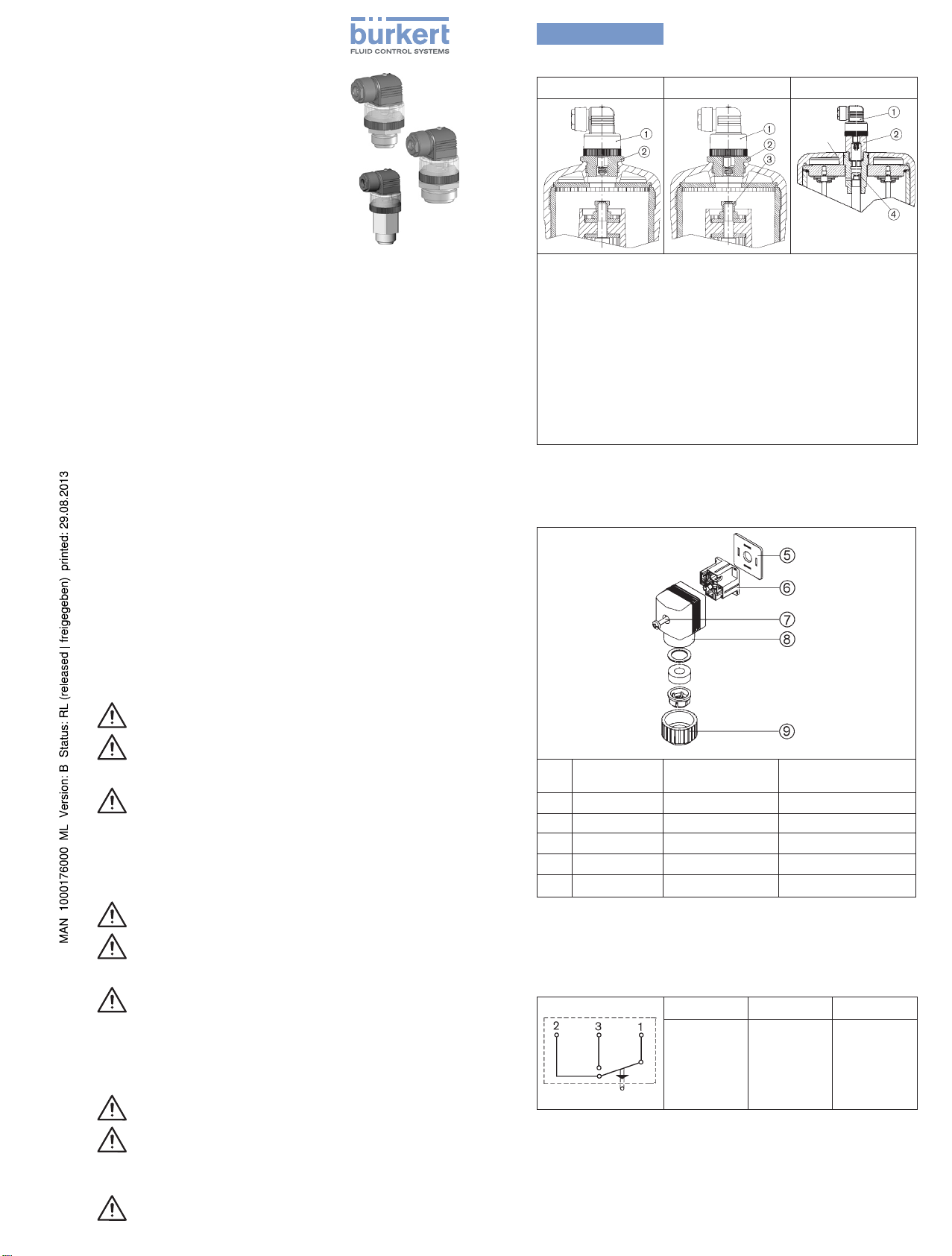
Actuators / Antriebe / Mécanisme de commande
D -50 to/bis/á F -80 G-100, H -125 K-175, L -225
Actuator
Antrieb
commande
Parts required / erforderliche Teile / pièces nécessaires:
① Electrical position repeater with appliance socket
Elektrischer Stellungsrückmelder mit Gerätesteckdose
Dispositif électrique de quittance de position avec
prise de courant sur l‘appareil
② Adapter / Adaptateur
③ Threaded sleeve (only for Types 2030,2031)
Gewindebuchse (nur für Typ 2030, 2031)
Douille filetée (seulement pour type 2030, 2031)
④ Spindle cap / Spindelabdeckkappe / Capuchon de tige
Fig./Bild 1: Actuators / Antriebe / Mécanisme de commande
Electrical Connection / Elektrischer Anschluss / Raccord
électrique
© 2012 Bürkert Werke GmbH
Operating Instructions 1205/01_EU-ml _00809739 / Original DE
SYMBOLS
→
designates a procedure which you must carry out.
Warning of serious or fatal injuries:
DANGER!
In case of imminent danger.
WARNING!
In case of potential danger.
Warning of minor or moderately severe injuries:
CAUTION!
DARSTELLUNGSMITTEL
→
markiert einen Arbeitsschritt den Sie ausführen müssen.
Warnung vor schweren oder tödlichen Verletzungen:
GEFAHR!
Bei unmittelbarer Gefahr.
WARNUNG!
Bei möglicher Gefahr.
Warnung vor leichten oder mittelschweren Verletzungen:
VORSICHT!
SYMBOLES
→
identifie une opération que vous devez effectuer.
Mise en garde contre les blessures graves ou mortelles :
DANGER!
En cas de danger imminent
AVERTISSEMENT!
En cas de danger possible.
Mise en garde contre les blessures légères ou moyennement
graves :
ATTENTION!
Pos. Designation
of parts
⑤
Flat seal Flachdichtung
⑥
Contact insert Kontakteinsatz Insert de contact
⑦
Cap screw Zylinderschraube Vis à tête cylindrique
⑧
Cap Kappe Capuchon
⑨
Coupling nut Überwurfmutter Ècrou d'accouplement
Teilebezeichnung Désignation des
pièces
Joint plat
Fig./Bild 2: Electrical connection / elekrischer Anschluss /
raccord électrique
Electrical connection scheme / elektrisches
Anschlussschema / schéma électrique
Assignment Belegung Affectation
1. Input
2. Break
contact
3. Make
contact
1. Eingang
2. Öffner
3. Schließer
1. Entrée
2. Contact
de repos
3. Contact
de travail
Fig./Bild 3: Electrical connection scheme / elektrisches
Anschlussschema / schéma électrique
Page 2
english
1. OPERATING INSTRUCTIONS
The operating instructions contain important information.
• Read the instructions carefully and follow the safety instructions
in particular.
• Keep the instructions in a location where they are available to
every user.
• The liability and warranty for Type 1060 are void if the operating
instructions are not followed.
Type 1060
→ Screw transparent hood off the actuator cover.
→ Unscrew position indicator using Allen key (size 8).
→ Type 2030, 2031: Screw threaded bushing ③(seeFig.1)
onto the actuator spindle (size 14).
→ Then interrupt the control air supply.
→ Screw adapter ② instead of the transparent hood onto the
actuator (see Fig. 1).
→ Screw electr. position feedback ① into adapter ② (see Fig. 1).
2. INTENDED USE
Operate the electrical position feedback type 1060 only when in
perfect condition and pay attention to correct storage, transportation,
installation and operation.
3. BASIC SAFETY INSTRUCTIONS
These safety instructions do not make allowance for any contingencies and events which may arise during installation, operation
and maintenance.
WARNING!
Danger – high pressure!
• Before loosening lines or valves, turn off the pressure and vent
the lines.
To prevent injury, ensure the following:
• Do not use type 1060 in potentially explosive areas.
• Do not make any internal or external changes to type 1060.
Secure device from unintentional actuation.
• Only trained technicians may perform installation and maintenance work.
• After an interruption in the power supply, ensure that the process is restarted in a controlled manner.
• Observe the general regulations of technology.
4. INSTALLATION AND START-UP
4.1. Actuator D-50 to F-80
Tasks before Installation
DANGER!
Risk of injury from high pressure!
• Before converting the devices, switch off the pressure and
vent the lines.
→ Interrupt the control air supply and flow of medium.
→ Screw transparent hood off the actuator cover.
→ Unscrew position indicator using Allen key (size 5).
→ Screw adapter ② instead of the transparent hood onto the
actuator (see Fig. 1).
→ Screw electr. position feedback ① into adapter ② (see Fig. 1).
4.2. Actuator G-100, H-125
Tasks before Installation
DANGER!
Risk of injury from high pressure!
• Before converting the devices, switch off the pressure and
vent the lines.
→ Interrupt the flow of medium.
→ Empty the valve housing.
→ Move actuator into upper piston position.
DANGER!
Control function B and I:
Risk of injury when unscrewing the transparent hood!
Transparent hood must not be under pressure when unscrewed.
• Before unscrewing the transparent hood, pressurize only
lower piston chamber with compressed air via lower control
air connection.
4.3. Actuator K-175, L-225
Tasks before Installation
WARNING!
Risk of injury and malfunction caused by parts jumping out
or slipping!
The actuators contain pretensioned springs which can jump out
or slip if not opened properly.
• The actuators K-175 / L-225 may be opened by the manufacturer or responsible sales office only.
DANGER!
Risk of injury from high pressure!
• Before converting the devices, switch off the pressure and
vent the lines.
→ Interrupt the flow of medium.
→ Empty the valve housing.
→ Move actuator into upper piston position.
DANGER!
Control function A and I:
Risk of injury when unscrewing the transparent hood!
Transparent hood must not be under pressure when unscrewed.
• Before unscrewing the transparent hood, pressurize only
lower piston chamber with compressed air via lower control
air connection.
→ Screw transparent hood off the actuator cover.
→ Unscrew position indicator (yellow screw cap) by hand.
→ Screw spindle cover cap④ (see Fig. 1) instead of the position
indicator onto the end of the spindle (size 14).
→ Then interrupt the control air supply.
4.4. Installation and start-up
→ Screw adapter ② instead of the transparent hood onto the
actuator (see Fig. 1).
→ Screw electr. position feedback ① into adapter ② (see Fig. 1).
5. ELECTRICAL CONNECTION (for all actuators)
→ Loosen cylinder head screw ⑦ (see Fig. 2) on device socket
and remove socket.
NOTE!
Bent plug tabs will prevent the contact insert from being
reinstalled properly, thereby resulting in functional failure!
• Carefully remove the contact insert and make certain the plug
tabs are not bent.
→ Loosen screw in the contact insert ⑥,takeoutcontactinsert
(seeFig.2).
→ Feed cable through union nut ⑨.
→ Connect according to the circuit (see Fig. 3).
→ Max. connected loads: 5 A at 250 V AC
0.25 A at 250 V DC.
→ Insert contact insert ⑥ into cap ⑧ and screw on (see Fig. 2).
→ Screw on device socket with cylinder head screw ⑦, ensuring
that the flat seal is securely positioned
⑤(seeFig.2).
→ Check the valve for function and leaks.
Page 3

deutsch
I. DIE BEDIENUNGSANLEITUNG
Die Bedienungsanleitung enthält wichtige Informationen.
• Die Anleitung sorgfältig lesen und besonders die Hinweise zur
Sicherheit beachten.
• Die Anleitung so aufbewahren, dass sie jedem Benutzer zur
Verfügung steht.
• Die Haftung und Gewährleistung für Typ 1060 entfällt, wenn die
Anweisungen der Bedienungsanleitung nicht beachtet werden.
II. BESTIMMUNGSGEMÄSSER GEBRAUCH
Den elektrischen Stellungsrückmelder Typ 1060 nur in einwandfreiem
Zustand betreiben und auf sachgerechte Lagerung, Transport,
Installation und Bedienung achten.
III. GRUNDLEGENDE SICHERHEITSHINWEISE
Diese Sicherheitshinweise berücksichtigen keine Zufälligkeiten und
Ereignisse, die bei Montage, Betrieb und Wartung auftreten können.
WARNUNG!
Gefahr durch hohen Druck!
• Vor dem Lösen von Leitungen oder Ventilen den Druck abschalten und Leitungen entleeren.
Zum Schutz vor Verletzungen beachten:
• Typ 1060 nicht in explosionsgefährdeten Bereichen einsetzen.
• An Typ 1060 keine inneren oder äußeren Veränderungen
vornehmen. Gerät vor unbeabsichtigter Betätigung sichern.
• Nur geschultes Fachpersonal darf Installations- und
Instandhaltungsarbeiten ausführen.
• Nach Unterbrechung der elektrischen Versorgung für einen
kontrollierten Wiederanlauf des Prozesses sorgen.
• Die allgemeinen Regeln der Technik einhalten.
IV. EINBAU UND INBETRIEBNAHME
IV.I. Antrieb D-50 bis F-80
Arbeiten vor dem Einbau
GEFAHR!
Verletzungsgefahr durch hohen Druck!
• Vor Umbau der Geräte Druck abschalten, Leitungen entlüften.
→ Zufuhr der Steuerluft und des Mediumstromes unterbrechen.
→ Klarsichthaube vom Antriebsdeckel abschrauben.
→ Stellungsanzeige mit Innensechskantschlüssel (SW5)
abschrauben.
→ Adapter ② anstelle der Klarsichthaube auf Antrieb schrauben
(s. Bild 1).
→ Elektr. Stellungsrückmelder ① in Adapter ② schrauben (s. Bild 1).
IV.II. Antrieb G-100, H-125
Arbeiten vor dem Einbau
GEFAHR!
Verletzungsgefahr durch hohen Druck!
• Vor Umbau der Geräte Druck abschalten, Leitungen entlüften.
→ Zufuhr des Mediumstromes unterbrechen.
→ Ventilgehäuse entleeren.
→ Antrieb in obere Kolbenposition bringen.
GEFAHR!
Steuerfunktion B und I:
Verletzungsgefahr beim Abschrauben der Klarsichthaube!
Klarsichthaube darf beim Abschrauben nicht unter Druck stehen.
• Vor Abschrauben der Klarsichthaube nur unteren Kolbenraum
über unteren Steuerluftanschluss mit Druckluft beaufschlagen.
Typ 1060
→ Typ 2030, 2031: Gewindebuchse ③(s.Bild1) auf die
Antriebsspindel schrauben (SW14).
→ Danach Zufuhr der Steuerluft unterbrechen.
→ Adapter ② anstelle der Klarsichthaube auf Antrieb schrauben
(s. Bild 1).
→ Elektr. Stellungsrückmelder ① in Adapter ② schrauben (s. Bild 1).
IV.III. Antrieb K-175, L-225
Arbeiten vor dem Einbau
WARNUNG!
Verletzungsgefahr und Funktionsausfall durch herausspringende oder verrutschte Teile!
Die Antriebe enthalten vorgespannte Federn, die bei unsachgemäßer Öffnung herausspringen oder verrutschen können.
• Die Antriebe K-175 / L-225 dürfen nur vom Hersteller oder von
der zuständigen Vertriebsniederlassung geöffnet werden.
GEFAHR!
Verletzungsgefahr durch hohen Druck!
• Vor Umbau der Geräte Druck abschalten, Leitungen entlüften.
→ Zufuhr des Mediumstromes unterbrechen.
→ Ventilgehäuse entleeren.
→ Antrieb in obere Kolbenposition bringen.
GEFAHR!
Steuerfunktion A und I:
Verletzungsgefahr beim Abschrauben der Klarsichthaube!
Klarsichthaube darf beim Abschrauben nicht unter Druck stehen.
• Vor Abschrauben der Klarsichthaube nur unteren Kolbenraum
über unteren Steuerluftanschluss mit Druckluft beaufschlagen.
→ Klarsichthaube vom Antriebsdeckel abschrauben.
→ Stellungsanzeige (gelbe Schraubkappe) von Hand
abschrauben.
→ Spindelabdeckkappe④ (s. Bild 1) anstelle der Stellungsan-
zeige auf Spindelende aufschrauben (SW14).
→ Danach Zufuhr der Steuerluft unterbrechen.
IV.IV. Einbau und Inbetriebnahme
→ Adapter ② anstelle der Klarsichthaube auf Antrieb schrauben
(s. Bild 1).
→ Elektr. Stellungsrückmelder ① in Adapter ② schrauben (s. Bild 1).
V. ELEKTRISCHER ANSCHLUSS (für alle Antriebe)
→ Zylinderschraube ⑦ (s. Bild 2) an Gerätesteckdose lösen,
diese abnehmen.
HINWEIS!
Funktionsausfall durch verbogene Steckerfahnen, die den
Wiedereinbau des Kontakteinsatzes verhindern!
• Den Kontakteinsatz vorsichtig herausnehmen und darauf
achten, dass die Steckerfahnen nicht verbogen werden.
→ Schraube im Kontakteinsatz ⑥ lösen, Kontakteinsatz heraus-
nehmen (s. Bild 2).
→ Kabel durch Überwurfmutter ⑨ führen.
→ Anschluss entsprechend der Schaltung vornehmen (s. Bild 3).
→ Max. Anschlusswerte: 5 A bei 250 V AC
0,25 A bei 250 V DC.
→ Kontakteinsatz ⑥ in Kappe ⑧ einsetzen und anschrauben
(s. Bild 2).
→ Gerätesteckdose mit Zylinderschraube ⑦ anschrauben, dabei
auf sicheren Sitz der Flachdichtung ⑤ achten (s. Bild 2).
→ Ventil auf Funktion und Dichtheit prüfen.
→ Klarsichthaube vom Antriebsdeckel abschrauben.
→ Stellungsanzeige mit Innensechskantschlüssel (SW8)
abschrauben.
Page 4

français
1. INSTRUCTIONS DE SERVICE
Les instructions de service contiennent des informations
importantes.
• Lire attentivement les instructions et tenir particulièrement
compte des consignes de sécurité.
• Conserver les instructions afin qu'elles soient accessibles à tous
les utilisateurs.
• La responsabilité et la garantie légale concernant le type 1060
sont exclues en cas de non-respect des instructions de service.
2. UTILISATION CONFORME
Utiliser l’indicateur de position électrique du type 1060 uniquement
en parfait état et veiller à ce que le stockage, le transport, l’installation
et l’utilisation s’effectuent dans les règles.
Type 1060
→ Dévisser le capot transparent du couvercle d’entraînement.
→ Dévisser l’indicateur de position avec une clé à six pans creux
(clé de 8).
→ Types 2030, 2031 : visser la douille filetée ③(voirFig.1) sur
la broche d’entraînement (clé de 14).
→ Ensuite, interrompre l’arrivée de l’air de commande.
→ Visser l’adaptateur ② sur l’entraînement à la place du capot
transparent (voir Fig. 1).
→ Visser l’indicateur de position électrique ① dans l’adaptateur ②
(voir Fig. 1).
4.3. Entraînements K-175, L-225
Interventions avant le montage
AVERTISSEMENT !
3. CONSIGNES DE SÉCURITÉ FONDAMENTALES
Ces consignes de sécurité ne tiennent pas compte des hasards et
des événements pouvant survenir lors du montage, de l’exploitation
et de l’entretien.
AVERTISSEMENT !
Danger dû à la haute pression !
• Avant de desserrer les conduites et les vannes, couper la
pression et purger l'air des conduites.
Pour prévenir les blessures, veuillez tenir compte de ce qui suit :
• Ne pas utiliser le type 1060 dans les zones présentant des
risques d'explosion.
• Ne pas apporter de modifications internes ou externes à
l'appareil du type 1060. Protéger l'appareil contre toute mise en
marche involontaire.
• Seul du personnel qualifié peut effectuer l'installation et la
maintenance.
• Garantir un redémarrage contrôlé du process après la coupure
de l'alimentation électrique.
• Respecter les règles générales de la technique.
4. MONTAGE ET MISE EN SERVICE
4.1. Entraînements D-50 à F-80
Interventions avant le montage
DANGER !
Risque de blessures dû à la haute pression !
• Avant de procéder à la transformation des appareils, couper la
pression et purger l'air des conduites.
→ Interrompre l’arrivée d’air de commande et du flux de fluide.
→ Dévisser le capot transparent du couvercle d’entraînement.
→ Dévisser l’indicateur de position avec une clé à six pans creux
(clé de 5).
→ Visser l’adaptateur ② sur l’entraînement à la place du capot
transparent (voir Fig. 1).
→ Visser l’indicateur de position électrique ① dans l’adaptateur ②
(voir Fig. 1).
4.2. Entraînement G-100, H-125
Interventions avant le montage
DANGER !
Risque de blessures dû à la haute pression !
• Avant de procéder à la transformation des appareils, couper la
pression et purger l'air des conduites.
→ Interrompre l’arrivée du flux de fluide.
→ Effectuer une purge d’air du corps de vanne.
→ Amener l’entraînement dans la position de piston supérieure.
DANGER !
Fonctions de commande B et I :
risque de blessures lors du dévissage du capot transparent !
Le capot transparent ne doit pas être sous pression lors du
dévissage.
• Avant de dévisser le capot transparent, appliquer de l'air
comprimé uniquement à la chambre de piston inférieure
par le raccord d'air de commande inférieur.
Risque de blessures et de pannes dû à la sortie ou au
glissement des pièces !
Les entraînements contiennent des ressorts précontraints susceptibles de sortir ou de glisser en cas d'ouverture non conforme.
• Les entraînements K-175 / L-225 doivent être ouverts uniquement par le fabricant ou par la filiale de distribution compétente.
DANGER !
Risque de blessures dû à la haute pression !
• Avant de procéder à la transformation des appareils, couper la
pression et purger l'air des conduites.
→ Interrompre l’arrivée du flux de fluide.
→ Effectuer une purge d’air du corps de vanne.
→ Amener l’entraînement dans la position de piston supérieure.
DANGER !
Fonctions de commande A et I :
risque de blessures lors du dévissage du capot transparent !
Le capot transparent ne doit pas être sous pression lors du
dévissage.
• Avant de dévisser le capot transparent, appliquer de l'air
comprimé uniquement à la chambre de piston inférieure
par le raccord d'air de commande inférieur.
→ Dévisser le capot transparent du couvercle d’entraînement.
→ Dévisser l’indicateur de position (capuchon fileté jaune) à la main.
→ Visser le capuchon de protection de broche④ (voir Fig. 1) sur
l’extrémité de la broche à la place de l’indicateur de position
(clé de 14).
→ Ensuite, interrompre l’arrivée de l’air de commande.
4.4. Montage et mise en service
→ Visser l’adaptateur ② sur l’entraînement à la place du capot
transparent (voir Fig. 1).
→ Visser l’indicateur de position électrique ① dans l’adaptateur ②
(voir Fig. 1).
5. RACCORDEMENT ÉLECTRIQUE (pour tous les
entraînements)
→ Desserrer la vis à tête cylindrique ⑦ (voir Fig. 2) sur la prise de
l’appareil, retirer celle-ci.
REMARQUE !
Panne due à des barrettes de raccordement tordues,
empêchant le remontage de l'insert de contact !
• Retirer l'insert de contact avec précaution et veiller à ne pas
tordre les barrettes de raccordement.
→ Desserrer la vis dans l’insert de contact ⑥,retirercelui-ci(voir
Fig.2).
→ Faire passer le câble à travers l’écrou-raccord ⑨.
→ Effectuer le raccordement conformément au schéma électrique
(voir Fig. 3).
→ Valeurs de raccordement maxi : 5 A à 250 V AC
0,25 A à 250 V DC.
→ Mettre l’insert de contact ⑥ en place dans le capuchon ⑧ et
le visser (voir Fig. 2).
→ Visser la prise de l’appareil avec la vis à tête cylindrique ⑦ en
veillant à la bonne assise du joint plat
⑤(voirFig.2).
→ Contrôler le fonctionnement et l’étanchéité de la vanne.
 Loading...