

Page 1
PTB 03 ATEX 1030 X
Device with II 2G/D Ex approval
Geräte mit II 2G/D Ex Zulassung
Appareils avec mode de protection II 2G/D Ex
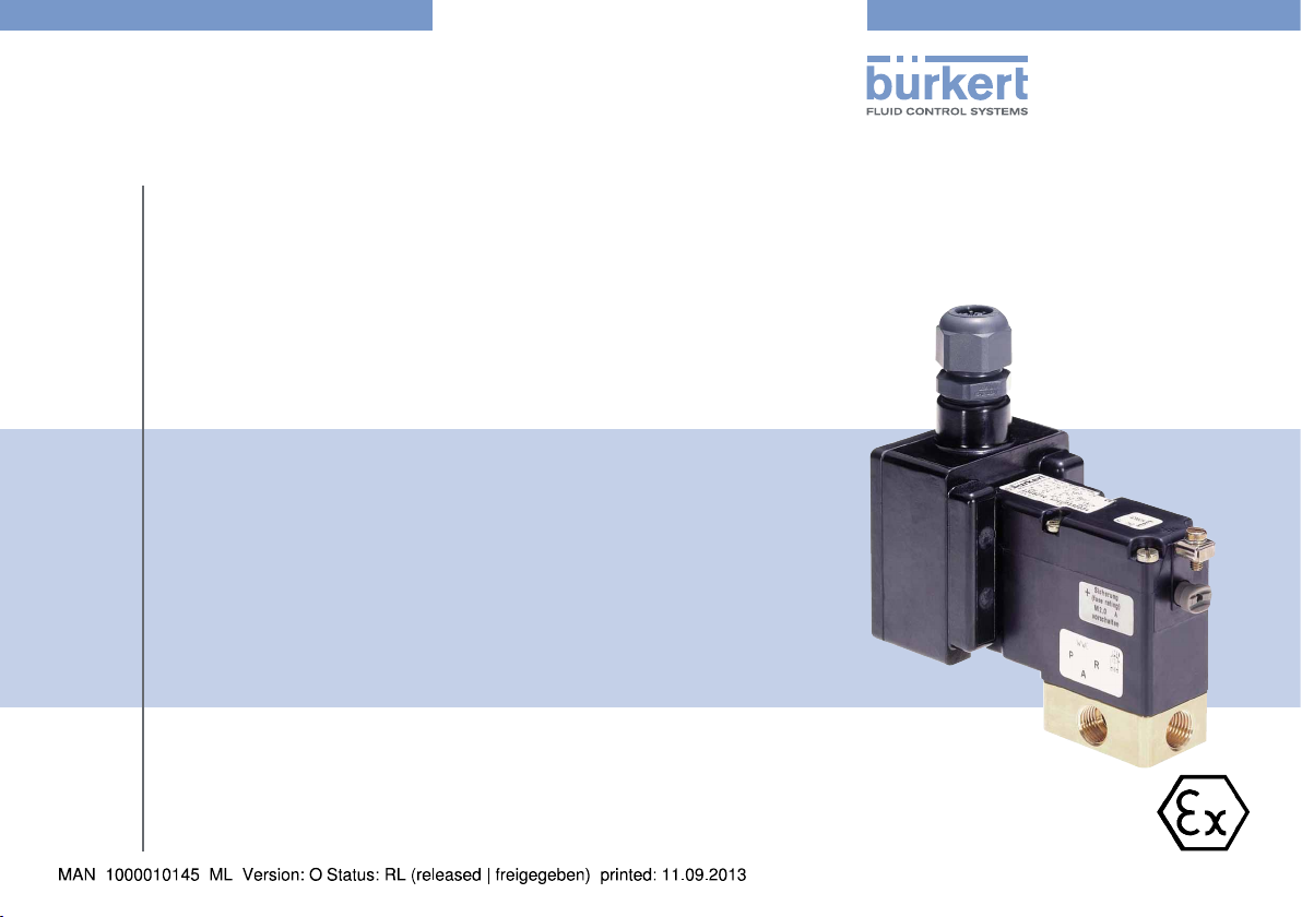
Example/Beispiel/Exemple
Coil type 0780 with valve body type 0330
Spule Typ 0780 mit Gehäuse Typ 0330
Bobine type 0780 avec le corps type 0330
Operating Instructions
Bedienungsanleitung
Manuel d‘utilisation
Page 2
We reserve the right to make technical changes without notice.
Technische Änderungen vorbehalten.
Sous resérve de modification techniques.
© 2008 - 2013 Bürkert Werke GmbH
Operating Instructions 1309/12_EU-ML_00804717 / Original DE
Page 3
PTB 03 ATEX 1030 X
Device with II 2G/D Ex certification
1. THE OPERATING INSTRUCTIONS .........................................................4
1.1. Symbols ..............................................................................................4
2. INTENDED USE ................................................................................................5
2.1. Restrictions ........................................................................................5
2.2. Ex-Approval ....................................................................................... 5
2.3. Special instructions in explosion-risk areas ............................... 6
3. GENERAL SAFETY INSTRUCTIONS .....................................................6
4. GENERAL INFORMATION ...........................................................................7
4.1. Contact Address ..............................................................................7
4.2. Warranty .............................................................................................7
4.3. Information on the Internet ............................................................. 7
5. APPLICATION CONDITIONS .....................................................................8
5.1. Special conditions ...........................................................................8
6. TECHNICAL DATA / SAFE OPERATION ..............................................9
6.1. Conformity .........................................................................................9
6.2. Standards ........................................................................................... 9
6.3. Operating Conditions ...................................................................... 9
6.4. General Technical Data ................................................................11
7.4. Disassembly ....................................................................................14
8. START-UP .........................................................................................................14
8.1. Safety Instructions .........................................................................14
9. MAINTENANCE, REPAIR, TROUBLESHOOTING .........................15
9.1. Maintenance and repair ................................................................15
9.2. Troubleshooting ..............................................................................15
10. ACCESSORIES ...........................................................................................15
10.1. Spare parts ....................................................................................15
11. TRANSPORT, STORAGE, DISPOSAL .............................................. 16
7. ASSEMBLY AND DISASSEMBLY .........................................................12
7.1. Safety Instructions .........................................................................12
7.2. Installation of valve .........................................................................13
7.3. Electrical connection .....................................................................13
english
3
Page 4
PTB 03 ATEX 1030 X
The Operating Instructions
1. THE OPERATING INSTRUCTIONS
The operating instructions describe the entire life cycle of the device.
Keep these instructions in a location which is easily accessible to
every user and make these instructions available to every new owner
of the device.
The operating instructions contain important safety
information!
Failure to observe these instructions may result in hazardous situations. The operating instructions must be read and understood.
• Carefully read the operating instructions before using the device.
• In particular observe the chapter entitled “Intended Use”, and
“General Safety Instructions” as well as the chapter entitled
„Application Conditions“.
1.1. Symbols
In the instructions, the following symbols are used to identify important
information:
DANGER!
Warns of an immediate danger!
• Failure to observe the warning may result in a fatal or serious injury.
WARNING!
Warns of a potentially dangerous situation!
• Failure to observe the warning may result in serious injuries or
death.
CAUTION!
Warns of a possible danger!
• Failure to observe the warning may result in moderately serious
or minor injuries.
NOTE!
Warns of damage to property!
Important tips and recommendations.
Refers to information in these operating instructions or in
other documentation.
→ designates a procedure which you must carry out.
4
english
Page 5
PTB 03 ATEX 1030 X
Intended Use
2. INTENDED USE
Incorrect use may be a hazard to people, nearby equipment
and the environment.
• The device serves exclusively as a solenoid valve for the media
stated in the data sheet and for use in Explosion Group IIC,
Category 2G and Temperature Class T4 or T5 (see data on the
- Ex approval plate).
• The device may be used only in category 2D with the temperatures
T135 °C and/or 100 °C as well as for the designated application
cases specified in chapter “5. Application Conditions” and in conjunction with third-party devices and components recommended
and authorized by Bürkert.
• The applied ignition protection types are the pressure-resistant
casing “d” with increased safety “e”. The safety fuse incorporated in version PD29 is executed in ignition protection type
encapsulation “m”. The proximity switch, which can be optionally
incorporated in all versions, is executed in ignition protection
type intrinsic safety “ia”.
The composition of the ignition protection code follows the ignition protection types of the components used in each case.
• Correct transportation, correct storage and installation and careful
use and maintenance are essential for reliable and problem-free
operation.
Any other use is considered improper use. Bürkert is not liable
for any resulting damage. The user alone bears the risk.
• Use the device only as intended.
2.1. Restrictions
If exporting the device, observe any existing restrictions.
2.2. Ex-Approval
The Ex approval is only valid if you use the modules and components
authorised by Bürkets in such a way as described in this operating
manual.
The coil type 0770/0780 may only be used in combination with additional components that have been approved by Bürkert. Otherwise, the
Ex approval will expire!
If you make any unauthorized changes to the device, the modules or
the components, the Ex approval will also expire.
The EC Qualification Test Certificate PTB 03 ATEX 1030 X and the
IECEx Certificate of Conformity IECEx PTB 05.0026X has been
drawn up by the:
PTB (Physikalisch Technische Bundesanstalt)
Bundesallee 100
38116 Braunschweig
who also audited the manufacture (CE0102).
The EC type approval test certificate can be found on the Internet at:
www.burkert.com
english
5
Page 6
PTB 03 ATEX 1030 X
General Safety Instructions
2.3. Special instructions in explosion-risk
areas
WARNING!
Danger caused by electrostatic charge!
If there is a sudden discharge from electrostatically charged devices
or persons, there is a danger of explosion in the explosion-risk area.
• Take appropriate measures to prevent electrostatic charges in
explosion-risk areas.
• Clean the device surface by gently wiping it with a damp or
antistatic cloth only.
Additional special conditions can be found under “5.1” of
these operating instructions.
3. GENERAL SAFETY INSTRUCTIONS
These safety instructions do not take into account
• any contingencies or events which may occur during the installation,
operation and maintenance of the devices.
• local safety regulations, the observance of which is the responsibility
of the operator, also with respect to the installation personnel.
Danger of explosion!
• The device is a sealed system. It must not be opened
Danger of electrostatic charge!
Acute risk of injury from hazardous structure-borne voltage!
Risk of damage to the device due to short circuit!
• Before starting work, switch off the power supply and secure to
prevent it being switched on again!
• Observe the applicable accident prevention and safety regulations for electrical devices!
Danger - high pressure!
• There is a serious risk of injury when reaching into the
equipment.
• Before loosening the lines and valves, turn off the pressure and
vent the lines.
• Observe the currently valid accident prevention and safety
regulations!
6
english
Page 7
PTB 03 ATEX 1030 X
General Information
4. GENERAL INFORMATION
Danger of explosion caused by electrostatic charge!
If there is a sudden discharge from electrostatically charged
devices or persons, there is a danger of explosion in the Ex area.
• Take appropriate measures to prevent electrostatic charges in
the Ex area.
• Clean the device surface by gently wiping it with a damp or
antistatic cloth.
General hazardous situations.
To prevent injury, ensure that:
• That the system cannot be activated unintentionally.
• That no unauthorized changes are performed on the system.
• Only expert and instructed personnel with appropriate tools
carry out any work on the system.
• The device may be operated only when in perfect condition and
in consideration of the operating instructions.
• The general rules of technology apply to application planning
and operation.
4.1. Contact Address
Germany
Bürkert Fluid Control Systems
Sales Center
Chr.-Bürkert-Str. 13-17
D-74653 Ingelfingen
Tel. + 49 (0) 7940 - 10 91 111
Fax + 49 (0) 7940 - 10 91 448
E-mail: info@de.buerkert.com
International
Contact addresses can be found on the final pages of the printed
operating instructions.
And also on the Internet under: www.burkert.com
4.2. Warranty
The warranty is only valid if the device is used as intended in accordance
with the specified application conditions.
4.3. Information on the Internet
The operating manual and the data sheets can be found on the Internet
under: www.burkert.com
english
7
Page 8
5. APPLICATION CONDITIONS
5.1. Special conditions
5.1.1. Short-circuit protection
Each electromagnet shall be provided on the line with a short-circuit
protection in the form of a fuse designed to meet the magnet starting
current (max. 3 x I
motor overload trip instantaneous short-circuit and thermal release
(Adjustment to match the pull-in current).
• At very low pull-in currents of the solenoid the fuse with the lowest
current value is adequate according to the stated IEC standard.
This fuse may be mounted in the associated supply unit or must
be connected in series separately.
• The rated voltage of the fuse must be equal to or larger than the
quoted nominal voltage of the magnet.
• The switch-off capability of the fuse cartridge must be equal to or
greater than the maximum theoretical short-circuit current at the
installation location (normally 1500 A).
• In the case of versions PD30 of the solenoid, short-circuit protection must be assured by the operator.
• In the case of version PD29 of the solenoid, the fuse is installed in
the terminal box of the device.
More detailed descriptions are to be found in the section
“6. Technical data / Safe operation”.
in accordance with IEC 60127-2-1) or a
rating
PTB 03 ATEX 1030 X
Application Conditions
Fuse ... A
5.1.2. Operation with associated valve body
The solenoid coils Type 77. / 78. may only be operated with a valve
body satisfying the following requirements.
For the valve body, the following materials may be used:
• metal (brass, aluminium, stainless steel) or
• plastics (e,g, polyamide PA 6 GV ...)
5.1.3. Manual operation / approximity switch
The solenoid armature can be manually operated via the push
button. The push button may be locked by depressing and turning
by 90°.
As an alternative to manual operation, the solenoid can be equipped
with a proximity switch. The internal code for this version is CF 15.
8
english
Page 9
PTB 03 ATEX 1030 X
Technical data / Safe operation
5.1.4. Model with a terminal box
DANGER!
Risk of explosion!
• Only permanently laid cables and wiring may be inserted.
• The operator must provide suitable stress relief.
• Wires with an outside diameter of 6 to 13 mm may be used.
Observe the maximum thermal loading of the cables or wires to
be inserted.
• The inserted break-off seal must be matched to the diameter of
the cable or wire.
• The rated cross-section of the cable or wire strands must be at
least 0.75 mm² and may not exceed 2.5 mm².
• The screws for fixing the cover of the terminal box must be tightened with a torque of 1 Nm (± 5 %).
The solenoid coils may also be executed with a terminal box, with
or without fuse/contactor (to separate Design Type Inspection Certificate) as desired.
For protection against inadvertent opening of the cover, the latter
bears the marking:
Open only when the voltage is switched off!
6. TECHNICAL DATA / SAFE
OPERATION
6.1. Conformity
The coil type 0770/0780 is compliant with the EC Directives according
to the EC Declaration of Conformity.
6.2. Standards
Refer to the EC type approval test certificate and/or the EC Declaration
of conformity for the applicable standards verifying conformity with the
EC directives.
6.3. Operating Conditions
DANGER!
Risk of explosion by excedance technical data!
Exceeding the technical data indicated on the type label increases
the explosion risk!
• Never exceed the technical data indicated on the type label!
6.3.1. Maximum permissible ambient
temperature range
Please observe the maximum permissible ambient temperature range
given under Operating conditions of the coils for each type!
Version Maximum permissible ambient temperature
range
07xx -30 °C ... +55 °C
english
9
Page 10
PTB 03 ATEX 1030 X
Technical data / Safe operation
6.3.2. Type of protection
IP65 to EN 60529 (DIN VDE 0470 Part 1)
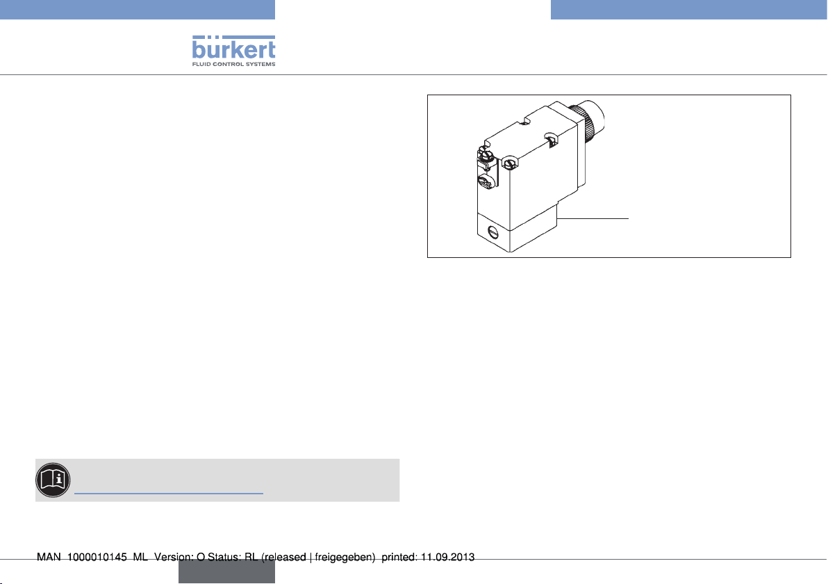
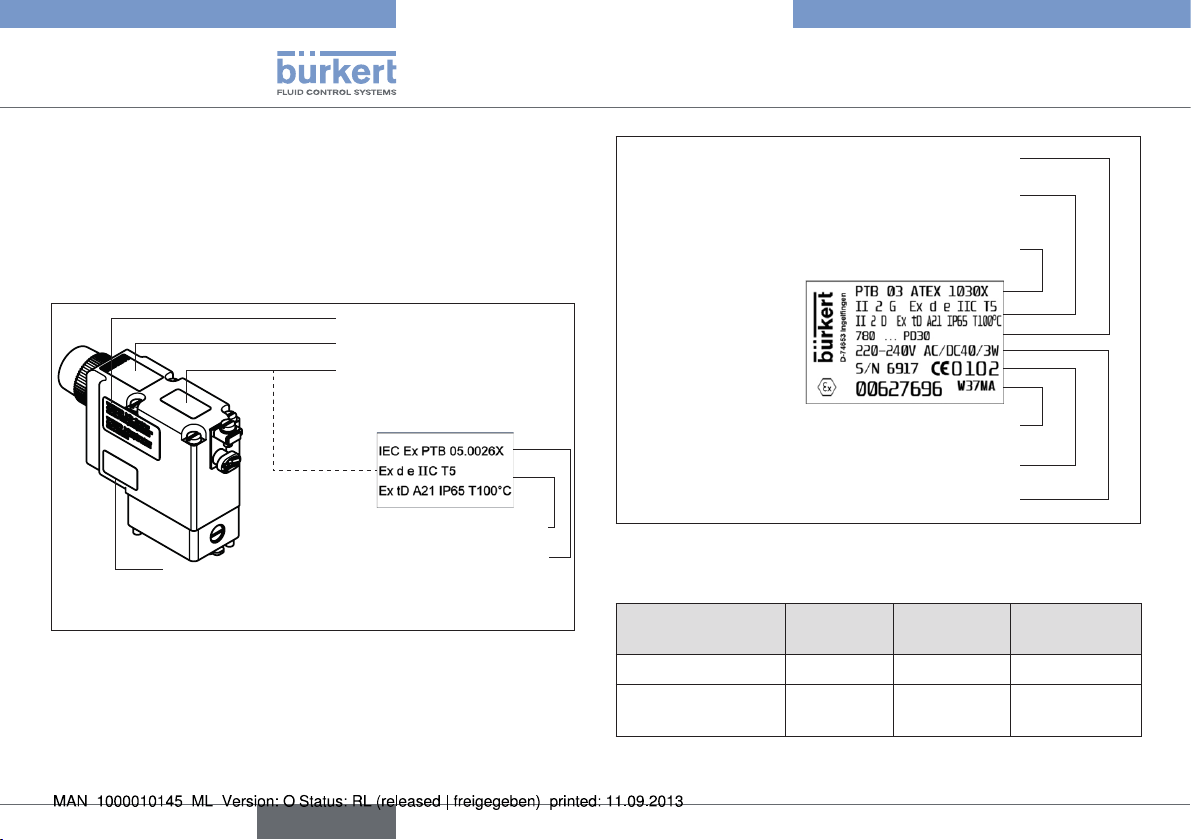
6.3.3. Location and description of the type
label
Warning notices
Type label coil
Type label IEC Ex
Protection class - Temperature class
Fuse
...A
IEC EX Approval number
Fig. 1: Location of the type label
Type and design
Protection class, Temperature class
PTB approval number
Id. number of the coil, Date of manufacture
Serial number of the coil, Inspection body
Voltage (± 10 %), Current type, Power consumption
Fig. 2: Description of the type label
6.3.4. Dimensions
Connection type Length
(mm)
Width
(mm)
Height
(mm)
Molded-in cable 96 32 56
Terminal box with/
123 60 113
without safety fuse
10
english
Page 11
PTB 03 ATEX 1030 X
Technical data / Safe operation
6.3.5. Type of explosion protection
The composition of the explosion protection code follows the explosion
protection types of the components used in each case:
Solenoid with or without
terminal box
Solenoid with terminal
box and fuse
Solenoid without terminal
box with proximity switch
Solenoid with terminal
box, fuse and proximity
switch
II 2 G Ex d e IIC T4 resp. T5
II 2 D Ex tD A21 IP 65 T135 °C resp.
T100 °C
II 2 G Ex d e mb IIC T4
II 2 D Ex tD A21 IP65 T135 °C
II 2 G Ex d e ia IIC T4 resp. T5
II 2 D Ex tD A21 IP65 T135 °C resp.
T100 °C
II 2 G Ex d e ia mb IIC T4
II 2 D Ex tD A21 IP65 T135 °C
6.4. General Technical Data
6.4.1. Electrical Data
Type
Temperature class
Type of current
Rated voltage
Voltage tolerance
Rated current
Pick-up current
Pick-up power
Power consumption for
holding in equilibrium
Max. number of
switching actuations ca
6.4.2. Electrical connection
Version
code
PD30* * Permanently installed rubber sheathed
cable of Type H05 RN-F3G0.75
77. - ... - ... - . 78. - ... - ... - .
T4 T5
Universal Universal
24 ... 240 V 24 ... 240 V
+10 % / -10 % +10 % / -10 %
0,085 ... 0,014 A 0,085 ... 0,014 A
01,66 ... 0,166 A 01,66 ... 0,166 A
40 W 40 W
3 W 3W
20 / min 10 / min
Execution Internal
Code
****JWxx
english
11
Page 12
PTB 03 ATEX 1030 X
Assembly and disassembly
Version
code
** Terminal box with cable bushing M20
Execution Internal
Code
JA02
x 1.5, without fuse
PD30
Terminal box with threaded nipple M20 x
1.5, without fuse
Terminal box with threaded nipple NPT
JA08
JA09
1/2, without fuse
Terminal box with threaded nipple G 1/2,
JA10
without fuse
** Terminal box with cable bushing M20 x
JA01
1.5 and fuse
PD29 ***
Terminal box with threaded nipple M20 x
1.5 and fuse
Terminal box with threaded nipple NPT
JA05
JA06
1/2 and fuse
Terminal box with threaded nipple G 1/2
JA07
and fuse
* The connecting cable of solenoid Type 07xx must be laid permanently
such that it is adequately protected from mechanical damage
** Cable bushing to separate Design Inspection Certificate
*** Fuse protection PD29 to separate type approval test certificate
**** Different cable lengths
7. ASSEMBLY AND DISASSEMBLY
7.1. Safety Instructions
DANGER!
Danger of explosion!
The device is a sealed system. The unit must not be dismantled!
The following safety regulations must be observed:
• The surface of the device may develop an electrostatic charge.
In areas with an explosion hazard, the surface of the units may
only be cleaned with a damp cloth.
• Only permanently laid cables and wiring may be inserted.
• The operator must provide suitable stress relief.
• Wires with an outside diameter of 6 to 13 mm may be used.
Observe the maximum thermal loading of the cables or wires to
be inserted.
• The inserted break-off seal must be matched to the diameter of
the cable or wire.
• The rated cross-section of the cable or wire strands must be at
least 0.75 mm² and may not exceed 2.5 mm².
• The screws for fixing the cover of the terminal box must be tightened with a torque of 1 Nm (±5%).
• The connection nut (clamping nut) of the cable gland on the terminal box must be tightened with a torque of 1.5 Nm (± 5 %).
12
english
Page 13
PTB 03 ATEX 1030 X
Assembly and disassembly
DANGER!
Danger of high voltage!
Acute risk of injury from hazardous structure-borne voltage!
Risk of damage to the device due to short circuit!
• Before starting work, switch off the power supply and secure to
prevent it being switched on again!
• Live terminals in the terminal box can cause electric shock, short
circuit or explosion. Switch off the power supply before opening the terminal box.
• The connecting cables to the electromagnets must be secure,
and be laid so that they are adequately protected from mechanical damage.
• Observe the applicable accident prevention and safety regulations for electrical devices!
WARNING!
Danger - high pressure!
Interventions in the pneumatic system represent an acute risk of
injury.
• First switch off pressure before disconnecting lines and valves.
• Observe the flow direction during installation.
• Observe the applicable accident prevention and safety regulations for pneumatic systems.
7.2. Installation of valve
The solenoid valve can be mounted in any position.
Preferably with solenoid system mounted at the top.
Procedure:
→ Clean pipelines.
→ Connect a dirt trap upstream.
→ Seal pipeline connections with PTFE tape.
→ Screws in pipelines.
Make certain the direction of flow is correct!
→ Check valve for leakage.
7.3. Electrical connection
DANGER!
Risk of injury due to electrical shock!
• Before reaching into the system, switch off the electrical power
supply and secure to prevent reactivation!
• Observe applicable accident prevention and safety regulations
for electrical equipment!
If the protective conductor contact between coil and body is
missing, there is danger of electrical shock!
• Always connect protective conductor.
• Check electrical continuity between coil and body.
english
13
Page 14
Start-up
PTB 03 ATEX 1030 X
The connection cable is encapsulated with the coil and
cannot be removed.
→ Attach the electrical connection.
7.4. Disassembly
DANGER!
Risk of electric shock!
There is a serious risk of injury when reaching into the equipment.
• Only trained electrical engineers may work on the electrical
system.
• Before starting work, always switch off the power supply and
safeguard to prevent re-activation!
• Observe applicable accident prevention and safety regulations
for electrical equipment!
Procedure:
→ Disconnect the power connection.
→ Disconnect the valve body from the pipeline.
NOTE!
Malfunctions as a result of contamination!
• In case of new installation, remove old PTFE tape from the connections. Residues or parts of the tape must not get into the pipeline.
8. START-UP
8.1. Safety Instructions
WARNING!
Danger due to improper operation!
Improper operation may result in injuries as well as damage to the
device and the area around it.
• Before start-up, ensure that the operating personnel are familiar
with and completely understand the contents of the operating
instructions.
• In particular observe the safety instructions and intended use.
• The device may be started by adequately trained personnel only.
Before commissioning, ensure that:
• The device has been correctly installed,
• The connections have been correctly made,
• The device is not damaged,
• All bolts are securely tightened.
14
english
Page 15

PTB 03 ATEX 1030 X
Maintenance, Repair, Troubleshooting
9. MAINTENANCE, REPAIR,
TROUBLESHOOTING
9.1. Maintenance and repair
DANGER!
Danger due to improper maintenance, repair and inspection
work!
• The maintenance and inspection work on the device may be carried
out by authorized technicians only and with the appropriate tools!
• Repairs on the device may only be carried out by the
manufacturer!
• When performing repair or maintenance work on the system, the
valve may not be opened and the protective-conductor connection
may not be disconnected!
9.2. Troubleshooting
In the event of faults, make sure that:
• the device has been installed according to the specifications,
• the connection has been established properly,
• the device is not damaged,
• all screws have been tightened,
• the voltage and pressure have been switched on,
• the pipelines are free.
10. ACCESSORIES
CAUTION!
Risk of injury and / or damage by the use of incorrect parts!
Incorrect accessories and unsuitable parts may cause injuries and
damage the device and the surrounding area.
• Use only original accessories and original spare supplied by
Bürkert.
10.1. Spare parts
For electromagnet models with terminal boxes, fuses of the Type 1058
with approval PTB 01 ATEX 2064 U can be used in Temperature
Class T4.
Fuse
Type 1058
0.063 A 153717
0.080 A 153745
0.100 A 153718
0.125 A 153719
0.160 A 153720
0.200 A 153731
0.315 A 153733
0.400 A 153734
0.500 A 153735
0.630 A 153736
0.800 A 153737
Order
No.
english
15
Page 16

PTB 03 ATEX 1030X
Transport, Storage, Disposal
Fuse
Type 1058
1.000 A 153738
1.250 A 153739
1.600 A 153746
2.000 A 153740
3.150 A 153742
Order
No.
11. TRANSPORT, STORAGE, DISPOSAL
NOTE!
Transport damages!
Inadequately protected equipment may be damaged during
transport.
• During transportation protect the device against wet and dirt in
shock-resistant packaging.
• Avoid exceeding or dropping below the allowable storage
temperature.
Incorrect storage may damage the device.
• Store the device in a dry and dust-free location!
• Storage temperature: -40 … +60 °C.
Damage to the environment caused by device components
contaminated with media.
• Ensure the device and packaging are disposed of in an environmentally sound manner.
• Observe applicable regulations relating to refuse disposal and
the environment.
16
english
Page 17

PTB 03 ATEX 1030 X
Geräte mit II 2G/D Ex Zulassung
1. BEDIENUNGSANLEITUNG ...................................................................... 18
1.1. Darstellungsmittel ...........................................................................18
2. BESTIMMUNGSGEMÄSSE VERWENDUNG ................................... 19
2.1. Beschränkungen ............................................................................19
2.2. Ex-Zulassung ...................................................................................19
2.3. Besondere Hinweise im Ex-Bereich ..........................................20
3. ALLGEMEINE SICHERHEITSHINWEISE...........................................20
4. ALLGEMEINE HINWEISE .......................................................................... 21
4.1. Kontaktadressen .............................................................................21
4.2. Gewährleistung...............................................................................21
4.3. Informationen im Internet ..............................................................21
5. EINSATZBEDINGUNGEN ......................................................................... 22
5.1. Besondere Bedingungen .............................................................22
6. TECHNISCHE DATEN / SICHERER BETRIEB...............................23
6.1. Konformität .......................................................................................23
6.2. Normen .............................................................................................23
6.3. Betriebsbedingungen ....................................................................23
6.4. Allgemeine Technische Daten .....................................................25
7.4. Demontage ......................................................................................28
8. INBETRIEBNAHME ...................................................................................... 28
9. WARTUNG, REPARATUR, FEHLERBEHEBUNG ........................... 29
9.1. Wartung und Reparatur ................................................................29
9.2. Fehlerbehebung ..............................................................................29
10. ERSATZTEILE ............................................................................................... 29
10.1. Zubehör ..........................................................................................29
11. TRANSPORT, LAGERUNG, ENTSORGUNG ................................. 30
7. MONTAGE UND DEMONTAGE .............................................................. 26
7.1. Sicherheitshinweise .......................................................................26
7.2. Installation des Ventils ...................................................................27
7.3. Elektrischer Anschluss ..................................................................27
deutsch
17
Page 18

PTB 03 ATEX 1030 X
Bedienungsanleitung
1. BEDIENUNGSANLEITUNG
Die Bedienungsanleitung beschreibt den gesamten Lebenszyklus
des Geräts. Bewahren Sie diese Anleitung so auf, dass sie für jeden
Benutzer gut zugänglich ist und jedem neuen Eigentümer des Geräts
wieder zur Verfügung steht.
Die Bedienungsanleitung enthält wichtige Informationen zur
Sicherheit!
Das Nichtbeachten dieser Hinweise kann zu gefährlichen Situationen
führen. Die Anleitung muss gelesen und verstanden werden.
• Lesen Sie die Bedienungsanleitung vor dem Einsatz des Geräts
sorgfältig durch.
• Beachten Sie vor allem die Kapitel „Bestimmungsgemäße
Verwendung“, und „Allgemeine Sicherheitshinweise“ sowie das
Kapitel „Einsatzbedingungen“.
1.1. Darstellungsmittel
Für die Kennzeichnung wichtiger Informationen werden in der Anleitung
folgende Darstellungsmittel verwendet:
GEFAHR!
Warnt vor einer unmittelbaren Gefahr!
• Bei Nichtbeachtung sind Tod oder schwere Verletzungen die Folge.
WARNUNG!
Warnt vor einer möglicherweise gefährlichen Situation!
• Bei Nichtbeachtung drohen schwere Verletzungen oder Tod.
VORSICHT!
Warnt vor einer möglichen Gefährdung!
• Nichtbeachtung kann mittelschwere oder leichte Verletzungen
zur Folge haben.
HINWEIS!
Warnt vor Sachschäden!
• Bei Nichtbeachtung kann Gerät oder Anlage beschädigt werden.
Bezeichnet wichtige Zusatzinformationen, Tipps und
Empfehlungen.
Verweist auf Informationen in dieser Bedienungsanleitung
oder in anderen Dokumentationen.
18
→ markiert einen Arbeitsschritt, den Sie ausführen müssen.
deutsch
Page 19

PTB 03 ATEX 1030 X
Bestimmungsgemäße Verwendung
2. BESTIMMUNGSGEMÄSSE
VERWENDUNG
Bei nicht bestimmungsgemäßem Einsatz können Gefahren für
Personen, Anlagen in der Umgebung und die Umwelt entstehen.
• Das Gerät dient ausschließlich als Magnetventil für die Iaut Datenblatt zulässigen Medien und für den Einsatz in Explosionsgruppe
IIC, Kategorie 2G und Temperaturklasse T4 oder T5 (siehe Angaben auf dem
• Das Gerät darf nur für den Einsatz in Kategorie 2D mit den Temperaturen T135 °C bzw. 100 °C sowie für die im Kapitel „5. Einsatzbedingungen“ vorgesehenen Einsatzfällen und in Verbindung
mit von Bürkert empfohlenen bzw. zugelassenen Fremdgeräten
und -komponenten verwendet werden.
• Die angewendeten Zündschutzarten sind die Druckfeste Kapselung „d“ mit Erhöhter Sicherheit „e“. Die Sicherung, die bei
Ausführung PD29 eingebaut ist, ist in Zündschutzart Vergusskapselung „m“ ausgeführt. Der Näherungsschalter, der optional bei
allen Ausführungen eingebaut werden kann, ist in Zündschutzart
Eigensicherheit „ia“ ausgeführt. Die Zusammensetzung des Zündschutzartenkennzeichens richtet sich nach den Zündschutzarten
der jeweils verwendeten Komponenten.
• Voraussetzungen für den sicheren und einwandfreien Betrieb sind
sachgemäßer Transport, sachgemäße Lagerung und Installation
sowie sorgfältige Bedienung und Instanthaltung.
Eine andere oder darüber hinausgehende Benutzung gilt als nicht
bestimmungsgemäß. Für hieraus resultierende Schäden haftet
Bürkert nicht. Das Risiko trägt allein der Anwender.
• Das Gerät nur bestimmungsgemäß einsetzen.
- Zulassungsschild).
2.1. Beschränkungen
Beachten Sie bei der Ausfuhr des Systems/Geräts gegebenenfalls
bestehende Beschränkungen.
2.2. Ex-Zulassung
Die Ex-Zulassung ist nur gültig, wenn Sie die von Bürkert zugelassenen
Module und Komponenten so verwenden, wie es in dieser Bedienungsanleitung beschrieben ist.
Die Magnetspule Typ 0770/0780 darf nur in Kombination mit den
von Bürkert freigegebenen Zusatzkomponenten eingesetzt werden,
andernfalls erlischt die Ex-Zulassung!
Nehmen Sie unzulässige Veränderungen am Gerät, den Modulen oder
Komponenten vor, erlischt die Ex-Zulassung ebenfalls.
Die EG-Baumusterprüfbescheinigung PTB 03 ATEX 1030 und das
IECEx Certificate of Conformity IECEx PTB 05.0026X wurde von
der:
PTB (Physikalisch Technische Bundesanstalt)
Bundesallee 100,
38116 Braunschweig
ausgestellt, die auch die Fertigung auditiert (CE 102).
Die EG-Baumusterprüfbescheinigung finden Sie im Internet unter:
www.buerkert.de
deutsch
19
Page 20

PTB 03 ATEX 1030 X
Allgemeine Sicherheitshinweise
2.3. Besondere Hinweise im Ex-Bereich
WARNUNG!
Gefahr durch elektrostatische Aufladung!
Bei plötzlicher Entladung elektrostatisch aufgeladener Geräte oder
Personen besteht im Ex-Bereich Explosionsgefahr.
• Durch geeignete Maßnahmen sicherstellen, dass es im ExBereich zu keinen elektrostatischen Aufladungen kommen kann.
• Die Geräteoberfläche nur durch leichtes Abwischen mit einem
feuchten oder antistatischen Tuch reinigen.
Weitere Besondere Bedingungen finden Sie unter „5.1“ in
dieser Bedienungsanleitung.
3. ALLGEMEINE
SICHERHEITSHINWEISE
Diese Sicherheitshinweise berücksichtigen keine:
• Zufälligkeiten und Ereignisse, die bei Montage, Betrieb und Wartung
der Geräte auftreten können.
• ortsbezogenen Sicherheitsbestimmungen, für deren Einhaltung,
auch in Bezug auf Montagepersonal, der Betreiber verantwortlich ist.
Explosionsgefahr!
• Das Gerät ist Teil eines geschlossenen Systems und darf nicht
während des Betriebs demontiert werden.
Gefahr durch elektrische Spannung!
Akute Verletzungsgefahr durch gefährliche Korperspannung!
Gefahr der Beschädigung des Geräts durch Kurzschluss!
• Vor Eingriffen in das Gerät oder die Anlage, Spannung abschalten und vor Wiedereinschalten sichern!
• Die geltenden Unfallverhütungs- und Sicherheitsbestimmungen
für elektrische Geräte beachten!
Gefahr durch hohen Druck!
Bei Eingriffen in das System besteht akute Verletzungsgefahr.
• Vor dem Lösen von Leitungen und Ventilen den Druck abschalten
und die Leitungen entlüften.
• Beim Einbau die Durchflussrichtung beachten.
• Die geltenden Unfallverhütungs- und Sicherheitsbestimmungen
für druckbeaufschlagte Geräte einhalten.
20
deutsch
Page 21

PTB 03 ATEX 1030 X
Allgemeine Hinweise
4. ALLGEMEINE HINWEISE
Explosionsgefahr durch elektrostatische Aufladung!
Bei plötzlicher Entladung elektrostatisch aufgeladener Geräte oder
Personen besteht im Ex-Bereich Explosionsgefahr.
• Durch geeignete Maßnahmen sicherstellen, dass es im ExBereich zu keinen elektrostatischen Aufladungen kommen kann.
• Geräteoberfläche nur durch leichtes Abwischen mit einem
feuchten oder antistatischen Tuch reinigen.
Allgemeine Gefahrensituationen.
Zum Schutz vor Verletzungen ist zu beachten:
• Dass die Anlage nicht unbeabsichtigt betätigt werden kann.
• Am System dürfen keine unerlaubten Änderungen vorgenommen
werden.
• Arbeiten am System dürfen nur durch fachkundiges und unterwiesenes Personal mit geeignetem Werkzeug ausgeführt werden.
• Das Gerät darf nur in einwandfreiem Zustand und unter Beachtung
der Bedienungsanleitung betrieben werden.
• Für die Einsatzplanung und den Betrieb müssen die allgemeinen
Regeln der Technik eingehalten werden.
4.1. Kontaktadressen
Deutschland
Bürkert Fluid Control Systems
Sales Center
Chr.-Bürkert-Str. 13-17
D-74653 Ingelfingen
Tel. + 49 (0) 7940 - 10 91 111
Fax + 49 (0) 7940 - 10 91 448
E-mail: info@de.buerkert.com
International
Die Kontaktadressen finden Sie auf den letzten Seiten der
gedruckten Bedienungsanleitung.
Außerdem im Internet unter: www.burkert.com
4.2. Gewährleistung
Voraussetzung für die Gewährleistung ist der bestimmungsgemäße Gebrauch des Geräts unter Beachtung der spezifizierten
Einsatzbedingungen.
4.3. Informationen im Internet
Bedienungsanleitungen und Datenblätter finden Sie im Internet unter:
www.buerkert.de
deutsch
21
Page 22

5. EINSATZBEDINGUNGEN
5.1. Besondere Bedingungen
5.1.1. Kurzschlussschutz
Jedem Magneten muss als Kurzschlussschutz eine seinem Anzugsstrom
entsprechende Sicherung (max. 3 x I
ein Motorschutzschalter mit Kurzschluss- und thermischer Schnellauslösung (Einstellung auf Anzugsstrom) vorgeschaltet werden.
• Bei sehr kleinen Anzugsströmen des Magneten ist die Sicherung
mit dem kleinsten Stromwert nach der genannten IEC-Norm ausreichend. Diese Sicherung darf im zugehörigen Versorgungsgerät
untergebracht sein oder muss separat vorgeschaltet werden.
• Die Sicherungs-Bemessungsspannung muss gleich oder größer
als die angegebene Nennspannung des Magneten sein.
• Das Ausschaltvermögen des Sicherungseinsatzes muss gleich
oder größer als der maximal anzunehmende Kurzschlussstrom am
Einbauort (üblicherweise 1500 A) sein.
• Bei der Ausführung PD30 des Elektromagneten muss der Kurzschlussschutz durch den Betreiber gewährleistet werden.
• Bei Ausführung PD29 des Elektromagneten ist die Sicherung im
Klemmkasten des Geräts eingebaut.
Nähere Beschreibung der Ausführungen finden Sie im
Kapitel „6. Technische Daten / Sicherer Betrieb“.
nach IEC 60127-2-1) bzw.
Nenn
PTB 03 ATEX 1030 X
Einsatzbedingungen
Sicherung ... A
5.1.2. Betrieb nur mit zugehörigem Ventil
Die Magnetspulen Typ 77. / 78. dürfen nur mit zugehörigem Ventilkörper betrieben werden.
Als Ventilkörper können folgende Werkstoffe verwendet werden:
• Metall (Messing, Aluminium, Edelstahl),
• Kunststoff (z.B. Polyamid PA 6 GV ...).
5.1.3. Handbetätigung / Näherungsschalter
Der Magnetanker kann über den Tastknopf manuell betätigt werden.
Durch Eindrücken und Verdrehen um 90° wird der Tastknopf
arretiert.
Alternativ zur Handbetätigung kann der Elektromagnet mit einem
Näherungsschalter ausgerüstet werden. Der interne Code für diese
Ausführung ist CF 15.
22
deutsch
Page 23

PTB 03 ATEX 1030 X
Technische Daten / Sicherer Betrieb
5.1.4. Ausführung mit einem
Klemmenkasten
GEFAHR!
Explosionsgefahr!
• Nur festgelegte Kabel und Leitungen dürfen eingeführt werden.
• Der Betreiber muss eine entsprechende Zugentlastung
gewährleisten.
• Es können Leitungen mit Außendurchmesser von 6 mm bis 13
mm verwendet werden. Die maximale thermische Belastung der
eingeführten Kabel bzw. Leitungen beachten.
• Die eingelegte, ausbrechbare Dichtung muss dem Durchmesser
des Kabel / Leitung angepasst werden.
• Der Bemessungsquerschnitt der Kabel / Leitungsadern muss mindestens 0,75 mm² betragen und darf 2,5 mm² nicht überschreiten.
• Die Schrauben zur Befestigung des Deckels des Klemmenkastens müssen mit einem Anziehdrehmoment von 1 Nm (± 5 %)
angezogen werden.
Die Magnetspulen dürfen auch mit einem Klemmenkasten (wahlweise
mit / ohne Sicherung) ausgeführt werden (Sicherung nach getrennter
Baumusterprüfbescheinigung).
Als Schutz gegen unbeabsichtiges Öffnen des Deckels trägt dieser
die Aufschrift:
Nur spannungsfrei öffnen!
6. TECHNISCHE DATEN / SICHERER
BETRIEB
6.1. Konformität
Die Magnetspule Typ 0770/0780 ist konform zu den EG-Richtlinien
entsprechend der EG-Konformitätserklärung.
6.2. Normen
Die angewandten Normen, mit denen die Konformität mit den EG-Richtlinien nachgewiesen wird, sind in der EG-Baumusterprüfbescheinigung
und/oder der EG-Konformitätserklärung nachzulesen.
6.3. Betriebsbedingungen
GEFAHR!
Explosionsgefahr durch Überschreitung technischen Daten!
Überschreitung der auf dem Typschild angegebenen technischen
Daten führt zu hohem Risiko!
• Auf dem Typschild angegebenen technischen Daten keinesfalls
überschreiten!
6.3.1. Maximal zulässiger
Umgebungstemperaturbereich
Bitte beachten Sie für jeden Typ den unter Einsatzbedingungen der
Spule angegeben, maximal zulässigen Umgebungstemperaturbereich!
Ausführung Maximal zulässiger
Umgebungstemperaturbereich
07xx -30 °C ... +55 °C
deutsch
23
Page 24

PTB 03 ATEX 1030 X
Technische Daten / Sicherer Betrieb
6.3.2. Schutzart
IP65 nach EN 60529 (DIN VDE 0470 Teil 1)
6.3.3. Lage und Beschreibung des
Typschildes
Warnhinweis
Typschild Spule
Typschild IEC Ex
Schutzart - Temperaturklasse
Sicherungswert / Fuse
...A
IEC EX Zulassungsnummer
Bild 1: Lage des Typschildes
Typ und Ausführung
Schutzart, Temperaturklasse
PTB Zulassungsnummer
Identnummer der Spule, Herstellerdatum
Seriennummer der Spule, Überwachungsstelle
Spannung (± 10 %), Stromart, Leistung
Bild 2: Beschreibung des Typschildes
6.3.4. Abmessungen
Anschlussart Länge
(mm)
Eingepresstes
96 32 56
Kabel
Klemmenkasten
123 60 113
mit/ohne Sicherung
Breite
(mm)
Höhe
(mm)
24
deutsch
Page 25

PTB 03 ATEX 1030 X
Technische Daten / Sicherer Betrieb
6.3.5. Zündschutzarten
Die Zusammensetzung des Zündschutzartenkennzeichens richtet sich
nach den Zündschutzarten der jeweils verwendeten Komponenten:
Elektromagnet
mit oder ohne
Klemmenkasten
Elektromagnet mit
Klemmenkasten
und Sicherung
Elektromagnet
ohne Klemmenkasten mit
Näherungsschalter
Elektromagnet
mit Klemmenkasten und
Sicherung sowie
Näherungsschalter
II 2 G Ex d e IIC T4 bzw. T5
II 2 D Ex tD A21 IP 65 T135 °C bzw.
T100 °C
II 2 G Ex d e mb IIC T4
II 2 D Ex tD A21 IP65 T135 °C
II 2 G Ex d e ia IIC T4 bzw. T5
II 2 D Ex tD A21 IP65 T135 °C bzw. T100 °C
II 2 G Ex d e ia mb IIC T4
II 2 D Ex tD A21 IP65 T135 °C
6.4. Allgemeine Technische Daten
6.4.1. Elektrische Daten
Typ
Temperaturklasse
Stromart
Nennspannung
Spannungstoleranz
Bemessungsstrom
Anzugsstrom
Anzugsleistung
Grenzleistung im
Beharrungszustand
Max. Schalthäu-
figkeit ca.
6.4.2. Elektrischer Anschluss
Ausfüh-
rungscode
PD30*
* Fest eingebaute Gummischlauchleitung des Typs H05 RN-F3G0,75
77. - ... - ... - . 78. - ... - ... - .
T4 T5
Allstrom Allstrom
24 ... 240 V 24 ... 240 V
+10 % / -10 % +10 % / -10 %
0,085 ... 0,014 A 0,085 ... 0,014 A
01,66 ... 0,166 A 01,66 ... 0,166 A
40 W 40 W
3 W 3 W
20 / min 10 / min
Ausführung Interner
Code
****JWxx
deutsch
25
Page 26

PTB 03 ATEX 1030 X
Montage und Demontage
Ausfüh-
rungscode
** Klemmenkasten mit Kabelver-
Ausführung Interner
Code
JA02
schraubung M20 x 1,5 ohne Sicherung
PD30
Klemmenkasten mit Gewindenippel
M20 x 1,5 ohne Sicherung
Klemmenkasten mit Gewindenippel
JA08
JA09
NPT 1/2 ohne Sicherung
Klemmenkasten mit Gewindenippel G
JA10
1/2 ohne Sicherung
** Klemmenkasten mit Kabelver-
JA01
schraubung M20 x 1,5 und Sicherung
PD29 ***
Klemmenkasten mit Gewindenippel
M20 x 1,5 und Sicherung
Klemmenkasten mit Gewindenippel
JA05
JA06
NPT 1/2 und Sicherung
Klemmenkasten mit Gewindenippel G
JA07
1/2 und Sicherung
* Die Anschlussleitung des Elektromagneten Typ 07xx muss fest und so
verlegt werden, dass sie vor mechanischen Beschädigungen hinreichend
geschützt ist
** Kabelverschraubung nach getrennter Baumusterprüfbescheinigung
*** Sicherung PD29 nach getrennter Baumusterprüfbescheinigung
**** Unterschiedliche Kabellängen
7. MONTAGE UND DEMONTAGE
7.1. Sicherheitshinweise
GEFAHR!
Explosionsgefahr!
Das Gerät ist ein geschlossenes System. Es darf nicht demontiert
werden. Folgende Sicherheitsfestlegungen sind einzuhalten:
• Die Oberfläche des Geräts kann sich elektrostatisch aufladen. In
explosionsgefährdeten Bereichen darf die Oberfläche der Geräte
nur mit einem feuchten oder antistatischen Tuch gereinigt werden.
• Nur festgelegte Kabel und Leitungen dürfen eingeführt werden.
• Der Betreiber muss eine entsprechende Zugentlastung
gewährleisten.
• Leitungen mit Außendurchmesser von 6 mm ... 13 mm können
verwendet werden. Die maximale thermische Belastung der
eingeführten Kabel bzw. Leitungen beachten.
• Die eingelegte, ausbrechbare Dichtung muss dem Durchmesser
des Kabels / Leitung angepasst werden.
• Der Bemessungsquerschnitt der Kabel / Leitungsadern muss mindestens 0,75 mm² betragen und darf 2,5 mm² nicht überschreiten.
• Die Schrauben zur Befestigung des Deckels des Klemmenkastens müssen mit einem Anziehdrehmoment von 1 Nm (± 5 %)
angezogen werden.
• Die Überwurfmutter (Druckschraube) der Kabelverschraubung am
Klemmenkasten muss mit einem Anzugsdrehmoment von 1,5 Nm
(± 5 %) angezogen werden.
26
deutsch
Page 27

PTB 03 ATEX 1030 X
Montage und Demontage
GEFAHR!
Gefahr durch elektrische Spannung!
Akute Verletzungsgefahr durch gefährliche Korperspannung!
Gefahr der Beschädigung des Gerätes durch Kurzschluss!
• Vor Eingriffen in das Gerät oder die Anlage, Spannung abschalten und vor Wiedereinschalten sichern!
• Spannungsführende Klemmen im Klemmenkasten können Stromschlag, Kurzschluss oder Explosion verursachen. Spannung
abschalten. Erst dann den Klemmkasten öffnen.
• Die Anschlussleitungen der Elektromagneten müssen fest und
so verlegt werden, dass sie vor mechanischen Beschädigungen
hinreichend geschützt sind.
• Die geltenden Unfallverhütungs- und Sicherheitsbestimmungen
für elektrische Geräte beachten!
WARNUNG!
Gefahr durch hohen Druck!
Bei Eingriffen in das System besteht akute Verletzungsgefahr.
• Vor dem Lösen von Leitungen und Ventilen den Druck abschalten
und die Leitungen entlüften.
• Beim Einbau die Durchflussrichtung beachten.
• Die geltenden Unfallverhütungs- und Sicherheitsbestimmungen
für druckbeaufschlagte Geräte einhalten.
7.2. Installation des Ventils
Die Einbaulage des Magnetventils ist beliebig.
Vorzugsweise mit Magnetsystem oben.
Vorgehensweise:
→ Rohrleitungen reinigen.
→ Schmutzfänger vorschalten.
→ Anschlüsse der Rohrleitung mit PTFE-Band abdichten.
→ Rohrleitungen einschrauben.
Durchflussrichtung beachten!
→ Ventil auf Dichtheit prüfen.
7.3. Elektrischer Anschluss
GEFAHR!
Verletzungsgefahr durch Stromschlag!
• Vor Eingriffen in das System die elektrische Spannung abschalten und vor Wiedereinschalten sichern!
• Die geltenden Unfallverhütungs- und Sicherheitsbestimmungen
für elektrische Geräte beachten!
Bei fehlendem Schutzleiterkontakt zwischen Spule und
Gehäuse besteht die Gefahr des Stromschlags!
• Schutzleiter immer anschließen.
• Elektrischer Durchgang zwischen Spule und Gehäuse prüfen.
deutsch
27
Page 28

PTB 03 ATEX 1030 X
Inbetriebnahme
Das Anschlusskabel ist mit der Spule vergossen und kann
nicht demontiert werden.
→ Elektrischer Anschluss anbringen.
7.4. Demontage
GEFAHR!
Gefahr durch elektrische Spannung!
Bei Eingriffen in die Anlage besteht akute Verletzungsgefahr.
• Arbeiten am elektrischen System dürfen nur von ausgebildeten
Elektrofachkräften durchgeführt werden.
• Vor Beginn der Arbeiten in jedem Fall die Spannung abschalten
und diese vor Wiedereinschalten sichern!
• Die geltenden Unfallverhütungs- und Sicherheitsbestimmungen
für elektrische Geräte beachten!
Vorgehensweise:
→ Elektrische Verbindung trennen.
→ Ventilgehäuse von der Rohrleitung trennen.
HINWEIS!
Funktionsstörungen durch Verschmutzung!
• Bei Neuinstallation altes PTFE-Band an den Anschlüssen entfernen. Reste oder Teile des Bandes dürfen nicht in die Rohrleitung
gelangen.
8. INBETRIEBNAHME
WARNUNG!
Verletzungsgefahr bei unsachgemäßem Betrieb!
Nicht sachgemäßer Betrieb kann zu Verletzungen, sowie Schäden
am Gerät und seiner Umgebung führen.
• Vor der Inbetriebnahme muss gewährleistet sein, dass der Inhalt
der Bedienungsanleitung dem Bedienungspersonal bekannt ist
und vollständig verstanden wurde.
• Die Sicherheitshinweise und die bestimmungsgemäße Verwendung müssen beachtet werden.
• Nur ausreichend geschultes Personal darf die Anlage/das Gerät
in Betrieb nehmen.
Stellen Sie vor Inbetriebnahme sicher, dass:
• das Gerät vorschriftmäßig installiert wurde,
• der Anschluss ordnungsgemäß ausgeführt wurde,
• das Gerät nicht beschädigt ist,
• alle Schrauben fest angezogen sind.
28
deutsch
Page 29

PTB 03 ATEX 1030 X
Wartung, Reparatur, Fehlerbehebung
9. WARTUNG, REPARATUR,
FEHLERBEHEBUNG
9.1. Wartung und Reparatur
GEFAHR!
Gefahr durch unsachgemäße Wartungs-, Reparatur- und
Instandhaltungsarbeiten!
• Die Wartungs- und Instandhaltungsarbeiten am Gerät dürfen nur
autorisiertes Fachpersonal mit geeignetem Werkzeug durchführen!
• Reparaturen am Gerät dürfen nur vom Hersteller durchgeführt werden!
• Bei Repatatur- oder Wartungsarbeiten an der Anlage darf das
Ventil nicht geöffnet und die Schutzleiterverbindung nicht getrennt
werden!
9.2. Fehlerbehebung
Stellen Sie bei Störungen sicher, dass:
• das Gerät vorschriftmäßig installiert wurde,
• der Anschluss ordnungsgemäß ausgeführt wurde,
• das Gerät nicht beschädigt ist,
• alle Schrauben fest angezogen sind,
• Spannung und Druck anliegen,
• die Rohrleitungen frei sind.
10. ERSATZTEILE
VORSICHT!
Verletzungsgefahr, Sachschäden durch falsche Teile!
Falsches Zubehör und ungeeignete Ersatzteile können Verletzungen
und Schäden am Gerät und dessen Umgebung verursachen.
• Nur Originalzubehör sowie Originalersatzteile der Firma Bürkert
verwenden.
10.1. Zubehör
Bei Ausführung der Geräte mit Klemmenkasten kann in Temperaturklasse T4, die Sicherung des Typs 1058 mit Zulassung PTB 01 ATEX
2064 U eingesetzt werden.
Sicherung
Typ 1058
0,063 A 153717
0,080 A 153745
0,100 A 153718
0,125 A 153719
0,160 A 153720
0,200 A 153731
0,315 A 153733
0,400 A 153734
0,500 A 153735
0,630 A 153736
0,800 A 153737
Bestellnummer
deutsch
29
Page 30

PTB 03 ATEX 1030 X
Transport, Lagerung, Entsorgung
Sicherung
Typ 1058
1,000 A 153738
1,250 A 153739
1,600 A 153746
2,000 A 153740
3,150 A 153742
Bestellnummer
11. TRANSPORT, LAGERUNG,
ENTSORGUNG
HINWEIS!
Transportschäden!
Unzureichend geschützte Geräte können durch den Transport
beschädigt werden.
• Gerät vor Nässe und Schmutz geschützt in einer stoßfesten
Verpackung transportieren.
• Eine Über- bzw. Unterschreitung der zulässigen Lagertemperatur vermeiden.
Falsche Lagerung kann Schäden am Gerät verursachen.
• Gerät trocken und staubfrei lagern!
• Lagertemperatur: –40 … +60 °C.
Umweltschäden durch von Medien kontaminierte Geräteteile.
• Gerät und Verpackung umweltgerecht entsorgen!
• Geltende Entsorgungsvorschriften und Umweltbestimmungen
einhalten.
30
deutsch
Page 31

PTB 03 ATEX 1030 X
Appareils avec mode de protection II 2G/D Ex
1. À PROPOS DE CE MANUEL ................................................................... 32
1.1. Symboles..........................................................................................32
2. UTILISATION CONFORME.......................................................................33
2.1. Limitations ........................................................................................33
2.2. Homologation Ex ............................................................................33
2.3. Remarques particulières dans une zone présentant des
risques d’explosion .................................................................................34
3. CONSIGNES DE SÉCURITÉ FONDAMENTALES ......................... 34
4. INDICATIONS GÉNÉRALES .................................................................... 35
4.1. Adresses ..........................................................................................35
4.2. Garantie légale ................................................................................35
4.3. Informations sur Internet ...............................................................35
5. CONDITIONS D‘EMPLOI DES APPAREILS ..................................... 36
5.1. Conditions particulières ................................................................36
6. CARACTÉRISTIQUES TECHNIQUES / FONCTIONNEMENT
EN TOUTE SÉCURITÉ ...................................................................................... 37
6.1. Conformité .......................................................................................37
6.2. Normes .............................................................................................37
6.3. Conditions d‘exploitation ..............................................................37
6.4. Caractéristiques techniques générales ....................................39
7.2. Installation de la vanne ..................................................................41
7.3. Raccordement électrique .............................................................41
7.4. Démontage ......................................................................................42
8. MISE EN SERVICE .......................................................................................42
9. ENTRETIEN, RÉPARATION, DÉPANNAGE ....................................... 43
9.1. Entretien et réparation ...................................................................43
9.2. Dépannage ......................................................................................43
10. ACCESSOIRES ...........................................................................................43
10.1. Pièces de rechange.....................................................................43
11. TRANSPORT, STOCKAGE, ÉLIMINATION ..................................... 44
7. MONTAGE ET DÉMONTAGE ..................................................................40
7.1. Consignes de sécurité ..................................................................40
français
31
Page 32

PTB 03 ATEX 1030 X
À propos de ce manuel
1. À PROPOS DE CE MANUEL
Ce manuel décrit le cycle de vie complet de l‘appareil. Conservez ce
manuel de sorte qu‘il soit accessible à tout utilisateur et à disposition
de tout nouveau propriétaire.
Les instructions de service contiennent des informations
importantes sur la sécurité.
Le non-respect de ces consignes peut entraîner des situations
dangereuses. Les instructions de service doivent être lues et
comprises.
• Lisez attentivement les instructions de service avant d’utiliser
l’appareil.
• Faites particulièrement attention aux chapitres « Utilisation
conforme », et « Consignes de sécurité fondamentales » ainsi
que les « Conditions d‘emploi des appareils ».
1.1. Symboles
Les moyens de représentation suivants sont utilisés dans le manuel
pour identifier les informations importantes :
DANGER !
Met en garde contre un danger imminent !
• Le non-respect peut entraîner la mort ou de graves blessures.
AVERTISSEMENT !
Met en garde contre une situation éventuellement dangereuse !
• Risque de blessures graves, voire la mort en cas de non-respect.
ATTENTION !
Met en garde contre un risque possible !
• Le non-respect peut entraîner des blessures légères ou de
moyenne gravité.
REMARQUE !
Met en garde contre des dommages matériels !
Conseils et recommandations importants.
Renvoie à des informations dans ces instructions de service
ou dans d’autres documentations.
32
→ identifie une opération que vous devez effectuer.
français
Page 33

PTB 03 ATEX 1030 X
Utilisation conforme
2. UTILISATION CONFORME
L’utilisation non conforme peut présenter des dangers pour
les personnes, les installations proches et l’environnement.
• L‘appareil sert exclusivement d‘électrovanne pour les fluides autorisés d‘après la fiche technique et pour l‘emploi dans un groupe
déflagrant IIC, catégorie 2G et classe de température T4 ou T5
(voir indications sur la plaque d‘homologation
• L’appareil doit être utilisé uniquement en catégorie 2D aux températures T135 °C resp. 100 °C ainsi que dans les cas prévus au
chapitre « 5. Conditions d‘emploi des appareils » et en association
avec des appareils et composants d’autres marques recommandés
et homologués par Bürkert.
• Les types de protection à l’allumage utilisés sont le coffret blindé
antidéflagrant « d » avec sécurité accrue « e ». La sécurité installée dans la version PD29 est du type de protection à l’allumage
par encapsulage « m ». Le détecteur de proximité pouvant être
monté en option sur toutes les versions est du type de protection
à l’allumage à sécurité intrinsèque « ia ». L’identification du type
de protection à l’allumage est basée sur les types de protection
à l’allumage des composants utilisés.
• Les conditions pour l’utilisation sûre et parfaite sont un transport, un
stockage et une installation dans les règles ainsi qu’une utilisation
et maintenance parfaites.
Toute autre utilisation ou toute utilisation allant au-delà est considérée
comme non conforme. Bürkert décline toute responsabilité pour
les dommages qui en résultent. L’utilisateur est seul à en supporter
le risque.
• Veillez à ce que l’utilisation de l’appareil soit toujours conforme.
).
2.1. Limitations
Lors de l‘exportation du système / de l’appareil, veuillez respecter les
limitations éventuelles existantes.
2.2. Homologation Ex
L‘homologation Ex n‘est valable que si vous utilisez les modules et
composants homologués par Bürkert tel que cela est décrit dans ces
instructions de service.
La soupape à languette peut être utilisée uniquement avec les composants supplémentaires autorisés par Bürkert, sinon l‘homologation
Ex devient caduque !
L‘homologation Ex devient également caduque si vous apportez
des modifications non autorisées à l‘appareil, aux modules ou aux
composants.
Le certificat d’examen CE de type PTB 03 ATEX 1030 X et le certificat de conformité IECEx PTB 05.0026X ont été établis par :
PTB (Physikalisch Technische Bundesanstalt)
Bundesallee 100,
38116 Braunschweig
qui effectue également l‘audit de production (CE 0102).
Vous trouverez le certificat d’essai de modèle type CE sur Internet
sous : www.burkert.fr
français
33
Page 34

PTB 03 ATEX 1030 X
Consignes de sécurité fondamentales
2.3. Remarques particulières dans
une zone présentant des risques
d’explosion
AVERTISSEMENT !
Risque dû à la charge électrostatique.
Il y a risque d’explosion en cas de décharge soudaine d’appareils
ou de personnes chargés d’électricité statique dans des zones
présentant des risques d’explosion.
• Par des mesures appropriées, assurez-vous qu’il ne peut y avoir
de charges électrostatiques dans de telles zones.
• Nettoyer la surface de l’appareil uniquement en l’essuyant légèrement avec un chiffon humide ou antistatique.
Vous trouverez d‘autres conditions particulières au chapitre
« 5.1 » de ce manuel d‘utilisation.
3. CONSIGNES DE SÉCURITÉ
FONDAMENTALES
Ces consignes de sécurité ne tiennent pas compte :
• des hasards et des événements pouvant survenir lors du montage, de
l‘exploitation et de l‘entretien des appareils.
• des prescriptions de sécurité locales que l‘exploitant est tenu de faire
respecter par le personnel chargé du montage.
Risque d‘explosion.
• La soupape à languette fait partie d‘un système fermé et ne peut
pas être démontée pendant l‘exploitation.
Danger par tension électrique.
Risque de blessure grave en raison d’une tension corporelle
dangereuse!
• Avant de commencer une intervention, couper la tension et
assurer une protection contre la remise en marche de l’appareil!
• Respecter les règles de prévention des accidents et de sécurité
en vigueur pour les appareils électriques!
Danger dû à la haute pression.
Il y a risque important de blessures lors d’interventions sur le
système.
• Couper d’abord la pression, puis détacher les câbles et les
vannes.
• Respecter les règles de prévention des accidents et de sécurité
en vigueur pour les appareils pneumatiques.
34
français
Page 35

PTB 03 ATEX 1030 X
Indications générales
4. INDICATIONS GÉNÉRALES
Risque d‘explosion dû à la charge électrostatique.
Il y a risque d‘explosion en cas de décharge soudaine d‘appareils
ou de personnes chargés d‘électricité statique dans des zones
présentant des risques d‘explosion.
• Par des mesures appropriées, assurez-vous qu‘il ne peut y avoir
de charges électrostatiques dans de telles zones.
• Nettoyez la surface de la soupape à languette uniquement en
essuyant légèrement avec un chiffon ou antistatique humide.
Situations dangereuses d‘ordre général.
Pour prévenir les blessures, respectez ce qui suit :
• L’actionnement par inadvertance de l’installation ne doit pas être
possible.
• Aucune modification non autorisée ne doit être apportée au
système.
• Les travaux sur le système doivent être exécutés uniquement
par du personnel qualifié et formé disposant de l’outillage
approprié.
• L’appareil doit être utilisé uniquement en parfait état et en respectant le manuel d’utilisation.
• Les règles générales de la technique sont d’application pour
planifier l’utilisation et utiliser l’appareil.
4.1. Adresses
Allemagne
Bürkert Fluid Control Systems
Sales Center
Chr.-Bürkert-Str. 13-17
D-74653 Ingelfingen
Tel. + 49 (0) 7940 - 10 91 111
Fax + 49 (0) 7940 - 10 91 448
E-mail : info@de.buerkert.com
International
Les adresses se trouvent aux dernières pages de ces instructions de
service imprimées.
Egalement sur internet sous : www.burkert.com
4.2. Garantie légale
La condition pour bénéficier de la garantie est l‘utilisation conforme de
l‘appareil dans le respect des conditions d‘utilisation spécifiée.
4.3. Informations sur Internet
Vous trouverez les instructions de service et la fiche technique sur
Internet à l‘adresse : www.buerkert.fr
français
35
Page 36

5. CONDITIONS D‘EMPLOI DES
APPAREILS
5.1. Conditions particulières
5.1.1. Protection contre les courts-circuits
Un fusible correspondant au courant d‘actionnement (max. 3 x I
selon CEI 60127-2-1) ou un disjoncteur de court-circuit et thermique
à déclenchement rapide (réglage sur courant de démarrage) doit être
monté en amont de chaque aimant.
• Selon la norme CEI citée, le fusible au valeur de courant le plus faible
suffit lorsque les courants évalués de l’aimant sont très faibles. Ce
fusible peut être placé dans l’appareil d’alimentation s’y rattachant
ou doit être branché séparément en amont.
• La tension de calcul du fusible doit être égale ou supérieure à la
tension nominale indiquée de l’aiment.
• Le pouvoir de coupure de la cartouche doit être égal ou supérieur
au courant de court-circuit supposé au lieu de montage (habituellement 1500 A).
• Dans les versions PD30 de l‘électro-aimant, la protection contre les
courts-circuits doit être assurée par l‘exploitant.
• Dans la version PD29 de l‘électro-aimant, le fusible est monté dans
la boîte de connexions de l‘appareil.
Vous trouverez une description plus détaillée des versions au
chapitre « 6. Caractéristiques techniques / fonctionnement
en toute sécurité ».
rating
PTB 03 ATEX 1030 X
Conditions d‘emploi des appareils
Fusible ... A
5.1.2. Fonctionnement avec corps de
soupape s‘y rattachant
Les bobines magnétiques des type 77. / 78. ne doivent être mise en
œuvre qu‘avec le corps de vanne s‘y rattachant.
On peut utiliser comme corps de vanne les matières suivantes :
• métal (p. ex. laiton, acier spécial...) ou
• matière plastique (e. ex. polyamide, PVC, PTFE)
5.1.3. Commande manuelle / détecteur de
proximité
L’induit de l’aimant peut être manœuvré à la main par le bouton-poussoir.
En pressant et tournant de 90°, le bouton-poussoir est bloqué.
Alternativement à la commande manuelle, l’électro-aimant peut être
équipé d’un détecteur de proximité. Le code interne pour cette version
est CF 15.
36
français
Page 37

Caractéristiques techniques /
fonctionnement en toute sécurité
PTB 03 ATEX 1030 X
5.1.4. Exécution avec boîte à bornes
DANGER !
Risque d‘explosion.
• Uniquement des câbles et des lignes déterminés doivent être
introduits.
• L‘exploitant doit assurer une décharge de traction correspondante.
• Des lignes ayant un diamètre extérieur de 6 mm à 13 mm peuvent
être utilisées. Tenir compte de la charge thermique maximale es
câbles ou des lignes introduits.
• Le joint qui peut s‘arracher doit être adapté au diamètre du câble/
de la ligne.
• La section de référence des conducteurs du câble/de la ligne doit
mesurer au moins 0,75 mm² et ne doit pas dépasser 2,5 mm².
• Les vis pour fixer le couvercle de la boîte de connexions doivent
être serrées à un couple de 1 Nm (±5 %).
Les bobines magnétiques peuvent être aussi réalisées avec une boîte
de connexions (au choix avec ou sans fusible) - (fusible conforme au
certificat d‘essai de type séparé).
Comme protection contre toute ouverture involontaire du couvercle,
ce dernier porte l‘inscription :
À n‘ouvrir qu‘en absence de tension!
6. CARACTÉRISTIQUES TECHNIQUES
/ FONCTIONNEMENT EN TOUTE
SÉCURITÉ
6.1. Conformité
Les bobines magnétiques des type 0770/0780 est conforme aux
directives CE sur la base de la déclaration de conformité CE.
6.2. Normes
Les normes utilisées, avec lesquelles la conformité avec les directives
CE sont prouvées, figurent dans l’attestation CE de type et/ou la
déclaration de conformité CE.
6.3. Conditions d‘exploitation
AVERTISSEMENT !
Risque d‘explosion.
Le non-respect des caractéristiques techniques visées sur la
plaque signalétique induit des risques graves!
• Toujours respecter les caractéristiques techniques figurant sur
la plaque signalétique!
6.3.1. Plage de température de service
Tenir compte pour chaque type de la plage de température de service
figurant dans les conditions d’emploi des appareils.
Version Plage de température ambiante maximale
admissible
07xx -30 °C ... +55 °C
français
37
Page 38

PTB 03 ATEX 1030 X
Caractéristiques techniques /
fonctionnement en toute sécurité
6.3.2. Mode de protection
IP65 selon EN 60529 (DIN VDE 0470 partie 1)
6.3.3. Emplacement et la description de la
plaque signalétique
Mise en garde
Plaque signalétique bobine
Plaque signalétique IEC Ex
Type de protection / classe de température
Fusible / Fuse
...A
N° d’homologation IEC Ex
Fig. 1 : Emplacement de la plaque signalétique
Type et version
Type de protection, Classe de température
N° d’homologation PTB
N° ID de la bobine, Date fabricant
N° de série de la bobine, Organisme de surveillance
Tension (± 10 %), Type de courant, Puissance
Fig. 2 : Description de la plaque signalétique
6.3.4. Dimensions
Mode de
raccordement
Longueur
(mm)
Largeur
(mm)
Hauteur
(mm)
Câble serti 96 32 56
Boîte à bornes
123 60 113
avec/sans fusible
38
français
Page 39

Caractéristiques techniques /
fonctionnement en toute sécurité
PTB 03 ATEX 1030 X
6.3.5. Protection „e“
La composition des signes distinctifs de protection allumage
s’oriente sur les modes de protection allumage des composants
respectivement utilisés :
Electro-aimant avec ou
sans coffret à bornes
Electro-aimant avec
coffret à bornes et
fusible
Electro-aimant sans
coffret à bornes, avec
détecteur de proximité
Electro-aimant avec
coffret à bornes,
fusible et détecteur de
proximité
II 2 G Ex d e IIC T4 resp. T5
II 2 D Ex tD A21 IP 65 T135 °C resp.
T100 °C
II 2 G Ex d e mb IIC T4
II 2 D Ex tD A21 IP65 T135 °C
II 2 G Ex d e ia IIC T4 resp. T5
II 2 D Ex tD A21 IP65 T135 °C resp.
T100 °C
II 2 G Ex d e ia mb IIC T4
II 2 D Ex tD A21 IP65 T135 °C
6.4. Caractéristiques techniques
générales
6.4.1. Caractéristiques électriques
Type
Classe de température
Type de courant
Tension nominale
Tolérance de tension
Courant de calcul
Courant
d‘actionnement
Puissance d´attraction
Puissance de maintien
en régime établi
Régime de charge max.
env.
6.4.2. Raccordement électrique
Code
d’exécution
PD30*
* Conduite flexible en caoutchouc
montée fixe du type H05 RN-F3G0,75
77. - ... - ... - . 78. - ... - ... - .
T4 T5
tous courants tous courants
24 ... 240 V 24 ... 240 V
+10 % / -10 % +10 % / -10 %
0,085 ... 0,014 A 0,085 ... 0,014 A
01,66 ... 0,166 A 01,66 ... 0,166 A
40 W 40 W
3 W 3W
20 / min 10 / min
Version Code interne
****JWxx
français
39
Page 40

PTB 03 ATEX 1030 X
Montage et Démontage
Code
d’exécution
** Boîte de connexions avec passe
Version Interner
Code
JA02
câble à vis M20 x 1,5 sans fusible
PD30
Boîte de connexions avec raccord
fileté M20 x 1,5 sans fusible
Boîte de connexions avec raccord
JA08
JA09
fileté NPT 1/2, sans fusible
Boîte de connexions avec raccord
JA10
fileté G 1/2, sans fusible
** Boîte de connexions avec passe
JA01
câble à vis M20 x 1,5 et fusible
PD29 ***
Boîte de connexions avec raccord
fileté M20 x 1,5 et fusible
Boîte de connexions avec raccord
JA05
JA06
fileté NPT 1/2 et fusible
Boîte de connexions avec raccord
JA07
fileté G 1/2 et fusible
* La ligne de raccordement de l‘électro-aimant Type 7..- doit être posée
fixe et de manière à ce qu‘elle soit suffisamment à l‘abri de détériorations
mécaniques.
** Passe câble à vis selon certificat d‘essai de type séparé
*** Fusible PD29 selon le certificat d’essai de modèle type CE séparé
**** Différentes longueurs de câble
7. MONTAGE ET DÉMONTAGE
7.1. Consignes de sécurité
DANGER !
Danger d‘explosion.
L’appareil est un système fermé. L‘appareil ne doit pas être
démonté. Il faut respecter les prescriptions de sécurité suivantes :
• La surface de l’appareil peut emmagasiner une charge électrostatique. Dans les zones à risques de déflagration, la surface des
appareils ne doit être nettoyée qu’avec un linge humide.
• Uniquement des câbles et des lignes déterminés doivent être
introduits.
• L‘exploitant doit assurer une décharge de traction correspondante.
• Des lignes ayant un diamètre extérieur de 6 mm à 13 mm peuvent
être utilisées. Tenir compte de la charge thermique maximale es
câbles ou des lignes introduits.
• Le joint qui peut s‘arracher doit être adapté au diamètre du câble/
de la ligne.
• La section de référence des conducteurs du câble/de la ligne
doit mesurer au moins 0,75 mm² et ne doit pas dépasser
2,5 mm².
• Les vis pour fixer le couvercle de la boîte de connexions doivent
être serrées à un couple de 1 Nm (±5 %).
• L’écrou-raccord (vis de pression) du passe-câbles sur le coffret
à bornes doit être serré à un couple de 1,5 Nm (± 5 %).
40
français
Page 41

PTB 03 ATEX 1030 X
Montage et Démontage
DANGER !
Danger par tension électrique.
Risque de blessure grave en raison d’une tension corporelle
dangereuse.
• Les bornes conductrices de tension de la boîte de bornes
peuvent causer des décharges électriques, des courts-circuits
ou des explosions. Il convient de toujours couper la tension
avant d’ouvrir la boîte de bornes.
• Avant de commencer une intervention, couper la tension et
assurer une protection contre la remise en marche de l’appareil.
• Les lignes de raccordement des électro-aimants doivent solides
et posées de manière à être suffisamment protégées contre des
dommages d’origine mécanique.
• Respecter les règles de prévention des accidents et de sécurité
en vigueur pour les appareils électriques.
DANGER !
Danger dû à la haute pression.
Il y a risque important de blessures lors d’interventions sur le
système.
• Les interventions sur le système pneumatique ne peuvent être
réalisées que par un personnel spécialisé et formé à cet effet, et
à l’aide des outils appropriés.
• Couper d’abord la pression, puis détacher les câbles et les
vannes.
• Respecter les règles de prévention des accidents et de sécurité
en vigueur pour les appareils pneumatiques.
7.2. Installation de la vanne
La position de montage de l’électrovanne est indifférente.
De préférence avec le système magnétique en haut.
Procédure à suivre :
→ Nettoyer les tuyauteries.
→ Monter le panier en amont.
→ Étancher les raccords de la tuyauterie avec une bande PTFE.
→ Visser les tuyauteries.
Respecter le sens du débit !
→ Contrôler l’étanchéité de la vanne.
7.3. Raccordement électrique
DANGER !
Risque de choc électrique.
• Avant d’intervenir dans le système, couper la tension et empêcher
toute remise sous tension par inadvertance.
• Veuillez respecter les réglementations en vigueur pour les appareils
électriques en matière de prévention des accidents ainsi qu’en
matière de sécurité.
Il y a risque de choc électrique en l’absence d’un contact du
conducteur de protection entre la bobine et le corps.
• Toujours raccorder le conducteur de protection.
• Contrôler le passage du courant entre la bobine et le corps.
français
41
Page 42

PTB 03 ATEX 1030 X
Mise en service
Le câble de raccordement est surmoulé avec la bobine et
ne peut pas être démonté.
→ Réaliser le raccordement électrique.
7.4. Démontage
DANGER !
Danger présenté par la tension électrique.
Il y a risque important de blessures lors d’interventions sur
l’installation.
• Les travaux sur le système électrique doivent être effectués uniquement par des électriciens qualifiés.
• Avant d’effectuer des travaux, coupez toujours la tension et empêchez toute remise sous tension par inadvertance !
• Veuillez respecter les réglementations en vigueur pour les appareils
électriques en matière de prévention des accidents ainsi qu’en
matière de sécurité !
Procédure à suivre :
→ Couper la connexion électrique.
→ Séparer le corps de vanne de la tuyauterie.
REMARQUE !
Dysfonctionnements dus à l’encrassement !
• Lors d’une nouvelle installation, enlever l’ancienne bande PTFE des
raccords. Des restes ou des morceaux de bande ne doivent pas
entrer dans la tuyauterie.
8. MISE EN SERVICE
AVERTISSEMENT !
Danger dû à une utilisation non conforme.
Une utilisation non conforme peut entraîner des blessures et
endommager l’appareil et son environnement.
• Avant la mise en service, il faut s’assurer que le contenu des
instructions de service est connu et parfaitement compris par
les opérateurs.
• Respectez en particulier les consignes de sécurité et l’utilisation
conforme.
• L’appareil doit être mis en service uniquement par un personnel
suffisamment formé.
Avant la mise en service, assurez-vous que :
• l’appareil a été installé de manière conforme,
• le branchement a été réalisé comme il convient,
• l’appareil n’est pas endommagé,
• toutes les vis sont convenablement serrées.
42
français
Page 43

PTB 03 ATEX 1030 X
Entretien, réparation, dépannage
9. ENTRETIEN, RÉPARATION,
DÉPANNAGE
9.1. Entretien et réparation
DANGER !
Risques dus à des travaux d’entretien, de réparation et de
maintenance non conformes.
• Les travaux d’entretien et de maintenance sur l’appareil doivent
être effectués uniquement par un personnel qualifié et habilité
disposant de l’outillage approprié !
• Les travaux de réparation sur l‘appareil doivent être effectués uniquement par le fabricant.
• Lors des travaux de réparation ou d’entretien sur l’installation, la
vanne ne doit pas être ouverte et le contact avec le conducteur
de protection ne doit pas être interrompu !
9.2. Dépannage
En cas de dérangement, assurez-vous que :
• l’appareil a été installé dans les règles,
• le raccordement a été correctement effectué,
• l’appareil n’est pas endommagé,
• toutes les vis sont bien serrées,
• la tension et la pression sont disponibles,
• les tuyauteries ne sont pas obstruées.
10. ACCESSOIRES
ATTENTION !
Risque de blessures, de dommages matériels dus à des
mauvaises pièces.
Les mauvais accessoires peuvent causer des blessures et endommager l’appareil et son environnement.
• Utilisez uniquement des accessoires d’origine de la société
Bürkert.
10.1. Pièces de rechange
Dans la version des électro-aimants avec boîte de bornes, le fusible de
type 1058 avec homologation PTB 01 ATEX 2064 U peut être utilisé
en classe de température T4.
Type de fusible
1058
0,063 A 153717
0,080 A 153745
0,100 A 153718
0,125 A 153719
0,160 A 153720
0,200 A 153731
0,315 A 153733
0,400 A 153734
0,500 A 153735
N°
de commande
français
43
Page 44

PTB 03 ATEX 1030 X
Transport, Stockage, Élimination
Type de fusible
1058
0,630 A 153736
0,800 A 153737
1,000 A 153738
1,250 A 153739
1,600 A 153746
2,000 A 153740
3,150 A 153742
de commande
N°
11. TRANSPORT, STOCKAGE,
ÉLIMINATION
REMARQUE !
Dommages dus au transport !
Les appareils insuffisamment protégés peuvent être endommagés
pendant le transport.
• Transportez l’appareil à l’abri de l’humidité et des impuretés et
dans un emballage résistant aux chocs.
• Évitez le dépassement vers le haut ou le bas de la température
de stockage admissible.
Un mauvais stockage peut endommager l’appareil.
• Stockez l’appareil au sec et à l’abri des poussières !
• Température de stockage : -40 … +60 °C.
Dommages à l’environnement causés par des pièces d’appareil contaminées par des fluides.
• Éliminez l’appareil et l’emballage dans le respect de l’environnement !
• Respectez les prescriptions en matière d’élimination des
déchets et de protection de l’environnement en vigueur.
44
français
Page 45

Page 46

www.burkert.com
 Loading...