

Page 1
PTB 02 ATEX 2173 X
Device with II 2G EX m / II 2G EX em approval
Geräte mit II 2G EX m / II 2G EX em Zulassung
Appareils avec mode de protection II 2G EX m / II 2G EX em
Exapmple / Beispiel / Exemple
Type 0742
Operating Instructions
Bedienungsanleitung
Manuel d‘utilisation
Page 2
We reserve the right to make technical changes without notice.
Technische Änderungen vorbehalten.
Sous réserve de modifications techniques.
© 2002-2011 Bürkert Werke GmbH
Operating Instructions 1106/09_EU-ML_00804440 / Original DE
Page 3
PTB 02 ATEX 2173 X
Table of Contents
1. OPERATING INSTRUCTIONS ...................................................................4
1.1. Symbols ..............................................................................................4
2. AUTHORIZED USE .........................................................................................5
2.1. Restrictions ........................................................................................5
2.2. EX approval .......................................................................................5
3. BASIC SAFETY INSTRUCTIONS .............................................................6
4. GENERAL INFORMATION ...........................................................................7
4.1. Contact Addresses .......................................................................... 7
4.2. Warranty ............................................................................................. 7
4.3. Information on the Internet ............................................................. 7
5. APPLICATION CONDITIONS OF THE DEVICES .............................7
5.1. Short-circuit protection ................................................................... 7
5.2. Operation only with associated valve ..........................................8
5.3. Ignition protection type ................................................................... 8
5.4. Dimensions ........................................................................................ 8
5.5. Protection class ................................................................................8
5.6. Individual assembly ..........................................................................8
5.7. Operating temperature range ........................................................ 8
5.8. Maximum permitted ambient temperature .................................. 9
5.9. Application in petrol pumps ...........................................................9
5.10. Model with a terminal box ..........................................................10
6. TECHNICAL DATA ........................................................................................ 10
6.1. Conformity .......................................................................................10
6.2. Standards .........................................................................................10
6.3. Licenses ...........................................................................................10
6.4. Operating Conditions ....................................................................11
6.5. Electrical Data .................................................................................12
6.6. Electrical connection .....................................................................12
7. ASSEMBLY .......................................................................................................13
7.1. Safety instructions .........................................................................13
7.2. Installation of type 0742 ...............................................................14
8. START-UP .........................................................................................................14
8.1. Safety instructions .........................................................................14
8.2. Start-Up ............................................................................................14
9. MAINTENANCE, TROUBLESHOOTING ............................................ 15
9.1. Safety instructions .........................................................................15
9.2. Maintenance Work .........................................................................15
9.3. Troubleshooting ..............................................................................15
10. TRANSPORT, STORAGE, DISPOSAL .............................................. 16
english
3
Page 4
PTB 02 ATEX 2173 X
Operating Instructions
1. OPERATING INSTRUCTIONS
The operating instructions describe the entire life cycle of the device.
Keep these instructions in a location which is easily accessible to
every user and make these instructions available to every new owner
of the device.
The operating instructions contain important safety
information!
Failure to observe these instructions may result in hazardous
situations.
• The operating instructions must be read and understood.
1.1. Symbols
DANGER!
Warns of an immediate danger!
• Failure to observe the warning may result in a fatal or serious
injury.
WARNING!
Warns of a potentially dangerous situation!
• Failure to observe the warning may result in serious injuries or
death.
CAUTION!
Warns of a possible danger!
• Failure to observe this warning may result in a medium or minor
injury.
NOTE!
Warns of damage to property!
• Failure to observe the warning may result in damage to the
device or the equipment.
Indicates important additional information, tips and
recommendations.
Refers to information in these operating instructions or in
other documentation.
→ designates a procedure which you must carry out.
4
english
Page 5
PTB 02 ATEX 2173 X
Authorized use
2. AUTHORIZED USE
Unauthorized use of the device Type 0742 may be dangerous
to people, nearby equipment and the environment.
• The device is used is used exclusively as a solenoid valve for media
permitted according to the data sheet and for use in Explosion group
II, Category 2G and Temperature class T4 (T3 at +55 °C) or T5
(see specifications on the
• The device may be used only for the applications designated in
chapter "5. Application conditions of the devices" and in conjunction with third-party devices and components recommended
and authorized by Bürkert. Use according to the authorized data,
service and operating conditions specified in the contract documents and operating instructions.
• The applied protection class is encapsulation EX "m" for coils with
cable connection or encapsulation with increased safety EX "em"
for coils with terminal box.
• The faultless and reliable operation of the system assumes correct transportation, correct storage and installation as well as
careful operation and maintenance. Any other use is regarded as
unauthorized. Bürkert is not liable for any resulting damage. The
user alone bears the risk.
• Only use the device for its intended purpose.
approval plate).
2.1. Restrictions
If exporting the system/device, observe any existing restrictions.
2.2. EX approval
The EX approval is only valid if the modules and components authorized by Bürkert are used as described in these operating instructions.
Type 0742 may be used only in combination with the additional components released by Bürkert, otherwise the EX approval will be voided!
If any unauthorized changes are made to the device, modules or components, the EX approval will also be voided.
Temperature classes and electrical data see chapter
"6. Technical Data".
english
5
Page 6
3. BASIC SAFETY
INSTRUCTIONS
These safety instructions do not make allowance for any
• Contingencies and events which may arise during the installation,
operation and maintenance of the devices.
• Local safety regulations – the operator is responsible for observing
these regulations, also with reference to the installation personnel.
Danger of explosion!
• The device is part of a closed system and must not be removed
during operation.
Risk of electric shock!
Acute risk of injury from hazardous body voltage! Risk of damaging
the device by short-circuit!
• Before reaching into the device or the equipment, switch off the
power supply and secure to prevent reactivation!
• Observe applicable accident prevention and safety regulations
for electrical equipment!
Danger – high pressure!
When reaching into the system, there is an acute risk of injury.
• Before dismounting pneumatic lines and valves, turn off the
pressure and vent the lines.
• During the installation, make certain the flow direction is correct.
• Observe applicable accident prevention and safety regulations
for pressurized devices.
PTB 02 ATEX 2173 X
Basic safety instructions
Danger of explosion caused by electrostatic charge!
If there is a sudden discharge from electrostatically charged
devices or persons, there is a danger of explosion in the EX area.
• Using suitable measures, ensure that no electrostatic charges
can occur in the EX area.
• Clean the device surface by gently wiping it with a damp or antistatic cloth only.
General Hazardous Situations.
To prevent injuries:
• Ensure that the system cannot be activated unintentionally.
• Installation and maintenance work may be carried out only by
authorized technicians with the appropriate tools.
• After an interruption in the power supply or pneumatic supply,
ensure that the process is restarted in a defined or controlled
manner.
• The device may be operated only when in perfect condition and
in consideration of the operating instructions.
• The general rules of technology must be observed for application
planning and operation of the device.
Failure to observe this operating manual and its operating
instructions as well as unauthorized tampering with the device
release us from any liability and also invalidate the warranty
covering the devices and accessories!
6
english
Page 7
PTB 02 ATEX 2173 X
General information
4. GENERAL INFORMATION
4.1. Contact Addresses
Germany
Bürkert Fluid Control Systems
Sales Center
Christian-Bürkert-Str. 13-17
D-74653 Ingelfingen
Tel. + 49 (0) 7940 - 10 91 111
Fax + 49 (0) 7940 - 10 91 448
E-mail: info@de.buerkert.com
International
Contact addresses can be found on the final pages of the printed
operating instructions.
And also on the Internet at: www.burkert.com
4.2. Warranty
The warranty is only valid if the device is used as intended in accordance
with the specified application conditions.
4.3. Information on the Internet
The operating instructions and data sheets for Type 0742 can be found
on the Internet at: www.burkert.com
5. APPLICATION CONDITIONS OF
THE DEVICES
5.1. Short-circuit protection
To protect against short-circuits, either a fuse (max. 3 x Ib in accordance
with IEC 60127-2-1) must be connected upstream of each magnet
according to the rated current of the magnet, or a motor protection
switch with short-circuit and thermal quick release (set to rated current).
If rated currents of the magnet are very low, the fuse with the lowest
current value is adequate in accordance with the stated IEC standard.
This fuse may be housed in the associated supply unit or must be
connected separately upstream. The rated voltage of the fuse must be
equal to or greater than the indicated nominal voltage of the magnet.
The breaking capacity of the fuse insert must be equal to or greater
than the maximum short-circuit current accepted at the installation
location (usually 1500 A).
The operator must guarantee short-circuit protection for models A and
L of the electromagnet. The fuse is installed in the terminal box of the
device for model K of the electromagnet.
For a more detailed description of models A, L and K see
chapter "6. Technical Data".
english
7
Page 8
Fuse
...A
PTB 02 ATEX 2173 X
Application conditions of the devices
5.3. Ignition protection type
• For model with installed rubber hose line (A): EX m II T4 (T3 at
+55 °C) or T5 in accordance with EN 60079-0, EN 60079-18.
• For model with terminal box (L and K): EX em II T4 (T3 at +55 °C)
or T5 in accordance with EN 60079-0, EN 60079-7 and
EN 60079-18.
5.4. Dimensions
5.2. Operation only with associated
valve
The solenoid coils type 74. / 75. may be operated as a complete device
only with associated valve body which satisfies the following requirements:
• Materials for individual and block assembly:
Metal (brass, aluminum, stainless steel) or plastic (e.g. polyamide
PA 6 GV).
DANGER!
Danger of explosion!
• If devices are used in gasoline pumps to control gasoline as
Category 2, a valve body made of metal (brass, aluminum or stainless steel) must be used.
Minimum dimensions of the valve bodies:
• 40 mm x 40 mm x 10 mm (L x W x H)
A larger valve body with better heat conductivity may be attached
at any time.
8
english
Connection type Length
(mm)
Electrical
connection A
Electrical
connection L and K
106 40 58
121 60 113
Width
(mm)
Height
(mm)
5.5. Protection class
IP65 in accordance with EN 60529.
5.6. Individual assembly
The solenoid coils type 74. / 75. are suitable for individual assembly only.
5.7. Operating temperature range
For each type observe the operating temperature range specified in
the Electrical Data.
Page 9
PTB 02 ATEX 2173 X
Application conditions of the devices
5.8. Maximum permitted ambient
temperature
Please observe the maximum permitted ambient temperature indicated
for each type under application conditions of the coil!
Design Maximum permitted ambient
temperature
74. -40 ... +40 °C
75. -40 ... +50 °C
(-40 ... +55 °C when T3)
5.9. Application in petrol pumps
DANGER!
Risk of explosion by opening the device!
• The device is a closed system. It must not be removed!
Danger of explosion!
• If devices are used in gasoline pumps to control gasoline as
Category 2, a valve body made of metal (brass, aluminum or
stainless steel) must be used.
The devices may also be used to control gasoline in Category 2 if there
is no air and no oxygen in the closed system.
This also applies to starting and switching off the system.
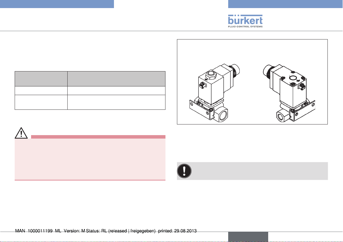
Model with over-
stretched coil
The solenoid coils are mounted on the fitting using either 4 cylinder
head screws M4 x 58 (flange model) or a central attachment
M14 x 1.5 (overstretched model).
The solenoid coils may be removed by the manufacturer
only!
The valves always represent a closed system.
Block-screwed
model
english
9
Page 10
PTB 02 ATEX 2173 X
Technical Data
5.10. Model with a terminal box
DANGER!
Danger of explosion!
• Only specified cables and lines may be used.
• The operator must ensure an adequate strain relief.
• Lines with an outer diameter from 6 mm to 13 mm may be used.
Observe the maximum thermal load of the installed cables and lines.
• The inserted seal must be adjusted to the diameter of the cable /
line.
• The rated cross-section of the cables / line cores must be at least
0.75 mm² and must not exceed 2.5 mm².
• Screws for attaching the cover of the terminal box must be tightened to a torque of 100 Ncm (± 5 %).
The solenoid coils can be designed with a terminal box (optionally with /
without fuse) (fuse according to separate type-examination certificate).
The attachment of a terminal box changes the ignition protection type
of these solenoid coils.
Identification with attached terminal box:
II 2G EX em II T3, T4 or T5
The label on the cover:
Do not open unless isolated from power supply! is intended to
prevent the cover from being opened unintentionally.
6. TECHNICAL DATA
6.1. Conformity
The device conforms to the EC directives according to the EC
Declaration of Conformity.
6.2. Standards
The conformity with EC guidelines is guaranteed in accordance with
standards:
• EN 60079-0, EN 60079-7, EN 60079-18.
6.3. Licenses
The EC type-examination certificate PTB 02 ATEX 2173 X was
issued by the
PTB (Physikalisch Technische Bundesanstalt)
Bundesallee 100
38116 Braunschweig (Germany)
which also audits production (CE 102).
The EC type-examination certificate can be found on the Internet at:
www.burkert.com
10
english
Page 11
PTB 02 ATEX 2173 X
Technical Data
6.4. Operating Conditions
WARNING!
Danger of explosion!
It is highly risky to exceed the technical data indicated on the
rating plate!
• Never exceed the technical data indicated on the rating plate.
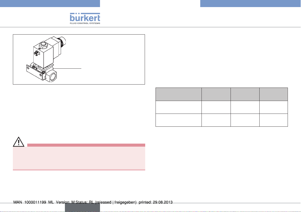
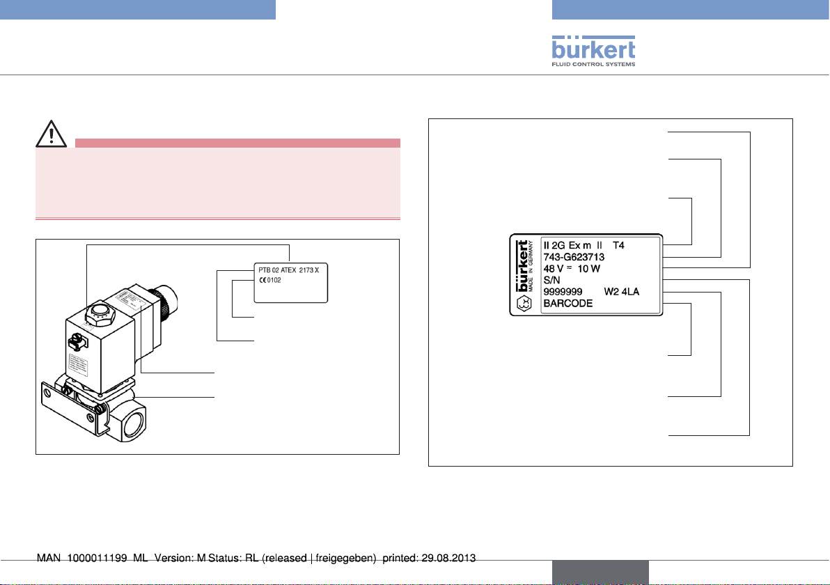
CE identification
PTB approval number
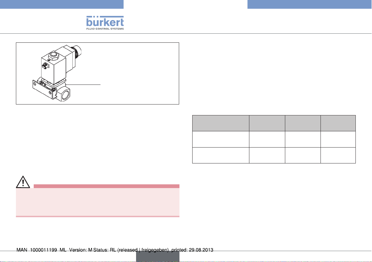
Rating plate
Fuse
... A
Fig. 1: Location of the rating plate
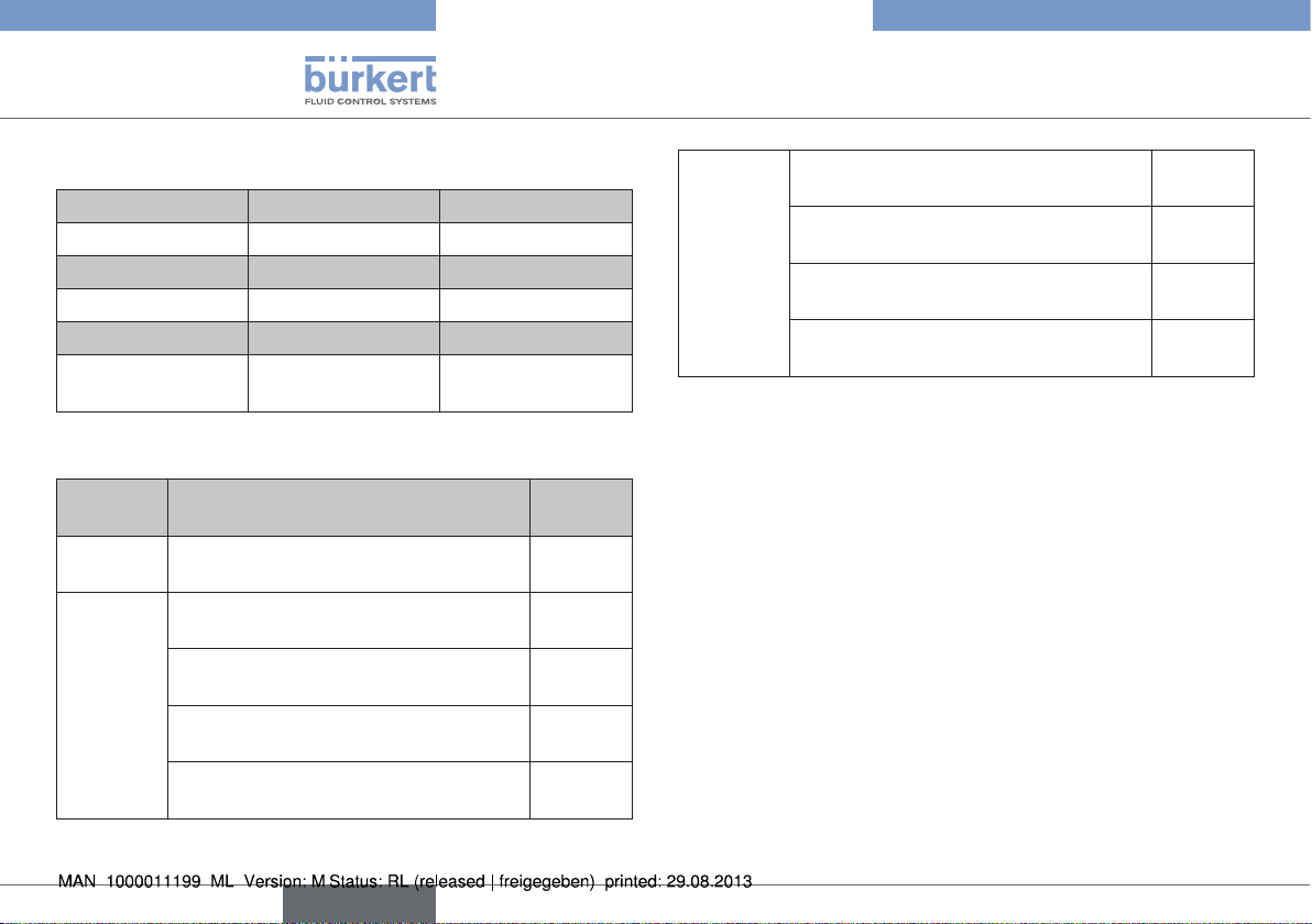
6.4.1. Rating plate
Voltage (± 10 %) - power
Coil type - connection size for fluid
part coil size
Protection class / temperature class
Place for barcode
Identification number of the coil
Serial number of the coil
Fig. 2: Description on the rating plate
english
11
Page 12
PTB 02 ATEX 2173 X
Technical Data
6.5. Electrical Data
Type
Temperature class
Current type
Nominal voltage
Rated current
Power limit in
equilibrium
74. 75.
T4 T3 or T5
AC/DC AC/DC
12 ... 240 V 12 ... 240 V
1,00 ... 0,028 A 0,63 ... 0,028 A
10 W 7 W
6.6. Electrical connection
Identifi-
cation
A *
L
Permanently installed rubber hose line of
type H05 RN-F3G0,75
** Terminal box with cable gland
M20 x 1.5 without fuse
Terminal box with threaded nipple
M20 x 1.5 without fuse
Terminal box with threaded nipple
NPT 1/2 without fuse
Terminal box with threaded nipple G 1/2
without fuse
Design Internal
code
Not
specified
JA02
JA08
JA09
JA10
** Terminal box with cable gland
M20 x 1.5 and fuse
Terminal box with threaded nipple
K ***
* The connection line of the electromagnet type 7. must be permanently
installed in such a way that it is adequately protected from mechanical
damage.
** Cable gland according to separate type-examination certificate.
*** Fuse according to separate type-examination certificate.
M20 x 1.5 and fuse
Terminal box with threaded nipple
NPT 1/2 and fuse
Terminal box with threaded nipple G 1/2
and fuse
JA01
JA05
JA06
JA07
12
english
Page 13
PTB 02 ATEX 2173 X
Assembly
7. ASSEMBLY
7.1. Safety instructions
DANGER!
Danger of explosion!
The device is a closed system. It must not be removed.
The following safety instructions must be observed:
• The surface of the device may become electrostatically charged.
In potentially explosive areas the surface of the devices may be
cleaned with a damp or an anti-static cloth only.
• Only specified cables and lines may be used.
• The operator must ensure an adequate strain relief.
• Lines with an outer diameter of 6 mm - 13 mm can be used.
Observe the maximum thermal load of the installed cables and
lines.
• The inserted seal must be adjusted to the diameter of the cable
/ line.
The rated cross-section of the cables / line cores must be at
least 0.75 mm² and must not exceed 2.5 mm².
• Screws for attaching the cover of the terminal box must be
tightened to a torque of 100 Ncm (± 5 %).
DANGER!
Risk of electric shock!
Acute risk of injury from hazardous body voltage! Risk of damaging
the device by short-circuit!
• Before reaching into the device or the equipment, switch off the
power supply and secure to prevent reactivation!
• Live terminals in the terminal box may cause an electric shock,
short-circuit or explosion. Switch off the power supply. Only then
open the terminal box.
• The connection lines of the electromagnets must be permanently
installed in such a way that they are adequately protected from
mechanical damage.
• Observe applicable accident prevention and safety regulations
for electrical equipment!
WARNING!
Danger – high pressure!
When reaching into the system, there is an acute risk of injury.
• Before dismounting pneumatic lines and valves, turn off the
pressure and vent the lines.
• During the installation, make certain the flow direction is correct.
• Observe applicable accident prevention and safety regulations
for pressurized devices.
english
13
Page 14
PTB 02 ATEX 2173 X
Start-Up
7.2. Installation of type 0742
Any installation position.
Preferably with magnet system face up.
1. Clean pipelines.
2. Any installation position
→ Preferential direction with actuator face up.
3. Connect dirt trap upstream
→ Observe direction of flow!
4. Seal
→ PTFE.
5. Screw in pipelines
→ Observe direction of flow!
6. Install / remove.
NOTE!
Information for devices with connecting cable:
Connecting cable and coil are encapsulated. They must not be
removed!
Always connect protective conductor!
7. Connect to power supply.
8. START-UP
8.1. Safety instructions
WARNING!
Risk of injury from improper operation!
Improper operation may result in injuries as well as damage to the
device and the area around it.
• Before start-up, ensure that the operating personnel are familiar
with and completely understand the contents of the operating
instructions.
• Observe the safety instructions and intended use.
• Only adequately trained personnel may start up the equipment/
the device.
8.2. Start-Up
Before starting up the device, ensure that:
• the device has been installed correctly,
• the connection has been made properly,
• the device is not damaged,
• all screws have been tightened.
14
english
Page 15

PTB 02 ATEX 2173 X
Maintenance, Troubleshooting
9. MAINTENANCE,
TROUBLESHOOTING
9.1. Safety instructions
WARNING!
Danger of explosion caused by electrostatic charge!
If there is a sudden discharge from electrostatically charged
devices or persons, there is a danger of explosion in the EX area.
• Using suitable measures, ensure that no electrostatic charges
can occur in the EX area.
• Clean the device surface by gently wiping it with a damp or antistatic cloth only.
Risk of injury from improper servicing, repairs and
maintenance!
• The device may be serviced and maintained by authorized technicians only and with the appropriate tools!
• The unit may be repaired by the manufacturer only!
• When repairing or servicing the system, the valve must not be
opened and the protective conductor connection must not be
disconnected!
9.2. Maintenance Work
The devices are maintenance-free when operated under the conditions described in this manual.
9.3. Troubleshooting
If malfunctions occur, ensure that:
• the device has been installed correctly,
• the connection has been made properly,
• the device is not damaged,
• all screws have been tightened,
• the voltage and pressure have been switched on,
• the pipelines are free.
english
15
Page 16

10. TRANSPORT, STORAGE,
DISPOSAL
NOTE!
Transport damages!
Inadequately protected equipment may be damaged during
transport.
• During transportation protect the device against wet and dirt in
shock-resistant packaging.
• Avoid exceeding or dropping below the allowable storage
temperature.
Incorrect storage may damage the device.
• Store the device in a dry and dust-free location!
• Storage temperature: -40 … +55 °C.
Damage to the environment caused by device components
contaminated with media.
• Ensure the device and packaging are disposed of in an environmentally sound manner.
• Observe applicable regulations relating to refuse disposal and
the environment.
PTB 02 ATEX 2173 X
Transport, Storage, Disposal
16
english
Page 17

PTB 02 ATEX 2173 X
Inhaltsverzeichnis
1. DIE BEDIENUNGSANLEITUNG ............................................................ 18
1.1. Darstellungsmittel ...........................................................................18
2. BESTIMMUNGSGEMÄSSE VERWENDUNG ...................................19
2.1. Beschränkungen ............................................................................19
2.2. EX Zulassung ..................................................................................19
3. GRUNDLEGENDE SICHERHEITSHINWEISE ................................. 20
4. ALLGEMEINE HINWEISE .......................................................................... 21
4.1. Kontaktadresse ...............................................................................21
4.2. Gewährleistung...............................................................................21
4.3. Informationen im Internet ..............................................................21
5. EINSATZBEDINGUNGEN DER GERÄTE........................................... 21
5.1. Kurzschlussschutz ..........................................................................21
5.2. Betrieb nur mit zugehörigem Ventil ............................................22
5.3. Zündschutzart .................................................................................22
5.4. Abmessungen .................................................................................22
5.5. Schutzart ..........................................................................................22
5.6. Einzelmontage .................................................................................22
5.7. Einsatztemperaturbereich .............................................................22
5.8. Maximal zulässiger Umgebungstemperatur .............................23
5.9. Einsatz in Tanksäulen.....................................................................23
5.10. Ausführung mit einem Klemmenkasten ...................................24
6. TECHNISCHE DATEN ................................................................................24
6.1. Konformität .......................................................................................24
6.2. Normen .............................................................................................24
6.3. Zulassungen ....................................................................................24
6.4. Betriebsbedingungen ....................................................................25
6.5. Elektrische Daten ...........................................................................26
6.6. Elektrischer Anschluss ..................................................................26
7. MONTAGE ........................................................................................................27
7.1. Sicherheitshinweise .......................................................................27
7.2. Montage des Typs 0742 ..............................................................28
8. INBETRIEBNAHME ...................................................................................... 28
8.1. Sicherheitshinweise .......................................................................28
8.2. Inbetriebnahme ...............................................................................28
9. WARTUNG, FEHLERBEHEBUNG .........................................................29
9.1. Sicherheitshinweise .......................................................................29
9.2. Wartungsarbeiten ...........................................................................29
9.3. Fehlerbehebung ..............................................................................29
10. TRANSPORT, LAGERUNG, VERPACKUNG .................................. 30
deutsch
17
Page 18

PTB 02 ATEX 2173 X
Die Bedienungsanleitung
1. DIE BEDIENUNGSANLEITUNG
Die Bedienungsanleitung beschreibt den gesamten Lebenszyklus
des Gerätes. Bewahren Sie diese Anleitung so auf, dass sie für jeden
Benutzer gut zugänglich ist und jedem neuen Eigentümer des Gerätes
wieder zur Verfügung steht.
Die Bedienungsanleitung enthält wichtige Informationen zur
Sicherheit!
Das Nichtbeachten dieser Hinweise kann zu gefährlichen Situationen
führen.
• Die Bedienungsanleitung muss gelesen und verstanden werden.
1.1. Darstellungsmittel
GEFAHR!
Warnt vor einer unmittelbaren Gefahr!
• Bei Nichtbeachtung sind Tod oder schwere Verletzungen die
Folge.
WARNUNG!
Warnt vor einer möglicherweise gefährlichen Situation!
• Bei Nichtbeachtung drohen schwere Verletzungen oder Tod.
VORSICHT!
Warnt vor einer möglichen Gefährdung!
• Nichtbeachtung kann mittelschwere oder leichte Verletzungen
zur Folge haben.
HINWEIS!
Warnt vor Sachschäden!
• Bei Nichtbeachtung kann das Gerät oder die Anlage beschädigt
werden.
Bezeichnet wichtige Zusatzinformationen, Tipps und
Empfehlungen.
Verweist auf Informationen in dieser Bedienungsanleitung
oder in anderen Dokumentationen.
→ markiert einen Arbeitsschritt, den Sie ausführen müssen.
18
deutsch
Page 19

PTB 02 ATEX 2173 X
Bestimmungsgemäße Verwendung
2. BESTIMMUNGSGEMÄSSE
VERWENDUNG
Bei nicht bestimmungsgemäßem Einsatz des Gerätes Typ 0742
können Gefahren für Personen, Anlagen in der Umgebung und
die Umwelt entstehen.
• Das Gerät dient ausschließlich als Magnetventil für die laut Datenblatt zulässigen Medien und für den Einsatz in Explosionsgruppe
II, Kategorie 2G und Temperaturklasse T4 (T3 bei +55 °C) oder
T5 (siehe Angaben auf dem
• Das Gerät darf nur für die im Kapitel „5. Einsatzbedingungen
der Geräte“ vorgesehenen Einsatzfälle und in Verbindung mit
von Bürkert empfohlenen bzw. zugelassenen Fremdgeräten und
-komponenten verwendet werden. Für den Einsatz die in den
Vertragsdokumenten und der Bedienungsanleitung spezifizierten
zulässigen Daten, Betriebs- und Einsatzbedingungen beachten.
• Die angewandte Schutzart ist die Vergusskapselung EX „m“ für
Spulen mit Kabelanschluss oder die Vergusskapselung mit erhöhter Sicherheit EX „em“ für Spulen mit Klemmenkasten.
• Der einwandfreie und sichere Betrieb des Systems setzt
sachgemäßen Transport, sachgemäße Lagerung und Installation sowie sorgfältige Bedienung und Instandhaltung voraus.
Eine andere oder darüber hinausgehende Benutzung gilt als nicht
bestimmungsgemäß. Für hieraus resultierende Schäden haftet
Bürkert nicht. Das Risiko trägt allein der Anwender.
• Das Gerät nur bestimmungsgemäß einsetzen.
Zulassungsschild).
2.1. Beschränkungen
Bei der Ausfuhr des Systems/Gerätes gegebenenfalls bestehende
Beschränkungen beachten.
2.2. EX Zulassung
Die EX Zulassung ist nur gültig, wenn die von Bürkert zugelassenen
Module und Komponenten so verwendet werden, wie es in dieser
Bedienungsanleitung beschrieben ist.
Der Typ 0742 darf nur in Kombination mit den von Bürkert freigegebenen Zusatzkomponenten eingesetzt werden, andernfalls erlischt die
EX Zulassung!
Bei unzulässigen Veränderungen am Gerät, Modulen oder Komponenten, erlischt die EX Zulassung ebenfalls.
Temperaturklassen und elektrische Daten siehe Kapitel
„6. Technische Daten“.
deutsch
19
Page 20

3. GRUNDLEGENDE
SICHERHEITSHINWEISE
Diese Sicherheitshinweise berücksichtigen keine
• Zufälligkeiten und Ereignisse, die bei Montage, Betrieb und Wartung
der Geräte auftreten können.
• ortsbezogenen Sicherheitsbestimmungen, für deren Einhaltung, auch
in Bezug auf das Montagepersonal, der Betreiber verantwortlich ist.
Explosionsgefahr!
• Das Gerät ist Teil eines geschlossenen Systems und darf nicht
während des Betriebs demontiert werden.
Gefahr durch elektrische Spannung!
Akute Verletzungsgefahr durch gefährliche Körperspannung!
Gefahr der Beschädigung des Gerätes durch Kurzschluss!
• Vor Eingriffen in das Gerät oder die Anlage, Spannung abschalten
und vor Wiedereinschalten sichern!
• Die geltenden Unfallverhütungs- und Sicherheitsbestimmungen
für elektrische Geräte beachten!
Gefahr durch hohen Druck!
Bei Eingriffen in das System besteht akute Verletzungsgefahr.
• Vor dem Lösen von Leitungen und Ventilen den Druck abschalten
und die Leitungen entlüften.
• Beim Einbau die Durchflussrichtung beachten.
• Die geltenden Unfallverhütungs- und Sicherheitsbestimmungen
für druckbeaufschlagte Geräte einhalten.
PTB 02 ATEX 2173 X
Grundlegende Sicherheitshinweise
Explosionsgefahr durch elektrostatische Aufladung!
Bei plötzlicher Entladung elektrostatisch aufgeladener Geräte oder
Personen besteht im EX-Bereich Explosionsgefahr.
• Durch geeignete Maßnahmen sicherstellen, dass es im EX Bereich zu keinen elektrostatischen Aufladungen kommen kann.
• Die Geräteoberfläche nur durch leichtes Abwischen mit einem
feuchten oder antistatischen Tuch reinigen.
Allgemeine Gefahrensituationen.
Zum Schutz vor Verletzungen ist zu beachten:
• Dass die Anlage nicht unbeabsichtigt betätigt werden kann.
• Installations- und Instandhaltungsarbeiten dürfen nur von autorisiertem Fachpersonal mit geeignetem Werkzeug ausgeführt
werden.
• Nach einer Unterbrechung der elektrischen oder pneumatischen
Versorgung ist ein definierter oder kontrollierter Wiederanlauf des
Prozesses zu gewährleisten.
• Das Gerät darf nur in einwandfreiem Zustand und unter Beachtung
der Bedienungsanleitung betrieben werden.
• Für die Einsatzplanung und den Betrieb des Gerätes müssen die
allgemeinen Regeln der Technik eingehalten werden.
Bei Nichtbeachtung dieser Bedienungsanleitung und ihrer
Hinweise sowie bei unzulässigen Eingriffen in das Gerät entfällt
jegliche Haftung unsererseits, ebenso erlischt die Gewährleistung auf Geräte und Zubehörteile!
20
deutsch
Page 21

PTB 02 ATEX 2173 X
Allgemeine Hinweise
4. ALLGEMEINE HINWEISE
4.1. Kontaktadresse
Deutschland
Bürkert Fluid Control Systems
Sales Center
Christian-Bürkert-Str. 13-17
D-74653 Ingelfingen
Tel. + 49 (0) 7940 - 10 91 111
Fax + 49 (0) 7940 - 10 91 448
E-mail: info@de.buerkert.com
International
Die Kontaktadressen finden Sie auf den letzten Seiten der gedruckten
Bedienungsanleitung.
Außerdem im Internet unter: www.burkert.com
4.2. Gewährleistung
Voraussetzung für die Gewährleistung ist der bestimmungsgemäße Gebrauch des Gerätes unter Beachtung der spezifizierten
Einsatzbedingungen.
4.3. Informationen im Internet
Bedienungsanleitungen und Datenblätter zum Typ 0742 finden Sie im
Internet unter: www.buerkert.de
5. EINSATZBEDINGUNGEN DER
GERÄTE
5.1. Kurzschlussschutz
Jedem Magneten muss als Kurzschlussschutz eine seinem Bemessungsstrom entsprechende Sicherung (max. 3 x Ib nach IEC 601272-1) bzw. ein Motorschutzschalter mit Kurzschluss- und thermischer
Schnellauslösung (Einstellung auf Bemessungsstrom) vorgeschaltet
werden. Bei sehr kleinen Bemessungsströmen des Magneten ist die
Sicherung mit dem kleinsten Stromwert nach der genannten IEC-Norm
ausreichend. Diese Sicherung darf im zugehörigen Versorgungsgerät
untergebracht sein oder muss separat vorgeschaltet werden. Die
Sicherungs-Bemessungsspannung muss gleich oder größer als die
angegebene Nennspannung des Magneten sein. Das Ausschaltvermögen des Sicherungseinsatzes muss gleich oder größer als der
maximal anzunehmende Kurzschlussstrom am Einbauort (üblicherweise
1500 A) sein.
Bei der Ausführung A und L des Elektromagneten muss der Kurzschlussschutz durch den Betreiber gewährleistet werden. Bei Ausführung K des Elektromagneten ist die Sicherung im Klemmenkasten
des Gerätes eingebaut.
Nähere Beschreibung der Ausführungen A, L und K siehe
Kapitel „6. Technische Daten“.
deutsch
21
Page 22
Sicherung / Fuse
...A
5.2. Betrieb nur mit zugehörigem
Ventil
Die Magnetspulen Typ 74. / 75. dürfen nur mit zugehörigem Ventilkörper als Komplettgerät betrieben werden, der folgenden Forderungen
entspricht:
• Werkstoffe bei Einzel- und Blockmontage:
Metall (Messing, Aluminium, Edelstahl) oder Kunststoff (z. B.
Polyamid PA 6 GV).
GEFAHR!
Explosionsgefahr!
• Bei Einsatz der Geräte in Tanksäulen zur Steuerung von Benzin als
Kategorie 2 muss ein Ventilkörper aus Metall (Messing, Aluminium
oder Edelstahl) verwendet werden.
Mindestbemessungen der Ventilkörper:
• 40 mm x 40 mm x 10 mm (L x B x H)
Ein größerer Ventilkörper mit besserer Wärmeleitfähigkeit darf
jeder Zeit angebaut werden.
PTB 02 ATEX 2173 X
Einsatzbedingungen der Geräte
5.3. Zündschutzart
• Bei Ausführung mit eingebauter Gummischlauchleitung (A):
EX m II T4 (T3 bei +55 °C) bzw. T5 nach EN 60079-0,
EN 60079-18.
• Bei Ausführung mit Klemmenkasten (L und K): EX em II T4
(T3 bei +55 °C) bzw. T5 nach EN 60079-0, EN 60079-7 und
EN 60079-18.
5.4. Abmessungen
Anschlussart Länge
Elektrischer
Anschluss A
Elektrischer
Anschluss L und K
(mm)
106 40 58
121 60 113
Breite
(mm)
Höhe
(mm)
5.5. Schutzart
IP65 nach EN 60529.
5.6. Einzelmontage
Die Magnetspulen Typ 74. / 75. sind nur zur Einzelmontage geeignet.
5.7. Einsatztemperaturbereich
Für jeden Typ den bei den Elektrischen Daten aufgeführten Einsatztemperaturbereich beachten.
22
deutsch
Page 23

PTB 02 ATEX 2173 X
Einsatzbedingungen der Geräte
5.8. Maximal zulässiger
Umgebungstemperatur
Bitte beachten Sie für jeden Typ den unter Einsatzbedingungen der
Spule angegeben, maximal zulässigen Umgebungstemperatur!
Ausführung Maximal zulässiger
Umgebungstemperatur
74. -40 ... +40 °C
75. -40 ... +50 °C
(-40 ... +55 °C, wenn T3)
5.9. Einsatz in Tanksäulen
GEFAHR!
Explosionsgefahr durch Öffnen des Gerätes!
• Das Gerät ist ein geschlossenes System. Es darf nicht demontiert
werden!
Explosionsgefahr!
• Bei Einsatz der Geräte in Tanksäulen zur Steuerung von Benzin als
Kategorie 2 muss ein Ventilkörper aus Metall (Messing, Aluminium
oder Edelstahl) verwendet werden.
Die Geräte dürfen auch zur Steuerung von Benzin in Kategorie 2 eingesetzt werden, wenn in dem geschlossenen System keine Luft und
kein Sauerstoff vorhanden ist.
Dies gilt auch beim Anfahren und Abschalten des Systems.
Ausführung mit
übergestreckter
Spule
Die Magnetspulen werden entweder mit 4 Zylinderschrauben
M4 x 58 (Flanschausführung) oder Zentralbefestigung M14 x 1,5
(Übersteckausführung) auf die Armatur montiert.
Die Magnetspulen dürfen nur vom Hersteller demontiert
werden!
Die Ventile stellen immer ein geschlossenes System dar.
Blockverschraubte
Ausführung
deutsch
23
Page 24

PTB 02 ATEX 2173 X
Technische Daten
5.10. Ausführung mit einem
Klemmenkasten
GEFAHR!
Explosionsgefahr!
• Nur festgelegte Kabel und Leitungen dürfen eingeführt werden.
• Betreiber muss eine entsprechende Zugentlastung gewährleisten.
• Es können Leitungen mit Außendurchmesser von 6 mm bis 13 mm
verwendet werden. Die maximale thermische Belastung der eingeführten Kabel bzw. Leitungen beachten.
• Die eingelegte Dichtung muss dem Durchmesser des Kabels /
der Leitung angepasst werden.
• Der Bemessungsquerschnitt der Kabel / Leitungsadern muss mindestens 0,75 mm² betragen und darf 2,5 mm² nicht überschreiten.
• Schrauben zur Befestigung des Deckels des Klemmenkastens
müssen mit einem Drehmoment von 100 Ncm (± 5 %) angezogen
werden.
Die Magnetspulen können mit einem Klemmenkasten (wahlweise mit /
ohne Sicherung) ausgeführt werden (Sicherung nach getrennter Baumusterprüfbescheinigung). Durch den Anbau eines Klemmenkastens
ändert sich die Zündschutzart dieser Magnetspulen.
Kennzeichnung mit angebautem Klemmenkasten:
II 2G EX em II T3, T4 oder T5
Als Schutz gegen unbeabsichtiges Öffnen des Deckels trägt dieser
die Aufschrift:
Nur spannungsfrei öffnen!
6. TECHNISCHE DATEN
6.1. Konformität
Das Gerät ist konform zu den EG-Richtlinien entsprechend der
EG-Konformitätserklärung.
6.2. Normen
Durch folgende Normen wird die Konformität mit den EG-Richtlinien
erfüllt:
• EN 60079-0, EN 60079-7, EN 60079-18.
6.3. Zulassungen
Die EG-Baumusterprüfbescheinigung PTB 02 ATEX 2173 X wurde
von der
PTB (Physikalisch Technische Bundesanstalt)
Bundesallee 100
38116 Braunschweig
ausgestellt, die auch die Fertigung auditiert (CE 102).
Die EG-Baumusterprüfbescheinigung finden Sie im Internet unter:
www.buerkert.de
24
deutsch
Page 25

PTB 02 ATEX 2173 X
Technische Daten
6.4. Betriebsbedingungen
WARNUNG!
Explosionsgefahr!
Überschreitung der auf dem Typenschild angegebenen technischen
Daten führt zu hohem Risiko!
• Auf dem Typenschild angegebenen technischen Daten keinesfalls überschreiten.
CE - Kennzeichnung
PTB - Zulassungsnummer
Typenschild
Sicherung / Fuse
... A
Bild 1: Lage des Typenschildes
6.4.1. Typenschild
Spannung (± 10 %) - Leistung
Spulentyp - Anschlussgröße für
Fluidteil - Spulengröße
Schutzart / Temperaturklasse
Platz für Barcode
Identnummer der Spule
Seriennummer der Spule
Bild 2: Beschreibung des Typenschildes
deutsch
25
Page 26

PTB 02 ATEX 2173 X
Technische Daten
6.5. Elektrische Daten
Typ
Temperaturklasse
Stromart
Nennspannung
Bemessungsstrom
Grenzleistung im
Beharrungszustand
74. 75.
T4 T3 oder T5
AC/DC AC/DC
12 ... 240 V 12 ... 240 V
1,00 ... 0,028 A 0,63 ... 0,028 A
10 W 7 W
6.6. Elektrischer Anschluss
Kenn-
zeichnung
A *
L
Fest eingebaute Gummischlauchleitung
des Typs H05 RN-F3G0,75
** Klemmenkasten mit Kabelverschraubung M20 x 1,5 ohne Sicherung
Klemmenkasten mit Gewindenippel M20 x
1,5 ohne Sicherung
Klemmenkasten mit Gewindenippel NPT
1/2 ohne Sicherung
Klemmenkasten mit Gewindenippel G 1/2
ohne Sicherung
Ausführung Interner
Code
ohne
Angabe
JA02
JA08
JA09
JA10
** Klemenkasten mit Kabelverschraubung
M20 x 1,5 und Sicherung
Klemmenkasten mit Gewindenippel M20 x
K ***
* Die Anschlussleitung des Elektromagneten Typ 7. muss fest und so verlegt
werden, dass sie vor mechanischen Beschädigungen hinreichend geschützt
ist.
** Kabelverschraubung nach getrennter Baumusterprüfbescheinigung.
*** Sicherung nach getrennter Baumusterprüfbescheinigung.
1,5 und Sicherung
Klemmenkasten mit Gewindenippel NPT
1/2 und Sicherung
Klemmenkasten mit Gewindenippel G 1/2
und Sicherung
JA01
JA05
JA06
JA07
26
deutsch
Page 27

PTB 02 ATEX 2173 X
Montage
7. MONTAGE
7.1. Sicherheitshinweise
GEFAHR!
Explosionsgefahr!
Das Gerät ist ein geschlossenes System. Es darf nicht demontiert
werden.
Folgende Sicherheitshinweise sind einzuhalten:
• Die Oberfläche des Gerätes kann sich elektrostatisch aufladen. In
explosionsgefährdeten Bereichen darf die Oberfläche der Geräte
nur mit einem feuchten oder antistatischen Tuch gereinigt werden.
• Nur festgelegte Kabel und Leitungen dürfen eingeführt werden.
• Betreiber muss eine entsprechende Zugentlastung gewährleisten.
• Leitungen mit Außendurchmesser von 6 mm ... 13 mm können
verwendet werden. Die maximale thermische Belastung der eingeführten Kabel bzw. Leitungen beachten.
• Die eingelegte Dichtung muss dem Durchmesser des Kabels /
der Leitung angepasst werden.
Der Bemessungsquerschnitt der Kabel / Leitungsadern
muss mindestens 0,75 mm² betragen und darf 2,5 mm² nicht
überschreiten.
• Die Schrauben zur Befestigung des Deckels des Klemmenkastens
müssen mit einem Drehmoment von 100 Ncm (± 5 %) angezogen
werden.
GEFAHR!
Gefahr durch elektrische Spannung!
Akute Verletzungsgefahr durch gefährliche Körperspannung!
Gefahr der Beschädigung des Gerätes durch Kurzschluss!
• Vor Eingriffen in das Gerät oder die Anlage, Spannung abschalten
und vor Wiedereinschalten sichern!
• Spannungsführende Klemmen im Klemmenkasten können Stromschlag, Kurzschluss oder Explosion verursachen. Spannung
abschalten. Erst dann den Klemmenkasten öffnen.
• Die Anschlussleitungen der Elektromagneten müssen fest und
so verlegt werden, dass sie vor mechanischen Beschädigungen
hinreichend geschützt sind.
• Die geltenden Unfallverhütungs- und Sicherheitsbestimmungen
für elektrische Geräte beachten!
WARNUNG!
Gefahr durch hohen Druck!
Bei Eingriffen in das System besteht akute Verletzungsgefahr.
• Vor dem Lösen von Leitungen und Ventilen den Druck abschalten und die Leitungen entlüften.
• Beim Einbau die Durchflussrichtung beachten.
• Die geltenden Unfallverhütungs- und Sicherheitsbestimmungen
für druckbeaufschlagte Geräte einhalten.
deutsch
27
Page 28

PTB 02 ATEX 2173 X
Inbetriebnahme
7.2. Montage des Typs 0742
Einbaulage beliebig.
Vorzugsweise mit Magnetsystem oben.
1. Rohrleitungen reinigen.
2. Einbaulage beliebig
→ Vorzugsrichtung mit Antrieb oben.
3. Schmutzfänger vorschalten
→ Durchflussrichtung beachten!
4. Abdichtung
→ PTFE.
5. Rohrleitungen einschrauben
→ Durchflussrichtung beachten!
6. Montieren / Demontieren.
HINWEIS!
Hinweis für Geräte mit Anschlusskabel:
Anschlusskabel und Spule sind vergossen. Sie dürfen nicht
demontiert werden!
Schutzleiter immer anschließen!
7. Elektrisch anschließen.
8. INBETRIEBNAHME
8.1. Sicherheitshinweise
WARNUNG!
Verletzungsgefahr bei unsachgemäßem Betrieb!
Nicht sachgemäßer Betrieb kann zu Verletzungen, sowie Schäden
am Gerät und seiner Umgebung führen.
• Vor der Inbetriebnahme muss gewährleistet sein, dass der Inhalt
der Bedienungsanleitung dem Bedienungspersonal bekannt ist
und vollständig verstanden wurde.
• Die Sicherheitshinweise und die bestimmungsgemäße Verwendung müssen beachtet werden.
• Nur ausreichend geschultes Personal darf die Anlage/das Gerät
in Betrieb nehmen.
8.2. Inbetriebnahme
Vor Inbetriebnahme sicherstellen, dass:
• das Gerät vorschriftsmäßig installiert wurde,
• der Anschluss ordnungsgemäß ausgeführt wurde,
• das Gerät nicht beschädigt ist,
• alle Schrauben fest angezogen sind.
28
deutsch
Page 29

PTB 02 ATEX 2173 X
Wartung, Fehlerbehebung
9. WARTUNG,
FEHLERBEHEBUNG
9.1. Sicherheitshinweise
WARNUNG!
Explosionsgefahr durch elektrostatische Aufladung!
Bei plötzlicher Entladung elektrostatisch aufgeladener Geräte oder
Personen besteht im EX-Bereich Explosionsgefahr.
• Durch geeignete Maßnahmen sicherstellen, dass es im EXBereich zu keinen elektrostatischen Aufladungen kommen kann.
• Die Geräteoberfläche nur durch leichtes Abwischen mit einem
feuchten oder antistatischen Tuch reinigen.
Verletzungsgefahr bei unsachgemäßen Wartungs-, Reparatur
und Instandhaltungsarbeiten!
• Die Wartungs- und Instandhaltungsarbeiten am Gerät dürfen nur
autorisiertes Fachpersonal mit geeignetem Werkzeug durchführen!
• Reparaturen am Gerät dürfen nur vom Hersteller durchgeführt
werden!
• Bei Repatatur- oder Wartungsarbeiten an der Anlage darf das
Ventil nicht geöffnet und die Schutzleiterverbindung nicht getrennt
werden!
9.2. Wartungsarbeiten
Die Geräte sind beim Betrieb unter den in dieser Anleitung beschriebenen Bedingungen wartungsfrei.
9.3. Fehlerbehebung
Bei Störungen sicherstellen, dass:
• das Gerät vorschriftsmäßig installiert wurde,
• der Anschluss ordnungsgemäß ausgeführt wurde,
• das Gerät nicht beschädigt ist,
• alle Schrauben fest angezogen sind,
• Spannung und Druck anliegen,
• die Rohrleitungen frei sind.
deutsch
29
Page 30

10. TRANSPORT, LAGERUNG,
VERPACKUNG
HINWEIS!
Transportschäden!
Unzureichend geschützte Geräte können durch den Transport
beschädigt werden.
• Gerät vor Nässe und Schmutz geschützt in einer stoßfesten
Verpackung transportieren.
• Eine Über- bzw. Unterschreitung der zulässigen Lagertemperatur vermeiden.
Falsche Lagerung kann Schäden am Gerät verursachen.
• Gerät trocken und staubfrei lagern!
• Lagertemperatur. -40 … +55 °C.
Umweltschäden durch von Medien kontaminierte Geräteteile.
• Gerät und Verpackung umweltgerecht entsorgen!
• Geltende Entsorgungsvorschriften und Umweltbestimmungen
einhalten.
PTB 02 ATEX 2173 X
Transport, Lagerung, Verpackung
30
deutsch
Page 31

PTB 02 ATEX 2173 X
Table des matières
1. LES INSTRUCTIONS DE SERVICE .....................................................32
1.1. Symboles..........................................................................................32
2. UTILISATION CONFORME.......................................................................33
2.1. Limitations ........................................................................................33
2.2. Homologation EX ...........................................................................33
3. CONSIGNES DE SÉCURITÉ FONDAMENTALES .........................34
4. INDICATIONS GÉNÉRALES .................................................................... 35
4.1. Adresses ..........................................................................................35
4.2. Garantie légale ................................................................................35
4.3. Informations sur Internet ...............................................................35
5. CONDITIONS D’UTILISATION DE L’APPAREIL ............................. 35
5.1. Protection contre les courts-circuits .........................................35
5.2. Exploitation avec vanne correspondante ..................................36
5.3. Type de protection à l’allumage ..................................................36
5.4. Dimensions ......................................................................................36
5.5. Type de protection .........................................................................36
5.6. Montage individuel .........................................................................36
5.7. Plage de température d’utilisation ..............................................36
5.8. Température ambiante maximale autorisée ..............................37
5.9. Utilisation dans les pompes à essence .....................................37
5.10. Modèle avec coffret à bornes ...................................................38
6. CARACTÉRISTIQUES TECHNIQUES ................................................ 38
6.1. Conformité .......................................................................................38
6.2. Normes .............................................................................................38
6.3. Homologations ................................................................................38
6.4. Conditions d’exploitation ..............................................................39
6.5. Caractéristiques électriques ........................................................40
6.6. Raccordement électrique .............................................................40
7. MONTAGE ........................................................................................................41
7.1. Consignes de sécurité ..................................................................41
7.2. Montage du type 0742 .................................................................42
8. MISE EN SERVICE ....................................................................................... 42
8.1. Consignes de sécurité ..................................................................42
8.2. Mise en service ...............................................................................42
9. MAINTENANCE, DÉPANNAGE .............................................................. 43
9.1. Consignes de sécurité ..................................................................43
9.2. Travaux d’entretien .........................................................................43
9.3. Dépannage ......................................................................................43
10. TRANSPORT, STOCKAGE, ÉLIMINATION .....................................44
français
31
Page 32

PTB 02 ATEX 2173 X
Les instructions de service
1. LES INSTRUCTIONS DE
SERVICE
Les instructions de service décrivent le cycle de vie complet de l’appareil. Conservez ces instructions de sorte qu’elles soient accessibles
à tout utilisateur et à disposition de tout nouveau propriétaire.
Les instructions de service contiennent des informations
importantes sur la sécurité !
Le non-respect de ces consignes peut entraîner des situations
dangereuses.
• Les instructions de service doivent être lues et comprises.
1.1. Symboles
DANGER !
Met en garde contre un danger imminent !
• Le non-respect peut entraîner la mort ou de graves blessures.
AVERTISSEMENT !
Met en garde contre une situation éventuellement dangereuse !
• Risque de blessures graves, voire la mort en cas de non-respect.
ATTENTION !
Met en garde contre un risque possible !
• Le non-respect peut entraîner des blessures légères ou de
moyenne gravité.
REMARQUE !
Met en garde contre des dommages matériels !
• L’appareil ou l’installation peut être endommagé(e) en cas de
non-respect.
Désigne des informations supplémentaires importantes, des
conseils et des recommandations d’importance.
Renvoie à des informations dans ces instructions de service
ou dans d’autres documentations.
→ identifie une opération que vous devez effectuer.
32
français
Page 33

PTB 02 ATEX 2173 X
Utilisation conforme
2. UTILISATION CONFORME
L’utilisation non conforme de l’appareil du type 0742 peut présenter des dangers pour les personnes, les installations proches
et l’environnement.
• L’appareil sert exclusivement d’électrovanne pour les fluides autorisés par la fiche technique et pour l’utilisation dans les groupes
d’explosion II, catégorie 2G et classe de température T4 (T3 dans
+55 °C) ou T5 (voir les données sur la
• L’appareil peut être employé uniquement pour les cas individuels
prévus dans le chapitre « 5. Conditions d’utilisation de l’appareil »
et en association avec les appareils et composants étrangers
recommandés et homologués par Bürkert. Lors de l’utilisation,
il convient de respecter les données et conditions d’utilisation
et d’exploitation admissibles spécifiées dans les instructions de
service et dans les documents contractuels.
• Le type de protection employé est l’encapsulage EX « m » pour
bobines avec raccordement câble ou l’encapsulage avec sécurité
augmentée EX « m » pour bobines avec coffret à bornes.
• L’exploitation impeccable et sûre du système suppose un transport
conforme, un stockage et une installation conformes ainsi qu’une
utilisation et une maintenance soigneuses. Toute autre utilisation
est considérée comme non conforme. Bürkert n’est pas responsable des dommages en résultant. L’utilisateur est seul à en
supporter le risque.
• L’appareil doit être utilisé seulement de façon conforme.
plaque d’homologation).
2.1. Limitations
Lors de l’exportation du système / de l’appareil, veuillez respecter les
limitations éventuelles existantes.
2.2. Homologation EX
L’homologation EX n’est valable que si vous utilisez les modules et
composants homologués par Bürkert tel que cela est décrit dans ces
instructions de service.
Le type 0742 ne doit être utilisé qu’avec les composants supplémentaires autorisés par Bürkert, sinon l’homologation EX devient caduque.
En cas de modification non autorisée de l’appareil, des modules ou des
composants, l’homologation EX devient également caduque.
Classes de températures et données électriques, voir le
chapitre « 6. Caractéristiques techniques ».
français
33
Page 34

3. CONSIGNES DE SÉCURITÉ
FONDAMENTALES
Ces consignes de sécurité ne tiennent pas compte
• Des hasards et des événements pouvant survenir lors du montage,
de l’exploitation et de l’entretien des appareils.
• Des prescriptions de sécurité locales que l’exploitant est tenu de
faire respecter par le personnel chargé du montage.
Risque d’explosion !
• L’appareil fait partie d’un système clos et ne peut pas être démonté
pendant l’exploitation.
Danger présenté par la tension électrique !
Danger important de blessures par tensions dangereuses au niveau
du corps ! Danger d’endommagement de l’appareil par court-circuit !
• Avant d’intervenir dans l’appareil ou l’installation, couper la tension
et empêcher toute remise sous tension par inadvertance !
• Veuillez respecter les réglementations en vigueur pour les appareils
électriques en matière de prévention des accidents ainsi qu’en
matière de sécurité !
Danger dû à la haute pression !
Il y a risque important de blessures lors d’interventions sur le système.
• Avant de desserrer les conduites et les vannes, coupez la pression
et assurez l’échappement de l’air des conduites.
• Lors du montage, respectez le sens du débit.
• Veuillez respecter les réglementations en vigueur pour les appareils
sous pression en matière de prévention des accidents ainsi qu’en
matière de sécurité.
PTB 02 ATEX 2173 X
Consignes de sécurité fondamentales
Risque d’explosion dû à la charge électrostatique !
Il y a risque d’explosion en cas de décharge soudaine d’appareils
ou de personnes chargés d’électricité statique dans des zones
présentant des risques d’explosion.
• Assurez-vous par des mesures appropriées, qu’il ne peut y avoir
de charges électrostatiques dans de telles zones présentant
des risques d’explosion.
• Ne nettoyer la surface de l’appareil que par un essuyage léger
avec un chiffon humide ou antistatique.
Situations dangereuses d’ordre général.
Pour prévenir les blessures, respecter ce qui suit :
• L’installation ne peut pas être actionnée par inadvertance.
• Les travaux d’installation et de maintenance doivent être effectués
uniquement par des techniciens qualifiés et habilités disposant de
l’outillage approprié.
• Après une interruption de l’alimentation électrique ou pneumatique,
un redémarrage défini ou contrôlé du processus doit être garanti.
• L’appareil doit être utilisé uniquement en parfait état et en respectant les instructions de service.
• Les règles générales de la technique sont d’application pour planifier
l’utilisation et utiliser l’appareil.
Le non-respect de ces instructions de service avec ses
consignes ainsi que les interventions non autorisées sur l’appareil
excluent toute responsabilité de notre part et entraînent la nullité
de la garantie légale concernant les appareils et les accessoires !
34
français
Page 35

PTB 02 ATEX 2173 X
Indications générales
4. INDICATIONS GÉNÉRALES
4.1. Adresses
Allemagne
Bürkert Fluid Control Systems
Sales Center
Christian-Bürkert-Str. 13-17
D-74653 Ingelfingen
Tel. + 49 (0) 7940 - 10 91 111
Fax + 49 (0) 7940 - 10 91 448
E-mail : info@de.buerkert.com
International
Les adresses se trouvent aux dernières pages des instructions de
service imprimées.
Egalement sur internet sous : www.burkert.com
4.2. Garantie légale
La condition pour bénéficier de la garantie légale est l’utilisation
conforme de l’appareil dans le respect des conditions d’utilisation
spécifiées.
4.3. Informations sur Internet
Vous trouverez les instructions de service et les fiches techniques
concernant le type 0742 sur Internet sous www.buerkert.fr
5. CONDITIONS D’UTILISATION
DE L’APPAREIL
5.1. Protection contre les
courts-circuits
Pour assurer la protection contre les courts-circuits, il convient de
placer en amont de chaque aimant un fusible correspondant à son
courant évalué (maxi 3 x Ib selon CEI 60127-2-1) ou un disjoncteur-protecteur à déclenchement rapide thermique et de court-circuit (réglage
sur le courant évalué). Selon la norme CEI citée, le fusible à la valeur
de courant le plus faible suffit lorsque les courants mesurés de l’aimant
sont très faibles. Ce fusible peut être logé dans l’appareil d’alimentation
correspondant ou placé séparément en amont. La tension mesurée du
fusible doit être identique ou supérieure à la tension nominale indiquée
de l’aimant. La puissance de coupure du fusible doit être identique ou
supérieure au courant de court-circuit maximal possible sur le lieu de
montage (habituellement 1500 A).
Avec les modèles d’électro-aimants A et L, la protection court-circuit
doit être garantie par l’exploitant. Avec le modèle d’électro-aimant K,
la sécurité est montée dans le coffret à bornes de l’appareil.
Pour une description plus complète des modèles A, L et K,
voir le chapitre « 6. Caractéristiques techniques ».
français
35
Page 36

Sécurité / Fusible
...A
PTB 02 ATEX 2173 X
Conditions d’utilisation de l’appareil
5.3. Type de protection à l’allumage
• Avec les modèles avec flexible en caoutchouc (A) : EX m II T4 (T3
dans +55 °C) ou T5 selon EN 60079-0, EN 60079-18.
• Avec les modèles avec coffret à bornes (L et K) : EX em II T4 (T3
dans +55 °C) ou T5 selon EN 60079-0, EN 60079-7 et
EN 60079-18.
5.4. Dimensions
5.2. Exploitation avec vanne
correspondante
Les bobines magnétiques de type 74. / 75. ne doivent être exploitées
comme appareil complet qu’avec le corps de vanne adapté, qui remplit
les exigences suivantes :
• Matériaux en montage unique ou en bloc :
Métal (laiton, aluminium, inox) ou plastique (par ex. Polyamide PA
6 GV).
DANGER !
Risque d’explosion !
• Lors de l’utilisation des appareils dans des pompes à essence
pour la commande d’essence de catégorie 2, un corps de vanne
en métal (laiton, aluminium, inox) doit être employé.
Dimensionnements du corps de vanne :
• 40 mm x 40 mm x 10 mm (L x l x h)
Il est possible d’utiliser à tout moment un corps de soupape plus
grand avec une meilleure conductibilité thermique.
36
Type de
raccordement
Raccordement
électrique A
Raccordements
électriques L et K
Longueur
(mm)
106 40 58
121 60 113
Largeur
(mm)
Hauteur
(mm)
5.5. Type de protection
IP65 selon EN 60529.
5.6. Montage individuel
Seules les bobines magnétiques de type 74. / 75. sont adaptées au
montage individuel.
5.7. Plage de température d’utilisation
Respecter la plage de température d’utilisation indiquée dans les
données électriques pour chaque type.
français
Page 37

PTB 02 ATEX 2173 X
Conditions d’utilisation de l’appareil
5.8. Température ambiante maximale
autorisée
Veuillez respecter la température maximale ambiante autorisée pour
chaque type donné de conditions d’utilisation de la bobine !
Version Température ambiante maximale
autorisée
74. -40 ... +40 °C
75. -40 ... +50 °C
(-40 ... +55 °C lorsque T3)
5.9. Utilisation dans les pompes à
essence
DANGER !
Danger d’explosion en ouvrant l’appareil !
• L’appareil est un système clos. Il ne doit pas être démonté !
Risque d’explosion !
• Lors de l’utilisation des appareils dans des pompes à essence
pour la commande d’essence de catégorie 2, un corps de vanne
en métal (laiton, aluminium, inox) doit être employé.
Les appareils doivent être également utilisés pour la commande
d’essence de catégorie 2 quand aucun air ou oxygène n’est présent
dans le système clos.
Cela est également valable lors du démarrage ou de l’arrêt du
système.
Modèle avec
bobine en
hyperextension
Les bobines magnétiques sont montées soit avec 4 vis à tête cylindrique
M4 x 58 (modèle à bride) ou fixation centrale M14 x 1,5 (modèle en
hyperextension) sur la robinetterie.
Les bobines magnétiques ne doivent être démontées que
par le constructeur !
Les vannes représentent toujours un système clos.
Modèle en bloc
vissé
français
37
Page 38

PTB 02 ATEX 2173 X
Caractéristiques techniques
5.10. Modèle avec coffret à bornes
DANGER !
Risque d’explosion !
• Seuls des câbles et des conduites fixés doivent être installés.
• L’exploitant doit garantir une décharge de traction correspondante.
• Des conduites avec diamètre extérieur de 6 mm à 13 mm peuvent
être utilisées. Respecter la contrainte thermique maximale du câble
ou de la conduite utilisée.
• Le joint inséré doit être adapté au diamètre du câble / de la
conduite utilisés.
• La section de base pour le calcul de l’âme du câble / de la conduite
doit être de 0,75 mm² minimum et ne doit pas dépasser 2,5 mm².
• Les vis pour la fixation du couvercle du coffret à bornes doivent
être serrées avec un couple de serrage de 100 Ncm (± 5 %).
Les bobines magnétiques peuvent être effectuées avec un coffret à
bornes (au choix avec / sans fusible) (sécurité selon certificat d’essai
de modèle séparé). Du fait du montage d’un coffret à bornes, le type
de protection à l’allumage de ces bobines magnétiques est modifié.
Désignation avec coffret à bornes monté :
II 2G EX em II T3, T4 ou T5
Comme protection contre une ouverture involontaire du couvercle,
celui-ci porte la mention :
N’ouvrir que hors tension !
6. CARACTÉRISTIQUES
TECHNIQUES
6.1. Conformité
L’appareil est conforme aux directives CE conformément à la déclaration
de conformité CE.
6.2. Normes
La conformité avec les directives CE est satisfaite par les normes
suivantes :
• EN 60079-0, EN 60079-7, EN 60079-18.
6.3. Homologations
Le certificat d’essai de modèle type PTB 02 ATEX 2173 X a été
établi par le
PTB (office fédéral physico-technique)
Bundesallee 100
38116 Braunschweig
qui effectue également l’audit de production (CE 102).
Le certificat d’essai de modèle CE se trouve sur Internet sous :
www.buerkert.fr
38
français
Page 39

PTB 02 ATEX 2173 X
Caractéristiques techniques
6.4. Conditions d’exploitation
AVERTISSEMENT !
Risque d’explosion !
Un dépassement des données techniques données sur la plaque
signalétique entraîne un risque élevé !
• Ne dépasser en aucun cas les données techniques données sur
la plaque signalétique.
Label CE
N° d’homologation PTB
Plaque signalétique
Sécurité / Fusible
... A
Fig. 1 : Position de la plaque signalétique
6.4.1. Plaque signalétique
Tension (± 10 %) - Puissance
Type de bobine - grandeur de raccor-
dement pour partie fluide - taille de bobine
Type de protection / classe de température
Emplacement pour code-barres
Numéro d’identification de la bobine
Numéro de série de la bobine
Fig. 2 : Description de la plaque signalétique
français
39
Page 40

PTB 02 ATEX 2173 X
Caractéristiques techniques
6.5. Caractéristiques électriques
Type
Classe de
température
Type de courant
Tension nominale
Courant évalué
Puissance limite
en état stable
74. 75.
T4 T3 ou T5
AC/DC AC/DC
12 ... 240 V 12 ... 240 V
1,00 ... 0,028 A 0,63 ... 0,028 A
10 W 7 W
6.6. Raccordement électrique
Identi-
fication
A *
L
Flexible en caoutchouc monté fixé du
type H05 RN-F3G0,75
** Coffret à bornes avec passe-câble à
vis M20 x 1,5 sans fusible
Coffret à bornes avec raccord à vis
M20 x 1,5 sans fusible
Coffret à bornes avec raccord à vis
NPT 1/2 sans fusible
Coffret à bornes avec raccord à vis
G 1/2 sans fusible
Version Code
interne
sans
indication
JA02
JA08
JA09
JA10
** Coffret à bornes avec passe-câble à
vis M20 x 1,5 et fusible
Coffret à bornes avec raccord à vis
K ***
* Le câble de raccordement de l’électro-aimant de type 7. doit être disposé fixé
et de telle façon qu’il soit suffisamment protégé des dommages mécaniques.
** Passe-câble à vis selon le certificat d’essai de modèle séparé.
*** Sécurité selon le certificat d’essai de modèle séparé.
M20 x 1,5 et fusible
Coffret à bornes avec raccord à vis
NPT 1/2 et fusible
Coffret à bornes avec raccord à vis
G 1/2 et fusible
JA01
JA05
JA06
JA07
40
français
Page 41

PTB 02 ATEX 2173 X
Montage
7. MONTAGE
7.1. Consignes de sécurité
DANGER !
Risque d’explosion !
L’appareil est un système clos. Il ne doit pas être démonté.
Les indications de sécurité suivantes doivent être respectées :
• La surface de l’appareil peut se charger d’électricité statique.
Dans les zones présentant des risques d’explosion, la surface
de l’appareil ne doit être nettoyée qu’avec un chiffon humide ou
antistatique.
• Seuls des câbles et des conduites fixés doivent être installés.
• L’exploitant doit garantir une décharge de traction correspondante.
• Seules les conduites avec un diamètre extérieur de 6 mm ... 13 mm
peuvent être utilisées. Respecter la contrainte thermique maximale
du câble ou de la conduite utilisée.
• Le joint inséré doit être adapté au diamètre du câble / de la
conduite.
La section de base pour le calcul de l’âme du câble / de la
conduite doit être de 0,75 mm² minimum et ne doit pas dépasser 2,5 mm².
• Les vis pour la fixation du couvercle du coffret à bornes doivent
être serrées avec un couple de serrage de 100 Ncm (± 5 %).
DANGER !
Danger présenté par la tension électrique !
Danger important de blessures par tensions dangereuses au niveau
du corps ! Danger d’endommagement de l’appareil par court-circuit !
• Avant d’intervenir dans l’appareil ou l’installation, couper la tension
et empêcher toute remise sous tension par inadvertance !
• Les bornes conductrices de tension du coffret à bornes peuvent
entraîner des chocs électriques, des court-circuits ou des explosions. Couper la tension. Seulement alors, ouvrir le coffret à bornes.
• Les câbles de raccordement des électro-aimants doivent être
disposés fixés et de telle façon qu’ils soient suffisamment protégés
des dommages mécaniques.
• Veuillez respecter les réglementations en vigueur pour les appareils
électriques en matière de prévention des accidents ainsi qu’en
matière de sécurité !
AVERTISSEMENT !
Danger dû à la haute pression !
Il y a risque important de blessures lors d’interventions sur le
système.
• Avant de desserrer les conduites et les vannes, coupez la pression et assurez l’échappement de l’air des conduites.
• Lors du montage, respectez le sens du débit.
• Veuillez respecter les réglementations en vigueur pour les appareils sous pression en matière de prévention des accidents ainsi
qu’en matière de sécurité.
français
41
Page 42

PTB 02 ATEX 2173 X
Mise en service
7.2. Montage du type 0742
Emplacement de montage libre.
De préférence avec le système magnétique en haut.
1. Nettoyer les tuyauteries.
2. Emplacement de montage libre
→ Orientation préférentielle avec l’entraînement en haut.
3. Intercaler un collecteur d’impuretés
→ Respectez le sens du débit !
4. Etanchéification
→ PTFE.
5. Vissez les tuyauteries
→ Respectez le sens du débit !
6. Monter / démonter.
REMARQUE !
Indication pour les appareils avec câble de raccordement :
Le câble de raccordement et la bobine sont moulés. Ils ne doivent
pas être démontés !
Raccordez toujours le conducteur de protection !
7. Raccordez à l’électricité.
8. MISE EN SERVICE
8.1. Consignes de sécurité
AVERTISSEMENT !
Risque de blessures dû à une exploitation non conforme !
Une utilisation non conforme peut entraîner des blessures et
endommager l’appareil et son environnement.
• Avant la mise en service, il faut s’assurer que le contenu des
instructions de service est connu et parfaitement compris par
les opérateurs.
• Respectez les consignes de sécurité et l’utilisation conforme.
• L’appareil / l’installation doit être mis(e) en service uniquement
par un personnel suffisamment formé.
8.2. Mise en service
Avant la mise en service, s’assurer que :
• l’appareil a été installé dans les règles,
• le raccordement a été correctement effectué,
• l’appareil n’est pas endommagé,
• toutes les vis sont bien serrées.
42
français
Page 43
PTB 02 ATEX 2173 X
Maintenance, dépannage
9. MAINTENANCE, DÉPANNAGE
9.1. Consignes de sécurité
AVERTISSEMENT !
Risque d’explosion dû à la charge électrostatique !
Il y a risque d’explosion en cas de décharge soudaine d’appareils
ou de personnes chargés d’électricité statique dans des zones
présentant des risques d’explosion.
• Assurez-vous par des mesures appropriées, qu’il ne peut y avoir
de charges électrostatiques dans de telles zones présentant
des risques d’explosion.
• Ne nettoyer la surface de l’appareil que par un essuyage léger
avec un chiffon humide ou antistatique.
Risque de blessures lors de travaux de maintenance, réparation et d’entretien non conformes !
• Les travaux de maintenance et d’entretien sur l’appareil ne doivent
être effectués que par un personnel autorisé et qualifié avec des
outils adaptés !
• Les réparations sur l’appareil doivent être effectuées uniquement
par le fabricant !
• Lors de travaux de réparation et de maintenance sur l’installation,
la vanne ne doit pas être ouverte et la connexion des conducteurs
de protection ne doit pas être interrompue !
9.2. Travaux d’entretien
Les appareils sont sans entretien lors d’une exploitation sous les
conditions reprises dans ces instructions.
9.3. Dépannage
Lors d’incidents, s’assurer que :
• l’appareil a été installé dans les règles,
• le raccordement a été correctement effectué,
• l’appareil n’est pas endommagé,
• toutes les vis sont bien serrées,
• la tension et la pression sont disponibles,
• les tuyauteries ne sont pas obstruées.
français
43
Page 44

10. TRANSPORT, STOCKAGE,
ÉLIMINATION
REMARQUE !
Dommages dus au transport !
Les appareils insuffisamment protégés peuvent être endommagés
pendant le transport.
• Transportez l’appareil à l’abri de l’humidité et des impuretés et
dans un emballage résistant aux chocs.
• Evitez le dépassement vers le haut ou le bas de la température
de stockage admissible.
Un mauvais stockage peut endommager l’appareil.
• Stockez l’appareil au sec et à l’abri des poussières !
• Température de stockage : -40 … +55 °C.
Dommages à l’environnement causés par des pièces d’appareil contaminées par des fluides.
• Eliminez l’appareil et l’emballage dans le respect de l’environnement !
• Respectez les prescriptions en matière d’élimination des
déchets et de protection de l’environnement en vigueur.
PTB 02 ATEX 2173 X
Transport, Stockage, Élimination
44
français
Page 45

Page 46

www.burkert.com
 Loading...