

Page 1
Bedienungsanleitung
Manuel d‘utilisation
Operating Instructions
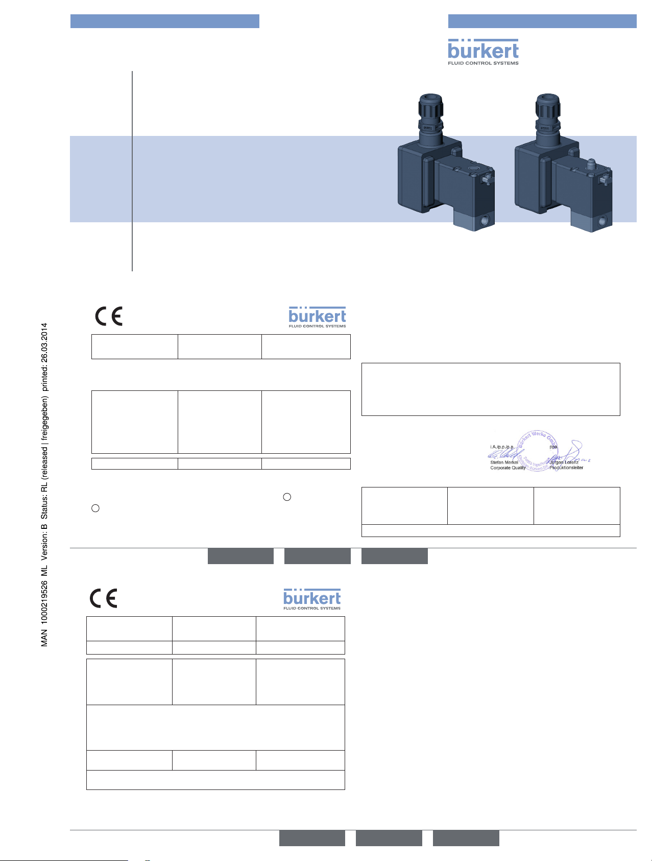
Type 0641, 0642, 0643, 0644,
0651, 0652, 0653, 0654
2/2- or 3/2-way solenoid valve
2/2- oder 3/2-Wege-Magnetventil
Électrovanne 2/2 ou 3/2 voies
2
EG-Konformitäts-
erklärung
EC Declaration
of Conformity
Déclaration
de Conformité CE
Hersteller / Manufacturer / Constructeur : Bürkert Werke GmbH
Christian-Bürkert-Str. 13-17
74653 Ingelfingen, Germany
Hiermit erklären wir,
dass das nachfolgend
aufgeführte Produkt
den Anforderungen der
unten aufgeführten Europäischen Richtlinie(n)
entspricht:
We hereby declare,
that the product listed
below complies with the
below listed European
Directive(s):
Nous déclarons par la
présente que le produit
suivant est conforme aux
directive(s) européenne(s)
mentionnée(s) ci-dessous :
94/9/EG – ATEX 94/9/EC – ATEX 94/9/CE – ATEX
Typ / Type / Type
(Geräteschlüssel / product specification key / clé de produit) :
• 0641, 0642, 0643, 0644, 0651, 0652, 0653, 0654
1
1
Variabler Code / Variable code / Variable Code :
Gilt nur in Verbindung mit / Only valid in combination with / Est pas valable
en lien avec : PD27, PD28
Diese EG-Konformitätserklärung gilt nur
für die Bauteile, die
von Bürkert gefertigt
wurden.
This EC declaration of
conformity is valid only
for the components
which were manufactured by Bürkert.
Cette déclaration de
conformité CE est
valable seulement
pour les parties de
construction qui étaient
fabriquées par Bürkert.
Für die Bewertung
wurden folgende
Normen herangezogen
(wenn anwendbar):
For evaluation of the
conformity, the following
standards were consulted (if applicable):
Pour l‘évaluation de la
conformité, les normes
suivantes ont été utilisées (le cas échéant) :
ATEX: EN 60079-0:2012; EN 60079-7:2007; EN 60079-18:2009
Ingelfingen, 19.03.2014
Die Sicherheits- und Einbauhinweise der mitgelieferten
Produktdokumentation sind zu
beachten.
The instructions for safety and
installation of the enclosed
product documentation have to
be observed.
Les consignes de sécurité et
d‘installation décrites dans la
documentation fournie avec le
produit doivent être respectées.
SAP-Document-No.: 1000219880 Rev.: -
deutschenglish français
3
EG-Konformitäts-
erklärung
EC Declaration
of Conformity
Déclaration
de Conformité CE
- Anhang - - Annex - - Annexe -
94/9/EG – ATEX
Das genannte Produkt
ist bescheinigt durch die
Benannte Stelle:
(bei ATEX Kategorie 1 und 2)
94/9/EC – ATEX
The product is certified
by the Notified Body:
(for ATEX Category 1 and 2)
94/9/CE – ATEX
Le produit est certifié par
l‘organisme notifié :
(pour les produits Atex
catégorie 1 et 2)
Name und Anschrift der Benannten Stelle:/ Name and Address of the notified
body: / Nom et adresse de l‘organisme notifié:
Physikalisch-Technische Bundesanstalt (PTB)
Bundesallee 100
38166 BRAUNSCHWEIG, Germany
EG-Baumusterprüfbescheinigung Nr.:
EC Type Examination
Certificate No.:
Attestation d’examen CE
de type Non.:
PTB 02 ATEX 2094 X
3. Ergänzung vom 7. November 2013
deutsch english
français
Page 2
4
1 OPERATING INSTRUCTIONS
The operating instructions contain important information.
▶ Read the operating instructions carefully and follow the safety instruc-
tions in particular, and also observe the operating conditions.
▶ Operating instructions must be available to each user.
▶ The liability and warranty for the Type 64.- / 65.- are void if the operat-
ing instructions are not followed.
1.1 Symbols
▶ Designates an instruction to prevent risks.
→ designates a procedure which you must carry out.
Warning of injuries:
DANGER!
Imminent danger! Serious or fatal injuries.
WARNING!
Potential danger! Serious or fatal injuries.
CAUTION!
Danger! Minor or moderately severe injuries.
Warns of damage to property:
NOTE!
2 INTENDED USE
Incorrect use of the solenoid valve Type 64.- / 65.- can be dangerous
to people, nearby equipment and the environment.
▶ The device is designed for blocking, dosing, filling and venting neutral
gaseous and liquid media.
▶ Use according to the permitted data, operating conditions and con-
ditions of use specified in the contract documents and operating
instructions.
▶ The device may be used only in conjunction with third-party devices
and components recommended and authorised by Bürkert.
▶ Correct transportation, correct storage and installation and careful use
and maintenance are essential for reliable and problem-free operation.
▶ Use the device only as intended.
2.1 Definition of term
In these operating instructions, the term “device” always refers to the
solenoid valve Type 64.- / 65.-.
2.2 Restrictions
If exporting the system/device, observe any existing restrictions.
english
5
3 BASIC SAFETY INSTRUCTIONS
These safety instructions do not make allowance for any contingencies
and events which may arise during installation, operation and maintenance.
Danger – high pressure!
▶ Before loosening the lines and valves, turn off the pressure and
vent the lines.
Risk of electric shock!
▶ Before reaching into the system, switch off the power supply and
secure to prevent reactivation!
▶ Observe applicable accident prevention and safety regulations for
electrical equipment!
Risk of burns/risk of fire!
During continuous operation the surface of the device may become hot.
▶ Keep the device away from highly flammable substances and media
and do not touch the device with bare hands.
▶ Do not obstruct the heat release required for operation.
2.3 Approvals
The approval mark indicated on the Bürkert labels refers to the Bürkert
products.
2.4 Ex approval
• The Ex approval is only valid if you use the modules and components
authorized by Bürkert as described in these operating instructions.
• You may use the electronic modules only in combination with the
pneumatic valve types released by Bürkert, otherwise the Ex approval
will be void.
• If you make unauthorized changes to the system, the modules or components, the Ex approval will also be void.
english
6
Destruction of the coil by overheating!
▶ Connect the coil electrically only when the body has been installed.
General hazardous situations.
To prevent injury, ensure that:
▶ Do not supply the medium connectors of the system with aggressive
or flammable mediums.
▶ Do not make any internal or external changes. Ensure that the system
cannot be activated unintentionally.
▶ Installation and repair work may be carried out by authorized techni-
cians only and with the appropriate tools.
▶ After an interruption in the power supply or pneumatic supply, ensure
that the process is restarted in a defined or controlled manner.
▶ Do not put any loads on the body.
▶ Observe the general regulations of technology.
3.1 Models with explosion protection
DANGER!
Danger of explosion!
Improper use in the potentially explosive area may result in an explosion.
▶ Follow the specifications in the certificate of conformity.
▶ Follow the specifications in the ATEX instructions.
3.2 Warranty
The warranty is only valid if the device is used as intended in accordance
with the specified application conditions.
3.3 Information on the internet
The operating instructions and data sheets for type 64.- / 65.- can be
found on the internet at:
www.burkert.com
Type 64.- / 65.-
english
Type 0641
Page 3
7
4 SYSTEM DESCRIPTION
4.1 General description
• Type 64.- / 65.- is used for the blocking, dosing, filling and venting of
neutral gaseous and liquid media.
• The valve can be installed individually or in a block on the multiple
manifold (follow the temperature ranges in the ATEX instructions).
5 TECHNICAL DATA
5.1 Conformity
In accordance with the EC Declaration of conformity, Type 64.- / 65.- is
compliant with the EC Directives.
5.2 Standards
The applied standards, which verify conformity with the EC Directives,
can be found on the EC-Type Examination Certificate and / or the EC
Declaration of Conformity.
5.3 Operating conditions
WARNING!
Heat sources and temperature fluctuations may cause malfunctions or leaks!
▶ If the device is used outdoors, do not expose it unprotected to the
weather conditions.
▶ Avoid heat sources which may cause the allowable temperature
range to be exceeded.
5.3.1 Permitted temperature
Ambient temperature: see instruction ATEX
Permitted medium temperature:
Circuit
function
Sealing
material
Medium
temperature
Type /
Types of installation
A FKM / NBR -10 ... +60 °C 64.- Single mounting
-10 ... +45 °C 64.- Block assembly
-10 ... +50 °C 65.- Single mounting
-10 ... +40 °C 65.- Block assembly
english
8
5.3.2 Permitted media
Media neutral gaseous and liquid media, which do not
attack body and sealing materials (see table of
resistance under www.burkert.com)
Check resistance in individual cases
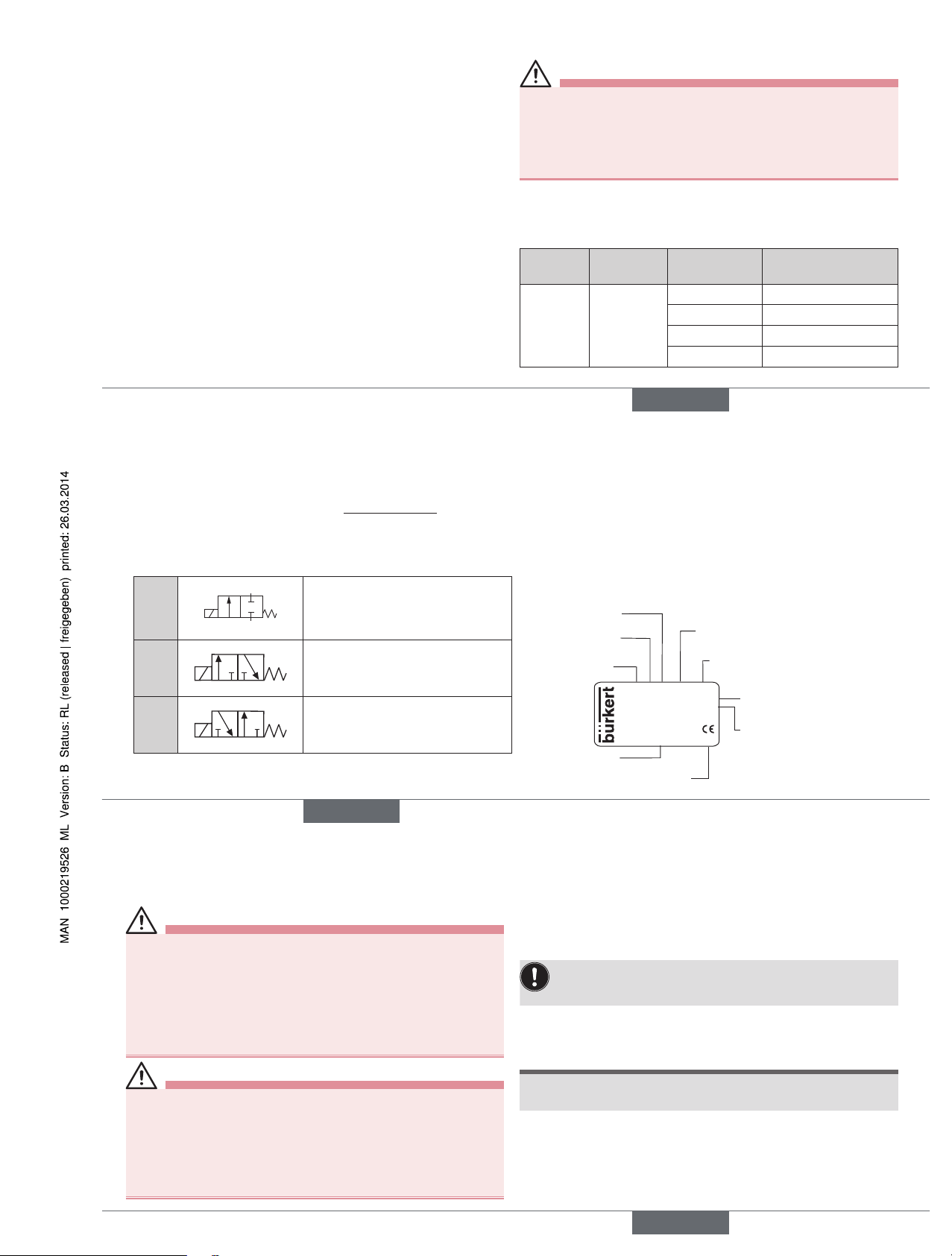
5.4 Fluidic data
Circuit function
A
(NC)
1 (P)
2 (A)
2/2-way valve, normally closed
C
(NC)
2(A)
1(P)
3(R)
3/2-way valve, direct-acting,
output A normally unloaded
D
(NO)
2(B)
1(P)
3(R)
3/2-way valve, direct-acting,
output B normally pressurized
Pressure range see type label
Line connectors G 1/8, G 1/4, NPT 1/8, NPT 1/4, Flange
5.5 Electrical data
Connections Terminal box, permanently installed cable
Operating voltage see type label
Voltage tolerance ± 10 %
Protection class IP65 in accordance with DIN EN 60529 /
IEC 60529
Viscosity 21 mm2/s
5.6 Type label
Typ e
Circuit function
Orifice
Sealing material
Body material
Id. Number
Manufacturer code
Voltage, Frequency,
Power consumption
Connection thread, Operating
pressure
0641 A 3,0 FKM MS
Made in Germany
00050443
W12MN
24V AC/DC 7 W
G 1/4 P
N 0 - 4 bar
english
9
6 INSTALLATION
6.1 Safety instructions
DANGER!
Risk of injury from high pressure in the equipment!
▶ Before loosening the pipes and valves, turn off the pressure and vent
the lines.
Risk of injury due to electrical shock!
▶ Before reaching into the device or the equipment, switch off the power
supply and secure to prevent reactivation.
▶ Observe applicable accident prevention and safety regulations for
electrical equipment.
WARNING!
Risk of injury from improper installation!
▶ Installation may be carried out by authorized technicians only and with
the appropriate tools.
Risk of injury from unintentional activation of the system and an
uncontrolled restart!
▶ Secure system from unintentional activation.
▶ Following assembly, ensure a controlled restart.
6.2 Fluid installation
Installation position: any, actuator preferably upwards.
Procedure:
→ Clean any possible dirt off the pipelines and flange connections.
→ Install a dirt trap to prevent malfunctions (0,2 ... 0,4 mm).
Observe direction of flow:
from 1(P) → 2(A) (circuit function A) / (circuit function C), or
1(P) → 2(B) (circuit function D).
Valve with threaded connection:
→ Use a suitable sealing material.
NOTE!
Caution risk of breakage!
• Do not use the coil as a lever arm.
→ Hold the valve with the appropriate tool on the body and screw into
the pipeline.
english
Type 0641
Page 4
10
Valve with flanged connection:
→ Remove the cover plate.
WARNING!
Danger – escaping medium!
Leaking connections if seals not seated properly, if manifold uneven or if
surface quality of the manifold inadequate.
▶ Make certain the seals included with delivery are properly seated in
the valve.
▶ Ensure that the manifold is even.
▶ Ensure that the surface quality of the manifold is adequate.
→ Insert the seal into the body.
→ Screw the valve onto the manifold
(Tightening torque max. 1.5 Nm).
6.3 Electric installation
WARNING!
Risk of injury due to electrical shock!
▶ Before reaching into the system, switch off the power supply and
secure to prevent reactivation!
▶ Observe applicable accident prevention and safety regulations for
electrical equipment!
If the protective conductor contact between the coil and body is
missing, there is danger of electrical shock!
▶ Always connect protective conductor.
Note the voltage and current type as specified on the type label.
Procedure:
→ Check that the seal is correctly seated.
→ Connect the protective conductor.
english
11
7 MAINTENANCE, TROUBLESHOOTING
7.1 Safety instructions
WARNING!
Risk of injury from improper maintenance!
▶ Maintenance may be carried out by authorized technicians only and
with the appropriate tools!
Risk of injury from unintentional activation of the system and an
uncontrolled restart!
▶ Secure system from unintentional activation.
▶ Following maintenance, ensure a controlled restart.
7.2 Malfunctions
If malfunctions occur, check:
• the line connectors,
• the operating pressure,
• the power supply and valve control.
If the valve still does not switch, please contact your Bürkert Service.
8 DISASSEMBLY
8.1 Safety instructions
DANGER!
Risk of injury from high pressure in the equipment!
▶ Before loosening the pipes and valves, turn off the pressure and
vent the lines.
Risk of injury due to electrical shock!
▶ Before reaching into the device or the equipment, switch off the
power supply and secure to prevent reactivation.
▶ Observe applicable accident prevention and safety regulations for
electrical equipment.
WARNING!
Risk of injury from improper disassembly!
▶ Disassembly may be carried out by authorized technicians only and
with the appropriate tools!
english
12
8.2 Disassembly
Procedure:
→ Turn off the pressure and vent the lines.
→ Switch off the power supply.
Valve with threaded connection:
→ Hold the device with the appropriate tool on the body and screw off
the pipeline.
Valve with flanged connection:
→ Loosen the valve from the manifold.
9 SPARE PARTS
CAUTION!
Risk of injury and/or damage by the use of incorrect parts!
Incorrect accessories and unsuitable spare parts may cause injuries and
damage the device and the surrounding area.
▶ Use only original accessories and original spare parts from Bürkert.
10 TRANSPORT, STORAGE, DISPOSAL
NOTE!
Transport damages!
Inadequately protected equipment may be damaged during transport.
• During transportation protect the device against wet and dirt in
shock-resistant packaging.
• Avoid exceeding or dropping below the allowable storage
temperature.
• Protect electrical interfaces of the coil and the pneumatic connections from damage with protective caps.
Incorrect storage may damage the device.
• Store the device in a dry and dust-free location!
• Storage temperature -40 ... +70 °C.
Damage to the environment caused by device components contaminated with media.
• Dispose of the device and packaging in an environmentally friendly
manner.
• Observe applicable regulations on disposal and the environment.
english
Type 0641
Page 5

Bedienungsanleitung
Manuel d‘utilisation
Operating Instructions
Type 0641, 0642, 0643, 0644,
0651, 0652, 0653, 0654
2/2- or 3/2-way solenoid valve
2/2- oder 3/2-Wege-Magnetventil
Électrovanne 2/2 ou 3/2 voies
2
EG-Konformitäts-
erklärung
EC Declaration
of Conformity
Déclaration
de Conformité CE
Hersteller / Manufacturer / Constructeur : Bürkert Werke GmbH
Christian-Bürkert-Str. 13-17
74653 Ingelfingen, Germany
Hiermit erklären wir,
dass das nachfolgend
aufgeführte Produkt
den Anforderungen der
unten aufgeführten Europäischen Richtlinie(n)
entspricht:
We hereby declare,
that the product listed
below complies with the
below listed European
Directive(s):
Nous déclarons par la
présente que le produit
suivant est conforme aux
directive(s) européenne(s)
mentionnée(s) ci-dessous :
94/9/EG – ATEX 94/9/EC – ATEX 94/9/CE – ATEX
Typ / Type / Type
(Geräteschlüssel / product specification key / clé de produit) :
• 0641, 0642, 0643, 0644, 0651, 0652, 0653, 0654
1
1
Variabler Code / Variable code / Variable Code :
Gilt nur in Verbindung mit / Only valid in combination with / Est pas valable
en lien avec : PD27, PD28
Diese EG-Konformitätserklärung gilt nur
für die Bauteile, die
von Bürkert gefertigt
wurden.
This EC declaration of
conformity is valid only
for the components
which were manufactured by Bürkert.
Cette déclaration de
conformité CE est
valable seulement
pour les parties de
construction qui étaient
fabriquées par Bürkert.
Für die Bewertung
wurden folgende
Normen herangezogen
(wenn anwendbar):
For evaluation of the
conformity, the following
standards were consulted (if applicable):
Pour l‘évaluation de la
conformité, les normes
suivantes ont été utilisées (le cas échéant) :
ATEX: EN 60079-0:2012; EN 60079-7:2007; EN 60079-18:2009
Ingelfingen, 19.03.2014
Die Sicherheits- und Einbauhinweise der mitgelieferten
Produktdokumentation sind zu
beachten.
The instructions for safety and
installation of the enclosed
product documentation have to
be observed.
Les consignes de sécurité et
d‘installation décrites dans la
documentation fournie avec le
produit doivent être respectées.
SAP-Document-No.: 1000219880 Rev.: -
deutschenglish français
3
EG-Konformitäts-
erklärung
EC Declaration
of Conformity
Déclaration
de Conformité CE
- Anhang - - Annex - - Annexe -
94/9/EG – ATEX
Das genannte Produkt
ist bescheinigt durch die
Benannte Stelle:
(bei ATEX Kategorie 1 und 2)
94/9/EC – ATEX
The product is certified
by the Notified Body:
(for ATEX Category 1 and 2)
94/9/CE – ATEX
Le produit est certifié par
l‘organisme notifié :
(pour les produits Atex
catégorie 1 et 2)
Name und Anschrift der Benannten Stelle:/ Name and Address of the notified
body: / Nom et adresse de l‘organisme notifié:
Physikalisch-Technische Bundesanstalt (PTB)
Bundesallee 100
38166 BRAUNSCHWEIG, Germany
EG-Baumusterprüfbescheinigung Nr.:
EC Type Examination
Certificate No.:
Attestation d’examen CE
de type Non.:
PTB 02 ATEX 2094 X
3. Ergänzung vom 7. November 2013
deutsch english
français
Page 6

13
1 DIE BEDIENUNGSANLEITUNG
Die Bedienungsanleitung enthält wichtige Informationen.
▶ Bedienungsanleitung sorgfältig lesen und Hinweise zur Sicherheit
beachten.
▶ Bedienungsanleitung muss jedem Benutzer zur Verfügung stehen.
▶ Haftung und Gewährleistung für Typen 64.-/ 65.- entfällt, wenn die
Anweisungen der Bedienungsanleitung nicht beachtet werden.
1.1 Darstellungsmittel
▶ markiert eine Anweisung zur Gefahrenvermeidung.
→ markiert einen Arbeitsschritt, den Sie ausführen müssen.
Warnung vor Verletzungen:
GEFAHR!
Unmittelbare Gefahr! Schwere oder tödliche Verletzungen.
WARNUNG!
Mögliche Gefahr! Schwere oder tödliche Verletzungen.
VORSICHT!
Gefahr! Leichte oder mittelschwere Verletzungen.
Warnung vor Sachschäden:
HINWEIS!
2 BESTIMMUNGSGEMÄSSER
GEBRAUCH
Bei nicht bestimmungsgemäßem Einsatz des Magnetventils Typ
64.- / 65.- können Gefahren für Personen, Anlagen in der Umgebung
und die Umwelt entstehen.
▶ Das Gerät ist zum Sperren, Dosieren, Füllen und Belüften von neutralen
gasförmigen und flüssigen Medien konzipiert.
▶ Für den Einsatz die in den Vertragsdokumenten und der Bedienungs-
anleitung spezifizierten zulässigen Daten, Betriebs- und Einsatzbedingungen beachten.
▶ Das Gerät nur in Verbindung mit von Bürkert empfohlenen bzw. zuge-
lassenen Fremdgeräten und -komponenten einsetzen.
▶ Voraussetzungen für den sicheren und einwandfreien Betrieb sind
sachgemäßer Transport, sachgemäße Lagerung und Installation sowie
sorgfältige Bedienung und Instandhaltung.
▶ Das Gerät nur bestimmungsgemäß einsetzen.
2.1 Begriffsdefinition
Der verwendete Begriff „Gerät“ steht immer für das Magnetventil des Typs
64.- / 65.-.
deutsch
14
3 GRUNDLEGENDE
SICHERHEITSHINWEISE
Diese Sicherheitshinweise berücksichtigen keine Zufälligkeiten und
Ereignisse, die bei Montage, Betrieb und Wartung auftreten können.
Gefahr durch hohen Druck!
▶ Vor dem Lösen von Leitungen und Ventilen den Druck abschalten
und Leitungen entleeren.
Gefahr durch elektrische Spannung!
▶ Vor Eingriffen in das Gerät oder die Anlage Spannung abschalten
und vor Wiedereinschalten sichern.
▶ Die geltenden Unfallverhütungs- und Sicherheitsbestimmungen für
elektrische Geräte beachten.
Verbrennungsgefahr/Brandgefahr!
Bei Dauerbetrieb kann eine heiße Geräteoberfläche entstehen.
▶ Das Gerät von leicht brennbaren Stoffen und Medien fernhalten und
nicht mit bloßen Händen berühren.
▶ Die für den Betrieb notwendige Wärmeabfuhr nicht behindern.
2.2 Beschränkungen
Beachten Sie bei der Ausfuhr des Systems/Geräts gegebenenfalls
bestehende Beschränkungen.
2.3 Zulassungen
Die auf den Bürkert Typschildern aufgebrachte Zulassungskennzeichnung
bezieht sich auf die Bürkert Produkte.
2.4 Ex-Zulassung
• Ex-Zulassung ist nur gültig, wenn Sie die von Bürkert zugelassenen
Module und Komponenten so verwenden, wie es in dieser Bedienungsanleitung beschrieben ist.
• Die Elektronikmodule dürfen nur in Kombination mit den von Bürkert
freigegebenen Pneumatikventiltypen eingesetzt werden.
• Keine unzulässigen Veränderungen am System, den Modulen oder
Komponenten vornehmen.
deutsch
15
Zerstörung der Spule durch Überhitzung!
▶ Spule nur mit montiertem Gehäuse elektrisch anschließen.
Allgemeine Gefahrensituationen.
Zum Schutz vor Verletzungen ist zu beachten:
▶ Keine aggressiven oder brennbaren Medien einspeisen.
▶ Keine inneren oder äußeren Veränderungen vornehmen. Anlage/Gerät
vor unbeabsichtigter Betätigung sichern.
▶ Installations- und Instandhaltungsarbeiten dürfen nur von autorisiertem
Fachpersonal mit geeignetem Werkzeug ausgeführt werden.
▶ Nach einer Unterbrechung der elektrischen oder fluidischen
Versorgung ist ein definierter oder kontrollierter Wiederanlauf des
Prozesses zu gewährleisten.
▶ Gehäuse nicht mechanisch belasten.
▶ Die allgemeinen Regeln der Technik einhalten.
3.1 Ausführungen mit Explosionsschutz
GEFAHR!
Explosionsgefahr!
Bei unsachgemäßem Einsatz im explosionsgefährdeten Bereich
besteht Explosionsgefahr.
▶ Beachten Sie die Angaben der Konformitätsbescheinigung.
▶ Beachten Sie die Angaben der ATEX-Anleitung.
3.2 Gewährleistung
Voraussetzung für die Gewährleistung ist der bestimmungsgemäße Gebrauch des Geräts unter Beachtung der spezifizierten
Einsatzbedingungen.
3.3 Informationen im Internet
Bedienungsanleitungen und Datenblätter zum Typ 64.- / 65.- finden Sie
im Internet unter:
www.buerkert.de
Typ 64.- / 65.-
deutsch
Typ 0641
Page 7

16
4 SYSTEMBESCHREIBUNG
4.1 Allgemeine Beschreibung
• Typ 64.- / 65.- wird zum Sperren, Dosieren, Füllen und Belüften von
neutralen gasförmigen und flüssigen Medien verwendet.
• Das Ventil kann einzeln oder im Block auf Mehrfachanschlussplatte
montiert werden (Temperaturangaben der ATEX-Anleitung beachten).
5 TECHNISCHE DATEN
5.1 Konformität
Das Magnetventil Typ 64.- / 65.- ist konform zu den EG-Richtlinien
entsprechend der EG-Konformitätserklärung.
5.2 Normen
Die angewandten Normen, mit denen die Konformität mit den EG-Richtlinien nachgewiesen wird, sind in der EG-Baumusterprüfbescheinigung
und/oder der EG-Konformitätserklärung nachzulesen.
5.3 Betriebsbedingungen
WARNUNG!
Wärmequellen oder Temperaturschwankungen können Fehlfunktionen oder Undichtheiten bewirken!
▶ Bei Einsatz im Außenbereich das Gerät nicht ungeschützt den Wit-
terungsverhältnissen aussetzen.
▶ Wärmequellen vermeiden, die zur Überschreitung des zulässigen
Temperaturbereichs führen können.
5.3.1 Zulässige Temperatur
Umgebungstemperatur: siehe ATEX-Anleitung
Zulässigen Mediumstemperatur:
Wirkungs-
weise
Dichtungs-
material
Mediums-
temperatur
Typ /
Montageart
A FKM / NBR -10 ... +60 °C 64.- Einzelmontage
-10 ... +45 °C 64.- Blockmontage
-10 ... +50 °C 65.- Einzelmontage
-10 ... +40 °C 65.- Blockmontage
deutsch
17
5.3.2 Zulässige Medien
Medien neutrale gasförmige und flüssige Medien, die
Gehäuse/Dichtwerkstoffe nicht angreifen (siehe
Beständigkeitstabelle unter www.buerkert.de)
Beständigkeit im Einzelfall prüfen
5.4 Fluidische Daten
Wirkungsweisen
A
(NC)
1 (P)
2 (A)
2/2-Wege-Ventil,
stromlos geschlossen
C
(NC)
2(A)
1(P)
3(R)
3/2-Wege-Ventil, direktwirkend,
stromlos Ausgang A entlastet
D
(NO)
2(B)
1(P)
3(R)
3/2 Wege-Ventil, direktwirkend,
stromlos Ausgang B druckbeaufschlagt
Druckbereich siehe Typschild
Leitungsanschluss G 1/8, G 1/4, NPT 1/8, NPT 1/4, Flansch
5.5 Elektrische Daten
Anschlüsse Klemmenkasten, fest eingebautes Kabel
Betriebsspannung siehe Typschild
Spannungstoleranz ± 10 %
Schutzart IP65 nach DIN EN 60529 / IEC 60529
Viskosität 21 mm2/s
5.6 Typschild
Typ
Wirkungsweise
Nennweite
Dichtwerkstoff
Gehäusewerkstoff
Identnummer
Hersteller-Code
Spannung, Frequenz, Leistung
Anschlussart, Betriebsdruck
0641 A 3,0 FKM MS
Made in Germany
00050443
W12MN
24V AC/DC 7 W
G 1/4 P
N 0 - 4 bar
deutsch
18
6 INSTALLATION
6.1 Sicherheitshinweise
GEFAHR!
Verletzungsgefahr durch hohen Druck in der Anlage!
▶ Vor dem Lösen von Leitungen oder Ventilen den Druck abschalten
und Leitungen entleeren.
Verletzungsgefahr durch Stromschlag!
▶ Vor Eingriffen in das Gerät oder die Anlage Spannung abschalten
und vor Wiedereinschalten sichern!
▶ Die geltenden Unfallverhütungs- und Sicherheitsbestimmungen für
elektrische Geräte beachten!
WARNUNG!
Verletzungsgefahr bei unsachgemäßer Installation!
▶ Die Installation darf nur autorisiertes Fachpersonal mit geeignetem
Werkzeug durchführen!
Verletzungsgefahr durch ungewolltes Einschalten der Anlage und
unkontrollierten Wiederanlauf!
▶ Anlage vor unbeabsichtigtem Betätigen sichern.
▶ Nach der Installation einen kontrollierten Wiederanlauf gewährleisten.
6.2 Fluidische Installation
Einbaulage: beliebig, vorzugsweise Antrieb oben.
Vorgehensweise:
→ Rohrleitungen und Flanschanschlüsse säubern.
→ Schmutzfilter am Ventileingang einbauen (0,2 ... 0,4 mm).
Durchflussrichtung beachten:
von 1(P) → 2(A) (Wirkungsweise A) / (Wirkungsweise C), oder
1(P) → 2(B) (Wirkungsweise D).
Ventil mit Gewindeanschluss:
→ Geeignetes Dichtungsmaterial verwenden.
HINWEIS!
Vorsicht Bruchgefahr!
• Spule nicht als Hebelarm benutzen.
→ Ventil mit passendem Werkzeug am Gehäuse festhalten und in die
Rohrleitung einschrauben.
deutsch
Typ 0641
Page 8

19
Ventil mit Flanschanschluss:
→ Verschlussplatte entfernen.
WARNUNG!
Gefahr durch Mediumsaustritt!
Undichte Anschlüsse bei ungenauem Sitz der Dichtungen, bei
unebener Anschlussplatte oder unzureichender Oberflächengüte der
Anschlussplatte.
▶ Bei mitgelieferten Dichtungen auf den richtigen Sitz im Ventil achten.
▶ Auf die Ebenheit und ausreichende Oberflächengüte der Anschluss-
platte achten.
→ Dichtung in Gehäuse einlegen.
→ Ventil auf Anschlussplatte schrauben
(Anziehdrehmoment max. 1,5 Nm).
6.3 Elektrische Installation
WARNUNG!
Verletzungsgefahr durch Stromschlag!
▶ Vor Eingriffen in das Gerät oder die Anlage Spannung abschalten
und vor Wiedereinschalten sichern!
▶ Die geltenden Unfallverhütungs- und Sicherheitsbestimmungen für
elektrische Geräte beachten!
Bei fehlendem Schutzleiterkontakt zwischen Spule und Gehäuse
besteht die Gefahr des Stromschlags!
▶ Schutzleiter immer anschließen.
Spannung und Stromart laut Typschild beachten.
Vorgehensweise:
→ Korrekten Sitz der Dichtung überprüfen.
→ Schutzleiter anschließen.
deutsch
20
7 WARTUNG, FEHLERBEHEBUNG
7.1 Sicherheitshinweise
WARNUNG!
Verletzungsgefahr bei unsachgemäßen Wartungsarbeiten!
▶ Die Wartung darf nur autorisiertes Fachpersonal mit geeignetem
Werkzeug durchführen!
Verletzungsgefahr durch ungewolltes Einschalten der Anlage und
unkontrollierten Wiederanlauf!
▶ Anlage vor unbeabsichtigtem Betätigen sichern.
▶ Nach der Wartung einen kontrollierten Wiederanlauf gewährleisten.
7.2 Störungen
Bei Störungen überprüfen:
• Leitungsanschlüsse,
• Betriebsdruck,
• Betriebsspannung und Ventilansteuerung.
Falls das Ventil dennoch nicht schaltet, wenden Sie sich bitte an Ihre
Bürkert-Vetriebsniederlassung.
8 AUSSERBETRIEBNAHME
8.1 Sicherheitshinweise
GEFAHR!
Verletzungsgefahr durch hohen Druck in der Anlage!
▶ Vor dem Lösen von Leitungen oder Ventilen den Druck abschalten
und Leitungen entleeren.
Verletzungsgefahr durch Stromschlag!
▶ Vor Eingriffen in das Gerät oder die Anlage Spannung abschalten
und vor Wiedereinschalten sichern!
▶ Die geltenden Unfallverhütungs- und Sicherheitsbestimmungen für
elektrische Geräte beachten!
WARNUNG!
Verletzungsgefahr bei unsachgemäßer Demontage!
▶ Die Demontage darf nur autorisiertes Fachpersonal mit geeignetem
Werkzeug durchführen!
deutsch
21
8.2 Demontage
Vorgehensweise:
→ Druck abschalten und Leitungen entleeren.
→ Elektrische Spannung abschalten.
Ventil mit Gewindeanschluss:
→ Ventil mit passendem Werkzeug am Gehäuse festhalten und von
der Rohrleitung abschrauben.
Ventil mit Flanschanschluss:
→ Ventil von der Anschlussplatte demontieren.
9 ERSATZTEILE
VORSICHT!
Verletzungsgefahr, Sachschäden durch falsche Teile!
Falsches Zubehör und ungeeignete Ersatzteile können Verletzungen
und Schäden am Gerät und dessen Umgebung verursachen.
▶ Nur Originalzubehör sowie Originalersatzteile der Firma Bürkert
verwenden.
10 TRANSPORT, LAGERUNG,
ENTSORGUNG
HINWEIS!
Transportschäden!
Unzureichend geschützte Geräte können durch den Transport
beschädigt werden.
• Gerät vor Nässe und Schmutz geschützt in einer stoßfesten Verpackung transportieren.
• Eine Über- bzw. Unterschreitung der zulässigen Lagertemperatur
vermeiden.
• Elektrische Schnittstellen der Spule mit Schutzkappen vor Beschädigungen schützen.
Falsche Lagerung kann Schäden am Gerät verursachen.
• Gerät trocken und staubfrei lagern!
• Lagertemperatur: –40 ... +70 °C.
Umweltschäden durch von Medien kontaminierte Geräteteile.
• Gerät und Verpackung umweltgerecht entsorgen.
• Geltende Entsorgungsvorschriften und Umweltbestimmungen
einhalten.
deutsch
Typ 0641
Page 9

Bedienungsanleitung
Manuel d‘utilisation
Operating Instructions
Type 0641, 0642, 0643, 0644,
0651, 0652, 0653, 0654
2/2- or 3/2-way solenoid valve
2/2- oder 3/2-Wege-Magnetventil
Électrovanne 2/2 ou 3/2 voies
2
EG-Konformitäts-
erklärung
EC Declaration
of Conformity
Déclaration
de Conformité CE
Hersteller / Manufacturer / Constructeur : Bürkert Werke GmbH
Christian-Bürkert-Str. 13-17
74653 Ingelfingen, Germany
Hiermit erklären wir,
dass das nachfolgend
aufgeführte Produkt
den Anforderungen der
unten aufgeführten Europäischen Richtlinie(n)
entspricht:
We hereby declare,
that the product listed
below complies with the
below listed European
Directive(s):
Nous déclarons par la
présente que le produit
suivant est conforme aux
directive(s) européenne(s)
mentionnée(s) ci-dessous :
94/9/EG – ATEX 94/9/EC – ATEX 94/9/CE – ATEX
Typ / Type / Type
(Geräteschlüssel / product specification key / clé de produit) :
• 0641, 0642, 0643, 0644, 0651, 0652, 0653, 0654
1
1
Variabler Code / Variable code / Variable Code :
Gilt nur in Verbindung mit / Only valid in combination with / Est pas valable
en lien avec : PD27, PD28
Diese EG-Konformitätserklärung gilt nur
für die Bauteile, die
von Bürkert gefertigt
wurden.
This EC declaration of
conformity is valid only
for the components
which were manufactured by Bürkert.
Cette déclaration de
conformité CE est
valable seulement
pour les parties de
construction qui étaient
fabriquées par Bürkert.
Für die Bewertung
wurden folgende
Normen herangezogen
(wenn anwendbar):
For evaluation of the
conformity, the following
standards were consulted (if applicable):
Pour l‘évaluation de la
conformité, les normes
suivantes ont été utilisées (le cas échéant) :
ATEX: EN 60079-0:2012; EN 60079-7:2007; EN 60079-18:2009
Ingelfingen, 19.03.2014
Die Sicherheits- und Einbauhinweise der mitgelieferten
Produktdokumentation sind zu
beachten.
The instructions for safety and
installation of the enclosed
product documentation have to
be observed.
Les consignes de sécurité et
d‘installation décrites dans la
documentation fournie avec le
produit doivent être respectées.
SAP-Document-No.: 1000219880 Rev.: -
deutschenglish français
3
EG-Konformitäts-
erklärung
EC Declaration
of Conformity
Déclaration
de Conformité CE
- Anhang - - Annex - - Annexe -
94/9/EG – ATEX
Das genannte Produkt
ist bescheinigt durch die
Benannte Stelle:
(bei ATEX Kategorie 1 und 2)
94/9/EC – ATEX
The product is certified
by the Notified Body:
(for ATEX Category 1 and 2)
94/9/CE – ATEX
Le produit est certifié par
l‘organisme notifié :
(pour les produits Atex
catégorie 1 et 2)
Name und Anschrift der Benannten Stelle:/ Name and Address of the notified
body: / Nom et adresse de l‘organisme notifié:
Physikalisch-Technische Bundesanstalt (PTB)
Bundesallee 100
38166 BRAUNSCHWEIG, Germany
EG-Baumusterprüfbescheinigung Nr.:
EC Type Examination
Certificate No.:
Attestation d’examen CE
de type Non.:
PTB 02 ATEX 2094 X
3. Ergänzung vom 7. November 2013
deutsch english
français
Page 10

22
1 LE MANUEL D’UTILISATION
Manuel d’utilisation contiennent des informations importantes.
▶ Lire attentivement ce manuel d’utilisation et respecter les consignes
de sécurité.
▶ Le manuel d’utilisation doit être à disposition de chaque utilisateur.
▶ Nous déclinons toute responsabilité et n’accordons aucune garantie
légale pour l’appareil type 64.- / 65.- en cas de non-respect des
instructions figurant dans ce manuel d’utilisation.
1.1 Symboles
▶ Identifie une instruction visant à éviter un danger.
→ identifie une opération que vous effectuer.
Mise en garde contre les blessures :
DANGER !
Danger imminent ! Les blessures graves ou mortelles.
AVERTISSEMENT !
Danger possible ! Les blessures graves ou mortelles.
ATTENTION !
Danger ! Les blessures légères ou moyennement graves.
Met en garde contre des dommages matériels :
REMARQUE !
2 UTILISATION CONFORME
L’utilisation non conforme de l’électrovanne, type 64.- / 65.- peut
présenter des dangers pour les personnes, les installations proches
et l’environnement.
▶ L’appareil est conçu pour couper, doser, remplir et aérer les fluides
neutres gazeux et liquides.
▶ Lors de l’utilisation, il convient de respecter les données et conditions
d’utilisation et d’exploitation admissibles spécifiées dans les instructions de service et dans les documents contractuels.
▶ L’appareil peut être utilisé uniquement en association avec les appareils
et composants étrangers recommandés et homologués par Bürkert.
▶ Les conditions pour l’utilisation sûre et parfaite sont un transport,
un stockage et une installation dans les règles ainsi qu’une parfaite
utilisation et maintenance.
▶ Veillez à ce que l’utilisation de l’appareil soit toujours conforme.
2.1 Définition du terme
Le terme « appareil» utilisé dans ce manuel désigne toujours l’électrovanne type 64.- / 65.-.
2.2 Limitations
Lors de l’exportation du système/de l’appareil, veuillez respecter les limitations éventuelles existantes.
français
23
3 CONSIGNES DE SÉCURITÉ
FONDAMENTALES
Ces consignes de sécurité ne tiennent pas compte des hasards et des
événements pouvant survenir lors du montage, de l’exploitation et de
l’entretien.
Danger avec haute pression.
▶ Avant de desserrer les tuyauteries et les vannes, coupez la pression
et purgez les conduites.
Danger présenté par la tension électrique.
▶ Avant d’intervenir dans l’appareil ou l’installation, coupez la tension et
empêchez toute remise sous tension par inadvertance.
▶ Veuillez respecter les réglementations en vigueur pour les appareils
électriques en matière de prévention des accidents ainsi qu’en matière
de sécurité.
Risque de brûlures et d’incendies.
La surface de l’appareil peut devenir brûlante en cas de fonctionnement continu.
▶ Tenez les substances et les fluides facilement inflammables à l’écart
de l’appareil et ne touchez pas ce dernier à mains nues.
▶ Ne pas gêner l’évacuation de la chaleur nécessaire au fonctionnement.
2.3 Homologations
Le marquage d’homologation apposé sur les plaques signalétiques
Bürkert se rapporte aux produits Bürkert.
2.4 Homologation Ex
• L’homologation Ex n’est valable que si vous utilisez les modules et
composants homologués par Bürkert laquelle est décrit dans ces
instructions de service.
• Les modules électroniques peuvent être utilisés uniquement avec les
types de vannes pneumatiques autorisés par Bürkert, sinon l’homologation Ex devient caduque.
• L’homologation Ex devient également caduque si vous apportez des
modifications non autorisées, aux modules ou aux composants.
français
24
Destruction de la bobine par surchauffe.
▶ Effectuer le raccordement électrique de la bobine uniquement lorsque
le corps est monté.
Situations dangereuses d’ordre général.
Pour prévenir les blessures, respectez ce qui suit :
▶ N’alimentez pas les raccords du système en fluides agressifs ou
inflammables.
▶ N’apportez pas de modifications à l’extérieur et l’intérieur de l’appareil.
L’installation ne peut pas être actionnée par inadvertance.
▶ Les travaux d’installation et de maintenance doivent être effectués
uniquement par des techniciens qualifiés et habilités disposant de
l’outillage approprié.
▶ Après une interruption de l’alimentation électrique ou pneumatique,
un redémarrage défini ou contrôlé du processus doit être garanti.
▶ Ne soumettez pas le corps à des contraintes mécaniques.
▶ Respecter les règles générales de la technique.
3.1 Versions avec protection contre les
explosions
DANGER!
Risque d’explosion.
Il y a risque d’explosion en cas d’utilisation non conforme dans des
zones présentant des risques d’explosion.
▶ Respectez également les indications reprises dans le certificat de
conformité.
▶ Respecter également les indications des instructions ATEX.
3.2 Garantie légale
La condition pour bénéficier de la garantie légale est l’utilisation conforme
des appareils dans le respect des conditions d’utilisation spécifiées.
3.3 Informations sur Internet
Vous trouverez sur Internet les instructions de service et fiches techniques
relatives au type :
www.buerkert.fr
Type 64.- / 65.-
français
Type 0641
Page 11

25
4 DESCRIPTION DU SYSTÈME
4.1 Description générale
• Le type 64.- / 65.- est utilisé pour couper, doser, remplir et aérer les
fluides neutres gazeux et liquides.
• La vanne peut être montée seule ou dans un bloc sur des embases
multiples (respecter les indications de température des instructions
ATEX).
5 CARACTÉRISTIQUES TECHNIQUES
5.1 Conformité
Le type 64.- / 65.- est conforme aux directives CE sur la base de la
déclaration de conformité CE.
5.2 Normes
Les normes appliquées justifiant la conformité aux directives CE
peuvent être consultées dans le certificat d’essai de modèle type CE et
/ ou la déclaration de Conformité CE.
5.3 Conditions d’exploitation
AVERTISSEMENT !
Les sources de chaleur et les variations de température
peuvent être à l‘origine de dysfonctionnements ou de fuites.
▶ Lorsqu‘il est utilisé à l‘extérieur, n‘exposez pas l‘appareil aux intem-
péries sans aucune protection.
▶ Évitez les sources de chaleur susceptibles d’entraîner un dépasse-
ment de la plage de température admissible.
5.3.1 Température admissible
Température ambiante : voir les instructions ATEX
Température admissible du fluide :
Fonction Matériau
du joint
Température
du fluide
Type /
Type de montage
A FKM / NBR -10 ... +60 °C 64.- Montage isolé
-10 ... +45 °C 64.- Montage en block
-10 ... +50 °C 65.- Montage isolé
-10 ... +40 °C 65.- Montage en block
français
26
5.3.2 Fluides admissibles
Fluides fluides neutres gazeux et liquides, qui n’at-
taquent pas le corps et les matériaux du joint
(voir tableau de résistance www.buerkert.fr)
Contrôler la résistance au cas par cas
5.4 Données fluidiques
Fonction
A
(NC)
1 (P)
2 (A)
Vanne 2/2 voies, normalement fermée
C
(NC)
2(A)
1(P)
3(R)
Vanne à 3/2 voies, à action directe,
sortie A normalement fermée
D
(NO)
2(B)
1(P)
3(R)
Vanne à 3/2 voies, à action directe,
sortie B normalement ouverte
Plage de pression voir plaque signalétique
Raccords de conduite G 1/8, G 1/4, NPT 1/8, NPT 1/4, Bride
5.5 Caractéristiques électriques
Raccordements Boîte de bornes, câbles installé de façon
permanente
Alimentation en tension voir plaque signalétique
Tolérance de tension ± 10 %
Type de protection IP65 selon DIN EN 60529 / IEC 60529
Viscosité 21 mm2/s
5.6 Plaque signalétique
Typ e
Fonction
Diamètre
nominal
Matériau du joint
Matériau du corps
N° d’identification
Code fabricant
Tension, Fréquence,
Puissance
Raccordement, Pression de
service
0641 A 3,0 FKM MS
Made in Germany
00050443
W12MN
24V AC/DC 7 W
G 1/4 P
N 0 - 4 bar
français
27
6 INSTALLATION
6.1 Consignes de sécurité
DANGER !
Risque de blessures avec présence de haute pression dans
l’installation.
▶ Avant de desserrer les tuyauteries et les vannes, coupez la pression
et purgez les conduites.
Risque de choc électrique.
▶ Avant d’intervenir dans l’appareil ou l’installation, coupez la tension et
empêchez toute remise sous tension par inadvertance.
▶ Veuillez respecter les réglementations en vigueur pour les appareils
électriques en matière de prévention des accidents ainsi qu’en matière
de sécurité.
AVERTISSEMENT !
Risque de blessures pour montage non conforme.
▶ Le montage doit être effectué uniquement par un personnel qualifié
et habilité disposant de l’outillage approprié.
Risque de blessures dû à la mise en marche involontaire de
l’installation et le redémarrage non contrôlé.
▶ Empêchez tout actionnement involontaire de l’installation.
▶ Garantissez un redémarrage contrôlé après le montage.
6.2 Installation fluide
Position de montage : au choix, de préférence avec l’actionneur vers le
haut.
Procédure :
→ Nettoyer la tuyauterie et les raccordements à bride.
→ Monter un filtre à impuretés avant l’entrée de la vanne
(0,2 ... 0,4 mm).
Respectez le sens du débit:
de 1(P) → 2(A) (Fonction A) / (Fonction C), ou
1(P) → 2(B) (Fonction D).
Vanne avec raccord fileté :
→ Utilisez d’un matériau du joint approprié.
REMARQUE !
Attention risque de rupture !
• La bobine ne doit pas être utilisée comme levier.
→ Maintenez le vanne sur le corps à l’aide d’un outil approprié et
vissez-le dans la tuyauterie.
français
Type 0641
Page 12

28
Vanne avec raccord à bride :
→ Enlevez la plaque de fermeture.
AVERTISSEMENT !
Danger dû à la sortie de fluide.
Raccords non étanches dus à une mauvaise position des joints, une plaque
de raccordement non plane ou d’une qualité de surface insuffisante.
▶ Veillez au positionnement correct des joints fournis dans la vanne.
▶ Veillez à la planéité et à une qualité de surface suffisante de la plaque
de raccordement.
→ Placez le joint dans le corps.
→ Vissez le vanne sur l’embase
(couple de serrage max. 1,5 Nm).
6.3 Installation électrique
AVERTISSEMENT !
Risque de choc électrique.
▶ Avant d’intervenir dans le système, coupez la tension et empêchez
toute remise sous tension par inadvertance.
▶ Veuillez respecter les réglementations en vigueur pour les appareils
électriques en matière de prévention des accidents ainsi qu’en
matière de sécurité.
Il y a risque de choc électrique en l’absence d’un contact du
conducteur de protection entre la bobine et le corps
▶ Raccordez toujours le conducteur de protection.
Respectez la tension et le type de courant selon la plaque
signalétique.
Procédure :
→ Contrôler le bon positionnement du joint.
→ Raccordez le conducteur de protection.
français
29
7 MAINTENANCE, DÉPANNAGE
7.1 Consignes de sécurité
AVERTISSEMENT !
Risque de blessures dû à des travaux de maintenance non
conformes.
▶ La maintenance doit être effectué uniquement par un personnel
qualifié et habilité disposant de l’outillage approprié.
Risque de blessures dû à la mise en marche involontaire de l’installation et le redémarrage non contrôlé.
▶ Empêchez tout actionnement involontaire de l’installation.
▶ Garantissez un redémarrage contrôlé après la maintenance.
7.2 Pannes
En présence de pannes, vérifiez :
• les raccords de conduite,
• la pression de service,
• l’alimentation en tension et la commande de la vanne.
Si malgré tout la vanne ne fonctionne pas, veuillez contacter votre
service après-vente Bürkert.
8 DÉMONTAGE
8.1 Consignes de sécurité
DANGER !
Risque de blessures avec présence de haute pression dans
l’installation.
▶ Avant de desserrer les tuyauteries et les vannes, coupez la pression
et purgez les conduites.
Risque de choc électrique.
▶ Avant d’intervenir dans l’appareil ou l’installation, coupez la tension et
empêchez toute remise sous tension par inadvertance.
▶ Veuillez respecter les réglementations en vigueur pour les appareils
électriques en matière de prévention des accidents ainsi qu’en matière
de sécurité.
AVERTISSEMENT !
Risque de blessures dû à un démontage non conforme.
▶ Le démontage doit être effectué uniquement par un personnel
qualifié et habilité disposant de l’outillage approprié.
français
30
8.2 Démontage
Procédure :
→ Coupez la pression et videz les conduits.
→ Coupez la tension.
Vanne avec raccord fileté :
→ Maintenez le vanne sur le corps à l’aide d’un outil approprié et
desserrez de la tuyauterie.
Vanne avec raccord à bride :
→ Desserrez le vanne de l’embase.
9 PIÈCES DE RECHANGE
ATTENTION !
Risque de blessures, de dommages matériels dus à de mauvaises
pièces.
De mauvais accessoires ou des pièces de rechange inadaptées
peuvent provoquer des blessures et endommager l’appareil ou son
environnement.
▶ Utilisez uniquement des accessoires ainsi que des pièces de
rechange d’origine de la société Bürkert.
10 TRANSPORT, STOCKAGE,
ÉLIMINATION
REMARQUE !
Dommages dus au transport.
Les appareils insuffisamment protégés peuvent être endommagés
pendant le transport.
• Transportez l’appareil à l’abri de l’humidité et des impuretés et dans
un emballage résistant aux chocs.
• Évitez le dépassement vers le haut ou le bas de la température de
stockage admissible.
• Protéger les interfaces électriques de la bobine et les raccordements
pneumatiques des détériorations à l’aide des capuchons de protection.
Un mauvais stockage peut endommager l’appareil.
• Stockez l’appareil au sec et à l’abri des poussières !
• Température de stockage : -40 … +70 °C.
Dommages à l’environnement causés par des pièces d’appareil
contaminées par des fluides.
• Éliminez l’appareil et l’emballage dans le respect de l’environnement.
• Respectez les prescriptions en matière d’élimination des déchets et
de protection de l’environnement en vigueur.
français
Type 0641
Page 13

www.burkert.com
International address
www.burkert.com
Manuals and data sheets on the Internet: www.burkert.com
Bedienungsanleitungen und Datenblätter im Internet: www.buerkert.de
Instructions de service et fiches techniques sur Internet : www.buerkert.fr
© Bürker t Werke GmbH , 2014
Operating Instr uctions 1403/02_EU-ML_00810384 / Original DE
Bürkert Fluid Control Systems
Sales Center
Christian-Bürkert-Str. 13-17
D-74653 Ingelfingen
Tel. + 49 (0) 7940 - 10 91 111
Fax + 49 (0) 7940 - 10 91 448
E-mail: info@de.buerkert.com
 Loading...