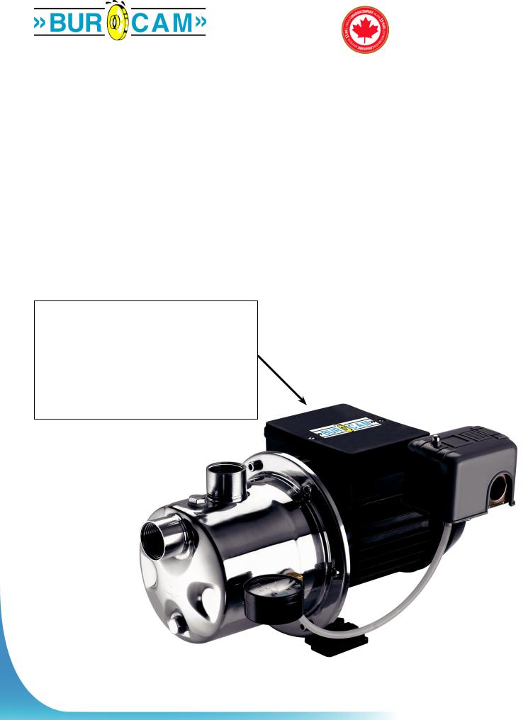
Burcam SW STAINLESS STEEL JET PUMP 3/4HP 115/230V User Manual

www.burcam.com
2190 Dagenais Blvd.West |
TEL: 514.337.4415 |
LAVAL (QUEBEC) |
FAX: 514.337.4029 |
CANADA |
|
H7L 5X9 |
info@burcam.com |
|
|
INSTALLATION INSTRUCTIONS
MODEL
506518SS
AND BY-PRODUCTS LIKE
Your pump has been carefully packaged at
the factory to prevent damage during shipping.
However, occasional damage may occur due
to rough handling. Carefully inspect your pump for damages that could cause failures. Report any damage to your carrier or your point of
purchase.
Factory set voltage 115 V
Connecting volatge changing:
Before changing the voltage connection:
A)Ensure the power to the pump is disconnected.
B)Open motor junction box cover.
C)Please select the up knob position for 115 V or down knob position for 230 V.
D)Connect to appropriate power source.
E)Close motor junction box.
506537SS 506547SS 506538SS 506548SS, 506541SS ETC.
JET PUMP
Please read these instructions carefully.
Failure to comply to instructions and designed operation of this system, may void the warranty.
© 2010 BURCAM Printed in Canada 506516

SAFETY INSTRUCTIONS:
This fine pump that you have just purchased is designed from the
workmanship. Before installation and operation, we recommend the following procedures:
ACHECK WITH YOUR LOCAL ELECTRICAL AND PLUMBING CODES TO ENSURE YOU COMPLY WITH THE REGULATIONS. THESE CODES HAVE BEEN DESIGNED WITH YOUR SAFETY IN MIND. BE SURE YOU COMPLY WITH THEM.
BWE RECOMMEND THAT A SEPARATE CIRCUIT BE LEAD FROM THE HOME ELECTRICAL DISTRIBUTION PANEL PROPERLY PROTECTED WITH A FUSE OR A CIRCUIT BREAKER. THE MOTOR HAVE TO BE SECURELY PLUGGED INTO A PROPER ‘GFCI’ ELECTRICAL OUTLET. CONSULT A LICENSED ELECTRICIAN FOR ALL WIRING.
CTHE GROUND TERMINAL ON THE THREE PRONG PLUGS SHOULD NEVER BE REMOVED. THEY ARE SUPPLIED AND DESIGNED FOR YOUR PROTECTION.
DNEVER MAKE ADJUSTMENTS TO ANY ELECTRICAL APPLIANCE OR PRODUCT WITH THE POWER CONNECTED. DO NOT ONLY UNSCREW THE FUSE OR TRIP THE BREAKER, REMOVE THE POWER PLUG FROM THE RECEPTACLE.
Monthly Mandatory check-up:
1.Inspect the pump for any obvious condition that necessitates cleaning, correction, adjustement or repair.
2.Clear the surrounding of any paper, leaves or other debris.
3.Assure that the pump is secure for proper operation.
4.Assure that there is adequate clearance from any combustible materials or stucture. Stored materials must be kept away from the pump. Shelves or cabinet structures must not be in close proximity over the pump.
5.Assure that the motor is securely plugged into a proper GFCI electrical outlet.
6.Test the GFCI outlet by pressing its test switch. This should prove that the outlet is energized and will trip off to protect against a ground fault. Be sure to reset the GFCI by pressing its reset switch.
7.Observe that the plumbing can carry the water safely into the residence.
MATERIAL REQUIRED FOR DRILLED WELL APPLICATION (indoor use only)
Shallow well pump installation
Desired length of polyethylene 1” pipe, 100 PSI, CSA or UL approved, to link up from pumping level to pump.
1 1” foot valve (750756 or 750752P).
1 well seal, as per well casing diameter (750929 6” x 1”).
1 1” well seal elbow (750860).
2 1” male adaptors (750865 or 750871).
8 1” stainless steel clamps (750885).
Teflon tape.
Tools
Screwdrivers, hacksaw to cut pipe, knife to assist in pipe cutting, round file to smooth pipe ends, pipe wrench, adjustable wrench to tighten fittings.
Tank installation
Desired length of 1” braided hose (750919) to link up from pump to tank. Keep tank as close as possible from pump.
1 tank T (650651).
1 drain valve (650659)
2 1” female adaptor.
1 1” male adaptor (750865 or 750871).
3 1” stainless steel clamps (750885).
Teflon tape.
NOTICE
This unit is not designed for applications involving salt water or brine. Use with salt water or brine will void warranty.
2

APPLICATION |
FEATURES |
|||
This pump is designed for shallow well |
304 stainless steel pump body, easy to prime. |
|||
|
installation for a suction level up to 25 feet. |
Totally enclosed, fan cooled motor, |
||
|
|
|
|
|
Capacity at 20 PSI: |
bearing to bearing. Built for a continuous use. |
|||
|
5’ |
900 US GPH |
Full time connected run capacitor, to eliminate |
|
|
10’ |
750 US GPH |
starting wear vs regular motor. |
|
|
15’ |
640 US GPH |
|
|
|
20’ |
560 US GPH |
Thermal and overload protection. |
|
|
25’ |
475 US GPH |
Noryl impeller, built-in injector |
|
|
|
|
|
|
|
|
|
|
3/4HP, 115/230V AC, 60Hz, 9A, (18A when start). |
|
|
|
|
|
|
FRICTION LOSS IN PIPE |
|
|
|
|
NOT INCLUDED |
|
|
|
|
|
|
|
|
|
|
|
|
|
|
|
INSTALLATION STEPS |
|
|
|
NEVER RUN THE PUMP DRY |
|
|
|
We recommend that you install your pump in a clean and dry location where there is adequate room |
|
STEP 1 |
|||
|
for servicing at a later date. Protection from freezing temperatures and good ventilation should be |
||
|
|
considered as well, to provide the pump an environment for long life. Locating the pump as close as |
|
|
|
possible to the water source will reduce friction losses encountered in the suction pipe. |
|
|
|
Friction losses in the suction pipe must be taken into consideration when the horizontal offset is greater |
|
|
|
than 50 feet. The suction pipes should be increased from 1” to 1 1/4”. This will reduce friction losses and |
|
|
|
allow the pump to give |
|
|
|
maximum performance. |
|
|
|
A new well should be checked to determine that it is free from sand. Sand will damage the seal and the |
|
|
|
impeller. Have your well driller clean the well before your installation. |
|
|
|
Never run the pump dry. Damage to the seal may occur. Fill pump body and suction pipe with water |
|
|
|
before turning on the power. |
|
|
|
|
|
|
|
THE RUN OF HORIZONTAL PIPE FROM THE TOP OF YOUR WELL |
|
|
|
INTO THE HOUSE, WHERE YOUR PUMP WILL BE LOCATED, MUST BE |
|
|
|
INSTALLED IN A TRENCH, BELOW THE FROST LEVEL OF YOUR AREA. |
|
|
|
|
3
 Loading...