

Page 1
BUNN
N
S
I
H
W
N
E
E
R
IAGRAM
G
I
H
W
IRING D
W
5
2
4
R
1
E
T
A
I
E
H
ATIC W
H
W
K
N
A
T
K
IT
L
T
B
A
IM
T
L
R
S
W
E
0
O
T
5
SCHEM
M
A
R
E
E
H
" H
T
M
I
R
H
A
W
W
P
&
E
.
T
U
E
I
L
A
K
W
"
H
T
B
S
S
W
O
M
2
R
P
E
H
T
F
O
S
I
H
IN
N
I
W
P
1
P
W
E
-
L
0
R
E
0
E
1
A
R
3
R
H
I
P
A
T
H
E
.
D
, &
R
W
R
E
2
O
R
Z
P
K
I
T
E
O
L
, P
R
C
T
1
B
M
E
A
P
R
L
N
A
K
O
N
L
O
W
P
B
C
/
A
U
I
L
H
B
W
1
P
I
W
0
H
0
W
1
T
N
O
R
F
R
K
P
E
L
O
M
/B
T
R
U
K
A
L
L
B
W
/B
N
R
B
3
P
N
W
IO
0
T
0
K
A
R
1
L
E
R
B
O
M
P
R
R
A
O
K
W
L
C
R
/B
IC
E
T
N
W
A
R
O
B
M
L
-
O
-
N
N
U
B
8
8
9
K
1
L
B
©
7
9
/
3
O
I
V
D
I/
0
H
0
0
W
0
.
3
4
0
0
1
E
R
I
W
2
K
L
C
B
E
A
S
A
S
T
H
L
P
O
E
V
L
Z
0
G
H
2
N
I
1
0
S
6
®
SL &
SL &
SLF
SLF
N
S
I
H
W
N
E
E
R
G
DIAGRAM
I
H
ING
W
IR
W
5
2
4
R
1
E
T
A
I
E
H
ATIC W
H
W
K
N
A
T
K
T
I
L
T
B
A
IM
T
L
R
S
W
E
0
O
T
5
SCHEM
M
A
R
E
E
H
" H
T
M
I
R
H
A
W
W
P
E
. &
T
U
E
I
L
A
W
"K
H
T
B
S
S
W
O
M
2
R
P
E
H
T
F
O
S
I
H
IN
IN
W
P
1
P
W
E
-
L
0
R
E
0
E
1
A
R
3
R
H
I
P
A
T
H
E
.
D
, &
R
R
W
E
2
O
R
P
K
IZ
T
E
O
L
, P
R
C
T
1
B
M
E
A
P
R
L
N
A
K
O
N
L
O
W
P
B
C
/
A
U
I
L
H
B
W
1
P
I
W
0
H
0
W
1
T
N
O
R
F
R
K
P
E
L
O
M
/B
T
R
U
K
A
L
L
B
W
B
/
N
R
B
3
P
N
W
IO
0
T
0
K
A
R
1
L
E
R
B
O
M
P
R
R
A
O
K
W
L
C
R
B
/
IC
E
T
N
W
A
R
O
B
M
L
-
O
-
N
N
U
B
8
8
9
1
K
L
B
©
7
/9
IO
3
D
I/V
0
H
0
0
W
.0
3
4
0
0
1
E
R
I
W
2
K
L
C
B
E
A
S
A
S
T
H
L
P
O
E
V
L
Z
0
G
H
2
N
I
1
0
S
6
T
R
A
T
S
T
N
O
R
F
P
O
R
T
E
W
O
L
/
N
O
R
E
W
O
L
T
N
O
R
F
P
O
T
R
A
E
R
R
A
P
E
O
R
T
P
O
T
G
IN
N
R
A
W
T
O
H
R
E
T
A
W
R
A
E
R
R
A
P
E
O
R
T
P
O
T
T
R
A
T
S
T
N
O
R
F
P
O
R
T
E
W
O
L
/
N
O
R
E
W
O
L
T
N
O
R
F
P
O
T
T
O
H
E
R
A
S
E
C
A
F
R
U
S
D
N
A
S
R
E
M
R
A
W
N
O
I
T
U
A
C
!
OPERATING & SERVICE MANUAL
BUNN-O-MATIC CORPORATION
POST OFFICE BOX 3227
SPRINGFIELD, ILLINOIS 62708-3227
PHONE: (217) 529-6601 FAX: (217) 529-6644
10304.0000E 11/99 © 1988 BUNN-O-MATIC CORPORATION
T
O
H
E
R
A
S
E
C
A
F
R
U
S
D
N
A
S
R
E
M
R
A
W
N
O
I
T
U
A
C
!
Page 2

CONTENTS
Introduction............................................................... 2
User Notices .............................................................. 3
Electrical Requirements............................................. 4
Plumbing Requirements ............................................ 5
Initial Set-Up..............................................................5
Operating Controls..................................................... 6
Cleaning..................................................................... 6
Coffee Brewing .......................................................... 6
Troubleshooting......................................................... 7
Service....................................................................... 12
Replacement parts..................................................... 25
Wiring Diagrams........................................................ 26
INTRODUCTION
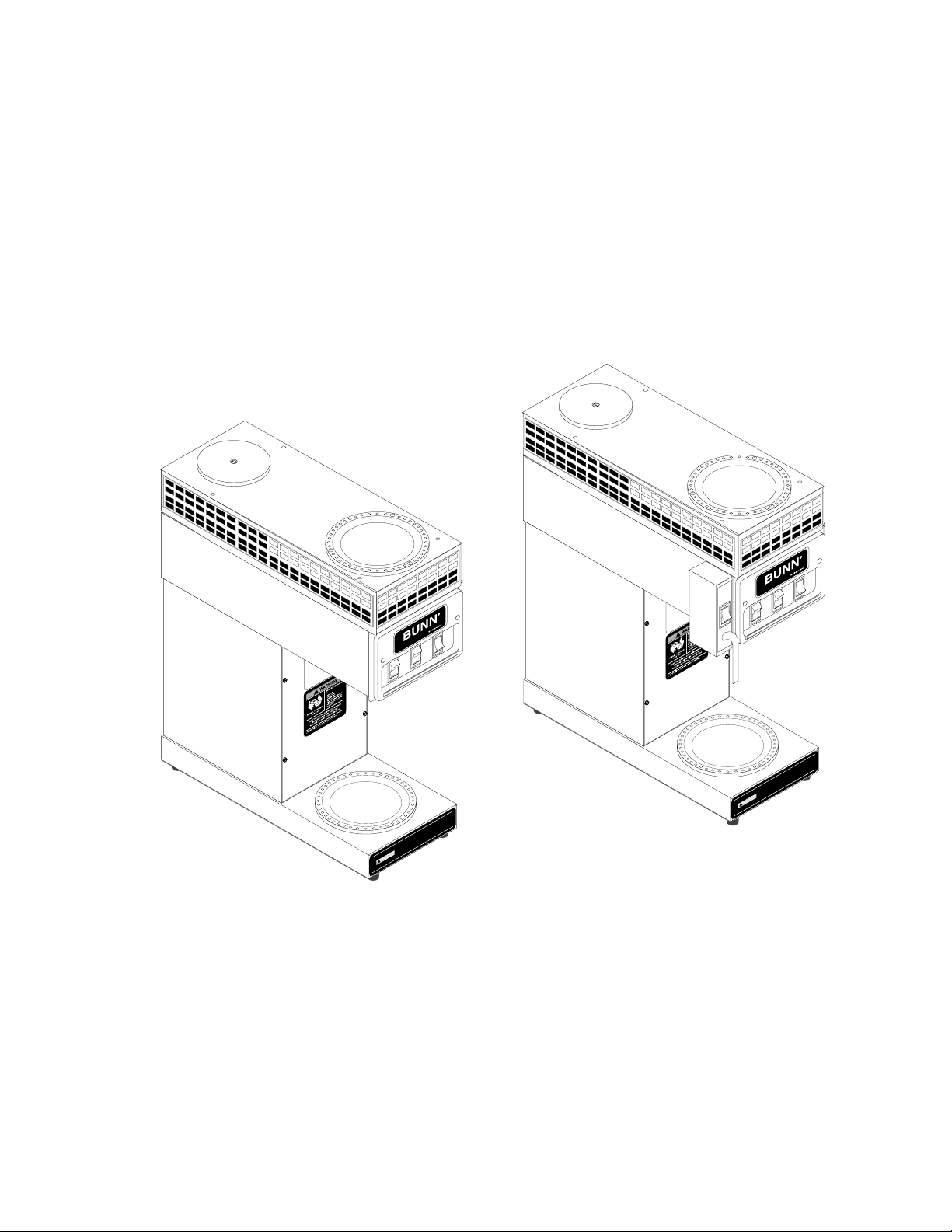
This equipment will brew a half-gallon batch of coffee into an awaiting decanter at the press of a button. It
has two individually controlled warmers to keep the beverage in the decanters at the right temperature. The
model SLF will also dispense hot water on demand for other purposes. The brewer is only for indoor use on a
sturdy counter or shelf.
WARRANTY
Bunn-O-Matic Corp. (“Bunn”) warrants the equipment manufactured by it to be commercially free from defects
in material and workmanship existing at the time of manufacture and appearing within one year from the date of
installation. In addition:
1.) Bunn warrants electronic circuit and/or control boards to be commercially free from defects in material and
workmanship for two years from the date of installation.
2.) Bunn warrants the compressor on refrigeration equipment to be commercially free from defects in material
and workmanship for two years from the date of installation.
3.) Bunn warrants that the grinding burrs on coffee grinding equipment will grind coffee to meet original factory
screen sieve analysis for three years from date of installation or for 30,000 pounds of coffee, whichever comes first.
This warranty does not apply to any equipment, component or part that was not manufactured by Bunn or that,
in Bunn’s judgement, has been affected by misuse, neglect, alteration, improper installation or operation, improper
maintenance or repair, damage or casualty.
THE FOREGOING WARRANTY IS EXCLUSIVE AND IS IN LIEU OF ANY OTHER WARRANTY, WRITTEN OR
ORAL, EXPRESS OR IMPLIED, INCLUDING, BUT NOT LIMITED TO, ANY IMPLIED WARRANTY OF EITHER
MERCHANTABILITY OR FITNESS FOR A PARTICULAR PURPOSE. The agents, dealers or employees of Bunn are
not authorized to make modifications to this warranty or to make additional warranties that are binding on Bunn.
Accordingly, statements by such individuals, whether oral or written, do not constitute warranties and should not
be relied upon.
The Buyer shall give Bunn prompt notice of any claim to be made under this warranty by telephone at (217)
529-6601 or by writing to Post Office Box 3227, Springfield, Illinois, 62708-3227. If requested by Bunn, the Buyer
shall ship the defective equipment prepaid to an authorized Bunn service location. If Bunn determines, in its sole
discretion, that the equipment does not conform to the warranty, Bunn shall repair the equipment with no charge
for parts during the warranty period and no charge for labor by a Bunn Authorized Service Representative during
the warranty period. If Bunn determines that repair is not feasible, Bunn shall, at its sole option, replace the
equipment or refund the purchase price for the equipment.
Page 2
(Revised November 1999)
Page 3
WARRANTY (cont.)
THE BUYER’S REMEDY AGAINST BUNN FOR THE BREACH OF ANY OBLIGATION ARISING OUT OF THE SALE
OF THIS EQUIPMENT, WHETHER DERIVED FROM WARRANTY OR OTHERWISE, SHALL BE LIMITED, AS
SPECIFIED HEREIN, TO REPAIR OR, AT BUNN’S SOLE OPTION, REPLACEMENT OR REFUND.
In no event shall Bunn be liable for any other damage or loss, including, but not limited to, lost profits, lost sales,
loss of use of equipment, claims of Buyer’s customers, cost of capital, cost of down time, cost of substitute
equipment, facilities or services, or any other special, incidental or consequential damages.
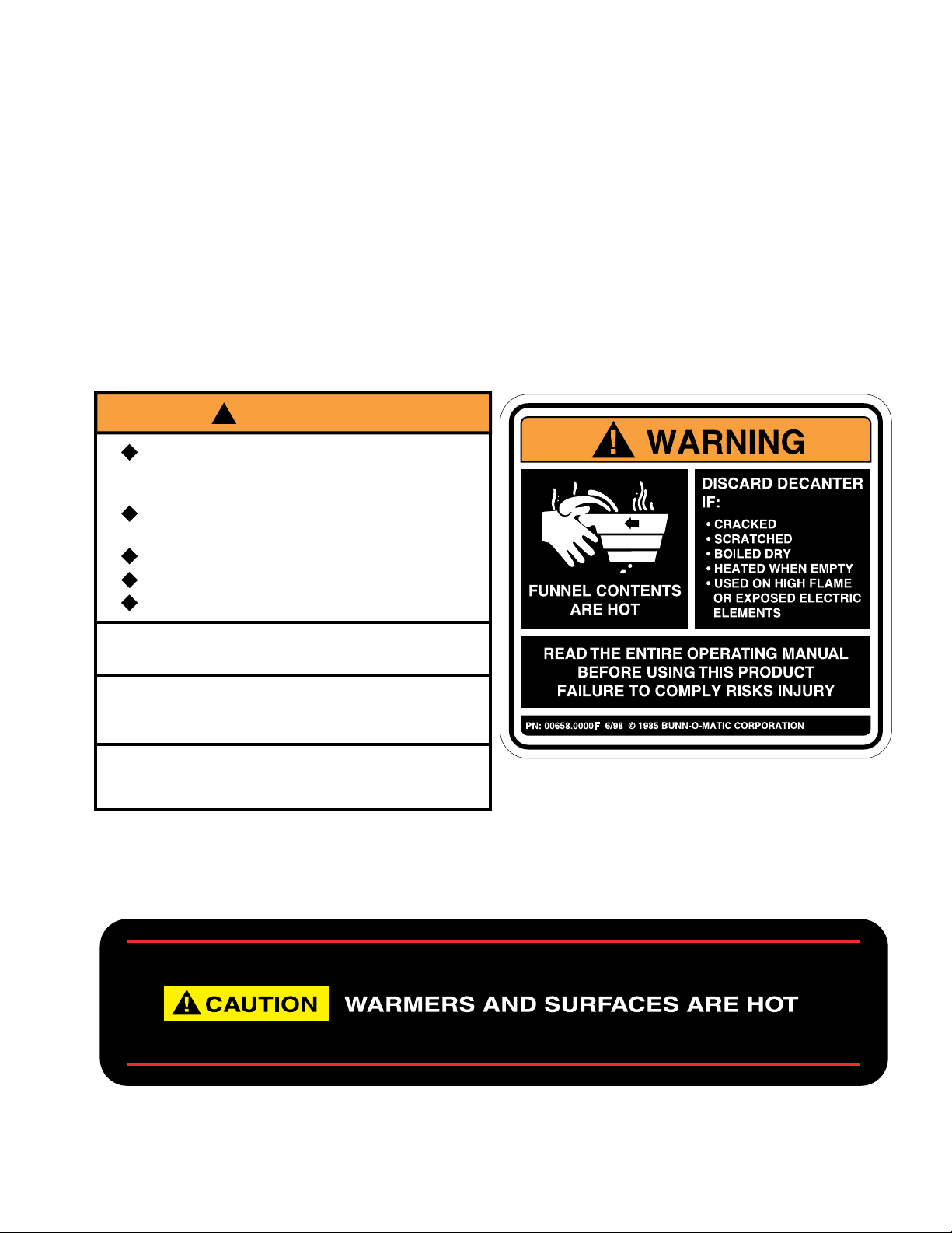
USER NOTICES
Carefully read and follow all notices on the equipment and in this manual. They were written for your protection.
All notices on the equipment should be kept in good condition. Replace any unreadable or damaged labels.
00831.0000
!
WARNING
Fill water tank before turning -on
thermostat or connecting appliance
to power source.
Use only on a properly protected
circuit capable of the rated load.
Electrically ground the chassis.
Follow national/local electrical codes.
Do not use near combustibles.
FAILURE TO COMPLY RISKS EQUIPMENT
DAMAGE, FIRE, OR SHOCK HAZARD
READ THE ENTIRE OPERATING MANUAL
BEFORE BUYING OR USING THIS PRODUCT
THIS APPLIANCE IS HEATED WHENEVER
CONNECTED TO A POWER SOURCE
00831.0000F 3/98 © 1988 BUNN-O-MATIC CORPORATION
00658.0000
02769.0000
Page 3
(Revised November 1999)
Page 4
USER NOTICES (cont.)
00656.0000
This equipment is to be installed to
comply with the Basic Plumbing Code of
12744.0000
WARNING
HOT
WATER
the Building Officials and Code
Administrators International, Inc. (BOCA)
and the Food Service Sanitation Manual
of the Food and Drug Administration (FDA).
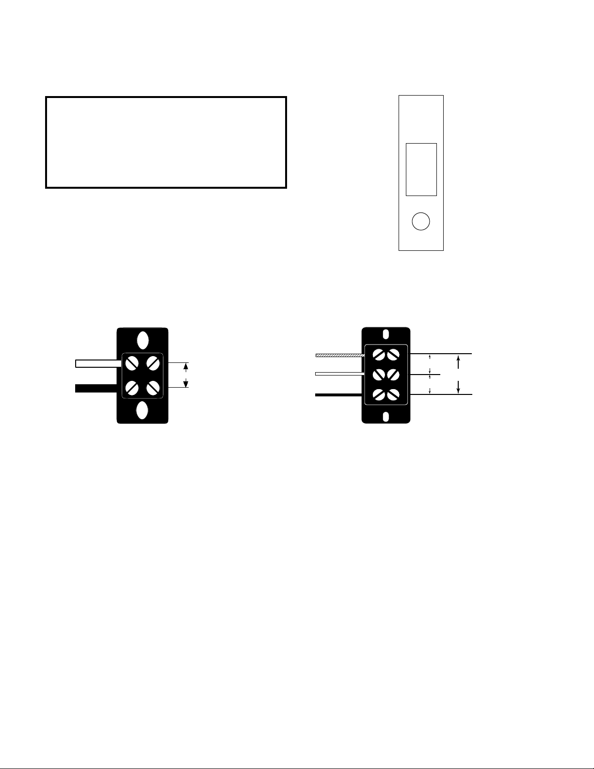
ELECTRICAL REQUIREMENTS
CAUTION - Do not connect the brewer to the power source until specified in Initial Set-Up.
WHITE
NEUTRAL
L1 BLACK
120V.A.C.
L2 RED
WHITE
NEUTRAL
120 V.A.C.
120 V.A.C.
208 or 240
Volts A.C.
L1 BLACK
MODEL 15 has an attached cordset, and requires 2-wire
grounded service rated 120 volts ac, 15 amp, single phase, 60
Hz.
MODEL 20 requires 2-wire, grounded service rated 120 volts
ac, 20 amp, single phase, 60 Hz. Proceed as follows:
MODEL35 requires 3-wire,
grounded service rated 120/208
or 120/240 volts ac, 20 amp,
single phase, 60 Hz. Proceed as
follows:
Electrical Hook-Up
CAUTION – Improper electrical installation will damage electronic components.
1. An electrician must provide electrical service as specified.
2. Using a voltmeter, check the voltage and color coding of each conductor at the electrical source.
3. Remove the front panel beneath the sprayhead and rotate the control thermostat knob fully counterclockwise
to the “OFF” position.
4. Remove the rear panel, feed the cord through the strain relief at the rear of the brewer, and connect it to the
terminal block. Replace the rear panel.
5. Connect the brewer to the power source and verify the voltage at the terminal block before proceeding.
Replace the front panel.
6. If plumbing is to be hooked up later, make sure that the brewer is disconnected from the power source. If
plumbing has been hooked up, the brewer is ready for Initial Set-Up.
Page 4
(Revised November 1999)
Page 5

PLUMBING REQUIREMENTS
This brewer must be connected to a cold water system with operating pressure greater than 10 psi from a
1/2” or larger supply line. A shut-off valve should be installed in the line before the brewer . Install a regulator in
the line when pressure is greater than 90 psi to reduce it to 50 psi. The water inlet fitting is 1/4" flare.
NOTE - Bunn-O-Matic recommends 1/4" copper tubing for installations of less than 25 feet from the 1/2" or larger
supply line. A tight coil of copper tubing in the water line will facilitate moving the brewer to clean the counter
top. Bunn-O-Matic does not recommend the use of a saddle valve to install the brewer . The size and shape of the
hole made in the supply line by this type of device may restrict water flow.
This equipment must be installed to comply with the Basic Plumbing Code of the Building Officials and Code Administrators International, Inc. (BOCA) and the Food Service
Sanitation Manual of the Food and Drug Administration (FDA).
Plumbing Hook-Up
1. Make certain that the 1/4" female flare fitting on the short tube from the outlet of the water strainer is securely
attached to the male bulkhead fitting on the brewer.
2. Flush the water line and securely attach it to the 1/4" flare fitting on the strainer.
3. Turn on the water supply.
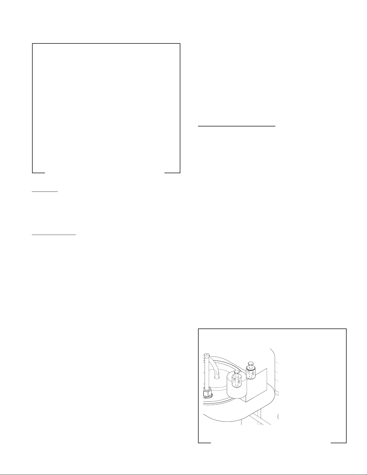
INITIAL SETUP
CAUTION - The brewer must be disconnected from the power source throughout the initial setup, except when
specified in the instructions.
1. Remove the front panel from the brewer.
2. Rotate the control thermostat knob fully counterclockwise to the "OFF" position and replace the panel.
3. Insert an empty funnel into the funnel rails.
4. Place a decanter containing a small amount of water on the warmer beneath the brew funnel.
5. Connect the brewer to the power source and place the On/Lower switch in the upper position.
6. Momentarily press the start switch. Approximately 64 ounces of water will flow into the brew tank. T o fill the
tank, it will be necessary to start two more brew cycles. Place the On/Lower switch in the lower position
when water starts flowing form the funnel into the decanter.
7. Disconnect the brewer from the power source and remove the front panel.
8. Rotate the control thermostat knob fully clockwise to the "ON" position and replace the panel.
9. Connect the brewer to the power source and wait for the water in the tank to heat to the proper temperature.
Some water will drip from the funnel during this time; this is due to expansion and should not occur thereafter .
10. Place an empty decanter under the funnel.
11. Place the On/Lower switch in the upper position and momentarily press the start switch. Empty the decanter
after water has stopped flowing from the funnel and return it to the warmer.
12. Allow the water in the tank to reheat to the proper temperature.
13. Momentarily press the start switch. Check the water volume in the decanter after water has stopped flowing
from the funnel. It should be 64 ounces.
14. If not, disconnect the brewer from the power source and remove the top lid.
15. Add or remove washers to the float on the level switch as required and replace the top lid. Adding washers
increases the volume, removing washers decreases it.
16. Repeat steps 12-15 until the proper water volume is achieved.
17A. Model SL:
The brewer is now ready for use in accordance with the coffee brewing instructions on page 6.
17B. Model SLF:
Momentarily press the hot water dispense switch a few times to clear any air from the dispense lines.
18. Allow the tank to fully reheat.
Page 5
(Revised November 1999)
Page 6

INITIAL SET-UP (cont.)
19. Press the hot water switch to dispense exactly 20 ounces of hot water and immediately start a brew cycle into
an empty graduated vessel.
20. Measure the brew water volume:
if it is more than the amount measured in #16, remove the rear panel, turn the needle valve slightly clockwise,
and replace the rear panel.
If it is less than the amount measured in #16, remove the rear panel, turn the needle valve slightly counterclockwise, and replace the rear panel.
21. Repeat steps 18-20 until the hot water refill rate is balanced with the dispense rate.
OPERATING CONTROLS
A. On/Lower Switch
Placing the switch in the upper position enables brewing and energizes the decanter warmer beneath the
funnel.
Placing the switch in the lower position cuts power to the warmer beneath the brew funnel and stops the
brew cycle. Stopping a brew cycle after it has been started will not stop the flow of water into the funnel until
the tank syphons down to its proper level.
B. Top Warmer Switch
Placing the switch in the upper position energizes the top warmer.
Placing the switch in the lower position cuts power to the top warmer.
C. Start Switch
Momentarily pressing this switch initiates a brew cycle when the On/Lower switch is in the upper position.
D. Hot Water Dispense Switch (Model SLF only)
Placing the switch in the lower position dispenses hot water and at the same time refills the tank. Dispensing/refilling occurs for as long as the switch is held.
CLEANING
1. The use of a damp cloth rinsed in any mild, non-abrasive, liquid detergent is recommended for cleaning all
surfaces on Bunn-O-Matic equipment.
2. Check and clean the sprayhead. The sprayhead holes must always remain open.
3. Disconnect the brewer from the power source. Remove the sprayhead and insert the deliming spring (provided) all the way into the sprayhead tube. When inserted properly , no more than two inches of spring should
be visible. Saw back and forth five or six times.
NOTE - In hard water areas, this may need to be done daily . It will help prevent liming problems in the brewer and
takes less than a minute.
COFFEE BREWING
1. Insert a BUNN® filter into the funnel .
2. Pour the fresh coffee into the filter and level the bed of grounds by gently shaking.
3. Slide the funnel into the funnel rails.
4. Place an empty decanter under the brew funnel.
5. Place the On/Lower switch in the upper position and momentarily press the start switch.
6. When brewing is completed, simply discard the grounds and filter.
Page 6
(Revised November 1999)
Page 7

TROUBLESHOOTING
A troubleshooting guide is provided to suggest probable causes and remedies for the most likely problems
encountered. If the problem remains after exhausting the troubleshooting steps, contact the Bunn-O-Matic
Technical Service Department.
• Inspection, testing, and repair of electrical equipment should be performed only by qualified service personnel.
• All electric components have 120 volt ac voltage on their terminals. Shorting of terminals or the application
of external voltages may result in equipment failure.
• Intermittent operation of electronic equipment is unlikely. Component failure will normally be permanent. If
an intermittent condition is encountered, the cause will likely be a switch contact or a loose connection at a
terminal or crimp.
• Solenoid removal requires interrupting the water supply to the valve. Damage may result if solenoids are
energized for more than ten minutes without a supply of water.
• The use of two wrenches is recommended whenever plumbing fittings are tightened or loosened. This will
help to avoid twists and kinks in the tubing.
• Make certain that all plumbing connections are sealed and electrical connections tight and isolated.
• This brewer is heated at all times unless disconnected from the power source. Keep away from combustibles.
WARNING
• Exercise extreme caution when servicing electrical equipment.
• Disconnect the brewer from the power source when servicing, except when electrical tests are specified.
• Follow recommended service procedures
• Replace all protective shields or safety notices
Problem
Equipment will not operate.
Brew cycle will not start.
Probable Cause
1. No power or incorrect voltage
1. No water
2. Water Strainer
3. Water Level Switch and Overflow
Safety Switch
Remedy
(A) Connect the brewer to the power
source.
(B) Check the terminal block for the
proper voltages.
(C) Check circuit breaker/fuse.
Check plumbing and shut-off valves.
(A) Direction of flow arrow must be
pointing towards brewer.
(B) Remove the strainer and check
for obstructions. Clear or replace.
Refer to Service - Water Level Switch
and Overflow Safety Switch for testing procedures. See page 23.
Page 7
(Added November, 1999)
Page 8

TROUBLESHOOTING (cont.)
Problem
Brew cycle will not start. (cont.)
Water flows into fill basin continuously (On/Lower brew station
warmer switch "OFF").
Water flows into fill basin continuously (On/Lower brew station
warmer switch "ON").
Probable Cause
4. On/Lower Brew Station Warmer
Switch
5. Start Switch
6. Relay
7. Solenoid Valve
1. Solenoid Valve
1. Start Switch
Remedy
Refer to Service - On/Lower Brew
Station Warmer Switch for testing
procedures. See page 15.
Refer to Service - Start Switch for
testing procedures. See page 16.
Refer to Service - Relay for testing
procedures. See page 21.
Refer to Service - Solenoid Valve for
testing procedures. See page 17.
Refer to Service - Solenoid Valve for
testing procedures. See page 17.
Refer to Service - Start Switch for
testing procedures. See page 16.
Water is not hot.
Decanter warmer is not hot.
1. Limit Thermostat
CAUTION
Do not eliminate or bypass limit thermostat. Use only B.O.M. replacement part #29329.1000
2. Control Thermostat
3. Tank Heater
1. Warmer Switches
Refer to Service - Limit Thermostat
for testing procedures. See page 17.
Refer to Service - Control Thermostat for testing procedures. See
page 13.
Refer to Service - Tank Heater for
testing procedures. See page 22.
(A) The Warmer Switch(es) must be
in the "ON" position for the warmer
to operate.
(B) Refer to Service - Warmer
Switch(es) for testing procedures.
See pages 15.
2. Decanter Warmers
Page 8
Refer to Service - Warmers for testing procedures. See pages 14.
(Added November, 1999)
Page 9

TROUBLESHOOTING (cont.)
Problem
Spitting or unusual steaming from
sprayhead.
Warmer plates too hot, solenoid coil
smoking, or water in tank heats excessively fast.
Probable Cause
1. Control Thermostat
2. Lime build-up
CAUTION
Tank and tank components should
be delimed regularly depending on
local water conditions. Excessive
mineral build-up on stainless steel
surfaces can initiate corrosive reactions resulting in serious leaks.
1. Brewer wired to wrong voltage
Remedy
Refer to Service - Control Thermostat for testing procedures. See
page 13.
Inspect the tank assembly for excessive lime deposits. Delime as required.
Refer to Electrical Requirements Page 4.
Inconsistent beverage level in decanter.
Dripping from sprayhead.
1. Improper water pressure
2. Syphon system
3. Hot water Dispense flow adjustment (SLF only)
1. Syphon system
2. Solenoid Valve
Check the operating water pressure
to the brewer. It must be between
10 and 90 psi.
Water should flow freely from the
sprayhead and then stop abruptly.
The brewer must be level from frontto-back to syphon properly.
Refer to Service - Hot Water Dispense Valve - Page 19 and Inlet Solenoid Valve - Page 20.
Water should flow freely from the
sprayhead and then stop abruptly.
The brewer must be level from frontto-back to syphon properly.
Refer to Service - Solenoid Valve for
testing procedures. See page 17.
Page 9
(Added November, 1999)
Page 10

TROUBLESHOOTING (cont.)
Problem
Probable Cause
Remedy
No hot water dispensed from faucet
(SLF only)
Beverage overflows decanter.
Weak beverage.
1. Hot Water Switch
2. Hot Water Dispense Valve
3. Inlet Solenoid Valve (Faucet)
1. Beverage left in decanter
1. Type of paper filters
2. Coffee
Refer to Service - Hot Water Switch
for testing procedures. See page 24.
Refer to Service - Hot Water Dispense Valve for testing procedures.
See page 19.
Refer to Service - Inlet Solenoid
Valve (faucet) for testing procedures. See page 20.
The brew cycle should be started
only with an empty decanter under
the funnel.
BUNN® paper filters should be used
for proper extraction.
A sufficient quantity of fine or drip
grind coffee should be used for
proper extraction.
3. Sprayhead
4. Funnel loading
5. Water temperature
B.O.M. sprayhead #01082.0000
should be used to properly wet the
bed of ground coffee in the funnel.
The BUNN® paper filter should be
centered in the funnel and the bed
of coffee leveled by gentle shaking.
Place a funnel over an empty decanter on the warmer beneath the
sprayhead. Place the On/Lower
brew station warmer switch in the
upper position, press the start
switch, and check the water temperature immediately below the
sprayhead with an accurate thermometer. The reading should not
be less than 195° F. Adjust the control thermostat slightly clockwise to
increase the water temperature.
Page 10
(Added November 1999)
Page 11

TROUBLESHOOTING (cont.)
Problem
Brewer is making unusual noises.
Probable Cause
1. Solenoid Valve
2. Plumbing lines
3. Water supply
Remedy
The nut on top of the solenoid valve
must be tight or it will vibrate during operation.
Plumbing lines should not rest on
the counter top.
(A) The brewer must be connected
to a cold water line.
(B) Water pressure to the brewer
must not be higher than 90 psi. Install a regulator if necessary to lower
the working pressure to approximately 50 psi.
Page 11
(Added November 1999)
Page 12

SERVICE
This section provides procedures for testing and replacing various major components used in this brewer
should service become necessary. Refer to Troubleshooting for assistance in determining the cause of any
problem.
Component Access
WARNING - Disconnect the brewer from the power
source before the removal of any panel or the replacement of any component.
The overflow safety switch, warmer switches, hot
water dispense valve(SLF only) and start switch are
located under the top cover or top warmer housing,
FIG. 1, attached with four #6-32 slotted-head screws.
The solenoid valve, relay, control thermostat and
terminal block are located in the trunk. Access is
gained by removing the front access panel, FIG. 1 attached with four #8-32 slotted-head screws
The inlet solenoid valve (SLF only), limit thermo-
stat, tank heater and tank “keep warm” heater are located on the tank assembly. Access is gained by removing the rear panel, FIG. 1 attached with four #832 slotted head screws.
N
S
M
I
A
H
W
R
N
E
G
E
R
IA
G
D
G
I
H
IN
W
IR
W
5
W
2
4
R
1
E
IC
T
A
T
I
E
H
A
H
W
K
N
M
A
T
K
E
IT
L
B
H
AT
IM
T
L
R
S
C
W
E
0
O
T
5
S
M
A
R
E
E
H
" H
T
M
I
R
H
A
W
W
P
E
. &
T
U
E
I
A
L
W
"K
H
T
B
S
S
W
O
M
2
P
ER
H
T
F
O
S
I
H
IN
IN
W
1
W
E P
-P
L
0
R
E
0
E
1
A
R
3
R
H
I
P
A
T
H
E
.
D
, &
W
R
R
E
2
R
P
K
IZ
TO
E
O
L
, P
C
T
B
M
1
E
AR
P
R
L
N
A
K
O
N
L
W
O
P
/B
C
A
U
I
H
BL
W
1
P
I
W
0
H
0
W
1
T
N
O
FR
R
K
P
E
L
O
B
M
/
T
R
U
K
A
L
L
B
W
/B
N
R
B
3
P
N
O
W
I
0
T
K
0
A
R
L
1
E
R
B
O
M
P
R
R
A
O
K
W
L
C
R
B
/
IC
E
T
N
W
A
R
O
B
M
L
-
-O
N
N
U
8 B
8
9
K
1
L
B
©
7
/9
IO
3
D
I/V
0
H
0
0
W
.0
3
4
0
0
1
E
R
I
W
2
K
L
C
B
E
A
S
A
S
T
H
L
P
O
E
V
L
Z
0
G
H
2
N
I
1
0
S
6
R
A
E
O
T
R
P
O
T
T
R
A
T
S
T
N
O
R
F
P
O
R
T
E
W
O
/ L
N
O
R
E
W
O
L
T
N
O
R
F
P
O
T
R
A
E
R
P
WARNING - Inspection, testing, and repair of electrical equipment should be performed only by qualified
service personnel. The brewer should be disconnected
from the power source when servicing, except when
electrical tests are required and the test procedure
specifically states to connect the brewer to the power
source.
Contents
Control Thermostat...............................................13
Warmer(s) ............................................................14
Warmer Switch(es)...............................................15
Start Switch..........................................................16
Limit Thermostat ..................................................17
Brew Solenoid Valve.............................................17
Hot Water Dispense Valve(optional) .....................19
Inlet Solenoid Valve (faucet-optional)...................20
Relay.....................................................................21
Tank Heater...........................................................22
Overflow Safety Switch.........................................23
Hot Water Switch (optional) .................................24
Replacement parts................................................25
Wiring Schematics............................................... 26
P1712
T
U
A
C
!
FIG. 1 ACCESS PANELS
T
O
H
E
R
A
S
E
C
A
F
R
U
S
D
N
A
S
R
E
M
R
A
W
N
IO
Page 12
(Added November 1999)
Page 13

SERVICE (cont.)
Control Thermostat
P1478
FIG. 2 CONTROL THERMOSTAT
Location:
The control thermostat is located inside the front
access panel, FIG. 2.
T o test the control thermostat, access will also be
needed to the tank heater located in the bottom of the
tank assembly .
4. With a voltmeter, check the voltage across the
black wire terminal of the control thermostat and
the white wire on the tank heater when the control
thermostat is turned "ON" (fully clockwise). Connect the brewer to the power source. The indication must be as described in step 2. Voltage must
not be indicated across these terminals when the
thermostat is turned "OFF" (fully counterclockwise).
5. Disconnect the brewer from the power source.
If voltage is present as described, the control thermostat is operating properly.
If voltage is not present as described, replace the control thermostat.
Removal and Replacement:
1. Remove the front access panel from the brewer
to gain access.
2. Remove both wires from the control thermostat
terminals.
3. Remove the thermostat bulb by firmly pulling-up
on the capillary tube at the tank lid. This will disengage the grommet from the tank lid.
4. Remove the two #8-32 screws holding the control thermostat to the bracket.
5. Fasten the new control thermostat to the component bracket.
Test Procedure:
1. Disconnect the brewer from the power source.
2. With a voltmeter, check the voltage across the blue/
black wire on the control thermostat and the white
wire on the tank heater. Connect the brewer to
the power source. The indication must be 120
volts ac for two wire 120 volt models and three
wire 120/240 volt models.
3. Disconnect the brewer from the power source.
If voltage is present as described, proceed to #4.
If voltage is not present as described, refer to the Wiring Diagrams and check the brewer wiring harness.
NOTE - Make sure that the capillary tube is away from
any electrical termination and is not kinked.
6. Slide the grommet to the red mark on the capillary tube.
7. Insert the bulb through the hole in the tank lid and
press the grommet firmly and evenly so that the
groove in the grommet fits into the tank lid.
8. Carefully bend the capillary tube so that the tube
and bulb inside the tank are in a vertical position.
9. Refer to FIG. 3 when reconnecting the wires.
10. Readjust the control thermostat dial as required.
Page 13
(Added November 1999)
Page 14

SERVICE (cont.)
If continuity is present as described, proceed to #5.
5. Check for continuity from the wire terminal of the
blue/black or violet wire to the warmer switch.
If continuity is present as described, proceed to #6.
If continuity is not present as described, refer to the
Wiring Diagrams and check the brewer wiring harness.
6. Check for continuity across the two terminals on
the warmer.
If continuity is present as described, the warmer is
operating properly.
If continuity is not present as described, replace the
warmer.
Removal and Replacement:
1. Remove the #4-40 slotted-head screws holding
the warmer to the brewer
2. Lift the warmer assembly from the brewer.
3. Disconnect both wires from the warmer.
4. Refer to FIG. 5 when reconnecting the wires.
5. Place the new warmer into the brewer and securely
attach it using the #4-40 screws.
FIG. 4 WARMERS
Location:
One of the warmers is beneath the brew funnel
and the other is on the top lid, FIG. 4.
Test Procedure:
1. Once the switch has been tested and switch failure has been eliminated, proceed as follows.
2. Disconnect the brewer from the power source and
remove the #4-40 screws attaching the warmer
being tested.
3. Lift the warmer assembly from the brewer and
invert the warmer making the wire terminals accessible for testing.
4. Check for continuity from the switch to the white
wire at the warmer element.
FIG. 5 WARMER WIRING
Page 14
Page 15

SERVICE (cont.)
Warmer Switch(es)
N
S
M
I
A
H
W
R
N
G
E
E
A
R
I
G
D
G
I
N
H
I
W
R
I
W
W
5
2
4
R
C
1
E
I
T
A
T
I
E
H
H
A
W
K
N
M
A
T
K
T
E
I
L
T
B
M
H
A
I
T
L
R
S
C
W
E
0
O
T
5
S
M
A
R
E
E
H
H
"
T
M
I
R
H
A
W
W
P
&
E
.
T
U
E
I
L
A
K
W
"
H
T
B
S
S
W
O
M
2
R
P
E
H
T
F
O
S
I
N
H
I
N
I
P
W
1
P
W
E
-
L
0
R
E
0
E
A
1
R
3
R
H
P
I
A
T
H
E
.
&
D
,
R
W
R
E
2
O
R
Z
P
K
P
I
T
E
O
L
,
R
C
T
B
M
1
E
A
P
R
L
N
A
K
O
N
L
P
W
O
B
C
/
A
U
I
L
H
B
W
1
P
I
W
0
H
0
W
1
T
N
O
R
F
R
K
P
E
L
O
B
M
/
T
R
U
K
A
L
L
B
W
B
/
N
R
B
3
P
N
O
W
I
0
T
0
K
R
A
1
L
E
R
B
O
M
P
R
R
A
O
K
W
C
L
R
B
C
/
E
I
T
N
W
A
R
O
B
M
L
-
O
-
N
N
U
B
8
8
9
1
K
L
B
©
7
9
/
3
O
I
V
/
D
I
0
H
0
0
W
0
.
3
4
0
0
1
E
R
I
W
2
K
L
C
B
E
A
S
A
S
T
H
L
P
O
E
V
L
Z
0
G
H
2
N
I
1
0
S
6
START
R
TOP FRONT
ON / LOWE
LOWER
OP FRONT
T
AR
TOP REAR
TOP RE
T
O
H
E
R
A
S
E
C
A
F
R
U
S
D
N
A
S
R
E
M
R
A
W
N
O
I
T
U
A
C
!
FIG. 6 WARMER SWITCHES
Location:
These switches are the two left switches on the
switch panel, FIG 6.
P2012
If voltage is present as described the switch is operating properly.
If voltage is not present as described, replace the
switch.
Removal and Replacement:
1. Compress the clips inside the housing and gently
push the switch through the opening.
2. Remove the wires from the switch terminals.
3. Refer to FIG. 7 when reconnecting the wires.
4. Push the new switch firmly into the opening.
Top Warmer
WHI to Top
Warmer, WHI to
On/Lower Switch
BLK to On/Lower
Switch
Test Procedure:
1. Locate the switch terminal with black wires.
2. Check the voltage across this terminal and the terminal on the indicator lamp with white wire with a
voltmeter. Connect the brewer to the power
source. The indication must be 120 volts ac for
two wire 120 volt models and three wire 120/240
volt models.
3. Disconnect the brewer from the power source.
If voltage is present as described, proceed to #4.
If voltage is not present as described, refer to the Wiring Diagrams and check the brewer wiring harness.
4. With a voltmeter , check the voltage across the remaining switch terminal and the terminal on the
indicator lamp with white wire when the switch is
in the upper position. Connect the brewer to the
power source. The indication must be as described in step 2. Voltage must not be present
across these terminals in the lower position.
5. Disconnect the brewer from the power source.
BLU/BLK to Top
Warmer
On/Lower Warmer
WHI to Top Warmer
Switch and WHI to
Terminal Block
(White Insert)
BLK to Top
Warmer and BLK
to Terminal Block
(Black Insert)
WHI/RED to
Overflow Safety
Switch and VIO to
Lower Warmer
P1590
FIG. 7 WARMER SWITCH WIRING
Page 15
(Added November 1999)
Page 16

SERVICE (cont.)
Start Switch
N
S
M
I
A
H
W
R
N
E
G
E
R
A
G
I
D
G
I
N
H
I
W
R
I
W
W
5
2
4
R
C
1
E
I
T
A
T
I
E
H
H
A
W
K
N
M
A
T
K
T
E
I
L
T
B
M
H
A
I
T
L
R
S
W
C
E
0
O
T
5
S
M
A
R
E
E
H
H
"
T
M
I
R
H
A
W
W
P
&
E
.
T
U
E
I
L
A
K
W
"
H
T
B
S
S
W
O
M
2
R
P
E
H
T
F
O
S
I
N
H
I
N
I
P
W
1
P
W
E
-
L
0
R
E
0
E
A
1
R
3
R
H
P
I
A
T
H
E
.
&
D
,
R
W
R
E
2
O
R
Z
P
K
P
I
T
E
O
L
,
R
C
T
B
1
M
E
A
P
R
L
N
A
K
O
N
L
P
O
W
B
C
/
A
U
I
L
H
B
W
1
P
I
W
0
H
0
W
1
T
N
O
R
F
R
K
P
E
L
O
B
M
/
T
R
U
K
A
L
L
B
W
B
/
N
R
B
3
P
N
O
W
I
0
T
K
0
R
A
L
1
E
R
B
O
M
P
R
R
A
O
K
W
C
L
R
B
C
/
E
I
T
N
W
A
R
O
B
M
L
-
O
-
N
N
U
B
8
8
9
1
K
L
B
©
7
9
/
3
O
I
V
D
/
I
0
H
0
0
W
0
.
3
4
0
0
1
E
R
I
W
2
K
L
C
B
E
A
S
A
S
T
H
L
P
O
E
V
L
Z
0
G
H
2
N
I
1
0
S
6
T
R
A
T
S
T
N
O
R
F
P
O
R
T
E
W
O
L
/
N
O
R
E
W
O
L
T
N
O
R
F
P
O
T
R
A
E
R
R
A
P
E
O
R
T
P
O
T
T
O
H
E
R
A
S
E
C
A
F
R
U
S
D
N
A
S
R
E
M
R
A
W
N
O
I
T
U
A
C
!
FIG. 8 START SWITCH
If continuity is present as described, reconnect the
wires, the switch is operating properly.
If continuity is not present as described, replace the
switch.
Removal and Replacement:
1. Remove all wires from the switch terminals.
2. Compress the clips inside the housing and gently
push the switch through the opening.
3. Push the new switch into the opening and spread
the clips to hold the switch captive in the housing.
4. Refer to FIG. 9 when reconnecting the wires.
P2012
BLK to Relay
(K5)
Location:
The start switch is located on the far right of the
front switch panel , FIG 8.
Test Procedure:
1. Disconnect the brewer from the power source and
remove the wires from both terminals of the start
switch.
2. Check for continuity across the two terminals on
the switch when it is held in the lower position.
Continuity must not be present across these terminals in the upper position.
BRN/BLK to
Relay (K-A)
P1591
FIG. 9 START SWITCH WIRING
Page 16
(Added November 1999)
Page 17

SERVICE (cont.)
Limit Thermostat
FIG. 10 LIMIT THERMOSTAT
2. Carefully slide the limit thermostat out from under the retaining clip.
3. Carefully slide the new limit thermostat into the
retaining clip.
4. Refer to FIG. 11 when reconnecting the wires.
BLU/BLK to Control
Thermostat
BLK to Tank
Heater
P1715
Location:
The limit thermostat is located on the back of the
tank assembly, FIG. 10.
Test Procedure:
1. Disconnect the brewer from the power source.
2. Check voltage across the black wire from the limit
thermostat and the white wire on the tank heater
terminal. Connect the brewer to the power source.
The indication must be 120 volts ac for two wire
120 volt models and three wire 120/240 volt models.
3. Disconnect the brewer from the power source.
If voltage is present as described, proceed to #4.
If voltage is not present as described, refer to the Wiring Diagrams and check the brewer wiring harness.
4. Check for continuity across the limit thermostat
terminals.
P1984
FIG. 11 LIMIT THERMOSTAT WIRING
Solenoid Valve
If continuity is present as described, the limit thermostat is operating properly.
If continuity is not present as described, replace the
limit thermostat.
Removal and Replacement:
1. Remove both wires from the limit thermostat terminals.
FIG. 12 SOLENOID VALVE
Location:
The solenoid valve is located inside the front access
panel, near the bottom of the bracket, FIG. 12
Page 17
(Added November 1999)
P2014
Page 18

SERVICE (cont.)
Solenoid Valve(cont.)
Test Procedure:
1. With a voltmeter check the voltage across the
white and the white/red wires when the On/Lower
brew station warmer switch is in the upper position and the start switch is pressed to the lower
position and released. Connect the brewer to the
power source. The indication must be 120 volts
ac for two wire 120 volt models and three wire
120/240 volt models,
2. Disconnect the brewer from the power source.
If voltage is present as described, proceed to #3.
If voltage is not present as described, refer to the Wiring Diagrams and check the brewer wiring harness.
3. Remove all wires from the coil. Check for continuity across the solenoid valve coil terminals.
If continuity is present as described, reconnect the
white and the white/red wires and proceed to #4.
If continuity is not present as described, replace the
solenoid valve.
Removal and Replacement:
1. Disconnect the brewer from the power source.
2. Turn off the water supply to the brewer.
3. Remove the front access panel to gain access.
4. Disconnect all wires from the solenoid valve.
5. Disconnect the water lines to and from the solenoid valve.
6. Remove the two #8-32 screws which hold the
solenoid valve and mounting bracket to the component bracket.
7. Lift out the solenoid valve and bracket. Remove
the bracket from the solenoid valve and save to
mount the new valve.
8. Securely install the new solenoid valve to the
mounting bracket with two #10-32 screws. Check
the direction of flow arrow on the valve. It must
be pointing toward the tank inlet tube.
9. Securely attach the valve and bracket to the component bracket using the two #8-32 screws.
10. Securely fasten the water lines to and from the
solenoid valve.
11. Refer to FIG. 13 when reconnecting the wires.
4. Check the solenoid valve for coil action. Connect
the brewer to the power source, place the On/
Lower brew station warmer switch in the upper
position, press and release the start switch. Listen carefully in the vicinity of the solenoid valve
for a "clicking" sound as the coil magnet attracts
and after lifting of the level float switch, repels the
plunger .
5. Disconnect the brewer from the power source.
If the sound is heard as described and water will not
pass through the solenoid valve, there may be a blockage in the water line before or after the solenoid valve
or , the solenoid valve may require inspection for wear ,
and removal of waterborne particles.
If the sound is not heard as described, replace the
solenoid valve.
WHI/RED to Relay
WHI/RED to
(K7)
ON/OFF Switch
WHI to Relay (K-B)
WHI/GRN to
Brew Timer
Models ST & STA
FIG. 13 SOLENOID VALVE WIRING
P1588
Page 18
(Added November 1999)
Page 19

SERVICE (cont.)
HOT WATER DISPENSE VALVE (OPTIONAL)
Page 19
Page 20

SERVICE (cont.)
INLET SOLENOID VALVE (FAUCET - OPTIONAL)
P2021
FIG. 16 INLET SOLENOID VALVE
(FAUCET)
Location:
The Inlet Solenoid Valve (faucet) is located inside
the rear access panel, FIG. 16.
Test Procedures:
1. With a voltmeter check the voltage across the
white and the white/violet wires when the hot water dispense switch is pressed to the lower position and held. Connect the brewer to the power
source. The indication must be 120 volts ac for
two wire 120 volt models and three wire 120/240
volt models.
2. Disconnect the brewer from the power source.
If voltage is present as described, proceed to #3.
If voltage is not present as described, refer to the Wiring Diagrams and check the brewer wiring harness.
If the sound is heard as described and water will not
pass through the solenoid valve, there may be a blockage in the water line before or after the solenoid valve
or , the solenoid valve may require inspection for wear ,
and removal of waterborne particles.
If the sound is not heard as described, replace the
solenoid valve.
Removal and Replacement:
1. Disconnect the brewer from the power source.
2. Turn off the water supply to the brewer.
3. Remove the rear access panel to gain access.
4. Disconnect all wires from the solenoid valve.
5. Turn the needle valve handle clockwise to close
the needle valve.
6. Disconnect the water lines to and from the solenoid valve.
7. Remove the two #8-32 screws which hold the
solenoid valve and mounting bracket to the component bracket.
8. Lift out the solenoid valve and bracket. Remove
the bracket from the solenoid valve and save to
mount the new valve.
9. Securely install the new solenoid valve to the
mounting bracket with two #10-32 screws. Check
the direction of flow arrow on the valve. It must
be pointing toward the needle valve.
10. Securely attach the valve and bracket to the component bracket using the two #8-32 screws.
11. Securely fasten the water lines to and from the
solenoid valve.
12. Refer to FIG. 17 when reconnecting the wires.
13. Refer to Initial Set-Up for readjustment of the
needle valve (steps 18-20).
3. Remove all wires from the coil. Check for continuity across the solenoid valve coil terminals.
If continuity is present as described, reconnect the
white and the white/violet wires and proceed to #4.
If continuity is not present as described, replace the
solenoid valve.
4. Check the solenoid valve for coil action. Connect
the brewer to the power source, place the hot water
dispense switch in the lower position and release.
Listen carefully in the vicinity of the solenoid valve
for a “clicking” sound as the coil magnet attracts
and repels the plunger.
5. Disconnect the brewer from the power source.
Page 20
WHI/VIO to Hot Water
Dispense Valve
WHI to Hot Water
Dispense Valve
P2022
FIG. 17 INLET SOLENOID
VALVE WIRING
(Added November 1999)
Page 21

SERVICE (cont.)
Relay
FIG. 18 RELAY
Location:
The relay is located inside the front access panel,
near the top of the bracket, FIG. 18.
P2015
If continuity is present as described, reconnect the
black and white/red wires to the relay, relay is operating properly.
If continuity is not present as described, replace the
relay.
Removal and Replacement:
1. Disconnect the brewer from the power source.
2. Remove the top cover or top warmer housing.
3. Disconnect all wires from the relay.
4. Remove the two #8-32 screws attaching the relay
and bracket assembly to the component bracket.
5. Remove the #6-32 screw attaching the relay to
the bracket.
6. Securely attach the new relay to the bracket using
the #6-32 screw.
7. Attach the new relay and bracket assembly to the
component bracket using the two #8-32 screws.
8. Refer to FIG. 19 when reconnecting the wires.
Test Procedure:
1. Disconnect the brewer from the power source.
2. Remove the brown/black wire from the “A” terminal and the white wire from the “B” terminal on
the relay.
3. Check for continuity across the “A” and “B”
teminals.
If continuity is present as described, reconnect the
brown/black wires and white wires to the relay, FIG.
19, and proceed to #4.
If continuity is not present as described, replace the
relay.
4. Remove the black wire from terminal 5 and the
white/red wire from terminal 7 on the relay.
5. Check for continuity across terminals 5 and 7 by
manually closing the relay contact. Continuity
must be present when contact is released.
2 - No Wire
5 - BLK to Start Switch
B - WHI to Solenoid
7 - WHI/RED to Solenoid
A - BRN/BLK to Start
Switch
P1597
FIG. 19 RELAY TERMINALS
Page 21
(Added November 1999)
Page 22

SERVICE (cont.)
Tank Heater
P1715
FIG. 20 TANK HEATER
Location:
The tank heater is located in the bottom of the
tank assembly, FIG. 20.
Test Procedure:
1. Check the voltage across the black and white or
red wires on the tank heater with a voltmeter when
the control thermostat is turned "ON" (fully clockwise). Connect the brewer to the power source.
The indication must be:
a) 120 volts ac for two wire 120 volt models and
three wire 120/240 volt models
b) 240 volts ac for two wire 240 volt models.
2. Disconnect the brewer from the power source.
Removal and Replacement:
1. Disconnect the brewer from the power source.
2. Remove the top cover or top warmer housing and
the rear access panel.
3. Disconnect the wires to the tank heater.
4. Gently pull the thermostat bulb with grommet out
of the tank lid.
5. Disconnect and remove the fill basin tube.
6. Remove the four #8-32 nuts and hold-down brackets attaching the tank lid to the tank assembly and
remove the tank lid and gasket.
7. Drain the water from the tank using a syphon or
similar device.
8. Remove the two nuts securing the tank heater to
the bottom of the tank and remove the tank heater .
9. Install a new tank heater with new washers and
secure with two nuts. Nuts should be securely
tightened to insure a proper seal.
10. Install the tank lid and gasket using the four holddown brackets and #8-32 nuts.
11. Install the fill basin tube and tighten the nuts securely.
12. Slide the grommet to the red mark on the capillary tube.
13. Carefully bend the capillary tube so that the tube
and bulb inside the tank are in a vertical position.
14. Insert the bulb through the hole in the tank lid and
press the grommet firmly and evenly so that the
groove in the grommet fits into the tank lid.
15. Refer to FIG. 21 when reconnecting the wires.
16. Refer to Initial Setup to refill the tank.
If voltage is present as described, proceed to #3.
If voltage is not present as described, refer to the Wiring Diagrams and check the brewer wiring harness.
3. Check for continuity across the terminals of the
tank heater.
If continuity is present as described, reconnect the
wires, the tank heater is operating properly.
If continuity is not present as described, replace the
tank heater.
NOTE - If the tank heater remains unable to heat, remove and inspect the heater for cracks in the sheath.
Page 22
BLK to Limit Thermostat
WHI or RED to
Terminal Block
P1716
FIG. 21 TANK HEATER WIRING
(Added November 1999)
Page 23
SERVICE (cont.)
Water Level and Overflow Safety Switch
P2016
FIG. 22 WATER LEVEL and OVERFLOW
SAFETY SWITCHES
Location:
The water level and overflow safety switches are
located under the top cover or top warmer housing
and inside and front of the tank fill basin, FIG. 22.
Test Procedure:
1. Disconnect the brewer from the power source.
2. Remove the top cover or top warmer housing.
3. Remove the leads of the switch being tested from
the connection block mounted on the front of the
tank basin.
4. Check the voltage across the black lead of the con-
nection block and the white lead on the solenoid
coil with a voltmeter . T urn the On/Lower switch to
the “ON” position and connect the brewer to the
power source. The indication must be 120 volts
ac for two wire 120 volt models and three wire
120/240 volt models,
5. Disconnect the brewer from the power source.
7. Check for continuity across the water level switch
red wires only until the plastic float is raised and
check that continuity returns when the float is lowered again.
If continuity is present as described, reconnect the
wires as shown in FIG. 23, the switches are operating
properly .
If continuity is not present as described, replace the
switch.
Removal and Replacement:
1. Disconnect the brewer from the power source.
2. Remove the top cover or top warmer housing.
3. Remove the wire leads connecting the water level
and overflow switches to the connection block at
the front of the tank and fill basin.
4. Disconnect the #8-32 screw and remove the entire switch assembly from the tank and fill basin.
5. Place the new switch assembly into the bracket,
wires up.
NOTE- The magnets must be at the top of the float
and there must be NO adjusting washers installed for
the overflow safety switch to operate properly.
6. Install the nuts over the wires and secure the
switch to the mounting bracket. Do not over
tighten.
7. Attach the entire switch assembly to the tank and
fill basin using the #8-32 screw.
8. Add or remove washers to the float on the level
switch as required. Adding washers increases the
volume, removing washers decreases it.
9. Refer to FIG. 23 and the relative wiring diagram
when reconnecting wires.
If voltage is present as described, proceed to #6.
If voltage is not present as described, refer to the Wiring Diagrams and check the brewer wiring harness.
6. Check for continuity across the overflow switch
red wires only until the plastic float is raised and
check that continuity returns when the float is lowered again.
P1478
FIG. 23 WATER LEVEL and OVERFLOW
SAFETY SWITCH WIRING
Page 23
Page 24

SERVICE (cont.)
HOT WATER SWITCH(optional)
N
S
M
I
A
H
W
R
N
E
G
E
R
A
I
G
D
G
I
N
H
I
W
R
I
W
W
5
2
4
R
C
1
E
I
T
A
T
I
E
H
H
A
W
K
N
M
A
T
K
T
E
I
L
T
B
M
H
A
I
T
L
R
S
C
W
E
0
O
T
5
S
M
A
R
E
E
H
H
"
T
M
I
R
H
A
W
W
P
&
E
.
T
U
E
I
A
L
K
W
"
H
T
B
S
S
W
O
M
2
R
P
E
H
T
F
O
S
I
N
H
I
N
I
P
W
1
P
W
E
-
L
0
R
E
0
E
A
1
R
3
R
H
P
I
A
T
H
E
.
&
D
,
R
W
R
E
2
O
R
Z
P
K
P
I
T
E
O
L
,
R
C
T
B
M
1
E
A
P
R
L
N
A
K
O
N
L
P
W
O
B
/
C
A
U
I
L
H
B
W
1
P
I
W
0
H
0
W
1
T
N
O
R
F
R
K
P
E
L
O
B
M
/
T
R
U
K
A
L
L
B
W
B
/
N
R
B
3
P
N
O
W
I
0
T
K
0
R
A
L
1
E
R
B
O
M
P
R
R
A
O
K
W
C
L
R
B
C
/
E
I
T
N
W
A
R
O
B
M
L
-
O
-
N
N
U
B
8
8
9
1
K
L
B
©
7
9
/
3
O
I
V
/
D
I
0
H
0
0
W
0
.
3
4
0
0
1
E
R
I
W
2
K
L
C
B
E
A
S
A
S
T
H
L
P
O
E
V
L
Z
0
G
H
2
N
I
1
0
S
6
D
N
A
S
R
E
M
R
A
W
N
O
I
T
U
A
C
!
T
O
H
E
R
A
S
E
C
A
F
R
U
S
Page 24
(Added November 1999)
Page 25

REPLACEMENT PARTS
05099.0000 ......... Airvent Tube
01171.0001 ......... Check Valve
13229.0000 ......... Decal, Front End-Cap Switch
02769.0000 ......... Decal, Surfaces Are Hot
01188.0000 ......... Deliming Spring
12753.0001 ......... Dispense Valve
13210.0000 ......... Fill Basin Anti-Syphon Tube
05106.0000 ......... Float Switch
20528.1330 ......... Flow Control (.33 gpm)(SLF)
04198.0000 ......... Foot (Set of 4)
02721.0000 ......... Front End-Cap
02750.0000 ......... Front End-Cap Back-up plate
20216.0000 ......... Funnel Assy, SST w/black
20216.0001 ......... Funnel Assy, SST w/orange
20583.0003 ......... Funnel Assy, black plastic
20583.0006 ......... Funnel Assy, orange plastic
29329.1000 ......... Limit Thermostat
00484.0001 ......... Needle Valve (SLF)
02753.0000 ......... On/Off Switch, Lighted
05082.0000 ......... Overflow Cup
02618.1000 ......... Relay
01085.0002 ......... Solenoid Valve
01066.0000 ......... Solenoid Valve Bonnet Wrench
01111.0000 ......... Solenoid Valve Repair Kit
01075.0000 ......... Sprayhead Fitting Nut
05031.0000 ......... Sprayhead Tube
01082.0000 ......... Sprayhead, 6-hole
02628.0000 ......... Switch, Black Momentary
12776.0000 ......... Switch, Red Momentary (SLF)
02713.0000 ......... Syphon Cup
02746.0000 ......... Syphon Cup Gasket
02745.0000 ......... Syphon Cup Nut
05039.0000 ......... Tank (Model SL)
05039.0002 ......... Tank (Model SLF)
02755.1000 ......... Tank Heater(1425W@120V)
02756.1000 ......... Tank Heater(1800W@120V)
05037.1000 ......... Tank Heater(3500W@240V)
00943.0000 ......... Tank Heater Gasket
00942.0000 ......... Tank Heater Nut
04626.0000 ......... Tank “Keep Warm” Heater
05078.0000 ......... Tank Lid
02747.0000 ......... Tank Lid Gasket
02775.0000 ......... Tank Lid Hold-Down Clamp
07038.0000 ......... Terminal Block (Model 35)
01106.0000 ......... Terminal Block (Models 15&20)
07073.0000 ......... Thermostat Grommet
04314.0001 ......... Thermostat
03652.0000 ......... Warmer Dish Assy w/heater
03656.0000 ......... Warmer Dish, Porcelain
01227.0000 ......... Warmer Element (100W short)
05212.0000 ......... Warmer Retainer Plate
23820.1000 ......... Water Strainer
Page 25
(Revised November 1999)
Page 26

SCHEMATIC WIRING DIAGRAM SL
L1
SW. & THERMOSTAT
BLK
WHI
SW 1
BLK
SW 2
BLK
W
H
I
/
R
E
D
OPTIONAL FLASHING INDICATOR
BLK
GRY
L.E.D.
PNK
BLU/BLK
LEVEL SW
RED
INDICATOR
TIMER
THERMOSTAT
BLU/BLK
VIO
RED RED
LIMIT
TANK HEATER
BLK
"KEEP WARM" HEATER
BREW STATION WARMER
OVERFLOW
PROTECTION SW
4
3
2
1
WHI/RED
OPTIONAL LOW WATER PRESSURE VALVE
GREEN
TOP WARMER
RED
B
L
K
K-5 K-7
VIO
SOL
WHI/VIO
WHI (MODELS 15 & 20)
RED (MODEL 35)
SW3
BLK
WHI/RED
WHI/RED
BR. RECT
BRN/BLK
K
A
SOL
1
BLK
WHI
N L2
WHI
WHI
WHI
WHI
WHI
WHI
B
WHI
OPTIONAL HOT WATER FAUCET SYSTEM
SW4
BLK
WHI/VIO
WHI/VIO WHI
SOL
120 VOLTS AC 2 WIRE
120/240 VOLTS AC 3 WIRE
SINGLE PHASE
WHI
2
SOL
3
10305.0000M 11/99 © 1989 BUNN-O-MATIC CORPORATION
AUXILIARY OUTLET
(200 WATT
MAXIMUM)
WHI
WHIBLK
Page 26
(Revised November 1999)
 Loading...