

Page 1
INSTALLATION MANUAL
Applications Rapid Power Part #
CAT 3126 ,C7and C9engines
3126 ‘98-’03 40630
C7 ‘98-’05 40630
C9 ‘98-’05 40630
Page 2

TABLE OF CONTENTS
INTRODUCTION
You have just purchased the most technologically advanced tractor module available for the CAT engines series 3126, C7 and C9. The Rapid Power module is the safest and longest lasting module on the
market. The Rapid Power module also comes with free technical support and internet update ability,
just call: 1-866-285-5936.
This instruction set outlines how to install and operate the Rapid Power module on All 3126, C7
and C9 engines that are within the specied years and harness types.
Always remember to remove the module before taking it in for any kind of service as the module may
interfere.
Bully Dog recommends installing a pyrometer gauge to monitor exhaust gas temperature when using
any product to increase horsepower.
TABLE OF CONTENTS
INTRODUCTION ...............................................................................................PG. 1
PARTS DESCRIPTIONS ......................................................................................PG. 2
MODULE INSTALLATION 3126 ......................................................................PGS. 36
MODULE INSTALLATION C7 OR C9 .............................................................. PGS. 710
OPERATING INSTRUCTIONS ............................................................................ PG. 11
INTERNET UPDATE.................................................................................. PGS. 1214
TROUBLESHOOTING:
If you have questions during the installation of this product,
please visit www.bullydog.com/Product_Updates.php.
The latest version of these instructions can be found at the same
location. Technical support is available by calling 866-bullydog (866-285-5936).
1
Page 3
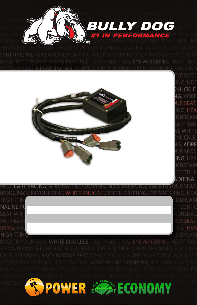
Parts Description:
The product is made up of two dierent parts, the module box,
and cable.
THE MODULE BOX: The module box contains the electronics
that will help the engine to produce more horsepower. It is
very important that this module is mounted away from all
moving or hot parts. The box should be placed in an area
protected from dirt and moisture.
INTRODUCTION
Contents:
1. Rapid Power Module
with Wiring Harness
2. Zip Ties
THE CABLE: This cable allows the Rapid Power Module
to connect to the engine. At the end of the wiring harness are
four plugs, two male and two female plugs. These plugs will
connect directly to the engine and wiring harness requiring no
modication of the engine. The shortest cable is the MAP sensor and the longest one is the ICP Sensor plug
MAP SENSOR PLUGS
Female Plug
Male Plug
THE MODULE BOX
INJECTION CONTROL PRESSURE ICP
SENSOR PLUGS
Male Plug
Female Plug
2
Page 4
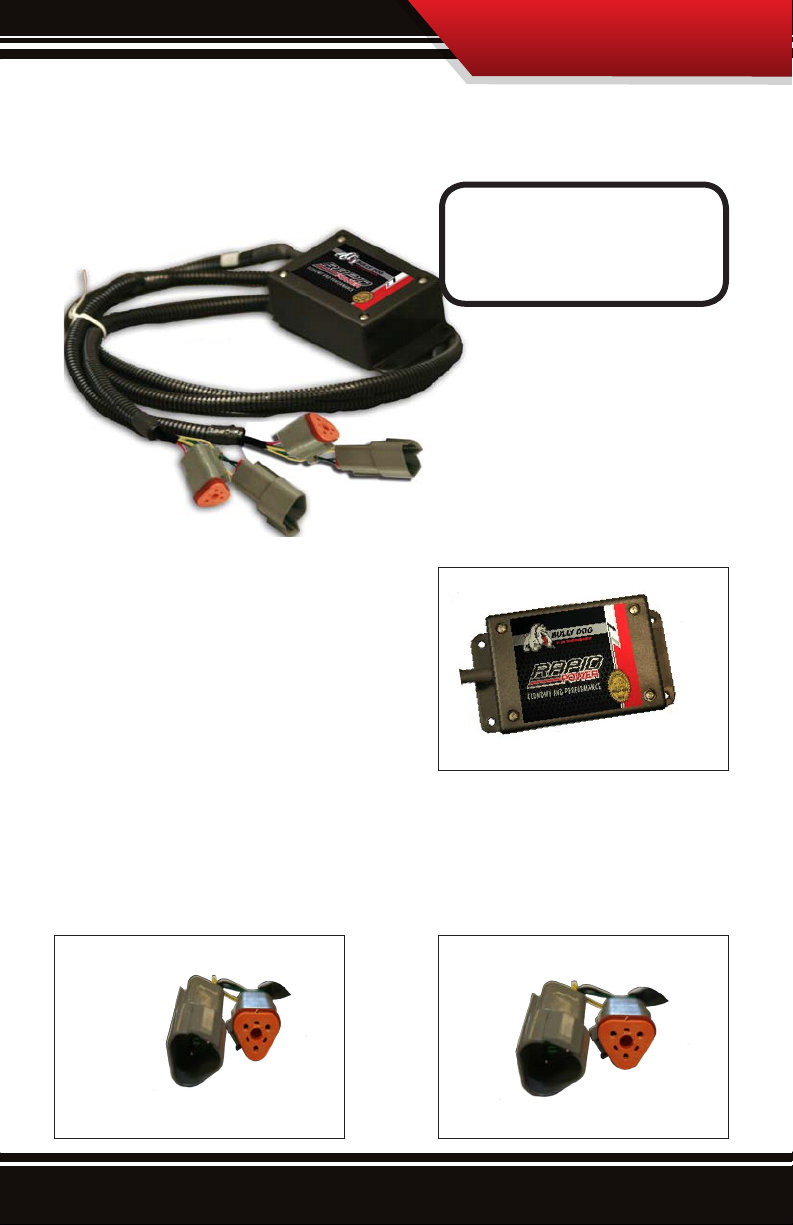
INSTALLATION
Caterpillar Plug Location Diagram 3126
MAP Sensor Juncture
MAP Sensor
Juncture
Injection Control Pressure Sensor
Injection Control Pressure Sensor
3
Page 5
INSTALLATION
L R
F
B
1. Open the engine compartment or remove the engine cover, make sure that the engine is fully accessible so
that plugs can be reached and the module can be mounted to a safe place within the engine bay.
2. Locate the MAP Sensor plug near the back of
the engine on the right side of the engine and
near the rear of the engine. Reference this map
sensor when following step 3.
3. Locate Map sensor plugs: From the map sensor plug follow the wire harness coming out of the Map sensor to
a set of harness plugs. This is the plug set that the Bully Dog Map sensor plugs will intersect. Disconnect those
map sensor plugs from one another.
MAP Sensor
MAP Sensor Plugs
4
Page 6

INSTALLATION
L R
F
B
4. Plug the male OEM MAP sensor plug into
the female Module MAP sensor plug.
5. Plug the female OEM MAP sensor plug in
the male Module MAP sensor plug.
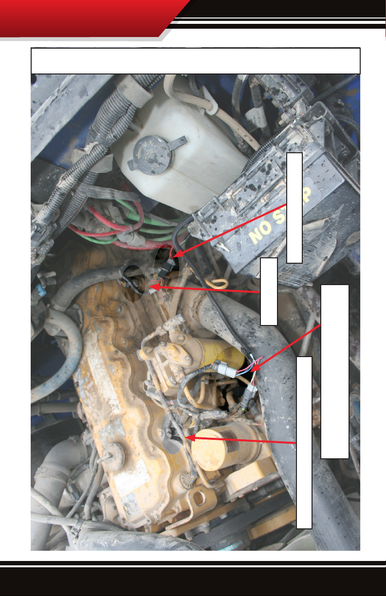
6. Locate the ICP Sensor: like with the MAP sensor plug,
locate the ICP sensor and then follow the connected
wire harness to the plug set and disconnect that plug
set in preparation to tie in the Bully Dog harness. The
Injection Control Pressure sensor is located on the right
side of the engine near the front.
MAP w/ Rapid Power connected
Injection Control Pressure Sensor
5
Injection Control Pressure Sensor
Plug Set
Page 7

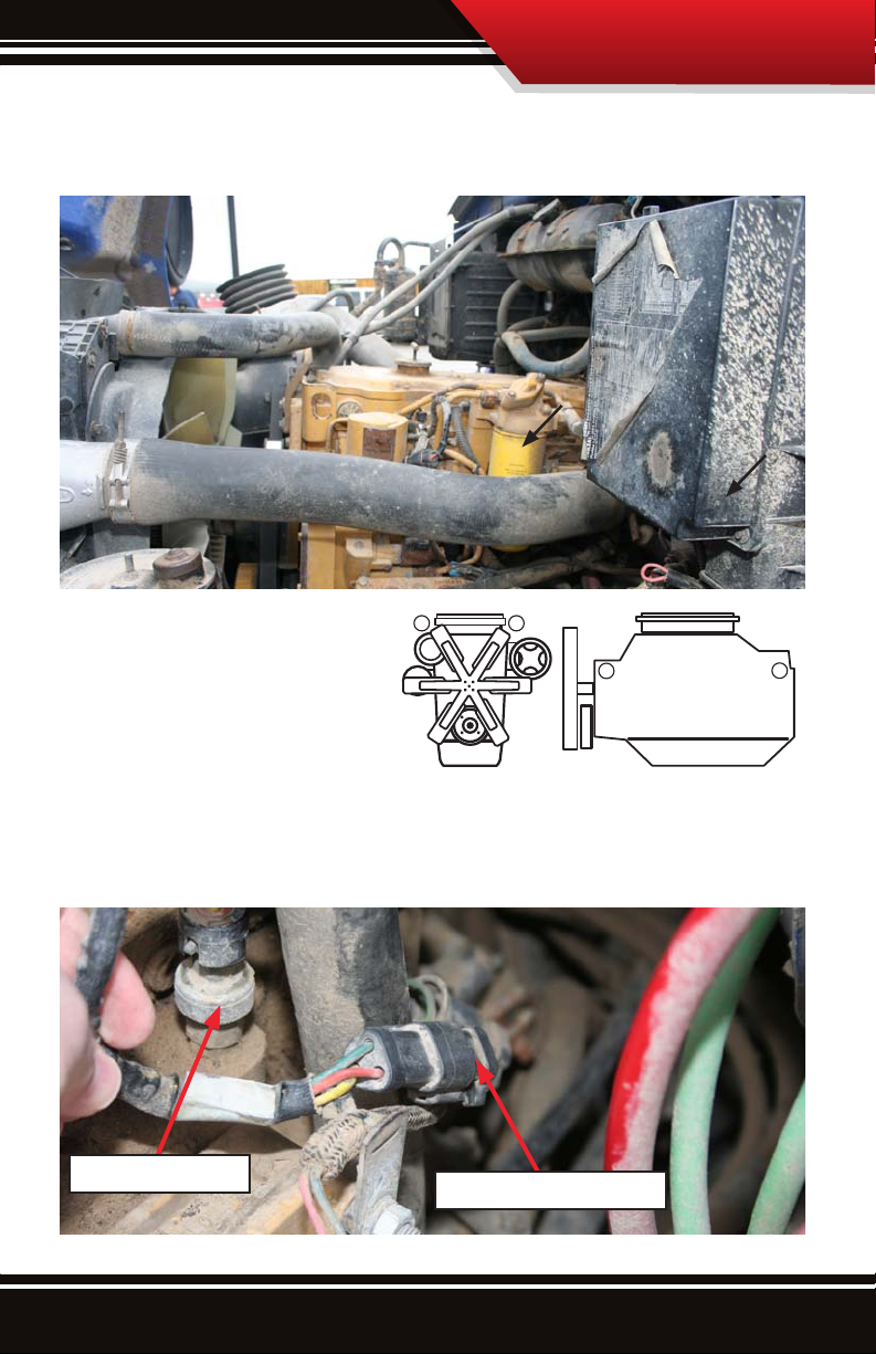
7. Plug the male OEM ICP sensor plug into the female Module ICP sensor plug.
8. Plug the female OEM ICP sensor plug in the male Module ICP sensor plug.
INSTALLATION
9. Mount and secure the Rapid Power module in a location that is away from exteme heat and moving parts. Use
the zip ties included with the package to secure all of the wiring and the module itself.
Warning: Do not remove
module while engine is
running. Shut down machine
and then remove module.
6
Page 8

INSTALLATION
Caterpillar Plug Location Diagram C7
MAP/Boost Sensor
MAP Sensor Juncture
Juncture
Injection Control Pressure Sensor
Injection Control Pressure Sensor
7
Page 9

L R
F
B
INSTALLATION
1. Open the engine compartment or remove the engine cover, make sure that the engine is fully accessible so
that plugs can be reached and the module can be mounted to a safe place within the engine bay.
2. Locate the MAP Sensor plug near the back of
the engine on the right side of the engine and
near the rear of the engine. Reference this map
sensor when following step 3.
3. Locate Map/Boost sensor plugs: The MAP sensor will have a tag on it with the label “Boost,” on it. This is the
spot where the Bully Dog MAP sensor plug set ties into the engine. Unplug the MAP sensor once located.
Unplugged MAP Sensor
MAP Sensor
8
Page 10

INSTALLATION
L R
F
B
4. Plug the male OEM MAP sensor plug into
the female Module MAP sensor plug.
5. Plug the female OEM MAP sensor plug in
the male Module MAP sensor plug.
6. Locate the ICP Sensor: once located then follow the
connected wire harness to the triangle shaped plug set
and disconnect that plug set in preparation to tie in the
Bully Dog harness. The Injection Control Pressure sensor
is located on the right side of the engine near the front.
MAP w/ Rapid Power connected
Injection Control Pressure Sensor
9
Injection Control Pressure Sensor
Plug Set
Page 11

7. Plug the male OEM ICP sensor plug into the female Module ICP sensor plug.
8. Plug the female OEM ICP sensor plug in the male Module ICP sensor plug.
INSTALLATION
9. Mount and secure the Rapid Power module in a location that is away from exteme heat and moving parts. Use
the zip ties included with the package to secure all of the wiring and the module itself.
Warning: Do not remove
module while engine is
running. Shut down machine
and then remove module.
10
Page 12

OPERATING INSTRUCTIONS
ON
1
2
ON
1
2
ON
1
2
ON
1
2
Operating inStrUCtiOnS
INTERNAL POWER LEVEL SWITCH:
The Rapid Power module has three power settings, Stock, Low Power Level or High Power Level. To select dierent power levels remove the cover of the module box, locate the red internal power switch, and set the switch
to the desired power level per illustrations below.
Be sure to securely fasten the module cover after changing the power level. Make sure the cable exits the box
properly in the hole provided.
Stock
Low Power Level
These two positions provide the same power.
High Power Level
Both switches in
the “o” position
indicates Stock
performance
1. After completing the installation of the module, turn the tractor on to test if the module is working. If the
tractor starts then the module is working. If the tractor does not start, check all of the connections on the install
to be sure that they are secure and then attempt to start the tractor again.
2. Adjust performance setting to desired level and enjoy.
First switch in
the “on” position
indicates Low Power
Level.
Second switch in
the “on” Position
indicates High Power
Level.
External Power Switch Female Plug
(External Switch part number 40610)
Both switches in
the “on” Position
indicates High Power
Level.
USB Port
Internal Power Switches
11
Warranty
Page 13

OPERATING INSTRUCTIONS
INTERNET UPGRADES/UPDATE AGENT
IMPORTANT: The information on this page is applicable to all vehicles and tractors.
INTERNET UPDATE The Rapid Power Module is internet updatable. To update remove cover from the mod-
ule and insert a USB cable into the USB port. Ensure that you have downloaded the Update Agent.
The Update Agent will automatically recognize the module and prompt you to update the module if an
update is available. Simply visit Bully Dog’s web site www.bullydog.com/Download_Center.php to
access the Download center to obtain the latest version of the Rapid Power Module.
The most efficient way of keeping up to date with Bully Dog product versions is to use the Update
Agent©. The Update Agent is a software program developed by Bully Dog Technologies specifically to
update Bully Dog products. The Update Agent is easy to use, it can be loaded on any windows based
PC running Windows 2003 or newer. The Update Agent is attainable free of charge at the Bully Dog
download center or by ordering a CD ROM through a Bully Dog distributor.
12
Page 14

INTERNET UPDATE
USB Driver Installation (Windows XP only!)
IMPORTANT: Install the Update Agent prior to plugging in your module .
Your computer will not recognize the Module until the Driver is installed.
1) Remove cover from Rapid Power Module
2) Plug Module into PC using a USB cable (Male A end for PC, Male B end for Module: Same type of
cable as used for most printers)
3) Windows will recognize the Module and attempt to install software.
4) If Windows asks if it can connect to Windows Update to search for the software select NO, not at
this time. Select Next to continue.
5) Select Install Automatically, then press next.
6) Windows will ask you to select the software you would like to install. Select BDT Rapid Power
USB and select next.
13
Page 15

INTERNET UPDATE
7) Windows will warn that this driver is not signed, but select continue anyway!
8) Allow the driver installation to complete and click FINISH
9) The Update Agent should now recognize the device and allow the update to take place. This
could take approximately 30 Seconds or more
14
Page 16

Doc.# 40630-99 V2.0
Check out more of our ADRENALINE PUMPING products!
Downloaders
Intake Systems
Exhaust SystemsTriple Dog GT
®
Free Technical Support at:
866-bullydog (866-285-5936)
See More at: bullydog.com
 Loading...