


INSTRUCTIONS
AND
PARTS MANUAL
UNI-BUG III
THE UNIVERSAL BUG-O
WITH STITCH
Please record your equipment identification information below for future reference. This information can be found on your machine nameplate.
Model Number
Serial Number
Date of Purchase
Whenever you request replacement parts or information on this equipment, always supply the information you have recorded above.
LIT-UNI3-IPM-1114
Bug-O Systems is guided by honesty, integrity and ethics in service to our customers and in all we do.
A DIVISION OF WELD TOOLING CORPORATION
280 TECHNOLOGY DRIVE CANONSBURG, PENNSYLVANIA |
15317-9564 USA |
PHONE: 412-331-1776 http://www.bugo.com FAX: |
412-331- 0383 |

SAFETY
PROTECT YOURSELF AND OTHERS FROM SERIOUS INJURY OR DEATH. KEEP CHILDRENAWAY. BE SURE THATALL INSTALLATION, OPERATION, MAINTENANCE AND REPAIR PROCEDURES ARE PERFORMED ONLY BY QUALIFIED INDIVIDUALS.
ELECTRIC SHOCK can kill.
1)The equipment is not waterproof. Using the unit in a wet environment may result in serious injury. Do not touch equipment when wet or standing in a wet location.
2)The unused connectors have power on them. Always keep the unused connectors covered with the supplied protective panels. Operation of the machine without the protective panels may result in injury.
3)Never open the equipment without first unplugging the power cord or serious injury may result.
4)Verify the customer-supplied power connections are made in accordance with all applicable local and national electrical safety codes. If none exist, use International Electric Code(IEC) 950.
5)Never remove or bypass the equiment power cord ground. Verify the equipment is grounded in accordance with all applicable local and national electrical safety codes. If none exist, use International Electric Code (IEC) 950.
READ INSTRUCTIONS.
Read the instruction manual before installing and using the equipment.
EQUIPMENT DAMAGE
POSSIBLE.
1)Do not plug in the power cord without first verifying the equipment is OFF and the cord input voltage is the same as required by the machine or serious damage may result.
2)Always verity both the pinion and wheels are fully engaged before applying power or equipment damage may occur.
3)Do not leave the equipment unattended.
4)Remove from the work site and store in a safe location when not in use.
FALLING EQUIPMENT can cause serious personal injury and equipment damage.
Faulty or careless user installation is possible. As a result, never stand or walk underneath equipment.
MOVING PARTS can cause serious injury.
1)Never try to stop the pinion from moving except by removing power or by using the STOP control.
2)Do not remove any protective panels, covers or guards and operate equipment.
2

HIGH FREQUENCY WARNINGS
SPECIAL PRECAUTIONS ARE REQUIRED WHEN USING PLASMA, TIG OR ANY WELDING PROCESS THAT USES HIGH FREQUENCY TO STRIKE AN ARC.
WARNING: HIGH FREQUENCY CAN EFFECT MACHINE
OPERATION AND THEREFORE, WELD QUALITY.
Read the precautions below before installing and using the equipment.
PRECAUTIONS:
1)Some plasma or welding cables are strong sources of high frequency interference. NEVER lay a plasma or welding cable across the controls of the machine.
2)Always physically separate the plasma or welding cable leads from the machine cables. For example, the plasma or welding cable leads should NEVER be bundled with a pendant cable or the machine power cord. Maximize the separation between any machine cables and the plasma or welding cables.
3)Strictly follow the grounding procedures specified for the plasma or welding unit. NOTE: Some plasma and welding units produce exceptionally large amounts of high frequency noise. They may require a grounding rod be driven into the earth within six feet (2 meters) of the plasma or welding unit to become compatible with an automatic cutting or welding process.
4)If the high frequency is produced using a spark gap, adjust the points so the gap is as small as possible. The larger the gap, the higher the voltage and the higher the interference.
5)Some plasma or welding units will inject high frequency interference into theAC power line. Use separate power line branches whenever possible to power the plasma or welding source and the machine. Do not plug them into the same outlet box.
6)High frequency noise may enter the machine through the plasma or welding supply remote contactor leads. Some plasma and welding sources can produce noise spikes of up to several thousand volts. These sources are not compatible with automated cutting and welding equipment. It is recommended that the remote contactor leads on these plasma or welding sources not be connected to the machine. An alternate solution is to purchase a separate remote contactor isolation box.
3
|
UNI-BUG III |
||
|
THE UNIVERSAL BUG-O WITH STITCH |
||
|
INSTRUCTIONS AND PARTS MANUAL |
||
|
TABLE OF CONTENTS |
||
PAGE |
|
|
|
5.............. |
Introduction / Setup |
||
6.............. |
Setup Diagram |
||
7.............. |
Operation |
||
8-9........... |
Controls |
||
10............ |
Technical Data / Dimensions UNI-BUG-III |
||
11............ |
Technical Data / Dimensions UNI-BUG III Bulb |
||
12............ |
Technical Data / Dimensions UNI-BUG III “T” |
||
13............ |
Technical Data / Dimensions UNI-BUG III “L” |
||
14............ |
UNI-BUG III Wiring Diagram / Parts List |
||
15............ |
UNI-BUG III Single Gun Welding Kit |
||
16............ |
UNI-BUG III Dual Gun Welding Kit |
||
17............ |
UNI-BUG III Bulb Dual Gun Welding Kit |
||
18-19....... |
UNI-BUG III “T” Dual Gun Welding Kit |
||
20............ |
UNI-BUG III “L” Dual Gun Welding Kit |
||
21............ |
UNI-2400 UNI-BUG III / Exploded View / Parts List |
||
22............ |
UNI-2410 Cover Assembly / Exploded View |
||
23............ |
UNI-2410 Cover Assembly / Parts List |
||
24............ |
UNI-2720 UNI-BUG III Bulb / Exploded View / Parts List |
||
25............ |
UNI-2820 UNI-BUG III “T” / Exploded View / Parts List |
||
26............ |
UNI-2840 UNI-BUG III “T” / Exploded View / Parts List |
||
27............ |
UNI-2920 UNI-BUG “L” / Exploded View / Parts List |
||
28............ |
UNI-1020 Base Assembly / Exploded View |
||
29............ |
UNI-1020 Base Assembly / Parts List |
||
30............ |
UNI-2020 “L” Base Assembly / Exploded View |
||
31............ |
UNI-2020 “L” Base Assembly / Parts List |
||
32............ |
UNI-2120 “T” Base Assembly / Exploded View |
||
33............ |
UNI-2120 “T” Base Assembly / Parts List |
||
34............ |
UNI-2140 “T” Base Assembly / Exploded View |
||
35............ |
UNI-2140 “T” Base Assembly / Parts List |
||
36............ |
UNI-2220 Bulb Base Assembly / Exploded View |
||
37............ |
UNI-2220 Bulb Base Assembly / Parts List |
||
38............ |
UNI-1350 Dual Welding Group / Exploded View / Parts List |
||
39............ |
UNI-1355 Dual Cable Anchor / Exploded View / Parts List |
||
40............ |
BUG-1855 Welding Group / Exploded View / Parts List |
||
41............ |
BUG-1875 Cutting Group / Exploded View / Parts List |
||
42............ |
Troubleshooting Guide |
||
44............ |
Warranty |
||
|
|
|
|
4 |
|
Patents Pending |
|
|
|
|
|
|
|
|
|
INTRODUCTION
The UNI-BUG III is small enough to carry a cutting torch or welding gun into tight work areas or around very tight curves without the use of a track. The built in carrying handle allows for easy mounting and removal at any point along the work piece. The UNI-BUG III can weld or cut both straight line and on an inner radius as small as 6" (152mm). It will travel at speeds of 4-75 ipm
(102-1905 mm/min) with a 50 lb. (22.7 kg) horizontal pulling capacity. The UNI-BUG III is designed to run on the edge of a bar or stiffener up to 2" (51 mm) wide, with a minimum height of 2" (51mm).
SETUP
The UNI-BUG III operates without a track as shown in the set-up diagram. A gear motor turns the two Drive Wheels on one side of the work piece. On the opposite side of the work piece the Idler Wheel Bracket supports four Idler Wheels. An Idler Screw Knob is used to move the Idler Wheel Bracket into the work piece, clamping the work piece between the two Drive Wheels and the four Idler Wheels. The Support Rollers support the machine and tilt it forward for optimal control and traction. This also sets the working direction. The machine is to be tilted in the direction of travel and should be turned around to weld or cut on the opposite side of the work piece. (See Set-Up
Diagram page 6)
1.Loosen the Idler Screw Knob to open the gap between the Idler Wheels and the Drive Wheels. When the gap is large enough, position the machine on the work piece.
2.The machine should be firmly resting on the front and rear Support Rollers and tilted forward, in the direction of travel.
3.Engage the Idler Screw Knob until the Drive Wheels and the Idler Wheels are firmly in contact with the work piece.
4.Adjust the racking group so that the cutting torch, or welding gun is in the proper position. The arc should always be placed below the center of the machine so that the gun or torch can hold the same relative position as the machine moves from a straight to a curved work section.
5
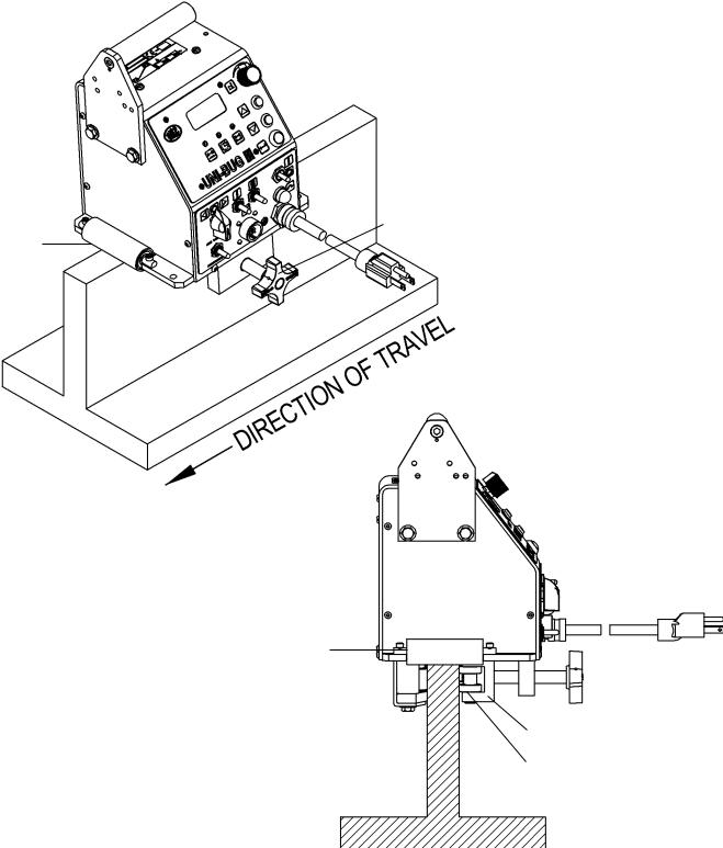
SETUP DIAGRAM
Note: Torch holding devices not shown for clarity.
CARRYING
HANDLE 
IDLER SCREW KNOB
SUPPORT
ROLLER
SUPPORT ROLLERS
DRIVE WHEELS |
|
|
|
|
IDLER SCREW |
|
|
|
|
|
KNOB |
||
|
|
|
|
|
|
|
|
|
|
|
IDLER WHEEL BRACKET |
||
BEAM |
|
|
|
IDLER WHEELS |
||
|
|
|
|
|
|
|
6
OPERATION
Always set the Travel Direction switch to the “Off” position before powering up the machine. If the machine is powered up and the Travel Direction switch is in the left or right position, the controls will be inactive and not be able to be programmed until the Travel Direction switch is turned to the “Off” position.
1.When the machine Power “On/Off switch is in the “On” position the LCD Display shows the set travel speed. The travel speed can be pre-set or adjusted with the Travel Speed Control.
2.Use the Enter button to enter into programming mode, accept parameter values, or toggle to the next setting. Utilizing the Increase and Decrease buttons to adjust the settings. LED lights above the symbols for Skip Length, Crater Fill, and Weld Length will light up to indicate which parameter is being programmed, or edited.
The parameters to be set for stitch welding are:
A. |
Weld Length |
.1'' (.1 cm) increments |
B. |
Crater Fill |
.1 second increments |
C. |
Skip Length |
.1'' (.1 cm) increments |
NOTE: 120 VAC machines are factory set to inches per minute. 42 VAC and 240 VAC machines are factory set to centimeters per minute.
NOTE: Load, heat or application may affect actual travel speed or distance. Minor adjustments to speed or distance settings may be necessary to obtain desired travel.
3.Set the appropriate Weld Contact switches to the “ON” position.
(Welding Operations Only) See machine wiring diagram to wire cable connector for weld contacts.
NOTE: Weld contacts will not close until the travel direction switch is thrown.
The Uni-bug II comes with a power cord only and the amphenol for connecting the contactor to the machine.
Weld Contact - There are two contact cables available: UNI-1085-25 or UNI-1085-50
(sold separately). The other option is to build your own using a heavy lamp type cord and wire it into the 4-pin amphenol. You only need four wires as you connect pin A & B then C & D together to make it work.
4.Turn the Travel Direction switch to the desired direction to begin the welding or cutting operation.
7

CONTROLS
LCD DISPLAY
TRAVEL SPEED
CONTROL
SKIP
LENGTH
|
|
|
|
INCREASE |
CRATER FILL |
|
|
|
BUTTON |
|
WELD 
LENGTH DECREASE BUTTON
ENTER
BUTTON
WELD CONTACT II
WELD CONTACT I
POWER
ON / OFF
TRAVEL DIRECTION
CIRCUIT
BREAKER
SKIP /
CONTINUOUS
8
CONTROLS, CONT’D.
LCD DISPLAY: Displays the programming parameters such as travel speed, skip length, crater fill, and weld length.
TRAVEL SPEED: Used to adjust the travel speed of the machine.
INCREASE BUTTON: Increases the numerical value of the selected parameter.
DECREASE BUTTON: Decreases the numerical value of the selected parameter.
ENTER BUTTON: Enters the set value into memory and toggles you to the next parameter.
SKIP LENGTH: When selected enter the value of the length of the skip distance.
CRATER FILL: When selected enter the value of the crater fill time.
WELD LENGTH: When selected enter the value of the length of the weld.
TRAVEL DIRECTION: Dictates which direction the machine will travel. Must be in the “OFF” position to program parameters.
SKIP / CONTINUOUS: Used to select either the skip or continuous welding operation.
CIRCUIT BREAKER: Provides overload protection for the machine.
POWER ON / OFF: Turns power on and off to the machine.
WELD CONTACT I: If using one welding gun, switch weld contact 1 to the “ON” position.
WELD CONTACT II: If using two welding guns, both weld contact 1 and 2 should be switched to the “ON” position.
9

TECHNICAL DATA / UNI-BUG III
Power Requirement: |
UNI-2400 |
120 |
VAC/50-60/1 |
|
UNI-2402 |
240 |
VAC/50-60/1 |
|
UNI-2404 |
42 |
VAC/50-60/1 |
Speed Range: |
4 ipm to 75 ipm (102 to 1905 mm/min) |
||
Maximum Stiffener Size: |
2'' (50.8 mm) |
|
|
Net Weight: |
18 lb. (8.16 kg) |
|
|
Shipping Weight: |
30 lb. (13.61 kg) |
|
|
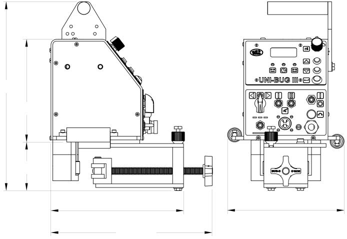
DIMENSIONS
11.5'' (292 mm)
7'' (178 mm)
2'' (51 mm)
2'' |
|
8'' |
|
(51 mm) |
(203 mm) |
6.25'' (159 mm)
7''-9'' (178-229 mm)
10
TECHNICAL DATA: UNI-BUG III BULB
Power Requirement: |
UNI-2720 |
120 |
VAC/50-60/1 |
|
UNI-2722 |
240 |
VAC/50-60/1 |
|
UNI-2724 |
42 |
VAC/50-60/1 |
Speed Range: |
4 ipm to 75 ipm (102 to 1905 mm/min) |
||
Maximum Stiffener Size: |
2'' (50.8 mm) |
|
|
Net Weight: |
13 lbs. (5.9 kg) |
|
|
Shipping Weight: |
40 lbs. (18.14 kg) |
|
|
DIMENSIONS
11.5'' (292 mm)
7.75'' (197 mm)
2'' (51 mm)
2'' (51 mm)
6.88''
(175 mm) 8''
(203 mm)
11
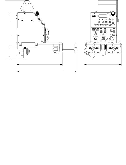
TECHNICAL DATA / UNI-BUG III “T”
Power Requirement: |
UNI-2820 |
120 |
VAC/50-60/1 |
UNI-2840 |
120 |
VAC/50-60/1 |
|
UNI-2822 |
240 |
VAC/50-60/1 |
UNI-2842 |
240 |
VAC/50-60/1 |
|
UNI-2824 |
42 |
VAC/50-60/1 |
UNI-2844 |
42 |
VAC/50-60/1 |
Speed Range:
Net Weight:
DIMENSIONS
13'' (330 mm)
7.75'' (197 mm)
2.65'' (67 mm)
13'' (330 mm)
7.75'' (197 mm)
2.65'' (67 mm)
12
4 ipm to 75 ipm |
Maximum Stiffener Size: 2" (50.8 mm) |
(102 to 1905 mm/min) |
|
13 lbs. (5.9 kg) |
Shipping Weight: 40 lbs. (18.14 kg) |
UNI-2820, UNI-2822 & UNI-2824
|
|
|
10.06'' |
|
8.25'' |
(256 mm) |
|
(210 mm) |
|
|
|
10.67''- 13.37'' (271 - 339.6 mm)
UNI-2840, UNI-2842 & UNI-2844
|
|
|
7.69'' |
8.25'' |
|
(195 mm) |
|
(210 mm) |
8.32''- 10.94'' (211 - 278 mm)
TECHNICAL DATA: UNI-BUG III “L”
Power Requirement: |
UNI-2920 |
120 |
VAC/50-60/1 |
|
UNI-2922 |
240 |
VAC/50-60/1 |
|
UNI-2924 |
42 |
VAC/50-60/1 |
Speed Range: |
4 ipm to 75 ipm (102 to 1905 mm/min) |
||
Maximum Stiffener Size: |
2" (50.8 mm) |
|
|
Net Weight: |
13.5 lbs. (6.12 kg) |
||
Shipping Weight: |
40 lbs. (18.14 kg) |
||
DIMENSIONS
12.89'' (327 mm)
7'' (178 mm)
3.31'' (84 mm)
|
|
|
9'' |
|
8'' |
(229 mm) |
|
(203 mm) |
9.69'' - 15.12'' (229 - 384 mm)
13

UNI-BUG III WIRING DIAGRAM / PARTS LIST
ITEM |
QTY |
PART NO. |
DESCRIPTION |
1 |
1 |
ARM-2279 |
Toggle Switch |
2 |
1 |
BUG-1034 |
Panel Connector |
3* |
1 |
BUG-1393 |
Volt Trap 120 VAC |
3** |
1 |
BUG-1563 |
Volt Trap 240 VAC |
3*** |
1 |
BUG-1393 |
Volt Trap 120 VAC |
4 |
1 |
BUG-1550 |
Gear Motor 150:1 |
5 |
1 |
BUG-1735 |
Speed Control |
6* |
1 |
BUG-2923 |
.7 Amp Circuit Breaker |
6** |
1 |
BUG-2952 |
.5 Amp Circuit Breaker |
6*** |
1 |
BUG-2933 |
2 Amp Circuit Breaker |
7* |
1 |
BUG-9445 |
Power Cord |
7** |
1 |
GOF-3115 |
Power Cord |
7*** |
1 |
BUG-9442 |
Power Cord |
8* |
1 |
BUG-9675 |
Transformer |
8** |
1 |
GOF-3112 |
Transformer |
8*** |
1 |
BUG-1466 |
Transformer |
9 |
1 |
BUG-9677 |
Potentiometer |
10 |
1 |
MUG-1258 |
Rotary Switch |
11 |
1 |
PCB-2400 |
Stitch Board |
12 |
3 |
SWT-7101 |
Toggle Switch |
13 |
1 |
SWT-1111 |
NOR. Open Push Button |
14 |
2 |
SWT-3502 |
NOR. Open Push Button |
15 |
1 |
BUG-1035 |
Cable Connector |
* 120 VAC Part Number
**240 VAC Part Number
***42 VAC Part Number
14
 Loading...