


INSTRUCTIONS
AND
PARTS MANUAL
DC IV
Drive Unit
Please record your equipment identification information below for future reference. This information can be found on your machine nameplate.
Model Number:
Serial Number:
Date of Purchase:
Whenever you request replacement parts or information on this equipment, always supply the information you have recorded above.
LIT-DCIV-IPM-0214
Bug-O Systems is guided by honesty, integrity and ethics in service to our customers and in all we do.
A DIVISION OF WELD TOOLING CORPORATION
280 TECHNOLOGY DRIVE |
CANONSBURG, PENNSYLVANIA, 15317-9564 USA |
PHONE:412-331-1776 |
http://www.bugo.com FAX:412-331-0383 |
SAFETY
PROTECT YOURSELF AND OTHERS FROM SERIOUS INJURY OR DEATH. KEEP CHILDREN AWAY. BE SURE THAT ALL INSTALLATION, OPERATION, MAINTENANCE AND REPAIR PROCEDURES ARE PERFORMED ONLY BY QUALIFIED INDIVIDUALS.
ELECTRIC SHOCK can kill.
1.The equipment is not waterproof. Using the unit in a wet environment may result in serious injury. Do not touch the equipment when wet or standing in a wet location.
2.Never open the equipment without first unplugging the power cord or serious injury may result.
3.Verify the customer-supplied power connections are made in accordance with all applicable local and national electrical safety codes. If none exist, use International Electric Code (IEC) 950.
4.Never remove or bypass the equipment power cord ground. Verity the equipment is grounded in accordance with all applicable local and national electrical safety codes. If none exist, use lnternational Electrical Code (IEC) 950.
READ INSTRUCTIONS
Read the instruction manual before installing and using the equipment.
EQUIPMENT DAMAGE
POSSIBLE.
1.Do not plug in the power cord without first verifying the equipment is OFF and the cord input voltage is the same as required by the machine or serious damage may result.
2. Do not leave the equipment unattended. Remove from the worksite and store in a safe location when not in use.
FALLING EQUIPMENT
can cause serious personal injury and equipment damage.
Faulty or careless user installation is possible. As a result, never stand or walk underneath equipment.
MOVING PARTS can cause serious injury.
1.Never try to stop the pinion from moving except by removing power or by using the STOP control.
2.Do not remove any protective panels, covers or guards and operate equipment.
CAUTION
DO NOT LEAVE EQUIPMENT UNATTENDED
WHEN NOT IN USE!
Remove from work site and store in a safe location.
2

DC IV DRIVE UNIT
INSTRUCTION AND PARTS MANUAL
|
TABLE OF CONTENTS |
PAGE |
|
4........... |
INTRODUCTION |
5........... |
TECHNICAL DATA |
6 .......... |
EXPLODED VIEW / BUG-5100-_ BG DC IV DRIVE UNIT |
7 .......... |
PARTS LIST / BUG-5100-_ BG DC IV DRIVE UNIT |
8 .......... |
WIRING DIAGRAM / DC IV DRIVE UNIT |
8........... |
ELECTRICAL COMPONENT CHART |
9........... |
CARRIAGES FOR DC IV DRIVE UNITS |
10-11.... |
DETAILED SETUP |
12......... |
OPTIONS FOR DC IV DRIVE UNITS |
13......... |
ALUMINUM RIGID RAIL / “ARR” |
14......... |
FLEX RAIL |
15......... |
STANDARD MAGNET ASSEMBLIES |
16......... |
VACUUM SUPPORT KIT |
17......... |
ARV-1036 INTERMEDIATE VAC SUPPORT BAR |
18......... |
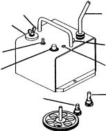
VACUUM PUMP / EXPLODED VIEW |
19......... |
VACUUM PUMP / PARTS LIST |
20......... |
TROUBLESHOOTING GUIDE |
21......... |
WARRANTY |
THIS PRODUCT IS COVERED BY ONE OR MORE PATENTS WORLD WIDE.
3
INTRODUCTION
The DC-IV Drive Unit is the basic drive for many BUG-0 SYSTEMS machines. This drive unit mounts on BUG-0 carriages designed for DC drives. The DC-IV is a positive rack and pinion drive with a wide range solid state speed control. Once mounted on a carriage, the drive unit will run in any position using Aluminum Rigid Rail, Aluminum Flex Rail or Bent Rigid Rail [with a minimum radius of 10' (3 m)].
FEATURES:
A.Wing Nut 1/4-28
B.Cam Clutch engages and disengages the
C.Power Cord
D.Power Indicator Light
E.Forward-Off-Reverse Switch
F.Infinitely Variable Speed Control
G.Circuit Breaker
H.Factory Installed Pinion provides a high torque, low speed range
J.Alternate Pinion bypasses the bull gear to obtain a low torque, high speed range
B A
E
F
H
C
G
D
J
ASSEMBLY AND OPERATING INSTRUCTIONS
The DC-IV Drive Unit has been factory tested and is ready to be mounted on any standard BUG-O SYSTEMS carriage.
To install the drive unit, screw the cam clutch stud into the carriage. Use the 5/16 x 3/8 socket head shoulder screw provided to attach the DC-IV to the carriage.
Rotate the Cam Knob (B) to move the drive in and out of engagement with the rack.
To lock the drive position, tighten the 1/4-28 Wing Nut (A) provided.
To position the drive unit, loosen the 1/4-28 Wing Nut (A) and turn the Cam Knob (B) far enough to disengage the drive pinion from the rack. Move the carriage to the starting point on the rail. Turn the Cam Knob (B) to engage the drive pinion with the rack. Retighten the 1/4-28 Wing Nut (A) to lock the drive carriage into position.
Two pinion gears are provided. The Factory Installed Pinion (H) engages the bull gear to provide a high torque, low speed range. The user can easily install the Alternate Pinion (J) to bypass the bull gear and obtain a low torque, high speed range.
Once the Power Cord (C) is plugged into the appropriate power source, the Pilot Light (D) will glow. Switch (E) controls the direction of travel, with the center position as “OFF”. Knob (F) controls the speed.
The Circuit Breaker (G) protects the drive unit against overload or electrical faults.
CAUTION: IF THE CIRCUIT BREAKER OPENS, FIND AND CORRECT THE CAUSE OF FAILURE BEFORE RESETTING.
4
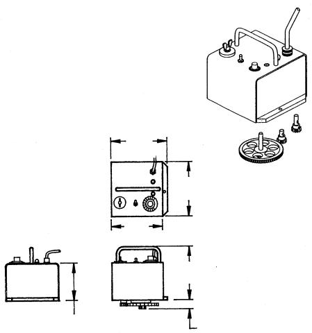
TECHNICAL DATA
Power
Requirements: - 60 watts at rated voltage:
DC IV: BUG-5100-_BG 120 VAC/50-60/1 BUG-5102-_BG 240 VAC/50-60/1 BUG-5104-_BG 42 VAC/50-60/1
Dimensions:
Net Weight:
Shipping Weight:
DIMENSIONS:
7.12"L x 6.75"W x 6.63"H (181 mm x 171 mm x 168 mm)
17 lbs. (7.7 kg)
21 lbs. (9.5 kg)
DC IV
DRIVE UNIT
7.12" (181 mm)
6.75" (171 mm)
6.50" (165 mm)
6.63" (168 mm)
|
|
4.63" (118 mm) |
|
|
|
||||
Drive Load Chart |
|
|
1.12" (28 mm) |
|
|||||
Pinion |
Speed Range |
Continuous |
|
Model Number |
|
||||
Gear |
|
|
Vert. |
Load |
GEAR |
|
|
|
|
Used |
in/min. (mm/min.) |
LBS |
KG |
RATIO |
120/60-60/1 |
240150-60/1 |
42/50-60/1 |
||
Low |
1.5-30 |
(38-750) |
50 |
22 |
|
|
|
|
|
Speed |
50:1 |
BUG-5100-CBG |
BUG-5102-CBG |
BUG-5104-CBG |
|||||
High |
8-160 |
(200-4000) |
3 |
1.4 |
|||||
|
|
|
|
||||||
Speed |
|
|
|
|
|||||
|
|
|
|
|
|
|
|
|
|
Low |
.7-15 |
(19-380) |
75 |
34 |
|
|
|
|
|
Speed |
|
|
|
|
|||||
|
|
|
|
|
100:1 |
BUG-5100-EBG |
BUG-5102-EBG |
BUG-5104-EBG |
|
High |
4-80 |
(100-2000) |
15 |
7 |
|||||
|
|
|
|
||||||
Speed |
|
|
|
|
|||||
|
|
|
|
|
|
|
|
|
|
Low |
.5-10 |
(12-255) |
100 |
45 |
|
|
|
|
|
Speed |
|
|
|
|
|||||
|
|
|
|
|
150:1 |
BUG-5100-FBG |
BUG-5102-FBG |
BUG-5104-FBG |
|
High |
2-50 |
(50-1250) |
30 |
14 |
|||||
|
|
|
|
||||||
Speed |
|
|
|
|
|||||
|
|
|
|
|
|
|
|
|
|
|
|
|
|
|
|
|
|
5 |
|

EXPLODED VIEW / BUG-5100-_BG
2 28
|
7 |
|
6 |
|
8 |
35 |
27 |
24
9 |
|
23 |
|
26 |
36 |
|
|
39 |
1 |
|
|
|
3 |
33
38
22
5 13 |
41 |
18 |
12 |
16
17
34
4 |
14 |
10 |
12
35
15
19
31
37 25
11
29
21
33 40
20
32
30
PARTS LIST / BUG-5100-_BG
DC IV DRIVE UNIT
ITEM |
QTY. |
PART NO. |
DESCRIPTION |
*1 |
1 |
BUG-1393 |
Volt Trap 120 VAC |
*2 |
1 |
BUG-1415 |
Pilot Light 120 VAC |
**3 |
1 |
BUG-1550 |
Gear Motor; (150:1 for BUG-5100-FBG) |
4 |
1 |
BUG-1725 |
Precision Speed Control |
5 |
1 |
BUG-2255 |
Toggle Switch |
*6 |
1 |
BUG-2923 |
Circuit Breaker w/ Reset. 7A |
7 |
1 |
BUG-2924 |
Reset Button Seal |
8 |
1 |
BUG-2988 |
End Plate |
9 |
1 |
BUG-5111 |
Cover |
10 |
1 |
BUG-5112 |
End Plate |
11 |
1 |
BUG-5114 |
Swivel Plate |
12 |
1 |
BUG-5120 |
Cam Clutch Assembly |
|
|
|
(Includes items 13 thru 18) |
13 |
1 |
BUG-2767W |
Wing Nut 1/4-28 |
14 |
1 |
BUG-5113 |
Tube & Cam Assembly |
15 |
1 |
BUG-5116 |
Stud |
16 |
1 |
BUG-5119 |
Knob |
17 |
1 |
BUG-5122 |
Delrin Washer |
18 |
1 |
WAS-0240 |
1/4 Washer |
19 |
4 |
BUG-5121 |
Stand Off |
20 |
1 |
BUG-5128 |
Drive Pinion w/ Long Shaft |
21 |
1 |
BUG-5131 |
Sleeve |
22 |
1 |
BUG-9444 |
Tool Kit |
*23 |
1 |
BUG-9445 |
Power Cord 120 VAC |
24 |
1 |
BUG-9446 |
Cord Grip |
25 |
1 |
BUG-9614 |
Needle Bearing |
*26 |
1 |
BUG-9675 |
Transformer 120 VAC |
27 |
1 |
BUG-9677 |
Potentiometer |
28 |
1 |
BUG-9687 |
Knob |
29 |
1 |
BUG-5126 |
Bar |
30 |
1 |
BUG-5127 |
Drive Pinion w/ Short Shaft |
31 |
1 |
BUG-9012 |
Locking Collar |
32 |
1 |
BUG-9013 |
Gear Assembly |
33 |
2 |
BUG-9635 |
Flange Bearing 3/8 |
34 |
2 |
FAS-0112 |
Pan Hd. Screw 6-32 x 1/4 |
35 |
8 |
FAS-0114 |
Pan Hd. Screw 6-32 x 3/8 |
36 |
7 |
FAS-0124 |
Pan Hd. Screw 8-32 x 3/8 |
37 |
2 |
FAS-0537 |
Soc. Hd. Cap Screw 10-24 x 3/4 |
38 |
1 |
FAS-0654 |
Soc. Hd. Shldr. Screw 5/16 x 3/8 x 1/4-20 |
39 |
3 |
FAS-1320 |
Hex Nut 8-32 |
40 |
4 |
FAS-2824 |
Flt. Hd. Slt. Screw 8-32 x 1 3/4 |
41 |
1 |
GOF-3019 |
Handle w/ Nuts |
*See Electrical Component Chart for 240 VAC and 42 VAC part numbers.
**BUG-1600 Gear Motor: (50:1 for BUG-5100-CBG) BUG-1595 Gear Motor: (100:1 for BUG-5100-EBG)
7
 Loading...