


Modular Drive System

INSTRUCTIONS
AND
PARTS MANUAL
MODULAR DRIVE
SYSTEM
A DIVISION OF WELD TOOLING CORPORATION
280 TECHNOLOGY DRIVE CANONSBURG, PENNSYLVANIA 15317-9564 USA
PHONE: 412-331-1776 http://www.bugo.com FAX: 412-331- 0383
Please record your equipment identication information below for future reference. This information can be
found on your machine nameplate.
Model Number:
Serial Number:
Date of Purchase:
Whenever you request replacement parts or information on this equipment, always supply the information
you have recorded above.
LIT-MDS-IPM-0215
Bug-O Systems is guided by honesty, integrity and
ethics in service to our customers and in all we do.
2
SAFETY
PROTECT YOURSELF AND OTHERS FROM SERIOUS INJURY OR DEATH.
KEEP CHILDREN AWAY. BE SURE THAT ALL INSTALLATION, OPERATION,
MAINTENANCE AND REPAIR PROCEDURES ARE PERFORMED ONLY BY
QUALIFIED INDIVIDUALS.
EQUIPMENT DAMAGE
POSSIBLE.
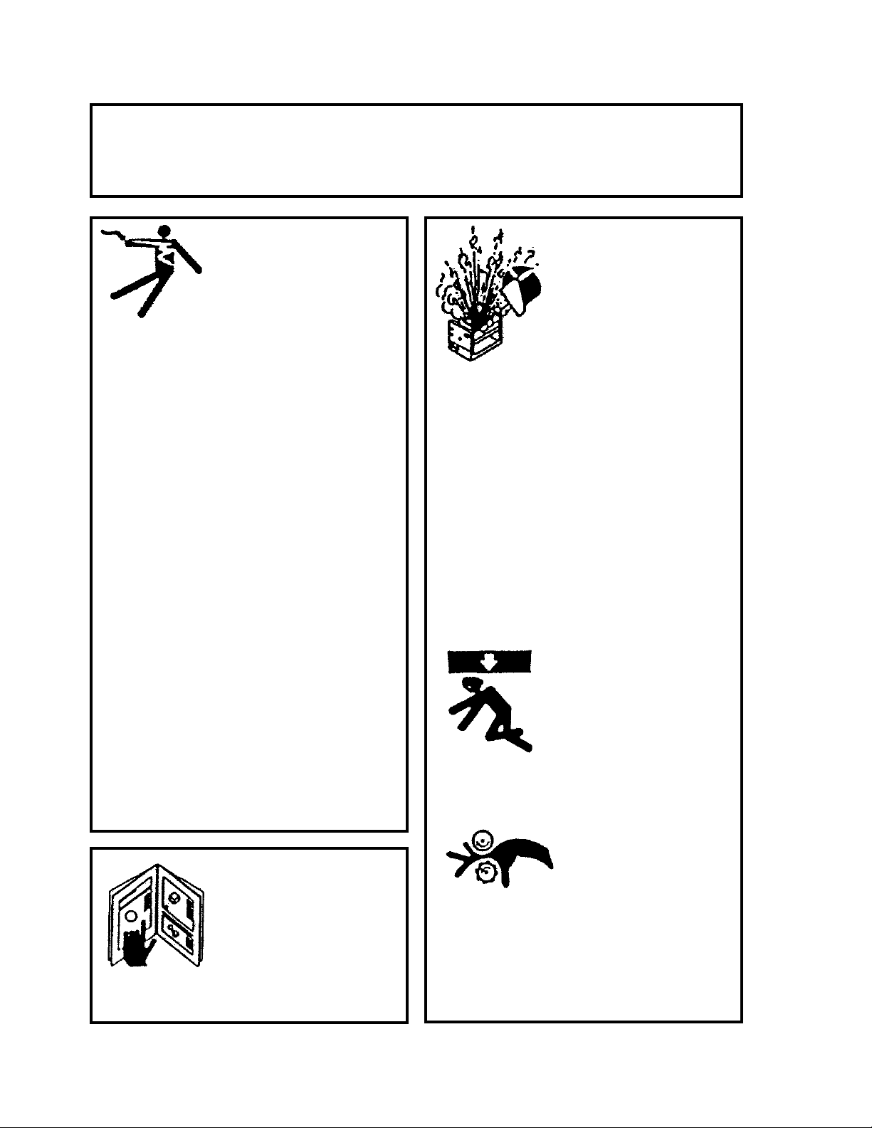
ELECTRIC SHOCK can kill.
1) The equipment is not waterproof.
Using the unit in a wet environ-
ment may result in serious injury.
Do not touch equipment when wet
or standing in a wet location.
2) The unused connectors have
power on them. Always keep the
unused connectors covered with
the supplied protective panels.
Operation of the machine without
the protective panels may result in
injury.
3) Never open the equipment without
rst unplugging the power cord or
serious injury may result.
4) Verify the customer-supplied power
connections are made in accordance
with all applicable local and national
electrical safety codes. If none exist,
use International Electric Code (IEC)
950.
5) Never remove or bypass the equip-
ment power cord ground. Verify the
equipment is grounded in accor-
dance with all applicable local and
national electrical safety codes. If
none exist, use International Electric
Code (IEC) 950.
READ INSTRUCTIONS.
Read the instruction manual before
installing and using the equipment.
1) Do not plug in the power cord without
rst verifying the equipment is OFF
and the cord input voltage is the same
as required by the machine or serious
damage may result.
2) Always verity both the pinion and
wheels are fully engaged before apply-
ing power or equipment damage may
occur.
3) Do not leave the equipment
unattended.
4) Remove from the work site and store in
a safe location when not in use.
1) Never try to stop the pinion from mov-
ing except by removing power or by
using the STOP control.
2) Do not remove any protective panels,
covers or guards and operate equip-
ment.
MOVING PARTS can
cause serious injury.
FALLING EQUIPMENT
can cause serious
personal injury and
equipment damage.
Faulty or careless user installation is
possible. As a result, never stand or
walk underneath equipment.
3
PRECAUTIONS:
1) Some plasma or welding cables are strong sources of high frequency interference.
NEVER lay a plasma or welding cable across the controls of the machine.
2) Always physically separate the plasma or welding cable leads from the machine
cables. For example, the plasma or welding cable leads should NEVER be bundled
with a pendant cable or the machine power cord. Maximize the separation between
any machine cables and the plasma or welding cables.
3) Strictly follow the grounding procedures specied for the plasma or welding unit.
NOTE: Some plasma and welding units produce exceptionally large amounts of high
frequency noise. They may require a grounding rod be driven into the earth within six
feet (2 meters) of the plasma or welding unit to become compatible with an automatic
cutting or welding process.
4) If the high frequency is produced using a spark gap, adjust the points so the gap is as
small as possible. The larger the gap, the higher the voltage and the higher the
interference.
5) Some plasma or welding units will inject high frequency interference into the AC
power line. Use separate power line branches whenever possible to power the
plasma or welding source and the machine. Do not plug them into the same outlet box.
6) High frequency noise may enter the machine through the plasma or welding supply
remote contactor leads. Some plasma and welding sources can produce noise spikes
of up to several thousand volts. These sources are not compatible with automated
cutting and welding equipment. It is recommended that the remote contactor leads on
these plasma or welding sources not be connected to the machine. An alternate
solution is to purchase a separate remote contactor isolation box.
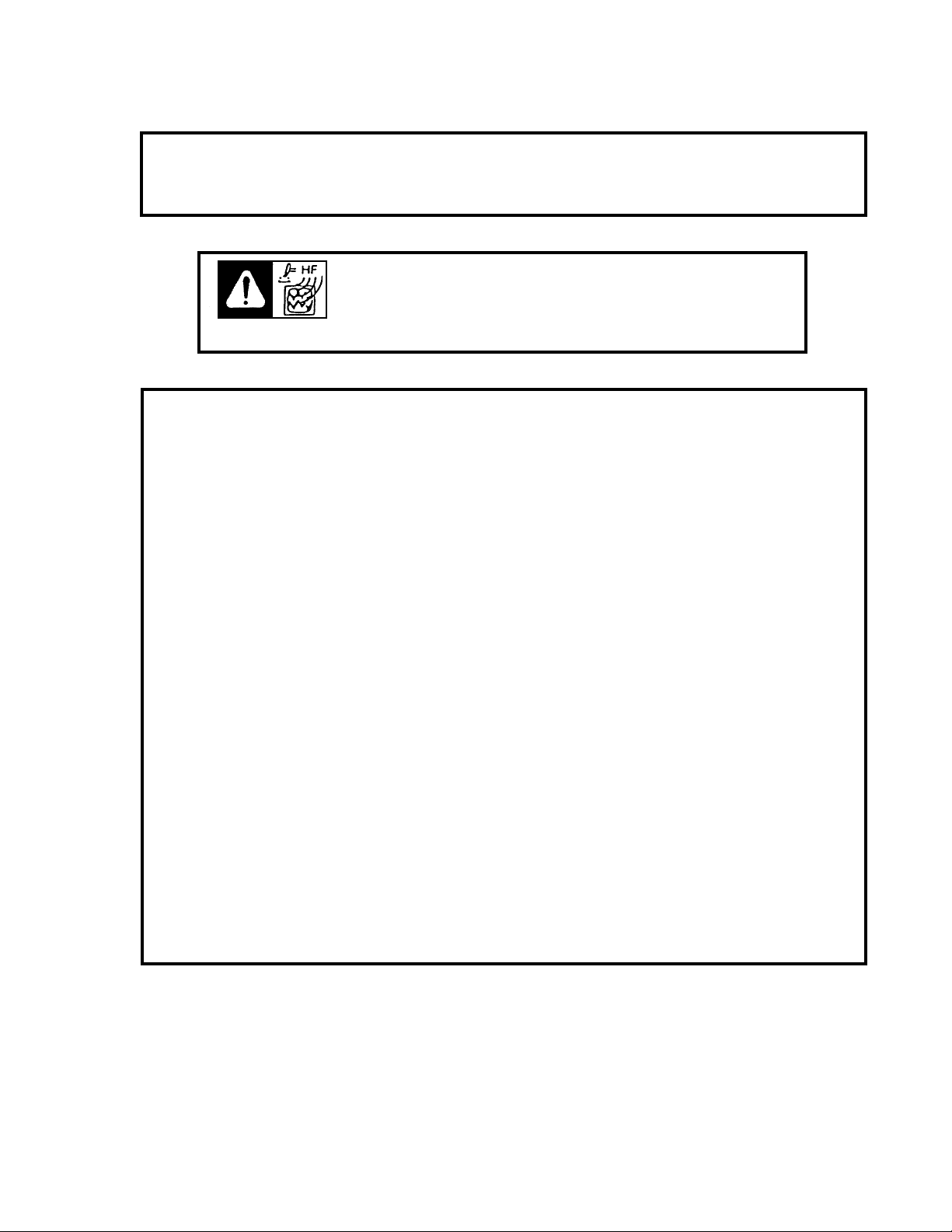
HIGH FREQUENCY WARNINGS
WARNING: HIGH FREQUENCY CAN EFFECT MACHINE
OPERATION AND THEREFORE, WELD QUALITY.
SPECIAL PRECAUTIONS ARE REQUIRED WHEN USING PLASMA,
TIG OR ANY WELDING PROCESS THAT USES HIGH FREQUENCY TO
STRIKE AN ARC.
Read the precautions below before installing and using the equipment.

4
5.............. Introduction / Standard Features
6.............. Additional Features
7.............. Setup
8.............. Master Drive Unit / Technical Data / Dimensions
9 ........... MPD-1000 Master Drive Unit / Exploded View / Parts List
10 ......... Master Drive Unit / Wiring Diagram
11 ......... AC Power Wiring Diagram / Electrical Component Chart
12 ......... Signal Wiring / Parts List
13............ Modules / Technical Data / Dimensions
14 ......... MDS-1002 Straight Module
15-16 ... MDS-1003 Stitch Module
17 ......... MDS-1004 Programmable Module
18-19 ... MDS-1005 / MDS-1005-DIAL / Weaver Control Modules
20 ......... MDS-1005 / MDS-1005-DIAL / Weaver Control Module Replacement Parts
21 ......... Digital Readout Calibration
22............ WPD-1000 Linear Weaver / Introduction / Features
23 ......... Linear Weaver / Technical Data / Dimensions
24-25 ... Linear Weaver / Setup
26 ......... WPD-1100 Linear Weaver / Exploded View
27 ......... WPD-1100 Linear Weaver / Parts List
28............ WPD-2100 Pendulum Weaver II / Introduction / Features
29-30 ... Pendulum Weaver II / Installation / Setup and Alignment
31 ......... Pendulum Weaver II / Technical Data / Dimensions
32 ......... WPD-2100 Pendulum Weaver II / Exploded View / Parts List
33 ......... WPD-2120 Pendulum Weaver II / Electronics / Exploded View / Parts List
34 ......... WPD-2115 Pendulum Gear Box / Exploded View
35............ Weaver Unit / Wiring Diagram
36............ Carriages
37............ Detailed Setup
38............ MDS-1055 Universal Limit Kit
39............ MDS-1060-_ Remote Control Cable
39............ CAS-__ Automatic Height Control
40............ Accessories
41............ Aluminum Rigid Rail
42............ Semi Flex Rail
43............ Hi-Flex Rail
44............ Standard Magnet Assemblies
45-46 ...... Vacuum Support Kit
47-56 ...... Troubleshooting Guide
57............ Warranty
TABLE OF CONTENTS
MODULAR DRIVE SYSTEM
INSTRUCTIONS AND PARTS MANUAL
PAGE

5
The Modular Drive System is the only product in the industry that allows the user to custom congure one
machine for various applications. The system consists of drives, plug-in control modules and carriages
that are easily assembled. The modular design allows the operator to quickly upgrade or recongure the
machine for straight line cutting and welding, stitch welding or weave welding. The system will run in any
position using Aluminum Rigid Rail, Aluminum Semi-Flex Rail [with a minimum radius of 15' (4.57 m)], Bent
Rigid Rail or Hi-Flex Rail [with a minimum radius of 40" (1 m)].
The straight line cutting and welding conguration consists of a carriage, master drive, racking group and
control module. The optional MDS-1060-10 Remote Control Cable can be used to remote the control
module.
A number of straight line control modules are available. The MDS-1002 Straight Line Module provides
simple direction and speed control for continuous cutting or welding. The MDS-1003 Stitch Module provides
a straight line and stitch welding mode with skip time, weld time and crater/puddle buildup time. The MDS-
1004 Programmable Stitch Module provides digital display of all stitch welding parameters. The MDS-1004
Stitch Module has closed position feedback so all distances are set in inches or mm as opposed to time and
are repeatable. The MDS-1055 Universal Limit Kit adds cycler, stop at limit and rapid return functions to the
MDS-1002 and MDS-1003 modules. The MDS-1004 Programmable Module has built in stop at limit and
rapid return modes. For more features, see the appropriate pages on each of the modules.
The Master Drive is rated at 60 lbs (27 kg) vertical load. (International Robotics Standards Rating)** The
machine is equipped with overload protection.
STANDARD FEATURES
The Master Drive Unit incorporates the following standard internal features:
• High torque, low inertia motor for precise stops and starts.
• Dedicated fail-safe brake with three times the stopping and holding power of the motor.
• Motor overload protection which turns off the motor and engages the brake when excessive load is
placed on the machine.
• Closed loop speed control for adjustable and repeatable control of critical welding or cutting parameters.
• Closed loop position control to prevent position creep when the machine stops to perform an operation
such as crater ll at the end of a stitch weld.
**The International Robotics Standards Rating requires a minimum of 2:1 continuous-duty safety margin on
all power train and electronics components.
INTRODUCTION
6
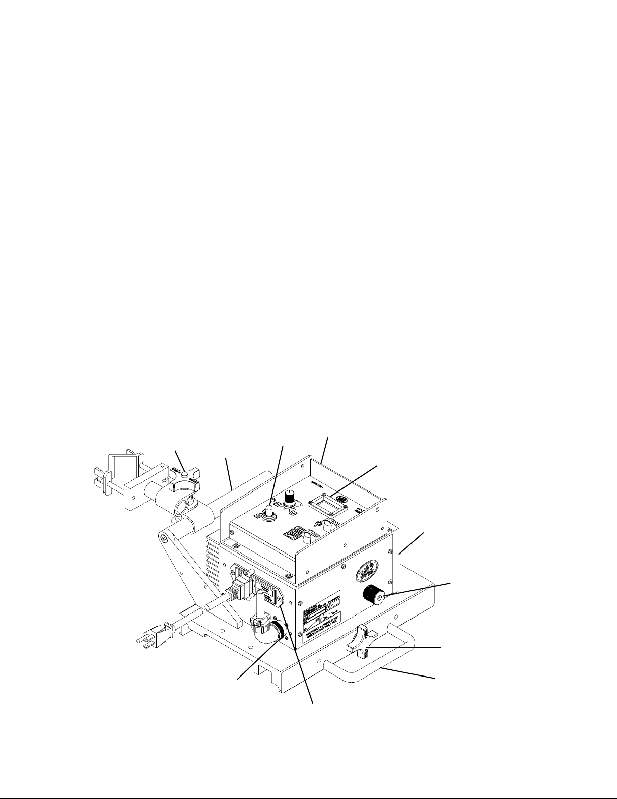
1. Control Module that is easily remoted or changed.
2. Master Power Drive Module that is recongurable by the user, for different applications, by
adding or changing mating modules and accessories.
3. Clutch, to enable rapid manual repositioning of the carriage anywhere on the track.
4. Wheel engagement knob, which enables placement of the releasable carriage anywhere on
the track.
5. Optional cable mounting bar with anchor clamp to keep the welding cables and contact wires
away from the work surface.
6. Contactor ON/OFF switch.
7. Power Entry Box with:
a) Input Power Fuse
b) Machine ON/OFF Switch
c) Power Cord Mating Connector
8. Standard Carrying Handle.
9. Digital speed readout for more repeatable welding/cutting.
10. Optional Carrying Handle and Mounting Bar.
11. Remote Weld Contactor Receptacle.
ADDITIONAL FEATURES
5
10
6
1
9
2
3
4
8
11
7
7
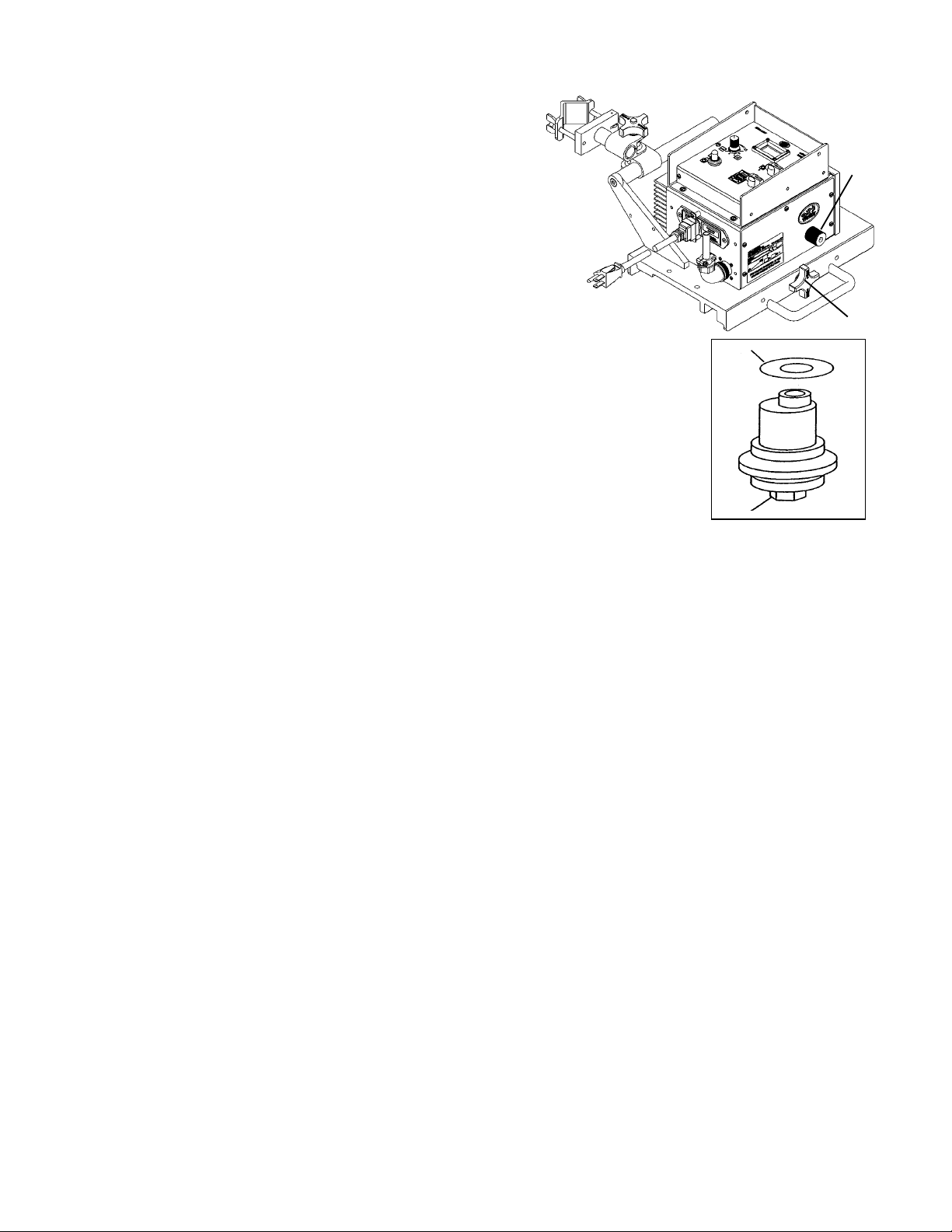
1) WHEEL ADJUSTMENT AND ALIGNMENT
Always check for proper carriage wheel adjustment before
using the machine. Turn the wheel engagement knob (A)
on the side of the carriage until the wheels are fully moved
towards the center of the carriage (engaged). Then rotate
the master drive clutch knob (B) fully counter clockwise to
disengage the drive pinion. Slide the carriage onto the end of
a track. The wheels should slide into the track V-grooves and
the carriage will move smoothly along the track if the wheels
are properly aligned.
The wheels along one side of the carriage have stainless steel shim wash-
ers (C) underneath. These wheels are adjustable. Readjust these wheels (if
necessary) by rotating the hex bolt (D) with a 1/2" wrench.
Grasp the sides of the carriage. The wheels are too loose if it is possible to
move the carriage from side to side or up and down. Use a nger to keep one
of the adjustable wheels from rotating as the carriage is manually pushed
along the track. The wheels are adjusted too tight if rm nger pressure is not
enough to prevent wheel rotation. Repeat the process for the other adjustable
wheel.
2) POSITIONING THE MACHINE ON THE TRACK
Position the rail using magnet plates or vacuum cups. Wipe the track grooves free of weld splatter and other
debris. This will prevent binding and premature rail and wheel wear. Lubricate the rack using a dry spray, if
desired, for extended track life.
Turn the wheel engagement knob (A) on the side of the carriage fully counter clockwise to disengage the
wheels. Then rotate the Master Drive clutch knob (B) fully counter clockwise to disengage the drive pinion.
The carriage can now be placed anywhere on the track. Turn the wheel engagement knob (A) clockwise
to engage the wheels rmly in the V-grooves. Verify all four wheels are in the grooves. Manually move the
carriage along the track to verify the motion is smooth and the wheel alignment is correct. Rotate the Master
Drive clutch knob (B) fully clockwise while gently rocking the machine forward and backward to fully engage
the drive pinion. The rocking motion is necessary to help insure proper gear mesh.
SETUP
C
D
B
A
3) REMOTE CONTACTOR WIRING
Connect the remote weld contactor to the welding source as shown below:
Pins A and B ................. connection for Output #1
Pins C and D ................ connection for Output #2
5) MACHINE OPERATION
Turn the main power ON at the power entry box. Set parameters on control module in use.
4) GUN AND TORCH SETUP
For welding, insert the welding gun into the all-position clamp on the rack. Adjust the clamp, the clamp block
and the rack to position the gun for welding. Connect the weld contactor connector to the rear of the main
drive unit. Route the welding cable and weld contactor wires through the cable anchor clamp.
For cutting, insert the cutting torch into the torchholder on the rack. Adjust the torchholder, the clamp block
and the rack to position the torch for cutting. Connect the hose assembly to the manifold and the cutting
torch. The manifold acts as a strain relief on the supply hoses as well as a quick shut-off valve for the gases.
Once the torch valves are adjusted, the manifold eliminates the need for continuous adjustments and keeps
the supply lines from dragging the torch out of position.
8
CAUTION: The Speed Control Card in the Master Drive is NOT interchangeable
with the speed card in the Linear or Pendulum Weavers.
Power Requirements:
Part Number Voltage / Hz Amps
MPD-1000 120 VAC/50-60 Hz 2A
MPD-1002 240 VAC/50-60 Hz 3A
MPD-1004 42 VAC/50-60 Hz 6A
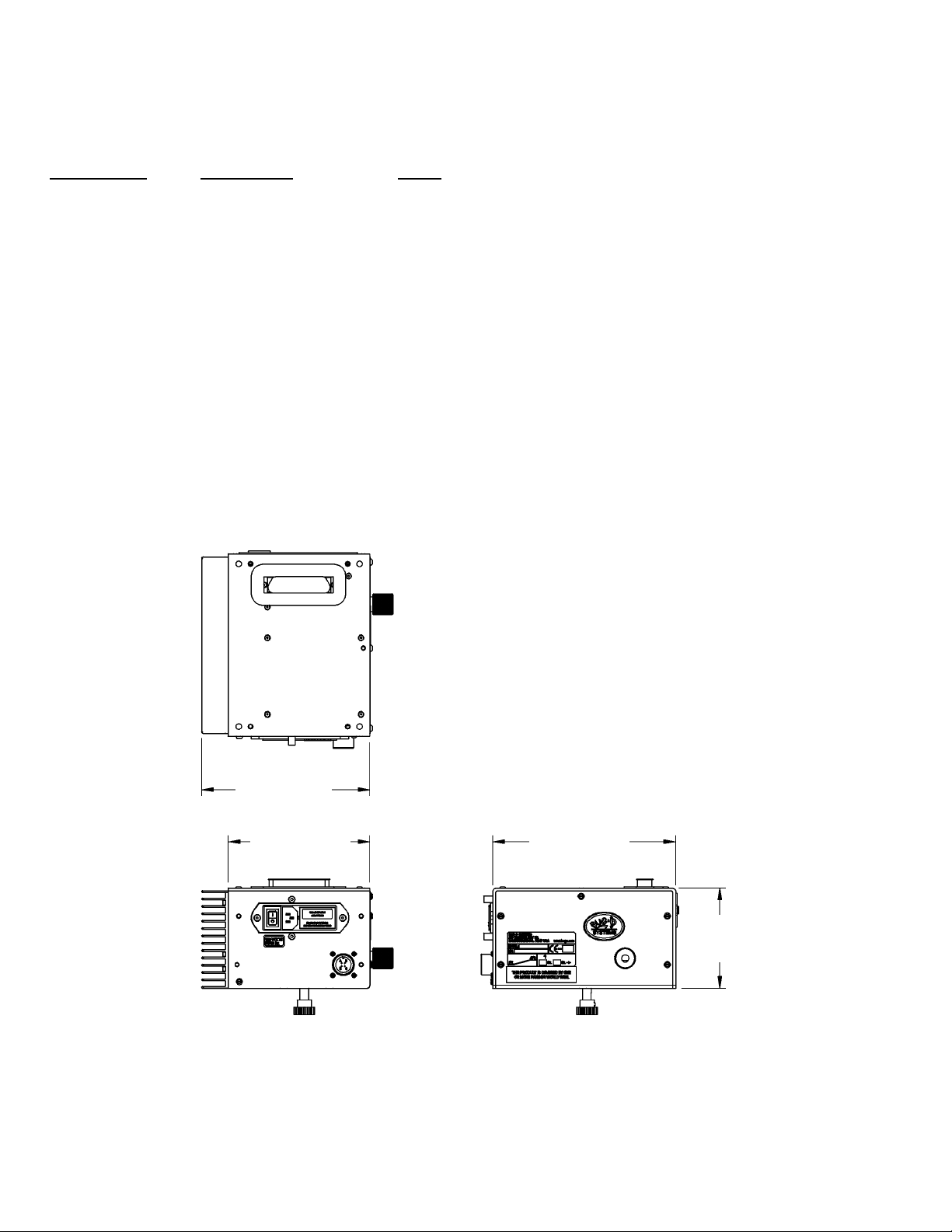
Dimensions: 7.75" L x 6.00" W x 4.25" H
(197 x 152 x 108 mm)
Load Capacity: Vertical - 60 lbs (27 kg) [International Robotics Standards Rating]**
Horizontal - 100 lbs (45 kg)
Speed Range: 2-120 in/min (51-3048 mm/min)
Net Weight: 10 lbs (4.5 kg)
Shipping Weight: 13 lbs (5.9 kg)
MASTER DRIVE UNIT / TECHNICAL DATA
** The Master Drive is rated at 60 lbs (27 kg) vertical load. The International Robotics Standards
Rating requires a minimum of 2:1 continuous-duty safety margin on all power train and electronics
components. The machine is equipped with overload protection.
DIMENSIONS
7.13
(181 mm)
7.75
(197 mm)
4.25
(108 mm)
6.00
(152 mm)
9
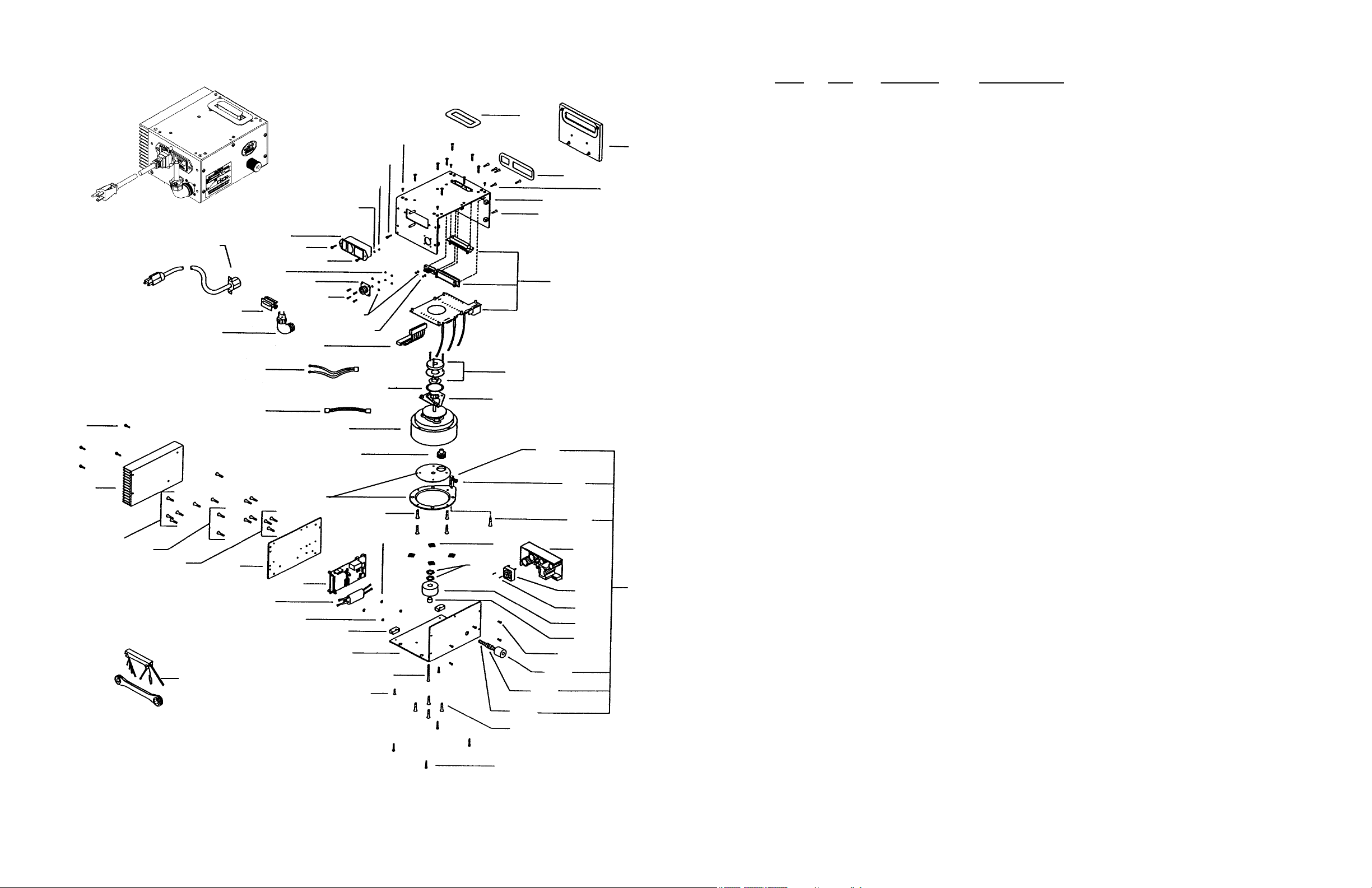
MPD-1000 MASTER DRIVE UNIT / EXPLODED VIEW / PARTS LIST
20
6
15
54
41
11
12
14
1
21
45
46
11
44
10
43
51
55
52
2
39
14
53
4
38
40
30
19
28
13
54
32
35
34
29
50
16
31
25
5
47
18
6
33
36
37
13
11
17
26
27
15
24
49
22
9
10
3
11
23
7
48
42
8
ITEM QTY PART NO. DESCRIPTION
1 1 BUG-1034 Panel Connector, 4-T, Male
2 1 WPD-1013 Rubber Ring Gasket
3 1 BUG-9444 Tool Kit
4 4 FAS-0104 Pan Hd Screw 4-40 x 318 Lg
5 2 FAS-0107 Pan Hd Screw 4-40 x 3/4 Lg
6 6 FAS-0114 Pan Hd Screw 6-32 x 3/8 Lg
7 4 FAS-0504 Soc Hd Cap Scr 4-40 x 3/8 Lg
8 4 FAS-0557 Soc Hd Cap Scr 1/4-20 x 3/4 Lg
9 3 FAS-0902 Fit Hd Soc Scr 4-40 x 1/4 Lg
10 19 FAS-0905 Fit Hd Soc Scr 4-40 x 1/2 Lg
11 11 FAS-0914 Fit Hd Soc Scr 6-32 x 3/8 Lg
12 1 FAS-0915 Fit Hd Soc Scr 6-32 x 1/2 Lg
13 8 FAS-0923 Fit Hd Soc Scr 8-32 x 5/16 Lg
14 6 FAS-1305 Hex Nut 4-40
15 3 FAS-1310 Hex Nut 6-32
16 2 FAS-1325 Hex Nut 8-32 Nylon
17 1 FAS-2823 Fit Hd Sit Scr 8-32 x 1 1/2 Lg
18 1 GOF-3012 Spacer 1/2 OD x 5/16 Lg
19 1 GOF-3014 Pinion
20 4 MDS-1019 Snap Rivet, Black
*21 1 BUG-9454 V-Lock Cord 120VAC
22 1 MPD-1006 Side Panel
23 1 MPD-1007 Heat Sink
24 1 MPD-1008 Filter
25 1 MPD-1009 Fan Assembly
26 1 MPD-1011 Base Panel
27 2 MPD-1012 Mounting Block
28 1 MPD-1090 Matched Clutch Plts
**29 1 BUG-2593 Glide Flat
30 1 MPD-1015 Gear Motor (60:1)
31 1 MPD-1016 Clutch Assembly (Includes items 32 through 37)
32 1 BUG-1216 Ball Joint
33 1 BUG-1857 Knob
34 1 FAS-0945 Fit Hd Soc Scr 10-32 x 1/2 Lg
35 1 FAS-1341 Hex Jam Nut 10-32
36 2 FAS-1390 Hex Nut 3/8-16
37 1 MPD-1017 3/8-16 Threaded Stud
38 1 MPD-1018 Wiring Harness-Speed Board to Motor
39 1 MPD-1019 Wiring Harness-Interconnect to Speed Bd/Control
40 1 MPD-1020 Wiring Harness-Interconnect to Speed Bd/Power
41 1 MPD-1025 Power Entry Module
* 42 1 MPD-1067 Fuse 6A
43 1 MPD-1029 Connector Cover Plate
44 1 MPD-1031 Cover Panel (Includes item #20)
45 1 MPD-1038 Gasket for 50-Pin Connector
46 1 MPD-1039 Gasket for 50-Pin/3-Pin Connector
47 1 MPD-1042 Inductor, Potted-with Connectors
48 1 MUG-1617 Cable Connector, 4-T, Female, Elbow
*49 1 PCB-1000 Speed Board
* 50 1 PCB-1005-120 Power Supply Assembly 165W 120VAC
51 1 PCB-1010 Interconnect Board
52 1 PCB-1012 Position Card
53 6 WAS-0201 #4 Internal Star Lockwasher
54 3 WAS-0211 #6 Internal Star Lockwasher
55 1 WPD-1012 Brake Assembly
* See Electrical Component Chart for 240 VAC and 42 VAC Part Numbers
**Included in Item 28.
CAUTION: The Speed Control Card in the Master Drive is NOT interchangeable with the speed card in the Linear or Pendulum Weavers.

10
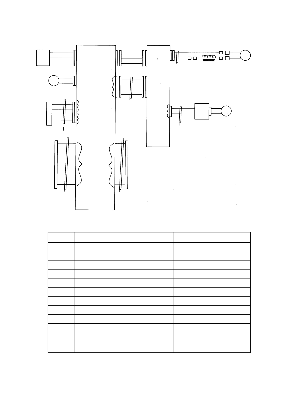
MASTER DRIVE WIRING DIAGRAM MPD-1000/ MPD-1002/ MPD-1004
NOTES:
Encoder card and brake are mounted on the motor.
18 pin connectors are not wired 1:1.
The Connector on one end is ipped.
For example, Pin 1 goes to connector 18.
Most signals on the 50 pin connector come in one 50 pin connector
and exit on the other 50 pin connector.
Pinouts for connectors can be determined from screen print.
120V AND 240V WIRING ONLY
SEE FIGURE 1 FOR 42V WIRING

11
AC POWER WIRING DIAGRAM
PEM
BLK
RFI
RED
GRN
GRN
PC
J1
AC
POWER
OUT
BLK
RED
RED BLK
115 VAC
&
240 VAC
BLK
RED
42 VAC
BLK BLU
RED
BLU
PS PS
BLU
DC OUT
DC OUT
ELECTRICAL COMPONENT CHART
MPD-1000 MPD-1002 MPD-1004
ITEM DESCRIPTION 120 VAC 240 VAC 42 VAC
F1,F2* Fuses (2) MPD-1067 6A (2) MPD-1067 6A (2) MPD-1067 6A
PC Power Cord MPD-1030 MPD-1032 MPD-1034
PS Power Supply PCB-1005-120 PCB-1005-240 PCB-1005-42
J1 Connector w/Pins MPD-1021 MPD-1021 MPD-1021
PEM Power Entry Module MPD-1025 MPD-1025 MPD-1025
RFI Filter Module MPD-1008 MPD-1008 MPD-1008
PART NO.
FUSE BOX
F1
*F2
*F2 replaced with bus wire on 120 VAC
12
SIGNAL WIRING
PS
WHT/RED
WHT/BLK
WHT/OR
WHT/RED
WHT/BLK
WHT/OR
+ 15 V
GND
- 15 V
+ 15 V
GND
- 15 V
F
RED
BLK
CONTACT
A
PUR
PUR
YEL
YEL
A
B
C
D
1
2
3
4
CI
CONTACT
B
MOTOR
OUT
CK
CHOKE
GEAR
MOTOR
M
RED
BLK
INPUTS
OUTPUTS
FROM
CONTROL
MODULE
50 LINE
RIBBON
INTERCONNECT
PCB 1
50 LINE
RIBBON
TO
OSCILLATOR
OR
ACCESSORIES
POSITION
IN AND
BRAKE
OUT
SPEED
CONTROL
PCB 2
18 LINE
C3
C4
PCB 3
10 LINE
RIBBON
B
POSITION
BRAKE
FAN +
FAN -
SPEED
CARD
SIGNALS
C2
ITEM DESCRIPTION PART NO.
B Brake Assembly WPD-1012
Cl Contactor Cable Assembly MPD-1036
C2 DC Power Cable Assembly MPD-1020
C3 Speed Card Cable Assembly MPD-1019
C4 Motor Wiring MPD-1018
CK Inductor Pot Assembly (Choke) MPD-1042
F Fan Assembly MPD-1009
M Gear Motor MPD-1015
PCB1 Interconnect Card PCB-1010
PCB2 Tractor Speed Card PCB-1000
PCB3 Position Sensor Card PCB-1012
PS Power Supply (see AC Wiring Diagram)
PARTS LIST
13
MDS-1002 STRAIGHT LINE MODULE
MDS-1003 STITCH MODULE
MDS-1004 PROGRAMMABLE MODULE
MDS-1005 WEAVER CONTROL MODULE
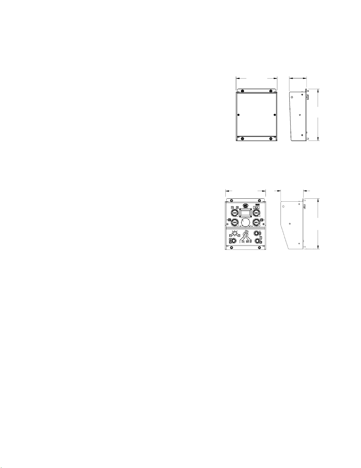
Dimensions: 7.50" L x 6.00" W x 2.50" H
(191 x 152 x 64 mm)
Net Weight: 1.75 lbs (0.8 kg)
Shipping Weight: 3.0 lbs (1.4 kg)
MODULES / TECHNICAL DATA
DIMENSIONS
2.50"
(64 mm)
MDS-1002
MDS-1003
MDS-1004
MDS-1005
6.00"
(152 mm)
7.50"
(191 mm)
6.00"
(152 mm)
3.38"
(86 mm)
7.50"
(191 mm)
MDS-1005-DIAL WEAVER CONTROL MODULE
Dimensions: 7.50" L x 6.00" W x 3.38" H
(191 x 152 x 86 mm)
Net Weight: 3 lbs (1.4 kg)
Shipping Weight: 8 lbs ( 3.63 kg)
Dial Weaver Control Module
14
SPEED CONTROL: Sets the tractor speed from 2-120 in/min (5.1-304.8 cm/min).
CARRIAGE TRAVEL SWITCH: Provides FORWARD/STOP/REVERSE direction control.
Stop at limit in direction of travel & Cycle between limits can be controlled
with the installation of the MDS-1055 Universal Limit Kit. (Ref to pg. 38)
DIGITAL READOUT: The display is dual function.
a) PRESET SPEED - Displayed when the CARRIAGE TRAVEL SWITCH is OFF or motion
is halted by a motor overload condition.
b) MEASURED SPEED - Displayed when power is applied to the motor.
(This will be the same as the Preset Speed.)
Factory settings of 120 Volt machines are set to in/min, 240 and 42 Volt machines are set cm/min.
WELD CONTACT: Opens/closes a pair of independent 1 Amp contacts (pins A & B and C & D) at the weld
contactor receptacle.
NOTE: A safety interlock will automatically open the weld contacts if the motor overload protection halts ma-
chine motion. Clear the overload by turning the carriage travel switch to OFF. Resetting the overload
fault will not cause the contacts to automatically reclose. Use the weld contact switch to restart the
welder plasma unit after clearing the overload.
REPLACEMENT POTS AND SWITCHES
CARRIAGE TRAVEL:
Switch and Spacer MDS-1112
Black Pointer Knob BUG-9694
SPEED CONTROL:
10 K Ω Pot, 3-3/4 turn PCB-1026
Black Knob MDS-1018
Knob Seal Nut MDS-1046
WELD CONTACT:
Switch and Spacer MDS-1115
Toggle Switch Boot MDS-1047
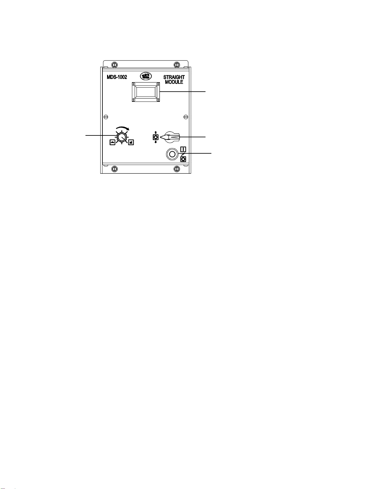
MDS-1002 STRAIGHT MODULE
The MDS-1002 Straight Module provides direction and speed control for continuous cutting or welding.
CARRIAGE TRAVEL SWITCH
WELD CONTACT
(PLASMA)
DIGITAL READOUT
SPEED CONTROL
15
SPEED CONTROL: Sets the tractor weld speed from 2-120 in/min (5.1-304.8 cm/min).
CARRIAGE TRAVEL SWITCH: Provides FORWARD/STOP/REVERSE direction control.
DIGITAL READOUT: The display is dual function.
a) PRESET SPEED - Displayed when the CARRIAGE TRAVEL SWITCH is OFF
or motion is halted by a motor overload condition.
b) MEASURED SPEED - Displayed when power is applied to the motor. (This will
be the same as the Preset Speed.)
Factory settings of 120 Volt machines are set to in/min, 240 and 42 Volt machines are set cm/min.
WELD CONTACT: Opens/closes a pair of independent 1 Amp contacts (pins A & B and C & D) at the
weld contactor receptacle. In STITCH mode, this switch acts as a weld contact en-
able and the stitch module cycles the contacts on and off.
NOTE: A safety interlock will automatically open the weld contacts if the motor overload protection halts
machine motion. Clear the overload by turning the carriage travel switch to OFF. Resetting the
overload fault will not cause the contacts to automatically reclose. Use the weld contact switch to
restart the welder after clearing the overload.
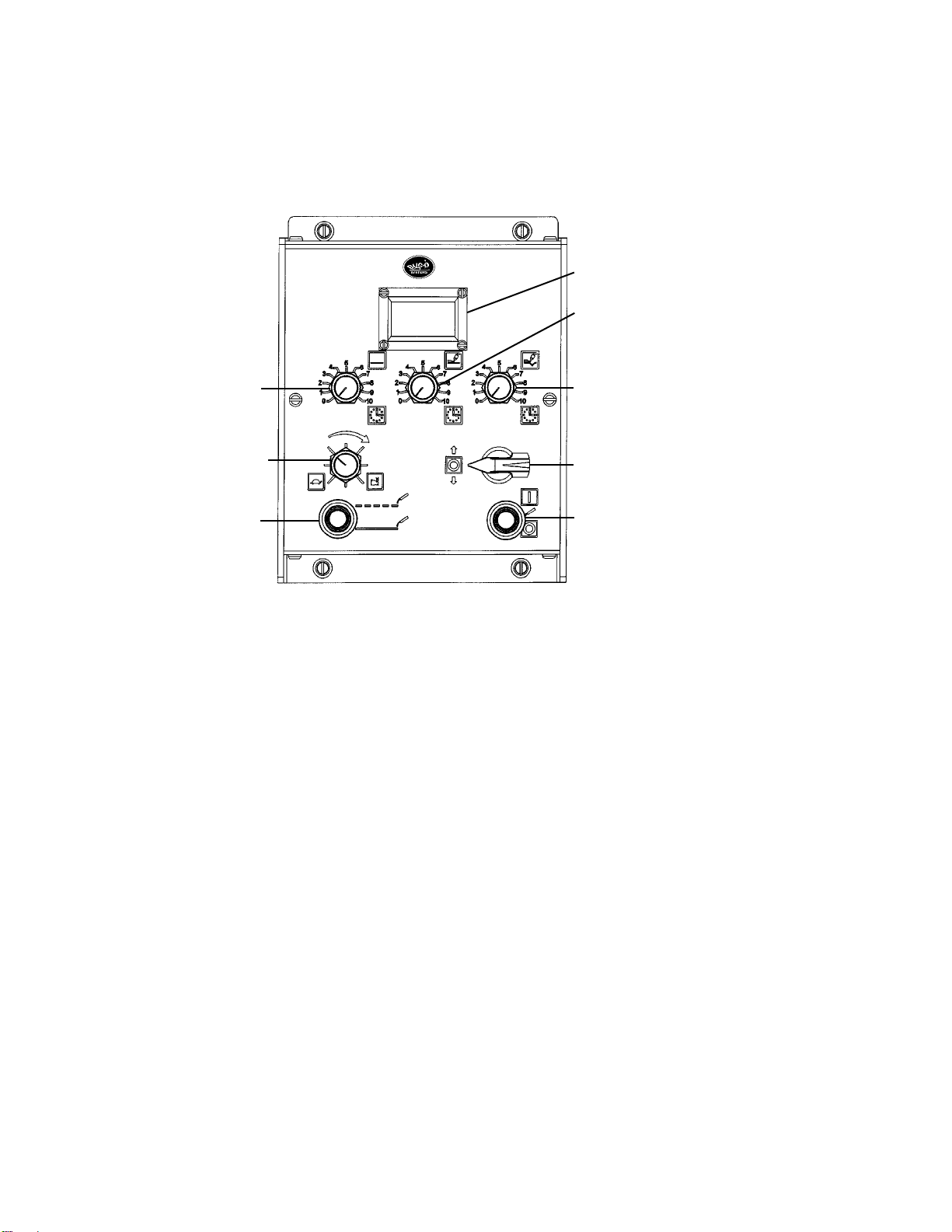
MDS-1003 STITCH MODULE
The MDS-1003 Stitch Module provides direction and speed control for continuous welding and cutting. In
addition, a stitch welding mode is provided, with adjustments for skip time (welder off), weld on time and
puddle buildup/crater ll time.
DIGITAL READOUT
WELD TIME
PUDDLE BUILDUP/CRATER FILL TIME
WELD CONTACT
(PLASMA)
CARRIAGE TRAVEL SWITCH
SKIP TIME
SPEED CONTROL
MODE
MDS-1003
STITCH MODULE

16
STITCH/CONTINUOUS: Selects between cyclic (Stitch) welding and continuous welding or cutting.
a) CONTINUOUS - Selects continuous welding or cutting.
b) STITCH - Selects the cyclic (Stitch) welding mode. This mode consists of four continuously repeated steps.
1) The machine stops moving for the selected time to perform Puddle
Buildup. (PIERCE WHEN PLASMA CUTTING)
2) The machine welds at the selected welding speed for the time selected
using the Weld Time control.
3) The machine stops moving for the selected time to perform Crater Fill.
4) The machine turns off the welder and moves at maximum speed to
where the next weld needs performed. This location is determined by
setting a Skip Time control.
WELD TIME: This control functions only when the mode switch is set to Stitch. Weld time sets a weld
length time from 1-50 seconds. This corresponds to a weld length of approximately 0.03-100 inches (0.8-
2540 mm). NOTE: The operator must manually enable the weld contactor by turning on the Weld Contact
or the welder will never cycle on and off.
SKIP TIME: This control functions only when the mode switch is set to Stitch. Skip time sets how long the
machine travels between welds (0.3-15 seconds). This corresponds with a skip length of approximately 0.6-
30 inches (15-762 mm). The machine always moves between welds at maximum speed.
PUDDLE BUILDUP / CRATER FILL TIME: This control functions only when the mode switch is set to
Stitch. Puddle Buildup/Crater Fill Time sets the time the machine is stopped at the beginning and end of
every weld (0-1.5 sec).
REPLACEMENT POTS AND SWITCHES
WELD CONTACT: CARRIAGE TRAVEL SWITCH:
Switch and Spacer MDS-1116 Switch and Spacer MDS-1112
Toggle Switch Boot MDS-1047 Black Pointer Knob BUG-9694
PUDDLE BUILDUP/CRATER FILL TIME: WELD TIME:
500K Ω Pot, 3/4 turn MDS-1053 500K Ω Pot, 3/4 turn MDS-1053
Black Knob MDS-1018 Black Knob MDS-1018
Knob Seal Nut MDS-1046 Knob Seal Nut MDS-1046
SKIP TIME: SPEED CONTROL:
500K Ω Pot, 3/4 turn MDS-1053 10K Ω Pot, 3 turn PCB-1026
Black Knob MDS-1018 Black Knob MDS-1018
Knob Seal Nut MDS-1046 Shaft Seal Nut MDS-1046
MODE:
Switch and Spacer MDS-1115
Toggle Switch Boot MDS-1047
MDS-1003 STITCH MODULE, CONT’D.
17
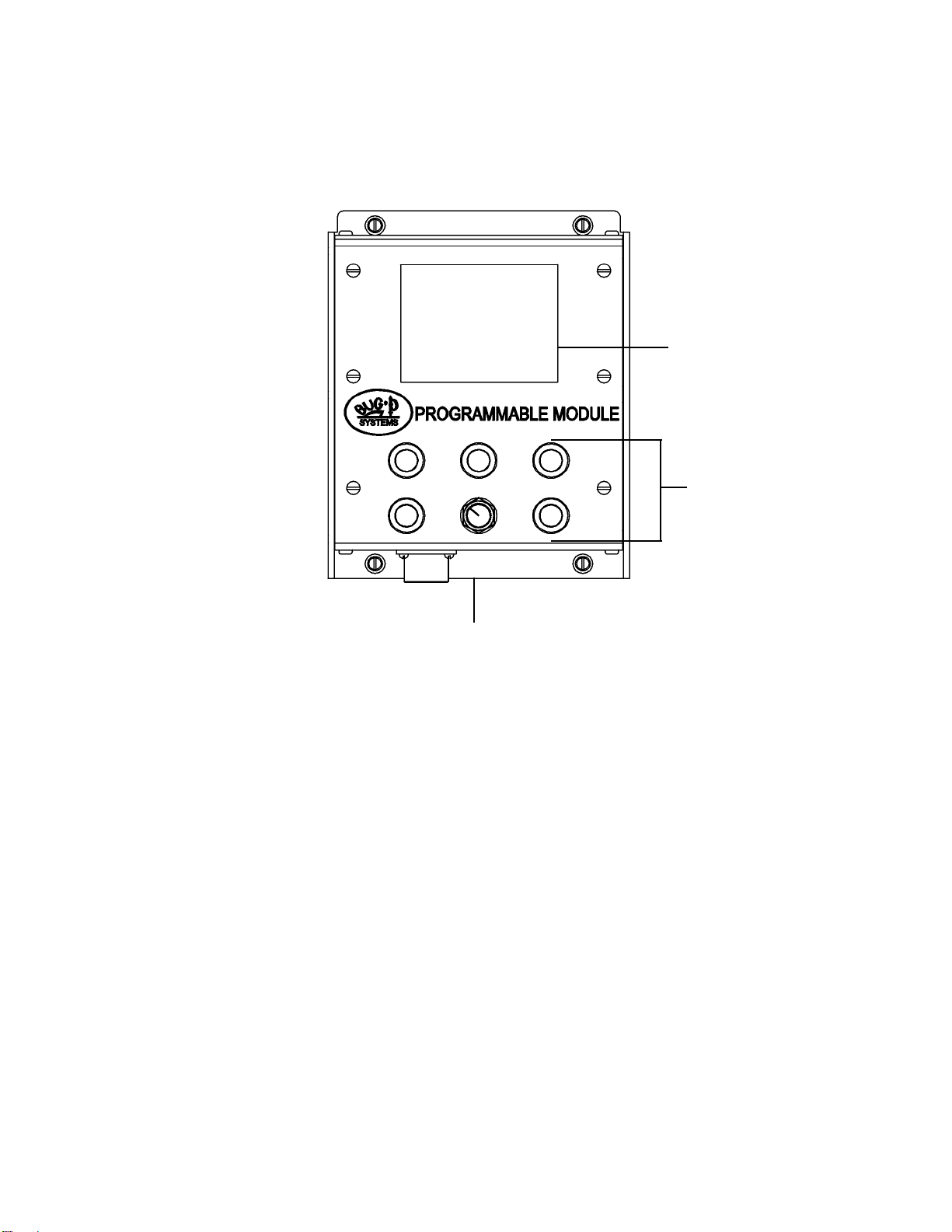
MDS-1004 PROGRAMMABLE MODULE
The MDS-1004 PROGRAMMABLE MODULE provides stitch controls for welding or cutting with the Modular
Drive System. All stitching parameters are set and displayed on a graphic screen. This allows each setting
to be set exactly the same every time. See MDS-1004 Manual for detailed instructions.
FEATURES
• Each stitch setting is displayed while being set. This allows each setting to be exactly set each time
a job is set up.
• Closed loop encoder feedback is employed to ensure the traveled distances match the set distances.
• The module provides an extra contactor output. This output and the output on the Modular Drive can
be disabled or enabled independently.
• The module will stop the machine or return it to start after a preset number of welds. This eliminates
the need for external limit switches.
• This unit can return past the start location to allow for work piece changes. One button will start the
whole welding procedure.
• Stitch welds stopped in mid-job can be restarted without interrupting the weld pattern.
• Puddle-buildup and Crater-ll timers are independent.
Display
Controls
Extra Contactor Output

18
MDS-1005 WEAVER CONTROL MODULE
The MDS-1005 Weaver Control Module provides weave welding control functions.
TRACTOR SPEED
CONTROL
MODE SELECTOR
SWITCH
START/STOP
DWELL LEFT
STEERING
CONTROL
WEAVE SPEED
DIGITAL
READOUT
WEAVE
AMPLITUDE
DWELL RIGHT
CARRIAGE TRAVEL
SWITCH
WELD CONTACT
MDS-1005
WEAVE
MODULE
MDS-1005-DIAL WEAVER CONTROL MODULE
TRACTOR SPEED
CONTROL
MODE SELECTOR
SWITCH
START/STOP
DWELL LEFT
STEERING
CONTROL
WEAVE SPEED
DIGITAL
READOUT
WEAVE
AMPLITUDE
DWELL RIGHT
CARRIAGE TRAVEL
SWITCH
WELD CONTACT
WEAVER CONTROL MODULES
The MDS-1005 Dial Weaver Control Module provides weave welding control functions with 3 turn digital dial
pots for the weave speed, weave amplitude, dwell left and right. The addition of the dial pots allows for pre-
cise and repeatable setting of all parameters. The dial pots also enable repeatable parameter settings from
machine to machine. All dials vary from 0-300 which corresponds to the setting the parameter from 0 to its
MAX value. For example, a 300 setting for weave amplitude corresponds to 2" of weave amplitude which is
its max value. The DIGITAL READOUT provided for the tractor speed displays in either inches per minute or
centimeters per minute directly.
 Loading...