

Page 1

INSTRUCTIONS
AND
PARTS MANUAL
UNI-BUG III
THE UNIVERSAL BUG-O
WITH STITCH
Please record your equipment identication information below for future reference. This information can be
found on your machine nameplate.
Model Number
Serial Number
Date of Purchase
Whenever you request replacement parts or information on this equipment, always supply the information you
have recorded above.
LIT-UNI3-IPM-1114
Bug-O Systems is guided by honesty, integrity and
ethics in service to our customers and in all we do.
A DIVISION OF WELD TOOLING CORPORATION
280 TECHNOLOGY DRIVE CANONSBURG, PENNSYLVANIA 15317-9564 USA
PHONE: 412-331-1776 http://www.bugo.com FAX: 412-331- 0383
Page 2

SAFETY
PROTECT YOURSELF AND OTHERS FROM SERIOUS INJURY OR DEATH.
KEEP CHILDREN AWAY. BE SURE THAT ALL INSTALLATION, OPERATION,
MAINTENANCE AND REPAIR PROCEDURES ARE PERFORMED ONLY
BY QUALIFIED INDIVIDUALS.
EQUIPMENT DAMAGE
ELECTRIC SHOCK can kill.
1) The equipment is not waterproof. Using the unit in a wet environment may
result in serious injury. Do not touch
equipment when wet or standing in
a wet location.
2) The unused connectors have power
on them. Always keep the unused
connectors covered with the supplied
protective panels. Operation of the
machine without the protective panels may result in injury.
3) Never open the equipment without
rst unplugging the power cord or
serious injury may result.
1) Do not plug in the power cord without
rst verifying the equipment is OFF
and the cord input voltage is the same
as required by the machine or serious
damage may result.
2) Always verity both the pinion and
wheels are fully engaged before applying power or equipment damage
may occur.
3) Do not leave the equipment unattended.
POSSIBLE.
4) Verify the customer-supplied power
connections are made in accor-
dance with all applicable local and
national electrical safety codes. If
none exist, use International Electric
Code(IEC) 950.
5) Never remove or bypass the equiment power cord ground. Verify the
equipment is grounded in accor-
dance with all applicable local and
national electrical safety codes. If
none exist, use International Electric
Code (IEC) 950.
READ INSTRUCTIONS.
Read the instruction manual before
installing and using the equipment.
4) Remove from the work site and store
in a safe location when not in use.
FALLING EQUIPMENT
can cause serious
personal injury and
equipment damage.
Faulty or careless user installation is
possible. As a result, never stand or
walk underneath equipment.
MOVING PARTS can
cause serious injury.
1) Never try to stop the pinion from moving except by removing power or by
using the STOP control.
2) Do not remove any protective panels,
covers or guards and operate equipment.
2
Page 3

HIGH FREQUENCY WARNINGS
SPECIAL PRECAUTIONS ARE REQUIRED WHEN USING PLASMA,
TIG OR ANY WELDING PROCESS THAT USES HIGH FREQUENCY
TO STRIKE AN ARC.
WARNING: HIGH FREQUENCY CAN EFFECT MACHINE
OPERATION AND THEREFORE, WELD QUALITY.
Read the precautions below before installing and using the equipment.
PRECAUTIONS:
1) Some plasma or welding cables are strong sources of high frequency interference.
NEVER lay a plasma or welding cable across the controls of the machine.
2) Always physically separate the plasma or welding cable leads from the machine
cables. For example, the plasma or welding cable leads should NEVER be bundled
with a pendant cable or the machine power cord. Maximize the separation between
any machine cables and the plasma or welding cables.
3) Strictly follow the grounding procedures specied for the plasma or welding unit.
NOTE: Some plasma and welding units produce exceptionally large amounts of
high frequency noise. They may require a grounding rod be driven into the earth
within six feet (2 meters) of the plasma or welding unit to become compatible with
an automatic cutting or welding process.
4) If the high frequency is produced using a spark gap, adjust the points so the gap is
as small as possible. The larger the gap, the higher the voltage and the higher the
interference.
5) Some plasma or welding units will inject high frequency interference into the AC power
line. Use separate power line branches whenever possible to power the plasma or
welding source and the machine. Do not plug them into the same outlet box.
6) High frequency noise may enter the machine through the plasma or welding supply
remote contactor leads. Some plasma and welding sources can produce noise spikes
of up to several thousand volts. These sources are not compatible with automated
cutting and welding equipment. It is recommended that the remote contactor leads
on these plasma or welding sources not be connected to the machine. An alternate
solution is to purchase a separate remote contactor isolation box.
3
Page 4

UNI-BUG III
THE UNIVERSAL BUG-O WITH STITCH
INSTRUCTIONS AND PARTS MANUAL
TABLE OF CONTENTS
PAGE
5 .............Introduction / Setup
6 .............Setup Diagram
7 .............Operation
8-9 ..........Controls
10 ...........Technical Data / Dimensions UNI-BUG-III
11 ............Technical Data / Dimensions UNI-BUG III Bulb
12 ...........Technical Data / Dimensions UNI-BUG III “T”
13 ...........Technical Data / Dimensions UNI-BUG III “L”
14 ...........UNI-BUG III Wiring Diagram / Parts List
15 ...........UNI-BUG III Single Gun Welding Kit
16 ...........UNI-BUG III Dual Gun Welding Kit
17 ...........UNI-BUG III Bulb Dual Gun Welding Kit
18-19 ......UNI-BUG III “T” Dual Gun Welding Kit
20 ...........UNI-BUG III “L” Dual Gun Welding Kit
21 ...........UNI-2400 UNI-BUG III / Exploded View / Parts List
22 ...........UNI-2410 Cover Assembly / Exploded View
23 ...........UNI-2410 Cover Assembly / Parts List
24 ...........UNI-2720 UNI-BUG III Bulb / Exploded View / Parts List
25 ...........UNI-2820 UNI-BUG III “T” / Exploded View / Parts List
26 ...........UNI-2840 UNI-BUG III “T” / Exploded View / Parts List
27 ...........UNI-2920 UNI-BUG “L” / Exploded View / Parts List
28 ...........UNI-1020 Base Assembly / Exploded View
29 ...........UNI-1020 Base Assembly / Parts List
30 ...........UNI-2020 “L” Base Assembly / Exploded View
31 ...........UNI-2020 “L” Base Assembly / Parts List
32 ...........UNI-2120 “T” Base Assembly / Exploded View
33 ...........UNI-2120 “T” Base Assembly / Parts List
34 ...........UNI-2140 “T” Base Assembly / Exploded View
35 ...........UNI-2140 “T” Base Assembly / Parts List
36 ...........UNI-2220 Bulb Base Assembly / Exploded View
37 ...........UNI-2220 Bulb Base Assembly / Parts List
38 ...........UNI-1350 Dual Welding Group / Exploded View / Parts List
39 ...........UNI-1355 Dual Cable Anchor / Exploded View / Parts List
40 ...........BUG-1855 Welding Group / Exploded View / Parts List
41 ...........BUG-1875 Cutting Group / Exploded View / Parts List
42 ...........Troubleshooting Guide
44 ...........Warranty
4
Patents Pending
Page 5

INTRODUCTION
The UNI-BUG III is small enough to carry a cutting torch or welding gun into tight work areas or
around very tight curves without the use of a track. The built in carrying handle allows for easy
mounting and removal at any point along the work piece. The UNI-BUG III can weld or cut both
straight line and on an inner radius as small as 6" (152mm). It will travel at speeds of 4-75 ipm
(102-1905 mm/min) with a 50 lb. (22.7 kg) horizontal pulling capacity. The UNI-BUG III is designed
to run on the edge of a bar or stiffener up to 2" (51 mm) wide, with a minimum height of 2" (51mm).
SETUP
The UNI-BUG III operates without a track as shown in the set-up diagram. A gear motor turns the
two Drive Wheels on one side of the work piece. On the opposite side of the work piece the Idler
Wheel Bracket supports four Idler Wheels. An Idler Screw Knob is used to move the Idler Wheel
Bracket into the work piece, clamping the work piece between the two Drive Wheels and the four
Idler Wheels. The Support Rollers support the machine and tilt it forward for optimal control and
traction. This also sets the working direction. The machine is to be tilted in the direction of travel
and should be turned around to weld or cut on the opposite side of the work piece. (See Set-Up
Diagram page 6)
1. Loosen the Idler Screw Knob to open the gap between the Idler Wheels and the Drive
Wheels. When the gap is large enough, position the machine on the work piece.
2. The machine should be rmly resting on the front and rear Support Rollers and tilted
forward, in the direction of travel.
3. Engage the Idler Screw Knob until the Drive Wheels and the Idler Wheels are rmly in
contact with the work piece.
4. Adjust the racking group so that the cutting torch, or welding gun is in the proper position.
The arc should always be placed below the center of the machine so that the gun or torch
can hold the same relative position as the machine moves from a straight to a curved
work section.
5
Page 6

SETUP DIAGRAM
Note: Torch holding devices not shown for clarity.
CARRYING
HANDLE
IDLER SCREW KNOB
SUPPORT
ROLLER
SUPPORT ROLLERS
DRIVE WHEELS
IDLER WHEEL BRACKET
BEAM
6
IDLER WHEELS
IDLER SCREW
KNOB
Page 7

OPERATION
Always set the Travel Direction switch to the “Off” position before powering up the machine. If the
machine is powered up and the Travel Direction switch is in the left or right position, the controls
will be inactive and not be able to be programmed until the Travel Direction switch is turned to
the “Off” position.
1. When the machine Power “On/Off switch is in the “On” position the LCD Display shows
the set travel speed. The travel speed can be pre-set or adjusted with the Travel Speed
Control.
2. Use the Enter button to enter into programming mode, accept parameter values, or
toggle to the next setting. Utilizing the Increase and Decrease buttons to adjust the
settings. LED lights above the symbols for Skip Length, Crater Fill, and Weld Length
will light up to indicate which parameter is being programmed, or edited.
The parameters to be set for stitch welding are:
A. Weld Length .1'' (.1 cm) increments
B. Crater Fill .1 second increments
C. Skip Length .1'' (.1 cm) increments
NOTE: 120 VAC machines are factory set to inches per minute. 42 VAC and 240 VAC
machines are factory set to centimeters per minute.
NOTE: Load, heat or application may affect actual travel speed or distance. Minor
adjustments to speed or distance settings may be necessary to obtain desired travel.
3. Set the appropriate Weld Contact switches to the “ON” position.
(Welding Operations Only) See machine wiring diagram to wire cable connector for
weld contacts.
NOTE: Weld contacts will not close until the travel direction switch is thrown.
The Uni-bug II comes with a power cord only and the amphenol for connecting the
contactor to the machine.
Weld Contact - There are two contact cables available: UNI-1085-25 or UNI-1085-50
(sold separately). The other option is to build your own using a heavy lamp type cord and
wire it into the 4-pin amphenol. You only need four wires as you connect pin A & B then C
& D together to make it work.
4. Turn the Travel Direction switch to the desired direction to begin the welding or cutting
operation.
7
Page 8

CONTROLS
SKIP
LENGTH
CRATER FILL
WELD
LENGTH
LCD DISPLAY
TRAVEL SPEED
CONTROL
INCREASE
BUTTON
DECREASE
BUTTON
ENTER
BUTTON
TRAVEL
DIRECTION
SKIP /
CONTINUOUS
WELD CONTACT II
WELD CONTACT I
POWER
ON / OFF
CIRCUIT
BREAKER
8
Page 9

CONTROLS, CONT’D.
LCD DISPLAY: Displays the programming parameters such as travel speed, skip
length, crater ll, and weld length.
TRAVEL SPEED: Used to adjust the travel speed of the machine.
INCREASE BUTTON: Increases the numerical value of the selected parameter.
DECREASE BUTTON: Decreases the numerical value of the selected parameter.
ENTER BUTTON: Enters the set value into memory and toggles you to the next parameter.
SKIP LENGTH: When selected enter the value of the length of the skip distance.
CRATER FILL: When selected enter the value of the crater ll time.
WELD LENGTH: When selected enter the value of the length of the weld.
TRAVEL DIRECTION: Dictates which direction the machine will travel. Must be in the “OFF”
position to program parameters.
SKIP / CONTINUOUS: Used to select either the skip or continuous welding operation.
CIRCUIT BREAKER: Provides overload protection for the machine.
POWER ON / OFF: Turns power on and off to the machine.
WELD CONTACT I: If using one welding gun, switch weld contact 1 to the “ON” position.
WELD CONTACT II: If using two welding guns, both weld contact 1 and 2 should be switched
to the “ON” position.
9
Page 10

TECHNICAL DATA / UNI-BUG III
Power Requirement: UNI-2400 120 VAC/50-60/1
UNI-2402 240 VAC/50-60/1
UNI-2404 42 VAC/50-60/1
Speed Range: 4 ipm to 75 ipm (102 to 1905 mm/min)
Maximum Stiffener Size: 2'' (50.8 mm)
Net Weight: 18 lb. (8.16 kg)
Shipping Weight: 30 lb. (13.61 kg)
DIMENSIONS
11.5''
(292 mm)
7''
(178 mm)
2''
(51 mm)
2''
(51 mm)
8''
(203 mm)
6.25''
(159 mm)
7''-9''
(178-229 mm)
10
Page 11

TECHNICAL DATA: UNI-BUG III BULB
Power Requirement: UNI-2720 120 VAC/50-60/1
UNI-2722 240 VAC/50-60/1
UNI-2724 42 VAC/50-60/1
Speed Range: 4 ipm to 75 ipm (102 to 1905 mm/min)
Maximum Stiffener Size: 2'' (50.8 mm)
Net Weight: 13 lbs. (5.9 kg)
Shipping Weight: 40 lbs. (18.14 kg)
DIMENSIONS
11.5''
(292 mm)
7.75''
(197 mm)
2''
(51 mm)
2''
(51 mm)
6.88''
(175 mm)
8''
(203 mm)
11
Page 12

TECHNICAL DATA / UNI-BUG III “T”
Power Requirement: UNI-2820 120 VAC/50-60/1 UNI-2840 120 VAC/50-60/1
UNI-2822 240 VAC/50-60/1 UNI-2842 240 VAC/50-60/1
UNI-2824 42 VAC/50-60/1 UNI-2844 42 VAC/50-60/1
Speed Range: 4 ipm to 75 ipm Maximum Stiffener Size: 2" (50.8 mm)
(102 to 1905 mm/min)
Net Weight: 13 lbs. (5.9 kg) Shipping Weight: 40 lbs. (18.14 kg)
DIMENSIONS
13''
(330 mm)
7.75''
(197 mm)
2.65''
(67 mm)
UNI-2820, UNI-2822 & UNI-2824
10.06''
(256 mm)
10.67''- 13.37''
(271 - 339.6 mm)
UNI-2840, UNI-2842 & UNI-2844
8.25''
(210 mm)
12
13''
(330 mm)
7.75''
(197 mm)
2.65''
(67 mm)
7.69''
(195 mm)
8.32''- 10.94''
(211 - 278 mm)
8.25''
(210 mm)
Page 13

TECHNICAL DATA: UNI-BUG III “L”
Power Requirement: UNI-2920 120 VAC/50-60/1
UNI-2922 240 VAC/50-60/1
UNI-2924 42 VAC/50-60/1
Speed Range: 4 ipm to 75 ipm (102 to 1905 mm/min)
Maximum Stiffener Size: 2" (50.8 mm)
Net Weight: 13.5 lbs. (6.12 kg)
Shipping Weight: 40 lbs. (18.14 kg)
DIMENSIONS
12.89''
(327 mm)
(178 mm)
7''
3.31''
(84 mm)
9''
(229 mm)
9.69'' - 15.12''
(229 - 384 mm)
8''
(203 mm)
13
Page 14
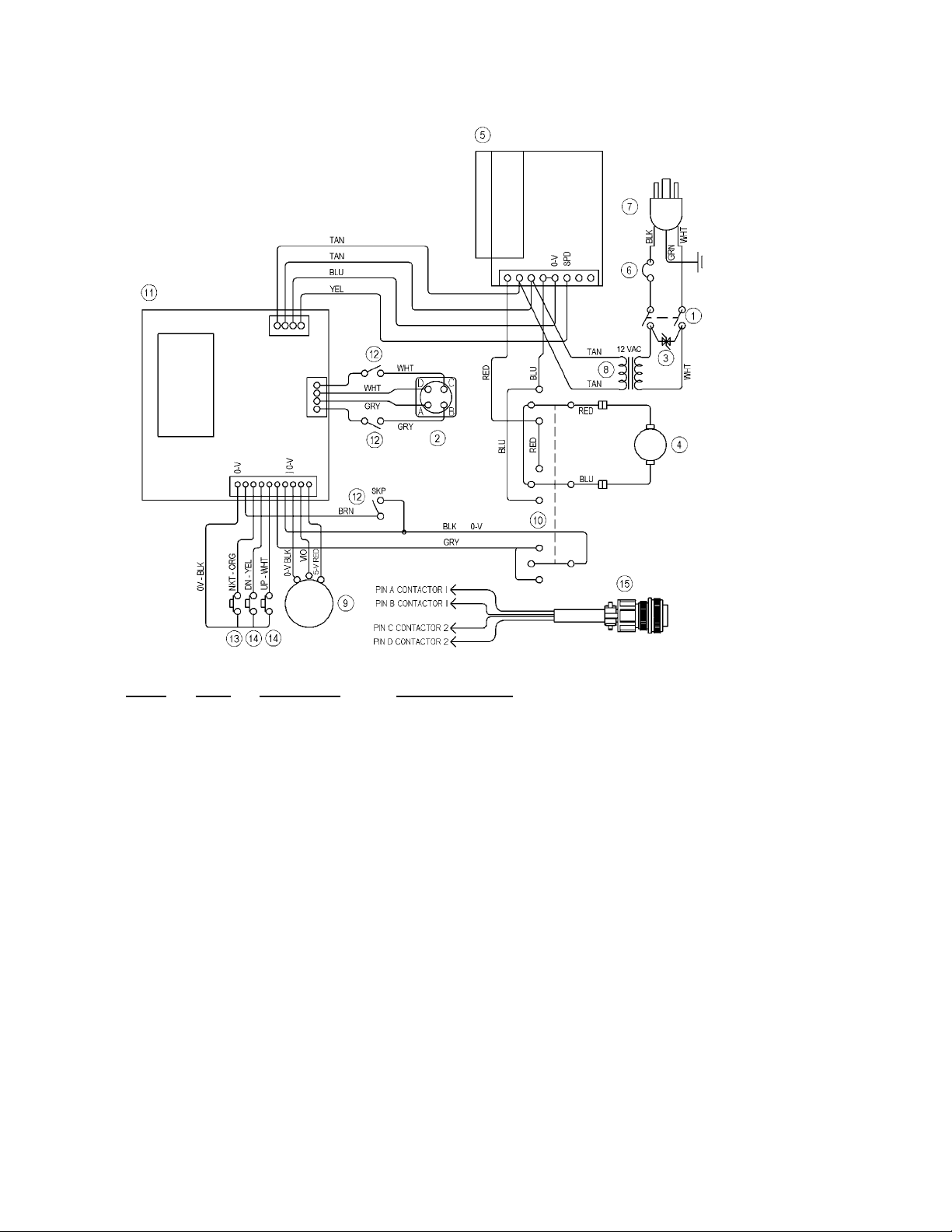
UNI-BUG III WIRING DIAGRAM / PARTS LIST
14
ITEM QTY PART NO. DESCRIPTION
1 1 ARM-2279 Toggle Switch
2 1 BUG-1034 Panel Connector
3* 1 BUG-1393 Volt Trap 120 VAC
3** 1 BUG-1563 Volt Trap 240 VAC
3*** 1 BUG-1393 Volt Trap 120 VAC
4 1 BUG-1550 Gear Motor 150:1
5 1 BUG-1735 Speed Control
6* 1 BUG-2923 .7 Amp Circuit Breaker
6** 1 BUG-2952 .5 Amp Circuit Breaker
6*** 1 BUG-2933 2 Amp Circuit Breaker
7* 1 BUG-9445 Power Cord
7** 1 GOF-3115 Power Cord
7*** 1 BUG-9442 Power Cord
8* 1 BUG-9675 Transformer
8** 1 GOF-3112 Transformer
8*** 1 BUG-1466 Transformer
9 1 BUG-9677 Potentiometer
10 1 MUG-1258 Rotary Switch
11 1 PCB-2400 Stitch Board
12 3 SWT-7101 Toggle Switch
13 1 SWT-1111 NOR. Open Push Button
14 2 SWT-3502 NOR. Open Push Button
15 1 BUG-1035 Cable Connector
* 120 VAC Part Number
** 240 VAC Part Number
*** 42 VAC Part Number
Page 15

UNI-BUG III SINGLE GUN WELDING KIT
UNI-2500, 2502, 2504
The UNI-2500 UNI-BUG III Single Gun Kit is equipped for the
mounting of a single gun and provides components to manually
adjust the gun in the vertical and horizontal plane. The UNI-BUG
III provides programmable control for stitch or continuous welding
and is designed to mount and run on the top edge of a at bar or
stiffener with a minimum height of 2" (51 mm) and a maximum
width of 2" (51 mm). The machine will turn on a radius down to 6"
(160 mm). The unit will travel at speeds from 4 to 75 inches per
minute (102 - 1905 mm/min) and has a horizontal load capacity
of 50 lbs. (22.7 kg).
1
Included
with
2
Item #2
ITEM QTY PART NO. DESCRIPTION
1 1 UNI-2400 UNI-BUG III 120 VAC
1 1 UNI-2402 UNI-BUG III 240 VAC
1 1 UNI-2404 UNI-BUG III 42 VAC
2 1 BUG-1855 UNI-BUG Welding Group
15
Page 16

UNI-BUG III DUAL GUN WELDING KIT
UNI-2600, 2602, 2604
The UNI-2600 UNI-BUG III Dual Gun Welding Kit is equipped
for the mounting of two welding guns and provides components
to independently adjust either gun in the vertical and horizontal
plane. The unit features programmable control for stitch or
continuous welding and is designed to mount and run on the top
edge of a at bar or stiffener with a minimum height of 2" (51 mm)
and a maximum width of 2" (51 mm). The machine will turn on a
radius down to 6" (152 mm). The unit will travel at speeds from 4
to 75 inches per minute (102-1905 mm/min) and has a horizontal
load capacity of 50 lbs. (22.7 kg).
3
16
1
2
ITEM QTY PART NO. DESCRIPTION
1 1 UNI-2400 UNI-BUG III 120 VAC
1 1 UNI-2402 UNI-BUG III 240 VAC
1 1 UNI-2404 UNI-BUG III 42 VAC
2 1 UNI-1350 UNI-BUG Dual Welding Group
3 1 UNI-1355 Dual Cable Anchor
Page 17

UNI-BUG III BULB DUAL GUN WELDING KIT
UNI-2700, 2702, 2704
The UNI-2700 UNI-BUG III Dual Gun Bulb Prole Welding Kit
is equipped for the mounting of two welding guns and provides
components to independently adjust either gun in the vertical and
horizontal plane. The unit features programmable control for stitch
or continuous welding and is designed for straight line welding
of Bulb Proles. This unit will mount and run on Bulb sizes from
5.5" to 17" (140 mm to 430 mm). The unit will travel at speeds
from 4 to 75 inches per minute (102-1905 mm/min) and has a
horizontal load capacity of 50 lbs. (22.7 kg).
3
1
2
ITEM QTY PART NO. DESCRIPTION
1 1 UNI-2720 UNI-BUG III Bulb120 VAC
1 1 UNI-2722 UNI-BUG III Bulb 240 VAC
1 1 UNI-2724 UNI-BUG III Bulb 42 VAC
2 1 UNI-1350 UNI-BUG Dual Welding Group
3 1 UNI-1355 Dual Cable Anchor
17
Page 18

UNI-BUG III “T” DUAL GUN WELDING KIT
UNI-2800-4, 2802-4, 2804-4
The UNI-2800-4 UNI-BUG III Dual Gun “T” Prole Welding Kit
is equipped for the mounting of two welding guns and provides
components to independently adjust either gun in the vertical
and horizontal plane. The unit features programmable control
for stitch or continuous welding and is designed for straight line
welding of “T” Proles. This unit will mount and run on top of “T”
Proles with a minimum height of 2" (51 mm) and widths from
2"-4" (51-102 mm). The unit will travel at speeds from 4 to 75
inches per minute (102-1905 mm/min) and has a horizontal load
capacity of 50 lbs. (22.7 kg).
3
18
1
2
ITEM QTY PART NO. DESCRIPTION
1 1 UNI-2840 UNI-BUG III 2''-4'' “T” 120 VAC
1 1 UNI-2842 UNI-BUG III 2''-4'' “T” 220 VAC
1 1 UNI-2844 UNI-BUG III 2''-4'' “T” 42 VAC
2 1 UNI-1350 UNI-BUG Dual Welding Group
3 1 UNI-1355 Dual Cable Anchor
Page 19

UNI-BUG III “T” DUAL GUN WELDING KIT
UNI-2800-6, 2802-6, 2804-6
The UNI-2800-6 UNI-BUG III Dual Gun “T” Prole Welding Kit
is equipped for the mounting of two welding guns and provides
components to independently adjust either gun in the vertical
and horizontal plane. The unit features programmable control
for stitch or continuous welding and is designed for straight line
welding of “T” Proles. This unit will mount and run on top of “T”
Proles with a minimum height of 2" (51 mm) and widths from
4"-6'' (102-152 mm). The unit will travel at speeds from 4 to 75
inches per minute (102-1905 mm/min) and has a horizontal load
capacity of 50 lbs. (22.7 kg).
3
1
2
ITEM QTY PART NO. DESCRIPTION
1 1 UNI-2820 UNI-BUG III “T” 120 VAC
1 1 UNI-2822 UNI-BUG III “T” 240 VAC
1 1 UNI-2824 UNI-BUG III “T” 42 VAC
2 1 UNI-1350 UNI-BUG Dual Welding Group
3 1 UNI-1355 Dual Cable Anchor
19
Page 20

UNI-BUG III “L” DUAL GUN WELDING KIT
UNI-2900, 2902, 2904
The UNI-2900 UNI-BUG III Dual Gun “L” Prole Welding Kit is
equipped for the mounting of two welding guns and provides
components to independently adjust either gun in the vertical and
horizontal plane. The unit features programmable control for stitch
or continuous welding and is designed for straight line welding
of “L” Proles. The unit will mount and run on top of inverted “L”
Proles or angle with a minimum height of 4" (102 mm) and widths
up to 4" (102 mm). The unit will travel at speeds from 4 to 75
inches per minute (102 - 1905 mm/min) and has a horizontal load
capacity of 50 lbs. (22.7 kg).
3
20
1
2
ITEM QTY PART NO. DESCRIPTION
1 1 UNI-2920 UNI-BUG III “L” 120 VAC
1 1 UNI-2922 UNI-BUG III “L” 240 VAC
1 1 UNI-2924 UNI-BUG III “L” 42 VAC
2 1 UNI-1350 UNI-BUG Dual Welding Group
3 1 UNI-1355 Dual Cable Anchor
Page 21

UNI-2400 UNI-BUG III / EXPLODED VIEW / PARTS LIST
6
1
4
5
2
8
8
9
7
9
ITEM QTY PART NO. DESCRIPTION
1 1 BUG-1338 Name Plate
2 1 BUG-1785 Handle
3 1 BUG-9444 Tool Kit
4 1 UNI-2410 Cover Assembly 120 VAC
4 1 UNI-2412 Cover Assembly 240 VAC
4 1 UNI-2414 Cover Assembly 42 VAC
5 1 UNI-2417 Left Side Panel
6 1 UNI-2418 Right Side Panel
7 1 UNI-1020 Base Assembly
8 8 FAS-1214 But. Hd. Sk Scr 6-32 x 3/8"
9 4 FAS-1223 But. Hd. Sk Scr 8-32 x 5/16"
3
21
Page 22

UNI-2410 COVER ASSEMBLY / EXPLODED VIEW
15,5
11,16,19,32
24
8,12,21
29
28
33
30
27
22,13
27
9,26,32
31,18,17,2
23,14
25
1,4
6,7
9,10,20
3
NOTE: SeeUNI-BUGIIIwiringdiagramforvoltagespecicelectricalcomponents.
22
Page 23

UNI-2410 COVER ASSEMBLY / PARTS LIST
ITEM QTY PART NO. DESCRIPTION
1 1 ARM-2279 Toggle Switch
2 1 BUG-1034 Panel Connector
3 1 BUG-1035 Cable Connector
4 1 BUG-1393 Volt Trap 120 VAC
5 1 BUG-1735 Speed Control
6 1 BUG-2923 .7 AMP Circuit Breaker
7 1 BUG-2924 Reset Seal
8 1 BUG-5759 Pot Shaft Seal
9 1 BUG-9445 Power Cord
10 1 BUG-9446 Cord Grip
11 1 BUG-9675 Transformer
12 1 BUG-9677 Potentiometer
13 1 BUG-9694 Knob
14 4 FAS-0104 Pan Hd Scr 4-40 x 3/8"
15 2 FAS-0112 Pan Hd Slt Scr 6-32 x 1/4"
16 2 FAS-0124 Pan Hd Scr 8-32 x 3/8"
17 4 FAS-0205 Rnd Hd Scr 4-40 x 1/2"
18 4 FAS-1305 Hex Nut 4-40
19 3 FAS-1320 Hex Nut 8-32
20 1 FAS-3150 Nut, Cord Grip
21 1 MDS-1044 Knob - Yellow
22 1 MUG-1258 Rotary Switch
23 1 PCB-2400 Stitch Board
24 1 PLT-2400-A Face Plate #1
25 1 PLT-2400-B Face Plate #2
26 1 SCW WTE 0514 Pan Hd Scr 8-32 x 3/8"
27 3 SWT-7101 Toggle Switch
28 1 SWT-1111 Nor. Open Push Button
29 2 SWT-3502 Nor. Open Push Button
30 1 UNI-2416 Cover Panel
31 4 WAS-0201 #4 INT Star Lock Washer
32 3 WAS-0221 #8 INT Star Lock Washer
33 1 PLT-2401 UNI-BUG-III Display Filter
NOTE: SeeUNI-BUGIIIwiringdiagramforvoltagespecicelectricalcomponents.
23
Page 24

UNI-2720 UNI-BUG III BULB / EXPLODED VIEW / PARTS LIST
4
1
4
5
8
9
6
8
24
7
9
ITEM QTY PART NO. DESCRIPTION
1 1 BUG-1338 Name Plate
2 1 BUG-1785 Handle
3 1 BUG-9444 Tool Kit
4 1 UNI-2410 Cover Assembly 120 VAC
4 1 UNI-2412 Cover Assembly 240 VAC
4 1 UNI-2414 Cover Assembly 42 VAC
5 1 UNI-2417 Left Side Panel
6 1 UNI-2418 Right Side Panel
7 1 UNI-2220 Bulb Base Assembly
8 8 FAS-1214 But. Hd. Sk Scr 6-32 x 3/8"
9 4 FAS-1223 But. Hd. Sk Scr 8-32 x 5/16"
3
Page 25

UNI-2820 UNI-BUG III “T” / EXPLODED VIEW / PARTS LIST
2
1
4
5
8
9
6
8
9
7
ITEM QTY PART NO. DESCRIPTION
1 1 BUG-1338 Name Plate
2 1 BUG-1785 Handle
3 1 BUG-9444 Tool Kit
4 1 UNI-2410 Cover Assembly 120 VAC
4 1 UNI-2412 Cover Assembly 240 VAC
4 1 UNI-2414 Cover Assembly 42 VAC
5 1 UNI-2417 Left Side Panel
6 1 UNI-2418 Right Side Panel
7 1 UNI-2120 “T” Base Assembly
8 8 FAS-1214 But. Hd. Sk Scr 6-32 x 3/8"
9 4 FAS-1223 But. Hd. Sk Scr 8-32 x 5/16"
3
25
Page 26

UNI-2840 UNI-BUG III “T” / EXPLODED VIEW / PARTS LIST
6
1
4
5
2
8
8
9
9
7
ITEM QTY PART NO. DESCRIPTION
1 1 BUG-1338 Name Plate
2 1 BUG-1785 Handle
3 1 BUG-9444 Tool Kit
4 1 UNI-2410 Cover Assembly 120 VAC
4 1 UNI-2412 Cover Assembly 240 VAC
4 1 UNI-2414 Cover Assembly 42 VAC
5 1 UNI-2417 Left Side Panel
6 1 UNI-2418 Right Side Panel
7 1 UNI-2140 2"-4" “T” Stiffener Base Assembly
8 8 FAS-1214 But. Hd. Sk Scr 6-32 x 3/8"
9 4 FAS-1223 But. Hd. Sk Scr 8-32 x 5/16"
3
26
Page 27

UNI-2920 UNI-BUG “L” / EXPLODED VIEW / PARTS LIST
6
1
4
5
2
8
8
9
3
7
9
ITEM QTY PART NO. DESCRIPTION
1 1 BUG-1338 Name Plate
2 1 BUG-1785 Handle
3 1 BUG-9444 Tool Kit
4 1 UNI-2410 Cover Assembly 120 VAC
4 1 UNI-2412 Cover Assembly 240 VAC
4 1 UNI-2414 Cover Assembly 42 VAC
5 1 UNI-2417 Left Side Panel
6 1 UNI-2418 Right Side Panel
7 1 UNI-2020 “L” Base Assy.
8 8 FAS-1214 But. Hd. Sk Scr 6-32 x 3/8"
9 4 FAS-1223 But. Hd. Sk Scr 8-32 x 5/16"
27
Page 28

UNI-1020 BASE ASSEMBLY / EXPLODED VIEW
3
16
25
24
2
18
30
22
20
19
32
33
29
14
12
17
10
17
33
31
15
6
15
12
17
10
17
26
13
21
27
7
1
23
13
8
11
9
28
4
5
28
Page 29

UNI-1020 BASE ASSEMBLY / PARTS LIST
ITEM QTY PART NO. DESCRIPTION
1 2 BER-1001 Flg. Brg. .502 x .627 x .750 x .094
2 2 BER-1002 Thrust Washer .627 x 1.004 x .063
3 1 BUG-1550 Gear Motor 150:1
4 1 BUG-1854 Screw Block w/ Insert
5 2 BUG-1858 Soc Hd Shr Bolt 5/16 x 1-1/4 x 1/4-20
6 2 BUG-1859 Bearing Spacer
7 1 BUG-1863-R Idler Channel
8 2 BUG-1888 Drive Roll
9 2 BUG-1893 Retaining Ring 1/2" External
10 2 BUG-1895 Roller Bearing Assembly
11 2 BUG-1897 Sleeve
12 2 BUG-1898 Axle
13 4 BUG-1899 Washer 1-1/6" O.D. x 1/2" I.D. x 1/32"
14 2 BUG-1988 Belleville Washer
15 4 BUG-2012 Bearing
16 4 BUG-5121 Stand Off
17 4 CON-1029 Washer 5/16" x .015"
18 2 FAS-0357 Hex Hd Cap Scr 1/4-20 x 3/4
19 4 FAS-0525 Soc Hd Cap Scr 8-32 x 1/2"
20 1 FAS-1445 Phil Pan Hd Scr 10-32 x 1/2"
21 4 FAS-2824 Flt Hd Slt Scr 8-32 x 1-3/4"
22 1 UNI-1021 Base Plate
23 2 UNI-1022 Slave Shaft
24 2 UNI-1024 Slave Pinion
25 1 UNI-1025 Pinion / Sleeve Assembly
26 2 UNI-1029 Shaft Spacer
27 1 UNI-1030 Tensioning Screw Assembly
28 1 UNI-1040 Drive Wheel Blk. Assembly
29 1 WAS-0230 #10 Washer
30 2 WAS-0240 1/4" SAE Washer
31 1 UNI-1332 Rail Guide
32 1 PWS-1037 Slider Guide Rail
33 9 MET-0522-SS Soc Hd Cap Scr M2 x 8
29
Page 30

UNI-2020 “L” BASE ASSEMBLY / EXPLODED VIEW
3
15
11
17
28
21
23
2
30
13
9
16
6
31
32
11
20
22
29
17
4
19
9
16
1
26
12
10
24
7
25
8
18
5
30
14
27
Page 31

UNI-2020 “L” BASE ASSEMBLY / PARTS LIST
ITEM QTY PART NO. DESCRIPTION
1 2 BER-1001 Flg Brg .502 x .627 x .375 x .750 x .094
2 2 BER-1002 Thrust Washer .627 x 1.004 x .063
3 1 BUG-1550 Gear Motor (150:1)
4 2 BUG-1858 Soc Hd Shr Scr 5/16 x 1-1/4 x 1/4-20
5 2 BUG-1859 Bearing Spacer
6 1 BUG-1863-R Idler Channel
7 2 BUG-1888 Drive Roll
8 2 BUG-1893 Retaining Ring 1/2" External
9 2 BUG-1895 Roller Bearing Assembly
10 2 BUG-1897 Sleeve
11 2 BUG-1898 Axle
12 4 BUG-1899 Washer 1-1/6" O.D. x 1/2" I.D. x 1/32"
13 2 BUG-1988 Belleville Washer .323 I.D. x .709 O.D.
14 4 BUG-2012 Bearing
15 4 BUG-5121 Stand Off
16 4 CON-1029 Washer 5/16" x .015"
17 4 FAS-0525 Soc Hd Cap Scr 8-32 x 1/2"
18 2 FAS-2559 Soc Hd Cap Scr 1/4-20 x 3"
19 1 FAS-1445 Phil Pan Hd Scr 10-32 x 1/2"
20 4 FAS-2824 Flt Hd Slt Scr 8-32 x 1-3/4"
21 1 UNI-1021 Base Plate
22 2 UNI-1024 Slave Pinion
23 1 UNI-1025 Pinion / Sleeve Assembly
24 1 UNI-1034 Uni-Bug Drive Wheel Spacer
25 1 UNI-1040 Drive Wheel Blk Assembly
26 2 UNI-1062 Shaft Spacer 1-3/8" LG.
27 2 UNI-1063 Slave Shaft 4" LG.
28 1 UNI-1320 Angle Adaptor Kit
29 1 WAS-0230 #10 Washer
30 2 WAS-0240 1/4" SAE Washer
31 1 UNI-1332 Rail Guide
32 4 MET-0552-SS Soc Hd Scr M2 x 8
31
Page 32

UNI-2120 “T” BASE ASSEMBLY / EXPLODED VIEW
3
7
17
17
6
13
12
2
10
17
6
18
5
8
9
18
8
5
8
1
14
19
4
11
32
15
16
20
Page 33

UNI-2120 “T” BASE ASSEMBLY / PARTS LIST
ITEM QTY PART NO. DESCRIPTION
1 2 BER-1001 Flg Brg .502 x .627 x .375 x .750 x .094
2 2 BER-1002 Thrust Washer .627 x 1.004 x .063
3 1 BUG-1550 Gear Motor (150:1)
4 2 BUG-1893 Retaining Ring 1/2" External
5 2 BUG-1895 Roller Bearing Assembly
6 2 BUG-1898 Axle
7 4 BUG-5121 Stand Off
8 4 CON-1029 Washer
9 4 FAS-2824 Flt Hd Slt Scr 8-32 x 1-3/4"
10 1 UNI-1021 Base Plt.
11 2 UNI-1022 Slave Shaft
12 2 UNI-1024 Slave Pinion
13 1 UNI-1025 Pinion / Sleeve Assembly
14 2 UNI-1029 Shaft Spacer
15 1 UNI-1040 Drive Wheel Blk. Assembly
16 1 UNI-1336 Adaptor 6" T Stiffener Kit
17* 4 BUG-1528 Spacer
18* 4 FAS-0527 Soc Hd Scr 8-32 x 3/4"
19* 2 UNI-1019 Steel Drive Roll
20* 1 UNI-2130 Tension Wheel Assembly
NOTE: (*) Included in UNI-1336 Adaptor T-Stiffener Kit.
33
Page 34

UNI-2140 “T” BASE ASSEMBLY / EXPLODED VIEW
3
7
17
17
6
13
12
2
10
17
6
18
5
8
9
18
8
5
8
1
14
19
4
11
34
15
16
20
Page 35

UNI-2140 “T” BASE ASSEMBLY / PARTS LIST
ITEM QTY PART NO. DESCRIPTION
1 2 BER-1001 Flg Brg .502 x .627 x .375 x .750 x .094
2 2 BER-1002 Thrust Washer .627 x 1.004 x .063
3 1 BUG-1550 Gear Motor (150:1)
4 2 BUG-1893 Retaining Ring 1/2" External
5 2 BUG-1895 Roller Bearing Assembly
6 2 BUG-1898 Axle
7 4 BUG-5121 Stand Off
8 4 CON-1029 Washer
9 4 FAS-2824 Flt Hd Slt Scr 8-32 x 1-3/4"
10 1 UNI-1021 Base Plt.
11 2 UNI-1022 Slave Shaft
12 2 UNI-1024 Slave Pinion
13 1 UNI-1025 Pinion / Sleeve Assembly
14 2 UNI-1029 Shaft Spacer
15 1 UNI-1040 Drive Wheel Blk. Assembly
16 1 UNI-1330 Adaptor 2"-4'' T Stiffener Kit
17* 4 BUG-1528 Spacer
18* 4 FAS-0527 Soc Hd Scr 8-32 x 3/4"
19* 2 UNI-1019 Steel Drive Roll
20* 1 UNI-2130 Tension Wheel Assembly
NOTE: (*) Included in UNI-1330 Adaptor T-Stiffener Kit.
35
Page 36

UNI-2220 BULB BASE ASSEMBLY / EXPLODED VIEW
20
29
3
16
28
27
6
15
7
14
4
5
25
24
2
22
18
18
12
17
10
17
1
26
13
11
36
12
18
18
10
8
21
13
9
17
23
19
17
Page 37

UNI-2220 BULB BASE ASSEMBLY / PARTS LIST
ITEM QTY PART NO. DESCRIPTION
1 2 BER-1001 Flg Brg .502 x .627 x .375 x .750 x .094
2 2 BER-1002 Thrust Washer .627 x 1.004 x .063
3 1 BUG-1550 Gear Motor (150:1)
4 1 BUG-1854 Screw Block w/ Insert
5 2 BUG-1858 Soc Hd Shr Scr 5/16 x 1-1/4 x 1/4-20
6 2 BUG-1859 Bearing Spacer
7 1 BUG-1863 Idler Channel
8 2 BUG-1888 Drive Roll
9 2 BUG-1893 Retaining Ring 1/2" External
10 2 BUG-1895 Roller Bearing Assembly
11 2 BUG-1897 Sleeve
12 2 BUG-1898 Axle
13 4 BUG-1899 Washer 1-1/6" O.D. x 1/2" I.D. x 1/32"
14 2 BUG-1988 Belleville Washer .323 I.D. x .709 O.D.
15 4 BUG-2012 Bearing
16 4 BUG-5121 Stand Off
17 4 CON-1029 Washer 5/16" x .015"
18 4 FAS-0525 Soc Hd Cap Scr 8-32 x 1/2"
19 1 UNI-1040 Drive Wheel Blk. Assembly
20 1 FAS-1445 Phil Pan Hd Scr 10-32 x 1/2"
21 4 FAS-2824 Flt Hd Slt Scr 8-32 x 1-3/4"
22 1 UNI-1021 Base Plate
23 2 UNI-1022 Slave Shaft
24 2 UNI-1024 Slave Pinion
25 1 UNI-1025 Pinion / Sleeve Assembly
26 2 UNI-1029 Shaft Spacer
27 1 UNI-1030 Tensioning Screw Assembly
28 1 UNI-1305 Bulb Flat Welder Adaptor
29 1 WAS-0230 #10 Washer
37
Page 38

UNI-1350 DUAL WELDING GROUP / EXPLODED VIEW / PARTS LIST
7
7
4
1
5
8
2
1
1
4
5
8
1
3
6
3
38
6
ITEM QTY PART NO. DESCRIPTION
1 4 BUG-1796 Machined Rack 14"
2 1 BUG-1891 Double Racker Mount
3 2 BUG-2708 Clamp
4 2 BUG-5451 3.5" Rackholder
5 2 BUG-5462 Right Angle Clamp
6 2 CON-1020 Swivel Clamp Assembly
7 2 FAS-0957 Flt Hd Scr 1/4-20 x 3/4"
8 2 UNI-1036 Rackholder w/ Post
Page 39

UNI-1355 DUAL CABLE ANCHOR / EXPLODED VIEW / PARTS LIST
2
4
3
1
4
2
ITEM QTY PART NO. DESCRIPTION
1 2 BUG-2660 Fits All Clamp
2 1 BUG-5462 Right Angle Clamp
3 1 BUG-9180-18 Rod 18"
4 2 PAN-1033 Rod Clamp
39
Page 40

BUG-1855 WELDING GROUP / EXPLODED VIEW / PARTS LIST
4
2
1
5
8
7
40
3
1
6
ITEM QTY PART NO. DESCRIPTION
1 2 BUG-1853 Machined Rack 7-1/2"
2 1 BUG-1881 Cable Anchor w/ Swivel
3 1 BUG-2708 Clamp
4 1 BUG-5451 3.5" Rack Holder
5 1 BUG-5462 Right Angle Clamp
6 1 CON-1020 Swivel Clamp Assembly
7 2 FAS-0957 Flt Hd Soc Scr 1/4-20 x 3/4"
8 1 UNI-1036 Rackrider w/ Post
Page 41

BUG-1875 CUTTING GROUP / EXPLODED VIEW / PARTS LIST
6
8
8
3
9
5
7
1
2
4
7
ITEM QTY PART NO. DESCRIPTION
1 1 BUG-1853 Machined Rack 7-1/2"
2 1 BUG-5188 Torch Holder Assembly
3 1 BUG-5451 3.5" Rackholder
4 1 BUG-5462 Right Angle Clamp
5 1 BUG-9729 Spacer
6 1 CIR-1010-2 Hose Assembly
7 2 FAS-0957 Flt Hd Soc Scr 1/4-20 x 3/4"
8 2 FAS-2353 Hex Hd Cap Scr 1/4-20 x 1/2"
9 1 GOF-3025 Quick-Acting Manifold
41
Page 42

TROUBLESHOOTING GUIDE
PROBLEM CAUSE REMEDY
Does not run. No input power • Turn on the circuit breaker
Indicator lights off. • Plug in the line cord
• Insure there is power at the outlet
Broken wire • Unplug the machine from power. Examine internally
and rewire at fault.
Bad circuit • Replace if breaker has input power and no output
when in the “ON” position
Bad travel switch • Replace if breaker has input power and no output
when “ON”
Does not run. Indicator Wiring short • Unplug the machine from power. Examine internally
light off and circuit and rewire at fault.
breaker is tripped.
Burned out part • Unplug the machine from power. Examine internally
and replace any part that looks burned up.
Other • Can only be determined by factory or qualied repair
person.
Does not run. Indicator Bad connection • Unplug the machine from power. Examine internally
light on. and x any broken connections.
• Tighten terminal screws on speed control board.
Open transformer • Replace the transformer if there is input power on
the primary and no output on the secondary.
(12 VAC/CT is expected.)
Burned out part • Unplug the machine from power. Examine internally
and replace any part that looks burned up.
Wiring short • Unplug the machine from power. Examine internally
and rewire fault.
Failed motor • Replace the motor if it has input voltage and does
not run.
Failed control card • Unplug the machine from power. Check the card
for damaged traces or parts. Repair or replace if
required.
• Verify the card has 12 VAC/CT input power.
Replace the card if the output to the motor leads is
0 volts with the speed knob at maximum.
Other • Can only be determined by factory or qualied
repair person.
42
Page 43

TROUBLESHOOTING GUIDE, CONT’D.
PROBLEM CAUSE REMEDY
Unit runs, but no Faulty control card • Unplug the machine from power. Verify there are
speed control. no bad connections to the control card or on the
board. Replace the card.
Failed speed • Replace if visually appears damaged. Verify no
potentiometer loose or broken connections to the part.
Unit runs, but erratic Poor input voltage • Verify the machine power source is stable and at
or poor speed control. regulation the correct voltage. Measure at the outlet.
Faulty control card • Unplug the machine from power. Verify there are no
bad connections to the control card or board.
Replace the board.
Damaged wheel or • Turn the machine upside down and off. Replace
wheel assembly any wheels that are damaged. Replace any idler
wheels that do not freely turn.
Pitted workpiece • Verify the workpiece is not pitted or damaged in a
way that will give an uneven drive surface to the
machine wheels. Verify the workpiece thickness
does not vary signicantly where the machine
wheels travel.
43
Page 44

WARRANTY
Model ____________________________
Limited 3-Year Warranty
For a period ending one (1) year from the date of invoice, Manufacturer warrants that any new machine or part is free from defects in materials and workmanship and Manufacturer agrees to repair or
replace at its option, any defective part or machine. HOWEVER, if the invoiced customer registers
the Product Warranty by returning the Warranty Registration Card supplied with the product within
90 days of the invoice date, or by registering on-line at www.bugo.com, Manufacturer will extend the
warranty period an additional two (2) years which will provide three (3) total years from the date of
original invoice to customer. This warranty does not apply to machines which, after Manufacture’s
inspection are determined by Manufacturer to have been damaged due to neglect, abuse, overloading, accident or improper usage. All shipping and handling charges will be paid by the customer.
The foregoing express warranty is exclusive and Manufacturer makes no representation or warranty
(either express or implied) other than as set forth expressly in the preceding sentence. Specifically,
Manufacturer makes no express or implied warranty of merchantability or fitness for any particular
purpose with respect to any goods. Manufacturer shall not be subject to any other obligations or liabilities whatsoever with respect to machines or parts furnished by Manufacturer.
Manufacturer shall not in any event be liable to Distributor or any customer for any loss of profits, incidental or consequential damages or special damages of any kind. Distributor’s or customer’s sole
and exclusive remedy against Manufacturer for any breach of warranty, negligence, strict liability or
any other claim relating to goods delivered pursuant hereto shall be for repair or replacement (at
Manufacturer’s option) of the machines or parts affected by such breach.
Serial No. _________________________
Date Purchased: ___________________
Where Purchased: _________________
Distributor’s Warranty:
In no event shall Manufacturer be liable to Distributor or to any customer thereof for any warranties,
representations or promises, express or implied, extended by Distributor without the advance written consent of Manufacturer, including but not limited to any and all warranties of merchantability or
fitness for a particular purpose and all warranties, representations or promises which exceed or are
different from the express limited warranty set forth above. Distributor agrees to indemnify and hold
Manufacturer harmless from any claim by a customer based upon any express or implied warranty
by Distributor which exceeds or differs from Manufacturer’s express limited warranty set forth above.
HOW TO OBTAIN SERVICE:
If you think this machine is not operating properly, re-read the instruction manual carefully,
then call your Authorized BUG-O dealer/distributor. If they cannot give you the necessary
service, write or phone us to tell us exactly what difculty you have experienced. BE SURE to
mention the MODEL and SERIAL numbers.
44
 Loading...