

Page 1

INSTRUCTIONS
AND
PARTS MANUAL
TRAC-BUG
Please record your equipment identication information below for future reference.
This information can be found on your machine nameplate.
Model Number:_________________________________________
Serial Number:_________________________________________
Date of Purchase:_______________________________________
Whenever you request replacement parts or information on this equipment, always
supply the information you have recorded above.
LIT-TRB-IPM-1014
Bug-O Systems is guided by honesty, integrity and
ethics in service to our customers and in all we do.
A DIVISION OF WELD TOOLING CORPORATION
280 TECHNOLOGY DRIVE CANONSBURG, PENNSYLVANIA, 15317-9564 USA
PHONE: 412-331-1776 http://www.bugo.com FAX: 412-331-0383
Page 2
SAFETY
PROTECT YOURSELF AND OTHERS FROM SERIOUS INJURY OR
DEATH. KEEP CHILDREN AWAY. BE SURE THAT ALL INSTALLATION,
OPERATION, MAINTENANCE AND REPAIR PROCEDURES ARE
PERFORMED ONLY BY QUALIFIED INDIVIDUALS.
ELECTRIC SHOCK can kill.
1. The equipment is not waterproof. Using the
unit in a wet environment may result in
serious injury. Do not touch the equipment
when wet or standing in a wet location.
2.Never open the equipment without rst
unplugging the power cord or serious
injury may result.
3.Verify the customer-supplied power
connections are made in accordance
with all applicable local and national
electrical safety codes. If none exist,
use International Electric Code (IEC) 950.
4.Never remove or bypass the equipment
power cord ground. Verify the equipment
is grounded in accordance with all
applicable local and national electrical
safety codes. If none exist, use
International Electrical Code (IEC) 950.
READ INSTRUCTIONS.
Read the instruction manual before
installing and using the equipment.
EQUIPMENT DAMAGE
POSSIBLE.
1. Do not plug in the power cord without
rst verifying the equipment is OFF and
the cord input voltage is the same as
required by the machine or serious
damage may result.
2. Do not leave the equipment unattended.
Remove from the work site and store in
a safe location when not in use.
FALLING EQUIPMENT
can cause serious
personal injury and
equipment damage.
Faulty or careless user installation is
possible. As a result, never stand or
walk underneath equipment.
MOVING PARTS can
cause serious injury.
1.Never try to stop the pinion from moving
except by removing power or by using
the STOP control.
2. Do not remove any protective panels,
covers or guards and operate equipment.
CAUTION
DO NOT LEAVE EQUIPMENT UNATTENDED
WHEN NOT IN USE!
Remove from work site and store in a safe location.
3
Page 3

TRAC-BUG
INSTRUCTION AND PARTS MANUAL
TABLE OF CONTENTS
PAGE
5.......... Operating Instructions / Set-Up
6.......... Trac-Bug / Oxy-fuel / Technical Data
7.......... Trac-Bug / Oxy-fuel / Exploded View / Parts List
8.......... Trac-Bug / Plasma / Technical Data
9.......... Trac-Bug / Plasma / Exploded View / Parts List
10........ TRB-1010 Base Assembly / Exploded View / Parts List
11 ........ TRB-1020 Cover Assembly / Exploded View / Parts List
12........ TRB-1030 Rear Plate Assembly / Exploded View / Parts List
13........ TRB-1040 Clutch Assembly / Exploded View / Parts List
14........ TRB-1050 Drive Section / Exploded View / Parts List
15........ Trac-Bug Wiring Diagram / Electrical Component Chart
16........ Trac-Bug Track
17........ TRB-1160 Radius Kit Installation / Exploded View / Parts List
18........ TRB-1153 Radius Riser Assembly / Exploded View / Parts List
19........ TRB-1155 Radius Arm Attachment / Exploded View / Parts List
20........ Troubleshooting Guide
21........ Warranty
THIS PRODUCT IS COVERED BY ONE OR
MORE PATENTS WORLD WIDE.
4
Page 4

OPERATING INSTRUCTIONS / SET-UP
1. TRACK SET-UP
The TRAC-BUG will run on any 6" centerline, “V” groove friction track.
To position track, simply set it parallel to the cut line of the work piece.
For most applications, such as straight or bevel cutting, the rail should be
set within 6" to 10" of the cut line. Snapping a chalk line will aid in
set-up. Rails can be joined for long cuts.
2. TORCH SET-UP
Insert the torch into the torch holder on the rack. Adjust the torch holder,
the clamp and the rack to set the torch to the desired position. Connect
the Twin Hose Assembly to the Quick Action Manifold and to the
cutting torch. The manifold provides strain relief for the supply hoses
and quick shut off of the gas supply to the torch. Once the torch is
adjusted, the manifold eliminates the need to readjust the valves after
each cut and prevents the supply hoses from dragging the torch out
of position.
3. MACHINE SET-UP
The TRAC-BUG can be positioned anywhere along the track and in
either direction. Be sure the wheels are seated into the “V” of the track.
Disengage the clutch on the rear of the unit to allow free rolling along
track. Rack torch support to position torch over cut line and roll the unit
back and forth to conrm alignment with the cut line. Reengage clutch.
4. MACHINE OPERATION
Set Toggle Switch to the center “STOP” position. Connect power cord
to the appropriate voltage supply. Throw Toggle Switch to either
direction to verify power to the unit. Adjust travel speed using the Speed
Control. The Circuit Breaker protects the unit from overload or
electrical faults.
CAUTION: IF CIRCUIT BREAKER OPENS, FIND AND CORRECT THE
PROBLEM BEFORE RESETTING.
5
Page 5
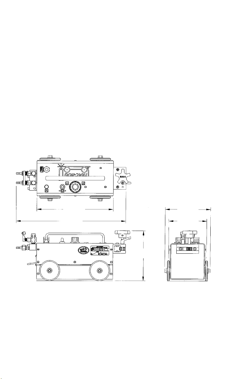
TRAC-BUG / OXY-FUEL
TECHNICAL DATA
Power requirement: 60 watts at rated voltage.
TRB-1000 TRAC-BUG for Oxy-fuel 120 VAC/50-60/1
TRB-1002 TRAC-BUG for Oxy-fuel 240 VAC/50-60/1
TRB-1004 TRAC-BUG for Oxy-fuel 42 VAC/50-60/1
Travel Speed: Innitely variable from 4-72 ipm (100-1800 mm/min)
Net Weight: 33 lbs. (15 kg)
Shipping Weight: 38 lbs. (17 kg)
Dimensions: See below.
12.00"
(305 mm)
17.25"
(439 mm)
8.00"
(204 mm)
7.25"
(185 mm)
6.00"
(152 mm)
6
Page 6
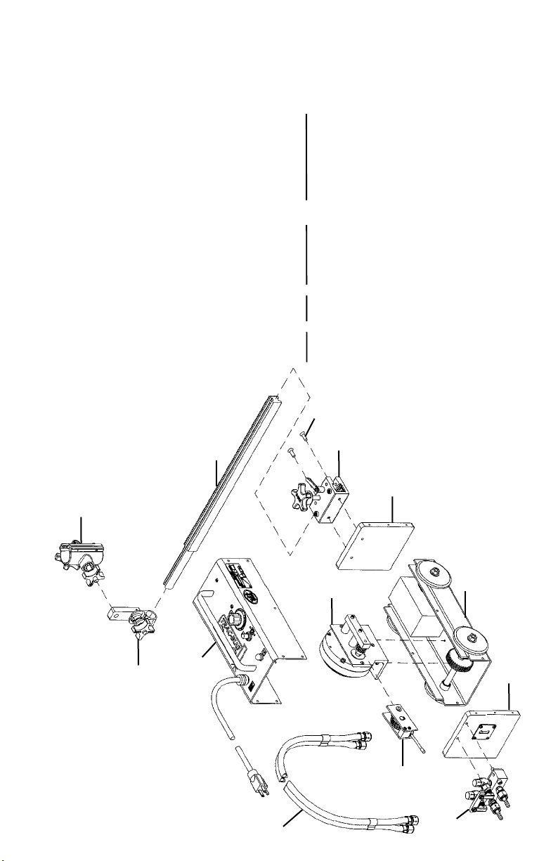
TRAC-BUG / OXY-FUEL
PARTS LIST / TRAC-BUG OXY-FUEL
2 1 BUG-5451 Rack Holder
1 1 BUG-2915 Torch Holder
ITEM QTY PART NO. DESCRIPTION
10 1 TRB-1030 Rear Plate Assembly (page 12)
9 1 TRB-102_ Cover Assembly (page 11)
8 1 TRB-1010 Base Assembly (page 10)
7 1 PAN-1015 Rack 22-5/8"
6 1 MDS-3025 2 Hose Q & A Manifold
5 2 FAS-0957 Flt Hd Soc Scr 1/4-20 x 3/4"
4 1 CIR-1010-3 Twin Hose Assembly
3 1 BUG-9035 Universal Extender
11 1 TRB-1031 Front Plate
14 14 FAS-0124 Flt Hd Scr 8-32 x 3/8"
13 1 TRB-1050 Drive Section (page 14)
12 1 TRB-1040 Clutch Assembly (page 13)
5
7
2
11
1
13
3
9
8
10
12
4
6
7
Page 7
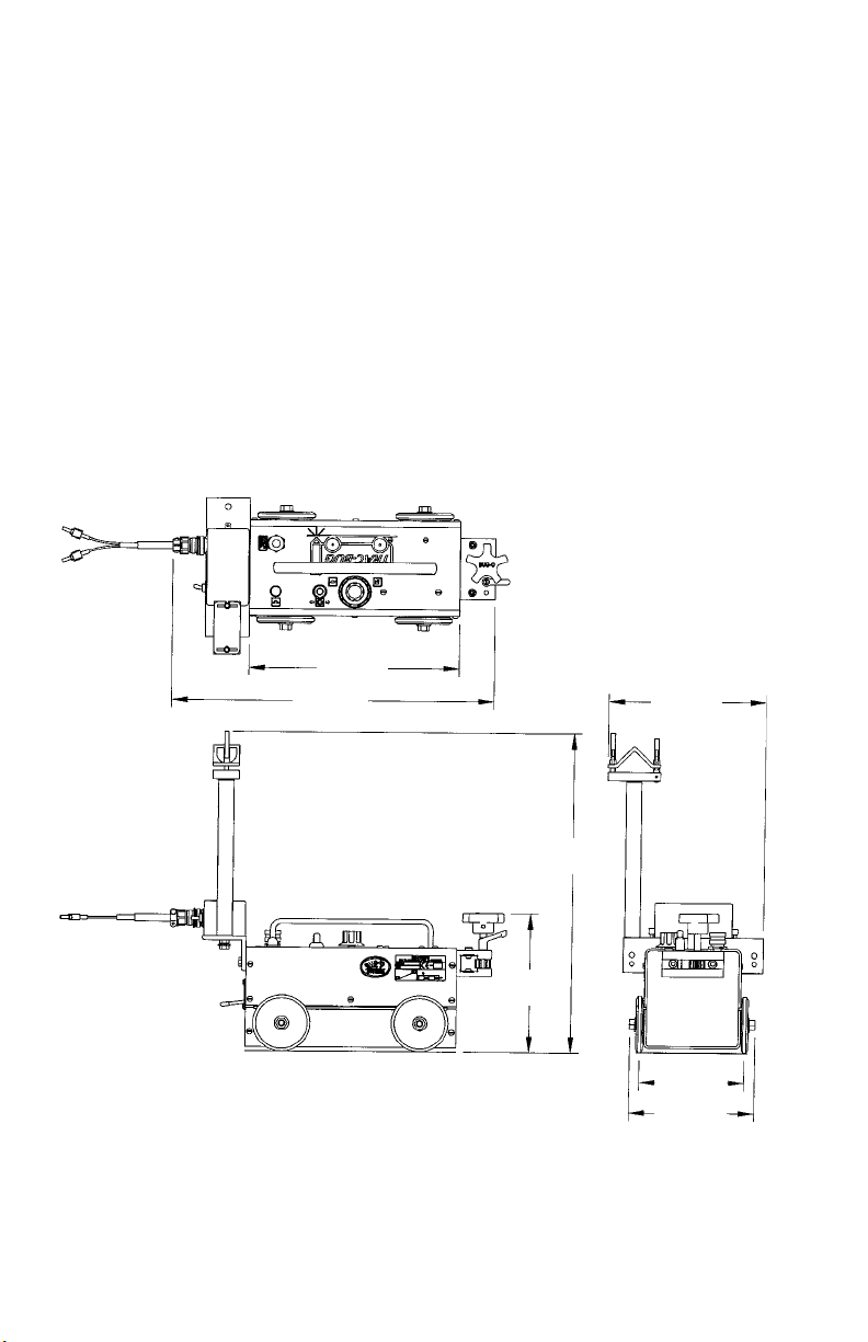
TRAC-BUG / PLASMA
TECHNICAL DATA
Power requirement: 60 watts at rated voltage.
TRB-1500 TRAC-BUG for Plasma 120 VAC/50-60/1
TRB-1502 TRAC-BUG for Plasma 240 VAC/50-60/1
TRB-1504 TRAC-BUG for Plasma 42 VAC/50-60/1
Travel Speed: Innitely variable from 4-72 ipm (100-1800 mm/min)
Net Weight: 33 lbs. (15 kg)
Shipping Weight: 38 lbs. (17 kg)
Dimensions: See below.
12.00"
(305 mm)
18.38"
(467 mm)
9.00"
(229 mm)
18.00"
(470 mm)
8.00"
(204 mm)
6.00"
(152 mm)
7.25"
(185 mm)
8
Page 8

TRAC-BUG / PLASMA
6
5
PARTS LIST / TRAC-BUG PLASMA
ITEM QTY PART NO. DESCRIPTION
3 1 BUG-9035 Universal Extender
2 1 BUG-5451 Rack Holder
1 1 BUG-2915 Torch Holder
6 1 PAN-1015 Rack 22-5/8"
5 2 FAS-0957 Flt Hd Soc Scr 1/4-20 x 3/4"
4 1 BUG-5485 Contactor Box
9 1 TRB-1030 Rear Plate Assembly (page 12)
8 1 TRB-102_ Cover Assembly (page 11)
7 1 TRB-1010 Base Assembly (page 10)
13 14 FAS-0124 Flt Hd Scr 8-32 x 3/8"
12 1 TRB-1050 Drive Section (page 14)
11 1 TRB-1040 Clutch Assembly (page 13)
10 1 TRB-1031 Front Plate
2
1
10
7
12
3
8
9
11
4
9
Page 9

TRB-1010 BASE ASSEMBLY
9
7
10
6
4
3
1
5
11
2
8
10
PARTS LIST
ITEM QTY PART NO. DESCRIPTION
1 4 TRB-1032 Teon Washer
2 4 FAS-1390 3/8-16 Hex Nut
3 4 TRB-1009 Press Bearing
4 1 TRB-1011 Base Panel
5 4 TRB-1014 Steel Wheel
6 2 TRB-1016 Axle
7 2 TRB-1017 Timing Pulley
8 1 TRB-1018 Driven Gear
9 1 TRB-1019 Drive Belt
10 1 TRB-1026 10# Weight
11 4 WAS-0260 3/8" Washer
Page 10

TRB-1020 COVER ASSEMBLY
TRB-1020 120 VAC
TRB-1022 240 VAC
TRB-1024 42 VAC
5
16
12
14
7
4
8
PARTS LIST
ITEM QTY PART NO. DESCRIPTION
* 1 1 BUG-1393 Volt Trap 120 VAC
2 1 CAS-1770 Motor Control Board
3 1 BUG-2255 Toggle Switch
* 4 1 BUG-2923 Circuit Breaker .7 amp
5 1 BUG-2924 Reset Button Seal
* 6 1 BUG-5001 Transformer 120 VAC
* 7 1 BUG-9445 Power Cord 120 VAC
8 1 BUG-9446 Cord Grip
9 1 BUG-9686 Potentiometer Control
10 2 FAS-0114 Pan Hd Scr 6-32 x 3/8"
11 2 FAS-0124 Pan Hd Scr 8-32 x 3/8"
12 2 FAS-0235 Rd Hd Scr 10-24 x 1/2"
13 2 FAS-1320 8-32 Hex Nut
14 1 BUG-5758 Seal, Toggle Switch
15 1 TRB-1021 TRB Cover Panel
16 1 TRB-1025 Handle, 9" Centers
* See Electrical Component Chart on page 15 for 240 VAC and 42 VAC part numbers.
9
3
10
11
15
1
2
6
13
Page 11

TRB-1030 REAR PLATE ASSEMBLY
1
6
3
7
7
4
5
PARTS LIST
ITEM QTY PART NO. DESCRIPTION
1 4 FAS-0112 Pan Hd Scr 6-33 x 1/4"
2 1 FAS-0217 Rnd Hd Scr 6-32 X 3
3 1 TRB-1027 Clutch Spring
4 1 TRB-1028 Clutch Plate
5 1 TRB-1029 Rear Plate
6 1 FAS-1310 Hex Nut 6-32
7 2 WAS-0210 #6 SAE Flat
12 13
Page 12

TRB-1040 CLUTCH ASSEMBLY
1
3
5
2
8
11
9
10
7
3
PARTS LIST
ITEM QTY PART NO. DESCRIPTION
1 1 FAS-0634 Soc Hd Shd 1/4" x 3/8" x 10-24
2 4 FAS-0112 Pan Hd Slt 6-32 x 1/4"
3 2 MUG-1579 Retaining Ring For 3/8" Shaft
4 1 SFX-1216 Bearing Flg 1/4" ID x 3/8" OD x 3/16" LG
5 1 TRB-1035 Clutch Lever
6 1 TRB-1041 Inner Side Plate
7 1 TRB-1042 Outer Side Plate
8 1 TRB-1043 Spacer Block
9 1 TRB-1044 Bearing Flg 3/8" ID x 1/2" OD x 1/4" LG
10 1 TRB-1046 3/8" Diameter Shaft
11 1 TRB-1047 Idler Gear Assembly
4
6
Page 13

TRB-1050 DRIVE SECTION
4
2
9
1
4
5
6
4
7
4
8
3
PARTS LIST
ITEM QTY PART NO. DESCRIPTION
1 1 BUG-1550 Gear Motor 150:1
2 1 BUG-5122 Delrin Washer
3 2 FAS-0527 Soc Hd Cap Scr 8-32 x 3/4"
4 7 FAS-0925 Flt Hd Soc Scr 8-23 x 1/2"
5 1 SFX-1271 Dowel Pin .250" Dia. x .875"
6 1 TRB-1036 Motor Mount Angle
7 2 TRB-1037 Spacer .625" OD x 1.141" LG
8 1 TRB-1038 Clutch Bar
9 1 TRB-1039 Drive Pinion
14 11
Page 14

TRAC-BUG WIRING DIAGRAM
7
6
BLU
WHT/BLU
WHT/BLU
2
3
4
1
ORG
BLU
YEL
TAN
BLU
TAN
RED
BLU
CAS-1770
5
8
M
ELECTRICAL COMPONENT CHART
ITEM DESCRIPTION VOLTAGE
120 VAC 240 VAC 42 VAC
1 Power Cord BUG-9445 GOF-3115 BUG-9442
2 Circuit Breaker BUG-2923 BUG-2952 BUG-2933
3 Transformer BUG-5001 BUG-5002 BUG-5003
4 Volt Trap BUG-1393 BUG-1563 BUG-1393
5 Speed Control CAS-1770
6 Potentiometer w/knob BUG-9686
7 Toggle Sw., F-O-R BUG-2255
8 Gear Motor BUG-1550
15
Page 15

TRAC-BUG TRACK
TRB-1250 FRICTION TRACK 71" (1.8 m)
The TRB-1250 Friction Track is made of steel. The design allows the user
to join multiple sections together for long cuts. This track can only be used
for down-hand applications. The track sections weight 16 lbs. (7.3 kg) each.
7.00"
(178 mm)
6.00"
(152 mm)
.313"
(8 mm)
71.00"
(1800 mm)
16
Page 16

TRB-1160 RADIUS KIT INSTALLATION
The TRB-1160 Radius Kit enables the Trac-Bug to be quickly changed from
a straight line to a circle cutting machine.
Bolt TRB-1153 to the drive unit with the two bolts supplied.
Bolt TRB-1156 to the drive unit with the two bolts supplied. Insert magnet pivot
and rod to machine.
3
4
2
1
PARTS LIST
ITEM QTY PART NO. DESCRIPTION
1 1 TRB-1153 Radius Riser Assembly
2 1 TRB-1156 Radius Block Assembly
3 1 GOF-3128 Rod
4 1 TRB-1165 Magnet Pivot Assembly
5 1 TRB-1155 Radius Arm Attachment (includes items 2, 3 and 4)
NOTE: TRB-1160 can be installed on 2012 models and later. Models from 2011
and earlier require additional machining. Consult the factory for instruction.
17
Page 17

TRB-1153 RADIUS RISER ASSEMBLY
1
5
4
3
Note: Thread lock both FAS-0654
PARTS LIST
ITEM QTY PART NO. DESCRIPTION
1 2 FAS-0557 Soc Hd Cap 1/4-20 x 3/4
2 1 TRB-1154 Radius Riser Block
3 2 BUG-2841 Washer 5/8 OD x 5/16 ID
4 2 BUG-2012 Bearing
5 2 FAS-0654 Soc Hd Shr 5/16 x 3/8 x 1/4-20
2
18
Page 18

TRB-1155 RADIUS ARM ATTACHMENT
3
6
1
4
5
Note: Maintain approx. 1/8" gap
between GOF-3138 & BUG-9012
PARTS LIST
ITEM QTY PART NO. DESCRIPTION
1 1 GOF-3128 Rod
2 1 TRB-1156 Radius Block Assembly
*3 1 GOF-3137 Pivot Point
*4 1 BUG-9012 Locking Collar
*5 2 BUG-2034 Teon Washer 3/4 OD x 3/8 ID x 1/16
*6 1 FAS-0359 Hex Hd Cap Scr 1/4-20 x 1"
*7 1 GOF-3138 Offset Link
*8 1 TRB-1159 Radius Arm Spacer
*9 1 TRB-1158 Sleeve
*10 1 GOF-3133 Magnet
2
7
8
9
10
*Items are part of TRB-1165 Magnet Pivot Assembly
19
Page 19

TROUBLESHOOTING GUIDE
PROBLEM CAUSE REMEDY
Does not run, No power to Check power line supply voltage.
indicator light off. machine. Plug in line cord rmly.
Does not run, Wiring shorts. Disconnect machine and
indicator light off. examine internally;
rewire at fault.
Circuit breaker
tripped. If none found, throw direction
switch to “OFF”, reset breaker
and plug in:
Shorted motor. If breaker does not trip, replace
drive unit.
Faulty speed If breaker trips again, replace
control board. control board.
(OR)
Burned out
transformer. Replace transformer.
Does not run, Bad connection. Check wining connections,
indicator light on. 12 VAC should appear
across secondary of transformer.
Tighten terminal screws on speed
control board.
Faulty speed If DC Volts = 0 across leads to
control board. motor; replace control board.
Unit runs, Faulty speed Replace control board.
but no control control board. (Check connection rst).
over speed.
NOTE: Make sure unit is plugged into correct voltage,
(120 VAC, 240 VAC, 42 VAC) corresponding to Model No. rating.
12 VAC should appear across secondary of transformer in all
TRAC-BUG Units.
20
Page 20

WARRANTY
Limited 3-Year
Warranty
For a period ending one (1) year from the date of invoice, Manufacturer warrants
that any new machine or part is free from defects in materials and workmanship and
Manufacturer agrees to repair or replace at its option, any defective part or machine.
HOWEVER, if the invoiced customer registers the Product Warranty by returning the
Warranty Registration Card supplied with the product within 90 days of the invoice
date, or by registering on-line at www.bugo.com, Manufacturer will extend the warranty period an additional two (2) years which will provide three (3) total years from
the date of original invoice to customer. This warranty does not apply to machines
which, after Manufacture’s inspection are determined by Manufacturer to have been
damaged due to neglect, abuse, overloading, accident or improper usage. All shipping and handling charges will be paid by the customer.
The foregoing express warranty is exclusive and Manufacturer makes no representation or warranty (either express or implied) other than as set forth expressly in
the preceding sentence. Specifically, Manufacturer makes no express or implied
warranty of merchantability or fitness for any particular purpose with respect to any
goods. Manufacturer shall not be subject to any other obligations or liabilities whatsoever with respect to machines or parts furnished by Manufacturer.
Manufacturer shall not in any event be liable to Distributor or any customer for any
loss of profits, incidental or consequential damages or special damages of any kind.
Distributor’s or customer’s sole and exclusive remedy against Manufacturer for any
breach of warranty, negligence, strict liability or any other claim relating to goods delivered pursuant hereto shall be for repair or replacement (at Manufacturer’s option)
of the machines or parts affected by such breach.
Model _____________________________
Serial No. __________________________
Date Purchased: ____________________
Where Purchased: ___________________
Distributor’s Warranty:
In no event shall Manufacturer be liable to Distributor or to any customer thereof for
any warranties, representations or promises, express or implied, extended by Distributor without the advance written consent of Manufacturer, including but not limited
to any and all warranties of merchantability or fitness for a particular purpose and
all warranties, representations or promises which exceed or are different from the
express limited warranty set forth above. Distributor agrees to indemnify and hold
Manufacturer harmless from any claim by a customer based upon any express or
implied warranty by Distributor which exceeds or differs from Manufacturer’s express
limited warranty set forth above.
HOW TO OBTAIN SERVICE:
If you think this machine is not operating properly, re-read the instruction manual
carefully, then call your Authorized BUG-O dealer/distributor. If they cannot give
you the necessary service, write or phone us to tell us exactly what difculty
you have experienced. BE SURE to mention the MODEL and SERIAL numbers.
21
Page 21

NOTES:
22
 Loading...