

Page 1

INSTRUCTIONS
AND
PARTS MANUAL
STW-3000
PROGRAMMABLE
STIFFENER
WELDER
Please record your equipment identication information below for future reference. This information can be
found on your machine nameplate.
Model Number
Serial Number
Date of Purchase
Whenever you request replacement parts or information on this equipment, always supply the information you
have recorded above.
LIT-STW-3000-IPM-1214
Bug-O Systems is guided by honesty, integrity and
ethics in service to our customers and in all we do.
A DIVISION OF WELD TOOLING CORPORATION
280 TECHNOLOGY DRIVE CANONSBURG, PENNSYLVANIA 15317-9564 USA
PHONE: 412-331-1776 http://www.bugo.com FAX: 412- 331- 0383
Page 2
SAFETY
PROTECT YOURSELF AND OTHERS FROM SERIOUS INJURY OR DEATH. KEEP
CHILDREN AWAY. BE SURE THAT ALL INSTALLATION, OPERATION, MAINTENANCE
AND REPAIR PROCEDURES ARE PERFORMED ONLY BY QUALIFIED INDIVIDUALS.
ELECTRIC SHOCK can kill.
1. The equipment is not waterproof.
Using the unit in a wet environment
may result in serious injury. Do not
touch equipment when wet or standing
in a wet location.
2. The unused connectors have power on
them. Always keep the unused
connectors covered with the supplied
protective panels. Operation of the
machine without the protective panels
may result in injury.
3. Never open the equipment without
rst unplugging the power cord or
serious injury may result.
4. Verify the customer-supplied power
connections are made in accordance
with all applicable local and national
electrical safety codes. If none exist,
use International Electric Code (IEC)
950.
5. Never remove or bypass the equipment
power cord ground. Verify the
equipment is grounded in accordance
with all applicable local and national
electrical safety codes. In none exist,
use International Electric Code (IEC)
950.
EQUIPMENT DAMAGE
POSSIBLE.
1. Do not plug in the power cord without
rst verifying the equipment is OFF
and the cord input voltage is the same
as required by the machine or serious
damage may result.
2. Always verify both the pinion and
wheels are fully engaged before
applying power or equipment damage
may occur.
3. Do not leave the equipment
unattended.
4. Remove from the worksite and store
in a safe location when not in use.
FALLING EQUIPMENT
can cause serious
personal injury and
equipment damage.
Faulty or careless user installation is
possible. As a result, never stand or
walk underneath equipment.
READ INSTRUCTIONS.
Read the instruction manual before
installing and using the equipment.
2
MOVING PARTS can
cause serious injury.
1. Never try to stop the pinion from
moving except by removing power
or by using the STOP control.
2. Do not remove any protective panels,
covers or guards and operate
equipment.
Page 3

HIGH FREQUENCY WARNINGS
SPECIAL PRECAUTIONS ARE REQUIRED WHEN USING PLASMA,
TIG OR ANY WELDING PROCESS THAT USES HIGH FREQUENCY
TO STRIKE AN ARC.
WARNING: HIGH FREQUENCY CAN EFFECT MACHINE
OPERATION AND THEREFORE, WELD QUALITY
Read the precautions below before installing and using the equipment.
PRECAUTIONS:
1) Some plasma or welding cables are strong sources of high frequency
interference. NEVER lay a plasma or welding cable across the controls of the
machine.
2) Always physically separate the plasma or welding cable leads from the machine
cables. For example, the plasma or welding cable leads should NEVER be
bundled with a pendant cable or the machine power cord. Maximize the separa-
tion between any machine cables and the plasma or welding cables.
3) Strictly follow the grounding procedures specied for the plasma or welding unit.
NOTE: Some plasma and welding units produce exceptionally large amounts of
high frequency noise. They may require a grounding rod be driven into the earth
within six feet (2 meters) of the plasma or welding unit to become compatible
with an automatic cutting or welding process.
4) If the high frequency is produced using a spark gap, adjust the points so the gap
is as small as possible. The larger the gap, the higher the voltage and the higher
the interference.
5) Some plasma or welding units will inject high frequency interference into the AC
power line. Use separate power line branches whenever possible to power the
plasma or welding source and the machine. Do not plug them into the same
outlet box.
6) High frequency noise may enter the machine through the plasma or welding
supply remote contactor leads. Some plasma and welding sources can produce
noise spikes of up to several thousand volts. These sources are not compatible
with automated cutting and welding equipment. It is recommended that the remote
contactor leads on these plasma or welding sources not be connected to
the machine. An alternate solution is to purchase a separate remote contactor
isolation box.
3
Page 4

STW-3000
PROGRAMMABLE STIFFENER WELDER
INSTRUCTIONS AND PARTS MANUAL
TABLE OF CONTENTS
5 ... Introduction / Setup & Operation
6 ... Controls (Main)
7 ... Controls (Programming Center)
9 ... Technical Data / Dimensions
10 ... STW-3000 Stiffener Welder / Major Components / Parts List
11 ... Wiring Detail
12 ... Wiring Detail / Electrical Component Chart
13 ... STW-2140-L Corner Follower Left / Exploded View / Parts List
14 ... STW-2140-R Corner Follower Right/ Exploded View / Parts List
15 ... STW-2150-L Gun Hinge Left / Exploded View / Parts List
16 ... STW-2150-R Gun Hinge Right / Exploded View / Parts List
17 ... STW-2170-A Capture Wheel Assembly “A” / Exploded View / Parts List
18 ... STW-2170-B Capture Wheel Assembly “B” / Exploded View / Parts List
19 ... STW-2115 Drive Latch / Exploded View / Parts List
20 ... STW-2060 Flow-Meter & Valve Assembly / Exploded View / Parts List
22 ... STW-2120 Drive Unit Assembly / Exploded View
23 ... STW-2120 Drive Unit Assembly / Parts List
24 ... STW-2195 Spool Support Bracket / Exploded View / Parts List
25 ... Accessories (Spools)
26 ... Warranty
4
Page 5

INTRODUCTION:
The Programmable Stiffener Welder mechanizes two wire feeders to weld various types of stiffeners
on one or both sides simultaneously. The unit features independent wire feeder controls for voltage,
wire feed speed, cold wire jog and gas purge. When intermittent stitch welding is required the unit
feature programmable control of weld length and travel speed, skip length, reverse drive crater ll, preweld and post-weld gas purge times. Please see the Technical Data information in this manual for unit
capacities.
SETUP & OPERATION:
(Refer to the Controls Sections pg. 6, 7 and Major Components section pg. 10 in this manual.)
1. Center the unit over the work piece. Connect welding cables and wire feeder control cables for each
feeder to the welding power sources. Connect the welding gas hoses to each Flow Meter/Valve
Assembly. Plug the unit into an available 110 VAC 50/60 Hz power source.
2. Turn power “ON” to both welding power sources. Turn power “ON” to the control panel by toggling
the “ON/OFF” switch on the upper rear right hand side of the control box to the “ON” position.
Ensure both welding torches are active by toggling the Weld Contactor Switches located on each
side of the control box to the “ON” position.
NOTE: Ensure that the Emergency Stop Switch located on the top of the control box is in the released
position. If the Emergency Stop Switch remains depressed, no input power will be supplied to the
unit.
3. Adjust the Capture Wheel Assemblies so that they contact the side of the work. Swing the Drive
Unit into position against the work piece and engage the Drive Latch and tighten to ensure
constant pressure on the work piece between the Drive Assembly, Work Piece and Capture Wheel
Assemblies.
NOTE: Move the unit forward and reverse using the Travel Manual Jog switch located on the front
lower left of the control box to ensure proper tension has been applied by the Drive Latch to move the
unit smoothly along the work piece.
4. Align the left and right Corner Followers and welding guns for the desired weld placement. The
Corner Followers can be adjusted up, down, in and out to achieve the placement you desire.
Coarse torch angle adjustment should be made with the positioning of the corner followers. The
Corner Followers are also equipped with a gun angle adjustment knob to achieve the desired torch
angle and correct position of the welding wire with respect to the joint. Purge the shield gas to each
welding gun by pressing the Shield Gas Purge button located on the left and right sides of
the control panel for each Flow Meter/Valve Assembly.
5. Set all welding parameters. Wire feeder wire speed and voltage are set independently from each
other utilizing the Lincoln LN-10 Controller. All other welding parameters are set using the soft
touch Programming Center. Please refer to the controls section of the manual.
6. When you are ready to begin your weld cycle press the Weld Cycle Start button located on the
control panel below the soft touch Programming Center. To stop the weld cycle press the Weld
Cycle Stop button.
NOTE: In case of emergency, press the Emergency Stop switch located on the top of the control box
to kill all power to the unit including the weld cycle. Once the Emergency Stop switch is returned to the
released position you will need to press the Cycle Start button to resume your cycle.
5
Page 6
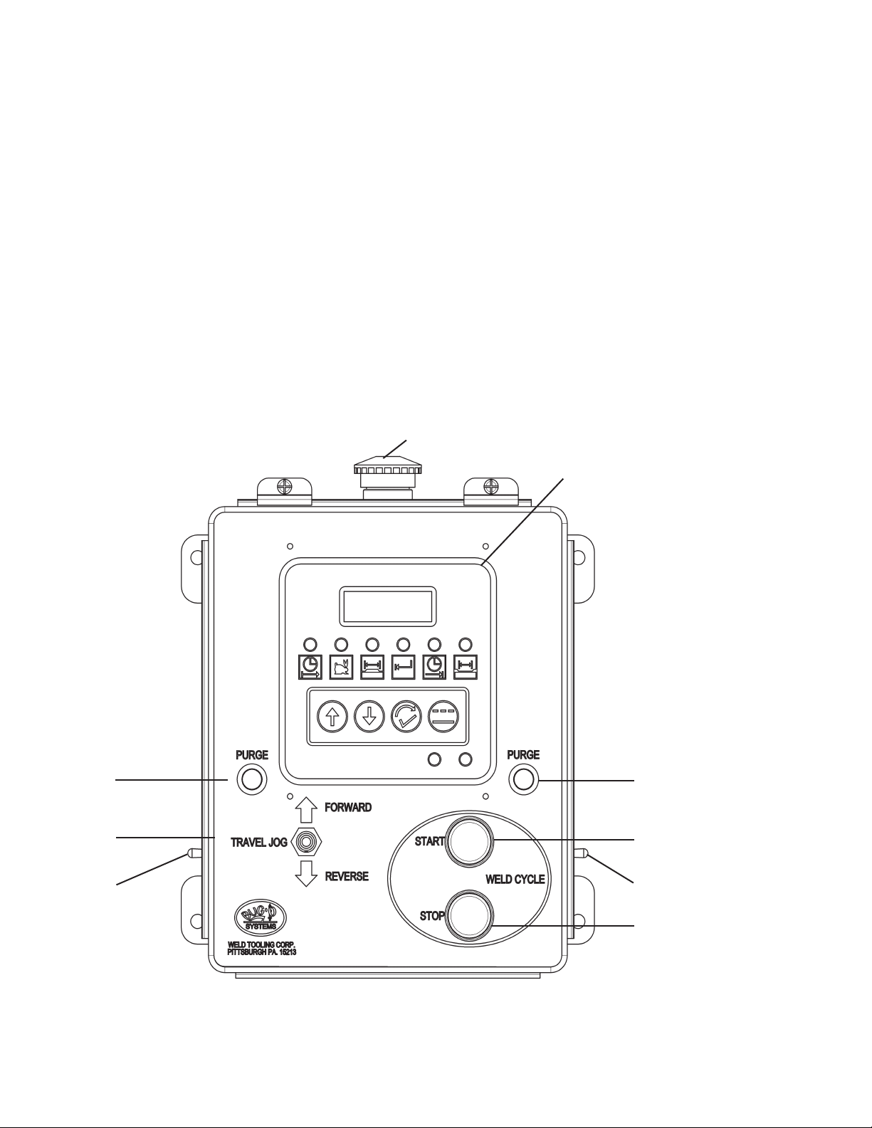
CONTROLS (MAIN):
VOLTAGE CONTROL: Set on Lincoln LN-10 Control.
WIRE SPEED CONTROL: Set on Lincoln LN-10 Control.
WIRE JOG: Jog wire forward and reverse using the controls on the Lincoln LN-10 Control.
WELD CONTACTOR ON/OFF SWITCH: Allows operator to turn the contactor on or off for the
assigned welding torch.
SHIELD GAS PURGE: Allows operator to activate shield gas solenoid to purge welding gun and
check the gas rate on the assigned regulators.
MAIN WELD CYCLE START: Initiates automated weld cycle.
MAIN WELD CYCLE STOP: Halts automated weld cycle.
TRAVEL MANUAL JOG: Allows operator to move the unit forward or backward without welding.
EMERGENCY STOP: When pressed causes all functions to stop.
PROGRAMMING CENTER: See controls for programming center pg. 7.
Emergency Stop
Shield Gas
Purge (A)
Travel
Manual
Jog
Weld
Contactor
Switch A
Programming Center
Shield Gas
Purge (B)
Main Weld
Cycle Start
Weld
Contactor
Switch B
Main Weld
Cycle Stop
6
Page 7

CONTROLS (PROGRAMMING CENTER):
DIGITAL DISPLAY: Visual display to supply welding motion information to operator.
SHIELDING GAS PREFLOW: Programmable time to allow the ow of shielding gas prior to striking
the arc.
TRAVEL SPEED: Speed at which the unit moves during welding.
WELD LENGTH: Distance the unit travels forward while welding in Skip mode.
BACKUP DISTANCE: Distance the unit travels in reverse after completed weld length.
SHIELDING GAS POSTFLOW: Programmable time to allow the ow of shielding gas after the arc
has extinguished.
SKIP LENGTH: Distance between welds. (Must include backup distance).
INCREASE VALUE: Pressing this button increases the value shown in the digital display.
DECREASE VALUE: Pressing this button decreases the value shown in the digital display.
FUNCTION SELECT: Allows the user to cycle through the welding programming functions.
SKIP/CONTINUOUS MODE SELECT: Allows the user to select skip mode or continuous mode for
the welding operation.
SKIP WELD INDICATOR LIGHT: When illuminated the machine will weld in skip mode.
CONTINUOUS WELD INDICATOR LIGHT: When illuminated the machine will weld in continuous
mode.
Note: It is possible to change from Continuous to Skip welding “on-the-y”. To change modes, press
the Continuous/Skip Select button. If the machine is making a continuous weld, the backup function
and postow will occur immediately. The machine will move the programmed skip distance and
proceed to make the programmed skip welds. If the machine is making a skip weld, the machine will
continue to weld until the Continuous/Skip Select button or the Stop button is pressed.
PUDDLE DELAY:
There are two internal settings in the Control Module that do not appear in the normal setting
selection on the control panel keypad/display. These are time delays at weld start and stop, when
the wire feed is on but travel is stopped, in order to allow for puddle buildup.
To set the time delays:
1. Power off, (power switch on back of control box); hold Cycle Stop button in, and turn power
on. Release Stop button. LED No.1 and 3 should light; and the display shows the start puddle
build time.
2. Adjust delay time as required using UP and DOWN arrow buttons.
3. Briey push Function Select (cycle settings) button. LED No. 3 and 5 should light, and display
shows the end crater ll time.
4. Adjust delay time as required.
5. Push Function Select button again, then power off.
6. Power on to operate machine as usual, now with new settings in place.
7
Page 8
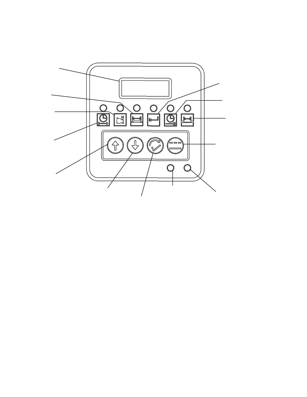
CONTROLS (PROGRAMMING CENTER CONT’D.):
Digital Readout
Weld Length
Travel Speed
Backup Distance
Postow Time
Skip Length
Preow Time
Increase Value
Decrease Value
Function Select
Skip Weld
Indicator
Continuous/Skip
Select
Continuous Weld
Indicator
8
Page 9

TECHNICAL DATA:
Programmable Weld/Skip Travel Speed: 0"-36" ipm (0-900mm/min)
Programmable Reverse Drive Crater Fill: 0"-1" (0-25mm)
Programmable Pre-Weld/Post Weld Gas Purge: 0-10 seconds
Net Weight: 250 lbs. (113 kg)
Stiffener Size Range: Height 4"-18" (102-457mm)
Width 4"-12" (102-305mm)
Wire Spool Capacity: 10, 20, 60 lbs. each side
DIMENSIONS:
23.000"
(58.42 cm)
48.657"
(123.6 m)
52.063"
(132.2 cm)
25.470"
(64.7 cm)
9
Page 10

STW-3000 STIFFENER WELDER / MAJOR COMPONENTS / PARTS LIST
17
1
13
10
12
3
13
2
11
14
13
4
6
20
10
8
7
5
15
13
10
9
18
16
19
16
ITEM QTY PART NO. DESCRIPTION
1 1 Lifting Plate / Control Mount
2 1 Lincoln DM-10 Feeder
3 2 Lincoln LN-10 Wire Feeder Control
4 1 STW-2140-L Corner Follower Left
5 1 STW-2140-R Corner Follower Right
6 1 STW-2150-L Gun Hinge Left
7 1 STW-2150-R Gun Hinge Right
8 1 STW-2170-A Capture Wheel Assy. “A”
9 1 STW-2170-B Capture Wheel Assy. “B”
10 4 STW-2142 3" Phenolic Caster
11 1 STW-2115 Drive Latch
12 2 STW-2060 Flow Meter / Valve Assy.
13 2 STW-2190-18 Leg 18"
14 1 STW-2066 Left Leg Support
15 1 STW-2067 Right Leg Support
16 2 STW-2151 Wheel Mt. Plt.
17 1 STW-2054 Deck Plt.
18 1 STW-2120 Drive Unit
19 1 STW-2195 Spool Support Bracket
20 1 STW-1050 STW Motion Control Box
10
Page 11

WIRING DETAIL
See Electrical Component Chart pg. 12
11
Page 12

WIRING DETAIL / ELECTRICAL COMPONENT CHART
ELECTRICAL COMPONENT CHART
ITEM PART # DESCRIPTION
CB1 BUG-2923 .7 AMP CIRCUIT BREAKER
PC1 BUG-1770 MOTOR CONTROL BOARD
PC2 PCB-2231 RELAY BOARD
PC3 STW-2235 CONTROL MODULE
PM1 BUG-9486 PANEL CONNECTOR, 2-T,M
PM2 BUG-9486 PANEL CONNECTOR, 2-T,M
PM3 CON-06RP04F SHELL 18, RECEPTACLE, PANEL
PM4 CON-06RP04F SHELL 18, RECEPTACLE, PANEL
PM5 CON-04RP03M SHELL 16S, RECEPTACLE, PANEL
PM6 BUG-9856 PANEL CONNECTOR, 2-T,F
SW1 SWT-FPF3 ROUND, FLUSH, GREEN SWITCH
SW2 SWT-FPF4 ROUND, FLUSH, RED SWITCH
SW3 BUG-2255 TOGGLE SWITCH, DPDT, ON OFF ON
SW4 SWT-1111 NOR, OPEN PUSH BUTTO, BLACK
SW5 SWT-1111 NOR, OPEN PUSH BUTTO, BLACK
SW6 SWT-5225 TOGGLE SWITCH
SW7 SWT-5225 TOGGLE SWITCH
SW8 ARM-2279 TOGGLE SWITCH, DPST, ON NONE ON
SW9 SWT-EPFH ROUND, MUSHROOM, LATCHINH, RED SWITCH
T1 BUG-5001 120 VAC - 20VAC TRANSFORMER
12
Page 13

STW-2140-L CORNER FOLLOWER LEFT / EXPLODED VIEW / PARTS LIST
7
8
4
17
9
10
2
15
6
3
11
18
16
18
5
12
14
13
1
ITEM QTY PART NO. DESCRIPTION
1 1 WPD-2041 Clamp Block
2 1 BUG-2032 Knob, Black
3 4 BUG-2593 Glide “Flat”
4 1 FAS-0535 Soc Hd Cap 10-24 x 1/2
5 2 FAS-0654 Soc Hd Shr 5/16x3/8x1/4-20
6 2 FAS-0957 1/4-20 x 3/4 Flat Hd Socket
7 2 MUG-1515 Collar
8 1 PAN-1236 Slide Assembly Welded Post
9 1 PAN-2125 Mounting Arm Assembly
10 1 PAN-2131-R Mounting Plate, Left
11 1 PAN-2133-R Slide Plate, Left
12 1 PAN-2134 Screw Retainer
13 1 PAN-2135 Screw Block
14 1 PAN-2137 External Retaining Ring
15 1 PAN-3105 Adjusting Screw
16 1 RPS-0113 Roll Pin 3/32 x 7/16
17 1 WAS-0230 #10 SAE Flat
18 4 WAS-0255 Oil Impreg. Bronze Thrust Wash
19 1 BUG-2708-1.5 Clamp W/1.5" Shaft
19
13
Page 14

STW-2140-R CORNER FOLLOWER RIGHT / EXPLODED VIEW / PARTS LIST
7
8
19
10
6
3
11
14
13
18
5
1
12
18
15
16
2
17
9
ITEM QTY PART NO. DESCRIPTION
1 1 WPD-2041 Clamp Block
2 1 BUG-2032 Knob, Black
3 4 BUG-2593 Glide “Flat”
4 1 FAS-0535 Soc Hd Cap 10-24 x 1/2
5 2 FAS-0654 Soc Hd Shr 5/16x3/8x1/4-20
6 2 FAS-0957 1/4-20 x 3/4 Flat Hd Socket
7 2 MUG-1515 Collar
8 1 PAN-1236 Slide Assembly Welded Post
9 1 PAN-2125 Mounting Arm Assembly
10 1 PAN-2131-R Mounting Plate, Right
11 1 PAN-2133-R Slide Plate, Right
12 1 PAN-2134 Screw Retainer
13 1 PAN-2135 Screw Block
14 1 PAN-2137 External Retaining Ring
15 1 PAN-3105 Adjusting Screw
16 1 RPS-0113 Roll Pin 3/32 x 7/16
17 1 WAS-0230 #10 SAE Flat
18 4 WAS-0255 Oil Impreg. Bronze Thrust Wash
19 1 BUG-2708-1.5 Clamp W/1.5" Shaft
4
14
Page 15

STW-2150-L GUN HINGE LEFT / EXPLODED VIEW / PARTS LIST
13
2
4
7
3
1
10
15
12
9
16
5
8
6
11
14
13
ITEM QTY PART NO. DESCRIPTION
1 1 STW-2151 Wheel/Hinge Plate
2 1 STW-2152 Hinge Plate “A”
3 1 STW-2154 Hinge Plate “C”
4 1 STW-2155 Hinge Rod
5 1 STW-2156 Mounting Bar
6 1 STW-2158 Vertical Mounting Rod
7 1 STW-2159 SS Pin 1/8" Diameter x 1"
8 1 STW-2160 Clamp Block (Round/Square)
9 1 STW-2168 Hinge Plate “E”
10 1 STW-2178 Knurled Knob Plunger
11 6 FAS-0559 Soc Hd Cap Scr 1/4-20 x 1"
12 1 FAS-0599 Soc Hd Cap 3/8-16 x 1"
13 2 FAS-2693 Soc Hd Shr 1/2" x 1" x 3/8-16
14 1 FAS-0999 Flt Hd Soc 3/8-16 x 1"
15 1 FAS-1301 Hex Nut 1/2-13
16 1 STW-2165 Clamp Block LG (Round/Square)
15
Page 16

STW-2150-R GUN HINGE RIGHT / EXPLODED VIEW / PARTS LIST
16
11
10
15
12
9
5
8
6
3
7
13
2
4
1
14
13
ITEM QTY PART NO. DESCRIPTION
1 1 STW-2151 Wheel/Hinge Plate
2 1 STW-2152 Hinge Plate “A”
3 1 STW-2153 Hinge Plate “B”
4 1 STW-2155 Hinge Rod
5 1 STW-2156 Mounting Bar
6 1 STW-2158 Vertical Mounting Rod
7 1 STW-2159 SS Pin 1/8" Diameter x 1"
8 1 STW-2160 Clamp Block (Round/Square)
9 1 STW-2167 Hinge Plate “D”
10 1 STW-2178 Knurled Knob Plunger
11 6 FAS-0559 Soc Hd Cap Scr 1/4-20 x 1"
12 1 FAS-0599 Soc Hd Cap 3/8-16 x 1"
13 2 FAS-2693 Soc Hd Shr 1/2" x 1" x 3/8-16
14 1 FAS-0999 Flt Hd Soc 3/8-16 x 1"
15 1 FAS-1301 Hex Nut 1/2-13
16 1 STW-2165 Clamp Block LG (Round/Square)
16
Page 17

STW-2170-A CAPTURE WHEEL ASSEMBLY “A” / EXPLODED VIEW /
PARTS LIST
2
10
1
12
3
5
8
7
11
6
9
13
ITEM QTY PART NO. DESCRIPTION
1 1 STW-2135 Hinge Bearing Block
2 1 STW-2138 Shaft Collar 3/4" I.D.
3 1 STW-2173 Follower Hinge
4 1 STW-2174 Five Lobe Knob / Insert
5 1 STW-2175-A Female Tube Weldment
6 1 STW-2179 2" Caster / Iron Wheel
7 1 STW-2180 Male Tube Weldment
8 1 FAS-0454-Cone Set Scr 1/4-20 x 3/8" Cone Point
9 4 FAS-0555 Soc Hd Cap Scr 1/4-20 x 1/2"
10 4 FAS-2554 Soc Hd Cap Scr 1/4-20 x 1-3/4"
11 1 FAS-0455-HDP Set Scr 1/4-20 x 1/2" Half Dog
12 1 SPR-1001-LH Left Follower Spring
13 1 STW-2171 Follower Stud
4
17
Page 18

STW-2170-B CAPTURE WHEEL ASSEMBLY “B” / EXPLODED VIEW / PARTS
LIST
2
10
1
12
3
13
5
8
7
6
11
9
4
ITEM QTY PART NO. DESCRIPTION
1 1 STW-2135 Hinge Bearing Block
2 1 STW-2138 Shaft Collar 3/4" I.D.
3 1 STW-2173 Follower Hinge
4 1 STW-2174 Five Lobe Knob/Insert
5 1 STW-2175-B Female Tube Weldment
6 1 STW-2179 2" Caster/Iron Wheel
7 1 STW-2180 Male Tube Weldment
8 1 FAS-0454-Cone Set Scr 1/4-20 x 3/8" Cone Point
9 4 FAS-0555 Soc Hd Cap Scr 1/4-20 x 1/2"
10 4 FAS-2554 Soc Hd Cap Scr 1/4-20 x 1-3/4"
11 1 FAS-0455-HDP Set Scr 1/4-20 x 1/2" Half Dog
12 1 SPR-1001-RH Right Follower Spring
13 1 STW-2171 Follower Stud
18
Page 19

STW-2115 DRIVE LATCH / EXPLODED VIEW / PARTS LIST
1
6
5
1
6
3
2
4
ITEM QTY PART NO. DESCRIPTION
1 4 FAS-0557 Soc Hd Cap Scr 1/4-20 x 3/4"
2 1 STW-2116 Drive Latch Weldment
3 1 STW-2118 Screw 1/2-13 x 3-1/2"
4 1 STW-2119 Level Mount
5 1 STW-2174 Five Lobe Knob Insert 1/2-13 RT
6 4 WAS-0240 1/4" SAE Washer
19
Page 20

STW-2060 FLOW-METER & VALVE ASSEMBLY / EXPLODED VIEW / PARTS
LIST
13
REAR
3
2
8
10
11
9
1
14
7
4 5 6 12
ITEM QTY PART NO. DESCRIPTION
0
1 1 ARV-1113 1/4 NPT 90
Street Elbow
2 1 BUG-9096 Outlet Bushing, Oxygen, Right
3 1 BUG-9102 Magnetic Valve For Use With Oxygen
4 1 CIR-1012 Hose Nut, Oxygen, Right Hand
5 1 CIR-1013 1/4" Hose Nipple
6 1 CIR-1016 Hose Clamp 9/16" Crimp Type
7 2 FAS-0547 Soc Hd Cap Scr 10-30 x 3/4"
8 1 STW-2061 Argon Flowmeter
9 1 STW-2062 Modied Cord Grip
10 1 STW-2063 1/4" I.D. Hose Barb
11 1 STW-2064 Inert Gas Male RH
12 2 STW-2065 Clamp 2-Ear 8-11mm
13 1 CON-PS04M Plug, Straight, 4 Pin, Male
14 2 AFR-1015 Spacer Washer
NS 26" 1000-4-002 1/4" I.D. x 3/8" O.D. Tube
NS 36" MUG-1581 #2 Black Fiberglass Sleeving
20
Page 21

THIS PAGE IS INTENTIONALLY LEFT BLANK.
21
Page 22

STW-2120 DRIVE UNIT ASSEMBLY / EXPLODED VIEW
11
15
5
20
16
7
17
8
11
22
12
21
10
13
1
3
9
4
14
19
2
6
18
22
Page 23

STW-2120 DRIVE UNIT ASSEMBLY / PARTS LIST
ITEM QTY PART NO. DESCRIPTION
1 1 BUG-1595 Gear Motor (100:1)
2 1 STW-2139 Drive Unit Shaft
3 1 BUG-9856 Panel Connector 2-T, Female
4 4 FAS-0205 Rnd Hd Scr 4-40 x 1/2"
5 1 FAS-0410 Set Scr 6-32 x 1/8" Cup Point
6 1 FAS-0454 Set Scr 1/4-20 x 3/8" Cup Point
7 1 FAS-0527 Soc Hd Cap Scr 8-32 x 3/4"
8 2 FAS-0529 Soc Hd Cap Scr 8-32 x 1"
9 4 FAS-0559 Soc Hd Cap Scr 1/2-20 x 1"
10 4 FAS-1305 Hex Nut 4-40
11 4 FAS-2553 Soc Hd Cap Scr 1/4-20 x 1-1/2"
12 4 FAS-2554 Soc Hd Cap Scr 1-20 x 1-3/4"
13 1 GOF-3014 Drive Pinion w/Key & Set Screw
14 1 STW-2121 Drive Unit Bottom Cover
15 1 STW-2122 Drive Unit Top Cover
16 1 STW-2123 Drive Shaft
17 1 STW-2125 Drive Gear Assembly
18 1 STW-2128 Drive Unit Mounting Block
19 1 SPR-1002-LH Spring
20 1 STW-2130 Drive Wheel Assy.
21 1 STW-2135 Hinge Bearing Assy.
22 1 STW-2138 Locking Collar
23 2 GOF-3036 QD Female, Fully Insulated (not shown)
23
Page 24

STW-2195 SPOOL SUPPORT BRACKET / EXPLODED VIEW / PARTS
LIST
6
3
2
4
5
7
1
4
2
ITEM QTY PART NO. DESCRIPTION
1 6 FAS-0557 Hex Hd Cap Scr 1/4-20 x 3/4"
2 8 FAS-0579 Hex Hd Cap Scr 5/16-18 x 1"
3 4 FAS-0599 Hex Hd Cap Scr 3/8-16 x 1"
4 2 STW-2069 Spool Mount Plate
5 1 STW-2196 Mount Plate
6 1 STW-2197 Guage Mount Plate
7 1 STW-2198 Cable Mount
24
Page 25

ACCESSORIES (SPOOLS):
10 lb. Spool Kit
The 10 lb. spool kit accepts 10 lb. spools of wire
and mounts to the spool mounting bracket on the
rear of the welding unit.
Order #STW-2100
Comes in quantities of 1.
30 lb. Spool Kit
The 30 lb. spool kit accepts 30 lb. spools of wire
and mounts to the spool mounting bracket on the
rear of the welding unit.
Order #WFU-1041
Comes in quantities of 1.
60 lb. Spool Kit
The 60 lb. spool kit accepts 60 lb. spools of wire
and mounts to the spool mounting bracket on the
rear of the welding unit.
Order #BUG-3293
Comes in quantities of 1.
25
Page 26

WARRANTY
Model _____________________________
Limited 3-Year Warranty*
For a period ending one (1) year from the date of invoice, Manufacturer warrants that any new machine or part is free
from defects in materials and workmanship and Manufacturer agrees to repair or replace at its option, any defective part
or machine. HOWEVER, if the invoiced customer registers the Product Warranty by returning the Warranty Registration
Card supplied with the product within 90 days of the invoice date, or by registering on-line at www.bugo.com, Manufacturer
will extend the warranty period an additional two (2) years which will provide three (3) total years from the date of original
invoice to customer. This warranty does not apply to machines which, after Manufacture’s inspection are determined by
Manufacturer to have been damaged due to neglect, abuse, overloading, accident or improper usage. All shipping and
handling charges will be paid by the customer.
The foregoing express warranty is exclusive and Manufacturer makes no representation or warranty (either express or
implied) other than as set forth expressly in the preceding sentence. Specifically, Manufacturer makes no express or
implied warranty of merchantability or fitness for any particular purpose with respect to any goods. Manufacturer shall not
be subject to any other obligations or liabilities whatsoever with respect to machines or parts furnished by Manufacturer.
Manufacturer shall not in any event be liable to Distributor or any customer for any loss of profits, incidental or consequential damages or special damages of any kind. Distributor’s or customer’s sole and exclusive remedy against Manufacturer
for any breach of warranty, negligence, strict liability or any other claim relating to goods delivered pursuant hereto shall be
for repair or replacement (at Manufacturer’s option) of the machines or parts affected by such breach.
Distributor’s Warranty:
Serial No. __________________________
Date Purchased: ____________________
Where Purchased:___________________
In no event shall Manufacturer be liable to Distributor or to any customer thereof for any warranties, representations or
promises, express or implied, extended by Distributor without the advance written consent of Manufacturer, including but
not limited to any and all warranties of merchantability or fitness for a particular purpose and all warranties, representations
or promises which exceed or are different from the express limited warranty set forth above. Distributor agrees to indemnify
and hold Manufacturer harmless from any claim by a customer based upon any express or implied warranty by Distributor
which exceeds or differs from Manufacturer’s express limited warranty set forth above.
HOW TO OBTAIN SERVICE:
If you think this machine is not operating properly, re-read the instruction manual carefully, then call your Authorized
BUG-O dealer/distributor. If they cannot give you the necessary service, write or phone us to tell us exactly what
difculty you have experienced. BE SURE to mention the MODEL and SERIAL numbers.
*Bug-O System’s warranty applies to Bug-O components only. Where other brands of power sources, wire feeders or sub
components are a part of Bug-O Equipment, please refer to that specific Manufacturer’s manual for warranty specifications
on their components.
26
 Loading...