

Page 1

INSTRUCTIONS
AND
PARTS MANUAL
K-BUG 1200
K-BUG 1200
K-BUG 1202
K-BUG 1204
Please record your equipment identication information below for future reference. This information can be found
on your machine nameplate.
Model Number
Serial Number
Date of Purchase
Whenever you request replacement parts or information on this equipment, always supply the information you
have recorded above.
LIT-KBUG-1200-IPM-0115
Bug-O Systems is guided by honesty, integrity and
ethics in service to our customers and in all we do.
A DIVISION OF WELD TOOLING CORPORATION
280 TECHNOLOGY DRIVE CANONSBURG, PENNSYLVANIA 15317-9564 USA
PHONE: 412-331-1776 http://www.bugo.com FAX: 412- 331- 0383
Page 2
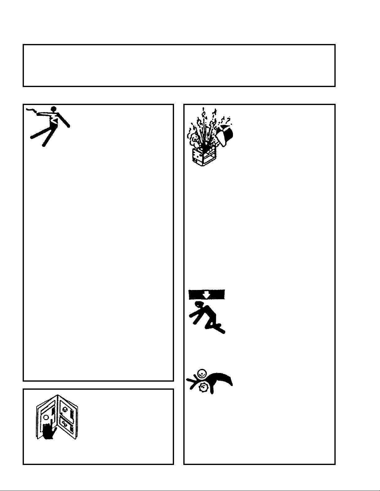
SAFETY
PROTECT YOURSELF AND OTHERS FROM SERIOUS INJURY OR DEATH.
KEEP CHILDREN AWAY. BE SURE THAT ALL INSTALLATION, OPERATION,
MAINTENANCE AND REPAIR PROCEDURES ARE PERFORMED ONLY BY
QUALIFIED INDIVIDUALS.
ELECTRIC SHOCK can kill.
1) The equipment is not waterproof. Using
the unit in a wet environment may result
in serious injury. Do not touch equipment
when wet or standing in a wet location.
2) The unused connectors have power on
them. Always keep the unused connec tors covered with the supplied protective
panels. Operation of the machine without
the protective panels may result in injury.
3) Never open the equipment without rst
unplugging the power cord or serious
injury may result.
4) Verify the customer-supplied power
connections are made in accordance
with all applicable local and national
electrical safety codes. If none exist,
use International Electric Code (IEC)
950.
5) Never remove or bypass the equipment
power cord ground. Verify the equipment
is grounded in accordance with all appli cable local and national electrical safety
codes. If none exist, use International
Electric Code (IEC) 950.
EQUIPMENT DAMAGE
POSSIBLE.
1) Do not plug in the power cord without rst
verifying the equipment is OFF and the
cord input voltage is the same as required
by the machine or serious damage may
result.
2) Always verity both the pinion and wheels
are fully engaged before applying power
or equipment damage may occur.
3) Do not leave the equipment unattended.
4) Remove from the work site and store in
a safe location when not in use.
FALLING EQUIPMENT
can cause serious
personal injury and
equipment damage.
Faulty or careless user installation is
possible. As a result, never stand or walk
underneath equipment.
MOVING PARTS can
cause serious injury.
1) Never try to stop the pinion from moving
except by removing power or by using the
READ INSTRUCTIONS.
Read the instruction manual before
installing and using the equipment.
2
STOP control.
2) Do not remove any protective panels,
covers or guards and operate equipment.
Page 3

HIGH FREQUENCY WARNINGS
SPECIAL PRECAUTIONS ARE REQUIRED WHEN USING PLASMA, TIG OR ANY
WELDING PROCESS THAT USES HIGH FREQUENCY TO STRIKE AN ARC.
WARNING: HIGH FREQUENCY CAN EFFECT MACHINE
OPERATION AND THEREFORE, WELD QUALITY.
Read the precautions below before installing and using the equipment.
PRECAUTIONS:
1) Some plasma or welding cables are strong sources of high frequency interference.
NEVER lay a plasma or welding cable across the controls of the machine.
2) Always physically separate the plasma or welding cable leads from the machine cables. For
example, the plasma or welding cable leads should NEVER be bundled with a pendant
cable or the machine power cord. Maximize the separation between any machine cables and
the plasma or welding cables.
3) Strictly follow the grounding procedures specied for the plasma or welding unit.
NOTE: Some plasma and welding units produce exceptionally large amounts of high
frequency noise. They may require a grounding rod be driven into the earth within six feet
(2 meters) of the plasma or welding unit to become compatible with an automatic cutting or
welding process.
4) If the high frequency is produced using a spark gap, adjust the points so the gap is as small
as possible. The larger the gap, the higher the voltage and the higher the interference.
5) Some plasma or welding units will inject high frequency interference into the AC power line.
Use separate power line branches whenever possible to power the plasma or welding source
and the machine. Do not plug them into the same outlet box.
6) High frequency noise may enter the machine through the plasma or welding supply remote
contactor leads. Some plasma and welding sources can produce noise spikes of up to several
thousand volts. These sources are not compatible with automated cutting and welding
equipment. It is recommended that the remote contactor leads on these plasma or welding
sources not be connected to the machine. An alternate solution is to purchase a separate
remote contactor isolation box.
3
Page 4

K-BUG 1200
K-BUG 1200, K-BUG 1202, KBUG-1204
INSTRUCTIONS AND PARTS MANUAL
TABLE OF CONTENTS
PAGE
5 ..........Introduction
5 ..........Features
5 ..........Technical Data
5 ..........Dimensions
6 ..........Illustration of Typical Applications
6 ..........User Interface
7 ..........Welding Modes
7 ..........Intermittent Welding
7 ..........Continuous Welding (Intermittent Welding Lock-Out)
8 ..........Time Settings
8 ..........Stop Sensor Operation
9 ..........Global Parameters
9 ..........Converting Units
10 .........Installation and Operation
10 .........Cable Interconnect Diagram
11 .........Maintenance
11 .........Troubleshooting
12 .........Troubleshooting, Cont’d.
13 .........K-BUG 1200 Assembly View
14 .........K-BUG 1200 Wiring Diagram
15 .........KBUG-1210 Carriage Assembly / Exploded View
16 .........KBUG-1210 Carriage Assembly / Parts List
17 .........KBUG-1060 Guide Arms / Exploded View / Parts List
17 .........KBUG-1230 Angle Slide Assembly / Exploded View / Parts List
18 .........KBUG-1100 Torch Clamp Assembly / Exploded View / Parts List
18 .........KBUG-1120 Control Panel Assembly / Exploded View / Parts List
19 .........SBG-450-_-__-_ Gun & Cable Assembly / Exploded View / Parts List
20 .........Accessories
21 .........Warranty
4
Page 5
INTRODUCTION
The K-BUG 1200 is a compact, light weight unit designed to mechanize horizontal llet welding. The
machine is capable of performing continuous and intermittent (stitch) welds.
FEATURES
• Compact - 12.4 x 7.8 x 11.1 in (31.4 x 19.8 x 28.1 cm)
• Lightweight - 13 lb (5.9 kg)
• Continuous and intermittent welds
• Digital speed display
• Precision speed control for consistent weld quality
• User adjustable time settings for puddle build-up, pause time and crater-ll
• Will climb up to a 75° incline
• Drive wheels rated to 400 °F (204 °C)
TECHNICAL DATA
Power Input: K-BUG 1200 120VAC / 50-60 Hz / 1 Phase
K-BUG 1202 240VAC / 50-60 Hz / 1 Phase
K-BUG 1204 42VAC / 50-60 Hz / 1 Phase
Weight: 13 lb (5.9 kg)
Drive Motor: 24 VDC, 12 W, 5000 RPM
Travel Speed: 1.5 - 37 in/min (3 - 95 cm/min)
Torch Angle: Adjustable
Running Angle: 90°
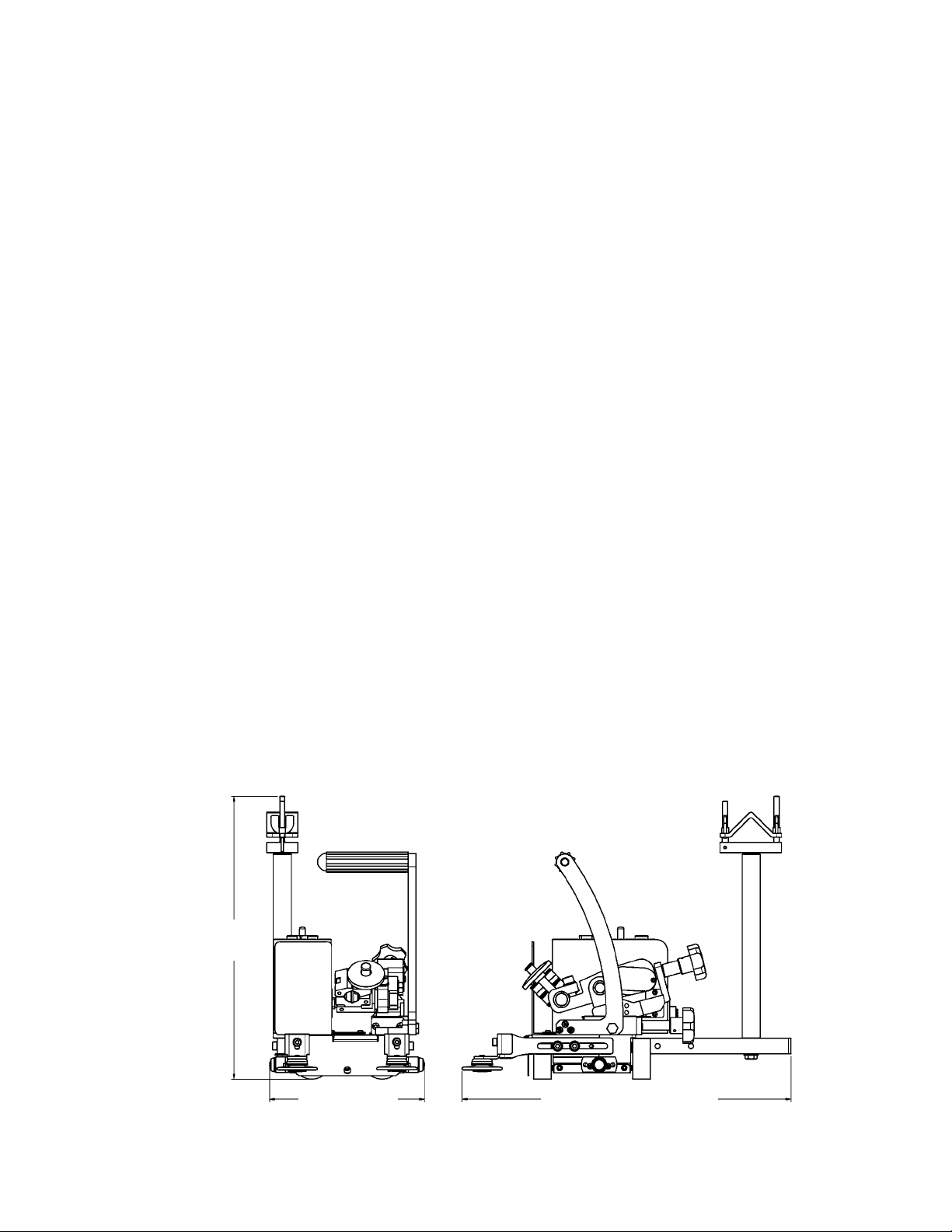
DIMENSIONS
13.8"
(351 mm)
7.75"
(196.85 mm)
9.5" (min) - 16" (max)
(241 - 406 mm)
5
Page 6

ILLUSTRATION OF TYPICAL APPLICATIONS
USER INTERFACE
1. Cycle Start Button - Push button to initiate
weld cycle. Weld contact will close, according to
time settings, if the Weld Switch is set to Auto,
the carriage will travel in the direction selected
by the Travel Direction Switch.
2. Cycle Stop Button - Push button to stop
welding cycle.
3. Travel Direction Switch - Set switch to
determine direction of carriage travel.
4. Speed Adjustment Dial - Rotate knob to adjust
carriage travel speed. Turning clockwise (right)
will INCREASE speed.
NOTE: Travel Speed Adjustment Knob is also
used for setting the INTERMITTENT WELDING
function (pg.7) and the time settings.
5. Weld Auto / Off Contactor - When switched to
AUTO, weld contact will close with cycle start.
Switched to the right, weld contact will remain
open upon cycle start.
6. Digital Speed Display - Numerically displays
real-time travel speed in in/min. (cm/min). Also
displays parameters during setup of intermittent
function and time settings
7. Indicator LED’s - Indicate active parameter
during intermittent welding.
A. Weld Length
B. Non-Weld Length
C. Total Length
6
Page 7

WELDING MODES
The K-BUG 1200 offers three weld modes - Continuous, Total Length Intermittent and User Dened
Intermittent. The value shown in the speed display will vary based on what welding mode the machine
is operating in. Speed is displayed only during Continuous welding.
1. Continuous Welding
• No LED’s lit when Cycle Start button is pressed
• Displays speed while welding (0.1 in/min)
2. User Dened Intermittent Welding
• A or B LED lit when Cycle Start button is pressed
• User sets Welding Speed before pressing Cycle Start button
• Display will countdown each program parameter in order
- With A LED lit, the display will countdown Puddle Build-up timer, u, then Weld On
distance, A, then Crater Fill timer, n.
- With B LED lit, the display will countdown Weld Off distance, B
NOTE: Machine travels at higher speed during Non-Welding travel
• The intermittent cycle will repeat until the user presses Cycle Stop button or the Stop
tripped
3. Total Length Intermittent Welding
• C LED lit when Cycle Start button is pressed
• User sets Welding Speed before pressing Cycle Start button
• Display will countdown total distance remaining (1.0)
• A or B LED will light as appropriate for welding mode
NOTE: Machine travels at higher speed during Non-Welding travel
• The intermittent cycle will continue until the Total Length is satised or the Stop Sensor is tripped
S
ensor is
INTERMITTENT WELDING
The Travel Speed Adjustment Knob is used for entering the parameters for intermittent or stitch welding.
Follow the steps below to enter the welding parameters.
1. Press the Travel Speed Adjustment Knob. The A LED will illuminate.
2. Turn the Travel Speed Adjustment Knob (clockwise + / counterclockwise -) to set the WELD
LENGTH. The length adjusts.*
3. Press the Travel Speed Adjustment Knob again. The B LED will illuminate.
4. Turn the Travel Speed Adjustment Knob to set the NON-WELD LENGTH. The length adjusts.*
5. Press the Travel Speed Adjustment Knob again. The C LED will illuminate.
6. Turn the Travel Speed Adjustment Knob to set the TOTAL LENGTH. The length adjusts.*
7. Press the travel Speed Adjustment Knob again. All LEDs are unlit.
*Note: measurement is in inches or cm. according to your unit setting - refer to Converting Units on p.9.
Intermittent Welding is available in two forms - User Dened and Total Length. With User Dened
welding, user enters values for Weld Length and Non-Weld Length. Either A or B LED must be lit when
pressing Cycle Start Button. Intermittent Weld continues until user presses Cycle Stop Button.
For Total Length welding, user enters values for all three stitch parameters. C LED must be lit when
pressing Cycle Start Button. Intermittent welding ends when Total Length has been met.
CONTINUOUS WELDING (INTERMITTENT WELDING LOCK-OUT)
To lock out the intermittent (stitch) welding controls, press and hold the Travel Speed Adjustment knob
for three (3) seconds. All of the LEDs will ash. To unlock the intermittent welding controls, press and
hold the Travel Speed Adjustment Knob for three (3) seconds. While in lockout, the machine will be
unable to perform intermittent welding.
7
Page 8

TIME SETTINGS
The K-BUG 1200 offers three adjustable time settings - Puddle Build-Up, Pause Time and Crater Fill.
The Travel Speed Adjustment knob is used for setting each of the timers, as described below.
Puddle Build-up Time (u)
1. While pressing the Cycle Start button, connect the power cord to an appropriate power supply.
2. The Display will show “u0.0” ashing.
3. Turn the Travel Speed Adjustment knob until the desired build-up time is displayed.
4. Default setting is 1.0 seconds. Available range is 0.0 - 9.9 seconds.
Crater Fill Time (n)
1. Press Cycle Start button once more.
2. The Display will show “n0.0” ashing.
3. Turn the Travel Speed Adjustment knob until the desired crater ll time is displayed.
4. Default setting is 1.0 seconds. Available range is 0.0 -9.9 seconds.
Pause Time (E). After welding, a brief rest before Crater Fill.
1. Press the Cycle Start button once more.
2. The Display will show “E0.0” ashing.
3. Turn the Travel Speed Adjustment knob until the desired stop time is displayed.
4. Default setting is 0.5 seconds. Available range is 0.0 - 9.9 seconds.
When nished setting times, press the Cycle Stop button to exit time setup mode. The machine is now
ready to be setup for welding.
Travel
Weld “On”
u E n
Non-Weld
Travel
(time)
A graphic display of the user adjustable time settings.
STOP SENSOR OPERATION
The K-BUG 1200 is equipped with two (2) Stop Sensors. One sensor is placed on the right side of the
carriage, the other is placed on the left. The Stop Sensors are normally open switches that engage or
close when depressed. If a sensor is tripped during welding, carriage travel will immediately stop and
Crater Fill will be performed. Remove the obstacle to reset the Stop Sensor. Press Cycle Start button to
begin weld cycle again. NOTE: If Stop Sensor is tripped during intermittent welding, program will reset,
NOT resume.
8
Page 9

GLOBAL PARAMETERS
A menu of Global Parameters is maintained in the K-BUG 1200. The menu consists of six (6) items as
described in Table 1, below. Access to the menu is locked when DIP Switch #1 is in the OFF Position.
Table 1: Global Parameters
Display Description Default Range Units
n.0* Travel Speed Coefcient 20.0 0.1 - 50
n.1 Motor Overload Stop Time 2 0.0 - 9.9 sec
n.2* Travel Motor Reduce Ratio 80 20 - 200 base g x 10 : 1
n.3* Diameter of Travel Wheel 50 0.0 - 99.9 mm
n.4 Show Mode off off / on
n.5 Operating Units U2 U1 / U2 U1 (cm/min), U2 (in/min)
* Indicates parameters NOT to be changed by the User. Changing these parameters can harm machine
performance.
ACCESS THE GLOBAL PARAMETER MENU
1. With machine unplugged from A/C power supply, remove the six (6) screws securing the Control
Interface (Legend Plate and Main PCB) to the Control Panel.
2. Remove the Control Interface and turn it over.
3. Locate DIP Switch 1 and 2 on the Main PCB, see
illustration at right.
4. Turn DIP Switch 1 to the “ON” position.
5. Turn over Control Interface. And secure to Control panel.
6. Plug in machine to A/C power supply of appropriate
voltage.
7. “0” should be shown in the Display.
8. Press and release Cycle Start button to cycle through
the six parameters (0, 1, 2, 3, 4, 5).
9. Use the Travel Speed Adjustment knob to change the
parameter setting.
10. When nished, unplug machine, remove Control
Interface and turn it over.
11. Turn DIP switch 1 to the “OFF” position to lock global
parameter menu.
12. Re-assemble Control Panel and plug in machine to begin operation.
Rear of Main PCB. Note DIP switch
placement on left hand side. Move
Switch 1 up to the ON position.
CONVERTING UNITS
By default, the K-BUG 1200 will be factory set to operate in English units (in/min) and the K-BUG
1202 will be set to operate in Metric units (cm/min). If it is necessary to change units, follow the steps
to access the Global Parameters Menu, above. Use the Cycle Start button until “5” is shown on the
Display. Turn the Travel Speed Adjustment knob right or left to select the desired Units. Choose “U1” for
Metric (cm/min) or “U2” for English (in/min).
9
Page 10

INSTALLATION AND OPERATION
1. Welding Preparation - Secure the necessary welding supplies
• Welding Power Source (3 phase, 440/380/220V AC)
• Wire Feeder
• Tank of appropriate shielding gas, with pressure and ow regulators and appropriate ttings
• Torch for gas shielded automated welding
• Basic Weld Prep Tools
2. Cable Connections
• Connect welding torch conduit cable to wire feeder
• Connect Weld Contactor lead from Torch to Main Cable Connector on machine body
• Connect Control Cable to the Control Box Connector on the machine body
• Connect Control Power Source Cable to the Welding Power Source
CAUTION: Carefully route power cable as it may become entangled during operation, resulting
in damage to people or equipment.
3. Welding Process
• Switch ON the Primary Side Distribution Board of the Welding Power Source
• Switch ON the Control Power Source on the front panel of the Welding Power Source
• Equip the Wire Feeder with wire
• Set the Carriage so the torch is at the weld starting point
• Install the Guide Arms offset in the direction of travel (leading arm slightly shorter than
following arm) for better positioning of the electrode in the joint
• Adjust the target angle and position of the Torch using the Torch Adjustment Slider
• Verify machine is in the proper welding mode. Set stitch welding parameters, if needed
• Verify adequate Shielding Gas Supply
• Start Welding - Switch Welding Switch to AUTO, verify desired travel direction is set and
travel speed is > 0 and press Cycle Start button
• Press Cycle Stop button when welding is complete. Turn Welding Switch to OFF
• Conrm Welding End
CABLE INTERCONNECT DIAGRAM
SHIELDING GAS
WIRE FEEDING &
WELDING POWER
WELD CONTACTOR LEADS
WIRE
FEEDER
CONTROL
PANEL
POWER CABLE
BASE MATERIAL
TORCH
CABLE
WELD CONTACTOR LEADS
EARTH CABLE
SHIELDING GAS
WELDING CONTROL CABLE
WELDING POWER CABLE
120 VAC / 50-60 Hz / 1Ph
240 VAC / 50-60 Hz / 1Ph
SHIELD
GAS
R
S
T
N
R S T
POWER SOURCE
10
Page 11

MAINTENANCE
The K-BUG carriage should be periodically checked and cleaned to maximize service life.
Before use:
Check all screws in the torch clamp and guide rollers. Tighten as needed. Loose fasteners may
cause uneven travel or inconsistent weld quality.
During use:
Monitor wheels, motor and welding torch for abnormal noise or overheating.
After each use:
1. Clean control panel to remove dust and other debris.
2. Inspect carriage base, wheels, guide rollers, slide adjustment, magnets and torch for weld
spatter or other debris. Clean as needed.
3. Inspect power cable and torch cable for cracked, cut or damaged insulation. Replace as
needed.
4. Inspect connectors for damaged pins or loose connections. Replace as needed.
TROUBLESHOOTING
Symptom Cause Repair
Control panel
Display is not LIT
when machine is
plugged in
No Arc when
Welding Auto/Off
Switch turned to
AUTO
Carriage does not
travel when Cycle
Start Button is
pushed
Torch targets wrong
position
Slide is hard to
adjust
Carriage stops
during automatic
welding
Arc continues after
Welding Auto/Off
Switch is set to OFF
Unable to perform
Intermittent Welding
Disconnected Control Cable Verify control cable is properly
connected to machine
Faulty Control Cable Replace Cable
Control Box Fuse Tripped or
Disconnected
Weld Auto/Off Switch set to OFF Turn Weld Auto/Off Switch to AUTO
Loose contact of Welding Leads Check ground connections. Verify good
Faulty or incorrectly wired Welding
Auto/Off Switch
Stop Sensor Engaged Disengage Stop Sensor
Failed drive component Check Motor and Gearbox. Replace as
Faulty or incorrectly wired Cycle Start
Button
Faulty MAIN PCB Replace MAIN PCB
Loose fastener on Torch Clamp or
Torch Adjustment Slider
Dust or other debris on slide parts Clean slide parts. Lubricate with light
Obstacle in carriage path Remove obstacles
Stop Sensor engaged Disengage Stop Sensor
Distance traveled exceeds Total
Length
The Welding Auto/Off Switch is still
set to Auto
Faulty or incorrectly wired Welding
Auto/Off Switch
Intermittent Welding is locked Press and hold Travel Speed
Replace fuse. If problem persists,
contact service rep.
contact on clean, unpainted surface.
Check Wiring. Replace Switch, if
needed
needed
Check Wiring. Replace button , if
needed
Check and tighten screws, replace if
needed.
oil
See “Intermittent Welding” on page 7
for instructions to set Total Length
Turn Weld Auto/Off Switch to OFF
Check Wiring. Replace Switch, if
needed.
Adjustment knob for 3 seconds.
11
Page 12

TROUBLESHOOTING, CONT’D.
K-BUG ERROR LIST
NO. SYMPTOM CAUSE SOLUTION
E-03 Motion Stop Main PCB EET ROM Error Main PCB Replacement
E-05 Travelling Stop Auto-Stop Travelling Motor Push and release Stop Button
may be overloaded / shorted
IF UNRESOLVED:
1. Check for loose wiring connec tion at drive motor and weave
motor if equipped (see below).
2. Replace motor or motor reducer
3. Replace main PCB
12
Page 13

K-BUG 1200 ASSEMBLY VIEW
11
2
3
4
5
1
6
ITEM QTY PART NO. DESCRIPTION
1 1 KBUG-1210 Carriage Assembly
2 1 KBUG-1120 Control Panel Assembly
3 1 KBUG-1100 Torch Clamp Assembly
4 1 KBUG-1230 Angle Slide Assembly
5 1 KBUG-1070 Y-Slide Assembly
6 2 KBUG-1060 Guide Arm Assembly
7 1 KBUG-1290 Cable Anchor Assembly
8* 1 KBUG-2274-XX 120 VAC Power Cord (KBUG-1200, only)
9* 1 KBUG-2273-XX Weld Contact Cable
10* 1 KBUG-2272-XX 240 VAC Power Cord (KBUG-1202, only)
11* 1 KBUG-1003 Metric Hex Key Set
XX= Cable length: 15' is standard, 25' & 50' are optional
* = Not shown
13
Page 14

K-BUG 1200 WIRING DIAGRAM
KBUG-1135
DISPLAY & SWITCH
1234567
8
HEADER-S08
1234567
8
TS11CS501
M1
DA0 PA0
DA1 PA 1
DA2 PA2
DA3 PA3
DA4 PA4
1234567
J1 J1
MAIN PCB
CN1
DA5 PA5
DA6 PA6
123
12345
END0
END1
END2
END3
EN UP SW
EN DN SW
DA7 PA7
8
1234567
J1 J1
EN PUSH SW
GND
8
HEADER-S08 HEADER-S08
DC + 24V
12345
CN2
P-GND
MA CW/CCW
MA PULSE
6
KBUG-1049
MA PWM
MA RUN/STOP
HEADER-S08
KBUG-1135
12345
CN1
14
AC-
AC+
EARTH
120 VAC 50 - 60 Hz 1Ph
240 VAC 50 - 60 Hz 1Ph
INPUT POWER
JP7
WELD COM
TORCH
TORCH
321
JP7-3
(STOP)
EXTERNAL SENSOR
JP7-1
JP7-2 JP7-4
OFF
ON
1
2
3
KBUG-1294
Page 15

KBUG-1210 CARRIAGE ASSEMBLY / EXPLODED VIEW
33
29
27
32
11
30
14
28
17
25
5
24
18
34
8
9
1
12
15
3
7
36
16
16
6
35
23
4
31
2
26
21
19
20
22
10
13
15
Page 16

KBUG-1210 CARRIAGE ASSEMBLY / PARTS LIST
ITEM QTY PART NO. DESCRIPTION
1 1 KBUG-1216 Body
2 1 KBUG-1012 Magnet Plate
3 4 KBUG-1013 Shaft Bushing
4 1 KBUG-1222 Dust Cover -2
5 1 KBUG-1218 Lever Bracket Pin
6 2 KBUG-1224 Magnet Shaft Bracket
7 1 KBUG-1212 Gear Case
8 1 KBUG-1018 Center Gear
9 1 KBUG-1019 Gear Bushing
10 1 KBUG-1219 Dust Cover 1
11 2 KBUG-1185 Stop Sensor
12 2 KBUG-1023 Wheel Shaft
13 1 KBUG-1024 Bottom Cover
14 1 KBUG-1221 Dust Cover 4
15 2 KBUG-1223 Shaft Gear
16 4 KBUG-1029 Shaft Bearing
17 1 KBUG-1031 Grip
18 2 KBUG-1211 Motor Bk.
19 2 KBUG-1033 Spatter Cover Bushing
20 4 KBUG-1034 Wheel Cover
21 1 KBUG-1035 Spatter Cover
22 4 KBUG-1036 Wheel
23 4 KBUG-1037 Shaft Snap Ring
24 1 KBUG-1038 Lever Bolt
25 1 KBUG-1041 Lever - 2
26 1 KBUG-1042 Magnet
27 1 KBUG-1043 Motor Cover - 1
28 1 KBUG-1217 Lever Guide Key
29 1 KBUG-1045 Gearhead
30 1 KBUG-1046 Handle Cover
31 2 KBUG-1047 DU Bushing (M)
32 1 KBUG-1214 Lever Bracket -D
33 1 KBUG-1049 DC Brushless Motor
34 1 KBUG-1051 Motor Bearing
35 2 KBUG-1213 Spur Gear -S
36 1 KBUG-1215 Spur Gear -C
16
Page 17

KBUG-1060 GUIDE ARMS / EXPLODED VIEW / PARTS LIST
1
6
2
4
3
ITEM QTY PART NO. DESCRIPTION
1 2 KBUG-1061 Guide Roller Bushing
2 2 KBUG-1062 Guide Roller
3 2 KBUG-1063 Guide Roller Cover
4 2 KBUG-1064 Guide Roller Slide Bracket
5 2 KBUG-1065 Guide Arm
5
KBUG-1230 ANGLE SLIDE ASSEMBLY / EXPLODED VIEW / PARTS LIST
11
10
9
4
ITEM QTY PART NO. DESCRIPTION
1 1 KBUG-1134 Knob
2
3
2 1 KBUG-1238 Angle Slide Bolt Cover
3 1 KBUG-1233 Shaft Cover
4 1 KBUG-1235 Guide Shaft
5 2 KBUG-1236 Cover
8
7
6
6 1 KBUG-1231 Angle Base
5
7 1 KBUG-1232 Angle Body
8 1 KBUG-1237 Bushing
9 1 KBUG-1239 Angle Slide Bushing
10 1 KBUG-1234 Slide Bolt
11 3 KBUG-1241 Washer
1
17
Page 18

KBUG-1100 TORCH CLAMP ASSEMBLY / EXPLODED VIEW / PARTS LIST
5
4
1
3
ITEM QTY PART NO. DESCRIPTION
2
1 1 KBUG-1111 Torch Clamp (U)
2 1 KBUG-1112 Clamp Fixed Bolt
3 1 KBUG-1113 Clamp Fixed Knob
4 1 KBUG-1114 Torch Clamp (D)
5 1 KBUG-1115 Torch Clamp Bracket
KBUG-1120 CONTROL PANEL ASSEMBLY / EXPLODED VIEW / PARTS LIST
9
2
13
7
8
3
ITEM QTY PART NO. DESCRIPTION
4
1 1 KBUG-1121 Panel
2 2 KBUG-1122 Toggle Switch Cover
3 1 KBUG-1123 Legend Plate
4 2 KBUG-1124 Push Button Cover (BS)
5 1 KBUG-1125 Display Lens
5
6
1
6 1 KBUG-1126 Main PCB
7 1 KBUG-1127 Push Button Cover - 2
8 1 KBUG-1128 Push Button Cover -1
9 1 KBUG-1129 Volume Knob
10 1 KBUG-1131 Fuse Holder w/ Fuse
11 1 KBUG-1132 Power Connector (Female)
12 1 KBUG-1133 Torch Connector (Female)
13 1 KBUG-1225 Dust Cover
14* 1 KBUG-1173 Weld Contact Connector (Male)
15* 1 KBUG-1174 Power Connector (Male)
* Not Shown
18
10
12
11
Page 19

SBG-450-_-___-__ GUN & CABLE ASSEMBLY / EXPLODED VIEW / PARTS LIST
Whip Length: 15 (15 ft / 4.6 m) or 25 (25 ft / 7.6 m)
Wire Size: 035, 040, 045, 052, 116, 564
Connector Type: E (Euro), L (Lincoln ¾"), M (Miller), T (Lincoln, small)
4
6
6
4
3
1
5
2
5
8
7
PARTS LIST WIRE SIZE
.035
ITEM QTY PART NO. DESCRIPTION
1 1 BUG-3159-35 16S-35 (.9 mm) Contact Tip X
1 1 BUG-3159-45 16S-45 (1.2 mm) Contact Tip X
1 1 BUG-3159-52 16S-52 (1.4 mm) Contact Tip X
1 1 BUG-3159-116 16S-116 (1.6 mm) Contact Tip X
1 1 BUG-3159-564 16S-564 (2.0 mm) Contact Tip X
1 1 PWS-4436-1.0 16S-40 (1.0 mm) Contact Tip X
2 1 PWS-4447 27S62 H.D. Nozzle ⅝" X X X X X X
3 1 PWS-4449 PX57HD Gas Diffuser X X X X X X
4 1 CWO-8017 Case w/ Binder Screws (Front) X X X X X X
5 1 PWS-4411 Case w/ Binder Screws (Back) X X X X X X
6 1 STW-3044 450 Amp Cable X X X X X X
7 1 R174-T Connector, Small Lincoln
7 1 R174-L Connector, ¾" Lincoln
7 1 R174-M Connector, Miller
7 1 R174-X Connector, Euro
8 1 CWO-8009 44-3545-15 Cable Liner X X X
8 1 CWO-8011 44-116-15 Cable Liner X X
8 1 CWO-8012 44-564-15 Cable Liner X
** 1 SBG-1004 Gas Hose Assembly X X X X X X
** 2 SBG-1005 Gas Hose Clamps X X X X X X
** Not shown. Required only with standard Lincoln guns (SBG-450-L).
(.9 mm)
.040
(1.0)
.045
(1.2)
.052
(1.4)
1/16
(1.6)
5/64
(2.0)
19
Page 20

ACCESSORIES
KBUG-1067 Magwheel Add-On Kit
Magnetic guide wheels available for curved or
irregular seams.
KBUG-1054 Cable Anchor
The cable anchor acts as a strain relief
to keep the supply cable from dragging
the torch out of position.
KBUG-1170 7" (178 mm) Long Arm Extension Kit
The long arm extension kit allows the user to
relocate the welding torch away from the carriage
body for welding special applications.
MSQ-150 30mm Magsquare
The Magsquare is used to activate the limit switch
to stop machine travel and welding process.
20
Page 21

WARRANTY
LIMITED WARRANTY
FOR A PERIOD OF TWELVE (12) MONTHS FROM DELIVERY, BUG-O SYSTEMS WARRANTS TO THE ORIGINAL PURCHASER
(DOES NOT INCLUDE AUTHORIZED DISTRIBUTORS), THAT A NEW MACHINE IS FREE FROM DEFECTS IN MATERIAL
AND WORKMANSHIP AND AGREES TO REPAIR OR REPLACE, AT ITS OPTION, ANY DEFECTIVE PARTS OR MACHINE.
THIS WARRANTY DOES NOT APPLY TO MACHINES, WHICH AFTER OUR INSPECTION, ARE DETERMINED TO HAVE
BEEN DAMAGED DUE TO NEGLECT, ABUSE, OVERLOADING, ACCIDENT OR IMPROPER USAGE. ALL SHIPPING AND
HANDLING CHARGES WILL BE PAID BY CUSTOMER.
BUG-O SYSTEMS MAKES NO WARRANTY OF MERCHANTABILITY AND MAKES NO OTHER WARRANTY, EXPRESSED OR
IMPLIED, BEYOND THE WARRANTY EXPRESSLY SET FORTH ABOVE. BUYER’S REMEDY FOR BREACH OF WARRANTY,
HEREUNDER, SHALL BE LIMITED TO REPAIR OR REPLACEMENT OF NON-CONFORMING PARTS AND MACHINES. UNDER
NO CIRCUMSTANCES SHALL CONSEQUENTIAL DAMAGES BE RECOVERABLE.
HOW TO OBTAIN SERVICE:
IF YOU THINK THIS MACHINE IS NOT OPERATING PROPERLY, RE-READ THE INSTRUCTION MANUAL CAREFULLY,
THEN CALL YOUR AUTHORIZED BUG-O DEALER/DISTRIBUTOR. IF HE CANNOT GIVE YOU THE NECESSARY SERVICE,
WRITE OR PHONE US TO TELL US EXACTLY WHAT DIFFICULTY YOU HAVE EXPERIENCED. BE SURE TO MENTION
THE MODEL AND SERIAL NUMBERS.
MODEL ____________________________
SERIAL NO. ________________________
DATE PURCHASED: _________________
21
 Loading...