

Page 1
Report No.: BTL-EMC-1-1907C038
CE EMC Test Report
Project No. :
Equipment :
Brand Name :
Test Model :
Series Model :
Applicant :
Address :
Manufacturer :
Address :
Date of Receipt :
Date of Test :
Issued Date :
Report Version :
Test Sample :
Standard(s) :
The above equipment has been tested and found compliance with the requirement of the relative
1907C038
AC1900 MU-MIMO Wi-Fi Router
tp-link
Archer C80
N/A
TP-Link Technologies Co., Ltd.
Building 24(floors1,3,4,5) and 28(floors1-4) Central Science and
Technology Park, Shennan Rd, Nanshan, Shenzhen, China
TP-Link Technologies Co., Ltd.
Building 24(floors1,3,4,5) and 28(floors1-4) Central Science and
Technology Park, Shennan Rd, Nanshan, Shenzhen, China
Oct. 23, 2019
Oct. 29, 2019 ~ Nov. 12, 2019
Dec. 20, 2019 ~ Dec. 28, 2019
Dec. 31, 2019
R01
Engineering Sample No.: DG2019102889, DG2019120565
EN 55032:2015+AC:2016
EN 61000-3-2:2014
EN 61000-3-3:2013
EN 55035:2017
standards by BTL Inc.
Prepared by : Sam Wang
Approved by : Kevin Li
Add: No.3, Jinshagang 1st Road, Shixia, Dalang Town,Dongguan, Guangdong, China.
Tel: +86-769-8318-3000
Web: www.newbtl.com
Page 1 of 105
Page 2

Report No.: BTL-EMC-1-1907C038
Declaration
BTL represents to the client that testing is done in accordance with standard procedures as applicable and
that test instruments used has been calibrated with standards traceable to international standard(s) and/or
national standard(s).
BTL's reports apply only to the specific samples tested under conditions. It is manufacture’s responsibility to
ensure that additional production units of this model are manufactured with the identical electrical and
mechanical components. BTL shall have no liability for any declarations, inferences or generalizations
drawn by the client or others from BTL issued reports.
The report must not be used by the client to claim product certification, approval, or endorsement by NIST,
A2LA, or any agency of the U.S. Government.
This report is the confidential property of the client. As a mutual protection to the clients, the public and
ourselves, the test report shall not be reproduced, except in full, without our written approval.
BTL’s laboratory quality assurance procedures are in compliance with the ISO/IEC 17025 requirements, and
accredited by the conformity assessment authorities listed in this test report.
BTL is not responsible for the sampling stage, so the results only apply to the sample as received.
The information, data and test plan are provided by manufacturer which may affect the validity of results, so
it is manufacturer’s responsibility to ensure that the apparatus meets the essential requirements of applied
standards and in all the possible configurations as representative of its intended use.
Limitation
For the use of the authority's logo is limited unless the Test Standard(s)/Scope(s)/Item(s) mentioned in this
test report is (are) included in the conformity assessment authorities acceptance respective.
Please note that the measurement uncertainty is provided for informational purpose only and are not use in
determining the Pass/Fail results.
Page 2 of 105
Page 3

Report No.: BTL-EMC-1-1907C038
Table of Contents
REPORT ISSUED HISTORY 6
1 . SUMMARY OF TEST RESULTS 7
1.1 TEST FACILITY 8
1.2 MEASUREMENT UNCERTAINTY 8
1.3 TEST ENVIRONMENT CONDITIONS 10
2 . GENERAL INFORMATION 11
2.1 GENERAL DESCRIPTION OF EUT 11
2.2 DESCRIPTION OF TEST MODES 12
2.3 EUT OPERATING CONDITIONS 14
2.4 BLOCK DIAGRAM SHOWING THE CONFIGURATION OF SYSTEM TESTED 14
2.5 DESCRIPTION OF SUPPORT UNITS 15
Page
3 . EMC EMISSION TEST 16
3.1 RADIATED EMISSIONS UP TO 1 GHZ 16
3.1.1 LIMITS 16
3.1.2 MEASUREMENT INSTRUMENTS LIST 16
3.1.3 TEST PROCEDURE 17
3.1.4 DEVIA TION FROM TEST STANDARD 17
3.1.5 TEST SETUP 17
3.1.6 MEASUREMENT DISTANCE 18
3.1.7 TEST RESULTS 19
3.2 RADIATED EMISSIONS ABOVE 1 GHZ 27
3.2.1 LIMITS 27
3.2.2 MEASUREMENT INSTRUMENTS LIST 28
3.2.3 TEST PROCEDURE 28
3.2.4 DEVIA TION FROM TEST STANDARD 28
3.2.5 TEST SETUP 29
3.2.6 MEASUREMENT DISTANCE 30
3.2.7 TEST RESULTS 31
3.3 CONDUCTED EMISSION MEASUREMENT AT AC MAINS POWER PORTS 39
3.3.1 LIMITS 39
3.3.2 MEASUREMENT INSTRUMENTS LIST 39
3.3.3 TEST PROCEDURE 40
3.3.4 DEVIA TION FROM TEST STANDARD 40
3.3.5 TEST SETUP 40
3.3.6 TEST RESULTS 41
3.4 ASYMMETRIC MODE CONDUCTED EMISSIONS TEST 49
3.4.1 LIMITS 49
3.4.2 MEASUREMENT INSTRUMENTS LIST 49
3.4.3 TEST PROCEDURE 50
Page 3 of 105
Page 4

Report No.: BTL-EMC-1-1907C038
Table of Contents
3.4.4 DEVIA TION FROM TEST STANDARD 50
3.4.5 TEST SETUP 50
3.4.6 TEST RESULTS 51
3.5 HARMONIC CURRENT EMISSIONS TEST 59
3.5.1 LIMITS 59
3.5.2 MEASUREMENT INSTRUMENTS LIST 59
3.5.3 TEST PROCEDURE 59
3.5.4 DEVIA TION FROM TEST STANDARD 59
3.5.5 TEST SETUP 59
3.5.6 TEST RESULTS 60
3.6 VOLTAGE FLUCTUATIONS (FLICKER) TEST 66
3.6.1 LIMITS 66
3.6.2 MEASUREMENT INSTRUMENTS LIST 66
3.6.3 TEST PROCEDURE 66
3.6.4 DEVIA TION FROM TEST STANDARD 66
3.6.5 TEST SETUP 67
3.6.6 TEST RESULTS 68
Page
4 . EMC IMMUNITY TEST 70
4.1 STANDARD COMPLIANCE/SEVERITY LEVEL/CRITERIA 70
4.2 GENERAL PERFORMANCE CRITERIA 73
4.3 ELECTROSTATIC DISCHARGE IMMUNITY TEST (ESD) 74
4.3.1 TEST SPECIFICA TION 74
4.3.2 MEASUREMENT INSTRUMENTS 74
4.3.3 TEST PROCEDURE 74
4.3.4 DEVIA TION FROM TEST STANDARD 75
4.3.5 TEST SETUP 75
4.3.6 TEST RESULTS 76
4.4 RADIATED, RADIO-FREQUENCY, ELECTROMAGNETIC FIELD IMMUNITY TEST (RS)79
4.4.1 TEST SPECIFICA TION 79
4.4.2 MEASUREMENT INSTRUMENTS 79
4.4.3 TEST PROCEDURE 79
4.4.4 DEVIA TION FROM TEST STANDARD 79
4.4.5 TEST SETUP 80
4.4.6 TEST RESULTS 81
4.5 ELECTRICAL FAST TRANSIENT/BURST IMMUNITY TEST (EFT) 82
4.5.1 TEST SPECIFICA TION 82
4.5.2 MEASUREMENT INSTRUMENTS 82
4.5.3 TEST PROCEDURE 82
4.5.4 DEVIA TION FROM TEST STANDARD 82
4.5.5 TEST SETUP 83
4.5.6 TEST RESULTS 84
4.6 SURGE IMMUNITY TEST (SURGE) 85
4.6.1 TEST SPECIFICA TION 85
Page 4 of 105
Page 5

Report No.: BTL-EMC-1-1907C038
Table of Contents
4.6.2 MEASUREMENT INSTRUMENTS 85
4.6.3 TEST PROCEDURE 85
4.6.4 DEVIA TION FROM TEST STANDARD 85
4.6.5 TEST SETUP 86
4.6.6 TEST RESULTS 87
4.7 IMMUNITY TO CONDUCTED DISTURBANCES, INDU CED BY RADIO-FREQUENCY
Page
FIELDS TEST (CS) 88
4.7.1 TEST SPECIFICA TION 88
4.7.2 MEASUREMENT INSTRUMENTS 88
4.7.3 TEST PROCEDURE 88
4.7.4 DEVIA TION FROM TEST STANDARD 88
4.7.5 TEST SETUP 89
4.7.6 TEST RESULTS 90
4.8 POWER FREQUENCY MAGNETIC FIELD IMMUNITY TEST (PFMF) 91
4.8.1 TEST SPECIFICA TION 91
4.8.2 MEASUREMENT INSTRUMENTS 91
4.8.3 TEST PROCEDURE 91
4.8.4 DEVIA TION FROM TEST STANDARD 91
4.8.5 TEST SETUP 92
4.8.6 TEST RESULTS 93
4.9 VOLTAGE DIPS, SHORT INTERRUPTIONS AND VOLTAGE VARIATIONS IMMUNITY
TEST (DIP) 94
4.9.1 TEST SPECIFICA TION 94
4.9.2 MEASUREMENT INSTRUMENTS 94
4.9.3 TEST PROCEDURE 94
4.9.4 DEVIA TION FROM TEST STANDARD 94
4.9.5 TEST SETUP 94
4.9.6 TEST RESULTS 95
5 . EUT TEST PHOTO 96
Page 5 of 105
Page 6

Report Version Description Issued Date
R00 Original Issue. Nov. 22, 2019
R01
Report No.: BTL-EMC-1-1907C038
REPORT ISSUED HISTORY
Add a new adapter (Model:T120100-2C1), the case and
circuit are different. So all test had been retest and
record in this report.
Dec. 31, 2019
Page 6 of 105
Page 7
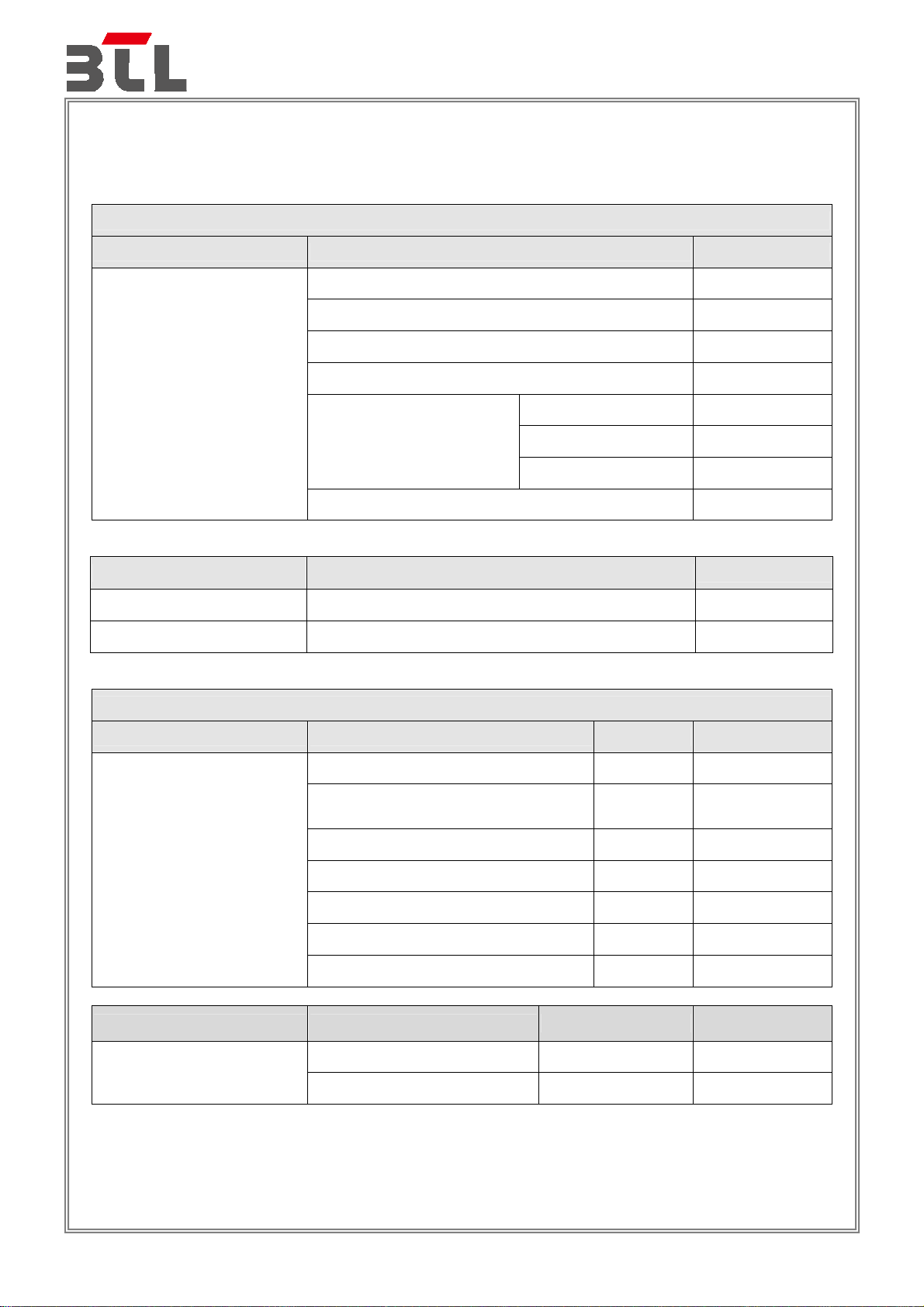
1. SUMMARY OF TEST RESULTS
Test procedures according to the technical standards:
Report No.: BTL-EMC-1-1907C038
Emission
Standard(s) Test Item
EN 55032:2015+AC:2016
Standard(s) Test Item
EN 61000-3-2:2014 Harmonic current PASS
EN 61000-3-3:2013 Voltage fluctuations (Flicker) PASS
Result
Radiated emissions up to 1 GHz PASS
Radiated emissions above 1 GHz PASS
Radiated emissions from FM receivers N/A
Conducted emissions AC mains power port PASS
AAN PASS
Asymmetric mode
conducted emissions
Current Probe N/A
CP+CVP N/A
Conducted differential voltage emissions N/A
Result
Immunity
Standard(s) Ref Standard(s)
IEC 61000-4-2:2008 ESD PASS
IEC 61000-4-3:2006+A1: 2007+A2:2010 RS PASS
IEC 61000-4-4:2012 EFT PASS
EN 55035:2017
IEC 61000-4-5:2014 +A1:2017 Surge PASS
IEC 61000-4-6:2013 CS PASS
IEC 61000-4-8:2009 PFMF PASS
IEC 61000-4-11:2004+A1:2017 Dip PASS
Standard(s) Section
4.2.7 BIN-R N/A
EN 55035:2017
4.2.7 BIN-I N/A
NOTE:
(1) “N/A” denotes test is not applicable to this device.
Test Item Result
Test Item Result
Page 7 of 105
Page 8
Report No.: BTL-EMC-1-1907C038
1.1 TEST FACILITY
The test facilities used to collect the test data in this report is at the location of No.3, Jinshagang 1st
Road, Shixia, Dalang Town, Dongguan, Guangdong, China.
1.2 MEASUREMENT UNCERTAINTY
Where relevant, the following measurement uncertainty levels have been estimated for tests performed
on the EUT as specified in CISPR 16-4-2, The BTL measurement uncertainty is less than the CISPR
16-4-2 U
The reported uncertainty of measurement y ± U, where expanded uncertainty U is based on a standard
uncertainty multiplied by a coverage factor of k=2, providing a level of confidence of approximately 95%.
A. Radiated emissions up to 1 GHz measurement:
requirement.
cispr
Test Site Method Measurement Frequency Range
30MHz ~ 200MHz V 4.44
Ant.
H / V
U,(dB)
DG-CB08
(10m)
B. Radiated emissions above 1 GHz measurement:
Test Site Method Measurement Frequency Range U,(dB)
DG-CB08
(3m)
C. Conducted emissions AC mains power port measurement:
Test Site Method Measurement Frequency Range U,(dB)
DG-C02 CISPR 150kHz ~ 30MHz 2.60
D. Asymmetric mode conducted emissions measurement:
Test Site Method Test Item U,(dB)
DG-C02 CISPR
E. Harmonic current / Voltage fluctuations (Flicker) measurement:
Test Site Method Item U (%)
CISPR
CISPR 1GHz ~ 6GHz 4.36
30MHz ~ 200MHz H 3.44
200MHz ~ 1,000MHz V 4.28
200MHz ~ 1,000MHz H 3.52
AAN Cat.3 LCL = 55 ... 40 dB 3.40
AAN Cat.5 LCL = 65 ... 50 dB 3.86
AAN Cat.6 LCL = 75 ... 60 dB 4.36
DG-C01
EN 61000-3-2 Current 0.593
EN 61000-3-3 Voltage 0.595
Page 8 of 105
Page 9
F. Immunity Measurement:
Test Site Method Item U
Report No.: BTL-EMC-1-1907C038
Rise time tr 6.80%
DG-SR02 IEC 61000-4-2
DG-CB05 IEC 61000-4-3
DG-SR05 IEC 61000-4-4
DG-SR02 IEC 61000-4-5
Peak current Ip 6.30%
Current at 30 ns 6.50%
Current at 60 ns 6.90%
Electromagnetic field immunity
test
Peak voltage (V
) 3.7%
P
2.38dB
Rise time (tr) 4.4%
Pulse width(tw) 4.1%
Pulse Freq.(kHz) 0.8%
Burst Duration(ms) 1.4%
Burst Period(ms) 1.4%
Peak voltage (VP)-with clamp 3.7%
Rise time (tr) -with clamp 5.0%
Pulse width(tw) -with clamp 4.8%
Open-Circuit Output Voltage
(1.2/50us)
3.8%
Open circuit front time (1.2/50us) 6.3%
Open circuit time of half value
(1.2/50us)
Open-Circuit Output Voltage
(10/700us)
4.6%
3.8%
Open circuit front time (10/700us) 5.9%
Open circuit time of half value
(10/700us)
4.7%
CDN 1.32dB
EM clamp 3.16dB
DG-CB06 IEC 61000-4-6
DG-SR05 IEC 61000-4-8 Magnetic Field Level
Audio breakthrough measurement
for RS 2G/3G
Audio breakthrough measurement
for RS 4G
1.42dB
1.44dB
3.787 %
DIP Amplitude 0.5%
DG-SR05 IEC 61000-4-11
DIP Time Event 3%
Note: Unless specifically mentioned, the uncertainty of measurement has not been taken into account to
declare the compliance or non-compliance to the specification.
Page 9 of 105
Page 10

1.3 TEST ENVIRONMENT CONDITIONS
Test Item Temperature Humidity Tested By
Report No.: BTL-EMC-1-1907C038
Radiated emissions
up to 1 GHz
Radiated emissions
above 1 GHz
Conducted emissions
AC mains power port
25°C 60% Promise Yin
25°C 60% Promise Yin
25°C 53% Leo Lu
Asymmetric mode conducted emissions 25°C 53% Gatsby Wang
Harmonic current 25°C 55% Bang Liang
Voltage fluctuations
(Flicker)
25°C 55% Bang Liang
Test Item Temperature Humidity Pressure Tested By
ESD 25°C 48% 1012hPa Celina Lai
RS 25°C 52% / Hunter Xu
EFT 25°C 50% / Maggie Peng
Surge 25°C 50% / Maggie Peng
CS 25°C 54% / Jason Liang
PFMF 25°C 50% / Maggie Peng
Dip 25°C 50% / Maggie Peng
Page 10 of 105
Page 11
2. GENERAL INFORMATION
2.1 GENERAL DESCRIPTION OF EUT
Equipment
Report No.: BTL-EMC-1-1907C038
AC1900 MU-MIMO Wi-Fi Router
Note:
Brand Name
Test Model
Series Model
Model Difference(s)
Power Source
Power Rating
Connecting I/O Port
Classification of EUT
Highest Internal Frequency(Fx)
1. For a more detailed features description, please refer to the manufacturer’s specifications or the user's
manual.
tp-link
Archer C80
N/A
N/A
DC Voltage supplied from AC/DC adapter.
Model: 1#T120150-2C1
2#T120100-2C1
1# I/P:100-240V~, 50/60Hz 0.6A
O/P:12V
2# I/P:100-240V~, 50/60Hz 0.3A
O/P:12V
1*DC port
4*LAN port
1*WAN port
Class B
5250MHz
1.5A
1A
Page 11 of 105
Page 12
Report No.: BTL-EMC-1-1907C038
2.2 DESCRIPTION OF TEST MODES
To investigate the maximum EMI emission characteristics generates from EUT, the test system was
pre-scanning tested base on the consideration of following EUT operation mode or test configuration mode
which possible have effect on EMI emission level. Each of these EUT operation mode(s) or test
configuration mode(s) mentioned above was evaluated respectively.
Pretest Mode Description
Mode 1 FULL SYSTEM(2.4G WIFI+5G WIFI)
Mode 2 WAN 1Gbps
Mode 3 WAN 10Mbps
Mode 4 LAN1 1Gbps
Mode 5 LAN1 10Mbps
Radiated emissions up to 1 GHz test
Final Test Mode Description
Mode 1
Radiated emissions Above 1 GHz test
Final Test Mode Description
Mode 1
Conducted emissions AC mains power port test
Final Test Mode Description
Mode 1
Asymmetric mode conducted emissions test
Final Test Mode Description
Mode 2 WAN 1Gbps
Mode 3 WAN 10Mbps
Mode 4 LAN1 1Gbps
Mode 5 LAN1 10Mbps
Harmonic current & Voltage fluctuations (Flicker) Test
FULL SYSTEM(2.4G WIFI+5G WIFI)
FULL SYSTEM(2.4G WIFI+5G WIFI)
FULL SYSTEM(2.4G WIFI+5G WIFI)
Final Test Mode Description
Mode 1
FULL SYSTEM(2.4G WIFI+5G WIFI)
Page 12 of 105
Page 13

Report No.: BTL-EMC-1-1907C038
For Immunity Test
Final Test Mode Description
Note:
Mode 1
1. The product support WIFI function.
The frequency of WIFI exemption is 2400-2483.5MHz, 5150-5250MHz.
2. Radiated emission above 1GHz tested with 2.4G&5G filter.
FULL SYSTEM(2.4G WIFI+5G WIFI)
Page 13 of 105
Page 14
Report No.: BTL-EMC-1-1907C038
2.3 EUT OPERATING CONDITIONS
The EUT exercise program used during radiated and/or conducted emission measurement was designed to
exercise the various system components in a manner similar to a typical use. The standard test signals and
output signal as following:
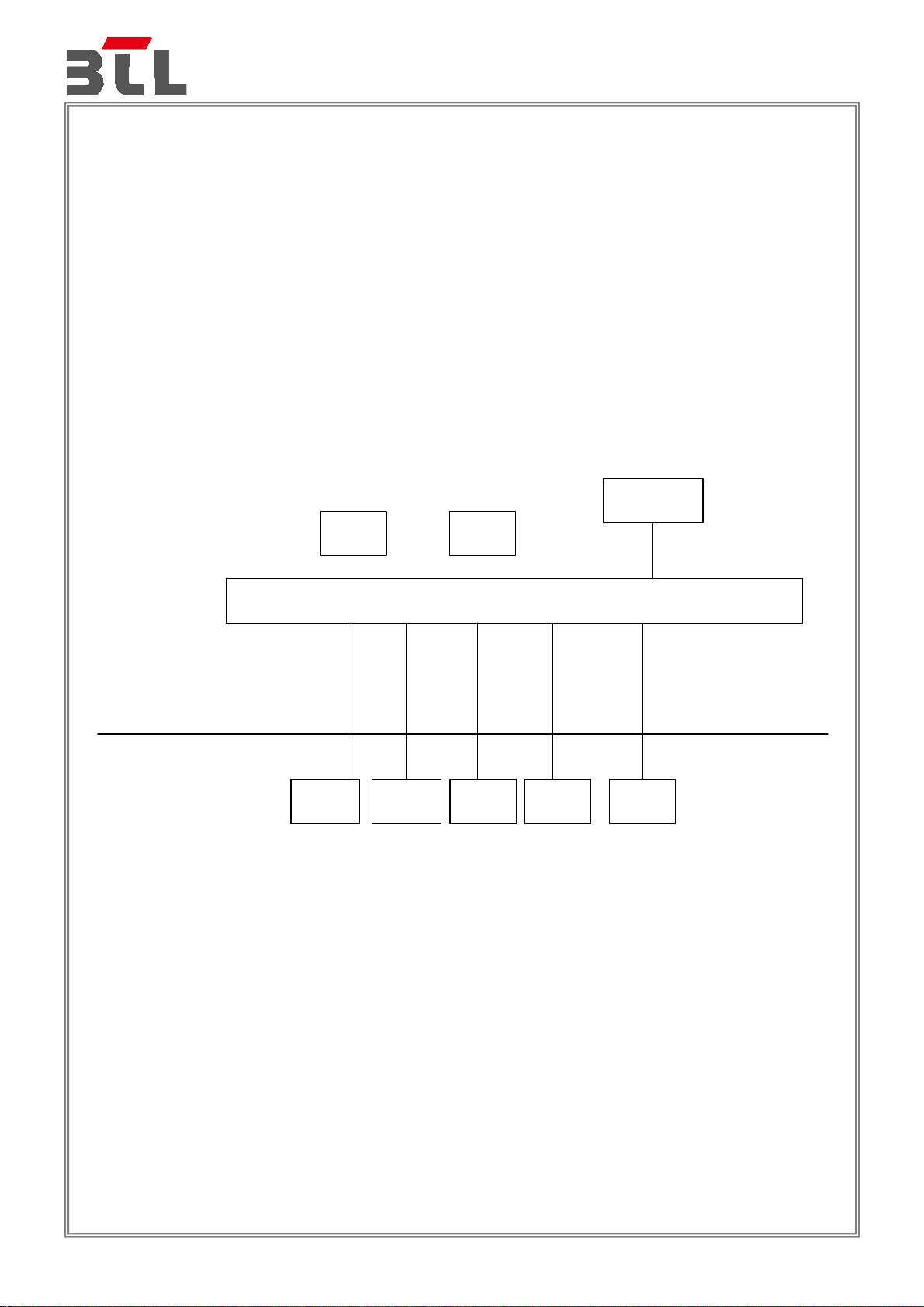
1. EUT connected to Adapter via DC cable.
2. EUT connected to Notebook (A&B&C&D&G) via RJ45 cable.
3. EUT connected to Notebook (E&F) via 2.4G&5G WIFI.
2.4 BLOCK DIAGRAM SHOWING THE CONFIGURATION OF SYSTEM TESTED
AC 100-240V
Ground Plane
Remote System
2.4G WIFI 5G WIFI
(E)
Notebook
(A)
Notebook
1
Notebook
2
(B)
(F)
Notebook
(C)
Notebook
EUT
3
(D)
Notebook
4
EUT
( Adapter)
6
5
(G)
Notebook
Page 14 of 105
Page 15
Report No.: BTL-EMC-1-1907C038
2.5 DESCRIPTION OF SUPPORT UNITS
The EUT has been tested as an independent unit together with other necessary accessories or support
units. The following support units or accessories were used to form a representative test configuration
during the tests.
Item Equipment Mfr/Brand Model/Type No. Series No.
A
B
C
D
E Notebook Lenovo V310-14ISK LR07GZHC
F Notebook Lenovo V310-14ISK LR07GZML
G Notebook Lenovo E445 MP-05Y56S
Item Cable Type Shielded Type Ferrite Core Length
1 RJ45 Cable
2 RJ45 Cable
3 RJ45 Cable NO NO 10m
4 RJ45 Cable
5 RJ45 Cable
6 DC Cable NO NO 1.5m
Notebook Lenovo G40 YB09261386
Notebook DELL VOSTRO 14-3459 27072218306
Notebook Lenovo E445 MP-05Y3X6
Notebook Lenovo Y510P YB04604082
NO NO 10m
NO NO 10m
NO NO 10m
NO NO 10m
Page 15 of 105
Page 16

3. EMC EMISSION TEST
3.1 RADIATED EMISSIONS UP TO 1 GHZ
3.1.1 LIMITS
Class B equipment up to 1 GHz
Report No.: BTL-EMC-1-1907C038
Frequency
Range
MHz
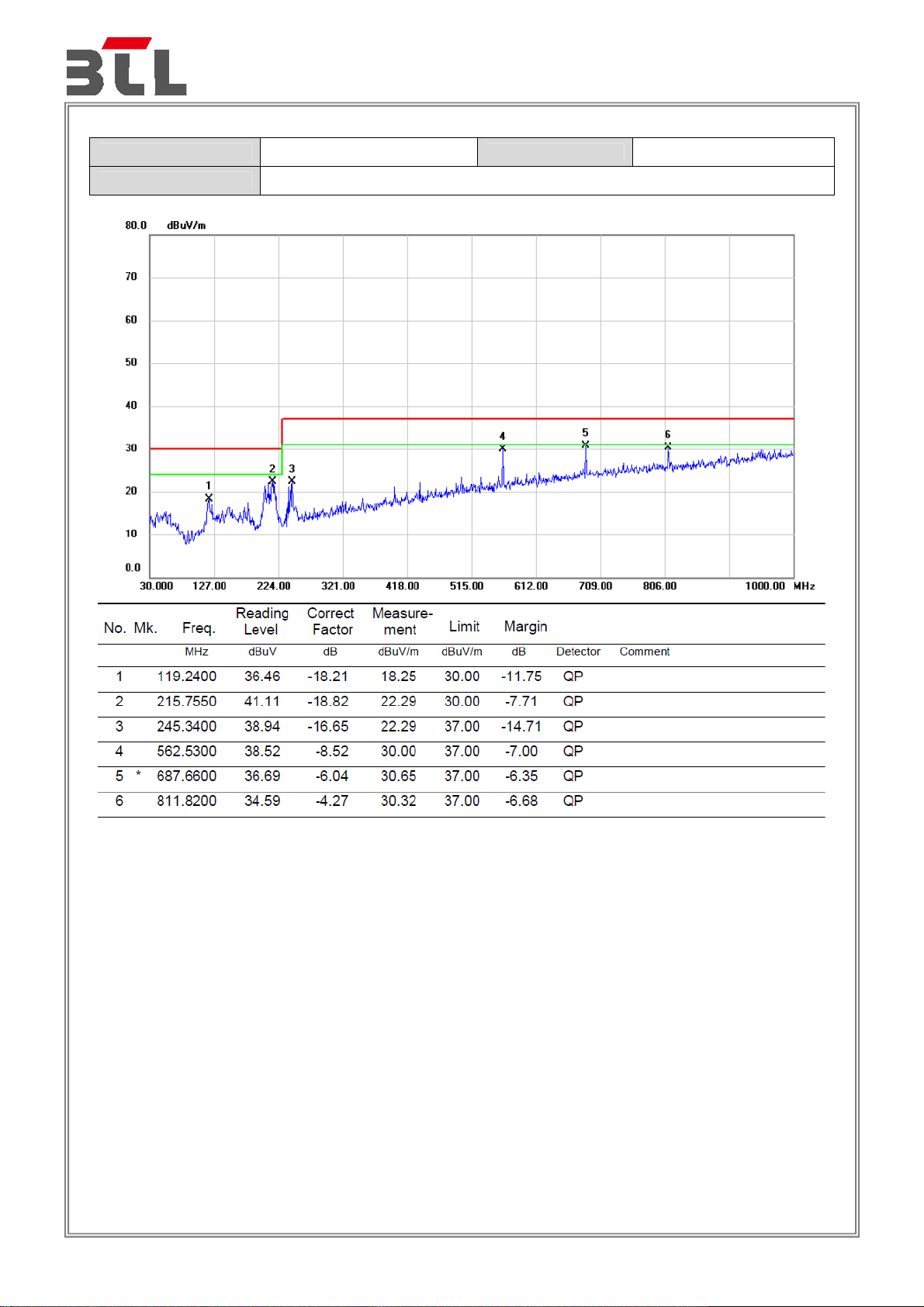
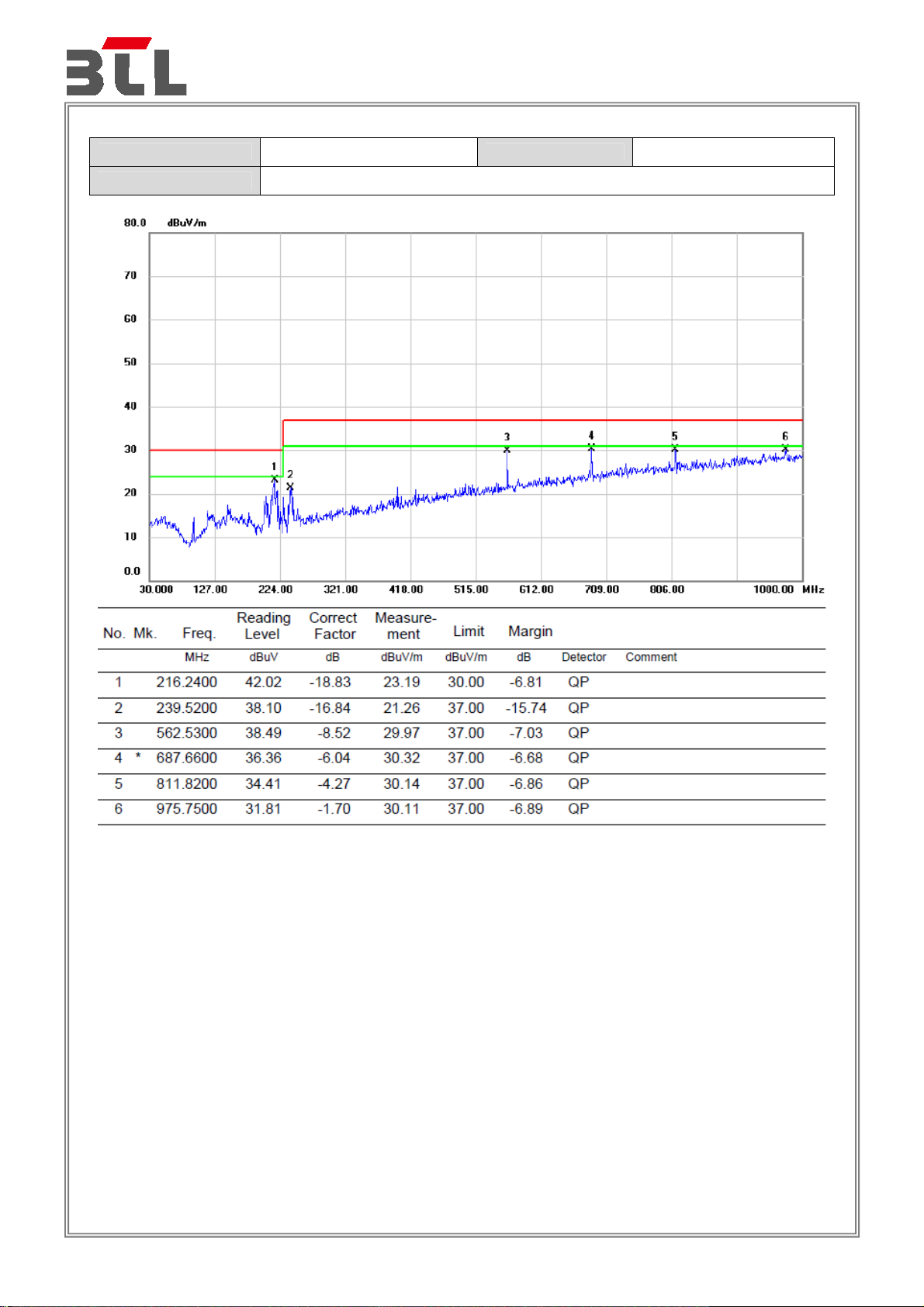
30 - 230
Notes:
(1) The limit for radiated test was performed according to as following: EN 55032
(2) The tighter limit applies at the band edges.
(3) Emission level (dBuV/m)=20log Emission level (uV/m).
(4) The test result calculated as following:
230 - 1000 37
Measurement Value = Reading Level + Correct Factor
Correct Factor = Antenna Factor + Cable Loss - Amplifier Gain(if use)
Margin Level = Measurement Value - Limit Value
Facility
SAC 10
Measurement
Distance
m
Detector type/
bandwidth
Quasi peak / 120
kHz
Class B limits
dB(μV/m)
30
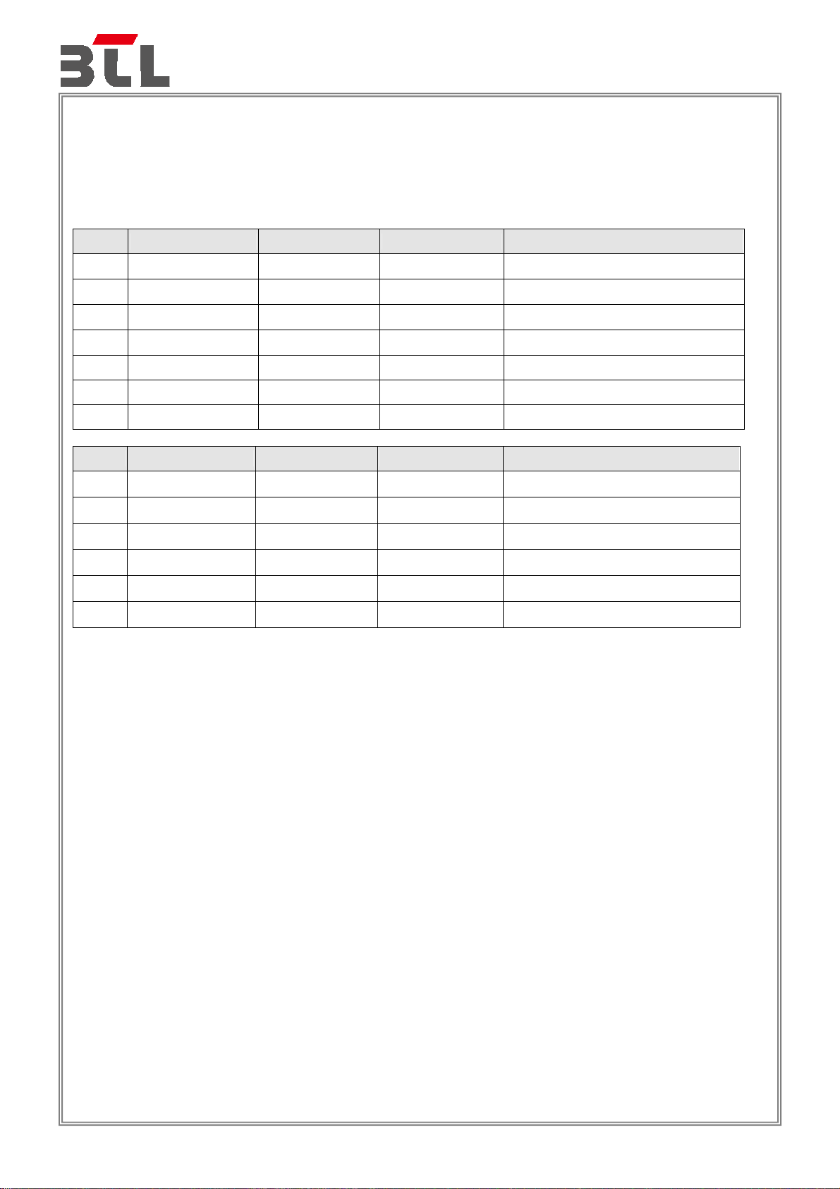
3.1.2 MEASUREMENT INSTRUMENTS LIST
Item Kind of Equipment Manufacturer Type No. Serial No. Calibrated until
1 Receiver Keysight N9038A MY54450004 Aug. 03, 2020
2 MXE EMI Receiver Agilent N9038A MY53220133 Mar. 10, 2020
3 Pre-Amplifier
4 Pre-Amplifier
5
6
7 Cable emci
8 Cable emci
9
10
11 Attenuator EMCI EMCI-N-6-06 N0670 Dec. 02, 2020
12 Attenuator EMCI EMCI-N-6-06 N0671 Oct. 26, 2020
Remark: “N/A” denotes no model name, no serial no. or no calibration specified.
Trilog-Broadband
Antenna
Trilog-Broadband
Antenna
Measurement
Software
Multi-Device
Controller
All calibration period of equipment list is one year.
EMC
INSTRUMENT
EMC
INSTRUMENT
Schwarzbeck VULB9168 946 Oct. 26, 2020
Schwarzbeck VULB9168 947 Dec. 02, 2020
Farad
ETS-Lindgren 2090 N/A N/A
EMC 9135 980284 Mar. 10, 2020
EMC 9135 980283 Mar. 10, 2020
LMR-400(5m+
11m+ 15m)
LMR-400(5m+
8m+8m)
EZ-EMC
Ver.BTL-2ANT-
1
N/A Nov. 22, 2020
N/A Nov. 22, 2020
N/A N/A
Page 16 of 105
Page 17

Report No.: BTL-EMC-1-1907C038
3.1.3 TEST PROCEDURE
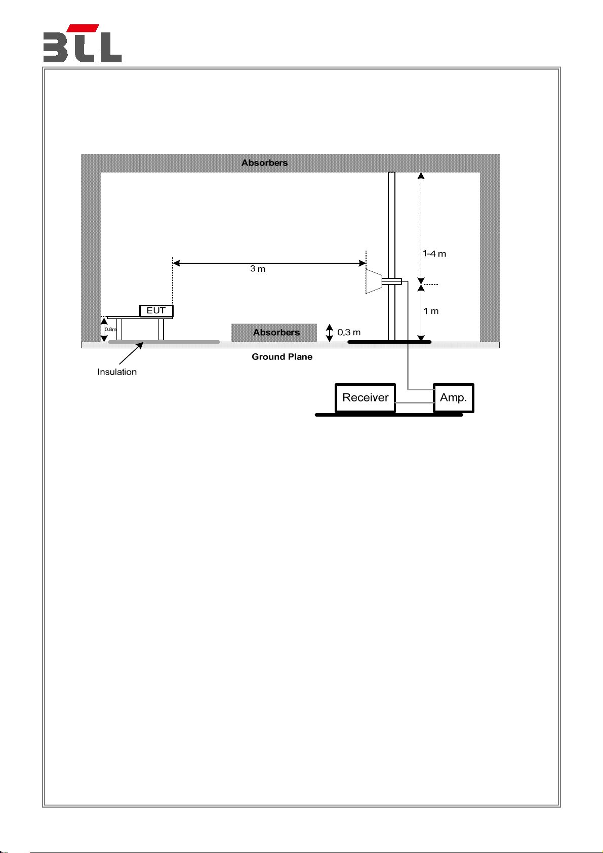
a. The measuring distance of 10 m shall be used for measurements. The EUT was placed on the top of a
rotating table 0.8 meter above the ground at a 10 meter semi-anechoic chamber. The table was rotated
360 degrees to determine the position of the highest radiation.
b. The height of the equipment or of the substitution antenna shall be 0.8 m, the height of the test antenna
shall vary between 1 m to 4 m. Both horizontal and vertical polarizations of the antenna are set to make
the measurement.
c. The initial step in collecting radiated emission data is a receiver peak detector mode pre-scanning the
measurement frequency range. Significant peaks are then marked and then Quasi Peak detector mode
re-measured.
d. All readings are Peak unless otherwise stated QP in column of Note. Peak denotes that the Peak reading
compliance with the QP Limits and then QP Mode measurement didn‘t perform.
e. For the actual test configuration, please refer to the related Item - Block Diagram of system tested.
3.1.4 DEVIATION FROM TEST STANDARD
No deviation
3.1.5 TEST SETUP
UP TO 1 GHZ
Page 17 of 105
Page 18
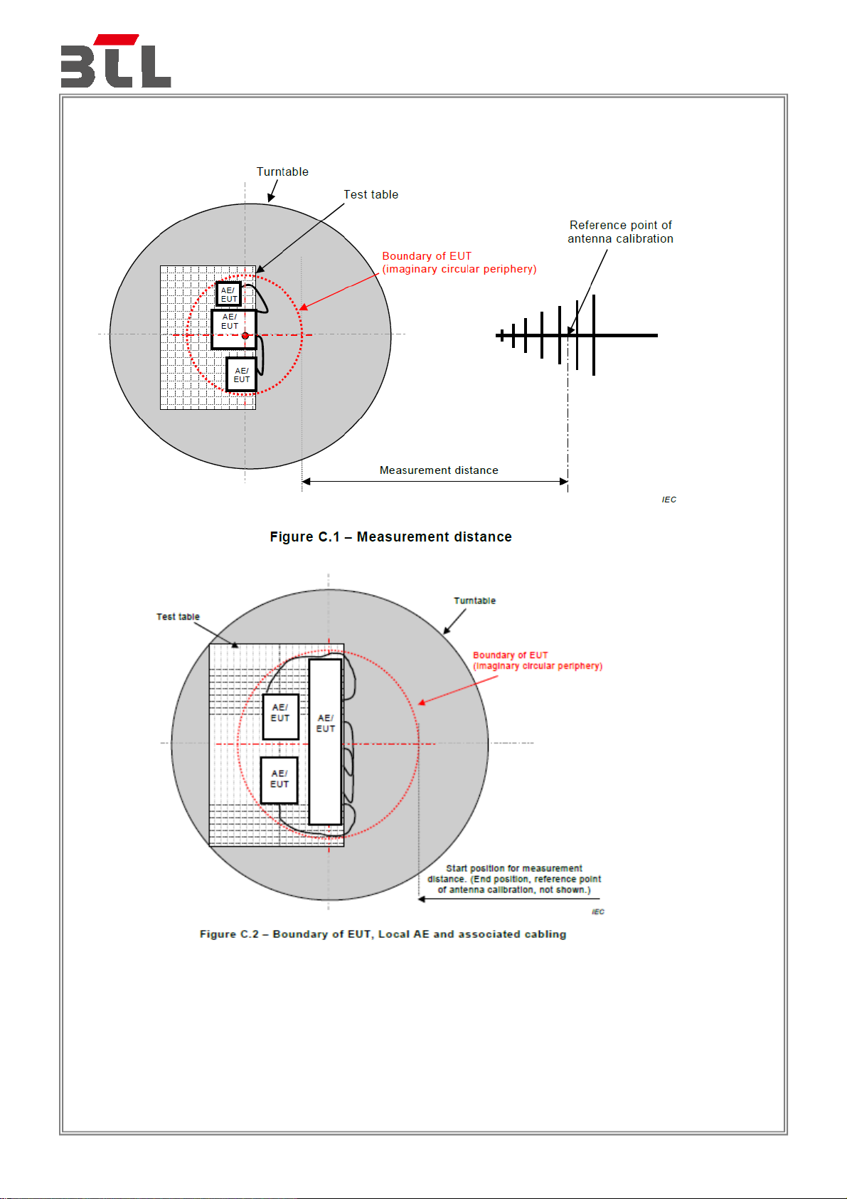
3.1.6 MEASUREMENT DISTANCE
Report No.: BTL-EMC-1-1907C038
Page 18 of 105
Page 19
Report No.: BTL-EMC-1-1907C038
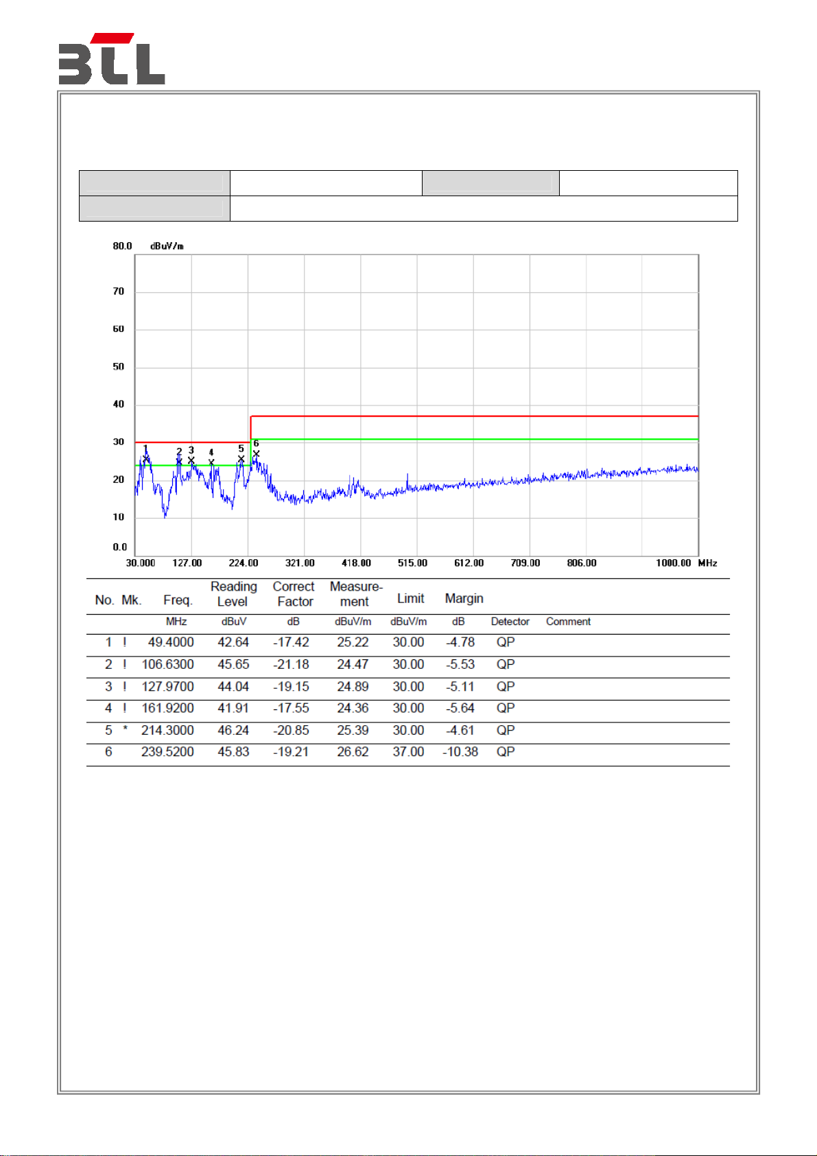
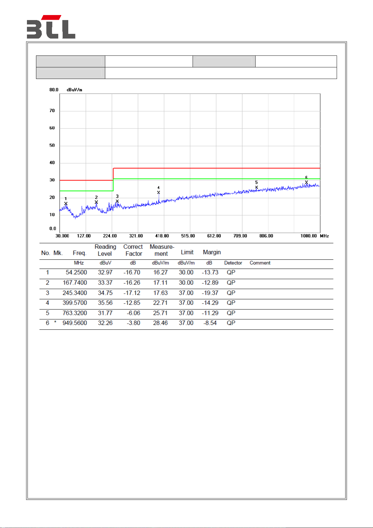
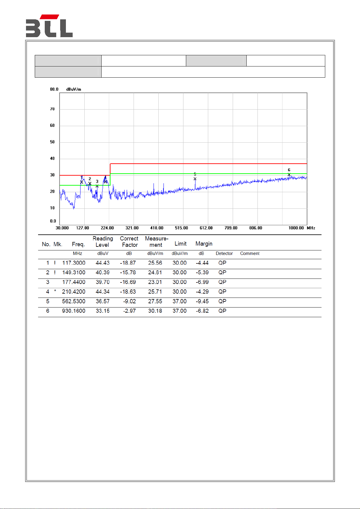
3.1.7 TEST RESULTS
Test Voltage AC 230V/50Hz Polarization Vertical
Test Mode Mode 1_Adapter( Model: T120150-2C1)
Page 19 of 105
Page 20
Report No.: BTL-EMC-1-1907C038
Test Voltage AC 230V/50Hz Polarization Horizontal
Test Mode Mode 1_Adapter( Model: T120150-2C1)
Page 20 of 105
Page 21

Report No.: BTL-EMC-1-1907C038
Test Voltage AC 110V/60Hz Polarization Vertical
Test Mode Mode 1_Adapter( Model: T120150-2C1)
Page 21 of 105
Page 22

Report No.: BTL-EMC-1-1907C038
Test Voltage AC 110V/60Hz Polarization Horizontal
Test Mode Mode 1_Adapter( Model: T120150-2C1)
Page 22 of 105
Page 23
Report No.: BTL-EMC-1-1907C038
Test Voltage AC 230V/50Hz Polarization Vertical
Test Mode Mode 1_Adapter( Model: T120100-2C1)
Page 23 of 105
Page 24
Report No.: BTL-EMC-1-1907C038
Test Voltage AC 230V/50Hz Polarization Horizontal
Test Mode Mode 1_Adapter( Model: T120100-2C1)
Page 24 of 105
Page 25

Report No.: BTL-EMC-1-1907C038
Test Voltage AC 110V/60Hz Polarization Vertical
Test Mode Mode 1_Adapter( Model: T120100-2C1)
Page 25 of 105
Page 26
Report No.: BTL-EMC-1-1907C038
Test Voltage AC 110V/60Hz Polarization Horizontal
Test Mode Mode 1_Adapter( Model: T120100-2C1)
Page 26 of 105
Page 27
3.2 RADIATED EMISSIONS ABOVE 1 GHZ
3.2.1 LIMITS
Class B equipment above 1 GHz
Report No.: BTL-EMC-1-1907C038
Frequency
Range
MHz
1000 - 3000
3000 - 6000 54
1000 - 3000
3000 - 6000 74
Notes:
(1) The limit for radiated test was performed according to as following: EN 55032
(2) The tighter limit applies at the band edges.
(3) Emission level (dBuV/m)=20log Emission level (uV/m).
(4) The test result calculated as following:
Measurement Value = Reading Level + Correct Factor
Correct Factor = Antenna Factor + Cable Loss - Amplifier Gain(if use)
Margin Level = Measurement Value - Limit Value
Required highest frequency for radiated measurement
Highest internal frequency
Fx ≦108 MHz
108<Fx ≦500 MHz
500< Fx ≦1000 MHz
Fx >1 GHz
Facility
FSOATS 3
(Fx)
Measurement
Distance
m
Class B limits
Detector
type/bandwidth
Average /
1 MHz
Peak /
1 MHz
Highest measured frequency
1 GHz
2 GHz
5 GHz
5 x F
up to a maximum of 6 GHz
x
dB(μV/m)
50
70
Page 27 of 105
Page 28

Report No.: BTL-EMC-1-1907C038
3.2.2 MEASUREMENT INSTRUMENTS LIST
Item Kind of Equipment Manufacturer Type No. Serial No. Calibrated until
1 Horn Antenna EMCO 3115 9605-4803 Mar. 23, 2020
2 Amplifier Agilent 8449B 3008A02584 Aug. 03, 2020
3 MXE EMI Receiver Agilent N9038A MY53220133 Mar. 10, 2020
4
5
6 Controller MF MF-7802 MF780208159 N/A
7 Cable MIcable Inc. B10-01-01-5M 18047123 Mar. 01, 2020
8 Cable MIcable Inc. B10-01-01-10M 18072746 Mar. 01, 2020
9 Cable N/A
10 Band Reject Filter
11 Band Rject filter Micro-Tronics BRC50705-01 10 Mar. 10, 2020
Remark: “N/A” denotes no model name, no serial no. or no calibration specified.
Measurement
Software
Multi-Device
Controller
All calibration period of equipment list is one year.
Farad
ETS-Lindgren 2090 N/A N/A
Wairrwright
Instruments
Gmbh
EZ-EMC
Ver.BTL-2ANT-1
A50-3.5M3.5M-1
.5M-AT
WRCG
2400/2483-2375
/2505-50/10SS
N/A N/A
18041824 Mar. 01, 2020
16 Mar. 10, 2020
3.2.3 TEST PROCEDURE
a. The measuring distance of 3 m shall be used for measurements. The EUT was placed on the top of a
rotating table 0.8 meter above the ground at a 10 meter semi-anechoic chamber. The table was rotated
360 degrees to determine the position of the highest radiation.
b. The height of the equipment or of the substitution antenna shall be 0.8 m, the height of the test antenna
shall vary between 1 m to 4 m. Both horizontal and vertical polarizations of the antenna are set to make
the measurement.
c. The initial step in collecting radiated emission data is a receiver peak detector mode pre-scanning the
measurement frequency range. Significant peaks are then marked and then Quasi Peak detector mode
re-measured.
d. All readings are Peak Mode value unless otherwise stated AVG in column of Note. If the Peak Mode
Measured value compliance with the Peak Limits and lower than AVG Limits, the EUT shall be deemed to
meet both Peak & AVG Limits and then only Peak Mode was measured, but AVG Mode didn‘t perform.
e. For the actual test configuration, please refer to the related Item - Block Diagram of system tested.
3.2.4 DEVIATION FROM TEST STANDARD
No deviation
Page 28 of 105
Page 29
3.2.5 TEST SETUP
Report No.: BTL-EMC-1-1907C038
ABOVE 1 GHZ
Page 29 of 105
Page 30

3.2.6 MEASUREMENT DISTANCE
Report No.: BTL-EMC-1-1907C038
Page 30 of 105
Page 31

Report No.: BTL-EMC-1-1907C038
3.2.7 TEST RESULTS
Test Voltage AC 230V/50Hz Polarization Vertical
Test Mode Mode 1_Adapter( Model: T120150-2C1)
Page 31 of 105
Page 32

Report No.: BTL-EMC-1-1907C038
Test Voltage AC 230V/50Hz Polarization Horizontal
Test Mode Mode 1_Adapter( Model: T120150-2C1)
Page 32 of 105
Page 33

Report No.: BTL-EMC-1-1907C038
Test Voltage AC 110V/60Hz Polarization Vertical
Test Mode Mode 1_Adapter( Model: T120150-2C1)
Page 33 of 105
Page 34

Report No.: BTL-EMC-1-1907C038
Test Voltage AC 110V/60Hz Polarization Horizontal
Test Mode Mode 1_Adapter( Model: T120150-2C1)
Page 34 of 105
Page 35

Report No.: BTL-EMC-1-1907C038
Test Voltage AC 230V/50Hz Polarization Vertical
Test Mode Mode 1_Adapter( Model: T120100-2C1)
Page 35 of 105
Page 36

Report No.: BTL-EMC-1-1907C038
Test Voltage AC 230V/50Hz Polarization Horizontal
Test Mode Mode 1_Adapter( Model: T120100-2C1)
Page 36 of 105
Page 37

Report No.: BTL-EMC-1-1907C038
Test Voltage AC 110V/60Hz Polarization Vertical
Test Mode Mode 1_Adapter( Model: T120100-2C1)
Page 37 of 105
Page 38

Report No.: BTL-EMC-1-1907C038
Test Voltage AC 110V/60Hz Polarization Horizontal
Test Mode Mode 1_Adapter( Model: T120100-2C1)
Page 38 of 105
Page 39

Report No.: BTL-EMC-1-1907C038
3.3 CONDUCTED EMISSION MEASUREMENT AT AC MAINS POWER PORTS
3.3.1 LIMITS
Requirements for conducted emissions from AC mains power ports of Class B equipment
Frequency Range
Coupling
Detector Type /
Class B Limits
MHz
0.15 - 0.5
0.5 - 5 56
Device
AMN
bandwidth
Quasi Peak / 9
kHz
(dB(μV) )
66-56
5 - 30 60
0.15 - 0.5
0.5 - 5 46
5 - 30 50
AMN
Average /
9 kHz
56-46
NOTE:
(1) The test result calculated as following:
Measurement Value = Reading Level + Correct Factor
Correct Factor = Insertion Loss + Cable Loss + Attenuator Factor(if use)
Margin Level = Measurement Value – Limit Value
3.3.2 MEASUREMENT INSTRUMENTS LIST
Item Kind of Equipment Manufacturer Type No. Serial No. Calibrated until
1 EMI Test Receiver R&S ESCI 100382 Mar. 10, 2020
2 LISN EMCO 3816/2 52765 Mar. 10, 2020
3
TWO-LINE
V-NETWORK
4 50Ω Terminator SHX TF5-3 15041305 Mar. 10, 2020
5
Measurement
Software
6 Cable N/A RG223 12m Mar. 12, 2020
Remark: “N/A” denotes no model name, no serial no. or no calibration specified.
Except * item, all calibration period of equipment list is one year.
R&S ENV216 101447 May. 19, 2020
Farad
EZ-EMC
Ver.NB-03A1-01
N/A N/A
Page 39 of 105
Page 40

Report No.: BTL-EMC-1-1907C038
3.3.3 TEST PROCEDURE
The EUT was placed 0.8 meters from the horizontal ground plane with EUT being connected to the
a.
power mains through a line impedance stabilization network (LISN). All other support equipment
powered from additional LISN(s). The LISN provide 50 Ohm/ 50uH of coupling impedance for the
measuring instrument.
b.
Interconnecting cables that hang closer than 40 cm to the ground plane shall be folded back
and forth in the center forming a bundle 30 to 40 cm long.
c.
I/O cables that are not connected to a peripheral shall be bundled in the center. The end of the
cable may be terminated, if required, using the correct terminating impedance. The overall
length shall not exceed 1 m.
d.
LISN at least 80 cm from nearest part of EUT chassis.
For the actual test configuration, please refer to the related Item –EUT Test Photos.
e.
3.3.4 DEVIATION FROM TEST STANDARD
No deviation
3.3.5 TEST SETUP
Vertical Reference Ground Plane
40 cm
EUT Test Receiver
Insulation
LISN
80 cm
Horizontal Reference Ground Plane
Page 40 of 105
Page 41

Report No.: BTL-EMC-1-1907C038
3.3.6 TEST RESULTS
Test Voltage AC 230V/50Hz Phase Line
Test Mode Mode 1_Adapter( Model: T120150-2C1)
Page 41 of 105
Page 42

Report No.: BTL-EMC-1-1907C038
Test Voltage AC 230V/50Hz Phase Neutral
Test Mode Mode 1_Adapter( Model: T120150-2C1)
Page 42 of 105
Page 43

Report No.: BTL-EMC-1-1907C038
Test Voltage AC 110V/60Hz Phase Line
Test Mode Mode 1_Adapter( Model: T120150-2C1)
Page 43 of 105
Page 44

Report No.: BTL-EMC-1-1907C038
Test Voltage AC 110V/60Hz Phase Neutral
Test Mode Mode 1_Adapter( Model: T120150-2C1)
Page 44 of 105
Page 45

Report No.: BTL-EMC-1-1907C038
Test Voltage AC 230V/50Hz Phase Line
Test Mode Mode 1_Adapter( Model: T120100-2C1)
Page 45 of 105
Page 46

Report No.: BTL-EMC-1-1907C038
Test Voltage AC 230V/50Hz Phase Neutral
Test Mode Mode 1_Adapter( Model: T120100-2C1)
Page 46 of 105
Page 47

Report No.: BTL-EMC-1-1907C038
Test Voltage AC 110V/60Hz Phase Line
Test Mode Mode 1_Adapter( Model: T120100-2C1)
Page 47 of 105
Page 48

Report No.: BTL-EMC-1-1907C038
Test Voltage AC 110V/60Hz Phase Neutral
Test Mode Mode 1_Adapter( Model: T120100-2C1)
Page 48 of 105
Page 49

Report No.: BTL-EMC-1-1907C038
3.4 ASYMMETRIC MODE CONDUCTED EMISSIONS TEST
3.4.1 LIMITS
Requirements for asymmetric mode conducted emissions from Class B equipment
Frequency
Range
Coupling device
MHz
0.15 - 0.5
0.5 - 30 74
0.15 - 0.5
0.5 - 30 64
AAN
AAN
Detector type
/ Bandwidth
Quasi Peak /
9 kHz
Average /
9 kHz
Class B
voltage limits
dB(μV)
84 - 74
74 - 64
Class B
current limits
dB(μA)
n/a
NOTE:
(1) The test result calculated as following:
Measurement Value = Reading Level + Correct Factor
Correct Factor = Insertion Loss + Cable Loss + Attenuator Factor(if use)
Margin Level = Measurement Value – Limit Value
3.4.2 MEASUREMENT INSTRUMENTS LIST
Item Kind of Equipment Manufacturer Type No. Serial No. Calibrated until
1 EMI Test Receiver R&S ESCI 100382 Mar. 10, 2020
2 LISN EMCO 3816/2 52765 Mar. 10, 2020
3
4 50Ω Terminator SHX TF5-3 15041305 Mar. 10, 2020
5
6 Cable N/A RG223 12m Mar. 12, 2020
TWO-LINE
V-NETWORK
Measurement
Software
R&S ENV216 101447 May. 19, 2020
Farad
EZ-EMC
Ver.NB-03A1-01
N/A N/A
7 ISN TESEQ ISN T800 42838 Aug. 03, 2020
Remark: “N/A” denotes no model name, no serial No. or no calibration specified.
Except * item, all calibration period of equipment list is one year.
Page 49 of 105
Page 50

Report No.: BTL-EMC-1-1907C038
3.4.3 TEST PROCEDURE
The EUT was placed 0.8 meters from the horizontal ground plane with EUT being connected to the
a.
power mains through a line impedance stabilization network (LISN). All other support equipment
powered from additional LISN(s). The LISN provide 50 Ohm/ 50uH of coupling impedance for the
measuring instrument.
Interconnecting cables that hang closer than 40 cm to the ground plane shall be folded back
b.
and forth in the center forming a bundle 30 to 40 cm long.
I/O cables that are not connected to a peripheral shall be bundled in the center. The end of the
c.
cable may be terminated, if required, using the correct terminating impedance. The overall
length shall not exceed 1 m.
For the actual test configuration, please refer to the related Item –EUT Test Photos.
d.
AAN at least 80 cm from nearest part of EUT chassis.
e.
NOTE:
The communication function of EUT was executed and AAN was connected between EUT and
1.
associated equipment and the AAN was connected directly to reference ground plane.
Measure the voltage at the measurement port of the AAN
Correct the measured voltage by adding the AAN voltage division factor
Compare the corrected voltage with the limit.
3.4.4 DEVIATION FROM TEST STANDARD
No deviation
3.4.5 TEST SETUP
a) Cable Type: Balanced Unscreened, Screened or Coaxial
Page 50 of 105
Page 51

3.4.6 TEST RESULTS
Test Voltage AC 230V/50Hz
Test Mode Mode 2_Adapter( Model: T120150-2C1)
Report No.: BTL-EMC-1-1907C038
Page 51 of 105
Page 52

Test Voltage AC 230V/50Hz
Test Mode Mode 3_Adapter( Model: T120150-2C1)
Report No.: BTL-EMC-1-1907C038
Page 52 of 105
Page 53

Test Voltage AC 230V/50Hz
Test Mode Mode 4_Adapter( Model: T120150-2C1)
Report No.: BTL-EMC-1-1907C038
Page 53 of 105
Page 54

Test Voltage AC 230V/50Hz
Test Mode Mode 5_Adapter( Model: T120150-2C1)
Report No.: BTL-EMC-1-1907C038
Page 54 of 105
Page 55

Test Voltage AC 230V/50Hz
Test Mode Mode 2_Adapter( Model: T120100-2C1)
Report No.: BTL-EMC-1-1907C038
Page 55 of 105
Page 56

Test Voltage AC 230V/50Hz
Test Mode Mode 3_Adapter( Model: T120100-2C1)
Report No.: BTL-EMC-1-1907C038
Page 56 of 105
Page 57

Test Voltage AC 230V/50Hz
Test Mode Mode 4_Adapter( Model: T120100-2C1)
Report No.: BTL-EMC-1-1907C038
Page 57 of 105
Page 58

Test Voltage AC 230V/50Hz
Test Mode Mode 5_Adapter( Model: T120100-2C1)
Report No.: BTL-EMC-1-1907C038
Page 58 of 105
Page 59

Report No.: BTL-EMC-1-1907C038
3.5 HARMONIC CURRENT EMISSIONS TEST
3.5.1 LIMITS
The power consumption is less than 75W, there is no limit applied.
3.5.2 MEASUREMENT INSTRUMENTS LIST
Item Kind of Equipment Manufacturer Type No. Serial No. Calibrated until
1
2
3
Remark: “N/A” denotes no model name, no serial No. or no calibration specified.
Harmonics and
Flicker Analyzer
3KVA AC Power
source
Measurement
Software
All calibration period of equipment list is one year.
California
Instruments
California
Instruments
California CTS4.0 Version 4.21 N/A N/A
PACS-1 72344 Aug. 03, 2020
3001ix 56309 Aug. 03, 2020
3.5.3 TEST PROCEDURE
a. The EUT was placed on the top of a wooden table 0.8 meters above the ground and operated to
produce the maximum harmonic components under normal operating conditions.
b. The classification of EUT is according to of EN 61000-3-2. The EUT is classified as Class A:
c. The correspondent test program of test instrument to measure the current harmonics emanated from
EUT is chosen. The measure time shall be not less than the time necessary for the EUT to be
exercised.
3.5.4 DEVIATION FROM TEST STANDARD
No deviation
3.5.5 TEST SETUP
Page 59 of 105
Page 60

3.5.6 TEST RESULTS
Harmonics – Class-A
Test Voltage AC 230V/50Hz
Test Mode Mode 1_Adapter( Model: T120150-2C1)
Report No.: BTL-EMC-1-1907C038
Page 60 of 105
Page 61

Current Test Result Summary (Run time)
Test Voltage AC 230V/50Hz
Test Mode Mode 1_Adapter( Model: T120150-2C1)
Report No.: BTL-EMC-1-1907C038
Page 61 of 105
Page 62

Voltage Source Verification Data (Run time)
Test Voltage AC 230V/50Hz
Test Mode Mode 1_Adapter( Model: T120150-2C1)
Report No.: BTL-EMC-1-1907C038
Page 62 of 105
Page 63

Harmonics – Class-A
Test Voltage AC 230V/50Hz
Test Mode Mode 1_Adapter( Model: T120100-2C1)
Report No.: BTL-EMC-1-1907C038
Page 63 of 105
Page 64

Current Test Result Summary (Run time)
Test Voltage AC 230V/50Hz
Test Mode Mode 1_Adapter( Model: T120100-2C1)
Report No.: BTL-EMC-1-1907C038
Page 64 of 105
Page 65

Voltage Source Verification Data (Run time)
Test Voltage AC 230V/50Hz
Test Mode Mode 1_Adapter( Model: T120100-2C1)
Report No.: BTL-EMC-1-1907C038
Page 65 of 105
Page 66

Report No.: BTL-EMC-1-1907C038
3.6 VOLTAGE FLUCTUATIONS (FLICKER) TEST
3.6.1 LIMITS
Tes ts
Pst 1.0, Tp= 10 min. Short Term Flicker Indicator
Plt 0.65, Tp=2 hr. Long Term Flicker Indicator
dc 3.3% Relative Steady-State V-Chang
dmax 4% Maximum Relative V-change
d (t) 500 ms Relative V-change characteristic
Limits
EN 61000-3-3
Descriptions
3.6.2 MEASUREMENT INSTRUMENTS LIST
Item Kind of Equipment Manufacturer Type No. Serial No. Calibrated until
1
2
3
Remark: “N/A” denotes no model name, no serial No. or no calibration specified.
Harmonics and
Flicker Analyzer
3KVA AC Power
source
Measurement
Software
All calibration period of equipment list is one year.
California
Instruments
California
Instruments
California CTS4.0 Version 4.21 N/A N/A
PACS-1 72344 Aug. 03, 2020
3001ix 56309 Aug. 03, 2020
3.6.3 TEST PROCEDURE
a. Tests was performed according to the Test Conditions/Assessment of Voltage Fluctuations specified in
EN 61000-3-3 depend on which standard adopted for compliance measurement.
b. All types of harmonic current and/or voltage fluctuation in this report are assessed by direct
measurement using flicker-meter.
3.6.4 DEVIATION FROM TEST STANDARD
No deviation
Page 66 of 105
Page 67

3.6.5 TEST SETUP
Report No.: BTL-EMC-1-1907C038
Page 67 of 105
Page 68

3.6.6 TEST RESULTS
Test Voltage AC 230V/50Hz
Test Mode Mode 1_Adapter( Model: T120150-2C1)
Report No.: BTL-EMC-1-1907C038
Page 68 of 105
Page 69

Test Voltage AC 230V/50Hz
Test Mode Mode 1_Adapter( Model: T120100-2C1)
Report No.: BTL-EMC-1-1907C038
Page 69 of 105
Page 70

4. EMC IMMUNITY TEST
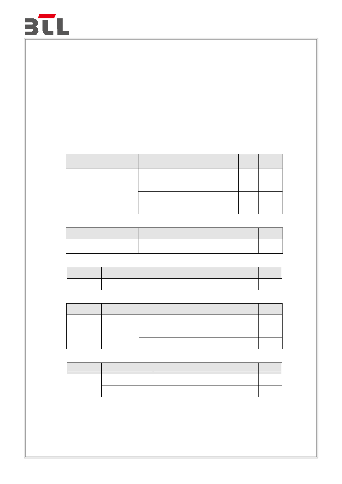
4.1 STANDARD COMPLIANCE/SEVERITY LEVEL/CRITERIA
Tests Standard No.
Electrostatic discharge
IEC 61000-4-2
(ESD)
Continuous RF electromagnetic
field disturbances,swept test
IEC 61000-4-3
(RS)
Continuous RF electromagnetic
field disturbances,spot test
IEC 61000-4-3
(RS)
Electrical fast transient/burst
immunity
IEC 61000-4-4
(EFT)
Test Specification Level /
Test Mode
±8kV air discharge
±4kV contact discharge
(Direct Mode)
±4kV HCP discharge
±4kV VCP discharge
(Indirect Mode)
80 MHz to 1000 MHz
3V/m(unmodulated, r.m.s),
1 kHz, 80%,
AM modulated
1800 MHz, 2600MHz,
3500 MHz, 5000MHz(±1 %)
3V/m(unmodulated, r.m.s),
1 kHz, 80%,
AM modulated
±0.5kV(peak)
5/50ns Tr/Th
5kHz Repetition Frequency
(100kHz Repetition Frequency for
xDSL port)
±0.5kV(peak)
5/50ns Tr/Th
5kHz Repetition Frequency
Report No.: BTL-EMC-1-1907C038
Tes t P o r t s Criteria
Enclosure B
Enclosure B
Enclosure A
Enclosure A
Analogue/digital data ports
(NOTE 2)
DC network power ports
(NOTE 2)
B
B
±1 kV(peak)
5/50ns Tr/Th
5kHz Repetition Frequency
AC mains power ports B
Page 70 of 105
Page 71

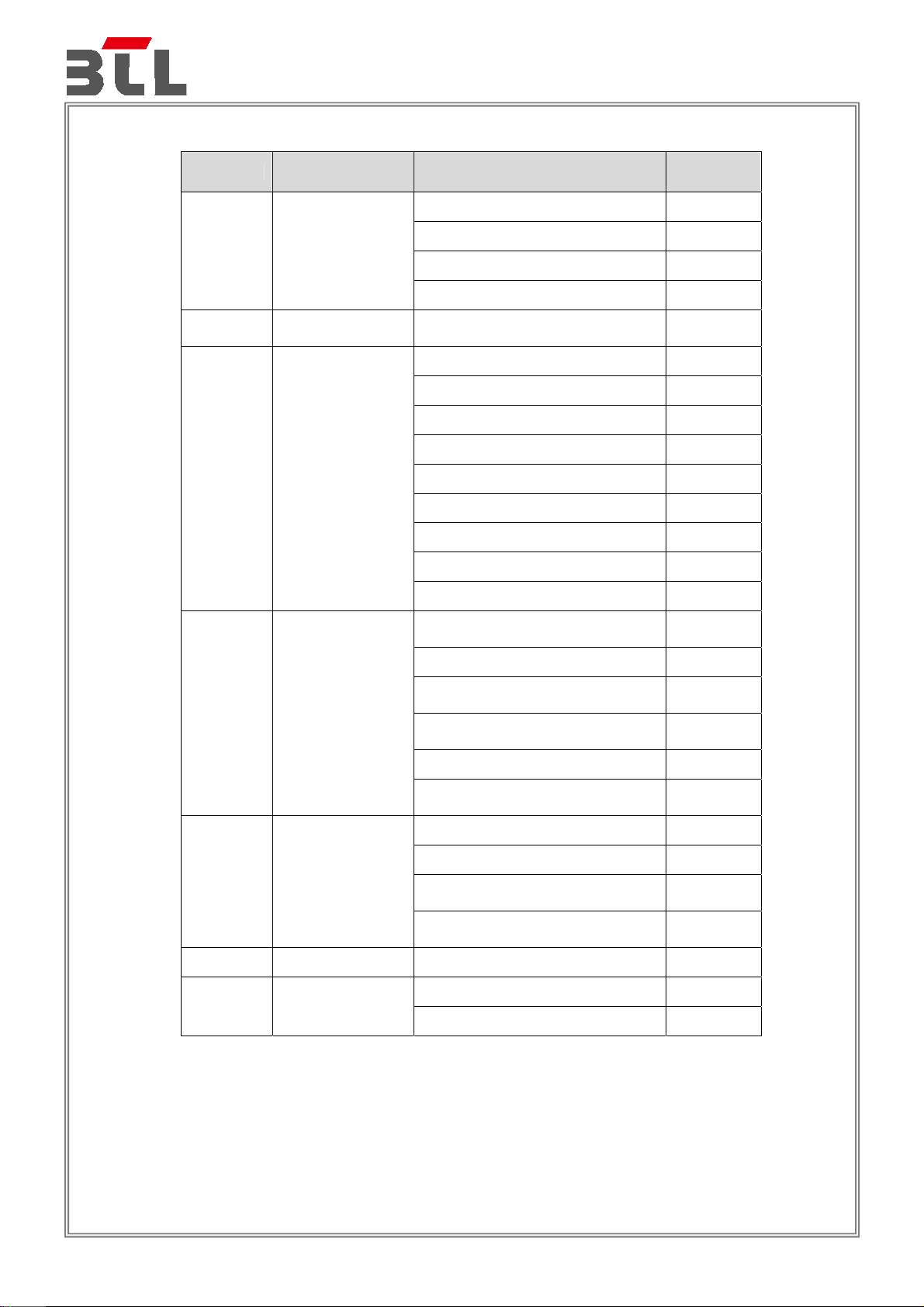
Surge immunity
IEC 61000-4-5
(Surge)
Continuous induced RF
disturbances
IEC 61000-4-6
(CS)
Port Type: unshielded symmetrical
Apply: lines to ground
Primary protection is Intended
±1 kV and ±4 kV
10/700(5/320)Tr/Th μs
Primary protection is not Intended
±1 kV
10/700(5/320) Tr/Th μs
Port type: coaxial or shielded
Apply: shield to ground
±0.5 kV
1.2/50(8/20) Tr/Th μs
line to reference ground for each
individual line:
±0.5 kV(peak)
1.2/50(8/20) Tr/Th μs
±1 kV(peak)
1.2/50(8/20) Tr/Th μs
(line to line)
±2 kV(peak)
1.2/50(8/20) Tr/Th μs
(line to earth or ground)
0.15 MHz to 10 MHz
3V(unmodulated, r.m.s),
10 MHz to 30 MHz
3V to 1V(unmodulated, r.m.s),
30 MHz to 80 MHz
1V(unmodulated, r.m.s),
1kHz 80%, AM
150 source impedance
0.15 MHz to 10 MHz
3V(unmodulated, r.m.s),
10 MHz to 30 MHz
3V to 1V(unmodulated, r.m.s),
30 MHz to 80 MHz
1V(unmodulated, r.m.s),
1kHz 80%, AM
150 source impedance
0.15 MHz to 10 MHz
3V(unmodulated, r.m.s),
10 MHz to 30 MHz
3V to 1V(unmodulated, r.m.s),
30 MHz to 80 MHz
1V(unmodulated, r.m.s),
1kHz 80%, AM
150 source impedance
Report No.: BTL-EMC-1-1907C038
Analogue/digital data ports
(NOTE 1) & (NOTE 2)
Analogue/digital data ports
(NOTE 1) & (NOTE 2)
DC network power ports
(NOTE 2)
AC mains power ports B
Analogue/digital data ports
(NOTE 2)
DC network power ports
(NOTE 2)
AC mains power ports A
C
C
B
B
A
A
Page 71 of 105
Page 72

Power frequency magnetic field
immunity
IEC 61000-4-8
(PFMF)
Voltage dips, short interruptions
and voltage variations immunity
IEC 61000-4-11
(Dip)
Broadband impulse noise
disturbances,repetitive
50 Hz or 60Hz,
1A/m(r.m.s)
Voltage dips:
Residual voltage<5%
0.5 cycle
Residual voltage<70%
25 cycle(50Hz), 30 cycle (60Hz)
Voltage interruptions:
Residual voltage<5%
250 cycle (50Hz),
300 cycle (60Hz)
0.15MHz to 0.5 MHz
107dBuV
0.5 MHz to 10 MHz
107dBuV to 36dBuV
10 MHz to 30 MHz
36dBuV to 30 dBuV
Report No.: BTL-EMC-1-1907C038
Enclosure A
B
AC Power Ports
Analogue/digital data
ports
(Applicable only to
CPE xDSL ports)
C
C
A
(BIN-R)
0.70 ms
8.3 ms(for 60Hz)
10 ms(for 50Hz)
0.15MHz to 30 MHz
110d BuV
Broadband impulse noise
disturbances,isolated
(BIN-I)
Note.
1) Applicable only to ports which, according to the manufacturer’s specification, may connect directly to outdoor
cables.
0.24 ms
10 ms
300 ms
Analogue/digital data
ports
(Apply period based on
the AC mains
frequency)
Analogue/digital data
ports
(Applicable only to
CPE xDSL ports)
Analogue/digital data
ports
(Apply all burst
durations)
A
B
B
2) Applicable only to ports which, according to the manufacturer’s specification, support cable lengths greater
than 3 m.
Page 72 of 105
Page 73

Report No.: BTL-EMC-1-1907C038
4.2 GENERAL PERFORMANCE CRITERIA
According to EN 55035 standards, the general performance criteria as following:
The equipment shall continue to operate as intended without operator intervention. No
degradation of performance, loss of function or change of operating state is allowed
below a performance level specified by the manufacturer when the equipment is used as
Criterion A
Criterion B
Criterion C
intended.The performance level may be replaced by a permissible loss of performance.
If the minimum performance level or the permissible performance loss is not specified by
the manufacturer, then either of these may be derived from the product description and
documentation, and by what the user may reasonably expect from the equipment if used
as intended.
During the application of the disturbance, degradation of performance is allowed.
However, nounintended change of actual operating state or stored data is allowed to
persist after the test.
After the test, the equipment shall continue to operate as intended without operator
intervention; no degradation of performance or loss of function is allowed, below a
performance level specified by the manufacturer, when the equipment is used as
intended.The performance level may be replaced by a permissible loss of performance.
If the minimum performance level (or the permissible performance loss), or recovery
time, is not specified by the manufacturer, then either of these may be derived from the
product description and documentation, and by what the user may reasonably expect
from the equipment if used as intended.
Loss of function is allowed, provided the function is self-recoverable, or can be restored
by the operation of the controls by the user in accordance with the manufacturer’s
instructions. Areboot or re-start operation is allowed.
Information stored in non-volatile memory, or protected by a battery backup, shall not be
lost.
Page 73 of 105
Page 74

Report No.: BTL-EMC-1-1907C038
4.3 ELECTROSTATIC DISCHARGE IMMUNITY TEST (ESD)
4.3.1 TEST SPECIFICATION
Basic Standard IEC 61000-4-2
Discharge Impedance 330 ohm / 150 pF
Required Performance B
Discharge Voltage Air Discharge: ±2kV, ±4kV, ±8kV
Contact Discharge: ±2kV, ±4kV
Polarity Positive & Negative
Number of Discharge 20 times at each test point
Discharge Mode Single Discharge
Discharge Period 1 second
4.3.2 MEASUREMENT INSTRUMENTS
Item Kind of Equipment Manufacturer Type No. Serial No. Calibrated until
1 ESD Generator TESEQ AG NSG 437 450 Sep. 07, 2020
Remark: “N/A” denotes no model name, no serial No. or no calibration specified.
All calibration period of equipment list is one year.
4.3.3 TEST PROCEDURE
The test generator necessary to perform direct and indirect application of discharges to the EUT in the
following manner:
a. The test shall be performed with single discharges. On each pre-selected point at least
10single discharges (in the most sensitive polarity) shall be applied.
NOTE 1 The minimum number of discharges applied is depending on the EUT; for products
with synchronized circuits the number of discharges should be larger.
For the time interval between successive single discharges an initial value of 1 s is
recommended. Longer intervals may be necessary to determine whether a system failure has
occurred.
NOTE 2 The points to which the discharges should be applied may be selected by means of an explor
ation carried out at a repetition rate of 20 discharges per second, or more.
Vertical Coupling Plane (VCP):
The coupling plane, of dimensions 0.5m x 0.5m, is placed parallel to, and positioned at a distance 0.1m
from, the EUT, with the Discharge Electrode touching the coupling plane.
The four faces of the EUT will be performed with electrostatic discharge.
Horizontal Coupling Plane (HCP):
The coupling plane is placed under to the EUT. The generator shall be positioned vertically at a
distance of 0.1m from the EUT, with the Discharge Electrode touching the coupling plane.
The four faces of the EUT will be performed with electrostatic discharge.
b. For TABLE-TOP equipment:
The configuration consisted of a wooden table 0.8 meters high standing on the Ground Reference
Plane. The GRP consisted of a sheet of aluminum at least 0.25mm thick, and 2.5 meters square
connected to the protective grounding system. A Horizontal Coupling Plane (1.6m x 0.8m) was placed
on the table and attached to the GRP by means of a cable with 940k total impedance. The equipment
under test was installed in a representative system as described in IEC 61000-4-2, and its cables were
placed on the HCP and isolated by an insulating support of 0.5mm thickness. A distance of1-meter
minimum was provided between the EUT and the walls of the laboratory and any other metallic
structure.
Page 74 of 105
Page 75

4.3.4 DEVIATION FROM TEST STANDARD
No deviation
4.3.5 TEST SETUP
Report No.: BTL-EMC-1-1907C038
Nearest Wall
Isol ati on Support
(0.5mm)
HCP
(1.6 m x 0. 8m)
1 m
Discharge Return
Cab le to GRP
To AC Main
80 cm
10 cm
ESD Gener ator
ESD Generator
VC P (50 cm x 50 cm )
Di schar ge R etur n
Cabl e to GRP
EUT
470 KO
Non-Conductive Table
470 KO
Ground Reference Plane (GRP) Bonded to PE
Page 75 of 105
Page 76

Report No.: BTL-EMC-1-1907C038
4.3.6 TEST RESULTS
Test Voltage AC 230V/50Hz
Test Mode Mode 1
Mode Air Discharge Contact Discharge
2kV 4kV 8kV - kV 2kV 4kV - kV
Location P N P N P N P N P N P N P N
1
2
3
4
5
6
Criteria B - B -
Result B - N/A -
Mode
Location P N P N P N P N P N P N
Left side
Right side
Front side
Rear side
Criteria B - B -
Result A - A -
Note:
1) P/N denotes the Positive/Negative polarity of the output voltage.
2) N/A - denotes test is not applicable in this test report
A A A A A A
A A A A A A
A A A A A A
A A A A B B
A A A A A A
A A A A A A
HCP Contact Discharge VCP Contact Discharge
2kV 4kV - kV 2kV 4kV - kV
A A A A
A A A A
A A A A
A A A A
- -
- -
- -
- -
- - - - - - - -
- - - - - - - -
- - - - - - - -
- - - - - - - -
- - - - - - - -
- - - - - - - -
A A A A
A A A A
A A A A
A A A A
- -
- -
- -
- -
Page 76 of 105
Page 77

Report No.: BTL-EMC-1-1907C038
PHOTO(S) SHOWN THE LOCATION(S) OF ESD EVALUATED
Page 77 of 105
Page 78

Report No.: BTL-EMC-1-1907C038
Page 78 of 105
Page 79

Report No.: BTL-EMC-1-1907C038
4.4 RADIATED, RADIO-FREQUENCY, ELECTROMAGNETIC FIELD IMMUNITY TEST (RS)
4.4.1 TEST SPECIFICATION
Basic Standard IEC 61000-4-3
Required Performance A
Frequency Range 80 MHz - 1000 MHz,
1800 MHz, 2600 MHz, 3500 MHz, 5000MHz
Field Strength 3 V/m(unmodulated, r.m.s)
Modulation 1 kHz Sine Wave, 80%, AM Modulation
Frequency Step 1% of fundamental
Polarity of Antenna Horizontal and Vertical
Test Distance 3 m
Antenna Height 1.55 m
Dwell Time 3 seconds
4.4.2 MEASUREMENT INSTRUMENTS
Item Kind of Equipment Manufacturer Type No. Serial No. Calibrated until
1 Antenna ETS 3142C 47662 Mar. 23, 2020
2* Amplifier AR 50S1G4A 326720 Apr. 08, 2021
MXG Analog Signal
3
4* Power amplifier MILMEGA AS1860-50 1064834 Aug. 20, 2020
5
6* Power amplifier MILMEGA 80RF1000-250 1064833 Aug. 20, 2020
7
Remark: “N/A” denotes no model name, no serial No. or no calibration specified.
Generator
Microwave Log.-Per.
Antenna
Measurement
Software
“*” calibration period of equipment list is three year.
Except * item, all calibration period of equipment list is one year.
Agilent N5181A MY49060710 Aug. 03, 2020
TESEQ STLP 9149 9149-277 Mar. 23, 2020
TOYO
IM5/RS Ver
3.8.050
N/A N/A
4.4.3 TEST PROCEDURE
The EUT and support equipment are in a fully-anechoic chamber.
The testing distance from antenna to the EUT was 3 meters.
For TABLE-TOP equipment:
The EUT installed in a representative system as described in IEC 61000-4-3 was placed on a
non-conductive table 0.8 meters in height. The system under test was connected to the power and signal
wire according to relevant installation instructions.
The other condition as following manner:
a. The field strength level was 3 V/m(unmodulated, r.m.s).
b. The frequency range is swept from 80 MHz to 1000 MHz, with the signal 80%amplitude modulated with
a 1 kHz sine wave. The rate of sweep did not exceed 1.5x 10⁻³ decade/s. Where the frequency range is
swept incrementally, the step size was 1% of fundamental.
c. The dwell time at each frequency shall be not less than the time necessary for the EUT to be able to
respond.
d. The test was performed with the EUT exposed to both vertically and horizontally polarized fields on
each of the four sides.
4.4.4 DEVIATION FROM TEST STANDARD
No deviation
Page 79 of 105
Page 80

4.4.5 TEST SETUP
a) For Continuous induced RF disturbances
Report No.: BTL-EMC-1-1907C038
Page 80 of 105
Page 81

4.4.6 TEST RESULTS
Test Voltage
Report No.: BTL-EMC-1-1907C038
AC 230V/50Hz
Test Mode
Mode 1
Frequency Range
(MHz)
80 - 1000 H / V 3V/m
1800, 2600,
3500, 5000
(±1%)
RF Field
Position
H / V 3V/m
R.F.
Field Strength
Modulation Azimuth Criterion Result
0
AM Modulated
1000Hz, 80%
AM Modulated
1000Hz, 80%
90
A A
180
270
0
90
A A
180
270
Page 81 of 105
Page 82

Report No.: BTL-EMC-1-1907C038
4.5 ELECTRICAL FAST TRANSIENT/BURST IMMUNITY TEST (EFT)
4.5.1 TEST SPECIFICATION
Basic Standard IEC 61000-4-4
Required Performance B
Test Voltage AC mains power ports: ±1 kV
Analogue/digital data ports: ±0.5 kV
Polarity Positive & Negative
Impulse Frequency 5 kHz: except for xDSL ports.
Impulse Wave shape 5/50 ns
Burst Duration 15 ms
Burst Period 300 ms
Test Duration 1 min.
4.5.2 MEASUREMENT INSTRUMENTS
Item Kind of Equipment Manufacturer Type No. Serial No. Calibrated until
1 Capacitor Clamp Thermo KeyTek CCL 502215 Aug. 03, 2020
Fast Transient Burst
2
Remark: “N/A” denotes no model name, no serial No. or no calibration specified.
Simulator
All calibration period of equipment list is one year.
Prima
EFT61004T
A
PR190741004 Aug. 27, 2020
4.5.3 TEST PROCEDURE
For TABLE-TOP equipment:
The configuration consisted of a wooden table (0.8m high) standing on the Ground Reference Plane and
should be located 0.1 m+/- 0.01m above the Ground Reference Plane. The GRP consisted of a sheet of
aluminum (at least 0.25mm thick and 2.5m square) connected to the protective grounding system. A
minimum distance of 0.5m was provided between the EUT and the walls of the laboratory or any other
metallic structure.
The other condition as following manner:
a. Both positive and negative polarity discharges were applied.
b. The duration time of each test sequential was 1 minute
4.5.4 DEVIATION FROM TEST STANDARD
No deviation
Page 82 of 105
Page 83

4.5.5 TEST SETUP
Report No.: BTL-EMC-1-1907C038
Page 83 of 105
Page 84

4.5.6 TEST RESULTS
Test Voltage
Report No.: BTL-EMC-1-1907C038
AC 230V/50Hz
Test Mode
AC Power Port
Analogue/digital
data ports
Mode 1
EUT Ports Tested Polarity
+ 5 kHz
Line (L)
- 5 kHz
+ 5 kHz
Neutral (N)
- 5 kHz
+ 5 kHz
L+N
- 5 kHz
EUT Ports Tested Polarity
+ 5 kHz B
WAN/LAN1
- 5 kHz B
Repetition
Frequency
Repetition
Frequency
Test Level
1kV
A
A
A
A
A
A
Test Level
0.5 kV
Criterion Result
B
B
B
Criterion Result
B B
A
A
A
Page 84 of 105
Page 85

Report No.: BTL-EMC-1-1907C038
4.6 SURGE IMMUNITY TEST (SURGE)
4.6.1 TEST SPECIFICATION
Basic Standard IEC 61000-4-5
Required Performance
Wave-Shape 1.2/50(8/20) Tr/Th μs combination wave
Test Voltage
Generator Source
Impedance
Phase Angle, Polarity
and Number of Tests
Pulse Repetition Rate 1 time / min
B(AC mains power ports)
AC mains power ports: ±0.5 kV, ±1 kV
2 Ω of the low-voltage power supply network.
Five positive pulses line-to-neutral at 90°phase
Five negative pulses line-to-neutral at 270°phase
Five positive pulses line-to-earth at 90°phase
Five negative pulses line-to-earth at 270°phase
Five negative pulses neutral-to-earth at 90°phase
Five positive pulses neutral-to-earth at 270°phase
4.6.2 MEASUREMENT INSTRUMENTS
Item Kind of Equipment Manufacturer Type No. Serial No. Calibrated until
1 System mainframe Schaffner NSG 2050
2 CDN EMC PARTNER CDN-UTP8 40 Mar. 10, 2020
3
Remark: “N/A” denotes no model name, no serial No. or no calibration specified.
Lightning Surge
Generator
All calibration period of equipment list is one year.
Prima
SUG61005T
B
200729-619L
PR190854067 Aug. 27, 2020
U
Aug. 03, 2020
4.6.3 TEST PROCEDURE
a. For EUT power supply:
The surge is to be applied to the EUT power supply terminals via the capacitive coupling network.
Decoupling networks are required in order to avoid possible adverse effects on equipment not under
test that may be powered by the same lines, and to provide sufficient decoupling impedance to the
surge wave. The power cord between the EUT and the coupling/decoupling networks shall be 2meters
in length (or shorter).
b. For test applied to unshielded unsymmetrically operated interconnection lines of EUT :
The surge is applied to the lines via the capacitive coupling. The coupling /decoupling networks shall not
influence the specified functional conditions of the EUT. The interconnection line between the EUT and
the coupling/decoupling networks shall be 2 meters in length (or shorter).
c. For test applied to unshielded symmetrically operated interconnection /telecommunication lines of EUT :
The surge is applied to the lines via gas arrestors coupling. Test levels below the ignition point of the
coupling arrestor cannot be specified. The interconnection line between the EUT and the
coupling/decoupling networks shall be 2 meters in length (or shorter).
4.6.4 DEVIATION FROM TEST STANDARD
No deviation
Page 85 of 105
Page 86

4.6.5 TEST SETUP
Report No.: BTL-EMC-1-1907C038
Page 86 of 105
Page 87

4.6.6 TEST RESULTS
Test Voltage
Report No.: BTL-EMC-1-1907C038
AC 230V/50Hz
Test Mode
Wave Form
EUT Ports Tested
AC L – N
Mode 1
Polarity Phase
+
-
90
270
1.2/50(8/20)Tr/Thμs
Voltage
0.5kV 1kV -- kV -- kV
A A - A A - -
Criterion Result
B A
Page 87 of 105
Page 88

Report No.: BTL-EMC-1-1907C038
4.7 IMMUNITY TO CONDUCTED DISTURBANCES, INDUCED BY RADIO-FREQUENCY FIELDS
TEST (CS)
4.7.1 TEST SPECIFICATION
Basic Standard IEC 61000-4-6
Required Performance A
Frequency Range&Field
Strength
Modulation 1 kHz Sine Wave, 80%, AM Modulation
Frequency Step 1% of fundamental
Dwell Time 3 seconds
0.15 MHz - 10 MHz: 3V (unmodulated, r.m.s.)
10 MHz - 30 MHz: 3V to 1V (unmodulated, r.m.s.)
30 MHz - 80 MHz: 1V (unmodulated, r.m.s.)
4.7.2 MEASUREMENT INSTRUMENTS
Item Kind of Equipment Manufacturer Type No. Serial No. Calibrated until
1 Power CDN FCC
2 Signal Line CDN FCC
TEST SYSTEM
FOR CONDUCTED
3
4
Remark: “N/A” denotes no model name, no serial No. or no calibration specified.
AND RADIATED
IMMUNITY
Measurement
Software
All calibration period of equipment list is one year.
TESEQ NSG 4070B 37513 Aug. 03, 2020
Farad
FCC-801-M2
/M3-16A
FCC-801-T8
-SRJ45
EZ-CS
(V2.0.1.4)
100270 Mar. 10, 2020
100273 Mar. 10, 2020
N/A N/A
4.7.3 TEST PROCEDURE
The EUT and support equipment, are placed on a table that is 0.8 meter above a metal ground plane
measured 1m*1m min. and 0.65mm thick min.
The other condition as following manner:
a. The field strength level was 3 V (unmodulated, r.m.s.)
b. The frequency range is swept from 150 kHz to 80 MHz, with the signal 80%amplitude modulated with a
1 kHz sinewave. The rate of sweep did not exceed 1.5x 10⁻³ decade/s. Where the frequency range is
swept incrementally, the step size was 1% of fundamental.
c. The dwell time at each frequency shall be not less than the time necessary for the
EUT to be able to respond.
4.7.4 DEVIATION FROM TEST STANDARD
No deviation
Page 88 of 105
Page 89

4.7.5 TEST SETUP
Report No.: BTL-EMC-1-1907C038
Page 89 of 105
Page 90

4.7.6 TEST RESULTS
Test Voltage
Report No.: BTL-EMC-1-1907C038
AC 230V/50Hz
Test Mode
Tes t P o r t s
(Mode)
AC mains power ports
Analogue/digital data
ports
(WAN/LAN1)
Mode 1
Freq.Range
(MHz)
0.15 - 10 3V
30 - 80 1V
0.15 - 10 3V
10 - 30 3V to 1V
30 - 80 1V
Field Strength Modulation Criteria Results
AM Modulated
1000Hz, 80%
AM Modulated
1000Hz, 80%
A A 10 - 30 3V to 1V
A A
Page 90 of 105
Page 91

Report No.: BTL-EMC-1-1907C038
4.8 POWER FREQUENCY MAGNETIC FIELD IMMUNITY TEST (PFMF)
4.8.1TEST SPECIFICATION
Basic Standard IEC 61000-4-8
Required Performance A
Frequency Range 50/60Hz
Field Strength 1 A/m
Observation Time 1 minute
Inductance Coil Rectangular type, 1mx1m
4.8.2 MEASUREMENT INSTRUMENTS
Item Kind of Equipment Manufacturer Type No. Serial No. Calibrated until
Magnetic Field test
1
2
Remark: “N/A” denotes no model name, no serial No. or no calibration specified.
Generator
Magnetic Field
immunity loop
All calibration period of equipment list is one year.
FCC
Thermo KeyTek
F-1000-4-8-
G-125A
F-1000-4-8/9
/10-L-1M
4032 Mar. 10, 2020
4024 Mar. 10, 2020
4.8.3 TEST PROCEDURE
For TABLE-TOP equipment:
The equipment shall be subjected to the test magnetic field by using the induction coil of standard
dimension (1 m x 1 m). The induction coil shall then be rotated by 90 degrees in order to expose the
EUT to the test field with different orientations.
The other condition as following manner:
a. The equipment cabinets shall be connected to the safety earth directly on the GRP via the earth
terminal of the EUT.
b. The cables supplied or recommended by the equipment manufacturer shall be used. 1 meter of all
cables used shall be exposed to the magnetic field.
4.8.4 DEVIATION FROM TEST STANDARD
No deviation
Page 91 of 105
Page 92

4.8.5 TEST SETUP
Report No.: BTL-EMC-1-1907C038
Page 92 of 105
Page 93

4.8.6 TEST RESULTS
Test Voltage
Report No.: BTL-EMC-1-1907C038
AC 230V/50Hz
Test Mode
50Hz
Test Mode Test Level Antenna aspect Duration Criteria Results
Enclosure 1 A/m X 60s A A
Enclosure 1 A/m Y 60s A A
Enclosure 1 A/m Z 60s A A
60Hz
Test Mode Test Level Antenna aspect Duration Criteria Results
Enclosure 1 A/m X 60s A A
Enclosure 1 A/m Y 60s A A
Enclosure 1 A/m Z 60s A A
Mode 1
Page 93 of 105
Page 94

Report No.: BTL-EMC-1-1907C038
4.9 VOLTAGE DIPS, SHORT INTERRUPTIONS AND VOLTAGE VARIATIONS IMMUNITY TEST
(DIP)
4.9.1 TEST SPECIFICATION
Basic Standard IEC 61000-4-11
Required Performance
Interval between Event Ten seconds
Phase Angle 0°/180°
Test Cycle 3 times
Voltage dips:
B (For <5% residual voltage, dips)
C (For 70% residual voltage, dips)
C (For <5% residual voltage, Interruptions)
4.9.2 MEASUREMENT INSTRUMENTS
Item Kind of Equipment Manufacturer Type No. Serial No. Calibrated until
1 Cycle Sag Simulator Prima
Remark: “N/A” denotes no model name, no serial No. or no calibration specified.
All calibration period of equipment list is one year.
DRP61011T
A
PR19076452 Aug. 27, 2020
4.9.3 TEST PROCEDURE
The EUT shall be tested for each selected combination of test levels and duration with a sequence of
three dips/interruptions with intervals of 10 s minimum (between each test event). Each representative
mode of operation shall be tested. Abrupt changes in supply voltage shall occur at zero crossings of the
voltage waveform.
4.9.4 DEVIATION FROM TEST STANDARD
No deviation
4.9.5 TEST SETUP
Page 94 of 105
Page 95

4.9.6 TEST RESULTS
Test Voltage
Report No.: BTL-EMC-1-1907C038
AC 100V/50Hz, AC 230V/50Hz, AC 240V/50Hz
Test Mode
Item Residual Voltage Cycle Criteria Results
Voltage dips
Voltage dips 70% 25 C A
Voltage Interruption
Item Residual Voltage Cycle Criteria Results
Voltage dips
Voltage dips 70% 25 C A
Voltage Interruption
Mode 1
<5%
<5%
<5%
<5%
AC 100V/50Hz
0.5 B A
250 C C
AC 230V/50Hz
0.5 B A
250 C C
Item Residual Voltage Cycle Criteria Results
Voltage dips
Voltage dips 70% 25 C A
Voltage Interruption
<5%
<5%
AC 240V/50Hz
0.5 B A
250 C C
Page 95 of 105
Page 96
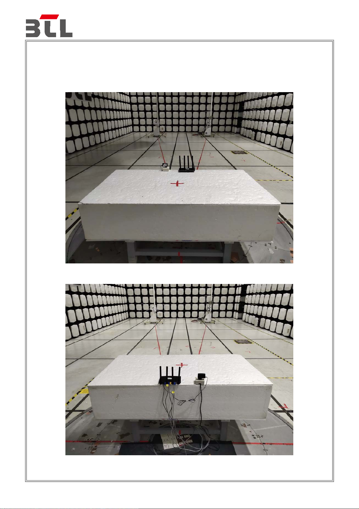
5. EUT TEST PHOTO
Report No.: BTL-EMC-1-1907C038
Radiated emissions up to 1 GHz
Page 96 of 105
Page 97

Report No.: BTL-EMC-1-1907C038
Radiated emissions above 1 GHz
Page 97 of 105
Page 98

Report No.: BTL-EMC-1-1907C038
Conducted emissions AC mains power port
Page 98 of 105
Page 99

Report No.: BTL-EMC-1-1907C038
Asymmetric mode conducted emissions
Page 99 of 105
Page 100

Report No.: BTL-EMC-1-1907C038
Harmonic current
Voltage fluctuations (Flicker)
Page 100 of 105
 Loading...