

Page 1
Page 2

* CONTENTS*
1. Rules for Safe Marker Handling . . . . . . . . . . . . . . . . . .1
2. Included with your BT Delta Elite™ . . . . . . . . . . . . . . .1
3. Introduction and Specifications . . . . . . . . . . . . . . . . . .2
4. Getting started and Basic Adjustments . . . . . . . . . . . .2
5. Rip Clip . . . . . . . . . . . . . . . . . . . . . . . . . . . . . . . . . . . . .3
6. Apex™ Barrel . . . . . . . . . . . . . . . . . . . . . . . . . . . . . . . .4
7. E-Grip . . . . . . . . . . . . . . . . . . . . . . . . . . . . . . . . . . . . .4
8. General Maintenance . . . . . . . . . . . . . . . . . . . . . . . . . .5
9. Disassembly . . . . . . . . . . . . . . . . . . . . . . . . . . . . . . . . .5
10. Reassembly/ Storage and Transportation . . . . . . . . . .6
11. Troubleshooting . . . . . . . . . . . . . . . . . . . . . . . . . . . . . .7
12. Parts List . . . . . . . . . . . . . . . . . . . . . . . . . . . . . . . . . . .8
13. Diagram . . . . . . . . . . . . . . . . . . . . . . . . . . . . . . . . . . .10
14. Warranty Information . . . . . . . . . . . . . . . . . . . . . . . . .12
Page 3

Page 4
* READ OWNERS MANUAL BEFORE USING.*
Rules of Safe Marker Handling
1. Treat every marker as if it were loaded.
2. Never look down the barrel of a paintball marker.
3. Keep your finger off the trigger until ready to shoot.
4. Never point the marker at anything you don’t wish to shoot.
5. Keep the marker on “safe” until ready to shoot.
6. Keep the barrel blocking device in/ on the marker’s muzzle when not shooting.
7. Always remove paintballs and propellant source before disassembly.
8. After removing propellant source, point marker in safe direction and discharge
until marker is degassed.
9. Store the marker unloaded and degassed in a secure place.
10. Follow warnings listed on propellant source for handling and storage.
11. Do not shoot at fragile objects such as windows.
12. Every person within range must wear eye, face and ear protection designed
specifically to stop paintballs and meeting ASTM standard F1776.
13. Always measure your marker’s velocity before playing paintball and never
shoot at velocities in excess of 91.44 meters (300 feet-per-second).
Included with your BT Delta Elite
1. BT-Delta Elite™ with Electronic Grip
2. Apex™ Elite barrel
3. Rip-Clip™
4. 9V Battery (In the grip)
5. Loader
6. Barrel Plug
7. Owner’s Manual
8. Spare Parts kit
9. Magazine
TM
1
Page 5
TM
Congratulations on your selection of the BT Delta Elite
Delta EliteTMis made to provide you with many years of reliable performance. BT
Paintball Designs, Inc. is honored that you have chosen the BT Delta EliteTMas your
marker of choice and hope you enjoy using this high quality product.
paintball marker. The BT
BT Delta Elite™ Specifications
Model- Delta Elite™
Barrel- Apex™
Stock- Adjustable
Loader- Rip-Clip™
Caliber-68
Action- Semi-Auto, Ramping, and Full-Auto
Air Source- CO
Batteries- One 9 volt and 4 AA’s
Cycle Rate-13 BPS Max
Main Body Material- Aluminum
Accuracy Range- 150+ ft.
2 or Compressed Air (HP Output only)
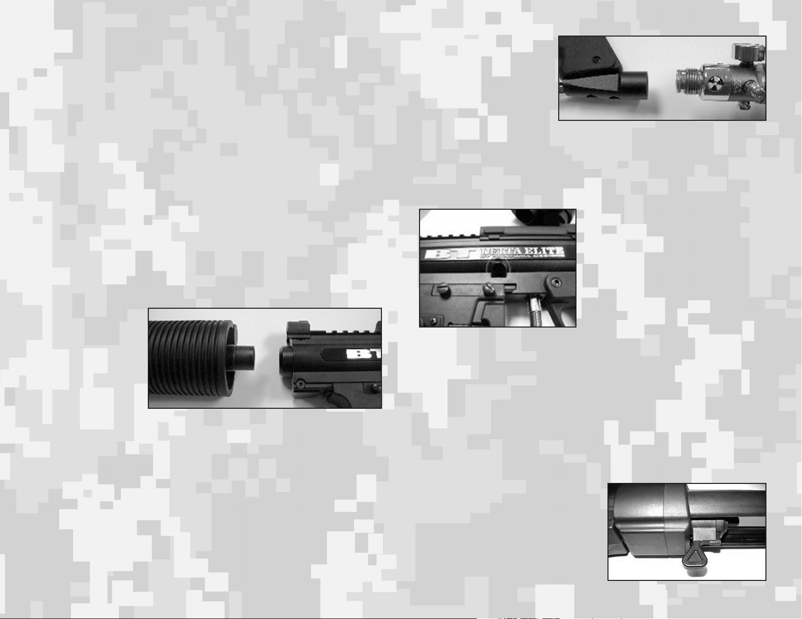
Getting Started and Basic Adjustments
Barrel Installation
1. Make sure marker is
degassed, hopper
removed, no paintballs in the feed port
or breech and the EGrip is turned off.
2. While pointing marker
in a safe direction,
place the threaded
end of the barrel into the front opening of the marker body.
3. Turn the barrel clockwise until it stops (do not over tighten).
4. Adjust the barrel accessories if necessary.
5. Install a barrel blocking device. This can be a barrel plug or other such device that
prevents the accidental discharge of a paintball.
Air Cylinder Installation
1. Make sure the barrel blocking device is properly installed and the E-grip is turned
off.
2. While pointing the marker in a safe direction, cock the marker by pulling the cock-
ing knob located on the left side of the marker back until it clicks and stops.
3. Release the cocking knob.
4. The marker is now cocked.
5. Locate the air cylinder
adapter. The BT Delta
Elite™ cylinder adapter is
located at the base of the
pistol grip.
6. Position the BT Delta
Elite™ so that the air cylinder adapter is pointed
upwards while keeping the muzzle of the marker pointed in a safe direction.
7. Insert the threaded cylinder valve end into the adapter.
8. Without pushing the cylinder, twist the cylinder clockwise and allow the threads to
draw the cylinder into the marker until it stops. Your marker is now charged.
Note: If cylinder is installed incorrectly, you can damage the threads on your marker
and cylinder. Make sure to align them properly before installing cylinder.
Velocity Adjustment
1. Always check the velocity of the marker
prior to playing paintball. Different playing fields may have different maximum
velocity limits. At no time should you
shoot at velocities above 300 feet-persecond.
2. Put on eye protection designed specifically for paintball and make sure that
anyone within range of the BT Delta
Elite™ does the same.
3. While pointing the marker in a safe direction, remove the barrel blocking device.
4. Point the BT Delta Elite™ over a chronograph that will measure the velocity of the
paintballs discharged by the marker.
5. Turn the Marker’s E-Grip On.
6. Pull the trigger and check the reading on the chronograph.
7. Locate the velocity adjuster screw on the center of BT Delta Elite™, under the
name Plate.
8. Using a 5/32" hex key, turn the screw inward or clockwise to reduce the velocity,
and outward or counterclockwise to increase the velocity of the paintballs discharged from the marker.
Note: Different Types/Brands of Paintballs will affect your markers velocity. Check
your markers velocity before each day of
play.
Stock Adjustment
1. Push the stock adjustment lever to the
left and adjust the stocks length by pulling
or pushing on the back of the stock
2. Make sure the lever springs back to the
right to lock it in position.
2
Page 6

Magazine Adjustment
It is possible to slide the Magazine assembly to your liking
1. Remove the 2 screws and metal plate
2. Slide the magazine assembly to new
location.
3. Reinstall the plate and screws, making
sure they are going into a body notch.
4. Tighten screws.
Loading Paintballs
1. Put on an eye protective device designed specifically for paintball and make sure
that anyone within range of the marker does the same.
2. Make sure the E-Grip is turned off and that a Barrel Blocking device is installed.
3. Load quality .68 caliber paintballs (leave some room for paintballs to move about
inside loader).
Rip-Clip™
Loader Installation
Insert the loader onto the
Rip-Clip as indicated.
Turn the loader Counterclockwise until it locked
firmly.
(Figures 6-8)
Figure 6 Figure 7 Figure 8
Activating the Rip-Clip™
Locate the power button on the rear control panel. To turn on, press the button. The
green LED comes on while the button is pressed; now release button. The green
LED will now flash again for one second, go off, then flash quickly 1, 2, or 3 times
indicating the speed it is currently set to. The motor will spin for a second and the
loader is now ready to use. Do NOT fire your marker until after the initial motor spin
has completed. Firing during this period can disrupt the auto-adjusting sound sensitivity and cause the hopper not to work properly. The green LED will flash repeatedly
while the unit is on to show it is ready. If the LED flashing changes to red, then the
batteries are low and need to be replaced.
Battery Installation
1. Remove the screw on top of battery door.
2. Install 4 x AA batteries following the polarity marking.
3. Reinstall the battery door screw. (Figure 1)
Rip-Clip Installation
1. Loosen up the spring screws. (Figure 2)
2. Clip on the BT Delta Elite™ between the 2 sight rails.
(Figure 3)
3. Make sure the feed holes are aligned. (Figure 4)
4. Tighten up the spring screws. (Figure 5)
Figure 2 Figure 3 Figure 4
Figure 1
Figure 5
To turn off, press and hold until the loader gives a RED indication. Release the button and loader will power down to the OFF state.
Setting the Speed
1. When the Rip-Clip is first turned on, while the LED flashes for one long second,
press and hold the power button again during this flash.
2. When done properly, the LED will now change to red and you can release the button.
3. The LED will only stay red for about 15 seconds, then change back to its flashing
green sequence for regular operation if no buttons are pressed.
4. To set the speed during the red LED phase, push and release the button the number of times necessary based on what speed you desire.
5. Press once for normal slow speed, twice for faster normal speed, and three times
for fastest speed. Each time you press and release the button during this sequence,
the press of the button should last about one second.
6. If done too quickly, the board may not be set to the speed you desire. When done
correctly, the red LED will go off, then flash the same number of times the button
was pressed, indicating which speed it is now set to.
7. The motor will now spin up at the speed it is set to, it will stop, and now the speed
is set and the unit is ready to use.
Note: Always use good name brand batteries. Using other types of batteries will
affect the Rip Clips performance.
3
Page 7

Specifications:
Power requirements: 4AA batteries (not included)
Capacity: 200+ paintballs
Feed Rate: 20bps+
Construction: Nylon
Features:
Auto-Off 1 Hour
Low Battery Indicator
Ultra-Quiet Belt Drive
Tactile Feedback Power Button
Delta Elite Apex™ Barrel
The Apex barrel is the most advanced barrel in
the world. You can adjust the barrel to shoot in
different directions and set it to give you greater
distance than any standard barrel.
Setting the Apex™ Barrel Ramp
1. Start with the Ramp in the OFF position
(toward the back of barrel)
2. Follow all safety and paintball loading instruction for safe use.
3. Go to your fields shooting range or other approved area.
4. Gradually adjust the Ramp forward until you see the balls start to change there
trajectory. The further you move the Ramp forward; the balls will have higher
degree of curve.
E-Grip
The E-Grip has 3 different firing modesSemi-Auto, Ramping and Full-Auto. The
modes are changed by removing the left
side grip and adjusting the dip switches
located in the grip frame. The Delta Elite
comes in Ramping mode from the factory
and the Jumper in the frame must be
removed to lock the firing mode to semiauto. The E-Grip has an automatic shut-off
after 1 hour of inactivity.
Note: Always use good name brand batteries. Using other types of batteries will
affect the marker performance.
Adjusting Direction of Shots
1. Adjust the Apex front by turning it.
2. Turning it right will give you a right hook
3. Turning it left will give you a left hook
4. Rotating it 180 degrees will give you a drop shot.
5. The standard position will give you a long shot.
Note: It will be necessary to adjust the Ramp setting on the Apex barrel to the paint
you are using. Different brands/types of paintballs will have a slightly different size.
This will affect the amount of curve you get.
Features
1. On/Off capability.
2. Hit previously untouchable targets with new curve feature.
3. Adjustable ramp switch - choose the desired level of the curve.
4. Left hook, right hook, drop shot and long flat trajectory shots with a twist of the
barrel.
5. Easy to dial in targets and change the level of curve.
4
Adjusting the Sear Height
To adjust the sear height, there is a set
screw in the lower vertical arm of the sear
that contacts the front of the solenoid. If it
is necessary to raise the sear to engage
the rear bolt, insert a 0.50" allen wrench
past the side of trigger and turn the allen
wrench counter clockwise. Make adjustments while the trigger frame is off the
receiver (body) and the marker is
degassed. Look down from the top of
frame to help locate the set screw. Only
turn the allen wrench 1/8 turn at a time and check engagement after each adjustment. Once the sear begins to engage the rear bolt, turn the set screw an additional
half to 1 full turn.
Page 8

General Maintenance
Once the BT Delta is unloaded and the air cylinder is removed, you can use a damp
cloth to wipe off paint, oil, dirt and debris. You can also use warm water to rinse the
marker clean, but be careful not to get the internal components wet.
Once your marker is clean and dry you can re-oil using a light, premium marker oil.
(Note: Petroleum based and aerosol products can damage your markers o-rings.
DO NOT USE ANY PETROLEUM BASED OR AEROSOL PRODUCTS ON YOUR
MARKER.) To access the rear bolt and linkage arm you must remove the left receiver half. (See marker disassembly section.)
Body Sight Rails
Removal
1. Remove the Rip
Clip and Barrel
assembly.
2. Slide the small
sight rail spacer off.
2. Loosen the 3 screws with a Phillips screwdriver on the left side of the sight rail.
3. Slide the sight rail toward the front of the marker and remove.
Note: It may not be necessary to loosen the 3 screws, see if it slides off first.
Disassembly Instructions
Removing the Rip-Clip™
1. Turn both locking screws counter-clockwise until they stop.
2. Gently pull then tilt the Rip-Clip away
from the body and remove.
Note: The Locking screws are spring
loaded.
Removing Rip-Clip Anti Jam
1. Remove Rip Clip from marker
2. Pull out the inner sleeve, located in the
left side feed port.
3. Gently lift the anti-jam assembly out.
Note: If you remove the Rip Clips drive
cone, it will be necessary to Pre-Load the
drive spring.
Preloading the Rip-Clip’s Drive Cone
Spring
Rotate the cone clockwise until the upper and lower spring tabs hit each other. You
should now have both spring tabs pressed together. Lift the drive cone SLIGHTLY
and rotate it clockwise up and over the drive cup’s tab (taking the upper spring tab)
with it. Snap the drive cone down with the drive spring tab on the right side of the
drive cup's tab and install the top screw. The drive cone spring is now pre-loaded
and will snap back properly when wound up.
Apex Barrel Disassembly
1. Remove barrel assembly from marker.
2. Loosen the 4 Phillips screws located at the
front of the barrel.
3. Pull the two sides apart and take notice of
the internal configuration.
4. If needed, wash the parts with warm water.
Removing Foregrip
1. Remove the barrel assembly from marker.
2. Remove the foregrip retention pin.
3. Pull the front of the foregrip down and gently pull it
forward.
Note: It is recommended that you DO NOT remove
the Barrel from the complete barrel assembly, as you
will lose the factory alignment to your marker.
Magazine and Magazine Holder Removal
1. Push on the release tab to remove the magazine.
2. Remove the 2 screws and metal plate.
3. Slide the Magazine holder toward the front of
the marker and remove.
Trigger Frame Removal
1. Adjust the stock all the way out.
2. Remove the two grip retention screws from the E-Grip.
3. Push out the Acorn shoulder nuts with
a small hex wrench or screwdriver
nuts if they do not fall out.
4. Gently pull the frame down from the
body
5
Page 9

ASA Removal
1. Remove the 2 screws which go thru the ASA with a 1/8" allen wrench.
Stock Removal
(See body disassembly instructions )
Body disassembly (Internal components)
To fully access the internal components, these parts must be removed first:
- Barrel assembly
- Rip-Clip and loader
- Sight rails
- Magazine assembly
- Grip frame
Receiver (Body) Separation
Make sure the marker is in the un-cocked (forward position) before taking body
apart.
1. Remove the Cocking Handle Cover (rubber bonnet).
2. Lay on a flat surface with the name plate facing up.
3. Remove the four upper receiver retention screws.
4. Lift name plate receiver away from other receiver half.
Note: The stock will be under some spring tension and may spring out when the top
name plate receiver is lifted off.
Note: The retention screw located below the cocking handle slot is longer than the
rest.
Stock Removal
Once the body is
separated, simply
lift the stock from
the body. Be careful not to lose any
of the rear parts
when removing
the stock.
Hammer, Cocking Handle and
Connecting Rod Removal
1. Rotate Hammer counter-clockwise.
2. Remove Connecting Rod.
3. Remove Cocking Handle.
4. Slide Hammer rearward and
remove.
Barrel Adapter, Ball Retainer and Bolt Removal
1. Lift away Barrel Adapter (and barrel if still installed).
2. Lift out Ball Retainer.
3. Slide Bolt forward and remove
Reassembly/ Storage and Transportation
Reassembly
To reassemble the marker, reverse the Disassembly instructions starting with the
barrel adapter, ball retainer and bolt removal. While reassembling the marker, you
should oil all O-rings and sliding parts. All parts and o-rings returned to the marker
should be free of debris and visual nicks and scratches which can alter the performance of the marker. All screws returned to the marker must be tightened so there is
no chance of them vibrating loose.
Storage and Transportation
1. BT Delta must be clear of all paint and propellant when not being used.
2. Be sure to have marker in “SAFE MODE” when not in use.
3. Make sure barrel blocking devise is in place.
4. Store BT Delta™ and propellant in cool dry place.
5. Keep your BT Delta™ away from children without proper supervision.
6. Your BT Delta™ must be free of all paint and not attached to a propellant source
while being transported to and from the playing field.
7. Observe and obey all local, state and federal laws concerning the transportation
of paintball markers. For information concerning any of the laws in your area, contact your local law enforcement.
6
Page 10

Troubleshooting
Marker double firing or going full auto • Air cylinder low on air • Get air cylinder filled
PROBLEM DIAGNOSIS SOLUTION
PROBLEM DIAGNOSIS SOLUTION
• Rear bolt oring worn or damaged • Replace rear bolt oring
• Rear bolt or sear worn • Inspect both for wear and replace if needed
• Rear bolt has no oil • Oil rear bolt oring area with paintball oil
• Bad valve • Service or replace valve
• Sear height is misadjusted • Adjust sear height
Marker does not recock • Rear bolt oring worn or damaged • Replace rear bolt oring
Marker leaking out of barrel • Valve leaking • Service or replace valve
Marker leaking at ASA • Tank oring damaged or missing • Replace tank oring
E-Grip is not working • Battery is low on power • Install new battery
Rip-Clip is not working • Battery is low on power • Install new battery
Marker is breaking paint • Velocity is too high • Lower velocity by turning screw clockwise
Marker is double feeding • Ball detent is damaged • Replace ball detent
Paintballs not feeding into marker • Rip-Clip not installed correctly • Check Rip-Clip is installed correctly
• Rear bolt oring is dry • Oil rear bolt oring area with paintball oil
• Power tube is damaged • Replace power tube
• Sear height is misadjusted • Adjust sear height
• Marker internals clogged • Clean dirt and/or broken paintballs from inside receiver
• Tank or ASA damaged • Replace tank and/or asa if needed
• Battery is of low quality • Buy better name brand batteries
• Sear height is misadjusted • Adjust sear height
• Board connectors are loose • Check that connectors are plugged in fully
• Electronics are damaged • Replace damaged parts
• Battery is of low quality • Buy better name brand batteries
• Batteries are installed incorrectly • Check the polarity markings
• Drive cone is not pre-loaded • Pre-loaded drive cone spring
• Paint is of low quality or old • Try better fresh paint
• Ball detent damaged or backwards • Replace detent or check if its in backwards
• Apex barrel is dirty • Clean apex barrel
• Apex ramp is set to high • Lower the ramp setting
• Rip-Clip is not turned on • Turn on Rip-Clip
Velocity is low (Do NOT Exceed 300 FPS) • Velocity screw is in too far • Turn the screw counter-clockwise to increase velocity
• Air source is low • Get air cylinder filled
• Power tube is damaged • Replace power tube
• Drive spring is weak • Install a stiffer drive spring
Velocity is high (Do NOT Exceed 300 FPS) • Velocity screw is out too far • Lower velocity by turning screw clockwise
• Drive spring is too stiff • Install a lighter drive spring
7
Page 11

Parts List BT4 = BT-4 Parts (all models apply) • BTE = Elite Parts (other models my apply) • BTRC = Rip Clip Parts • BTEG = E-Grip Parts • BTA = Apex Parts
QTY DESCRIPTION PART # DIAGRAM # QTY DESCRIPTION PART # DIAGRAM #
RECEIVER PARTS
1 LEFT UPPER RECEIVER BT4-1 1
1 RIGHT UPPER RECEIVER BT4-3 3
1 POWER TUBE BT4-5 5
1 DRIVE SPRING GUIDE BT4-7 7
1 BOLT HANDLE BT4-8 8
1 REAR BOLT BT4-9 9
1 BOLT PLUG BT4-10 10
1 BARREL ADAPTER BT4-12 12
1 VALVE BODY BT4-13 13
1 INTERNAL VALVE SEAT BT4-14 14
1 PLUNGER CAP BT4-15 15
1 REAR VALVE SEAT BT4-16 16
1 VALVE STEM BT4-17 17
1 CUP SEAL BT4-18 18
1 EXPANSION CHAMBER PLUG BT4-21 21
2 LOWER RECEIVER NUT BT4-24 24
2 LOWER RECEIVER SCREW BT4-25 25
1 FRONT BOLT BT4-32 32
1 LINKAGE ARM BT4-33 33
4 SHORT RECEIVER BOLT BT4-37 37
6 RECEIVER NUTS BT4-38 38
2 VALVE SCREW BT4-39 39
1 VELOCITY SCREW BT4-40 40
2 TANK ADAPTER NUTS BT4-45 45
1 FRONT BOLT ORING BT4-46 46
2 INTERNAL VALVE O-RING BT4-47 47
2 REAR BOLT &VALVE O-RING BT4-48 48
1 SHOCK ABSORBER O-RING BT4-49 49
1 TANK ADAPTER BT4-51 51
1 GAS LINE BT4-58 58
1 LONG TANK ADAPTER BOLT BT4-61 61
1 SHORT TANK ADAPTER BOLT BT4-62 62
1 VALVE SNAP RING BT4-64 64
1 INTERNAL VALVE SCREW BT4-66 66
1 DRIVE SPRING BT4-69 69
1 BARREL ADAPTER O-RING BT4-73 73
1 NAME PLATE (ALL TYPES) BT4-74 74
1 BALL DETENT (RUBBER) BT4-75 75
1 BOLT HANDLE RUBBER BONNET BT4-76 76
RIP-CLIP PARTS
1 RIP CLIP BODY BTRC-1 R-1
1 BOTTOM COVER BTRC-2 R-2
1 BATTERY COVER ASSEMBLY BTRC-3 R-3
1 BALL SLEEVE BTRC-4 R-4
1 RAIL LOCKING ARM BTRC-5 R-5
1 MOTOR W/PULLEY AND HARNESS BTRC-6 R-6
1 PULLEY GEAR BTRC-7 R-7
1 LARGE GEAR BTRC-8 R-8
1 DRIVE BELT BTRC-9 R-9
2 RIP DRIVE AND DRIVE CONE SCREW BTRC-10 R-10
1 RIP DRIVE BTRC-11 R-11
5 BOTTOM COVER SCREWS BTRC-12 R-12
1 BATTERY COVER NUT BTRC-13 R-13
2 E-CLIP BTRC-14 R-14
2 BEARING BTRC-15 R-15
1 ANTI JAM ASSEMBLY BTRC-16 R-16
1 ANTI JAM SPRING BTRC-17 R-17
1 DRIVE SHAFT BTRC-18 R-18
1 SPRING HOUSING BTRC-19 R-19
1 DRIVE CONE SPRING BTRC-20 R-20
1 DRIVE CONE BTRC-21 R-21
1 PULLEY GEAR PIN BTRC-22 R-22
2 RAIL LOCKING ASSEMBLY BTRC-23 R-23
1 BATTERY COVER SCREW BTRC-24 R-24
1 BATTERY COVER WASHER BTRC-25 R-25
2 RAIL LOCKING NUTS BTRC-26 R-26
1 POLARITY STICKER BTRC-27 R-27
2 LOWER BATTERY SPRING TABS BTRC-28 R-28
1 ON/OFF BUTTON PAD BTRC-29 R-29
1 CIRCUIT BOARD BTRC-30 R-30
E-GRIP PARTS
1 FRAME BTEG-1 G-1
1 GRIP BTEG-2 G-2
1 SOLENOID (COMPLETE) BTEG-3 G-3
1 CIRCUIT BOARD BTEG-4 G-4
1 BATTERY HARNESS BTEG-5 G-5
1 TRIGGER SWITCH W/HARNESS BTEG-6 G-6
1 RUBBER MAGNET HOLDER BTEG-7 G-7
1 TRIGGER BTEG-8 G-8
1 TRIGGER SET SCREW BTEG-9 G-9
1 SEAR BTEG-10 G-10
1 SEAR SET SCREW BTEG-11 G-11
1 SEAR SPRING BTEG-12 G-12
8
Page 12

QTY DESCRIPTION PART # DIAGRAM # QTY DESCRIPTION PART # DIAGRAM #
4 GRIP SCREW BTEG-13 G-13
1 LED COVER BTEG-14 G-14
1 ON/OFF BUTTON COVER BTEG-15 G-15
1 TRIGGER PIN BTEG-16 G-16
1 SEAR PIN BTEG-17 G-17
2 TRIGGER SWITCH PIN BTEG-18 G-18
2 CIRCUIT BOARD SCREWS BTEG-19 G-19
1 SOLENOID RETURN MAGNET BTEG-20 G-20
1 SOLENOID SCREW BTEG-21 G-21
1 SOLENOID HOLDER BTEG-22 G-22
1 CAPACITOR FOAM BTEG-23 G-23
BT ELITE- PARTS
1 BARREL SIGHT BODY BTE-1 B-1
1 LEFT SIGHT RAIL HALF BTE-2 E-2
1 FORE GRIP BTE-3 B-3
1 RIGHT SIGHT RAIL HALF BTE-4 E-4
1 BARREL (ONLY) BTE-5 B-5
1 FRONT SIGHT RAIL BTE-6 E-6
1 FRONT SIGHT BTE-7 B-7
1 FORE GRIP RETENTION PIN BTE-8 B-8
1 SLING HOOK BTE-9 B-9
1 FRONT SIGHT SCREW BTE-10 B-10
1 REAR SIGHT BODY BTE-11 E-11
1 FRONT SIGHT NUT BTE-12 B-12
1 MAGAZINE (COMPLETE) BTE-13 M-13
2 BARREL SET SCREW (LARGE) BTE-14 B-14
1 BARREL PIN BTE-15 B-15
1 BARREL SET SCREW (MEDIUM) BTE-16 B-16
1 BARREL SET SCREW (SMALL) BTE-17 B-17
1 COCKING ARM BTE-18 B-18
3 SIGHT RAIL SCREW BTE-19 E-19
3 SIGHT RAIL ALIGNMENT PIN BTE-20 E-20
1 SLING HOOK NUT BTE-21 B-21
1 SIGHT BODY SCREW BTE-22 E-22
1 SIGHT BODY NUT BTE-23 E-23
1 BARREL SPRING BTE-24 B-24
1 BARREL SPRING STRUT BTE-25 B-25
1 REAR SIGHT (COMPLETE) BTE-26 E-26
1 BARREL SIGHT STRIKER BTE-27 B-27
1 MAGAZINE HOLDER LEFT BODY BTE-28 M-28
1 MAGAZINE HOLDER RIGHT BODY BTE-29 M-29
1 MAGAZINE HOLDER RETENTION ARM BTE-30 M-30
1 MAGAZINE HOLDER HOOK BTE-31 M-31
1 RELEASE SLEEVE BTE-32 M-32
1 RELEASE ARM STOP BTE-33 M-33
1 RELEASE ARM BTE-34 M-34
2 MAGAZINE RETENTION SCREWS BTE-35 M-35
1 RELEASE MECHANISM BTE-36 M-36
3 HOOK SCREW BTE-37 M-37
1 MAGAZINE SPRING BTE-38 M-38
1 MAGAZINE HOLDER BODY PIN BTE-39 M-39
3 MAGAZINE HOLDER BODY SCREW BTE-40 M-40
2 MAGAZINE HOLDER NUT BTE-41 M-41
1 RELEASE MECHANISM SCREW BTE-42 M-42
1 STOCK FRONT BTE-43 S-43
1 STOCK BODY BTE-44 S-44
1 RIGHT STOCK ARM BTE-45 S-45
1 LEFT STOCK ARM BTE-46 S-46
1 STOCK BACK BTE-47 S-47
1 STOCK BACK COVER BTE-48 S-48
4 STOCK BACK SCREW BTE-49 S-49
1 STOCK REAR ARM HOLDER BTE-50 S-50
1 STOCK ADJUSTER CAP BTE-51 S-51
1 STOCK ADJUSTER BTE-52 S-52
2 STOCK FRONT SCREW BTE-53 S-53
1 STOCK SPRING BTE-54 S-54
1 STOCK ADJUSTER BACK BTE-55 S-55
1 STOCK ADJUSTER SCREW BTE-56 S-56
1 STOCK SLING HOOK BTE-57 S-57
1 STOCK FRONT O-RING BTE-58 S-58
1 BARREL REAR CAP BTE-59 B-59
APEX PARTS
1 TOP BODY BTA-1 A1
1 BOTTOM BODY BTA-2 A2
1 RUBBER INSERT BTA-3 A3
1 METAL ARM BTA-4 A4
1 RAMP SWITCH BTA-5 A5
4 SCREW BTA-6 A6
2 APEX STICKER BTA-7 A7
2 BARREL O-RING BTA-8 A8
9
Page 13

10
Page 14

11
Page 15

BT PAINTBALL DESIGNS, INC.
LIMITED WARRANTY
BT PAINTBALL DESIGNS, INC. warrants the replacement of any original part due to defect in material and/or workmanship of this marker. This
warranty will be in effect for twelve (12) months for parts and twelve (12) months for labor following the original date of purchase for the original
purchaser. Such warranty service will be provided only if the warranty registration card included with this manual is filled in completely and on file
at BT PAINTBALL DESIGNS, INC. All other service will be duly charged for and returned via UPS C.O.D.
BT PAINTBALL DESIGNS, INC. will replace without charge any original part that is determined by BT PAINTBALL DESIGNS, INC. to be defective under the terms of this warranty. However, shipping charges are not covered hereunder. Failure due to an accident, abuse, neglect, modification, normal wear, operator error, maintenance by other than an authorized BT PAINTBALL DESIGNS, INC. dealer, or use of parts
inconsistent with the use originally intended for the marker as sold, is not covered by this warranty.
There are no other warranties or guarantees, expressed or implied, made by BT PAINTBALL DESIGNS, INC. on this marker. The sole and exclusive liability of BT PAINTBALL DESIGNS, INC. and/or its authorized dealers, affiliates, or agents pursuant to this warranty will be for repair or
replacement of the defective part; incidental or consequential damages are expressly excluded hereunder.
BT PAINTBALL DESIGNS, INC., its authorized dealers, affiliates, or agents, will not be liable under this warranty, nor under any state or federal
law, or the common law or otherwise for any damage or failure, including personal injury, resulting from such use and/or alteration. This warranty gives you specific legal rights, and you may also have other rights that may vary from state to state.
12
For warranty parts, service or information contact:
BT PAINTBALL DESIGNS, INC.
3217 EAST WASHINGTON BLVD.
FORT WAYNE, INDIANA 46803
260-424-9100
info@btpaintball.com
Page 16

This is not a toy. Misuse may cause serious
injury or death. Eye protection designed specifically for paintball must be worn by the user and
persons within range. Recommend 18 years of
age or older to purchase. Persons under 18
years of age must have adult supervision.
READ THIS MANUAL BEFORE USING.
 Loading...