

Page 1

BRYSTON
OWNER’S MANUAL
Instructions For Bryston
ST Series Amplifiers
Model 9B ST
Page 2

GENERAL INSTRUCTIONS
Warranty Information:
Thank you for choosing a Bryston product. We
welcome any suggestions you may have, or
comments regarding the operation of your am
plifier. We consider you, our customer, to be
Bryston’s most important resource, and your
opinion is very much appreciated.
Bryston products are warranted to be free from
manufacturing defects for a minimum of 20,
(twenty), years from the original date of manu
facture. This includes all parts, labor and one
way return shipping. This warranty covers the
original owner and any subsequent owners. The
warranty is retroactive for any Bryston product
purchased within the last twenty years. Tamper
Bryston 9B-ST Amplifier Description:
The Bryston 9B-ST is a multi-channel power
amplifier consisting of five independent ampli
fier modules, each with its own power trans
former and +/-60V power supply. Each audio
channel provides connections for balanced or
ing by anyone other than factory authorized
personnel voids the warranty. Warranty service
may be obtained by returning the unit to any
authorized Bryston dealer or distributor. You
may also contact the Bryston factory or national
service offices directly at the location listed on
the rear page of this manual.
Please keep the original box and all packing
material. This will ensure the amplifier is pro
tected in the unlikely event you have a problem
and must return it for service. No warranty card
is necessary to initiate your coverage. Please
refer to the back page for more detailed war
ranty information.
single ended input and will supply a minimum
of 120 watts of power into 8 ohms or 200
watts into 4 ohms.
A remote power control option is available on
THX versions.
Installation Setup And Recommendations:
PROVIDE ADEQUATE VENTILATION
Do not place the amplifier in an enclosed un
ventilated area. Allow at a minimum, 3 inches of
space at the top, sides and back as your ampli
fier relies on convection cooling and ample air
flow is required. Be sure cool air can flow freely
through the amplifier. Do not install near heat
sources such as other power amplifiers, hot air
vents, radiators, etc.
All Bryston amplifiers contain high quality, dedi
cated circuitry in their power supplies to reject RF,
line spikes and other power-line problems. Bryston
power amplifiers do not require any specialized
PLEASE REFER TO: “BRYSTON’S SAFETY MANUAL” FOR FURTHER OPERATING INSTRUCTIONS.
power line conditioners. Simply plug the amplifier
directly into its own wall socket.
Make sure the power switch on the front of the
amplifier is in the off (out) position. Plug the power
cord (female end) into the rear of the amplifier,
then insert the male end into the wall outlet. Finally,
upon completion of the installation activate the 9B
power switch only after all other equipment is pow
ered up.
Note:
If rack-mounting the 19 inch version please
ensure that the rear of the 9B is well supported.
Page 2
Page 3
BRYSTON 9B ST MANUAL
9B ST Rear Panel
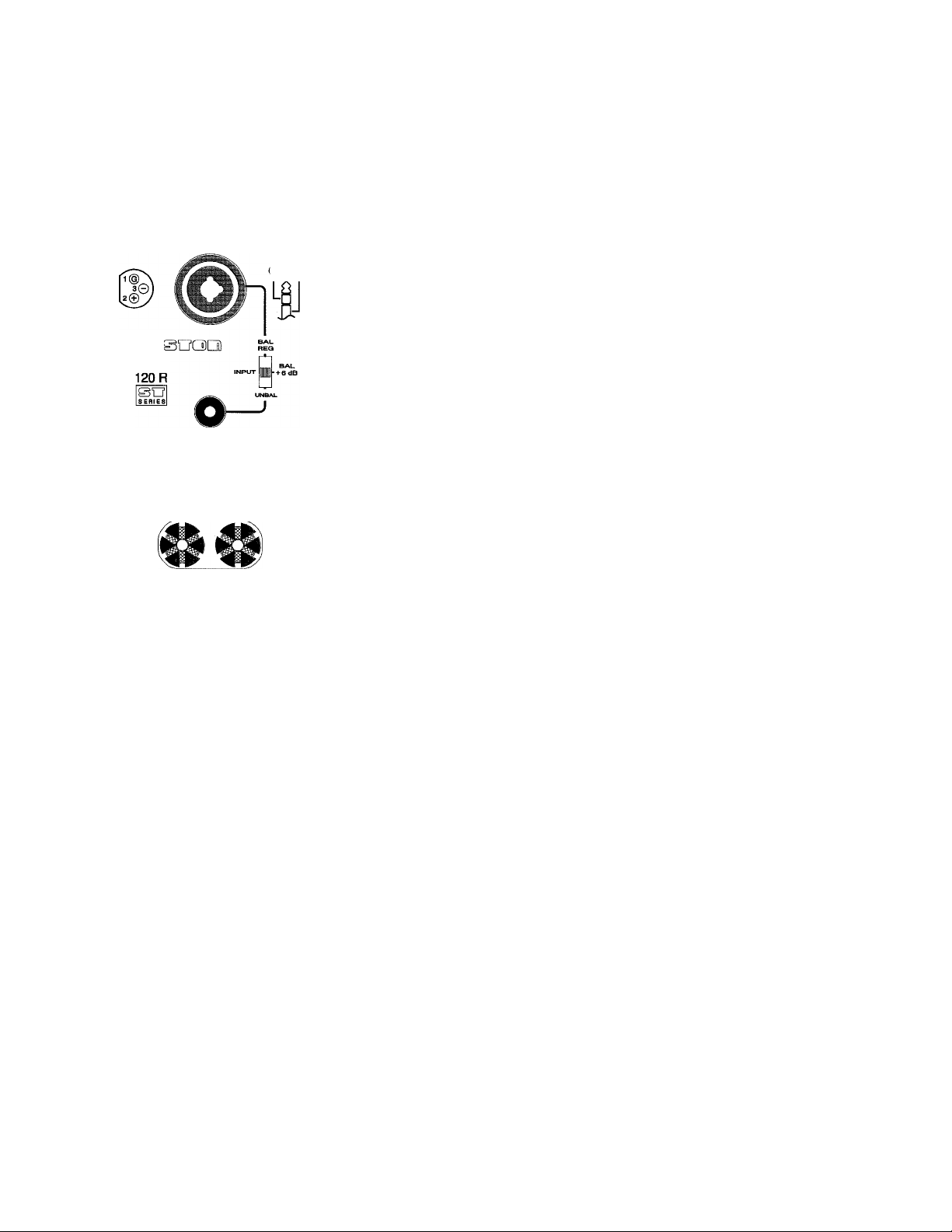
Input:
The 9B has two inputs, one for a
balanced source,and one for
single ended or un-balanced
source. The BAL input connec
Qqo
OD
"WARNING!
RISK OF HAZARDOUS ENERQYl
MAKE PROPER SPE/^ER CONNECTIONS.
SEE OPERATING MANUAL BEFORE USING.
tor will accept either a 3 pin
‘XLR’ type or a 1/4” Tip/Ring/
Sleeve type. The in phase (+)
terminal is pin 2 on the ‘XLR’
and tip on the TRS. The input
impedance is 15K ohms. The
input pins are gold plated. Input
sensitivity is selectable using the
‘INPUT’ slide switch. In the ‘BAL
REG’ position 2 Volts in = 100
Watts / 8 ohms output. This is
the recommended setting when
using Bryston pre-amplifiers or
Balanced Vs Unbalanced:
Balanced cable interconnects should be used
whenever possible, as they provide common
mode noise protection from external electrical
interference, and with active balanced outputs
a 6 dB higher signal level flows in the cable.
The unbalanced cable interconnect is provided
for pre-amplifiers without balanced output. Un
balanced cables should be kept to 10 feet or
less. In general never use longer cables than
necessary, never coil excess cable length, and
run signal wires away from and never parallel
to AC power or speaker cables.
Output:
Gold plated output binding posts provide three
different interconnect options. Stripped bare
wire up to 8 Ga. can be passed through the
hole in the binding post and held in place by
tightening the post knob. Additional tightening
pressure can be achieved using a coin in the
slots of the knob. Copper wire is malleable and
may require further tightening a month or
any pre-amplifier having active
balanced outputs. This setting
also produces the lowest ampli
fier noise floor.
The ‘BAL +6 dB” setting adds 6
db of gain to provide an input
sensitivity of 1 Volt in = 100
Watts / 8 ohms output. This set
ting is primarily for balanced out
puts that are transformer cou
pled, or other low level sources.
The ‘UNBAL’ setting selects the
gold plated ‘RCA’ type tip/sleeve
connector. The input impedance
is 50K ohms. The output is in
phase with the input and the
sensitivity is 1 Volt in = 100
Watts into 8 ohms output.
two after initial installation. When using bare
wire watch out for fine wire fragments shorting
from one wire to the other.
Wire terminated with banana plugs,spade lugs,
or pins are also accommodated by the binding
posts. We recommend gold plated connectors
to prevent corrosion and signal distortion.
The red (+) binding post is the output and
normally will be connected to the red (+) con
nector on the loudspeaker. The black (-) bind
ing post is ground and should be connected to
the black (-) connector on the loudspeaker.
Speaker wire should be kept as short as practi
cal and should never be terminated with con
nectors that may become confused with AC
power connectors. Speaker cables should be
dressed away from input and power cables,
and even each other when runs are long.
The minimum speaker ioad on the
amplifier is 4 ohms.
Page:
Page 4

BRYSTON 9B ST MANUAL
Clipping indicators:
All Bryston amplifiers use bicolor LEDs with
green indicating power on and flashing red indi
cating actual overload or distortion. Upon powerup the 9B’s LED’s will remain “red” until all volt
ages stabilize and the unit comes out of mute
and the LED turns green.
If the LED indicator contains a substantial red
content, when program is present, it should be
considered as a sign that the level is too high and
may cause speaker damage if it continues. It
should be remembered that the Bryston ST se
ries are powerful amplifiers, and that it is possible
to damage almost any speaker if an amplifier is
used in a thoughtless or abusive manner. Brys
Bryston 9B ST Remote Power Control - THX units only
r REMOTE POWER CONTROL^
LOCAL
REMOTE
DC -I
OR
AC
h:
SELECT 'LOCAL' WHEN NOT
USING REMOTE POWER CONTROL
4-12V
The 9B ST remote power control
function allows the user to link the
power on/off of the 9B to an exter
nal preamplifier, processor, or
other control device. This is useful
in installations, such as home the
ater, for powering up multiple am
plifiers, often at distant locations
from the source.
FRONT PANEL POWER SWITCH
MUST BE 'ON' WHEN USING
REMOTE POWER FUNCTION.
Located on the back panel of the
9B ST is a two screw terminal
input connector. The amplifier
ton will not be responsible for damage caused in
this manner.
The clip-sensing circuit uses an AC comparator
to detect any source of signal distortion including
clipping, short circuits in cabling, excessive DC or
supersonic signals, whether at the input or out
put. Most conditions which could cause the red
LED to light for more than a moment or two can
be dangerous to your loudspeakers and should
be corrected immediately.
If a specific LED remains “red" without signal
present, it may indicate a thermal overload
condition and the channel is shut down until
safe operating temperatures return.
can be powered-up by applying
4-12 Volts (AC or DC of either
polarity) connected to the termi
nals of the jack. This jack will
accept 1/4 inch stripped wire
ends, inserted into the square
holes provided, and the adjacent
screws carefully tightened to
hold them in place. The input
current remains at less than 3
ma regardless of voltage, there
fore 22 Ga wire is sufficient.
The front panel power switch must be left in
the "on" position (in), at all times for the am
plifier to operate in remote power control
mode.
In ‘REMOTE’ position the amplifier can only
be turned on by applying a remote controi
voltage of 4-12 volts.
In the ‘LOCAL’ position the amplifier will not
respond to remote control voltage, only the
front panel power switch.
At aii times the power can be turned off by
using the front panel power switch.
Page 4
Page 5

BRYSTON m ST MAKUAL
Typical Surround Sound Hookup:
Shown below; is a typical hookup between a
surround sound processor and the 9BST. We
show balanced interconnects which we rec
ommend especially when the 9B is located
more than 10 feet from the processor. The
connections would be similar using the unbal
anced interconnects. This suggested layout
when viewed from the front of the 9B has the
center channel in the middle and left and right
front channels adjacent to the center with left
and right surround speakers juxtaposed to
the appropriate left and right front channels.
This particular setup allows you to easily
monitor the status of each individual channel
as the power LED’s will correlate with the
positions of the speakers in most rooms (see
diagram below). It should be noted that be
cause each channel on the 9B is identical
any channel can be operated with any input
and arranged as required.
Page 6

V-
■■■-■-
m m m
For Bryston amplifiers with rear panel gain adjustment including the THX designation
the correct THX position is as indicated on the back panel.
9B-ST
The “BAL THX” or the “UNBAL THX” position
(see diagram) is the correct setting for the slide
switch. Do not place the slide selector in the
middle or +6 dB position if installed in an
authorized THX system.
©O’
S ERI ES
LUCASFILM
Thx
"WARNING!
RISK OF HAZARDOUS ENERGY!
MAKE PROPER SPEAKER CONNECTIONS.
SEE OPERATING MANUAL BEFORE USING.
120W8Q
BAL
-i-6dB
TMX
The 9B professional version provides a rotary
gain control which must be turned fully clockwise
if installed in a THX system and the slide switch
above (see diagram) must also be in either the
“BAL THX” or “UNBAL THX” position.
RO. Box 2170, 677 Neal Drive,
Peterborough, Ont., Canada K9J 7Y4
Tel: (705) 742-5325 * Fax: (705) 742-0882
EDoiasnoQ]
ODpro
SO
S ERi ES
LUCA8FILM
Thx
"WARNING!
RISK OF HAZARDOUS ENERGY!
MAKE PROPER SPEAKER CONNECTIONS.
SEE OPERATING MANUAL BEFORE USING.
120W80
©(^©
UNBAL
THX
__
;
LEVEL
-14 dB THX
Page 7

BRYSTON 20 -YEAR WARRANTY
Bryston products are warranted to be free
from manufacturing defects for a minimum
of twenty years from the original date of
manufacture. This includes parts, labour
and return shipping to the first owner and
ail subsequent owners. Warranty coverage
is automatic and commences with the
original date of manufacture which is kept
on file at Bryston.
In the event of a defect or malfunction,
Bryston will remedy the problem by repair
or replacement, as we deem necessary, to
restore the product to full performance.
This warranty is considered void if the
defect, malfunction or failure of the
product or any component part was
caused by damage ( not resulting from
BRYSTON SERVICE CANADA:
24 STEINWAY BLVD,. UNIT 48
ETOBICOKE, ONTARIO
CANADA M9W 6T8
PHONE: 416-675-2585
FAX: 416-675-3103
BRYSTON LTD.
P.O. BOX 2170,577 NEAL DRIVE
PETERBOROUGH,ONTARIO
CANADA K9J 7Y4
PHONE: 705-742-5325
FAX: 705-742-0882
a defect or malfunction ) or abuse while
in the possession of the customer.
Tampering by persons other than factory
authorized service personnel, or failure
to fully comply with Bryston operating
instructions, voids the warranty.
This warranty gives you specific legal
rights and you may also have other
rights which may vary from province to
province and country to country.
FOR BRYSTON SERVICE OUTSIDE CANADA:
CONTACT YOUR LOCAL DISTRIBUTOR
OR CHECK OUR WEB SITE AT:
www.bryston.ca
OR CALL BRYSTON DIRECTLY AT:
PHONE: 705-742-5325
FAX: 705-742-0882
BRYSTON SERVICE U.S.A.
30 COVENTRY ST.
NEWPORT VERMONT.
U.S.A. 05855
PHONE: 802-334-1201
FAX: 802-334-6658
Specifications: 9B-120-R channel
power rating:
input impedance:
balanced
unbalanced
sensitivity:
bal input reg
bal input +6
unbal
distortion:
Thd + N
IMD
noise
power consumption:
all channels at full power with 8 ohm loads = 900 VA.
all channels at full power with 4 ohm loads = 1600VA.
all channels idle = 100 VA.
.007%
.002%
107db 20Hz to 22kHz bandpass
120 Watts into 8 Q
200 Watts into 4 Q
15kQ
50 k n
2 Volt in = 100 Watts/8 Q
1 Volt in = 100 Watts/8 Q
1 volt in = 100 Watts / 8 Q
20Hz to 20kHz at 120 Watts / 8 Q
60 Hz + 7kHz mixed 4 to 1
9B-120-P channel
The 9B-PRO version provides for input attenua
tion of up to 14dB by adjusting the ‘LEVEL’
control. Full attenuation versions are also avail
able. Level controls are not available on THX
versions.
THX
THX MODELS ARE MANUFACTURED UNDER
LICENSE FROM LUCASFILM LTD. THX IS A
TRADEMARK OF LUCASFILM LTD.
dimensions
rack mount models
17” models
shipping weight
19” X 17” X 5.25”
17”x 17” X 5.25”
75 lbs
 Loading...