

Page 1

10B
CROSSOVER
OWNER’S MANUAL
for Models
10B-STD, 10B-SUB & 10B-LR
Page 2

INTRODUCTION:
The 10B crossover is available in three stock versions; 10B-SUB incorporating frequencies more
suitable to sub-woofer applications (40Hz to 500hz), 10B-STD which is more applicable to speakers
requiring frequency control in the mid-band and tweeter areas (70Hz to 4500Hz) and the 10B-LR,
which uses plug in resistor programming cards to set the crossover frequency. Both the 10B-SUB
and 10B-STD crossovers include a mode called Mono Low Pass (see below) which replaces the Two
Way Mono (Linkwitz-Riley) mode in older model 10B’s. The Two Way Mono mode (see below) is
retained in the 10B-LR allowing for very steep (non Linkwitz-Riley) 8th order lters.
MONO LOW PASS MODe (10B-SUB AND 10B-STD ONLy):
The 10B-STD and 10B-SUB crossovers generate a summed low pass output signal by rst summing
or adding together the left channel and right channel input signals to form a left plus right (L+R) signal. If the MODE switch (located on the rear panel) is in the Mono Low Pass position then this L+R
signal is fed into both of the low pass lter sections (Left and Right) available in the 10B. As a result,
the common low pass output can be taken from either of the two low pass (LP) outputs; either left LP
out or right LP out. These outputs are designated as Left and Right for convenience only. If the low
pass output used is the one designated as the left channel, then the crossover frequency and slope
(or lter order) switches on the left side of the unit’s front panel (as viewed from the front) will control
the low pass lter parameters. Likewise, if the right channel low pass output is used, then the right
channel switches will control its lter parameters. There is no interaction between the two sets of controls. If one of the two low pass lters is not used, then settings of its crossover frequency and slope
switches are irrelevant and will have no affect on the performance of the other lter sections of the
crossover. The two high pass lter sections (left and right) operate independently in Mono low Pass
mode.
STeReO MODe:
As in the older versions of the 10B, the stereo mode provides two, two way crossovers wherein the
left input is fed into a separate low pass lter and a separate high pass lter, both of which are inde-
pendently adjustable from the front panel controls. Likewise, the right input signal is fed into a sepa-
rate low pass lter and a separate high pass lter, both of which are independently adjustable from
the front panel controls. All four lters have separate output connectors on the rear panel. There is no
interaction whatsoever between left and right channels or between low pass and high pass lters.
THRee WAy MONO MODe (10B-LR ONLy) :
Available only in the 10B-LR (Linkwitz-Riley lters), this mode is the same as in the older model 10B.
The four lter sections (two low pass and two high pass) of the 10B are combined to form a single
channel three way crossover providing one low pass, one mid or band pass and one high pass lter.
The mid (or band pass) lter is formed by combining the left channel high pass and the right channel low pass lters into a single lter wherein the lower end of the pass band is determined by the left
channel high pass controls and the upper end of the pass band is determined by the right channel low
pass controls
Only the LEFT channel input is used in Three Way Mono mode. The left channel low pass output
provides the low pass output. The mid or band pass output is taken from the right channel low pass
output connector and the high pass is taken from the right channel high pass connector. All lter
slopes are 24dB per octave, Linkwitz-Riley alignment.
PROGRAMMING THe 10B-LR CROSSOveR:
The crossover points in the 10B-LR are set by inserting small programming boards (4 per channel)
each containing 2 resistors. See illustration “10B LINKWITZ-RILEY STEREO CROSSOVER” and on
page 7 and document “10B-FREQ-RES-TABLES.doc”
Page 3

POWeR AMPLIFIeRS:
When power ampliers of different power capabilities are used, the woofers will likely be driven by
the most powerful amplier and the tweeters by the least powerful amplier since the woofers can
generally be expected to be less efcient. When power ampliers of equivalent power capabilities
are used in a bi-amped system, and when the power amps employ totally separate power supplies
for each channel (as all Bryston power ampliers do) it is desirable to place each power amplier as
close to its speaker as possible and use one channel to drive the woofer and the other to drive the
tweeter. Please note that if the power amps being used do not employ totally separate power supplies
for each channel, some envelope distortion between channels may occur since the power drawn from
the low frequency channel driving the woofer will usually be considerably greater than from the higher
frequency channel driving the tweeter.
POWeR AMPLIFIeR PLACeMeNT:
Where there is a considerable distance between the audio signal source and the speakers, it is
preferable to reduce the distance between the power ampliers and the speakers at the expense of
increasing the distance between preamp and crossover or crossover and power amplier. The low im-
pedance across the speaker lines is more likely to affect signal quality with distance than is the higher
impedance across the preamp to crossover, or crossover to power amplier cables.
BALANCeD veRSUS UNBALANCeD CABLING:
If the distance between the power amplier and crossover or crossover and preamplier is greater
than 30 feet, it may be desirable to use balanced cables to interconnect the two distant pieces of
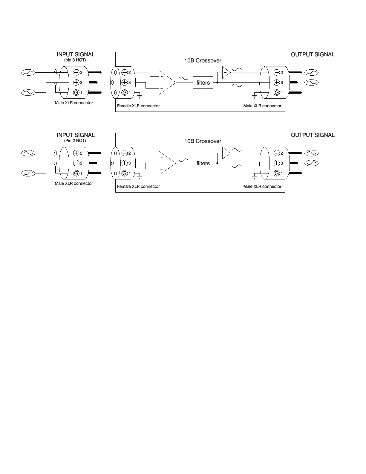
equipment as this may reduce noise pickup. To facilitate this, the 10B crossover is available with balanced inputs and outputs (PRO versions) using 3 pin XLR connectors (outputs use male connectors,
inputs use female connectors). Pin 3 is the positive (non-inverted or Hot) signal, pin 2 is the negative
(inverted or neutral) signal and pin 1 is ground.
Where a long run of balanced cable is used to interconnect the preamplier to the crossover, and the
crossover is placed within a few feet of the power amplier there is no advantage in using a balanced
interconnection between the crossover and power amplier. Balanced cabling does not reduce noise;
it merely reduces the ability of the cable to pickup noise. The balanced output of a 10B Pro crossover
can easily be used as an unbalanced output by using XLR pin 3 (positive) as the HOT line and XLR
pin 1 as the ground line.
Since there is no phase inversion in the 10B, the negative XLR output pins (#2) can be used
in the same way to achieve the same effect and the output will remain un-inverted with respect to the
input. In other words, any signal that enters the negative XLR input pin (#2) will exit the negative XLR
output pin (#2) un-inverted with respect to the input. Similarly any signal that enters the positive XLR
input pin (#3) will exit the positive XLR output pin (#3) un-inverted with respect to the input. It is for
this reason that the 10B has not been changed to comply with the AES adopted XLR pin conguration
for balanced signals (pin 3 negative, pin 2 positive and pin 1 ground) and retains its original XLR pinout of pin 3 positive, pin 2 negative and pin 1 as ground.
Note, however, that Bryston’s current production power ampliers do follow the AES convention. As the above illustrations indicate, however, the 10B PRO models do not introduce any phase
inversion and thus can be used with either pin 2 hot or pin 3 hot balanced cable systems without
changing the phase relationships of the system.
CABLeS:
Bryston supplies a variety of stock audio interface cables and will supply reasonably priced semi-
custom cables (including adapter cables and cables with custom printed identication sleeves) upon
request. Bryston’s balanced cables employ double insulated, 100% shielded twisted pair cable with
Page 4
24g stranded, tinned copper conductors and locking XLR connectors with metal shells and gold plated contacts. Unbalanced cables use single conductor shielded co-axial cable with gold plated male
phono (RCA) plugs in metal shells.
Page 5

Page 6

Page 7

Page 8

CONNeCTING 10B CROSSOveRS IN A STeReO 4-WAy CONFIGURATION
Page 9

Page 10

RESISTOR/CAPACITOR SUBSTITUTION TABLES fOR PROGRAMMING CUSTOM CROSSOVER fREQUENCIES IN LINKWITZ-RILEY (10B-LR) MODELS
The resistors used to program specific crossover frequencies in the Linkwitz-riley filters are often installed directly on the 10B-LR main
boards, but they can also be installed on small programming boards as shown in the illustration “10B-LR PROGRAMMABLE LINKWITZ-RILEY STEREO CROSSOVER”. Since the resistor values are dependent on the capacitor values used on the 10B-LR main
board it is essential that the exact capacitor values are determined before attempting to find the correct resistor values for any particular
crossover frequency. You may notice that the low pass capacitors (C1a, C1b, C2a & C2b ~ six axial capacitors in a row in the front left
quadrant of the board) may be either 20nF, 22nF or 24nF. Also, please note that C1 is actually formed by paralleling two capacitors of
the same value. Parallel capacitors are also used, on occasion, to produce other values of capacitance where needed. The value of
two capacitors in parallel is equal to the sum of the two capacitances.
Please note that Bryston recommends that any component substitutions be performed only by qualified service personel and that
Bryston cannot be held responsible for any damage caused by unqualified personel. Please contact your Bryston dealer or Bryston
Limited directly if you have any questions about performing any modifications to Bryston equipment.
Capacitors: Low pass: C1=40n, C2=20n, High Pass: C(ab)=4n7
LP HP HP LP HP HP
FREQ. Ra,Rb R1 R2 FREQ. Ra,Rb R1 R2
---------------------------------------------------------------------------------------- 11278 Hz 499R 2K100 4K220 11013 Hz 511R 2K150 4K320
10761 Hz 523R 2K210 4K420 10500 Hz 536R 2K260 4K530
10251 Hz 549R 2K320 4K640 10014 Hz 562R 2K370 4K750
9771 Hz 576R 2K430 4K870 9539 Hz 590R 2K490 4K990
9318 Hz 604R 2K550 5K110 9092 Hz 619R 2K610 5K230
8877 Hz 634R 2K670 5K360 8672 Hz 649R 2K740 5K490
8463 Hz 665R 2K800 5K620 8264 Hz 681R 2K870 5K760
8063 Hz 698R 2K940 5K900 7871 Hz 715R 3K010 6K040
7688 Hz 732R 3K090 6K190 7504 Hz 750R 3K160 6K340
7328 Hz 768R 3K240 6K490 7151 Hz 787R 3K320 6K650
6982 Hz 806R 3K400 6K810 6822 Hz 825R 3K480 6K980
6660 Hz 845R 3K570 7K150 6499 Hz 866R 3K650 7K320
6345 Hz 887R 3K740 7K500 6191 Hz 909R 3K830 7K680
6045 Hz 931R 3K920 7K870 5905 Hz 953R 4K020 8K060
5766 Hz 976R 4K120 8K250 5628 Hz 1K000 4K220 8K450
5517 Hz 1K020 4K320 8K660 5360 Hz 1K050 4K420 8K870
5260 Hz 1K070 4K530 9K090 5116 Hz 1K100 4K640 9K310
4980 Hz 1K130 4K750 9K530 4894 Hz 1K150 4K870 9K760
4769 Hz 1K180 4K990 10K000 4651 Hz 1K210 5K110 10K200
4539 Hz 1K240 5K230 10K500 4431 Hz 1K270 5K360 10K700
4329 Hz 1K300 5K490 11K000 4231 Hz 1K330 5K620 11K300
4108 Hz 1K370 5K760 11K500 4020 Hz 1K400 5K900 11K800
3936 Hz 1K430 6K040 12K100 3828 Hz 1K470 6K190 12K400
3752 Hz 1K500 6K340 12K700 3654 Hz 1K540 6K490 13K000
3562 Hz 1K580 6K650 13K300 3474 Hz 1K620 6K810 13K700
3411 Hz 1K650 6K980 14K000 3330 Hz 1K690 7K150 14K300
3234 Hz 1K740 7K320 14K700 3162 Hz 1K780 7K500 15K000
3092 Hz 1K820 7K680 15K400 3010 Hz 1K870 7K870 15K800
2947 Hz 1K910 8K060 16K200 2871 Hz 1K960 8K250 16K500
2814 Hz 2K000 8K450 16K900 2745 Hz 2K050 8K660 17K400
2680 Hz 2K100 8K870 17K800 2618 Hz 2K150 9K090 18K200
2547 Hz 2K210 9K310 18K700 2490 Hz 2K260 9K530 19K100
2426 Hz 2K320 10K000 20K000 2375 Hz 2K370 10K000 20K000
2316 Hz 2K430 10K200 20K500 2260 Hz 2K490 10K500 21K000
2207 Hz 2K550 10K700 21K500 2156 Hz 2K610 11K000 22K100
2108 Hz 2K670 11K300 22K600 2054 Hz 2K740 11K800 23K700
2010 Hz 2K800 11K800 23K700 1961 Hz 2K870 12K100 24K300
1914 Hz 2K940 12K400 24K900 1870 Hz 3K010 12K700 25K500
1821 Hz 3K090 13K000 26K100 1781 Hz 3K160 13K300 26K700
1737 Hz 3K240 13K700 27K400 1695 Hz 3K320 14K000 28K000
1655 Hz 3K400 14K300 28K700 1617 Hz 3K480 14K700 29K400
1576 Hz 3K570 15K000 30K100 1542 Hz 3K650 15K400 30K900
1505 Hz 3K740 15K800 31K600 1469 Hz 3K830 16K200 32K400
1436 Hz 3K920 16K500 33K200 1400 Hz 4K020 16K900 34K000
1366 Hz 4K120 17K400 34K800 1334 Hz 4K220 17K800 35K700
1303 Hz 4K320 18K200 36K500 1273 Hz 4K420 18K700 37K400
1242 Hz 4K530 19K100 38K300 1213 Hz 4K640 19K600 39K200
1185 Hz 4K750 20K000 40K200 1156 Hz 4K870 20K500 41K200
1128 Hz 4K990 21K000 42K200 1101 Hz 5K110 21K500 43K200
1076 Hz 5K230 22K100 44K200 1050 Hz 5K360 22K600 45K300
1025 Hz 5K490 23K200 46K400 1001 Hz 5K620 23K700 47K500
977 Hz 5K760 24K300 48K700 954 Hz 5K900 24K900 49K900
932 Hz 6K040 25K500 51K100 909 Hz 6K190 26K100 52K300
888 Hz 6K340 26K700 53K600 867 Hz 6K490 27K400 54K900
846 Hz 6K650 28K000 56K200 826 Hz 6K810 28K700 57K600
806 Hz 6K980 29K400 59K000 787 Hz 7K150 30K100 60K400
769 Hz 7K320 30K900 61K900 750 Hz 7K500 31K600 63K400
733 Hz 7K680 32K400 64K900 715 Hz 7K870 33K200 66K500
698 Hz 8K060 34K000 68K100 682 Hz 8K250 34K800 69K800
666 Hz 8K450 35K700 71K500 650 Hz 8K660 36K500 73K200
634 Hz 8K870 37K400 75K000 619 Hz 9K090 38K300 76K800
604 Hz 9K310 39K200 78K700 591 Hz 9K530 40K200 80K600
577 Hz 9K760 41K200 82K500 563 Hz 10K000 42K200 84K500
552 Hz 10K200 43K200 86K600 536 Hz 10K500 44K200 88K700
526 Hz 10K700 45K300 90K900 512 Hz 11K000 46K400 93K100
498 Hz 11K300 47K500 95K300 489 Hz 11K500 48K700 97K600
477 Hz 11K800 49K900 100K00 465 Hz 12K100 51K100 102K00
454 Hz 12K400 52K300 105K00 443 Hz 12K700 53K600 107K00
433 Hz 13K000 54K900 110K00 423 Hz 13K300 56K200 113K00
411 Hz 13K700 57K600 115K00 402 Hz 14K000 59K000 118K00
394 Hz 14K300 60K400 121K00 383 Hz 14K700 61K900 124K00
375 Hz 15K000 63K400 127K00 365 Hz 15K400 64K900 130K00
356 Hz 15K800 66K500 133K00 347 Hz 16K200 68K100 137K00
341 Hz 16K500 69K800 140K00 333 Hz 16K900 71K500 143K00
323 Hz 17K400 73K200 147K00 316 Hz 17K800 75K000 150K00
309 Hz 18K200 76K800 154K00 301 Hz 18K700 78K700 158K00
295 Hz 19K100 80K600 162K00 287 Hz 19K600 82K500 165K00
281 Hz 20K000 84K500 169K00 275 Hz 20K500 86K600 174K00
268 Hz 21K000 88K700 178K00 262 Hz 21K500 90K900 182K00
255 Hz 22K100 93K100 187K00 249 Hz 22K600 95K300 191K00
243 Hz 23K200 100K00 200K00 237 Hz 23K700 100K00 200K00
232 Hz 24K300 102K00 205K00 226 Hz 24K900 105K00 210K00
221 Hz 25K500 107K00 215K00 216 Hz 26K100 110K00 221K00
211 Hz 26K700 113K00 226K00 205 Hz 27K400 118K00 237K00
201 Hz 28K000 118K00 237K00 196 Hz 28K700 121K00 243K00
191 Hz 29K400 124K00 249K00 187 Hz 30K100 127K00 255K00
182 Hz 30K900 130K00 261K00 178 Hz 31K600 133K00 267K00
174 Hz 32K400 137K00 274K00 170 Hz 33K200 140K00 280K00
166 Hz 34K000 143K00 287K00 162 Hz 34K800 147K00 294K00
158 Hz 35K700 150K00 301K00 154 Hz 36K500 154K00 309K00
150 Hz 37K400 158K00 316K00 147 Hz 38K300 162K00 324K00
144 Hz 39K200 165K00 332K00 140 Hz 40K200 169K00 340K00
137 Hz 41K200 174K00 348K00 133 Hz 42K200 178K00 357K00
130 Hz 43K200 182K00 365K00 127 Hz 44K200 187K00 374K00
124 Hz 45K300 191K00 383K00 121 Hz 46K400 196K00 392K00
118 Hz 47K500 200K00 402K00 116 Hz 48K700 205K00 412K00
113 Hz 49K900 210K00 422K00 110 Hz 51K100 215K00 432K00
108 Hz 52K300 221K00 442K00 105 Hz 53K600 226K00 453K00
103 Hz 54K900 232K00 464K00 100 Hz 56K200 237K00 475K00
98 Hz 57K600 243K00 487K00 95 Hz 59K000 249K00 499K00
93 Hz 60K400 255K00 511K00 91 Hz 61K900 261K00 523K00
89 Hz 63K400 267K00 536K00 87 Hz 64K900 274K00 549K00
85 Hz 66K500 280K00 562K00 83 Hz 68K100 287K00 576K00
81 Hz 69K800 294K00 590K00 79 Hz 71K500 301K00 604K00
77 Hz 73K200 309K00 619K00 75 Hz 75K000 316K00 634K00
73 Hz 76K800 324K00 649K00 72 Hz 78K700 332K00 665K00
70 Hz 80K600 340K00 681K00 68 Hz 82K500 348K00 698K00
67 Hz 84K500 357K00 715K00 65 Hz 86K600 365K00 732K00
63 Hz 88K700 374K00 750K00 62 Hz 90K900 383K00 768K00
60 Hz 93K100 392K00 787K00 59 Hz 95K300 402K00 806K00
58 Hz 97K600 412K00 825K00 56 Hz 100K00 422K00 845K00
55 Hz 102K00 432K00 866K00 54 Hz 105K00 442K00 887K00
53 Hz 107K00 453K00 909K00 51 Hz 110K00 464K00 931K00
50 Hz 113K00 475K00 953K00 49 Hz 115K00 487K00 976K00
48 Hz 118K00 499K00 1M0000 47 Hz 121K00 511K00 1M0200
45 Hz 124K00 523K00 1M0500 44 Hz 127K00 536K00 1M0700
43 Hz 130K00 549K00 1M1000 42 Hz 133K00 562K00 1M1300
41 Hz 137K00 576K00 1M1500 40 Hz 140K00 590K00 1M1800
Page 11

39 Hz 143K00 604K00 1M2100 38 Hz 147K00 619K00 1M2400
38 Hz 150K00 634K00 1M2700 37 Hz 154K00 649K00 1M3000
36 Hz 158K00 665K00 1M3300 35 Hz 162K00 681K00 1M3700
34 Hz 165K00 698K00 1M4000 33 Hz 169K00 715K00 1M4300
32 Hz 174K00 732K00 1M4700 32 Hz 178K00 750K00 1M5000
31 Hz 182K00 768K00 1M5400 30 Hz 187K00 787K00 1M5800
29 Hz 191K00 806K00 1M6200 29 Hz 196K00 825K00 1M6500
28 Hz 200K00 845K00 1M6900 27 Hz 205K00 866K00 1M7400
27 Hz 210K00 887K00 1M7800 26 Hz 215K00 909K00 1M8200
25 Hz 221K00 931K00 1M8700 25 Hz 226K00 953K00 1M9100
24 Hz 232K00 1M0000 2M0000 24 Hz 237K00 1M0000 2M0000
23 Hz 243K00 1M0200 2M0500 23 Hz 249K00 1M0500 2M1000
22 Hz 255K00 1M0700 2M1500 22 Hz 261K00 1M1000 2M2100
21 Hz 267K00 1M1300 2M2600 21 Hz 274K00 1M1800 2M3700
20 Hz 280K00 1M1800 2M3700 20 Hz 287K00 1M2100 2M4300
19 Hz 294K00 1M2400 2M4900 19 Hz 301K00 1M2700 2M5500
_________________________________________________________________
Low pass: C1=44n, C2=22n | High Pass: C(ab)=4n7
LP HP HP LP HP HP
FREQ. Ra,Rb R1 R2 FREQ. Ra,Rb R1 R2
10253 Hz 499R 2K320 4K640 10012 Hz 511R 2K370 4K750
9782 Hz 523R 2K430 4K870 9545 Hz 536R 2K490 4K990
9319 Hz 549R 2K550 5K110 9104 Hz 562R 2K610 5K230
8882 Hz 576R 2K670 5K360 8672 Hz 590R 2K740 5K490
8471 Hz 604R 2K800 5K620 8265 Hz 619R 2K870 5K760
8070 Hz 634R 2K940 5K900 7883 Hz 649R 3K010 6K040
7694 Hz 665R 3K090 6K190 7513 Hz 681R 3K160 6K340
7330 Hz 698R 3K240 6K490 7156 Hz 715R 3K320 6K650
6989 Hz 732R 3K400 6K810 6822 Hz 750R 3K480 6K980
6662 Hz 768R 3K570 7K150 6501 Hz 787R 3K650 7K320
6348 Hz 806R 3K740 7K500 6201 Hz 825R 3K830 7K680
6055 Hz 845R 3K920 7K870 5908 Hz 866R 4K020 8K060
5768 Hz 887R 4K120 8K250 5628 Hz 909R 4K220 8K450
5495 Hz 931R 4K320 8K660 5369 Hz 953R 4K420 8K870
5242 Hz 976R 4K530 9K090 5116 Hz 1K000 4K640 9K310
5016 Hz 1K020 4K750 9K530 4873 Hz 1K050 4K870 9K760
4782 Hz 1K070 4K990 10K000 4651 Hz 1K100 5K110 10K200
4528 Hz 1K130 5K230 10K500 4449 Hz 1K150 5K360 10K700
4336 Hz 1K180 5K490 11K000 4228 Hz 1K210 5K620 11K300
4126 Hz 1K240 5K760 11K500 4029 Hz 1K270 5K900 11K800
3936 Hz 1K300 6K040 12K100 3847 Hz 1K330 6K190 12K400
3734 Hz 1K370 6K340 12K700 3654 Hz 1K400 6K490 13K000
3578 Hz 1K430 6K650 13K300 3480 Hz 1K470 6K810 13K700
3411 Hz 1K500 6K980 14K000 3322 Hz 1K540 7K150 14K300
3238 Hz 1K580 7K320 14K700 3158 Hz 1K620 7K500 15K000
3101 Hz 1K650 7K680 15K400 3027 Hz 1K690 7K870 15K800
2940 Hz 1K740 8K060 16K200 2874 Hz 1K780 8K250 16K500
2811 Hz 1K820 8K450 16K900 2736 Hz 1K870 8K660 17K400
2679 Hz 1K910 8K870 17K800 2610 Hz 1K960 9K090 18K200
2558 Hz 2K000 9K310 18K700 2496 Hz 2K050 9K530 19K100
2436 Hz 2K100 10K000 20K000 2380 Hz 2K150 10K000 20K000
2315 Hz 2K210 10K200 20K500 2264 Hz 2K260 10K500 21K000
2205 Hz 2K320 11K000 22K100 2159 Hz 2K370 11K000 22K100
2105 Hz 2K430 11K300 22K600 2055 Hz 2K490 11K800 23K700
2006 Hz 2K550 11K800 23K700 1960 Hz 2K610 12K100 24K300
1916 Hz 2K670 12K400 24K900 1867 Hz 2K740 12K700 25K500
1827 Hz 2K800 13K000 26K100 1783 Hz 2K870 13K300 26K700
1740 Hz 2K940 13K700 27K400 1700 Hz 3K010 14K000 28K000
1656 Hz 3K090 14K300 28K700 1619 Hz 3K160 14K700 29K400
1579 Hz 3K240 15K000 30K100 1541 Hz 3K320 15K400 30K900
1505 Hz 3K400 15K800 31K600 1470 Hz 3K480 16K200 32K400
1433 Hz 3K570 16K900 34K000 1402 Hz 3K650 16K900 34K000
1368 Hz 3K740 17K400 34K800 1336 Hz 3K830 17K800 35K700
1305 Hz 3K920 18K200 36K500 1273 Hz 4K020 18K700 37K400
1242 Hz 4K120 19K100 38K300 1212 Hz 4K220 19K600 39K200
1184 Hz 4K320 20K000 40K200 1158 Hz 4K420 20K500 41K200
1129 Hz 4K530 21K000 42K200 1103 Hz 4K640 21K500 43K200
1077 Hz 4K750 22K100 44K200 1051 Hz 4K870 22K600 45K300
1025 Hz 4K990 23K200 46K400 1001 Hz 5K110 23K700 47K500
978 Hz 5K230 24K300 48K700 955 Hz 5K360 24K900 49K900
932 Hz 5K490 25K500 51K100 910 Hz 5K620 26K100 52K300
888 Hz 5K760 26K700 53K600 867 Hz 5K900 27K400 54K900
847 Hz 6K040 28K000 56K200 827 Hz 6K190 28K700 57K600
807 Hz 6K340 29K400 59K000 788 Hz 6K490 30K100 60K400
769 Hz 6K650 30K900 61K900 751 Hz 6K810 31K600 63K400
733 Hz 6K980 32K400 64K900 716 Hz 7K150 33K200 66K500
699 Hz 7K320 34K000 68K100 682 Hz 7K500 34K800 69K800
666 Hz 7K680 35K700 71K500 650 Hz 7K870 36K500 73K200
635 Hz 8K060 37K400 75K000 620 Hz 8K250 38K300 76K800
605 Hz 8K450 39K200 78K700 591 Hz 8K660 40K200 80K600
577 Hz 8K870 41K200 82K500 563 Hz 9K090 42K200 84K500
550 Hz 9K310 43K200 86K600 537 Hz 9K530 44K200 88K700
524 Hz 9K760 45K300 90K900 512 Hz 10K000 46K400 93K100
502 Hz 10K200 47K500 95K300 487 Hz 10K500 48K700 97K600
478 Hz 10K700 49K900 100K00 465 Hz 11K000 51K100 102K00
453 Hz 11K300 52K300 105K00 445 Hz 11K500 53K600 107K00
434 Hz 11K800 54K900 110K00 423 Hz 12K100 56K200 113K00
413 Hz 12K400 57K600 115K00 403 Hz 12K700 59K000 118K00
394 Hz 13K000 60K400 121K00 385 Hz 13K300 61K900 124K00
373 Hz 13K700 63K400 127K00 365 Hz 14K000 64K900 130K00
358 Hz 14K300 66K500 133K00 348 Hz 14K700 68K100 137K00
341 Hz 15K000 69K800 140K00 332 Hz 15K400 71K500 143K00
324 Hz 15K800 73K200 147K00 316 Hz 16K200 75K000 150K00
310 Hz 16K500 76K800 154K00 303 Hz 16K900 78K700 158K00
294 Hz 17K400 80K600 162K00 287 Hz 17K800 82K500 165K00
281 Hz 18K200 84K500 169K00 274 Hz 18K700 86K600 174K00
268 Hz 19K100 88K700 178K00 261 Hz 19K600 90K900 182K00
256 Hz 20K000 93K100 187K00 250 Hz 20K500 95K300 191K00
244 Hz 21K000 100K00 200K00 238 Hz 21K500 100K00 200K00
232 Hz 22K100 102K00 205K00 226 Hz 22K600 105K00 210K00
221 Hz 23K200 110K00 221K00 216 Hz 23K700 110K00 221K00
211 Hz 24K300 113K00 226K00 205 Hz 24K900 118K00 237K00
201 Hz 25K500 118K00 237K00 196 Hz 26K100 121K00 243K00
192 Hz 26K700 124K00 249K00 187 Hz 27K400 127K00 255K00
183 Hz 28K000 130K00 261K00 178 Hz 28K700 133K00 267K00
174 Hz 29K400 137K00 274K00 170 Hz 30K100 140K00 280K00
166 Hz 30K900 143K00 287K00 162 Hz 31K600 147K00 294K00
158 Hz 32K400 150K00 301K00 154 Hz 33K200 154K00 309K00
150 Hz 34K000 158K00 316K00 147 Hz 34K800 162K00 324K00
143 Hz 35K700 169K00 340K00 140 Hz 36K500 169K00 340K00
137 Hz 37K400 174K00 348K00 134 Hz 38K300 178K00 357K00
131 Hz 39K200 182K00 365K00 127 Hz 40K200 187K00 374K00
124 Hz 41K200 191K00 383K00 121 Hz 42K200 196K00 392K00
118 Hz 43K200 200K00 402K00 116 Hz 44K200 205K00 412K00
113 Hz 45K300 210K00 422K00 110 Hz 46K400 215K00 432K00
108 Hz 47K500 221K00 442K00 105 Hz 48K700 226K00 453K00
103 Hz 49K900 232K00 464K00 100 Hz 51K100 237K00 475K00
98 Hz 52K300 243K00 487K00 95 Hz 53K600 249K00 499K00
93 Hz 54K900 255K00 511K00 91 Hz 56K200 261K00 523K00
89 Hz 57K600 267K00 536K00 87 Hz 59K000 274K00 549K00
85 Hz 60K400 280K00 562K00 83 Hz 61K900 287K00 576K00
81 Hz 63K400 294K00 590K00 79 Hz 64K900 301K00 604K00
77 Hz 66K500 309K00 619K00 75 Hz 68K100 316K00 634K00
73 Hz 69K800 324K00 649K00 72 Hz 71K500 332K00 665K00
70 Hz 73K200 340K00 681K00 68 Hz 75K000 348K00 698K00
67 Hz 76K800 357K00 715K00 65 Hz 78K700 365K00 732K00
63 Hz 80K600 374K00 750K00 62 Hz 82K500 383K00 768K00
61 Hz 84K500 392K00 787K00 59 Hz 86K600 402K00 806K00
58 Hz 88K700 412K00 825K00 56 Hz 90K900 422K00 845K00
55 Hz 93K100 432K00 866K00 54 Hz 95K300 442K00 887K00
52 Hz 97K600 453K00 909K00 51 Hz 100K00 464K00 931K00
50 Hz 102K00 475K00 953K00 49 Hz 105K00 487K00 976K00
48 Hz 107K00 499K00 1M0000 47 Hz 110K00 511K00 1M0200
45 Hz 113K00 523K00 1M0500 44 Hz 115K00 536K00 1M0700
43 Hz 118K00 549K00 1M1000 42 Hz 121K00 562K00 1M1300
41 Hz 124K00 576K00 1M1500 40 Hz 127K00 590K00 1M1800
39 Hz 130K00 604K00 1M2100 38 Hz 133K00 619K00 1M2400
37 Hz 137K00 634K00 1M2700 37 Hz 140K00 649K00 1M3000
36 Hz 143K00 665K00 1M3300 35 Hz 147K00 681K00 1M3700
34 Hz 150K00 698K00 1M4000 33 Hz 154K00 715K00 1M4300
32 Hz 158K00 732K00 1M4700 31 Hz 165K00 768K00 1M5400
30 Hz 169K00 787K00 1M5800 29 Hz 174K00 806K00 1M6200
28 Hz 182K00 845K00 1M6900 27 Hz 187K00 866K00 1M7400
26 Hz 196K00 909K00 1M8200 25 Hz 205K00 953K00 1M9100
24 Hz 210K00 1M0000 2M0000 23 Hz 221K00 1M0200 2M0500
22 Hz 232K00 1M1000 2M2100 21 Hz 249K00 1M1800 2M3700
20 Hz 255K00 1M1800 2M3700 19 Hz 274K00 1M2700 2M5500
18 Hz 280K00 1M3000 2M6100 17 Hz 294K00 1M3700 2M7400
Page 12

IMPORTANT SAFETY INSTRUCTIONS
The lightning flash with arrowhead symbol within an equilateral triangle, is intended to alert the user to the presence of un-insulated
“dangerous voltage “ within the product’s enclosure that may be of sufficient magnitude to constitute a risk of electric shock to
persons.
1. Read these instructions.
2. Keep these instructions.
3. Heed all warnings.
4. Follow all instructions.
5. Do not use this apparatus near water.
6. Clean only with dry cloth.
7. Do not block any ventilation openings. Install in accordance with the manufacturer’s instructions.
8. Do not install near any heat sources such as radiators, heat registers, stoves, or other apparatus (including amplifiers) that produce heat.
9. Do not defeat the safety purpose of the polarized or grounding-type plug. A polarized plug has two blades with one wider than the other. A
10. Protect the power cord from being walked on or pinched particularly at plugs, convenience receptacles, and the point where they exit from the
11. Only use attachments/accessories specified by the manufacturer.
12. Use only with the cart, stand, tripod, bracket, or table specified by the manufacturer, or sold with the apparatus. When a cart is
13. Unplug this apparatus during lightning storms or when unused for long periods of time.
14. Refer all servicing to qualified service personnel. Servicing is required when the apparatus has been damaged in any way, such as power-
WARNING: TO REDUCE THE RISK OF FIRE OR ELECTRIC SHOCK, DO NOT EXPOSE THIS APPARATUS TO RAIN OR MOISTURE.
DO NOT EXPOSE THIS EQUIPMENT TO DRIPPING OR SPLASHING AND ENSURE THAT NO OBJECTS FILLED WITH LIQUIDS, SUCH AS VASES, ARE
PLACED ON THE EQUIPMENT.
TO COMPLETELY DISCONNECT THIS EQUIPMENT FROM THE AC MAINS, DISCONNECT THE POWER SUPPLY CORD PLUG FROM THE AC
RECEPTACLE.
THE MAINS PLUG OF THE POWER SUPPLY CORD SHALL REMAIN READILY OPERABLE.
The exclamation point within an equilateral triangle is intended to alert the user to the presence of important operating and maintenance
(servicing) instructions in the literature accompanying the product.
grounding type plug has two blades and a third grounding prong. The wide blade or the third prong are provided for your safety. If the provided plug does not fit into your outlet, consult an electrician for replacement of the obsolete outlet.
apparatus.
used use caution when moving the cart/apparatus combination to avoid injury from tip-over.
supply cord or plug is damaged, liquid has been spilled or objects have fallen into the apparatus, the apparatus has been exposed to rain or
moisture, does not operate normally, or has been dropped.
BRYSTON LIMITED WARRANTY
Bryston analog audio circuits are warranted to be free from manufacturing defects for twenty (20) years from the original date of manufacture. The
warranty includes par ts and labour.
Bryston Digital circuits and cables are warranted for five years from the original date of manufacture. The warranty includes parts and labour.
Bryston products having motorized moving parts, excluding motorized volume controls, are warranted for three years from the original date of manufacture. The warranty includes parts and labour.
Bryston will remedy the problem by repair or replacement, as we deem necessary, to restore the product to full performance. Bryston will pay shipping costs one way (usually the return portion) during the first three years of warranty coverage.
In the event of a defect or malfunction, contact Bryston’s repair centers for return authorization. Products must be returned using original packaging
material only. Packing material may be purchased from Bryston if necessary. This warranty is considered void if the defect, malfunction or failure of the
product or any component part was caused by damage (not resulting from a defect or malfunction) or abuse while in the possession of the customer.
Tampering by persons other than factory authorized service personnel or failure to fully comply with Bryston operating instructions voids the warranty.
This warranty gives you specific legal rights and you may also have other rights which may vary from province to province and country to country.
As of 2006-02-22 Bryston will only warranty Bryston products purchased through authorized Bryston dealers. Bryston products with a date code
of 0608 or higher (date code format is “yyww”, where “yy” is the two least significant digits of the year and “ww” is the week of the year) must be
accompanied by a copy of the bill-of-sale from a Bryston authorized dealer to qualify for warranty service. The warranty is transferable from the original
owner to a subsequent owner as long as a copy of the bill-of-sale from the original authorized Bryston dealer accompanies the re-sale. The copy of the
bill of sale to any subsequent owner need ONLY include the Name of the Bryston Authorized Dealer and the Model and Serial number of the Bryston
product The warranty will only be honored in the country of the original purchase unless otherwise pre-authorized by Bryston.
BRYSTON SERVICE in CANADA: BRYSTON SERVICE in the USA:
Postal address: P.O. BOX 2170, Stn. Main
PETERBOROUGH, ONTARIO
CANADA K9J 7Y4
Courier address: 677 NEAL DRIVE
PETERBOROUGH, ONTARIO
CANADA K9J 6X7
PHONE: 705-742-5325
FAX: 705-742-0882
E-mail: cdnser@bryston.ca
79 COVENTRY ST., Suite 5
NEWPORT, VERMONT
U.S.A. 05855-2100
PHONE: 802-334-1201
FAX: 802-334-6658
E-mail: usaser@bryston.ca
10B_MANUAL_20060518
BRYSTON SERVICE outside Canada and the USA:
contact your local distributor or
CHECK OUR WEB SITE: www.bryston.ca
E-MAIL BRYSTON DIRECTLY: cdnser@bryston.ca
FAX BRYSTON DIRECTLY: 01-705-742-0882
PHONE BRYSTON DIRECTLY: 01-705-742-5325
 Loading...