

Bryant Legacy Line, 582J Series Series Manual
582J
LEGACY LINE™
SINGLE PACKAGED ROOFTOP 14 SEER
GAS HEAT/ELECTRIC COOLING
3 to 5 NOMINAL TONS
Product Data
Copyright 2019 Bryant Corporation Form PDS582J-4-6-06
TABLE OF CONTENTS
PAGE
FEATURES/BENEFITS. . . . . . . . . . . . . . . . . . . . . . . . . . . . . 3
MODEL NUMBER NOMENCLATURE . . . . . . . . . . . . . . . 4
AHRI CAPACITY RATINGS . . . . . . . . . . . . . . . . . . . . . . . . 5
PHYSICAL DATA . . . . . . . . . . . . . . . . . . . . . . . . . . . . . . . . . 7
OPTIONS AND ACCESSORIES . . . . . . . . . . . . . . . . . . . . 11
BASE UNIT DIMENSIONS . . . . . . . . . . . . . . . . . . . . . . . . 15
PA GE
APPLICATION DATA. . . . . . . . . . . . . . . . . . . . . . . . . . . . . .19
PERFORMANCE DATA . . . . . . . . . . . . . . . . . . . . . . . . . . . .21
ELECTRICAL DATA . . . . . . . . . . . . . . . . . . . . . . . . . . . . . .41
SEQUENCE OF OPERATION . . . . . . . . . . . . . . . . . . . . . . .44
GUIDE SPECIFICATIONS. . . . . . . . . . . . . . . . . . . . . . . . . .47
The Bryant rooftop unit (RTU) was designed by customers for customers. With “no-strip screw” collars, handled access panels, and
more, we’ve made your unit easy to install, easy to maintain and easy to use.
Easy to install:
All Legacy Line™ units are field-convertible to horizontal air flow, which makes it easy to adjust to unexpected job site complications. Lighter units make easy replacement. Bryant 582J rooftops fit on existing Bryant curbs dating back to 1989. Also, our large
control box gives you room to work and room to mount Bryant accessory controls.
Easy to maintain:
Easy access handles by Bryant provide quick and easy access to all normally serviced components. Our “no-strip” screw system has
superior holding power and guides screws into position while preventing the screw from stripping the unit’s metal. Take accurate
pressure readings by reading condenser pressure with panels on. Simply remove the black, composite plug, route your gage line(s)
through the hole, and connect them to the refrigeration service valve(s).
Easy to use:
The newly designed central terminal board by Bryant puts all your connections and troubleshooting points in one convenient place,
standard. Most low voltage connections are made to the same board, which makes it easy to find what you’re looking for and easy
to access it. Bryant rooftops have high and low pressure switches, a filter drier, and 2-in. (51mm) filters standard.
2

FEATURES/BENEFITS
Key features
• Single cooling stage models are available from 3-5 tons.
• SEERs up to 14.1.
• EERs up to 12.0.
• Up to 28% lighter than similar industry units. Lighter rooftop units make for easier replacement jobs.
• Utility connections are the same because 3-5 ton units fit on existing Bryant rooftop curbs. This saves time and money on replacement jobs.
• Standardized components and layout. Standardized components and controls make service and stocking parts easier.
• Scroll compressors on all units. This makes service, stocking parts, replacement, and troubleshooting easier.
• Field-convertible airflow. Being able to convert a unit from vertical airflow to horizontal makes it easy to overcome job site complications.
• Standard Direct Drive - ECM indoor motor with optional belt drive system to meet nearly all applications.
• Provisions for bottom or side condensate drain.
• Capable of thru-the-base or thru-the-curb gas line routing.
• Single-point gas/electrical connection.
• Sloped, composite drain pan sheds water and won’t rust.
• Standardized controls and control box layout. Standardized components and controls make stocking parts and service easier.
• Tool-less filter access door.
• Clean, large, easy to use control box.
• Color-coded wiring.
• Large, laminated wiring and power wiring drawings are affixed to unit, making troubleshooting easy.
• Single, central terminal board for test and wiring connections.
• Fast-access, handled, panels for easy access on normally accessed service panels.
• “No-strip” screw system guides screws into the panel and captures them tightly without stripping the screw, the panel, or the unit.
• Mechanical cooling (115°F to 40°F or 46°C to 4°C) standard on all models. Winter Start Kit allows cooling operation down to
25°F (–4°C) and Motormaster
• High efficiency gas heat with induced-draft flue exhaust design.
• Induced draft motor ensures no flue gas can escape into the indoor air stream.
• Bryant-designed naturally draining heat exchanger, unlike positive pressure heat exchangers, do not need to be periodically, manually drained. This saves labor and maintenance expense.
• 2-in. (51mm) disposable filters on all units.
• Refrigerant filter-drier on each circuit.
• Each circuit is protected with a high pressure and low pressure switch.
• Many factory-installed options ranging from air management economizers, 2 position dampers, plus convenience outlets, disconnect switches and smoke detectors.
• Standard (parts only) Warranty: 15 yr. Stainless steel, 10 yr. aluminized heat exchanger, 5 yr. compressor, 1 yr. parts.
• Factory-installed Perfect Humidity
Motormaster
®
I controller.
®
to –20°F (–29°C).
™
dehumidification system on all sizes with round tube/plate fin condenser coils, includes
3
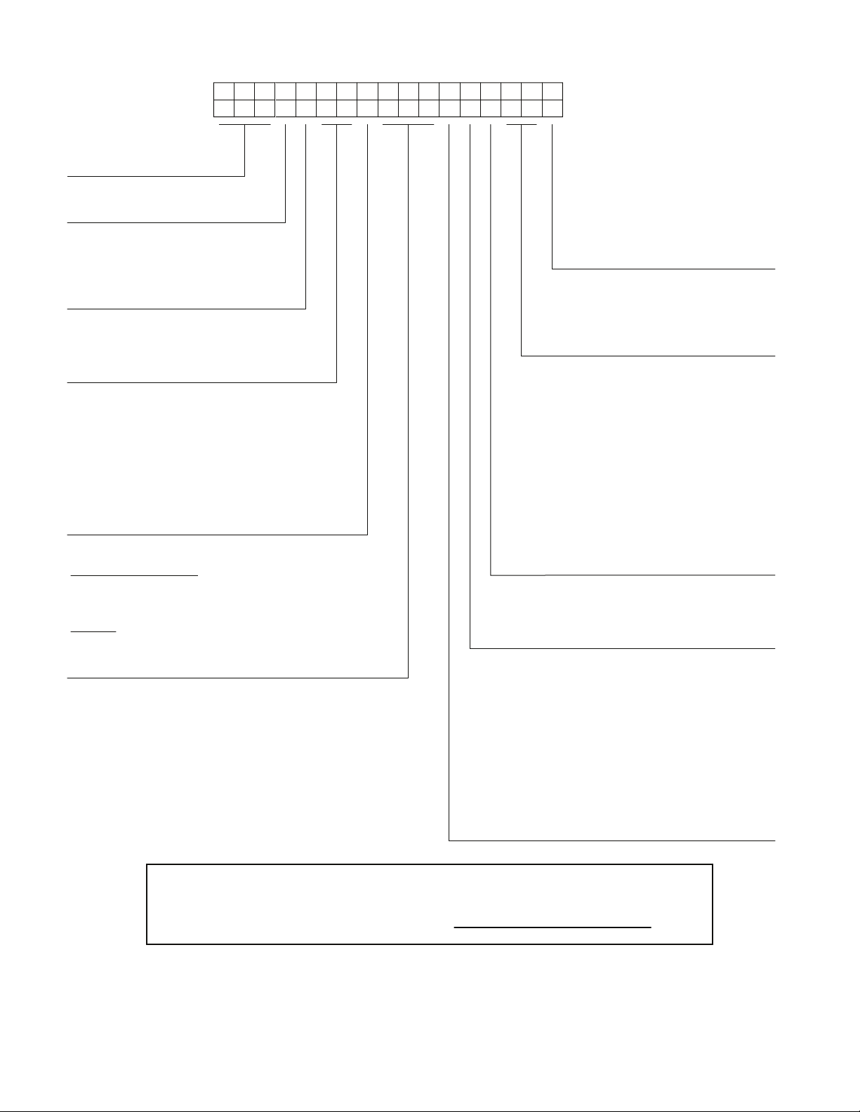
Model
J - Puron
®
(R-410A) Refrigerant
Unit Type
582 - Gas Heat RTU, Legacy Series
Packaging and Control
A = Standard Packaging, electro-mechanical
controls that require W7212 EconoMi$er® IV
B = LTL Packaging
, electro-mechanical
controls that require W7212 EconoMi$er IV
C = Standard Packaging, electro-mechanical
controls that require W7220 EconoMi$er X
F = LTL Packaging, electro-mechanical
controls that require W7220 EconoMi$er X
Cooling Tons
04 - 3 tons
05 - 4 tons
06 - 5 tons
Heat Level Input
Standard / Stainless Steel
072 = 72,000
115 = 115,000
150 = 150,000
Low NOx
060 = 60,000
090 = 90,000
120 = 120,000
Indoor Fan Options
0 = Direct Drive ECM
2 = Medium Static Option
3 = High Static Option
Refrig. System/Gas Heat Options
A = Standard One Stage cooling models/Nat. Gas Heat
B = Standard One Stage cooling models/Low NO
x
Heat
C = Standard One Stage cooling models/SS HX Heat
G = One-Stage cooling models/Alum Heat Exchanger
with Perfect Humidity™
H = One-Stage cooling models/Low NO
x
Heat
with Perfect Humidity
J = One-Stage cooling models/Stainless Steel Exchanger
with Perfect Humidity
Coil Options (RTPF) (Outdoor - Indoor - Hail Guard)
A = Al/Cu - Al/Cu
B = Precoat Al/Cu - Al/Cu
C = E-coat Al/Cu - Al/Cu
D = E-coat Al/Cu - E-coat Al/Cu
E = Cu/Cu - Al/Cu
F = Cu/Cu - Cu/Cu
M = Al/Cu -Al/Cu — Louvered Hail Guard
N = Precoat Al/Cu - Al/Cu — Louvered Hail Guard
P = E-coat Al/Cu - Al/Cu — Louvered Hail Guard
Q = E-coat Al/Cu - E-coat Al/Cu — Louvered Hail Guard
R = Cu/Cu - Al/Cu — Louvered Hail Guard
S = Cu/Cu - Cu/Cu — Louvered Hail Guard
Voltage
E = 460-3-60
J = 208/230-1-60
P = 208/230-3-60
T = 575-3-60
Outdoor Air Options
A = None
B = Temperature Economizer, Barometric Relief,
Standard Leak (W7212 or W7220)
E = Temperature Economizer, Barometric Relief,
Standard Leak w/CO
2
(W7212 or W7220)
H =
Enthalpy
Economizer, Barometric Relief,
Standard Leak (W7212 or W7220)
L =
Enthalpy
Economizer, Barometric Relief,
Standard Leak w/CO
2
(W7212 or W7220)
Q = Motorized 2 Position Damper
U = Temperature
Economizer,
Barometric
Relief,
Ultra Low Leak (W7220)
W =
Enthalpy Economizer,
Barometric
Relief, Ultra Low Leak
(W7220)
Example:
Position:
582JE06A072A0B0A
A
1234567891011 12 13 14 15 16
17
Factory Installed Options
0A = None
NOTE: See the 582J 3 to 5 ton Price Pages
for a complete list of factory installed
options.
Note: On single phase(-J) voltage code) models, the
following are not available as a factory installed option:
- Perfect Humidity
- Coated Coils or Cu Fin Coils
- Louvered Hail Guards
- Economizer or 2 Position Damper
- Powered 115 Volt Convenience Outlet
For California Residents:
For installation in SCAQMD only: This furnace does not meet the SCAQMD Rule 1111 14 ng/J
NOx emission limit, and thus is subject to a mitigation fee of up to $450. This furnace is not
eligible for the Clean Air Furnace Rebate Program: www.CleanAirFurnaceRebate.com.
MODEL NUMBER NOMENCLATURE
\
4
®
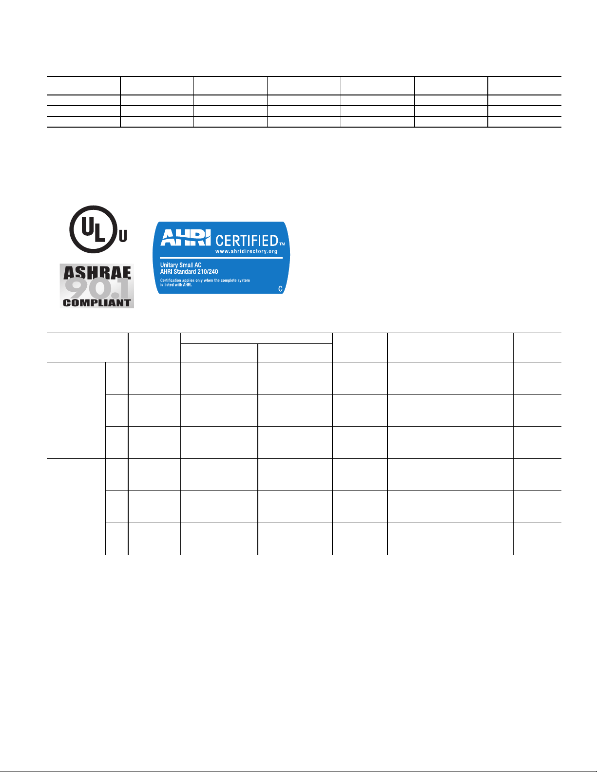
C
S
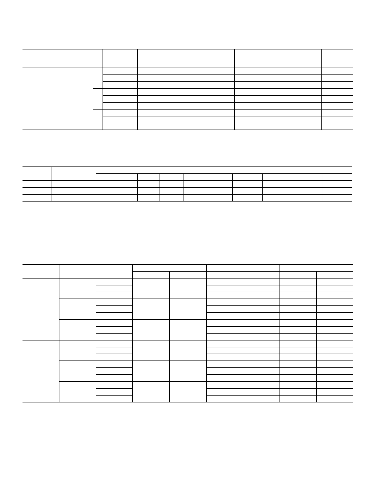
AHRI CAPACITY RATINGS
AHRI COOLING RATING TABLE
UNIT COOLING STAGES
582J*04 1 3 35.4 3.0 14.0 12.00
582J*05 1 4 47.5 4.0 14.0 12.00
582J*06 1 5 58.5 4.9 14.1 12.00
LEGEND NOTES:
AHRI — Air-Conditioning, Heating, and Refrigeration Institute Test
ASHRAE — American Society of Heating, Refrigerating, and Air-Condition-
EER — Energy Efficiency Ratio
SEER — Seasonal Energy Efficiency Ratio
Standard
ing Engineers
NOM. CAPACITY
(TONS)
NET COOLING
CAPACITY (MHBH)
1. Rated in accordance with AHRI Standard 210/240.
2. Ratings are based on:
3. All 582J units comply with ASHRAE 90.1 and Department of Energy
4. All 582J units comply with US Energy Policy Act (2005). To evaluate
TOTAL POWER
(kW)
Cooling Standard: 80°F (27°C) db, 67°F (19°C) wb indoor air temperature and 95°F (35°C) db outdoor air temperature.
(DOE) Energy Standard for minimum SEER and EER requirements.
code compliance requirements, refer to state and local codes.
SEER EER
HEATING RATING TABLE - NATURAL GAS AND PROPANE
582J UNITS GAS HEAT
LOW – 65/53 25-55 82.0% 81.0%
04
SINGLE
PHASE
THREE
PHASE
NOTES:
1. Heat ratings are for natural gas heat exchangers operated at or below
2000 ft (610 m). For information on propane or altitudes above 2000 ft
(610 m), see the Application Data section of this book. Accessory Propane/High Altitude kits are also available.
2. In the USA, the input rating for altitudes above 2000 ft (610 m) must be
de-rated by 4% for each 1000 ft (305 m) above sea level. In Canada, the
input rating must be de-rated by 10% for altitudes of 2000 ft (610) to
4500 ft (1372 m) above sea level.
05
06
04
05
06
MED – 90/73.5 45-85 82.0% 81.2%
HIGH – – – – –
LOW – 65/53 20-55 82.0% 81.0%
MED – 90/73.5 30-65 82.0% 81.2%
HIGH – 130/106 45-80 82.0% 81.0%
LOW – 65/53 15-55 82.0% 81.0%
MED – 90/73.5 25-65 82.0% 81.2%
HIGH – 130/106 35-80 82.0% 81.0%
LOW – 72/59 25-55 82.0% N/A
MED 82/66 115/93 55-85 81.0% N/A
HIGH – – – – –
LOW – 72/59 25-55 82.0% N/A
MED – 115/93 35-65 81.0% N/A
HIGH 120/96 150/120 50-80 80.0% N/A
LOW – 72/59 20-55 82.0% N/A
MED – 115/93 30-65 81.0% N/A
HIGH 120/96 150/120 40-80 80.0% N/A
AL/SS HEAT EXCHANGER
INPUT/OUTPUT
STAGE 1 (MBH)
INPUT/OUTPUT
STAGE 2 (MBH)
TEMP RISE
(DEG F)
THERMAL EFFICIENCY (%) AFUE (%)
5
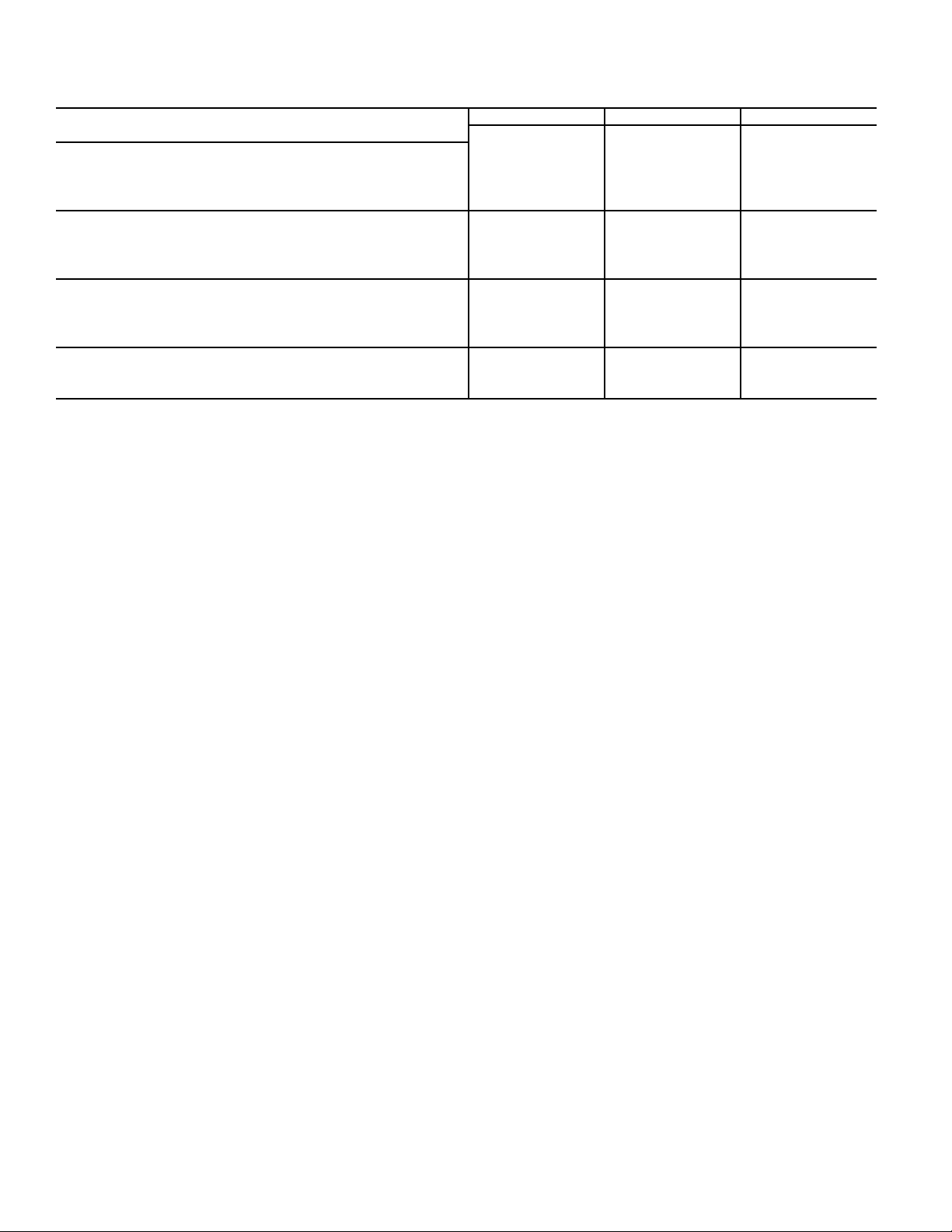
AHRI CAPACITY RATINGS (cont)
HEATING RATING TABLE – LOW NOX (see note)
582J UNIT GAS HEAT
LOW — 60/49 20–50 82.0% 81.3%
04
SINGLE/THREE PHASE
— – Not applicable. NOTE: Units meet California’s South Coast Air Quality Management District
05
06
MED — 90/73.5 30–60 82.0% 81.5%
HIGH — — — — —
LOW — 60/49 20–50 82.0% 81.3%
MED — 90/73.5 30–60 82.0% 81.5%
HIGH — 120/98 40–70 82.0% 81.3%
LOW — 60/49 15–50 82.0% 81.3%
MED — 90/73.5 25–60 82.0% 81.5%
HIGH — 120/98 35–70 82.0% 81.3%
LOW NO
INPUT/OUTPUT
STAGE 1 (MBH)
HEAT EXCHANGER
X
INPUT/OUTPUT
STAGE 2 (MBH)
(SCQAQMD) Low - NO
less.
TEMP RISE
(DEG F)
emissions requirement of 40 nanograms per joule or
X
THERMAL
EFFICIENCY (%)
AFUE (%)
SOUND PERFORMANCE TABLE
582J UNIT
04 A 1 76 78.2 78.0 74.2 73.3 70.6 66.0 62.4 56.9
05 A 1 81 90.9 84.6 79.5 77.9 76.5 71.1 66.9 62.5
06 A 1 77 87.5 82.5 76.1 73.6 71.3 67.1 64.1 60.0
LEGEND
dB – Decibel
NOTES:
1. Outdoor sound data is measured in accordance with AHRI standard 270.
2. Measurements are expressed in terms of sound power. Do not compare these
values to sound pressure values because sound pressure depends on specific
COOLING
STAGES
A–WEIGHTED 63 125 250 500 1000 2000 4000 8000
OUTDOOR SOUND (dB) AT 60 Hz
environmental factors which normally do match individual applications. Sound
power values are independent of the environment and therefore more accurate.
3. A-weighted sound ratings filter out very high and very low frequencies, to
better approximate the response of the “average” human ear. A-weighted measurement for Bryant units are taken in accordance with AHRI standard 270.
MINIMUM - MAXIMUM AIRFLOW RATINGS–NATURAL GAS AND PROPANE
VOLTAGE UNIT HEAT LEVEL
LOW
SINGLE
PHASE
THREE
PHASE
582J*04
582J*05
582J*06
582J*04
582J*05
582J*06
MED 800 1520 800 1520
HIGH ————
LOW
MED 1050 2280 1050 2280
HIGH 1230 2190 1230 2190
LOW
MED 1050 2730 1050 2730
HIGH 1230 2820 1230 2820
LOW
MED 1010 1570 1010 1570
HIGH ————
LOW
MED 1330 2460 1330 2460
HIGH 1390 2220 1390 2220
LOW
MED 1330 2880 1330 2880
HIGH 1390 2780 1390 2780
COOLING AL HX HEATING SS HX HEATING
MINIMUM MAXIMUM MINIMUM MAXIMUM MINIMUM MAXIMUM
900 1970 900 1970
900 1500
900 2470 900 2470
1200 2000
900 3290 900 3290
1500 2500
990 2190 990 2190
900 1500
990 2190 990 2190
1200 2000
990 2730 990 2730
1500 2500
6

PHYSICAL DATA
REFERIGERATION SYSTEM
®
Puron
®
Puron
Perfect Humidity™ Puron
EVAPORATION COIL
PERFECT HUMIDITY COIL
EVAP. FAN AND MOTOR
STANDARD STATIC
1 PHASE
MEDIUM STATIC
1 PHASE
HIGH STATIC
1 PHASE
STANDARD STATIC
3 PHASE
MEDIUM STATIC
3 PHASE
HIGH STATIC
3 PHASE
PHYSICAL DATA (COOLING) 3-5 TONS
582J*04A/B 582J*05A/B 582J*06A/B
# Circuits / # Comp. / Type 1 / 1 / Scroll 1 / 1 / Scroll 1 / 1 / Scroll
refrig. (R-410A) A 1 phase (lbs-oz) 7-2 10-8 16-0
refrig. (R-410A) A 3 phase (lbs-oz) 7-2 10-8 14-8
®
refrig. (R-410A) charge A (lbs-oz) 10-6 15-5 26-0
oil A/B (oz) 25 42 42
Metering Device Acutrol Acutrol Acutrol
Perfect Humidity Metering Device Acutrol + TXV Acutrol + TXV Acutrol + TXV
High-press. Trip / Reset (psig) 630/505 630/505 630/505
Low-press. Trip / Reset (psig) 54/117 54/117 54/117
Loss of charge Trip/Reset (psig) N/A N/A N/A
Material (Tube/Fin) Cu/Al Cu/Al Cu/Al
Coil Type
Rows / FPI 3 / 15 3 / 15 4 / 15
Total Face Area (ft
Condensate Drain Conn. Size
Material (Tube/Fin) Cu/Al Cu/Al Cu/Al
Coil Type
Rows / FPI 1 / 17 2 / 17 2 / 17
Total Face Area (ft
Motor Qty / Drive Type 1 / Direct 1 / Direct 1 / Direct
Max BHP111
RPM Range 600-1200 600-1200 600-1200
Motor Frame Size 48 48 48
Fan Qty / Type 1 / Centrifugal 1 / Centrifugal 1 / Centrifugal
Fan Diameter (in.) 10 x 10 10 x 10 10 x 10
Motor Qty / Drive Type 1 / Belt 1 / Belt 1 / Belt
Max BHP 1.2 1.2 1.5
RPM Range 770-1175 770-1175 1035-1466
Motor Frame Size 48 48 56
Fan Qty / Type 1 / Centrifugal 1 / Centrifugal 1 / Centrifugal
Fan Diameter (in.) 10 x 10 10 x 10 10 x 10
Motor Qty / Drive Type 1 / Belt 1 / Belt N/A
Max BHP 1.5 1.5 N/A
RPM Range 1035-1466 1035-1466 N/A
Motor Frame Size 56 56 N/A
Fan Qty / Type 1 / Centrifugal 1 / Centrifugal N/A
Fan Diameter (in.) 10 x 10 10 x 10 N/A
Motor Qty / Drive Type 1 / Direct 1 / Direct 1 / Direct
Max BHP111
RPM Range 600-1200 600-1200 600-1200
Motor Frame Size 48 48 48
Fan Qty / Type 1 / Centrifugal 1 / Centrifugal 1 / Centrifugal
Fan Diameter (in.) 10 x 10 10 x 10 11 x 10
Motor Qty / Drive Type 1 / Belt 1 / Belt 1 / Belt
Max BHP 1.7 1.7 2.9
RPM Range 770-1175 920-1303 1035-1466
Motor Frame Size 48 56 56
Fan Qty / Type 1 / Centrifugal 1 / Centrifugal 1 / Centrifugal
Fan Diameter (in.) 10 x 10 10 x 10 10 x 10
Motor Qty / Drive Type 1 / Belt 1 / Belt 1 / Belt
Max BHP 2.9 2.9 2.9
RPM Range 1035-1466 1208-1550 1303-1550
Motor Frame Size 56 56 56
Fan Qty / Type 1 / Centrifugal 1 / Centrifugal 1 / Centrifugal
Fan Diameter (in.) 10 x 10 10 x 10 10 x 10
3
/8-in. RTPF
2
) 5.5 5.5 7.3
2
) 3.9 3.9 5.2
3
/4-in.
3
/8-in. RTPF
3
/8-in. RTPF
3
/4-in.
3
/8-in. RTPF
3
/8-in. RTPF
3
3
/8-in. RTPF
/4-in.
7
PHYSICAL DATA (CONT)
PHYSICAL DATA (COOLING) 3-5 TONS (cont)
582J*04A/B 582J*05A/B 582J*06A/B
COND. COIL
1 phase Material (Tube/Fin) Cu/Al Cu/Al Cu/Al
Coil Type
Rows / FPI 1 / 17 2 / 17 2 / 17
Total Face Area (ft
2
3 phase Material (Tube/Fin)
Coil Type
Rows / FPI 1/17 2/17 2/17
Total Face Area (ft
2
COND. FAN / MOTOR
Qty / Motor Drive Type 1 / Direct 1 / Direct 1 / Direct
Motor HP / RPM 1 / 8 / 825 1 / 4 / 1100 1 / 4 / 1100
Fan diameter (in.) 22 22 22
FILTERS
RA Filter # / Size (in.) 2 / 16 x 25 x 2 2 / 16 x 25 x 2 4 / 16 x 16 x 2
OA inlet screen # / Size (in.) 1 / 20 x 24 x 1 1 / 20 x 24 x 1 1 / 20 x 24 x 1
N/A – Not applicable
3
/8-in. RTPF
3
/8-in. RTPF
3
/8-in. RTPF
) 16.5 16.5 21.3
3
/8-in. RTPF
3
/8-in. RTPF
3
/8-in. RTPF
) 16.5 14.6 18.8
8

PHYSICAL DATA (HEATING - SINGLE PHASE UNITS) 3-5 TONS
ELECTRICAL
GAS CONNECTION
Nat. gas supply line pressure (in. wg) / (PSIG) 4-13 / 0.18-0.47 4-13 / 0.18-0.47 4-13 / 0.18-0.47
LP gas supply line pressure (in. wg) / (PSIG) 11-13 / 0.40-0.47 11-13 / 0.40-0.47 11-13 / 0.40-0.47
HEAT ANTICIPATOR SETTING (AMPS)
NATURAL GAS HEAT
# of stages / # of burners (total) 1 / 2 1 / 2 1 / 2
LOW
MED
HIGH
LIQUID PROPANE HEAT
LOW
MED
HIGH
LOW NOX GAS HEAT
LOW
MED
HIGH
LEGEND
LP – Liquid propane
— – Not applicable
Rollout switch opens/closes (°F) 195 / 115 195 / 115 195 / 115
# of stages / # of burners (total) 1 or 2 / 3 1 / 3 1 / 3
Rollout switch opens/closes (°F) 195 / 115 195 / 115 195 / 115
# of stages / # of burners (total) — 1 or 2 / 3 1 or 2 / 3
Rollout switch opens/closes (°F) — 195 / 115 195 / 115
# of stages / # of burners (total) 1 / 2 1 / 2 1 / 2
Rollout switch opens/closes (°F) 195 / 115 195 / 115 195 / 115
# of stages / # of burners (total) 1 / 3 1 / 3 1 / 3
Rollout switch opens/closes (°F) 195 / 115 195 / 115 195 / 115
# of stages / # of burners (total) — 1 / 3 1 / 3
Rollout switch opens/closes (°F) — 195 / 115 195 / 115
582J*04 582J*05 582J*06
Single Phase Single Phase Single Phase
# of Gas valves 1 1 1
First stage 0.14 0.14 0.14
Second stage 0.14 0.14 0.14
Connection size
1
/2-in. NPT
1
/2-in. NPT
1
/2-in. NPT
Temperature rise (°F) 25-55 20-55 15-55
Connection size
1
/2-in. NPT
1
/2-in. NPT
1
/2-in. NPT
Temperature rise (°F) 45-85 30-65 25-65
Connection size —
1
/2-in. NPT
1
/2-in. NPT
Temperature rise (°F) — 45-80 35-80
Connection size
1
/2-in. NPT
1
/2-in. NPT
1
/2-in. NPT
Temperature rise (°F) 25-55 20-55 15-55
Connection Size
1
/2-in. NPT
1
/2-in. NPT
1
/2-in. NPT
Temperature Rise (°F) 45-85 30-65 25-65
Connection size —
1
/2-in. NPT
1
/2-in. NPT
Temperature rise (°F) — 45-80 35-80
Connection size
1
/2-in. NPT
1
/2-in. NPT
1
/2-in. NPT
Temperature rise (°F) 20-50 20-50 15-50
Connection size
1
/2-in. NPT
1
/2-in. NPT
1
/2-in. NPT
Temperature rise (°F) 30-60 30-60 25-60
Connection size —
1
/2-in. NPT
1
/2-in. NPT
Temperature rise (°F) — 40-70 35-70
9

PHYSICAL DATA (CONT)
PHYSICAL DATA (HEATING - THREE PHASE UNITS) 3-5 TONS
ELECTRICAL
GAS CONNECTION
# of Gas valves 1 1 1
Nat. gas supply line pressure (in. wg.) / (PSIG) 4-13 / 0.18-0.47 4-13 / 0.18-0.47 4-13 / 0.18-0.47
LP gas supply line pressure (in. wg.) / (PSIG) 11-13 / 0.40-0.47 11-13 / 0.40-0.47 11-13 / 0.40-0.47
HEAT ANTICIPATOR SETTING (AMPS)
First stage 0.14 0.14 0.14
Second stage 0.14 0.14 0.14
NATURAL GAS HEAT
# of stages / # of burners (total) 1 / 2 1 / 2 1 / 2
LOW
MED
HIGH
LIQUID PROPANE HEAT
LOW
MED
HIGH
LOW NOX GAS HEAT
LOW
MED
HIGH
LEGEND
LP – Liquid propane
— – Not applicable
Rollout switch opens/closes (°F) 195 / 115 195 / 115 195 / 115
# of stages / # of burners (total) 1 or 2 / 3 1 / 3 1 / 3
Rollout switch opens/closes (°F) 195 / 115 195 / 115 195 / 115
# of stages / # of burners (total) — 1 or 2 / 3 1 or 2 / 3
Rollout switch opens/closes (°F) — 195 / 115 195 / 115
# of stages / # of burners (total) 1 / 2 1 / 2 1 / 2
Rollout switch opens/closes (°F) 195 / 115 195 / 115 195 / 115
# of stages / # of burners (total) 1 or 2 / 3 1 / 3 1 / 3
Rollout switch opens/closes (°F) 195 / 115 195 / 115 195 / 115
# of stages / # of burners (total) — 1 or 2 / 3 1 or 2 / 3
Rollout switch opens/closes (°F) — 195 / 115 195 / 115
# of stages / # of burners (total) 1 / 2 1 / 2 1 / 2
Rollout switch opens/closes (°F) 195 / 115 195 / 115 195 / 115
# of stages / # of burners (total) 1 / 3 1 / 3 1 / 3
Rollout switch opens/closes (°F) 195 / 115 195 / 115 195 / 115
# of stages / # of burners (total) — 1 / 3 1 / 3
Rollout switch opens/closes (°F) — 195 / 115 195 / 115
Connection size
Temperature rise (°F) 25-55 25-55 20-55
Connection size
Temperature rise (°F) 55-85 35-65 30-65
Connection size —
Temperature rise (°F) — 50-80 40-80
Connection size
Temperature rise (°F) 25-55 25-55 20-55
Connection size
Temperature rise (°F) 55-85 35-65 30-65
Connection size —
Temperature rise (°F) — 50-80 40-80
Connection size
Temperature rise (°F) 20-50 20-50 15-50
Connection size
Temperature rise (°F) 30-60 30-60 25-60
Connection size —
Temperature rise (°F) — 40-70 35-70
582J*04 582J*05 582J*06
Three Phase Three Phase Three Phase
1
/2-in. NPT
1
/2-in. NPT
1
/2-in. NPT
1
/2-in. NPT
1
/2-in. NPT
1
/2-in. NPT
1
/2-in. NPT
1
/2-in. NPT
1
/2-in. NPT
1
/2-in. NPT
1
/2-in. NPT
1
/2-in. NPT
1
/2-in. NPT
1
/2-in. NPT
1
/2-in. NPT
1
/2-in. NPT
1
/2-in. NPT
1
/2-in. NPT
1
/2-in. NPT
1
/2-in. NPT
1
/2-in. NPT
1
/2-in. NPT
1
/2-in. NPT
1
/2-in. NPT
10
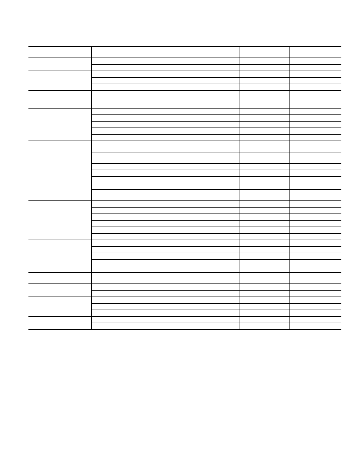
OPTIONS AND ACCESSORIES
CATEGORY ITEM
CABINET
COIL OPTIONS
Thru-the-base electrical or gas-line connections X X
Hinged Access Panels X
Cu/Cu indoor and/or outdoor coils
Pre-coated outdoor coils
Premium, E-coated outdoor coils
5
5
5
HUMIDITY CONTROL Perfect Humidity™ Dehumidification System
CONDENSER
PROTECTION
Condenser coil hail guard (louvered design)
5
5
FACTORY-
INSTALLED OPTION
X
X
X
X
XX
Thermostats, temperature sensors, and subbases X
RTU Open multi-protocol controller X
CONTROLS
Smoke detector (supply and/or return air) X
Time Guard II compressor delay control circuit X
Phase Monitor X
ECONOMIZERS AND
OUTDOOR AIR DAMPERS
EconoMi$er IV for electro-mechnical controls - Non FDD (Standard
air leak damper models)
EconoMi$er2 for DDC controls, complies with FDD (Standard and
Ultra Low Leak air damper models)
Motorized 2-position outdoor air damper
5, 6
5, 7
5
Manual outdoor air damper (25% and 50%) X
Barometric relief
1
XX
XX
XX
XX
Power exhaust X
ECONOMIZER SENSORS
AND IAQ DEVICES
EconoMi$er X for electro-mechanical controls, complies with FDD.
(Standard and Ultra Low Leak air damper models)
Single dry bulb temperature sensors
Differential dry bulb temperature sensors
sensor
2
2
2
sensor
2
2
Single enthalpy sensors
Differential enthalpy sensors
Wall-mounted or duct-mounted CO
Unit-mounted CO
5, 6
2
2
2
XX
XX
XX
X
Propane conversion kit X
Stainless steel heat exchanger X
GAS HEAT
High altitude conversion kit X
Flue Shield X
Flue Discharge Deflector X
INDOOR MOTOR AND
DRIVE
LOW AMBIENT CONTROL
POWER OPTIONS
ROOF CURBS
Multiple motor and drive packages X
Winter start kit
Motormaster
®
head pressure controller
Convenience outlet (powered)
3
3
5
X
Convenience outlet (non-powered) X
Non-fused disconnect
4
X
Roof curb 14-in. (356mm) X
Roof curb 24-in. (610mm) X
NOTES:
1. Included with economizer.
2. Sensors used to optimize economizer performance.
3. See application data for assistance.
4. Available on units with MOCPs of 80 amps or less.
5. Not available as factory-installed option on single phase (208-230/1/60) models. Use field-installed accessory where available.
6. FDD (Fault Detection and Diagnostic) capability per California Title 24 section 120.2.
7. Models with RTU Open DDC controls comply with California Title 24 Fault Detection and Diagnostic (FDD).
FIELD-INSTALLED
ACCESSORY
X
X
X
X
X
11

OPTIONS AND ACCESSORIES (CONT)
Economizer
Economizers save energy, money and improve comfort levels
in the conditioned space. They bring in fresh, outside air for
ventilation; and provide cool outside air to cool your building.
This is also the preferred method of low ambient cooling.
When integrated with CO
sensors, economizers can provide
2
even more savings by coupling the ventilation air to only the
amount required based on space occupancy. Economizers are
available, installed and tested by the factory, with either
enthalpy or temperature dry-bulb inputs. There are also models
for electromechanical and direct digital controllers. Additional
sensors are available as accessories to optimize the economizer.
Economizers include gravity controlled barometric relief that
helps equalize building pressure and ambient air pressures.
This can be a cost effective solution to prevent building pressurization. Economizers are available in Ultra Low Leak and
standard low leak versions.
CO2 sensor
CO2 sensors improve productivity and save money by working
with the economizer to intake the correct amount of outside air
for ventilation. As occupants fill your building, the CO
detects their presence through increasing CO
levels and opens
2
sensor
2
the economizer appropriately.
When the occupants leave, the CO
levels decrease, and the
2
sensor appropriately closes the economizer. This intelligent
control of the ventilation air, called Demand Controlled Ventilation (DCV) reduces the overall load on the rooftop, saving
money.
Smoke detectors
Trust the experts. Smoke detectors make your application safer
and your job easier. Bryant smoke detectors immediately shut
down the rooftop unit when smoke is detected. They are available, installed by the factory, for supply air, return air, or both.
Louvered hail guards
Sleek, louvered panels protect the condenser coil from hail
damage, foreign objects, and incidental contact.
Convenience outlet (powered or un-powered)
Reduce service and/or installation costs by including a convenience outlet in your specification. Bryant will install this service feature at our factory. It provides a convenient, 15 amp,
115v GFCI receptacle with “Wet in Use” cover. The “powered”
option allows the installer to power the outlet from the line side
of the disconnect or load side as required by code. The “unpowered” option is to be powered from a separate 115/120-v
power source.
Non-fused disconnect
This OSHA-compliant, factory-installed safety switch allows a
service technician to locally secure power to the rooftop.
Power exhaust with barometric relief
Superior internal building pressure control. This field-installed
accessory may eliminate the need for costly, external pressure
control fans.
RTU Open, multi-protocol controller
Connect the rooftop to an existing BAS without needing complicated translators or adapter modules using the RTU Open
controller. This new controller speaks the 4 most common
building automation system languages (BACnet
N2, and LonWorks
3
). Use this controller when you have an
1
, Modbus2,
existing BAS.
Time Guard II control circuit
This accessory protects your compressor by preventing shortcycling in the event of some other failure and prevents the compressor from restarting for 30 seconds after stopping. Not
required with RTU Open or authorized commercial thermostats.
Motorized 2-position damper
The new Bryant 2-position, motorized outdoor air damper
admits up to 100% outside air. Using reliable, gear-driven technology, the 2-position damper opens to allow ventilation air and
closes when the rooftop stops, stopping unwanted infiltration.
Manual OA damper
Manual outdoor air dampers are an economical way to bring in
ventilation air. The dampers are available in 25% and 50%
versions.
Optional Perfect Humidity™ dehumidification system
Bryant’s Perfect Humidity dehumidification system is an allinclusive factory-installed option that can be ordered with any
Legacy Line 582J*04-06B rooftop unit.
This system expands the envelope of operation of Bryant’s
Legacy Line rooftop products to provide unprecedented flexibility to meet year-round comfort conditions.
The Perfect Humidity dehumidification system has the industry’s only dual dehumidification mode setting. The Perfect
Humidity system includes two new modes of operation.
The Legacy Line 582J*04-06B rooftop coupled with the Perfect Humidity system is capable of operating in normal design
cooling mode, subcooling mode, and hot gas reheat mode. Normal design cooling mode is when the unit will operate under its
normal sequence of operation by cycling compressors to maintain comfort conditions.
Subcooling mode will operate to satisfy part load type conditions when the space requires combined sensible and a higher
proportion of latent load control. Hot Gas Reheat mode will
operate when outdoor temperatures diminish and the need for
latent capacity is required for sole humidity control. Hot Gas
Reheat mode will provide neutral air for maximum dehumidification operation.
Motormaster® head pressure controller
The Motormaster motor controller is a low ambient, head pressure
controller kit that is designed to maintain the unit’s condenser head
pressure during periods of low ambient cooling operation. This
device should be used as an alternative to economizer free cooling
when economizer usage is either not appropriate or desired. The
Motormaster will either cycle the outdoor fan motors or operate
them at reduced speed to maintain the unit operation, depending
on the model.
12
1. BACnet is a registered trademark of ASHRAE (American Society of
Heating, Refrigerating, and Air-Conditioning Engineers).
2. Modbus is a registered trademark of Schneider Electric.
3. LonWorks is a registered trademark of Echelon Corporation.

Winter start kit
The winter start kit by Bryant extends the low ambient limit of
your rooftop to 25°F (–4°C). The kit bypasses the low pressure
switch, preventing nuisance tripping of the low pressure
switch. Other low ambient precautions may still be prudent.
Propane heating
Convert your gas heat rooftop from standard natural gas operation to propane using this field-installed kit.
High altitude heating
High altitudes have less oxygen, which means heat exchangers
need less fuel. The new gas orifices in this field-installed kit
make the necessary adjustment for high altitude applications.
They restore the optimal fuel to air mixture and maintain
healthy combustion at altitudes above 2000 ft (610m). Kits
may not be required in all areas.
Hinged access panels
Allows access to unit’s major components with specifically
designed hinged access panels. Panels are: filter, control box,
fan motor, and compressor.
Flue discharge deflector
The flue discharge deflector is a useful accessory when flue gas
recirculation is a concern. By venting the flue discharge
upwards, the deflector minimizes the chance for a neighboring
unit to intake the flue exhaust.
Optional stainless steel heat exchanger
The stainless steel heat exchanger option provides the tubular
heat exchanger made out of a minimum 20 gage type 409 stainless steel for applications where the mixed air to the heat
exchanger is expected to drop below 45°F (7°C). Stainless steel
may be specified on applications where the presence of airborne contaminants require its use (applications such as paper
mills) or in areas with very high outdoor humidity that may
result in severe condensation in the heat exchanger during cooling operation.
Flue discharge heat shield
The flue discharge heat shield keeps people from touching the
rooftop unit’s potentially hot flue discharge. This is especially
useful for ground level applications, where more untrained
people could have access to the unit’s exterior.
Alternate motors and drives
Some applications need larger horsepower motors, some need
more airflow, and some need both. Regardless of the case, your
Bryant expert has a factory-installed combination to meet your
application. A wide selection of motors and pulleys (drives) are
available, factory installed, to handle nearly any application.
Thru-the-base connections
Thru-the-base connections, available as either an accessory or
as a factory option, are necessary to ensure proper connection
and seal when routing wire and piping through the rooftop’s
basepan and curb. These couplings eliminate roof penetration
and should be considered for gas lines, main power lines, as
well as control power.
13
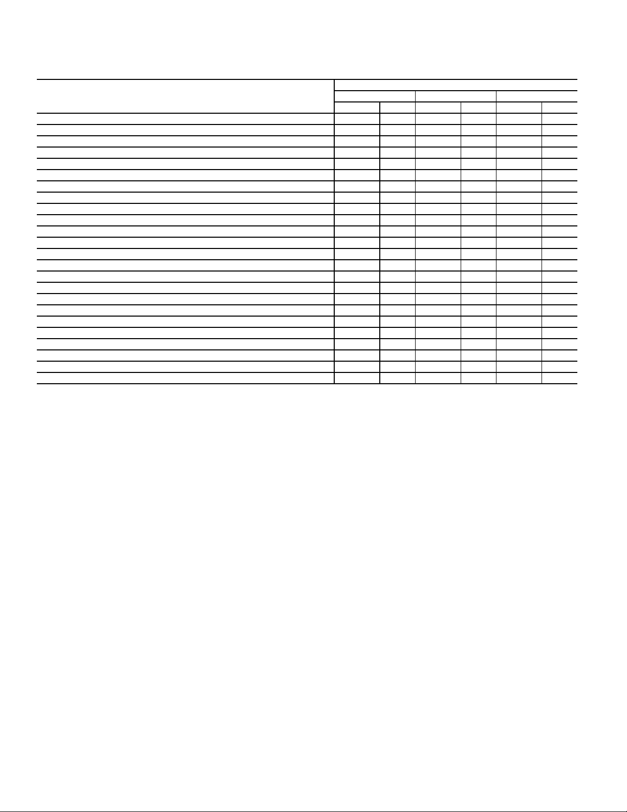
OPTIONS AND ACCESSORIES (CONT)
OPTIONS AND ACCESSORY WEIGHTS
OPTION/ACESSORY WEIGHTS
OPTION/ACCESSORY
Perfect Humidity™
1
Power exhaust - vertical 45 20 45 20 45 20
Power exhaust - horizontal 30 14 30 14 30 14
EconoMi$er (IV, X, or 2) 35 16 35 16 35 16
Two-position damper 39 18 39 18 39 18
Manual dampers 12 5 12 5 12 5
Medium gas heat 12 59494
High gas heat ——178178
Hail guard (louvered) 13 6 13 6 17 8
Cu/Cu Condenser Coil
Cu/Cu Condenser and Evaporator Coils
2
2
Roof curb (14-in. curb) 115 52 115 52 115 52
Roof curb (24-in. curb) 197 89 197 89 197 89
CO
sensor 212121
2
Flue discharge deflector 737373
Optional indoor motor/drive 6 3 6 3 17 8
Motormaster controller 949494
Return smoke detector 737373
Supply smoke detector 7 37373
Non-fused disconnect 5 25252
Powered convenience outlet 36 16 36 16 36 16
Non-powered convenience outlet 424242
Enthalpy sensor 212121
Differential enthalpy sensor 313131
NOTE: Where multiple variations are available, the heaviest combination is listed.
— Not available
1
For Perfect Humidity, add Motormaster® Controller.
2
Where available.
04 05 06
lb kg lb kg lb kg
50 23 50 23 55 25
37 17 74 34 95 43
75 34 112 51 165 75
14
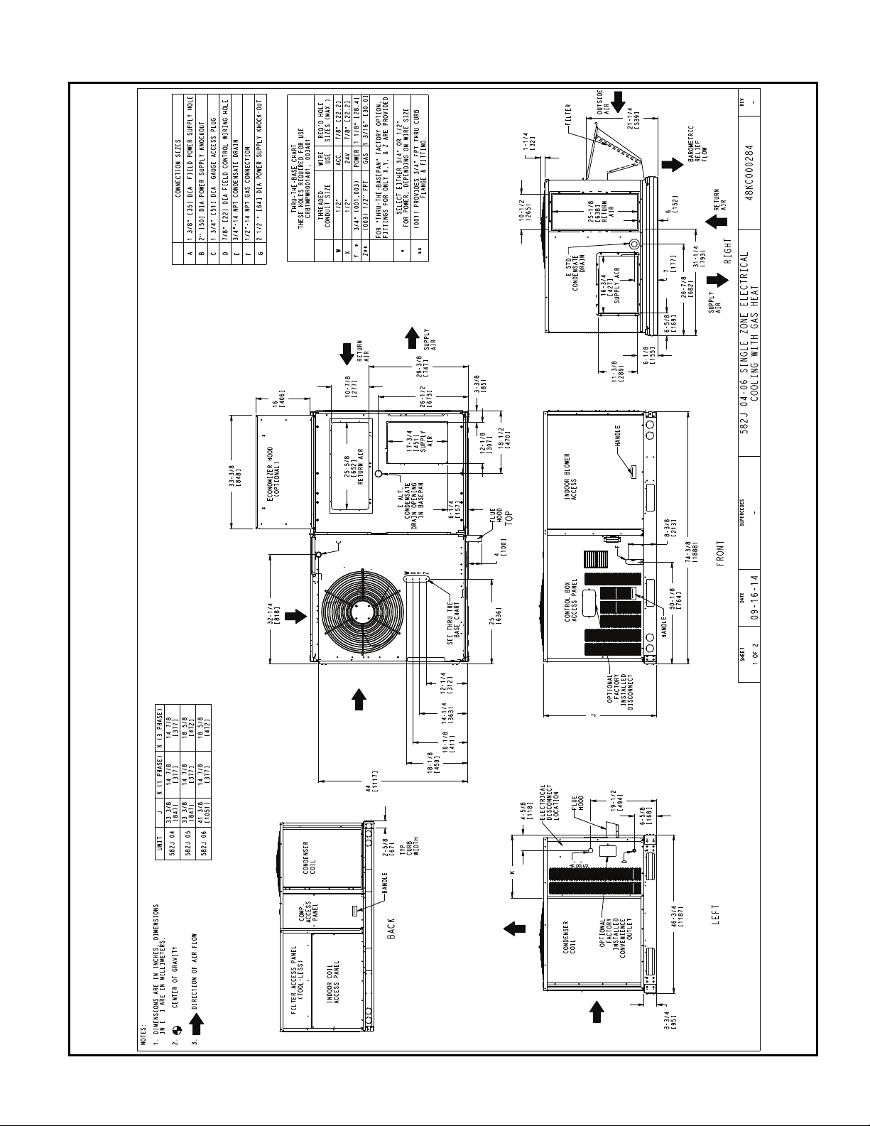
582J*04-06 BASE UNIT DIMENSIONS
BASE UNIT DIMENSIONS
15
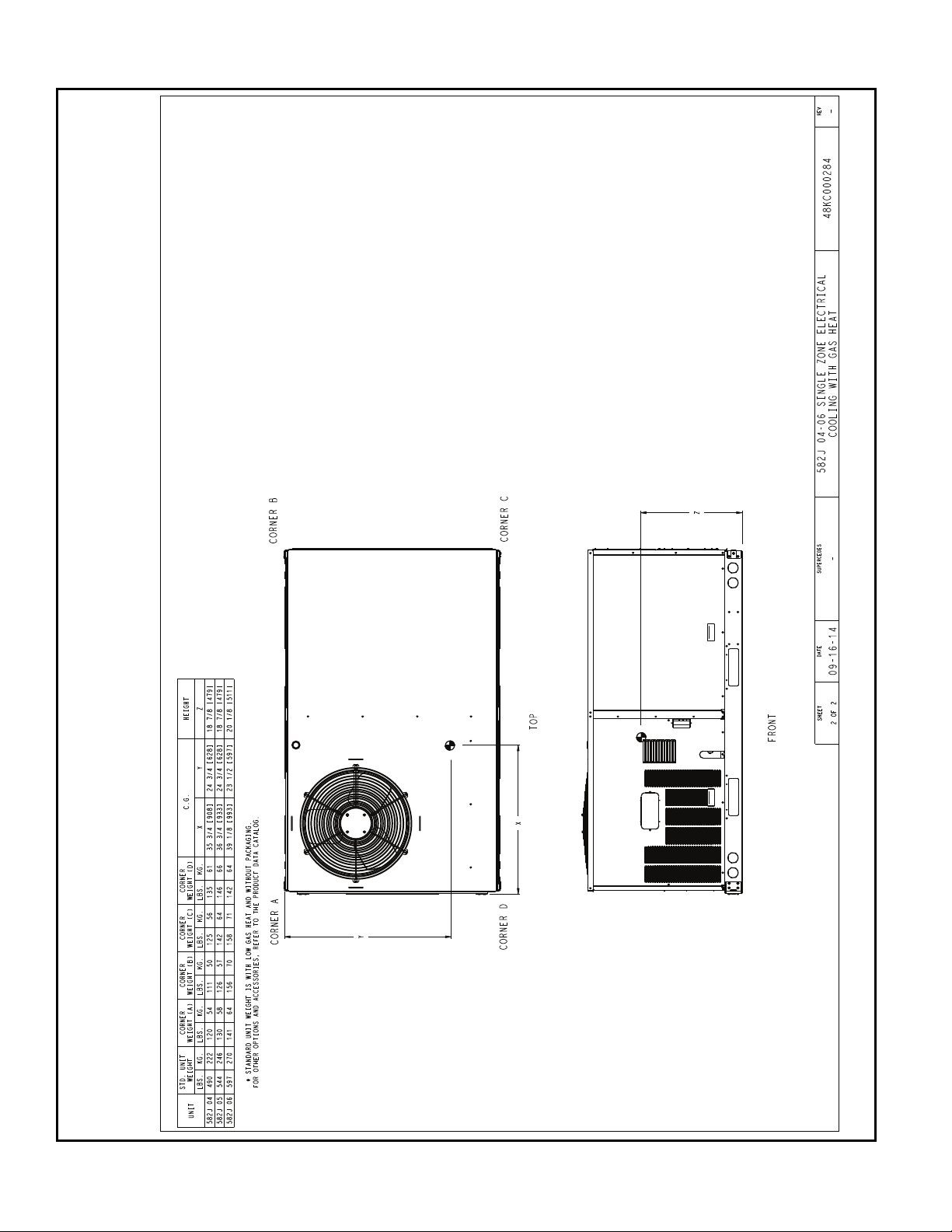
582J*04-06 CORNER WEIGHTS
BASE UNIT DIMENSIONS (CONT)
16
C
B
A
D
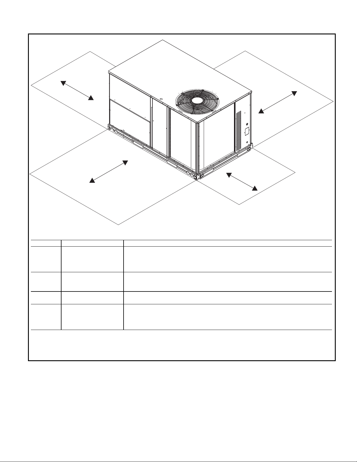
NOTE: Unit not designed to have overhead obstruction. Contact Application Engineering for guidance on any application planning overhead obstruction or for vertical clearances.
SERVICE CLEARANCE DIMENSIONS
LOCATION DIMENSION CONDITION
A
48-in. (1219 mm) Unit disconnect is mounted on panel
18-in. (457 mm) No disconnect, convenience outlet option
18-in. (457 mm) Recommended service clearance
12-in. (305 mm) Minimum clearance
B
42-in. (1067 mm) Surface behind servicer is grounded (e.g., metal, masonry wall)
36-in. (914 mm) Surface behind servicer is electrically non-conductive (e.g., wood, fiberglass)
Special Check sources of flue products within 10 ft (3 m) of unit fresh air intake hood
C
36-in. (914 mm) Side condensate drain is used
18-in. (457 mm) Minimum clearance
D
48-in. (1219 mm) No flue discharge accessory installed, surface is combustible material
42-in. (1067 mm) Surface behind servicer is grounded (e.g., metal, masonry wall, another unit)
36-in. (914 mm) Surface behind servicer is electrically non-conductive (e.g., wood, fiberglass)
Special Check for adjacent units or building fresh air intakes within 10 ft (3 m) of this unit’s flue outlet
17
 Loading...