

Bryant 582A024040, 582A036060, 582A024060, 582A036090, 582A042060 Installation, Start-up And Service Instructions Manual
...
CONTENTS
Page
SAFETY CONSIDERATIONS ........................1
GENERAL ......................................1-3
RECEIVING AND INSTALLATION .................4-14
I. Step 1 — Check Equipment ..................4
II. Step 2 — Provide Unit Support ...............4
III. Step 3 — Field Fabricate Ductwork ............4
IV. Step 4 — Provide Clearances .................4
V. Step 5 — Rig and Place Unit .................4
VI. Step 6 — Connect Condensate Drain ..........7
VII. Step 7 — Install Flue Hood ...................7
VIII. Step 8 — Install Gas Piping ..................7
IX. Step 9 — Install Duct Connections ...........10
X. Step 10 — Install Electrical Connections ......11
PRE-START-UP ................................14,15
START-UP ....................................15-29
I. Check for Refrigerant Leaks .................15
II. Start Up Heating Section and
Make Adjustments .........................15
III. Start Up Cooling Section and
Make Adjustments .........................18
MAINTENANCE ................................29-32
I. Air Filter ..................................30
II. Evaporator Blower and Motor ................30
III. Flue Gas Passageways .....................30
IV. Combustion-Air Blower .....................30
V. Limit Switch ..............................30
VI. Burner Ignition ............................31
VII. Main Burners .............................31
VIII. Condenser Coil, Evaporator Coil, and
Condenser Drain Pan .......................31
IX. Condenser Fan ............................32
X. Electrical Controls and Wiring ...............32
XI. Refrigerant Circuit .........................32
XII. Gas Input .................................32
XIII. Evaporator Airflow .........................32
XIV. Metering Device — Acutrol™ Device ..........32
XV. Liquid Line Strainer ........................32
TROUBLESHOOTING ...........................33-35
START-UP CHECKLIST ..........................CL-1
NOTE TO INST ALLER — Before the installation, READ THESE
INSTRUCTIONS CAREFULLY AND COMPLETELY. Also,
make sure the User’s Manual and Replacement Guide are
left with the unit after installation. The furnace is NOT to be
used for temporary heating of buildings or structures under
construction.
SAFETY CONSIDERATIONS
Installation and servicing of air-conditioning equipment can
be hazardous due to system pressure and electrical components. Only trained and qualified personnel should install,
repair, or service air-conditioning equipment.
Untrained personnel can perform basic maintenance functions of cleaning coils and filters. All other operations should
be performed by trained service personnel. When working on
air-conditioning equipment, observe precautions in the literature, tags and labels attached to the unit, and other safety
precautions that may apply.
Follow all safety codes. Wear safety glasses and work gloves.
Use quenching cloth for unbrazing operations. Have fire extinguisher available for all brazing operations.
WARNING:
Improper installation, adjustment, alteration, service, maintenance, or use can cause carbon monoxide poisoning, fire, or an explosion which can result
in personal injury or unit damage. Consult a qualified
installer, service agency, or gas supplier for information or assistance. The qualified installer or agency must
use only factory-authorized kits or accessories when modifying this product.
WARNING:
Before performing service or maintenance operations on unit, turn off gas supply then unit
main power switch. Electrical shock could cause personal injury.
GENERAL
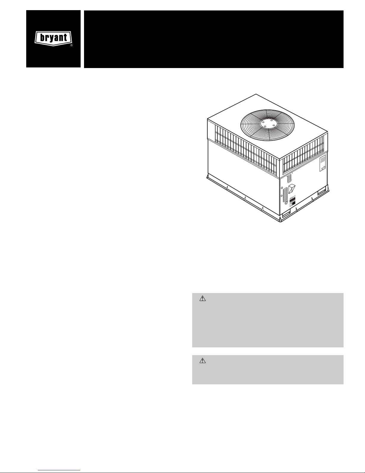
The 582A and 583A units (see Fig. 1) are fully self-contained,
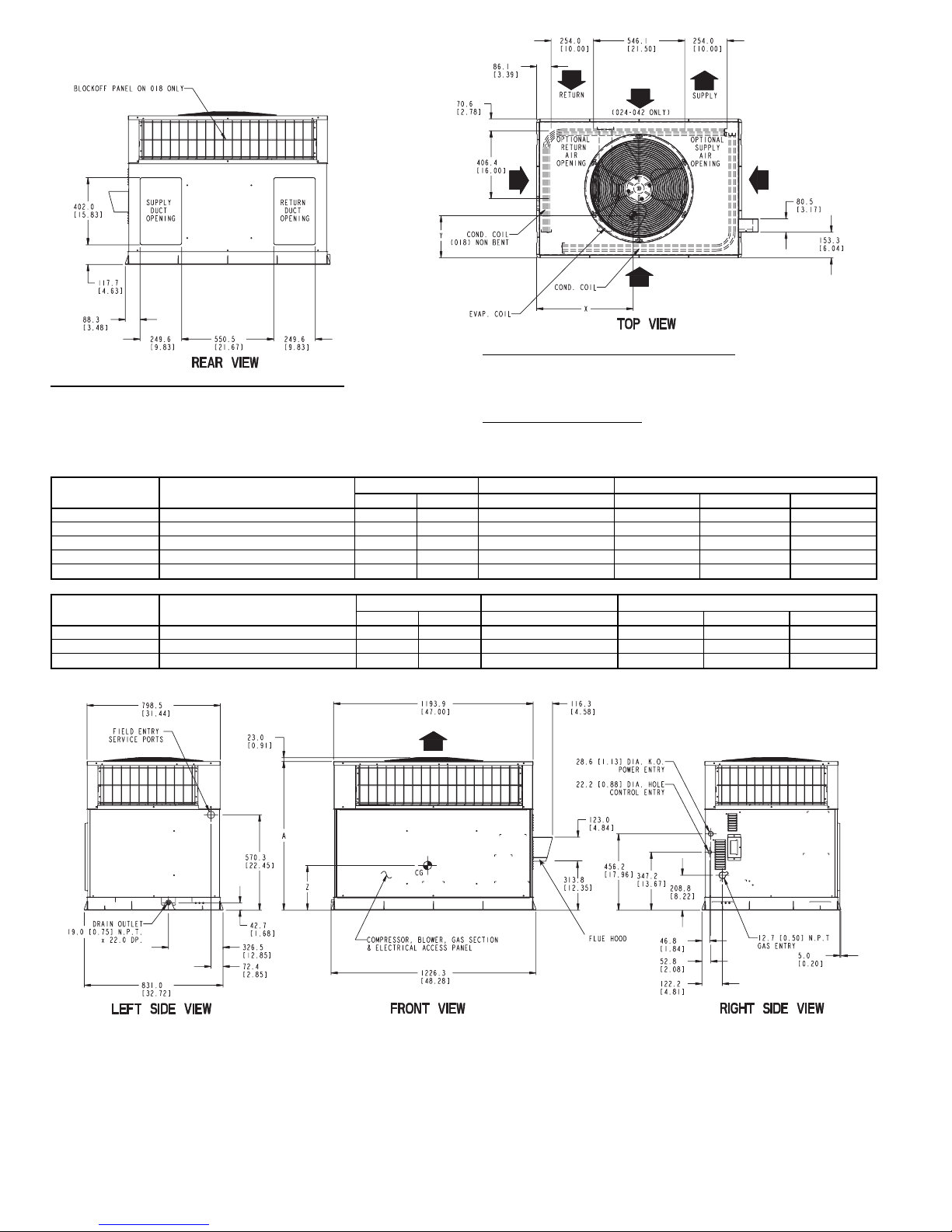
combination Category I gas heating/electric cooling units designed for outdoor installation. See Fig. 2 and 3 (pages 2,3)
for unit dimensions. All unit sizes have return and discharge
openings for both horizontal and downflow configurations, and
are factory shipped with all downflow duct openings covered.
Units may be installed on a rooftop, a cement slab, or directly on the ground (if permitted by local codes). See Fig. 4
for roof curb dimensions.
Fig. 1 — Units 582A and 583A
(Shown with Accessory Wire Grille)
installation, start-up
and service instructions
SINGLE PACKAGE GAS HEATING/
ELECTRIC COOLING UNITS
582A
Sizes 018-060
583A
Sizes 024-060
1
1
⁄2to 5 Nominal Tons
Cancels: II 582A-18-1 II 582A-18-2
3/15/99
REQ’D CLEARANCES FOR OPERATIONAND SERVICING. in. (mm)
Evaporator coil access side ......................36(914)
Power entry side (except for NEC requirements) ..............36(914)
Unit top .............................48(1219)
Side opposite ducts .........................36(914)
Duct panel ...........................12(304.8)*
*Minimum distances: If unit is placed less than 12 in. (304.8 mm) from wall system, then the
system performance may be compromised.
REQ’D CLEARANCES TO COMBUSTIBLE MAT’L. in. (mm)
Top of unit ............................14(355.6)
Duct side of unit ...........................2(50.8)
Side opposite ducts ........................14(355.6)
Bottom of unit ..........................0.50 (12.7)
Flue panel ............................36(914.4)
NEC REQ’D CLEARANCES. in. (mm)
Between units, power entry side ...................42(1066.8)
Unit and ungrounded surfaces, power entry side ..............36(914)
Unit and block or concrete walls and other grounded
surfaces, control box side .....................42(1066.8)
UNIT
582A
ELECTRICAL
CHARACTERISTICS
UNIT WEIGHT UNIT HEIGHT in. [mm] CENTER OF GRAVITY in. [mm]
lb kg A X Y Z
582A018040 208/230-1-60 249.0 113.2 35.02 [889.5] 20.0 [508.0] 14.0 [355.6] 15.0 [381.0]
582A024040/060 208/230-1-60 280.0 127.3 35.02 [889.5] 22.5 [571.5] 13.0 [330.2] 15.0 [381.0]
582A030040/060 208/230-1-60, 208/230-3-60 280.0 127.3 35.02 [889.5] 21.5 [546.1] 13.75 [349.3] 15.0 [381.0]
582A036060/090 208/230-1-60, 208/230-3-60, 460-3-60 314.0 142.7 35.02 [889.5] 22.5 [571.5] 14.0 [355.6] 13.0 [330.2]
582A042060/090 208/230-1-60, 208/230-3-60, 460-3-60 355.0 161.4 35.02 [889.5] 21.5 [546.1] 13.5 [342.9] 13.0 [330.2]
UNIT
ELECTRICAL
CHARACTERISTICS
UNIT WEIGHT UNIT HEIGHT in. [mm] CENTER OF GRAVITY in. [mm]
lb kg A X Y Z
583A024040/060 208/230-1-60 290.0 639.3 35.02 [889.5] 22.0 [558.8] 14.5 [368.3] 16.0 [406.4]
583A030040/060 208/230-1-60, 208/230-3-60 313.0 690.0 39.02 [991.1] 22.0 [558.8] 15.3 [387.4] 17.6 [447.0]
583A036060/090 208/230-1-60, 208/230-3-60, 460-3-60 321.0 707.7 35.02 [889.5] 22.0 [558.8] 15.3 [387.4] 16.5 [419.1]
LEGEND
CG — Center of Gravity
COND — Condenser
EVAP — Evaporator
NEC — National Electrical Code
REQ’D — Required
NOTE: Dimensions are in mm [in.]
Fig. 2 — 582A018-042 and 583A024-036 Unit Dimensions
—2—
FLUE HOOD
REQ’D CLEARANCES FOR OPERATION AND SERVICING. in. (mm)
Evaporator coil access side .....................36(914)
Power entry side (except for NEC requirements) ............36(914)
Unit top ............................48(1219)
Side opposite ducts ........................36(914)
Duct panel ...........................12(304.8)*
*Minimum distances: If unit is placed less than 12 in. (304.8 mm) from wall system, then
the system performance may be compromised.
REQ’D CLEARANCES TO COMBUSTIBLE MAT’L. in. (mm)
T op of unit ...........................14(355.6)
Duct side of unit ..........................2(50.8)
Side opposite ducts .......................14(355.6)
Bottom of unit .........................0.50 (12.7)
Flue panel ...........................36(914.4)
NEC REQ’D CLEARANCES. in. (mm)
Between units, power entry side ..................42(1066.8)
Unit and ungrounded surfaces, power entry side ............36(914)
Unit and block or concrete walls and other grounded
surfaces, control box side ....................42(1066.8)
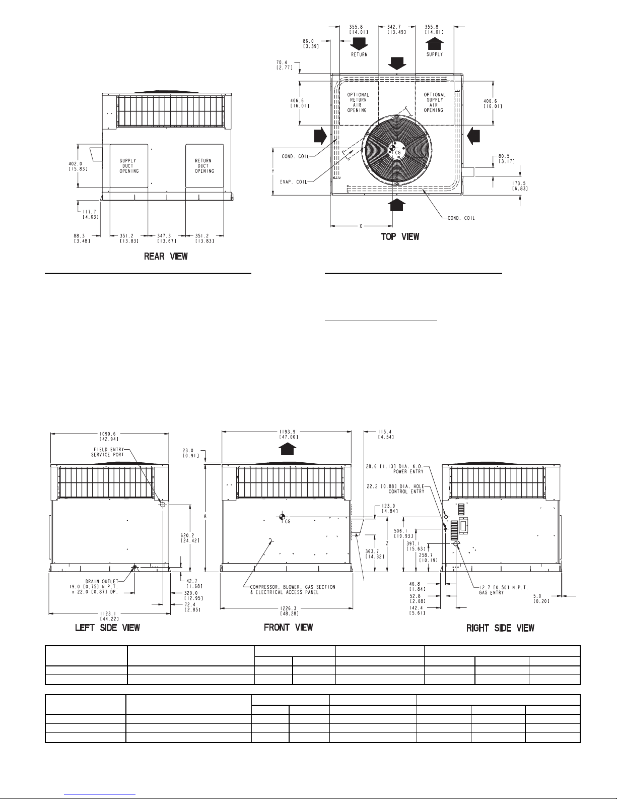
LEGEND
CG — Center of Gravity
COND — Condenser
EVAP — Evaporator
NEC — National Electrical Code
REQ’D — Required
NOTE: Dimensions are in mm [in.]
UNIT
ELECTRICAL
CHARACTERISTICS
UNIT WEIGHT UNIT HEIGHT in. [mm] CENTER OF GRAVITY in. [mm]
lb kg A X Y Z
582A048090/115/130 208-230/1/60, 208/230-3-60, 460-3-60 415 188.6 38.98 [990.2] 22 [558.5] 16 [406.4] 17 [432.0]
582A060090/115/130 208/230-1-60, 208/230-3-60, 460-3-60 450 204.5 38.98 [990.2] 22 [558.5] 16 [406.4] 17 [432.0]
UNIT
ELECTRICAL
CHARACTERISTICS
UNIT WEIGHT UNIT HEIGHT in. [mm] CENTER OF GRAVITY in. [mm]
lb kg A X Y Z
583A042060/090 208/230-1-60, 208/230-3-60, 460-3-60 382.0 842.2 38.98 [990.2] 23.0 [584.2] 16.3 [412.8] 16.6 [421.6]
583A048090/115/130 208/230-1-60, 208/230-3-60, 460-3-60 421.0 928.2 38.98 [990.2] 21.5 [546.1] 16.6 [422.1] 18.0 [457.2]
583A060090/115/130 208/230-1-60, 208/230-3-60, 460-3-60 468.0 1031.7 42.98 [1091.7] 23.5 [596.9] 16.3 [412.8] 17.6 [447.0]
Fig. 3 — 582A048,060 and 583A042,048,060 Unit Dimensions
—3—

RECEIVING AND INSTALLATION
I. STEP 1 — CHECK EQUIPMENT
A. Identify Unit
The unit model number and serial number are stamped on
unit identification plate. Check this information against shipping papers and job data.
B. Inspect Shipment
Inspect for shipping damage while unit is still on shipping
pallet. If unit appears to be damaged or is torn loose from its
anchorage, have it examined by transportation inspectors before removal. Forward claim papers directly to transportation company. Manufacturer is not responsible for any damage incurred in transit.
Check all items against shipping list. Immediately notify the
nearest Bryant Air Conditioning office if any item is missing.
To prevent loss or damage, leave all parts in original packages until installation.
II. STEP 2 — PROVIDE UNIT SUPPORT
A. Roof Curb
Install accessory roof curb in accordance with instructions
shipped with curb. See Fig. 4 for roof curb dimensions. Install insulation, cant strips, roofing, and flashing. Ductwork
must be attached to curb.
IMPORTANT: The gasketing of the unit to the roof curb is
critical for a watertight seal. Install gasketing material supplied with the roof curb. Improperly applied gasketing can
result in water leaks, air leaks, and poor unit performance.
Curb should be level to within
1
⁄4inch. This is necessary for
unit drain to function properly. Refer to accessory roof curb
installation instructions for additional information as
required.
B. Slab Mount
Place the unit on a solid, level concrete pad that is a minimum of 4 in. thick with 2 in. above grade. The slab should be
flush on the compressor end of the unit (to allow condensate
drain installation) and should extend 2 in. on the three remaining sides of the unit. See Fig. 5. Do not secure the unit
to the slab except when required by local codes.
C. Ground Mount
The unit may be installed either on a slab or placed directly
on the ground if local codes permit. Place the unit on level
ground prepared with gravel for condensate discharge.
III. STEP 3 — FIELD FABRICATE DUCTWORK
Secure all ducts to roof curb and building structure on vertical discharge units. Do not connect ductwork to unit. For horizontal applications, unit is provided with flanges on the horizontal openings.All ductwork should be secured to the flanges.
Insulate and weatherproof all external ductwork, joints,
and roof openings with counter flashing and mastic in
accordance with applicable codes.
Ducts passing through an unconditioned space must be insulated and covered with a vapor barrier.
If a plenum return is used on a vertical unit, the return should
be ducted through the roof deck to comply with applicable
fire codes.
Aminimum clearance is not required around ductwork. Cabinet return-air static shall not exceed −.25 in. wg.
IV. STEP 4 — PROVIDE CLEARANCES
The required minimum operating and service clearances are
shown in Fig. 2 and 3. Adequate combustion, ventilation, and
condenser air must be provided, in accordance with section
5.3, Air for Combustion and Ventilation, of the National Fuel
Gas CodeANSI (American National Standards Institute) Z223.1
(in Canada, sections 7.2, 7.3 or 7.4 or Can/CGA [Canadian
Gas Association] B149 Installation Codes), or applicable provisions of local building code.
CAUTION:
Do not restrict condenser airflow. An air
restriction at either the outdoor-air inlet or the fan discharge can be detrimental to compressor life.
The condenser fan pulls air through the condenser coil and
discharges it through the top cover. Be sure that the fan discharge does not recirculate to the condenser coil. Do not locate the unit in either a corner or under an overhead obstruction.
The minimum clearance under a partial overhang (such as a
normal house overhang) is 48-in. above the unit top. The maximum horizontal extension of a partial overhang must not exceed 48 inches.
Do not place the unit where water, ice, or snow from
an overhang or roof will damage or flood the unit. Do not install the unit on carpeting, tile, or other combustible
materials. The unit may be installed on wood flooring or on
Class A, B, or C roof covering materials.
V. STEP 5 — RIG AND PLACE UNIT
CAUTION:
When installing the unit on a rooftop, be
sure the roof will support the additional weight.
Use spreader bars or crate top when rigging the unit. The
units must be rigged for lifting as shown in Fig. 6. Refer to
Tables 1 and 2 for operating weight. Use extreme caution to
prevent damage when moving the unit. Unit must remain in
an upright position during all rigging and moving operations. The unit must be level for proper condensate drainage;
therefore, the ground-level pad or accessory roof curb must
be level before setting the unit in place. When a fieldfabricated support is used, be sure that the support is level
and properly supports the unit.
—4—
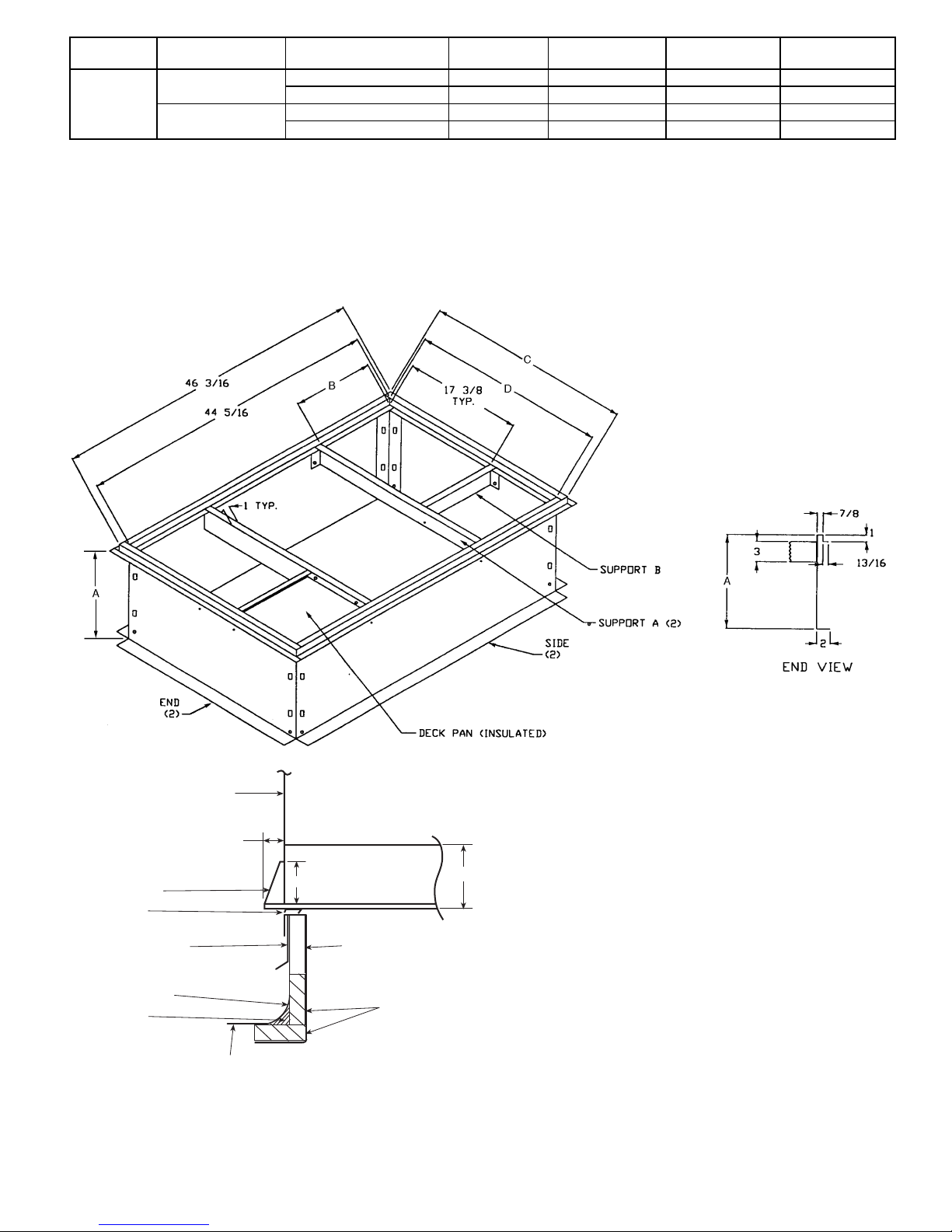
UNIT SIZE PART NUMBER
A
in. [mm]
B
in. [mm]
C
in. [mm]
D
in. [mm]
FLAT
CURB
582A018-042
583A024-036
CPRFCURB006A00 8 [203] 11
27
⁄32[301] 305⁄8[778] 283⁄4[730]
CPRFCURB007A00 14 [356] 11
27
⁄32[301] 305⁄8[778] 283⁄4[730]
582A048, 060
583A042-060
CPRFCURB008A00 8 [203] 15
27
⁄32[402] 421⁄8[1070] 401⁄4[1022]
CPRFCURB009A00 14 [356] 15
27
⁄32[402] 421⁄8[1070] 401⁄4[1022]
NOTES:
1. Roof curb must be set up for unit being installed.
2. Seal strip must be applied as required to unit being installed.
3. Dimensions in [ ] are in millimeters.
4. Roof curb is made of 16 gage steel.
5. Table lists only the dimensions per part number that have changed.
6. Attach ductwork to curb (flanges of duct rest on curb).
7. Insulated panels: 1-in. thick fiberglass 1 lb density.
8. Dimensions are in inches.
3.0"
4.0"
BASE PAN
BOTTOM SUPPLY
0.75"
SIDE PANEL
SUPPORT RIB(S)
COUNTER FLASHING
(FIELD SUPPLIED)
NAILER
ROOFING FELT
(FIELD SUPPLIED)
CANT STRIP
(FIELD SUPPLIED)
ROOFING MATERIAL
(FIELD SUPPLIED)
INSULATION
(FIELD SUPPLIED)
SEAL STRIP
(FACTORY SUPPLIED)
FULL PERIMETER CURB
Fig. 4 — Roof Curb Dimensions
—5—
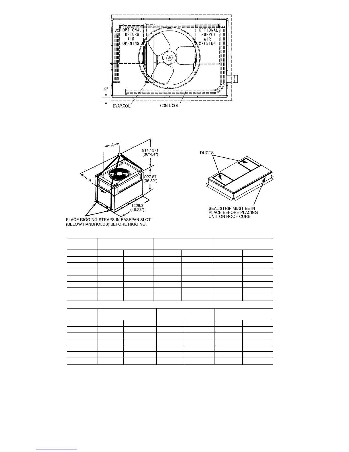
Fig. 5 — Slab Mounting Details
UNIT
582A
MAXIMUM
WEIGHT
AB
Size lb kg in. mm in. mm
018 271 123.2 20.0 508.0 14.0 355.6
024 302 137.3 22.5 571.5 13.0 330.2
030 302 137.3 21.5 546.1 13.75 349.3
036 336 152.7 22.5 571.5 14.0 355.6
042 377 171.4 21.5 546.1 13.5 342.9
048 437 198.6 22.0 558.5 17.0 432.0
060 472 214.5 22.0 558.5 17.0 432.0
UNIT
583A
MAXIMUM
WEIGHT
AB
Size lb kg in. mm in. mm
024 312 688.0 22.0 558.5 14.5 368.3
030 335 738.7 22.0 558.5 15.3 388.6
036 343 756.4 22.0 558.5 15.3 388.6
042 404 890.9 23.0 584.2 16.3 414.0
048 443 976.9 21.5 546.1 16.3 414.0
060 490 1080.5 23.5 596.9 16.3 414.3
Fig. 6 — Suggested Rigging
—6—
VI. STEP 6 — CONNECT CONDENSATE DRAIN
NOTE: When installing condensate drain connection be sure
to comply with local codes and restrictions.
Models 582A and 583A dispose of condensate water through
a
3
⁄4in. NPT fitting which exits through the compressor ac-
cess panel. See Fig. 2 and 3 for location.
Condensate water can be drained directly onto the roof in roof-
top installations (where permitted) or onto a gravel apron in
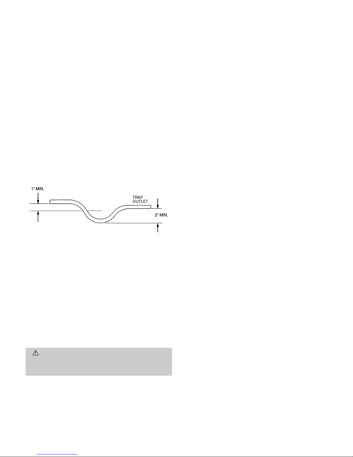
ground-level installations. Install a field-supplied condensate trap at end of condensate connection to ensure proper
drainage. Make sure that the outlet of the trap is at least
1 in. lower than the drain-pan condensate connection to prevent the pan from overflowing. See Fig. 7. Prime the trap with
water. When using a gravel apron, make sure it slopes away
from the unit.
If the installation requires draining the condensate water away
from the unit, install a 2-in. trap at the condensate connection to ensure proper drainage. See Fig. 7. Make sure that
the outlet of the trap is at least 1 in. lower than the drainpan condensate connection to prevent the pan from overflowing. Prime the trap with water. Connect a drain tube using a
minimum of
3
⁄4-in. PVC or3⁄4-in. copper pipe (all fieldsupplied) at the outlet end of the 2-in. trap. Do not undersize
the tube. Pitch the drain tube downward at a slope of at least
one in. for every 10 ft of horizontal run. Be sure to check the
drain tube for leaks.
VII. STEP 7 — INSTALL FLUE HOOD
The flue hood assembly is shipped screwed to the coil panel
in the indoor blower compartment. Remove the service access panel to locate the assembly.
For units being installed in California Air Quality Management Districts which require NO
x
emissions of 40 nanograms/
joule or less, a field-installed low NO
x
kit must be installed.
For 40,000 and 60,000 Btuh input models, use kit part number CPLOWNOX002A00. This kit contains two NO
x
reduction baffles and one conversion label. For 90,000 115,000 and
130,000 Btuh input models, use kit part number
CPLOWNOX003A00. This kit contains three NO
x
reduction
baffles and one conversion label.
CAUTION:
The venting system is designed to ensure proper venting. The flue hood assembly must be
installed as indicated in this section of the unit installation instructions.
Install the flue hood as follows:
1. This installation must conform with local building codes
and with the National Fuel Gas Code (NFGC), ANSI
Z223.1 (in Canada, CAN/CGA B149.1, and B149.2) or
NFPA (National Fire Protection Association) latest revision. Refer to Provincial and local plumbing or wastewater codes and other applicable local codes.
2. Remove flue hood from shipping location (inside the blower
compartment). Place vent cap assembly over flue panel.
Orient screw holes in vent cap with holes in the flue panel.
3. Secure flue hood to flue panel by inserting a single screw
on the right side and the left side of the hood.
VIII. STEP 8 — INSTALL GAS PIPING
The gas supply pipe enters the unit through the access hole
provided. The gas connection to the unit is made to the
1
⁄2-in.
FPT gas inlet on the manual shutoff or gas valve.
Install a gas supply line that runs to the heating section. Re-
fer to Table 3 and the NFGC for gas pipe sizing. Do not use
cast-iron pipe. It is recommended that a black iron pipe is
used. Check the local utility for recommendations concerning existing lines. Size gas supply piping for 0.5 in. wg maximum pressure drop. Never use pipe smaller than the
1
⁄2-in.
FPT gas inlet on the unit gas valve.
For natural gas applications, the gas pressure at unit gas connection must not be less than 4.0 in. wg or greater than
13 in. wg while the unit is operating. For propane applications, the gas pressure must not be less than 4.0 in. wg or
greater than 13 in. wg at the unit connection.
An
1
⁄8-in. NPT plugged tapping accessible for test gage connection must be installed immediately upstream of the gas
supply connection to the gas valve.
When installing the gas supply line, observe local codes pertaining to gas pipe installations. Refer to the NFGC ANSI
Z223.1-1988 NFPAlatestedition(in Canada, CAN/CGAB149.1,
(2)-M86). In the absence of local building codes, adhere to the
following pertinent recommendations:
1. Avoid low spots in long runs of pipe. Grade all pipe
1
⁄4inch in every 15 ft to prevent traps. Grade all horizontal runs downward to risers. Use risers to connect to
heating section and to meter.
2. Protect all segments of piping system against physical
and thermal damage. Support all piping with appropriate straps, hangers, etc. Use a minimum of one hanger
every 6 ft. For pipe sizes larger than
1
⁄2in., follow rec-
ommendations of national codes.
3. Apply joint compound (pipe dope) sparingly and only to
male threads of joint when making pipe connections. Use
only pipe dope that is resistant to action of liquefied
petroleum gases as specified by local and/or national codes.
Never use Teflon tape.
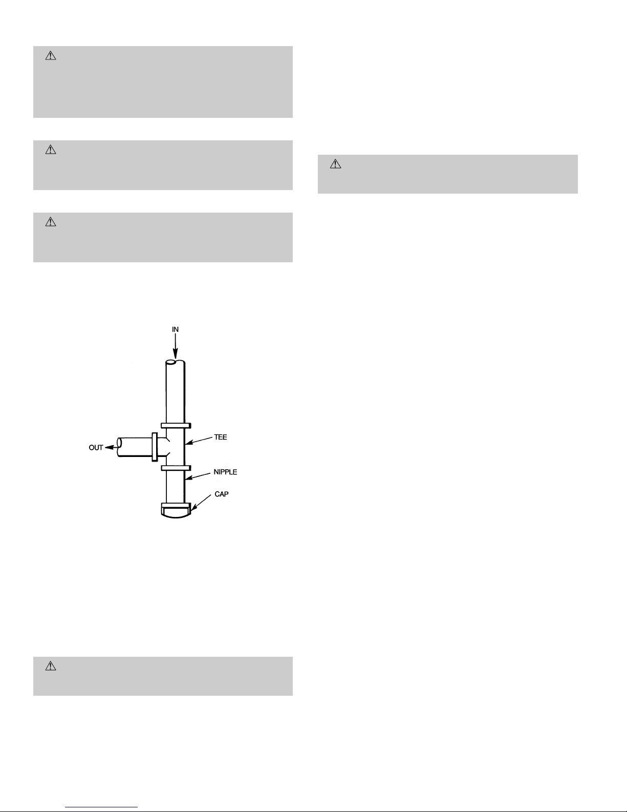
4. Install sediment trap in riser leading to heating section
per Fig. 8. This drip leg functions as a trap for dirt and
condensate.
5. Install an accessible, external, manual main shutoff valve
in gas supply pipe within 6 ft of heating section.
6. Install ground-joint union close to heating section between unit manual shutoff and external manual main
shutoff valve.
7. Pressure-test all gas piping in accordance with local and
national plumbing and gas codes before connecting piping to unit.
NOTE: Pressure test the gas supply system after the gas sup-
ply piping is connected to the gas valve. The supply piping
must be disconnected from the gas valve during the testing of the piping systems when test pressure is in excess of
0.5 psig. Pressure test the gas supply piping system at pressures equal to or less than 0.5 psig. The unit heating section
must be isolated from the gas piping system by closing the
external main manual shutoff valve and slightly opening the
ground-joint union.
Fig. 7 — Condensate Trap
—7—
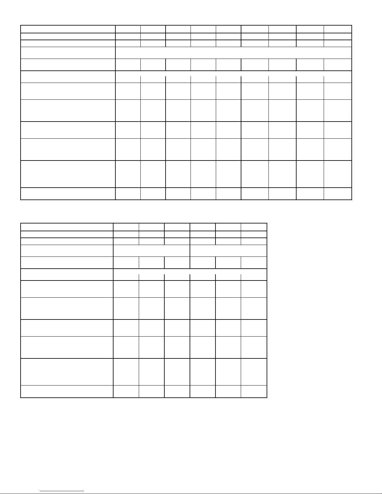
Table 1 — Physical Data — Unit 582A
UNIT SIZE 582A 018040 024040 024060 030040 030060 036060 036090 042060 042090
NOMINAL CAPACITY (ton) 1
1
⁄
2
222
1
⁄
2
2
1
⁄
2
333
1
⁄
2
3
1
⁄
2
OPERATING WEIGHT (lb) 249 280 280 280 280 314 314 355 355
COMPRESSORS Reciprocating
Quantity 1
REFRIGERANT (R-22)
Quantity (lbs) 2.6 3.5 3.5 3.65 3.65 3.75 3.75 5.7 5.7
REFRIGERANT METERING DEVICE Acutrol™ Device
Orifice ID (in.) .034 .034 .034 .034 .034 .032 .032 .034 .034
CONDENSER COIL
Rows...Fins/in. 1...17 1...17 1...17 1...17 1...17 1...17 1...17 1...17 1...17
Face Area (sq ft) 6.1 9.1 9.1 9.1 9.1 9.1 9.1 9.1 9.1
CONDENSER FAN
Nominal Cfm 2000 2400 2400 2400 2400 3000 3000 3000 3000
Diameter (in.) 22 22 22 22 22 22 22 22 22
Motor Hp (Rpm)
1
⁄8(825)1⁄8(825)1⁄8(825)1⁄8(825)1⁄8(825)1⁄4(1100)1⁄4(1100)1⁄4(1100)1⁄4(1100)
EVAPORATOR COIL
Rows...Fins/in. 2...15 2...15 2...15 2...15 2...15 3...15 3...15 4...15 4...15
Face Area (sq ft) 3.1 3.1 3.1 3.1 3.1 3.1 3.1 3.1 3.1
EVAPORATOR BLOWER
Nominal Airflow (Cfm) 600 800 800 1000 1000 1200 1200 1400 1400
Size (in.) 10x10 10x10 10x10 10x10 10x10 11x10 11x10 11x10 11x10
Motor (Hp)
1
⁄
4
1
⁄
4
1
⁄
4
1
⁄
4
1
⁄
4
1
⁄
2
1
⁄
2
3
⁄
4
3
⁄
4
FURNACE SECTION*
Burner Orifice No. (Qty...Drill Size)
Natural Gas
2...45 2...45 2...38 2...45 2...38 2...38 3...38 2...38 3...38
Burner Orifice No. (Qty...Drill Size)
Propane Gas
2...50 2...50 2...46 2...50 2...46 2...46 3...46 2...46 3...46
RETURN-AIR FILTERS (in.)†
Throwaway 20x20 20x20 20x20 20x20 20x20 20x24 20x24 20x24 20x24
UNIT SIZE 582A 048090 048115 048130 060090 060115 060130
NOMINAL CAPACITY (ton) 444555
OPERATING WEIGHT (lb) 415 415 415 450 450 450
COMPRESSORS Scroll Reciprocating
Quantity 11
REFRIGERANT (R-22)
Quantity (lbs) 6.0 6.0 6.0 8.0 8.0 8.0
REFRIGERANT METERING DEVICE Acutrol Device
Orifice ID (in.) .032 .032 .032 .030 .030 .030
CONDENSER COIL
Rows...Fins/in. 1...17 1...17 1...17 2...17 2...17 2...17
Face Area (sq ft) 12.3 12.3 12.3 12.3 12.3 12.3
CONDENSER FAN
Nominal Cfm 3600 3600 3600 3600 3600 3600
Diameter (in.) 22 22 22 22 22 22
Motor Hp (Rpm)
1
⁄4(1100)1⁄4(1100)1⁄4(1100)1⁄4(1100)1⁄4(1100)1⁄4(1100)
EVAPORATOR COIL
Rows Fins...in. 3...15 3...15 3...15 4...15 4...15 4...15
Face Area (sq ft) 4.7 4.7 4.7 4.7 4.7 4.7
EVAPORATOR BLOWER
Nominal Airflow (Cfm) 1600 1600 1600 2000 2000 2000
Size (in.) 11x10 11x10 11x10 11x10 11x10 11x10
Motor (hp)
3
⁄
4
3
⁄
4
3
⁄
4
1.0 1.0 1.0
FURNACE SECTION*
Burner Orifice No. (Qty...Drill Size)
Natural Gas
3...38 3...33 3...31 3...38 3...33 3...31
Burner Orifice No. (Qty...Drill Size)
Propane Gas
3...46 3...42 3...41 3...46 3...42 3...41
RETURN-AIR FILTERS (in.)†
Throwaway 24x30 24x30 24x30 24x30 24x30 24X30
*Based on altitude of 0 to 2000 feet.
†Required filter sizes shown are based on the larger of the ARI (Air Conditioning
and Refrigeration Institute) rated cooling airflow or the heating airflow velocity of
300 ft/min for throwaway type or 450 ft/min for high-capacity type. Air filter pressure
drop for non-standard filters must not exceed 0.08 in. wg.
—8—
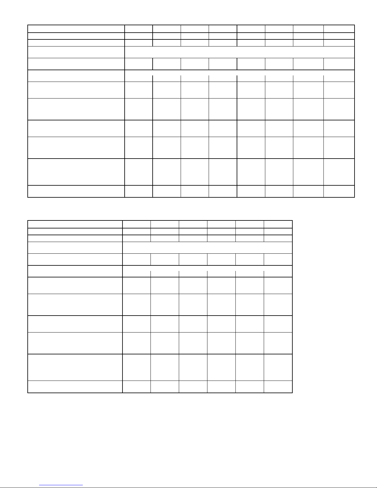
Table 2 — Physical Data — Unit 583A
UNIT SIZE 583A 024040 024060 030040 030060 036060 036090 042060 042090
NOMINAL CAPACITY (ton) 222
1
⁄
2
2
1
⁄
2
333
1
⁄
2
3
1
⁄
2
OPERATING WEIGHT (lb) 290 290 313 313 321 321 382 382
COMPRESSORS Scroll
Quantity 1
REFRIGERANT (R-22)
Quantity (lb) 3.4 3.4 4.4 4.4 5.2 5.2 6.4 6.4
REFRIGERANT METERING DEVICE
Orifice ID (in.) .034 .034 .030 .030 .032 .032 .034 .034
CONDENSER COIL
Rows...Fins/in. 1...17 1...17 1...17 1...17 2...17 2...17 2...17 2...17
Face Area (sq ft) 9.1 9.1 12.7 12.7 9.1 9.1 12.3 12.3
CONDENSER FAN
Nominal Cfm 2350 2350 2350 2350 2350 2350 3300 3300
Diameter (in.) 22 22 22 22 22 22 22 22
Motor Hp (Rpm)
1
⁄8(825)1⁄8(825)1⁄8(825)1⁄8(825)1⁄8(825)1⁄8(825)1⁄4(1100)1⁄4(1100)
EVAPORATOR COIL
Rows...Fins/in. 3...15 3...15 3...15 3...15 3...15 3...15 3...15 3...15
Face Area (sq ft) 3.1 3.1 3.1 3.1 3.7 3.7 4.7 4.7
EVAPORATOR BLOWER
Nominal Airflow (Cfm) 800 800 1000 1000 1200 1200 1400 1400
Size (in.) 10x10 10x10 10x10 10x10 11x10 11x10 11x10 11x10
Motor (Hp)
1
⁄
4
1
⁄
4
1
⁄
4
1
⁄
4
1
⁄
2
1
⁄
2
3
⁄
4
3
⁄
4
FURNACE SECTION*
Burner Orifice No. (Qty...Drill Size)
Natural Gas
2...44 2...38 2...44 2...38 2...38 3...38 2...38 3...38
Burner Orifice No. (Qty...Drill Size)
Propane Gas
2...50 2...46 2...50 2...46 2...46 3...46 2...46 3...46
RETURN-AIR FILTERS (in.)†
Throwaway 20x20 20x20 20x20 20x20 20x24 20x24 24x30 24x30
UNIT SIZE 583A 048090 048115 048130 060090 060115 060130
NOMINAL CAPACITY (ton) 444555
OPERATING WEIGHT (lb) 421 421 421 468 468 468
COMPRESSORS Scroll
Quantity 1
REFRIGERANT (R-22)
Quantity (lb) 7.2 7.2 7.2 8.1 8.1 8.1
REFRIGERANT METERING DEVICE Acutrol Device
Orifice ID (in.) .034 .034 .034 .032 .032 .032
CONDENSER COIL
Rows...Fins/in. 2...17 2...17 2...17 2...17 2...17 2...17
Face Area (sq ft) 12.3 12.3 12.3 16.4 16.4 16.4
CONDENSER FAN
Nominal Cfm 3300 3300 3300 3300 3300 3300
Diameter (in.) 22 22 22 22 22 22
Motor Hp (Rpm)
1
⁄4(1100)1⁄4(1100)1⁄4(1100)1⁄4(1100)1⁄4(1100)1⁄4(1100)
EVAPORATOR COIL
Rows Fins...in. 4...15 4...15 4...15 4...15 4...15 4...15
Face Area (sq ft) 4.7 4.7 4.7 4.7 4.7 4.7
EVAPORATOR BLOWER
Nominal Airflow (Cfm) 1600 1600 1600 1750 1750 1750
Size (in.) 11x10 11x10 11x10 11x10 11x10 11x10
Motor (Hp)
3
⁄
4
3
⁄
4
3
⁄
4
1.0 1.0 1.0
FURNACE SECTION*
Burner Orifice No. (Qty...Drill Size)
Natural Gas
3...38 3...33 3...31 3...38 3...33 3...31
Burner Orifice No. (Qty...Drill Size)
Propane Gas
3...46 3...42 3...41 3...46 3...42 3...41
RETURN-AIR FILTERS (in.)†
Throwaway 24x30 24x30 24x30 24x30 24x30 24X30
*Based on altitude of 0 to 2000 feet.
†Required filter sizes shown are based on the larger of the ARI (Air Conditioning
and Refrigeration Institute) rated cooling airflow or the heating airflow velocity of
300 ft/min for throwaway type or 450 ft/min for high-capacity type. Air filter pressure
drop for non-standard filters must not exceed 0.08 in. wg.
—9—
(Text continued from page 7)
CAUTION:
Unstable operation may occur when the
gas valve and manifold assembly are forced out of position while connecting improperly-routed rigid gas piping to the gas valve. Use a backup wrench when making connection to avoid strain on, or distortion of, the
gas control piping.
CAUTION:
If a flexible conductor is required or allowed by the authority having jurisdiction, black iron
pipe shall be installed at the gas valve and shall extend a minimum of 2 in. outside the unit casing.
WARNING:
Never use a match or other open flame
when checking for gas leaks. Never purge gas line into
combustion chamber.Failure to follow this warning could
result in an explosion causing personal injury or death.
8. Check for gas leaks at the field-installed and factoryinstalled gas lines after all piping connections have been
completed. Use soap-and-water solution (or method specified by local codes and/or regulations).
IX. STEP 9 — INSTALL DUCT CONNECTIONS
The unit has duct flanges on the supply- and return-air openings on the side and bottom of the unit. For downshot applications the ductwork connects to the roof curb. See Fig. 2 and
3 for connection sizes and locations.
A. Configuring Units for Downflow (Vertical) Discharge
WARNING:
Before performing service or maintenance operations on the system, turn off main power to
unit or electrical shock could result.
1. Open all electrical disconnects before starting any service work.
2. Remove return duct cover located on duct panel by breaking connecting tabs with screwdriver and a hammer
(Fig. 9).
3. To remove supply duct cover, break front and right side
connecting tabs with a screwdriver and a hammer. Push
louver down to break rear and left side tabs (Fig. 10).
4. If unit ductwork is to be attached to vertical opening
flanges on the unit basepan (jackstand applications only),
do so at this time.
CAUTION:
Collect ALL screws that were removed.
Do not leave screws on rooftop as permanent damage
to the roof may occur.
5. It is recommended that the basepan insulation around
the perimeter of the vertical return-air opening be
secured to the basepan with aluminum tape.Applicable
local codes may require aluminum tape to prevent
exposed fiberglass.
6. Cover both horizontal duct openings with the duct covers from the accessory duct cover kit. Ensure opening is
air- and watertight.
7. After completing unit conversion, perform all safety checks
and power up unit.
NOTE: The design and installation of the duct system must
be in accordance with the standards of the NFPA for installation of nonresidence-type air conditioning and ventilating
systems, NFPA 90A or residence-type, NFPA 90B; and/or local codes and residence-type, NFPA 90B; and/or local codes
and ordinances.
Adhere to the following criteria when selecting, sizing,
and installing the duct system:
1. Units are shipped for side shot installation.
2. Select and size ductwork, supply-air registers, and
return-air grilles according to American Society of
Heating, Refrigeration and Air Conditioning Engineers
(ASHRAE) recommendations.
3. Use flexible transition between rigid ductwork and unit
to prevent transmission of vibration. The transition may
be screwed or bolted to duct flanges. Use suitable gaskets to ensure weathertight and airtight seal.
4. All units must have field-supplied filters or accessory filter rack installed in the return-air side of the unit. Recommended sizes for filters are shown in Tables 1 and 2.
5. Size all ductwork for maximum required airflow (either
heating or cooling) for unit being installed. Avoid abrupt
duct size increases or decreases or performance may be
affected.
6. Adequately insulate and weatherproof all ductwork
located outdoors. Insulate ducts passing through unconditioned space, and use vapor barrier in accordance with
latest issue of Sheet Metal and Air Conditioning
Contractors National Association (SMACNA) and Air
Conditioning Contractors of America (ACCA) minimum
installation standards for heating and air conditioning
systems. Secure all ducts to building structure.
7. Flash, weatherproof, and vibration-isolate all openings
in building structure in accordance with local codes and
good building practices.
Fig. 8 — Sediment Trap
—10—

Table 3 — Maximum Gas Flow Capacity*
NOMINAL
IRON PIPE,
SIZE
(in.)
INTERNAL
DIAMETER
(in.)
LENGTH OF PIPE, FT†
10 20 30 40 50 60 70 80 90 100 125 150 175 200
1
⁄
2
.622 175 120 97 82 73 66 61 57 53 50 44 40 — —
3
⁄
4
.824 360 250 200 170 151 138 125 118 110 103 93 84 77 72
1 1.049 680 465 375 320 285 260 240 220 205 195 175 160 145 135
1
1
⁄
4
1.380 1400 950 770 600 580 530 490 460 430 400 360 325 300 280
1
1
⁄
2
1.610 2100 1460 1180 990 900 810 750 690 650 620 550 500 460 430
*Capacity of pipe in cu ft of gas per hr for gas pressure of 0.5 psig or less. Pressure drop of 0.5-in. wg (based on
a 0.60 specific gravity gas). Refer to Table C-4, National Fire Protection Association NFPA 54.
†This length includes an ordinary number of fittings.
X. STEP 10 — INSTALL ELECTRICAL CONNECTIONS
WARNING:
The unit cabinet must have an uninterrupted, unbroken electrical ground to minimize the possibility of personal injury if an electrical fault should
occur .This ground may consist of an electrical wire connected to the unit ground lug in the control compartment, or conduit approved for electrical ground when
installed in accordance with NEC (National Electrical
Code) ANSI/NFPA (latest edition) (in Canada, Canadian Electrical Code CSA [Canadian Standards Association] C22.1) and local electrical codes. Do not use gas
piping as an electrical ground. Failure to adhere to this
warning could result in personal injury or death.
CAUTION:
Failure to follow these precautions could
result in damage to the unit being installed:
1. Make all electrical connections in accordance with NEC
ANSI/NFP A(latest edition) and local electrical codes governing such wiring. In Canada, all electrical connections must be in accordance with CSA standard C22.1
Canadian Electrical Code Part 1 and applicable local codes.
Refer to unit wiring diagram.
2. Use only copper conductor for connections between fieldsupplied electrical disconnect switch and unit. DO NOT
USE ALUMINUM WIRE.
3. Be sure that high-voltage power to unit is within operating voltage range indicated on unit rating plate.
4. Do not damage internal components when drilling through
any panel to mount electrical hardware, conduit, etc. On
3-phase units, ensure phases are balanced within 2%.
Consult local power company for correction of improper
voltage and/or phase imbalance.
A. High-Voltage Connections
The unit must have a separate electrical service with a fieldsupplied, waterproof, disconnect switch mounted at, or within
sight from, the unit. Refer to the unit rating plate for maximum fuse/circuit breaker size and minimum circuit amps (ampacity) for wire sizing. See Tables 4 and 5 for electrical data.
The field-supplied disconnect switch box may be mounted on
the unit over the high-voltage inlet hole when the standard
power and low-voltage entry points are used. See Fig. 2 and
3 for acceptable location.
See unit wiring label and Fig. 11 for reference when making
high voltage connections. Proceed as follows to complete the
high-voltage connections to the unit.
Fig. 9 — Supply and Return Duct Openings
Fig. 10 — Vertical Duct Cover Removed
—11—
Single phase units:
1. Run the high-voltage (L1, L2) and ground leads into the
control box.
2. Connect ground lead to chassis ground connection.
3. Connect L1 to pressure lug connection 11 of the compressor contactor.
4. Connect L2 to pressure lug connection 23 of the compressor contactor.
Three phase units:
1. Run the high-voltage (L1, L2, L3) and ground leads into
the control box.
2. Connect ground lead to chassis ground connection.
3. Locate the black and yellow wires connected to the lines
side of the contactor.
4. Connect field L1 to black wire on connection 11 of the
compressor contactor.
5. Connect field wire L2 to yellow wire on connection 13 of
the compressor contactor.
6. Connect field wire L3 to blue wire from compressor.
B. Special Procedures for 208-v Operation
WARNING:
Make sure that the gas supply then the
power supply to the unit is switched OFF before making any wiring changes. Electrical shock can cause personal injury or death.
C. Control Voltage Connections
NOTE: Do not use any type of power-stealing thermostat. Unit
control problems may result.
Table 4 — Electrical Data — Unit 582A
UNIT
SIZE
582A
V-PH-Hz
VOLTAGE
RANGE
COMPRESSOR
OUTDOOR FAN
MOTOR
INDOOR FAN
MOTOR
POWER SUPPLY FUSE OR
HACR BRKR
Min Max RLA LRA FLA FLA MCA MOCP*
018 208/230-1-60 187 253 9.0 45.0 0.8 1.8 13.9 20
024 208/230-1-60 187 253 12.8 61.0 0.8 2.0 18.8 30
030
208/230-1-60 187 253 14.4 73.0 0.8 2.0 20.8 30
208/230-3-60 187 253 12.6 68.0 0.8 2.0 13.2 20
036
208/230-1-60 187 253 15.1 81.0 1.6 3.6 24.1 35
208/230-3-60 187 253 10.9 78.0 1.6 3.6 18.8 25
460-3-60 414 506 5.8 40.0 0.9 1.9 10.1 15
042
208/230-1-60 187 253 18.6 105.0 1.6 3.8 27.5 45
208/230-3-60 187 253 10.7 85.0 1.6 3.8 18.8 25
460-3-60 414 506 5.3 42.0 0.9 2.0 9.5 15
048
208-230/1/60 197 253 25.3 131.0 1.6 3.8 37.0 60
208/230-3-60 187 253 13.5 108.0 1.6 3.8 22.3 35
460-3-60 414 506 6.7 47.5 0.9 2.0 11.3 15
060
208/230-1-60 187 253 28.9 147.0 1.6 6.2 43.9 60
208/230-3-60 187 253 18.6 125.0 1.6 6.2 31.1 45
460-3-60 414 506 8.5 66.5 0.9 3.2 14.7 20
LEGEND
FLA — Full Load Amps
HACR — Heating, Air Conditioning and
Refrigeration
LRA — Locked Rotor Amps
MCA — Minimum Circuit Amps
MOCP — Maximum Overcurrent Protection
RLA — Rated Load Amps
*Fuse or HACR Breaker.
NOTES:
1. In compliance with NEC (National Electrical Code) requirements for
multimotor and combination load equipment (refer to NEC
Articles 430 and 440), the overcurrent protective device for the unit
shall be fuse or HACR breaker. The CGA (Canadian Gas
Association) units may be fuse or circuit breaker.
2. Minimum wire size is based on 60 C copper wire. If other than
60 C wire is used, or if length exceeds wire length in table,
determine size from NEC.
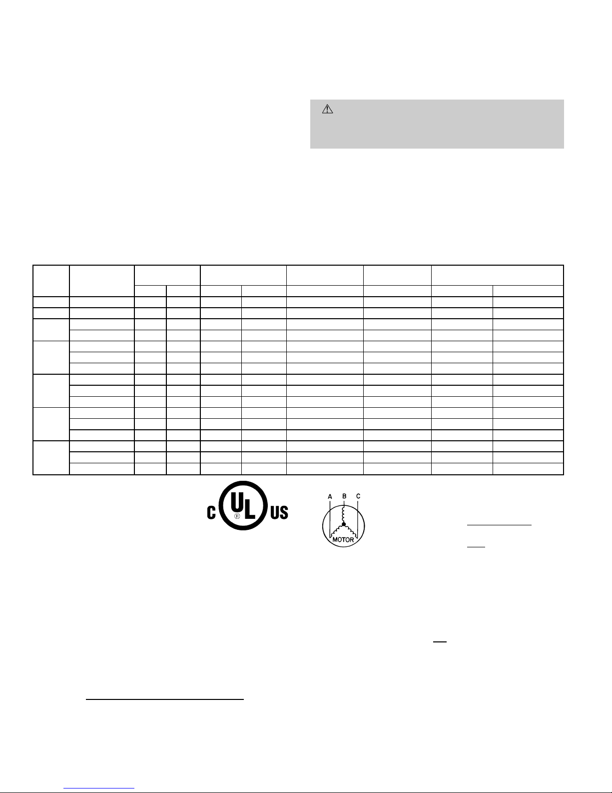
3. Unbalanced 3-Phase Supply Voltage
Never operate a motor where a phase imbalance in supply voltage is
greater than 2%.
Use the following formula to determine the percent-
age of voltage imbalance.
% Voltage imbalance
max voltage deviation from average voltage
= 100 x
average voltage
EXAMPLE: Supply voltage is 460-3-60.
AB = 452 v
BC = 464 v
AC = 455 v
452 1 464 1 455
Average Voltage =
3
1371
=
3
= 457
Determine maximum deviation from average voltage.
(AB) 457 − 452=5v
(BC) 464 − 457=7v
(AC) 457 − 455=2v
Maximum deviation is 7 v.
Determine percent of voltage imbalance.
7
% Voltage Imbalance = 100 x
457
= 1.53%
This amount of phase imbalance is satisfactory as it is below the maximum allowable 2%.
IMPORT ANT: If the supply voltage phase imbalance is more than 2%,
contact your local electric utility company immediately.
—12—
 Loading...