

Bryant 581Jx14 series Installation Instructions Manual

581J*14
SINGLE PACKAGE ROOFTOP, GAS HEATING/ELECTRIC COOLING
WITH PURON
SIZE 14
R
(R--410A) REFRIGERANT
Installation Instructions
NOTE: Read the entire instruction manual before starting
the installation
TABLE OF CONTENTS
SAFETY CONSIDERATIONS 2....................
Rated Indoor Airflow (cfm) 3.....................
INSTALLATION 6...............................
Jobsite Survey 6................................
Step 1 -- Plan for Unit Location 6..................
Roof Mount 6...............................
Step 2 -- Plan for Sequence of Unit Installation 7......
Curb--Mount Installation 7.....................
Pad--Mount Installation 7......................
Frame--Mount Installation 7....................
Step 3 -- Inspect Unit 7...........................
Step 4 -- Provide Unit Support 7...................
Roof Curb Mount 7..........................
Slab Mount (Horizontal Units Only) 9...........
Alternate Unit Support 9......................
Step 5 -- Field Fabricate Ductwork 9................
Step 6 -- Rig and Place Unit 9.....................
Positioning on Curb 10.......................
Step 7 -- Convert to Horizontal and Connect Ductwork 11
Step 8 -- Install Outside Air Hood 11...............
Economizer Hood Removal and Setup —
Factory Option 11...........................
Two Position Damper Hood Removal and Setup —
Factory Option 11...........................
Economizer Hood and Two--Position Hood 12.....
Step 9 -- Install Flue Hood 13.....................
Step 10 -- Install Gas Piping 13....................
Factory--Option Thru--Base Connections
(Gas Connections) 14.........................
Step 11 -- Install External Condensate Trap and Line 16..
Step 12 -- Make Electrical Connections 16...........
Field Power Supply 16........................
All Units 18................................
Units without Factory--Installed
Non--Fused Disconnect 18.....................
Units with Factory--Installed
Non--Fused Disconnect 18.....................
Convenience Outlets 19.......................
Factory--Option Thru--Base Connections
(Electrical Connections) 21....................
Units without Thru--Base Connections 21.........
Field Control Wiring 21.......................
Thermostat 21...............................
Unit without Thru--Base Connection Kit 22.......
Heat Anticipator Settings 22...................
Low Ambient Control (Factory Option) 22...........
Variable Frequency Drive (VFD)
2--Speed Indoor Fan Motor System (Factory Option) 22.
EconoMi$er X -- Ultra Low Leak Economizer
(Factory Option) 22.............................
Perfect Humidityt Control Connections 23........
Perfect Humidity -- Space RH Controller 23.......
RTU Open Control System 25.....................
Supply Air Temperature (SAT) Sensor 28.........
Outdoor Air Temperature (OAT) Sensor 29.......
EconoMi$er2 29.............................
Field Connections 29..........................
Space Temperature (SPT) Sensors 29............
Economizer Controls 30........................
Indoor Air Quality (CO
Outdoor Air Quality Sensor 31.................
Space Humidity Sensor or Humidistat 31.........
Smoke Detector/Fire Shutdown (FSD) 32.........
Connecting Discrete Inputs 32..................
Communication Wiring -- Protocols 33............
General 33.................................
Local Access 34.............................
RTU Open Troubleshooting 34.................
Outdoor Air Enthalpy Control 35.................
Differential Enthalpy Control 35................
Return Air Enthalpy Sensor 35.................
Smoke Detectors 36...........................
Step 13 -- Adjust Factory--Installed Options 42........
Step 14 -- Install Accessories 42...................
)Sensor 30.............
2
START--UP CHECKLIST 43.......................
SAFETY CONSIDERATIONS
Improper installation, adjustment, alteration, service,
maintenance, or use can cause explosion, fire, electrical
shock or other conditions which may cause personal
injury or property damage. Consult a qualified installer,
service agency, or your distributor or branch for
information or assistance. The qualified installer or
agency must use factory--authorized kits or accessories
when modifying this product. Refer to the individual
instructions packaged with the kits or accessories when
installing.
Follow all safety codes. Wear safety glasses and work
gloves. Use quenching cloths for brazing operations and
have a fire extinguisher available. Read these instructions
thoroughly and follow all warnings or cautions attached to
the unit. Consult local building codes and appropriate
national electrical codes (in USA, ANSI/NFPA70,
National Electrical Code (NEC); in Canada, CSA C22.1)
for special requirements.
581J*14
It is important to recognize safety information. This is the
safety--alert symbol
unit and in instructions or manuals, be alert to the
potential for personal injury.
Understand the signal words DANGER, WARNING,
CAUTION, and NOTE. These words are used with the
safety--alert symbol. DANGER identifies the most serious
hazards which will result in severe personal injury or
death. WARNING signifies hazards which could result in
personal injury or death. CAUTION is used to identify
unsafe practices, which may result in minor personal
injury or product and property damage. NOTE is used to
highlight suggestions which will result in enhanced
installation, reliability, or operation.
. When you see this symbol on the
!
WARNING
FIRE, EXPLOSION HAZARD
Failure to follow this warning could result in personal
injury or death.
Disconnect gas piping from unit when leak testing at
pressure greater than 0.5 psig (3450 Pa). Pressures
greater than 0.5 psig (3450 Pa) will cause gas valve
damage resulting in hazardous condition. If gas valve
is subjected to pressure greater than 0.5 psig (3450
Pa), it must be replaced before use. When pressure
testing field--supplied gas piping at pressures of 0.5
psig (3450 Pa) or less, a unit connected to such piping
must be isolated by closing the manual gas valve.
!
WARNING
ELECTRICAL SHOCK HAZARD
Failure to follow this warning could cause personal
injury or death.
Before performing service or maintenance operations
on unit, always turn off main power switch to unit and
install lock(s) and lockout tag(s). Unit may have more
than one power switch.
!
WARNING
UNIT OPERATION AND SAFETY HAZARD
Failure to follow this warning could cause personal
injury, death and/or equipment damage.
Puronr (R--410A) refrigerant systems operate at
higher pressures than standard R--22 systems. Do not
use R--22 service equipment or components on Puron
refrigerant equipment.
!
WARNING
PERSONAL INJURY AND ENVIRONMENTAL
HAZARD
Failure to follow this warning could cause personal
injury or death.
Relieve pressure and recover all refrigerant before
system repair or final unit disposal.
Wear safety glasses and gloves when handling
refrigerants. Keep torches and other ignition sources
away from refrigerants and oils.
!
CAUTION
CUT HAZARD
Failure to follow this caution may result in personal
injury.
Sheet metal parts may have sharp edges or burrs. Use
care and wear appropriate protective clothing, safety
glasses and gloves when handling parts and servicing
air conditioning equipment.
2
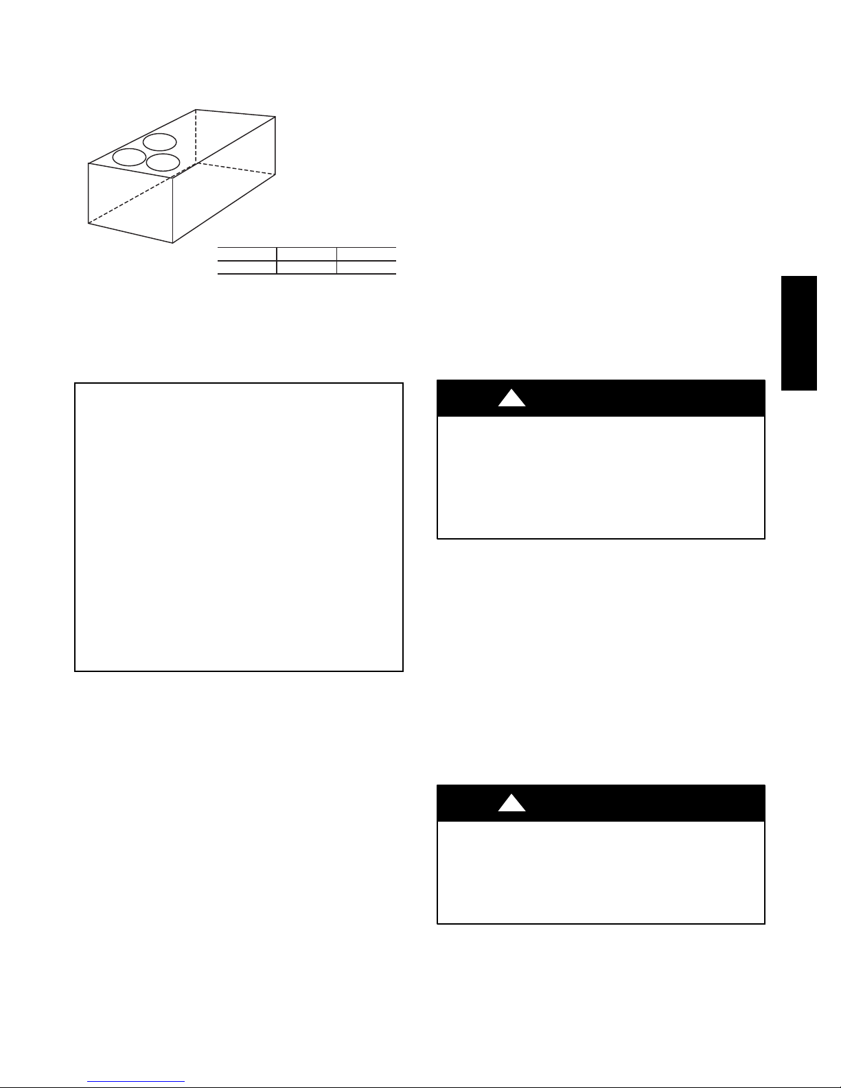
Rated Indoor Airflow (cfm)
The table to the right lists the rated indoor airflow used
for the AHRI efficiency rating for the units covered in this
document.
Model Number Full Load Airflow (cfm)
581J*14D/F/K/M 4375
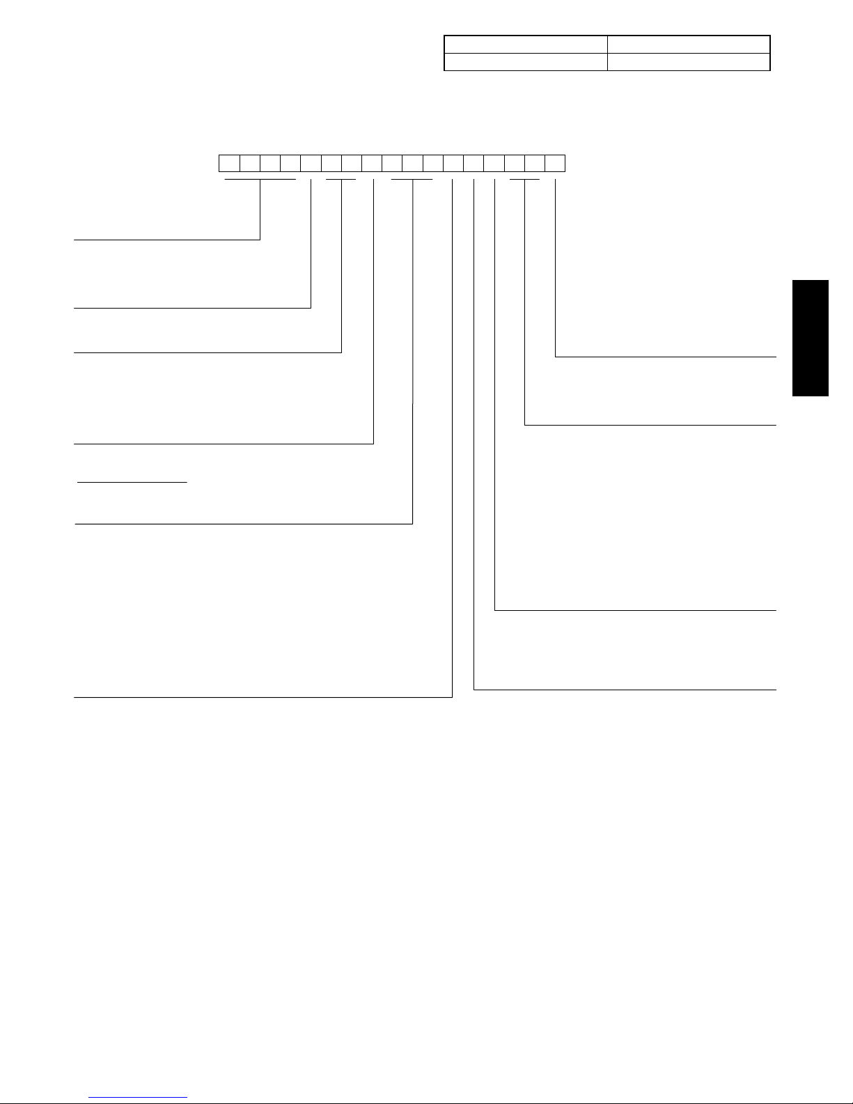
1234567891011 12
581JE14D240A3A0AA
Model
581J = High Efficiency Gas Heat
Packaged Rooftop Unit
Voltage
E = 460-3-60
P = 208/230-3-60
T = 575-3-60
Cooling Tons
14 - 12.5 ton
Refirg. System/Gas Heat Options
D = Two Stage Cooling Models
F = Two Stage Cooling Models and
Stainless Steel Gas Heat Exchanger
K = Two Stage Cooling Models and Perfect Humidity
M = Two Stage Cooling Models/SS HX Heat and Perfect Humidity
Heat Level
Standard/Stainless Steel
150 = 150,000
180 = 180,000
240 = 240,000
Coil Options (Outdoor – Indoor – Hail Guard)
A = Al/Cu – Al/Cu
B = Precoat Al/Cu – Al/Cu
C = E-coat Al/Cu – Al/Cu
D = E-coat Al/Cu – E-Coat Al/Cu
E = Cu/Cu – Al/Cu
F = Cu/Cu – Cu/Cu
M = Al/Cu – Al/Cu – Louvered Hail Guards
N = Precoat Al/Cu – Al/Cu – Louvered Hail Guards
P = E-coat Al/Cu – Al/Cu – Louvered Hail Guards
Q = E-coat Al/Cu – E-coat Al/Cu – Louvered Hail Guards
R = Cu/Cu – Al/Cu – Louvered Hail Guards
S = Cu/Cu – Cu/Cu – Louvered Hail Guards
TM
Fig. 1 -- 581J 14 Model Number Nomenclature (Example)
13
14 15 16 17
Packaging and 2-Speed Indoor Fan Motor
A = Standard Packaging, electro mech. controls
that require W7212 EconoMi$er IV
B = LTL Packaging, electro mech. controls
that require W7212 EconoMi$er IV
C = Standard Packaging, electro mech. controls
that require W7220 EconoMi$er X
D = Standard Packaging and 2-speed Indoor Fan
Motor (VFD) Controller
E = LTL Packaging and 2-speed Indoor Fan
Motor (VFD) Controller
F = LTL Packaging, electro mech. controls that
require W7220 EconoMi$er X
Factory Installed Options
0A = None
NOTE: See the 581J 3 to 15 ton Price Pages for a
complete list of factory installed options.
Outdoor Air Options
A = None
B = Temperature Econo w/ Barometric Relief
and W7212 Econo Controller
E = Temperature Econo w/ Barometric Relief, CO2
and W7212 Econo Controller
H = Enthalpy Econo w/ Barometric Relief
and W7212 Econo Controller
L = Enthalpy Econo w/ Barometric Relief, CO2
and W7212 Econo Controller
Q = Motorized 2 Position Damper w/ Barometric Relief
U = Temperature Ultra Low Leak Econo
w/ Barometric Relief
W = Enthalpy Ultra Low Leak Econo w/ Barometric Relief
Indoor Fan Options
1 = Standard Static Option – Belt Drive
2 = Medium Static Option – Belt Drive
3 = High Static Option – Belt Drive
C = High Static Option with High Efficiency Motor – Belt Drive
581J*14
C150074
3
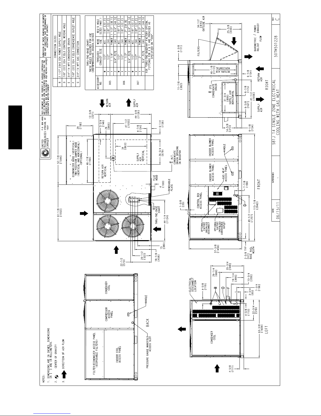
581J*14
Fig. 2 -- Unit Dimensional Drawing – 14 Size Unit
C11338
4
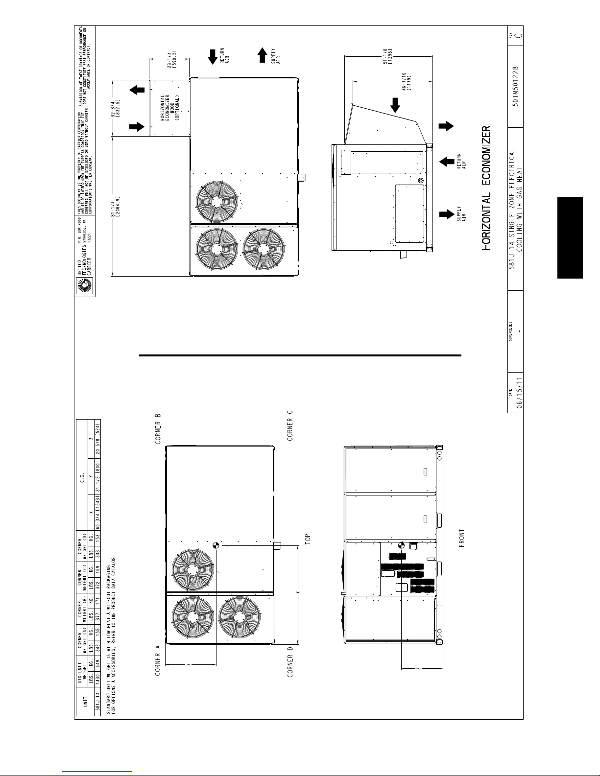
581J*14
Fig. 2 -- Unit Dimensional Drawing – 14 Size Unit (cont.)
C11339
5
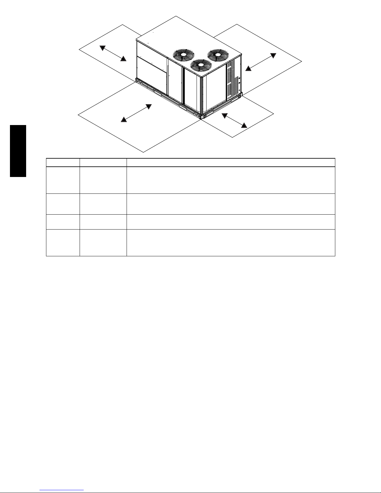
C
D
B
A
581J*14
LOCATION DIMENSION CONDITION
48---in (1219 mm)
A
B
C
D
NOTE: Unit not designed to have overhead obstruction. Contact Application Engineering for guidance on any application
18---in (457 mm)
18---in (457) mm
12---in (305 mm)
42---in (1067 mm)
36---in (914 mm)
Special
36---in (914 mm)
18---in (457 mm)
48---in (1219 mm)
42---in (1067 mm)
36---in (914 mm)
Special
planning overhead obstruction or for vertical clearances.
Unit disconnect is mounted on panel
No disconnect, convenience outlet option
Recommended service clearance
Minimum clearance
Surface behind servicer is grounded (e.g., metal, masonry wall)
Surface behind servicer is electrically non---conductive (e.g., wood, fiberglass)
Check sources of flue products within 10---ft of unit fresh air intake hood
Side condensate drain is used
Minimum clearance
No flue discharge accessory installed, surface is combustible material
Surface behind servicer is grounded (e.g., metal, masonry wall, another unit)
Surface behind servicer is electrically non---conductive (e.g., wood, fiberglass)
Check for adjacent uni ts or building fresh air intakes within 10- --ft (3 m ) of this unit’s flue outlet
Fig. 3 -- Service Clearance Dimensional Drawing
INSTALLATION
Jobsite Survey
Complete the following checks before installation.
1. Consult local building codes and the NEC (National
Electrical Code) ANSI/NFPA 70 for special installation requirements.
2. Determine unit location (from project plans) or select
unit location.
3. Check for possible overhead obstructions which may
interfere with unit lifting or rigging.
Step 1 — Plan for Unit Location
Select a location for the unit and its support system (curb
or other) that provides for at least the minimum clearances
required for safety. This includes the clearance to
combustible surfaces, unit performance and service access
below, around and above unit as specified in unit
drawings. See Fig. 3.
NOTE: Consider also the effect of adjacent units.
C12322
Unit may be installed directly on wood flooring or on Class
A, B, or C roof--covering material when roof curb is used
Do not install unit in an indoor location. Do not locate air
inlets near exhaust vents, relief valves, or other sources of
contaminated air.
Although unit is weatherproof, avoid locations that permit
water from higher level runoff and overhangs to fall onto
the unit.
Select a unit mounting system that provides adequate
height to allow installation of condensate trap per
requirements. Refer to Step 11 — Install External
Condensate Trap and Line – for required trap dimensions.
Roof Mount —
Check building codes for weight distribution
requirements. Unit operating weight is shown in Table 1.
6

Table 1 – Operating Weights
581J*14
COMPONENT UNITS LB (KG)
Base Unit 1430 (649)
Economizer
Vertical 100 (45)
Horizontal 115 (52)
Perfect Humidity™ System 62 (28)
Powered Outlet 32 (15)
Curb
14---in/356 mm 180 (82)
24---in/610 mm 235 (107)
Step 2 — Plan for Sequence of Unit Installation
The support method used for this unit will dictate different
sequences for the steps of unit installation. For example,
on curb--mounted units, some accessories must be
installed on the unit before the unit is placed on the curb.
Review the following for recommended sequences for
installation steps.
Curb--mounted installation —
Install curb
Install field--fabricated ductwork inside curb
Install accessory thru--base service connection package
(affects curb and unit) (refer to accessory installation
instructions for details)
Prepare bottom condensate drain connection to suit
planned condensate line routing (refer to Step 9 for
details)
Rig and place unit
Install outdoor air hood
Install condensate line trap and piping
Make electrical connections
Install other accessories
Pad--mounted installation —
Prepare pad and unit supports
Check and tighten the bottom condensate drain
connection plug
Rig and place unit
Convert unit to side duct connection arrangement
Install field--fabricated ductwork at unit duct openings
Install outdoor air hood
Install condensate line trap and piping
Make electrical connections
Install other accessories
Frame--mounted installation —
Frame--mounted applications generally follow the
sequence for a curb installation. Adapt as required to
suit specific installation plan.
Step 3 — Inspect Unit
Inspect unit for transportation damage. File any claim
with transportation agency.
Confirm before installation of unit that voltage, amperage
and circuit protection requirements listed on unit data
plate agree with power supply provided.
On units with hinged panel option, check to be sure all
latches are snug and in closed position.
Locate the carton containing the outside air hood parts;
see Figs. 11 & 12. Do not remove carton until unit has
been rigged and located in final position.
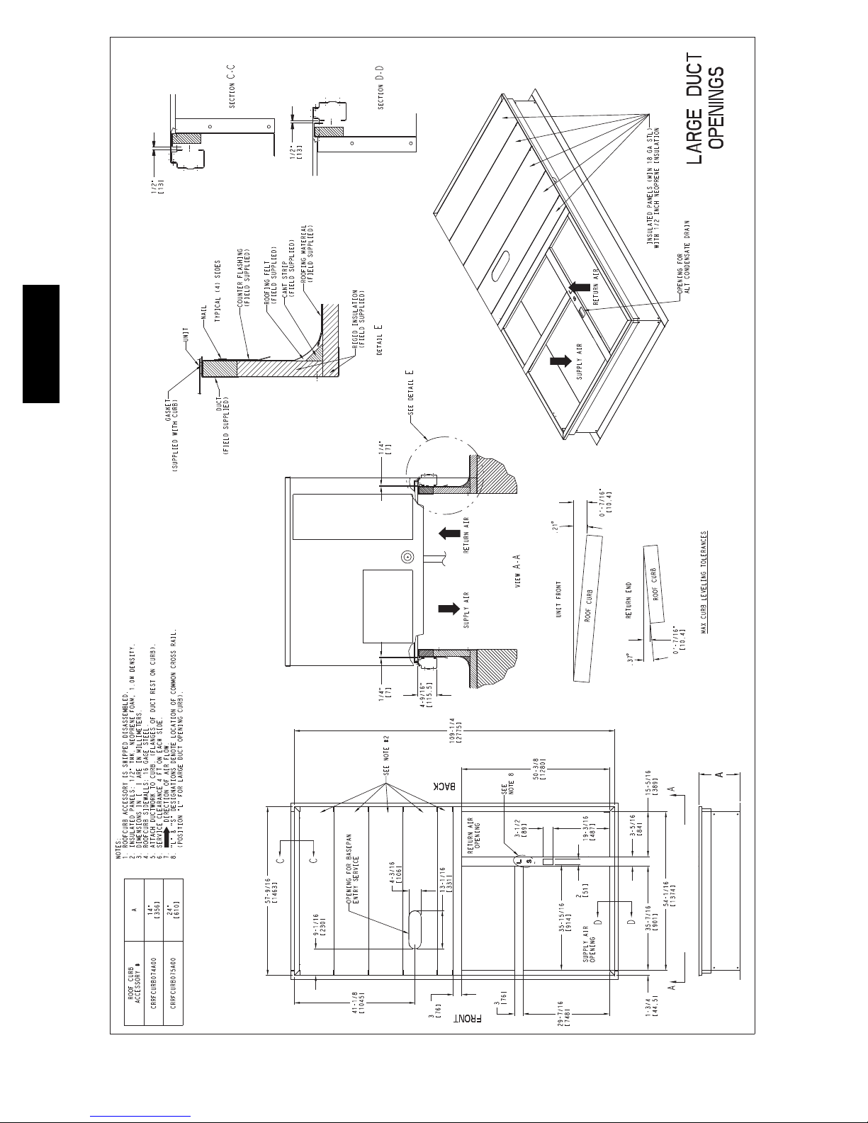
Step 4 — Provide Unit Support
Roof Curb Mount —
Accessory roof curb details and dimensions are shown in
Fig. 4. Assemble and install accessory roof curb in
accordance with instructions shipped with the curb.
NOTE: The gasketing of the unit to the roof curb is
critical for a watertight seal. Install gasket supplied with
the roof curb as shown in Fig. 4. Improperly applied
gasket can also result in air leaks and poor unit
performance.
581J*14
7
581J*14
Fig. 4 -- Roof Curb Details
C10772
8
Curb should be level. This is necessary for unit drain to
function properly. Unit leveling tolerances are show in
Fig. 5. Refer to Accessory Roof Curb Installation
Instructions for additional information as required.
C
A
B
MAXIMUM ALLOWABLE
DIFFERENCE IN. (MM)
A-B
0.5” (13)
B-C
1.0” (25)
A-C
1.0” (25)
C10001
Fig. 5 -- Unit Leveling Tolerances
Step 5 — Field Fabricate Ductwork
NOTE: Cabinet return-air static pressure (a negative
condition) shall not exceed 0.35 in. wg (87 Pa) with
economizer or 0.45 in. wg (112 Pa) without economizer.
For vertical ducted applications, secure all ducts to roof curb
and building structure. Do not connect ductwork to unit.
Fabricate supply ductwork so that the cross sectional
dimensions are equal to or greater than the unit supply
duct opening dimensions for the first 18 in. (458 mm) of
duct length from the unit basepan.
Insulate and weatherproof all external ductwork, joints,
and roof openings with counter flashing and mastic in
accordance with applicable codes.
Ducts passing through unconditioned spaces must be
insulated and covered with a vapor barrier.
Install insulation, cant strips, roofing felt, and counter
flashing as shown. Ductwork must be attached to curb and
not to the unit.
IMPORTANT:
If the unit’s gas connection and/or electric and control
wiring is to be routed through the basepan and the unit
is equipped with the factory--installed Thru--the--Base
service option see the following sections:
S Factory--Option Thru--Base Connections
(Gas Connection) on page 11
S Factory--Option Thru--Base Connections
(Electrical Connections) on page 18
If using the field--installed Thru--the--Base accessory
follow the instructions provided with the accessory kit.
NOTE: If gas and/or electrical connections are not
going to occur at this time, tape or otherwise cover the
fittings so that moisture does not get into the building or
conduit in the interim.
Slab Mount (Horizontal Units Only) —
Provide a level concrete slab that extends a minimum of
6 in. (150 mm) beyond unit cabinet. Install a gravel apron
in front of condenser coil air inlet to prevent grass and
foliage from obstructing airflow.
NOTE: Horizontal units may be installed on a roof curb
if required.
Alternate Unit Support
(InLieuofCurborSlabMount)—
A non--combustible sleeper rail can be used in the unit curb
support area. If sleeper rails cannot be used, support the long
sides of the unit with a minimum of 3 equally spaced 4--in. x
4--in. (102 mm x 102 mm) pads on each side.
If a plenum return is used on a vertical unit, the return
should be ducted through the roof deck to comply with
applicable fire codes.
!
CAUTION
PROPERTY DAMAGE HAZARD
Failure to follow this caution may result in damage
to roofing materials.
Membrane roofs can be cut by sharp sheet metal
edges. Be careful when placing any sheet metal parts
on such roof.
Step 6 — Rig and Place Unit
When the unit is ready to be rigged and no longer will be
lifted by a fork truck, the wood protector under the basepan
must be removed. Remove 4 screws from each base rail.
Wood protector will drop to the ground. See instructions on
the unit base rails.
Keep unit upright and do not drop. Spreader bars are
required. Rollers may be used to move unit across a roof.
Level by using unit frame as a reference. See Table 1 and
Fig. 6 for additional information.
Lifting holes are provided in base rails as shown in Fig. 6.
Refer to rigging instructions on unit.
!
UNIT DAMAGE HAZARD
Failure to follow this caution may result in
equipment damage.
All panels must be in place when rigging. Unit is not
designed for handling by fork truck.
CAUTION
581J*14
Before setting the unit onto the curb, recheck gasketing on
curb.
9
“B”
914 - 1371
( 36” - 54” )
“C”
PLACE ALL SEAL STRIP IN PLACE BEFORE PLACING
UNIT ON ROOF CURB.
“A”
SEE DETAIL “A”
MAX WEIGHT
LB KG IN MM IN MM IN MM
581J*14
UNIT
581J*14 2215 1009 116.0 2945 62.5 1590 59.5 1510
NOTES:
1. SPREADER BARS REQUIRED — Top damage will occur if spreader bars are not used.
2. Dimensions in ( ) are in millimeters.
3. Hook rigging shackles through holes in base rail, as shown in detail “ A.” Holes in base rails are centered around
the unit center of gravity. Use wooden top to prevent rigging s traps from damaging unit .
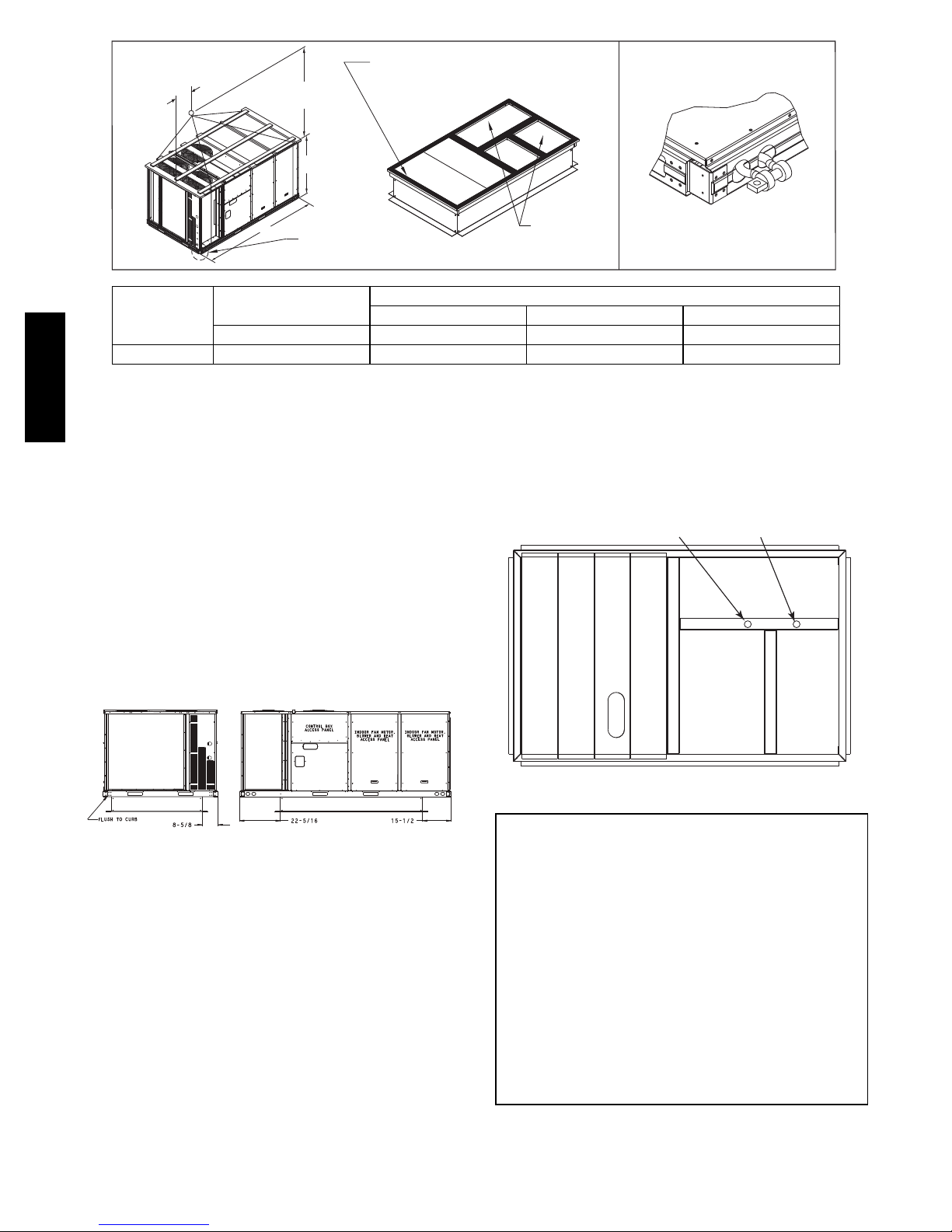
PositioningonCurb—
For full perimeter curbs CRRFCURB074A00 and 075A00,
the clearance between the roof curb and the front and rear
1
base rails should be
the curb and the end base rails should be
/4in (6.4 mm). The clearance between
1
/2in (13 mm). For
retrofit applications with curbs CRRFCURB003A01 and
4A01, the unit should be position as shown in Fig. 7.
5
Maintain the 15.5 in (394 mm) and 8
5
clearances and allow the 22
/16in (567 mm) dimension to
/8in (220 mm)
float if necessary.
DUCT END
A B C
Fig. 6 -- Rigging Details
DIMENSIONS
Original
Position
DETAIL “A”
C10774
New Position
(moved 12.5 in.)
Fig. 7 -- Retrofit Installation Dimensions
If the alternative condensate drain location through the
bottom of the unit is used in conjunction with a retrofit
curb, the hole in the curb must be moved 12.5 in (320
mm) towards the end of the unit. (See Fig. 8.)
Although unit is weatherproof, guard against water from
higher level runoff and overhangs.
Remove all shipping materials and top skid. Remove extra
center post from the condenser end of the unit so that the
condenser end of the unit matches Figs. 27 and 28.
Recycle or dispose of all shipping materials.
C10003
C10904
Fig. 8 -- Alternative Condensate Drain Hole Positions
IMPORTANT:
If the unit has the factory--installed Thru--the--Base
option, make sure to complete installation of the option
before placing the unit on the roof curb.
See the following sections:
S Factory--Option Thru--Base Connections
(Gas Connection) on page 11
S Factory--Option Thru--Base Connections
(Electrical Connections) on page 18
NOTE: If gas and/or electrical connections are not
going to occur at this time, tape or otherwise cover the
fittings so that moisture does not get into the building or
conduit in the interim.
10
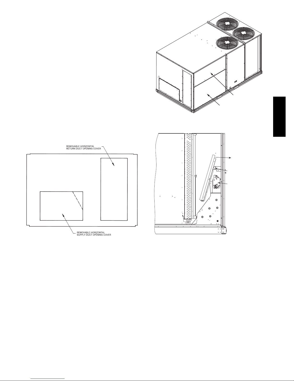
Step 7 — Convert to Horizontal and Connect
Ductwork (when required)
Unit is shipped in the vertical duct configuration. Unit
without factory--installed economizer or return air smoke
detector option may be field--converted to horizontal
ducted configuration using accessory
CRDUCTCV002A00. To convert to horizontal
configuration, remove screws from side duct opening
covers and remove covers.
Discard the supply duct cover. Install accessory
CRDUCTCV002A00 to cover the vertical supply duct
opening. Use the return duct cover removed from the end
panel to cover the vertical return duct opening.
Field--supplied flanges should be attached to horizontal
duct openings and all ductwork should be secured to the
flanges. Insulate and weatherproof all external ductwork,
joints, and roof or building openings with counter flashing
and mastic in accordance with applicable codes.
Do not cover or obscure visibility to the unit’s informative
data plate when insulating horizontal ductwork.
FILTER ACCESS PANEL
INDOOR COIL ACCESS PANEL
Fig. 10 -- Typical Access Panel Locations
Remove Hood Parts
Cut Plastic Ties
(2) Places
Economizer
C10004
581J*14
Fig. 9 -- Horizontal Conversion Panels
Step 8 — Install Outside Air Hood
Economizer Hood Removal and Setup -Factory Option —
1. The hood is shipped in knock--down form and located
in the return air compartment. It is attached to the
economizer using two plastic tie--wraps.
2. To gain access to the hood, remove the filter access
panel. (See Fig. 10.)
3. Locate and cut the (2) plastic tie--wraps, being careful
to not damage any wiring. (See Fig. 11.)
4. Carefully lift the hood assembly through the filter
access opening and assemble per the steps outlined in
Economizer Hood and Two–Position Hood on page 10.
C06108
C10005
Fig. 11 -- Economizer Hood Package Location
Two Position Damper Hood Removal and Setup -Factory Option —
1. The hood is shipped in knock--down form and
assembled to a metal support tray using plastic stretch
wrap. Located in the return air compartment, the
assembly’s metal tray is attached to the basepan and
also attached to the damper using two plastic
tie--wraps.
2. To gain access to the hood, remove the filter access
panel. (See Fig. 10.)
3. Locate the (2) screws holding the metal tray to the
basepan and remove. In order to remove the screws, it
may be necessary to remove the panel underneath the
two--position damper. Remove the two screws. Locate
and cut the (2) plastic tie--wraps securing the
assembly to the damper. (See Fig. 12.) Be careful to
not damage any wiring or cut tie--wraps securing any
wiring.
11
4. Carefully lift the hood assembly (with metal tray)
through the filter access opening and assemble per the
steps outlined in Economizer Hood and Two–Position
Hood on page 10.
5. If removed, reattach the panel under the damper.
Hood Parts
LEFT
HOOD
SIDE
SCREW
TOP
PAN EL
INDOOR COIL
ACCESS PANEL
Plastic Tie Wrap
Qty (2)
581J*14
Screws for Metal Tray
Qty (2)
Fig. 12 -- Two--Position Damper Hood Package Location
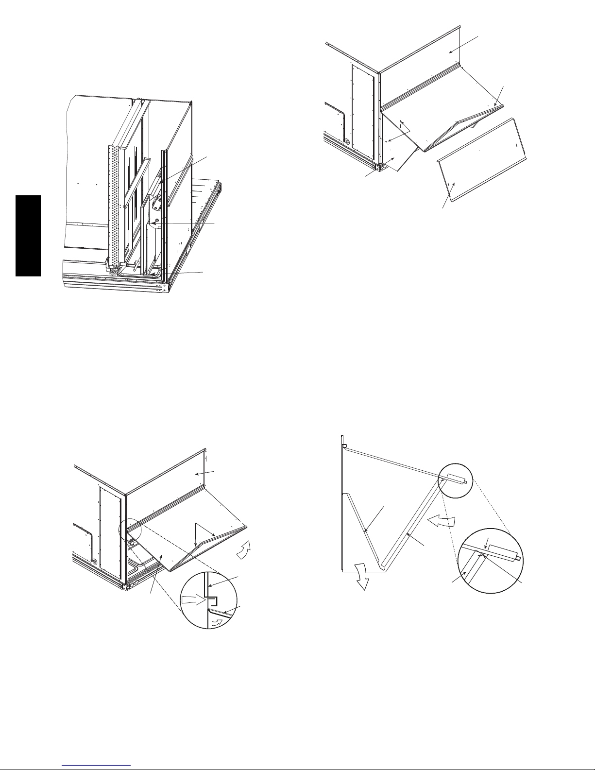
Economizer Hood and Two--Position Hood —
NOTE: If the power exhaust accessory is to be installed
on the unit, the hood shipped with the unit will not be
used and must be discarded. Save the aluminum filter for
use in the power exhaust hood assembly.
1. The indoor coil access panel will be used as the top of
the hood. If the panel is still attached to the unit, remove the screws along the sides and bottom of the
panel. See Fig. 13.
SIDE
PAN EL
C10006
HOOD DIVIDER
C10008
Fig. 14 -- Economizer Hood Construction
3. Remove the shipping tape holding the economizer
barometric relief damper in place.
4. Insert the hood divider between the hood sides. See
Fig. 14 and 15. Secure hood divider with 3 screws on
each hood side. The hood divider is also used as the
bottom filter rack for the aluminum filter.
5. Attach the post that separates the filters with the
screws provided.
6. Open the filter clips which are located underneath the
hood top. Insert the aluminum filters into the bottom
filter rack (hood divider). Push the filter into position
past the open filter clips. Close the filter clips to lock
the filters into place. See Fig. 15.
7. Install the two rain deflectors on the edge of the hood
topasshowninFig.13.
RAIN DEFLECTORS
CAULK
INDOOR
COIL
ACCESS
PAN EL
HERE
Fig. 13 -- Indoor Coil Access Panel Relocation
2. Swing out indoor coil access panel and insert the
hood sides under the panel (hood top). Be careful not
to lift the panel too far as it might fall out. Use the
screws provided to attach the hood sides to the hood
top. Use screws provided to attach the hood sides to
the unit. See Fig. 14.
TOP
PAN EL
INDOOR
COIL
ACCESS
PAN EL
C10007
BAROMETRIC
RELIEF
DIVIDER
CLEANABLE
ALUMINUM
FILTER
FILTER
OUTSIDE
AIR
HOOD
Fig. 15 -- Economizer Filter Installation
8. Caulk the ends of the joint between the unit top panel
and the hood top as shown in Fig. 13.
9. Replace the filter access panel.
12
FILTER
CLIP
C10009
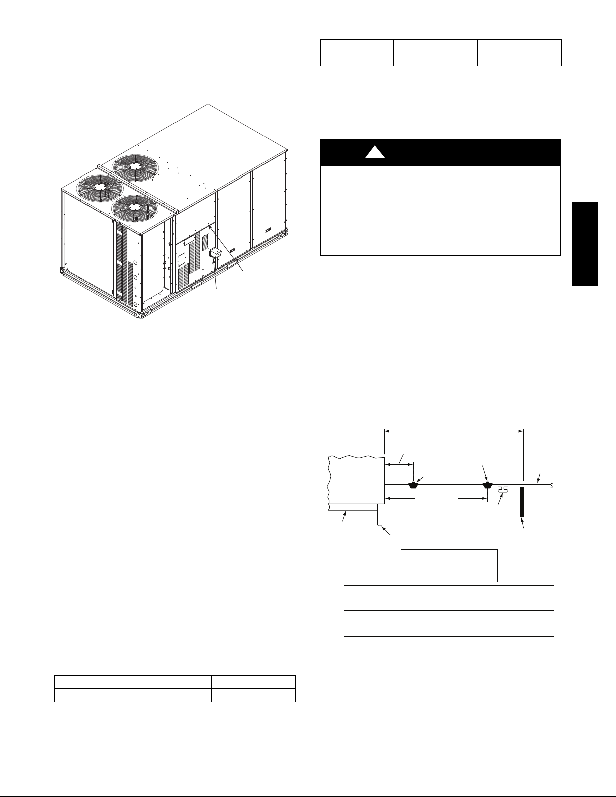
Step 9 — Install Flue Hood
R
The flue hood is shipped screwed to the basepan beside
the burner compartment access panel. Remove the panel
below the control box access panel to access the flue hood
shipping location. Using screws provided, install flue
hood and screen in location shown in Fig. 16.
Table 3 – Liquid Propane Supply Line Pressure Ranges
UNIT MIN MAX
581J*14 11.0 in. wg (2740 Pa) 13.0 in. wg (3240 Pa)
The gas supply pipe enters the unit at the burner access
panel on the front side of the unit, through the long slot at
the bottom of the access panel. The gas connection to the
3
unit is made to the
/4--in. FPT gas inlet port on the unit gas
valve.
CONTROL BOX
ACCESS PANEL
FLUE
HOOD
C10804
Fig. 16 -- Flue Hood Details
Step 10 — Install Gas Piping
Installation of the gas piping must be accordance with
local building codes and with applicable national codes.
In U.S.A., refer to NFPA 54/ANSI Z223.1 National Fuel
Gas Code (NFGC). In Canada, installation must be
accordance with the CAN/CSA B149.1 and CAN/CSA
B149.2 installation codes for gas burning appliances.
This unit is factory equipped for use with Natural Gas fuel
at elevations up to 2000 ft (610 m) above sea level. Unit
may be field converted for operation at elevations above
2000 ft (610 m) and/or for use with liquefied petroleum
fuel. See accessory kit installation instructions regarding
these accessories.
NOTE: In U.S.A. the input rating for altitudes above 2000
ft (610 m) must be derated by 4% for each 1000 ft (305 m)
above sea level. In Canada the input rating must be derated
by 10% for altitudes of 2000 ft (610 m) to 4500 ft. (1372 m)
above sea level.
For natural gas applications, gas pressure at unit gas
connection must not be less than 5 in. wg (1250 Pa) or
greater than 13 in. wg (3240 Pa) while the unit is operating.
For liquified petroleum applications, the gas pressure must
not be less than 11 in. wg (2740 Pa) or greater than 13 in.
wg (3240 Pa) at the unit connection.
Table 2 – Natural Gas Supply Line Pressure Ranges
UNIT MIN MAX
581J*14 5.0 in. wg (1250 Pa) 13.0 in. wg (3240 Pa)
!
CAUTION
EQUIPMENT DAMAGE HAZARD
Failure to follow this caution may result in damage
to equipment.
When connecting the gas line to the unit gas valve,
the installer MUST use a backup wrench to prevent
damage to the valve.
Install a gas supply line that runs to the unit heating
section. Refer to the NFPA 54/NFGC or equivalent code
for gas pipe sizing data. Size the gas supply line to allow
for a maximum pressure drop of 0.5--in wg (124 Pa)
between gas regulator source and unit gas valve
connection when unit is operating at high--fire flow rate.
The gas supply line can approach the unit in three ways:
horizontally from outside the unit (across the roof),
thru--curb/under unit basepan (accessory kit required) or
through unit basepan (factory--option or accessory kit
required). Consult accessory kit installation instructions
for details on these installation methods. Observe
clearance to gas line components per Fig. 17.
X
9” MINIMUM CLEARANCE
BASE UNIT
BASE RAIL
FOR PANEL REMOVAL
MANUAL GAS
SHUTOFF VALVE
48” MINIMUM
ROOF
CURB
NFGC – National Fuel Gas Code
Field supplied.
*
NOTE: Follow all local codes.
STEEL PIPE
NOMINAL DIAMETER
(in.)
1
/
2
3
/
or 1
4
1
1
/
or larger
4
LEGEND
GAS
REGULATOR
*
DRIP LEG
PER NFGC
FABRICATED
SPACINGOFSUPPORTS
X DIMENSION
(ft)
6
8
10
*
*
FIELD-
SUPPORT
FROM
GAS
METE
*
C11121
Fig. 17 -- Gas Piping Guide
581J*14
13
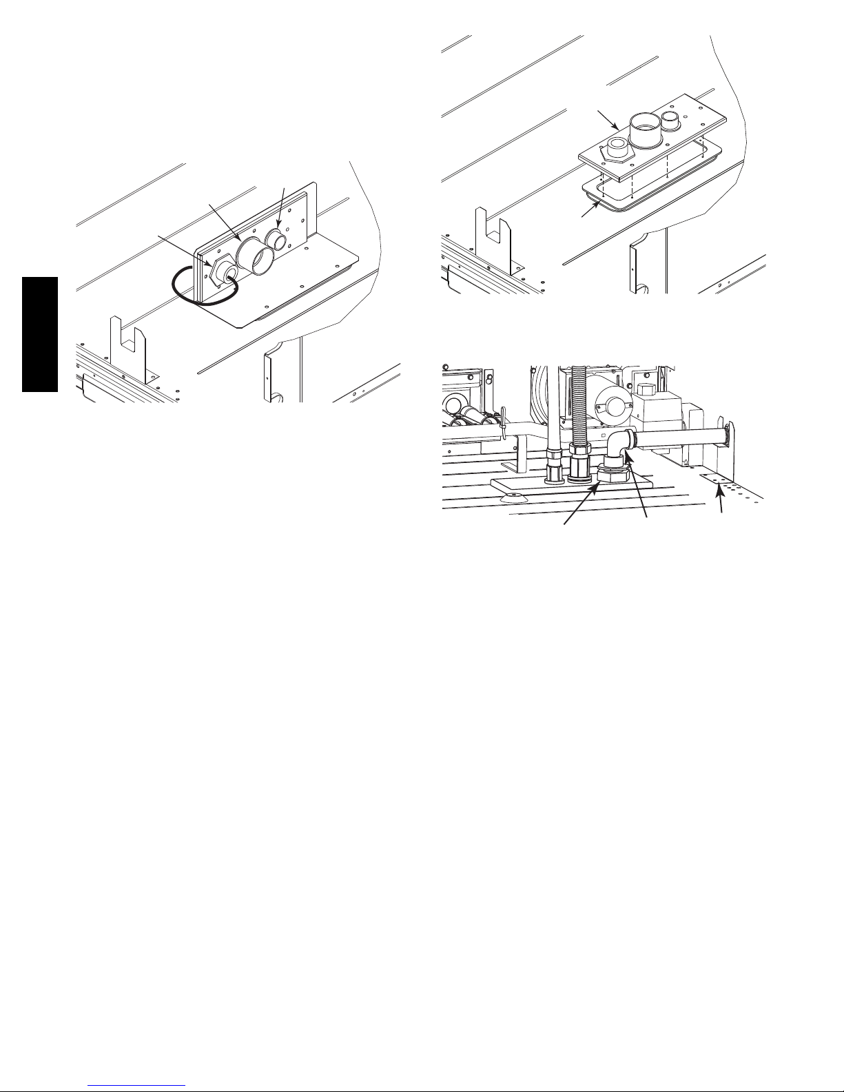
Factory--Option Thru--Base Connections
(Gas Connection) —
3
This serviceconnection kit consists of a
1
fitting (stainless steel), a
1
and a 1
/2--in electrical bulkhead connector, connected to an
/2--in electrical bulkhead connector
/4--in NPTgasadapter
“L” bracket covering the embossed (raised) section of the unit
basepan in the condenser section. See Fig. 18.
1
/2” ELECTRICAL
BULKHEAD
CONNECTOR
3
/4” NPT GAS
ADAPTER
FITTING
11/2” ELECTRICAL
BULKHEAD
CONNECTOR
581J*14
Fig. 18 -- Thru--the--Base Option, Shipping Position
C10905
CONNECTOR
PLATE
ASSEMBLY
GASKET
C10906
Fig. 19 -- Completing Installation of Thru--the--Base
Option
1. Remove the “L” bracket assembly from the unit (see
Fig. 18).
2. Cut and discard the wire tie on the gas fitting. Hand
tighten the fitting if it has loosened in transit.
3. Remove connector plate assembly from the “L”
bracket and discard the “L” bracket, but retain the
washer head screws and the gasket (located between
the “L” bracket and the connector plate assembly
NOTE: Take care not to damage the gasket, as it is
reused in the following step.
4. Place the gasket over the embossed area in the
basepan, aligning the holes in the gasket to the holes
in the basepan. See Fig. 19.
5. Install the connector plate assembly to the basepan
using 8 of the washer head screws.
NOTE: If gas and/or electrical connections are not going to
occur at this time, tape or otherwise cover the fittings so that
moisture doesnot get into the building or conduit in theinterim.
The thru--base gas connector has male and female threads.
The male threads protrude above the basepan of the unit;
the female threads protrude below the basepan.
Check tightness of connector lock nuts before connecting
gas piping.
3
Install a
fitting. Attach a
/4--in NPT street elbow on the thru--base gas
3
/4--in pipe nipple with minimum length
of 16--in (406 mm) (field--supplied) to the street elbow
and extend it through the access panel at the gas support
bracket. (See Fig. 20.)
THRU-BASE
GAS FITTING
3
/4-in NPT
STREET
ELBOW
GAS
SUPPORT
BRACKET
C10806
Fig. 20 -- Gas Line Piping
Other hardware required to complete the installation of
the gas supply line will include a manual shutoff valve, a
sediment trap (drip leg) and a ground--joint union. A
pressure regulator valve may also be required (to convert
gas pressure from pounds to inches of pressure). The
manual shutoff valve must be located within 6--ft (1.83 m)
of the unit. The union, located in the final leg entering the
unit, must be located at least 9--in (230 mm) away from
the access panel to permit the panel to be removed for
service. If a regulator valve is installed, it must be located
a minimum of 4--ft (1220 mm) away from the unit’s flue
outlet. Some municipal codes require that the manual
shutoff valve be located upstream of the sediment trap.
See Fig. 21 and 22 for typical piping arrangements for gas
piping that has been routed through the sidewall of the
curb. See Fig. 23 for typical piping arrangement when
thru--base is used. Ensure that all piping does not block
access to the unit’s main control box or limit the required
working space in front of the control box.
14
 Loading...