

Bryant 581J series Installation Instructions Manual

581J
SINGLE PACKAGE ROOFTOP
GAS HEATING/ELECTRIC COOLING UNIT
SIZES 07, 08, 09, 11, 12 WITH PURONR (R−410A) REFRIGERANT
Installation Instructions
NOTE: Read the entire instruction manual before starting
the installation
TABLE OF CONTENTS
SAFETY CONSIDERATIONS 2....................
Rated Indoor Airflow (cfm) 3.....................
INSTALLATION 8...............................
Jobsite Survey 8................................
Step 1 − Plan for Unit Location 8..................
Roof Mount 9...............................
Step 2 − Plan for Sequence of Unit Installation 9......
Curb−Mounted Installation 9...................
Pad−Mounted Installation 9....................
Frame−Mounted Installation 9..................
Step 3 − Inspect Unit 9...........................
Step 4 − Provide Unit Support 9...................
Roof Curb Mount 9..........................
Slab Mount (Horizontal Units Only) 11..........
Alternate Unit Support
(In Lieu of Curb or Slab Mount) 11.............
Step 5 − Field Fabricate Ductwork 11...............
Step 6 − Rig and Place Unit 11....................
Positioning on Curb 12.......................
Step 7 − Convert to Horizontal & Connect Ductwork 12.
Step 8 − Install Outside Air Hood 13...............
Economizer and Two Position Damper Hood
Package Removal and Setup — Factory Option 13..
Economizer Hood and Two−Position Hood 13.....
Step 9 − Install Flue Hood 14.....................
Step 10 − Install Gas Piping 14....................
Factory−Option Thru−Base Connections
(Gas Connections) 15.........................
Step 11 − Install External Condensate Trap and Line 17..
Step 12 − Make Electrical Connections 17...........
Field Power Supply 17........................
Units with Factory−Installed
Non−Fused Disconnect 18.....................
Units without Factory−Installed
Non−Fused Disconnect 19.....................
All Units 19................................
Convenience Outlets 19.......................
Factory−Option Thru−Base Connections
(Electrical Connections) 21....................
Units without Thru−Base Connections 21.........
Field Control Wiring 21.......................
Thermostat 21...............................
Unit without Thru−Base Connection Kit 21.......
Heat Anticipator Settings 22...................
Low Ambient Control (Factory Option) 22...........
Variable Frequency Dri ve (VFD) 2−Speed Indoor Fan
Motor System (Fac t ory Opt ion) 22..................
EconoMi$er X − Ultra Low Leak Economizer
(Factory Option) 22.............................
Perfect Humidityt System Control Connections 22..
Perfect Humidity System − Space RH Controller 22..
RTU Open Controller System 24.................
Supply Air Temperature (SAT) Sensor 27.........
Outdoor Air Temperature (OAT) Sensor 27.......
EconoMi$er2 28.............................
Field Connections 28..........................
Space Temperature (SPT) Sensors 28............
Indoor Air Quality (CO2) Sensor 29.............
Outdoor Air Quality Sensor 29.................
Space Humidity Sensor or Humidistat 30.........
Smoke Detector/Fire Shutdown (FSD) 31.........
Connecting Discrete Inputs 31..................
Communication Wiring − Protocols 32............
General 32.................................
Local Access 33..............................
RTU Open Controller Troubleshooting 33........
Outdoor Air Enthalpy Control 34.................
Differential Enthalpy Control 34................
Return Air Enthalpy Sensor 34.................
Smoke Detectors 35...........................
Step 13 − Adjust Factory−Installed Options 41........
Step 14 − Install Accessories 41...................
START−UP CHECKLIST 43.......................
SAFETY CONSIDERATIONS
Improper installation, adjustment, alteration, service,
maintenance, or use can cause explosion, fire, electrical
shock or other conditions which may cause personal
injury or property damage. Consult a qualified installer,
service agency, or your distributor or branch for
information or assistance. The qualified installer or
agency must use factory−authorized kits or accessories
when modifying this product. Refer to the individual
instructions packaged with the kits or accessories when
installing.
!
WARNING
ELECTRICAL SHOCK HAZARD
Failure to follow this warning could cause personal
injury or death.
Before performing service or maintenance operations
on unit, always turn off main power switch to unit and
install lock(s) and lockout tag(s). Unit may have more
than one power switch.
Follow all safety codes. Wear safety glasses and work
gloves. Use quenching cloths for brazing operations and
have a fire extinguisher available. Read these instructions
thoroughly and follow all warnings or cautions attached to
the unit. Consult local building codes and appropriate
national electrical codes (in USA, ANSI/NFPA70,
National Electrical Code (NEC); in Canada, CSA C22.1)
581J
for special requirements.
It is important to recognize safety information. This is the
safety−alert symbol . When you see this symbol on the
unit and in instructions or manuals, be alert to the
potential for personal injury.
Understand the signal words DANGER, WARNING,
CAUTION, and NOTE. These words are used with the
safety−alert symbol. DANGER identifies the most serious
hazards which will result in severe personal injury or
death. WARNING signifies hazards which could result in
personal injury or death. CAUTION is used to identify
unsafe practices, which may result in minor personal
injury or product and property damage. NOTE is used to
highlight suggestions which will result in enhanced
installation, reliability, or operation.
!
WARNING
UNIT OPERATION AND SAFETY HAZARD
Failure to follow this warning could cause personal
injury, death and/or equipment damage.
Puronr (R−410A) refrigerant systems operate at
higher pressures than standard R−22 systems. Do not
use R−22 service equipment or components on Puron
refrigerant equipment.
!
WARNING
PERSONAL INJURY AND ENVIRONMENTAL
HAZARD
Failure to follow this warning could cause personal
injury or death.
Relieve pressure and recover all refrigerant before
system repair or final unit disposal.
Ware safety glasses and gloves when handling
refrigerants. Keep torches and other ignition sources
away from refrigerants and oils.
!
WARNING
FIRE, EXPLOSION HAZARD
Failure to follow this warning could result in personal
injury or death.
Disconnect gas piping from unit when leak testing at
pressure greater than 0.5 psig (3450 Pa). Pressures
greater than 0.5 psig (3450 Pa) will cause gas valve
damage resulting in hazardous condition. If gas valve
is subjected to pressure greater than 0.5 psig (3450
Pa), it must be replaced before use. When pressure
testing field−supplied gas piping at pressures of 0.5
psig (3450 Pa) or less, a unit connected to such piping
must be isolated by closing the manual gas valve.
!
CUT HAZARD
Failure to follow this caution may result in personal
injury.
Sheet metal parts may have sharp edges or burrs. Use
care and wear appropriate protective clothing, safety
glasses and gloves when handling parts and servicing
air−conditioning equipment.
CAUTION
2
Rated Indoor Airflow (cfm)
The table to the right lists the rated indoor airflow used
for the AHRI efficiency rating for the units covered in this
document.
Model Number Full Load Airflow (cfm)
581J*07A/C/G/J 2400
581J*07D/F/K/M 2400
581J*08D/F/K/M 3000
581J*09D/F/K/M 3000
581J*11D/F/K/M 3000
581J*12D/F/K/M 3000
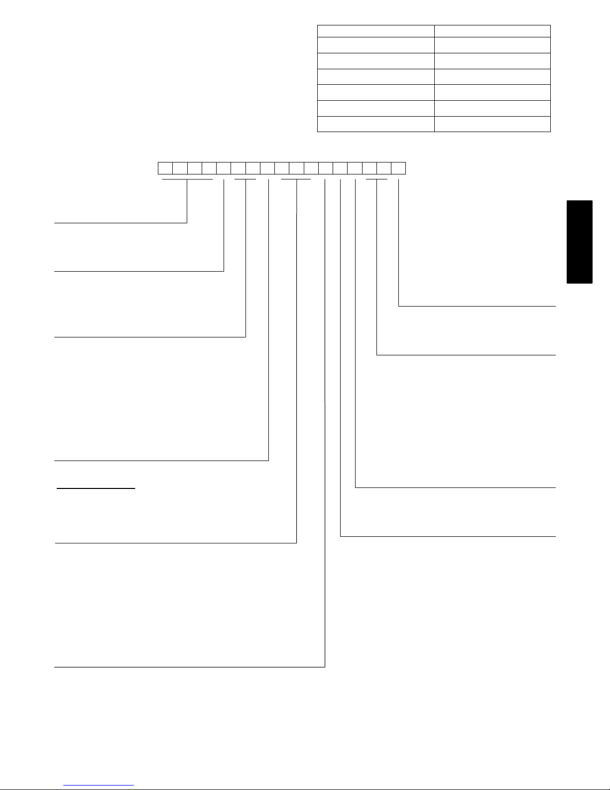
1234567891011 12
581JE12D150A3A0AA
Model
581J = High Efficiency Gas Heat
Packaged Rooftop Unit
Voltage
E = 460-3-60
P = 208/230-3-60
T = 575-3-60
Cooling Tons
07 - 6 ton
08 - 7.5 ton
09 - 8.5 ton
11 - 10 ton (12.0 EER)
12 - 10 ton (11.5 EER)
Refrigerant System/Gas Heat Options
A = Standard One Stage Cooling Models/Natural Gas Heat
C = Standard One Stage Cooling Models/Stainless Steel
Gas Heat Exchanger
D = Two Stage Cooling Models
F = Two Stage Cooling Models and
Stainless Steel Gas Heat Exchanger
G = Standard One Stage Cooling Models and Perfect Humidity
J = Standard One Stage Cooling Models/SS HX Heat and
Perfect Humidity
K = Two Stage Cooling Models and Perfect Humidity
M = Two Stage Cooling Models/Stainless Steel Gas
Heat Exchanger and Perfect Humidity
Heat Level
Standard/Stainless Steel
072 = 72,000
125 = 125,000
150 = 150,000
180 = 180,000
224 = 224,000
250 = 250,000
13
14 15 16 17
Packaging and 2-Speed Indoor Fan Motor
A = Standard Packaging, electro-mechanical
controls that require W7212 EconoMi$er IV
B = LTL Packaging, electro-mechanical controls
that require W7212 EconoMi$er IV
C = Standard Packaging, electro-mechanical
controls that require W7220 EconoMi$er X
D = Standard Packaging and 2-speed Indoor Fan
Motor (VFD) Controller
E = LTL Packaging and 2-speed Indoor Fan
Motor (VFD) Controller
F = LTL Packaging, electro-mechanical controls
that require W7220 EconoMi$er X
Factory-Installed Options
0A = None
NOTE: See the 581J 3 to 15 ton Price Pages for a
complete list of factory-installed options.
Outdoor Air Options
A = None
B = Temperature Economizer w/ Barometric Relief
and W7212 Economizer Controller
TM
E = Temperature Economizer w/ Barometric Relief, CO
and W7212 Economizer Controller
H = Enthalpy Economizer w/ Barometric Relief
and W7212 Economizer Controller
L = Enthalpy Economizer w/ Barometric Relief, CO
and W7212 Economizer Controller
Q = Motorized 2 Position Damper w/ Barometric Relief
U = Temperature Ultra Low Leak Economizer
w/ Barometric Relief
W = Enthalpy Ultra Low Leak Economizer w/ Barometric Relief
Indoor Fan Options
1 = Standard Static Option – Belt Drive
2 = Medium Static Option – Belt Drive
3 = High Static Option – Belt Drive
2
2
581J
Coil Options (Outdoor – Indoor – Hail Guard)
A = Al/Cu – Al/Cu
B = Precoat Al/Cu – Al/Cu
C = E-coat Al/Cu – Al/Cu
D = E-coat Al/Cu – E-Coat Al/Cu
E = Cu/Cu – Al/Cu
F = Cu/Cu – Cu/Cu
M = Al/Cu – Al/Cu – Louvered Hail Guards
N = Precoat Al/Cu – Al/Cu – Louvered Hail Guards
P = E-coat Al/Cu – Al/Cu – Louvered Hail Guards
Q = E-coat Al/Cu – E-coat Al/Cu – Louvered Hail Guards
R = Cu/Cu – Al/Cu – Louvered Hail Guards
S = Cu/Cu – Cu/Cu – Louvered Hail Guards
Fig. 1 − 581J*07−12 Model Number Nomenclature (Example)
C150072
3
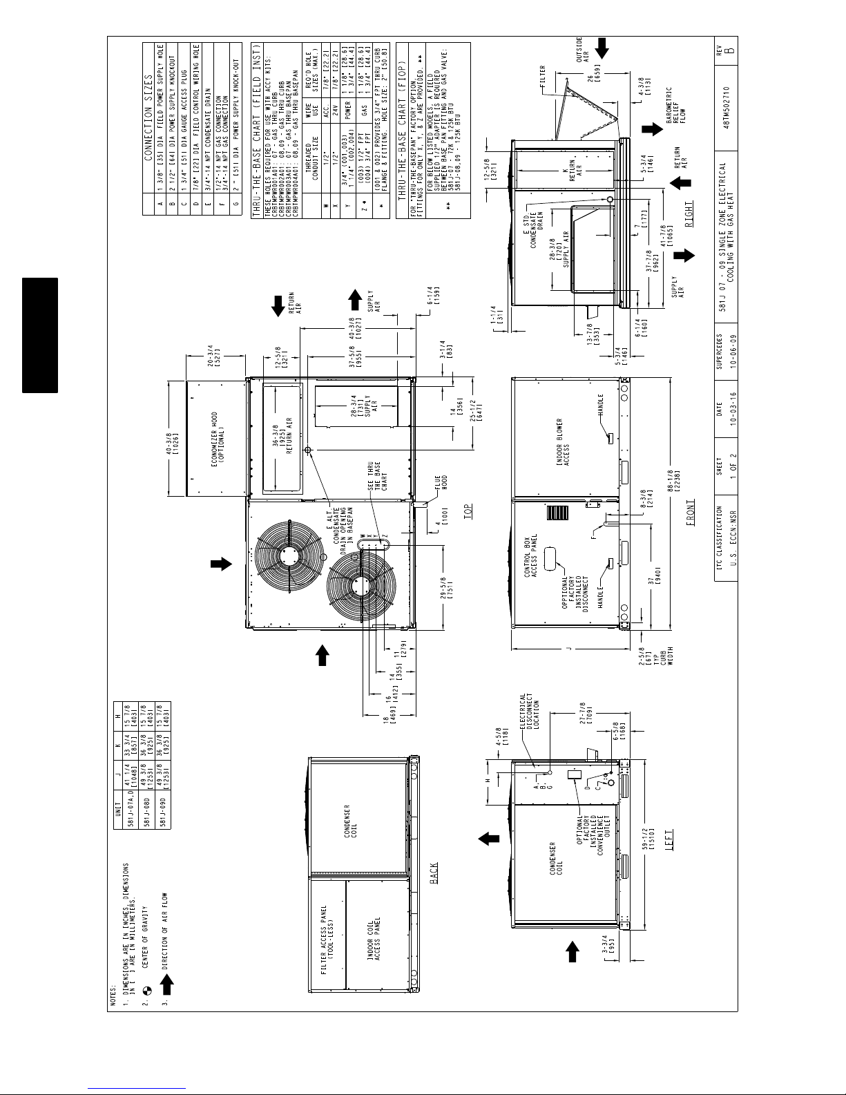
581J
Fig. 2 − Unit Dimensional Drawing — Sizes 07−09
C160140
4
581J
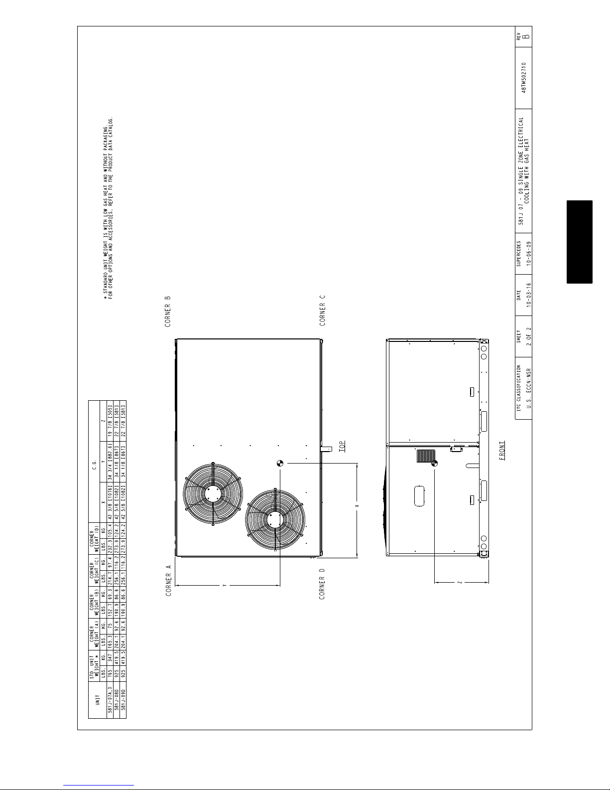
Fig. 2 − Unit Dimensional Drawing — Sizes 07−09 (cont.)
C160141
5
581J
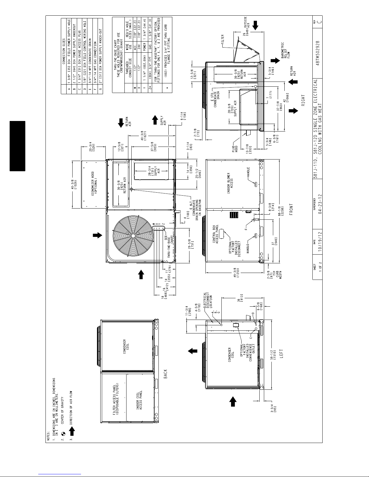
Fig. 3 − Unit Dimensional Drawing — Sizes 11 and 12
C13300A
6
581J
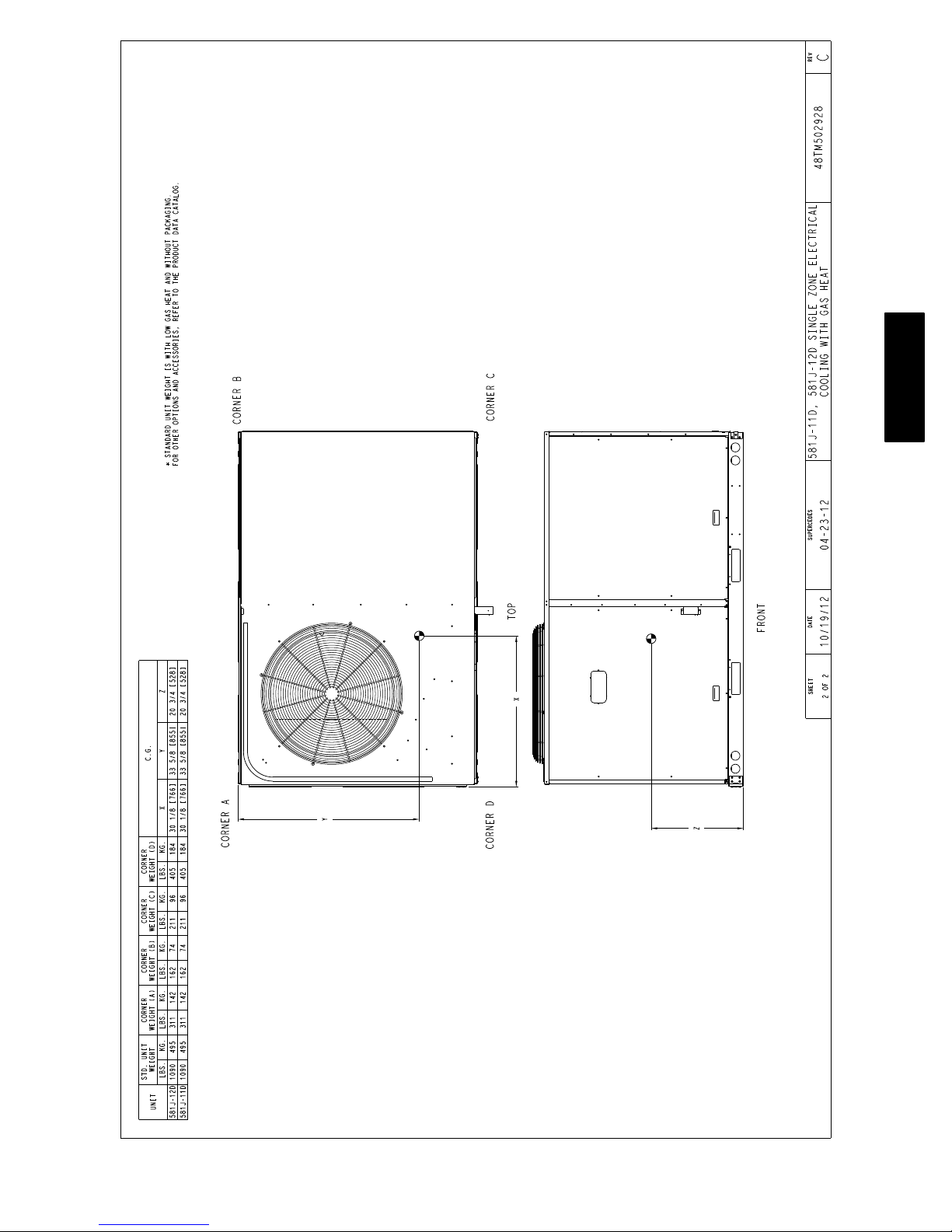
Fig. 3 − Unit Dimensional Drawing — Sizes 11 and 12 (cont.)
C13301A
7

581J
C
D
B
A
LOCATION DIMENSION CONDITION
48-in (1219 mm)
A
B
C
D
NOTE: Unit not designed to have overhead obstruction. Contact Application Engineering for guidance on any application
18-in (457 mm)
18-in (457) mm
12-in (305 mm)
42-in (1067 mm)
36-in (914 mm)
Special
36-in (914 mm)
18-in (457 mm)
48-in (1219 mm)
42-in (1067 mm)
36-in (914 mm)
Special
planning overhead obstruction or for vertical clearances.
Unit disconnect is mounted on panel
No disconnect, convenience outlet option
Recommended service clearance
Minimum clearance
Surface behind servicer is grounded (e.g., metal, masonry wall)
Surface behind servicer is electrically non-conductive (e.g., wood, fiberglass)
Check sources of flue products within 10-ft of unit fresh air intake hood
Side condensate drain is used
Minimum clearance
No flue discharge accessory installed, surface is combustible material
Surface behind servicer is grounded (e.g., metal, masonry wall, another unit)
Surface behind servicer is electrically non-conductive (e.g., wood, fiberglass)
Check for adjacent units or building fresh air intakes within 10-ft (3 m) of this unit's flue outlet
C08337
Fig. 4 − Service Clearance Dimensional Drawing — Sizes 07−12
INSTALLATION
Jobsite Survey
Complete the following checks before installation.
1. Consult local building codes and the NEC (National
Electrical Code) ANSI/NFPA 70 for special installation requirements.
2. Determine unit location (from project plans) or select
unit location.
3. Check for possible overhead obstructions which may
interfere with unit lifting or rigging.
Step 1 — Plan for Unit Location
Select a location for the unit and its support system (curb
or other) that provides for the minimum clearances
required for safety. This includes the clearance to
combustible surfaces, unit performance and service access
below, around and above unit as specified in unit
drawings. See Fig. 4.
NOTE: Consider also the effect of adjacent units.
Be sure that the unit is installed such that snow will not
block the combustion intake or flute outlet.
Unit may be installed directly on wood flooring or on
Class A, B, or C roof−covering material when roof curb is
used.
Do not install unit in an indoor location. Do not locate air
inlets near exhaust vents or other sources of contaminated
air. For proper unit operation, adequate combustion and
ventilation air must be provided in accordance with
Section 5.3 (Air for Combustion and Ventilation) of the
National Fuel Gas Code, ANSI Z223.1 (American
National Standards Institute) and NFPA (National Fire
Protection Association) 54 TIA−−54−−84−−1. In Canada,
installation must be in accordance with the CAN1−−B149
installation codes for gas burning appliances.
Although unit is weatherproof, avoid locations that permit
water from higher level runoff and overhangs to fall onto
the unit.
Locate mechanical draft system flue assembly at least 4 ft
(1.2 m) from any opening through which combustion
8

products could enter the building, and at least 4 ft (1.2 m)
from any adjacent building (or per local code). Locate the
flue assembly at least 10 ft (3.05 m) from an adjacent
unit’s fresh air intake hood if within 3 ft (0.91 m) of same
elevation (or per local code). When unit is located
adjacent to public walkways, flue assembly must be at
least 7 ft (2.1 m) above grade.
Select a unit mounting system that provides adequate
height to allow installation of condensate trap per
requirements. Refer to Step 11 — Install External
Condensate Trap and Line – for required trap dimensions.
Roof Mount —
Check building codes for weight distribution
requirements. Unit operating weight is shown in Table 1.
Step 2 — Plan for Sequence of Unit Installation
The support method used for this unit will dictate different
sequences for the steps of unit installation. For example,
on curb−mounted units, some accessories must be
installed on the unit before the unit is placed on the curb.
Review the following for recommended sequences for
installation steps.
Curb−Mounted Installation —
Install curb
Install field−fabricated ductwork inside curb
Install accessory thru−base service connection package
(affects curb and unit) (refer to accessory installation
instructions for details)
Prepare bottom condensate drain connection to suit
planned condensate line routing (refer to Step 11 for
details)
Rig and place unit
Install outdoor air hood
Install flue hood
Install gas piping
Install condensate line trap and piping
Make electrical connections
Install other accessories
Pad−Mounted Installation —
Prepare pad and unit supports
Check and tighten the bottom condensate drain
connection plug
Rig and place unit
Convert unit to side duct connection arrangement
Install field−fabricated ductwork at unit duct openings
Install outdoor air hood
Install flue hood
Install gas piping
Install condensate line trap and piping
Make electrical connections
Install other accessories
Frame−Mounted Installation —
Frame−mounted applications generally follow the
sequence for a curb installation. Adapt as required to
suit specific installation plan.
Step 3 — Inspect Unit
Inspect unit for transportation damage. File any claim
with transportation agency.
581J
Confirm before installation of unit that voltage, amperage
and circuit protection requirements listed on unit data
plate agree with power supply provided.
On units with hinged panel option, check to be sure all
latches are snug and in closed position.
Locate the carton containing the outside air hood parts;
see Fig. 10. Do not remove carton until unit has been
rigged and located in final position.
Step 4 — Provide Unit Support
Roof Curb Mount —
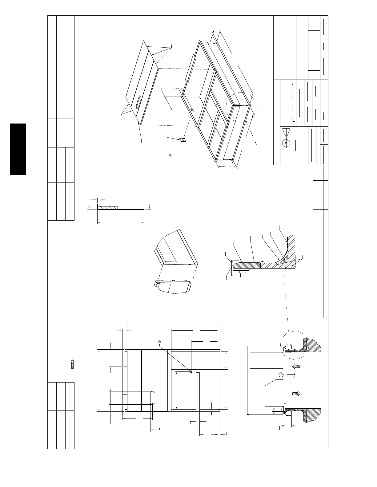
Accessory roof curb details and dimensions are shown in
Fig. 5. Assemble and install accessory roof curb in
accordance with instructions shipped with the curb.
NOTE: The gasketing of the unit to the roof curb is
critical for a watertight seal. Install gasket supplied with
the roof curb as shown in Fig. 5. Improperly applied
gasket can also result in air leaks and poor unit
performance.
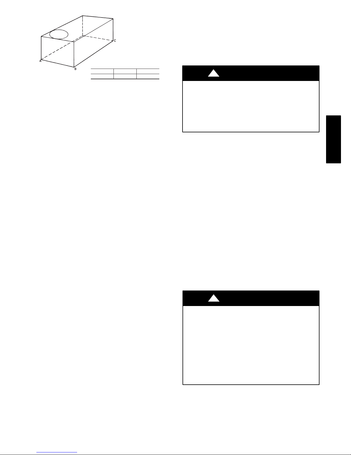
Curb should be level. This is necessary for unit drain to
function properly. Unit leveling tolerances are show in
Fig. 6. Refer to Accessory Roof Curb Installation
Instructions for additional information as required.
581J*
Base Unit 765 (347) 925 (419.5) 925 (419.5) 1090 (495)
Economizer
Vertical 75 (34) 75 (34) 75 (34) 75 (34)
Horizontal 122 (55) 122 (55) 122 (55) 122 (55)
Powered Outlet 35 (16) 35 (16) 35 (16) 35 (16)
Perfect Humidity™ System 80 (36) 80 (36) 80 (36) 85 (39)
Curb
14-in/356 mm 143 (65) 143 (65) 143 (65) 143 (65)
24-in/610 mm 245 (111) 245 (111) 245 (111) 245 (111)
Table 1 – Operating Weights
UNITS LB (KG)
07 08 09 11/12
9
1-3/4"
TYP
[44.5]
C
581J
ACCESSORY CONVENIENCE
OUTLET WIRING CONNECTOR
FITTING
1/2" [12.7] NPT 1/2" [12.7] NPT
CONTROL WIRING
FITTING
POWER WIRING
3/4" [19] NPT 1 1/4" [31.7] NPT
THRU THE CURB
CRBTMPWR004A01 THRU THE BOTTOM
CRBTMPWR002A01
CONNECTOR PKG. ACC. GAS CONNECTION TYPE GAS FITTING
1 3/4"
[44.5]
1.00"
[25.4]
12-1/2" [317.5] WIDE
INSULATED DECK PANELS
INSULATED DECK PANEL
9-15/16" [252.4] WIDE
"A"
1 3/4"
[44.4]
SEE NOTE #2
2-3/8"
[61]
20-3/4"
[513]
INSIDE
GAS SERVICE PLATE
THRU THE CURB
DRILL HOLE
2" [50.8] @
ASSEMBLY (IF
REQUIRED)
(SEE NOTE #8)
SECTION THRU SIDE
RETURN AIR
SUPPLY AIR
UNIT
[1987.5]
6' 6-1/4"
4' 2"
[1270.0]
"A"
NAIL (FIELD SUPPLIED)
TYPICAL (4) SIDES
7/16"
CERTIFIED DRAWING
SEE VIEW "B"
ROOFING FELT
(FIELD SUPPLIED)
COUNTER FLASHING
(FIELD SUPPLIED)
[11]
THIS DOCUMENT AND THE INFORMATION CONTAINED THEREIN
IS PROPRIETARY TO CARRIER CORPORATION AND SHALL NOT
BE USED OR DISCLOSED TO OTHERS, IN WHOLE OR IN PART,
WITHOUT THE WRITTEN AUTHORIZATION OF CARRIER CORPORATION.
1029120
TOLERANCES ON:
AUTHORIZATION NUMBER TITLE
DIMENSIONS ARE IN INCHES
----
UNLESS OTHERWISE SPECIFIED
1 DEC 2 DEC 3 DEC ANG
PRODUCTION
---
MATERIAL
DRAWING RELEASE LEVEL:
THIRD ANGLE
PROJECTION
ROOFING MATERIAL
(FIELD SUPPLIED)
CANT STRIP
(FIELD SUPPLIED)
SHEET 5 OF 5
50HJ405012
CURB ASY, ROOF
SIZE DRAWING NUMBER REV
D
-
-
-
DRAFTER CHECKER
ENGINEERING MANUFACTURING
MMC 12/16/09 - -
-
-
T-005, Y-002
WEIGHT:
- PURCH - N/A -
ENGINEERING REQUIREMENTS
SURFACE FINISH MFG/PURCH MODEL (INTERNAL USE ONLY) NEXT DRAWING SCALE DISTRIBUTION
ECN NO.APP'DCHK'DBYDATEREVISION RECORDREV
1067898--MMC4/22/13
RIGID INSULATION
(FIELD SUPPLIED)
2 1/4"
[57.2]
14 3/4"
[374.7]
NOTES:
1. ROOFCURB ACCESSORY IS SHIPPED DISASSEMBLED.
2. INSULATED PANELS: 25.4 [1"] THK. POLYURETHANE FOAM, 44.5 [1-3/4] # DENSITY.
3. DIMENSIONS IN [ ] ARE IN MILLIMETERS.
4. ROOFCURB: 18 GAGE STEEL.
5. ATTACH DUCTWORK TO CURB. (FLANGES OF DUCT REST ON CURB).
6. SERVICE CLEARANCE 4 FEET ON EACH SIDE.
7. DIRECTION OF AIR FLOW.
8. CONNECTOR PACKAGE CRBTMPWR002A01 IS FOR THRU-THE-CURB GAS TYPE
PACKAGE CRBTMPWR004A01 IS FOR THRU-THE-BOTTOM TYPE GAS CONNECTIONS.
53 1/2"
[1358.9]
11.42"
[290.0]
A
14"
24"
[356]
[610]
26"
[660.4]
6 3/64"
ROOF CURB
ACCESSORY #
CRRFCURB003A01
CRRFCURB004A01
[153.5]
1 3/4"
[44.4]
4 3/16"
[106.0]
81 3/4"
[827.1]
32 9/16"
[2076.3]
3"
40 3/16"
[76.2]
[1020.8]
VIEW "B"
CORNER DETAIL
[585.8]
23 1/16"
OPENING
RETURN AIR
OPENING
SUPPLY AIR
1 3/4"
[44.5]
[401.6]
15 13/16"
DUCT
GASKET
(FIELD SUPPLIED)
(SUPPLIED WITH CURB)
15 15/32
[392.9]
[800.9]
31 17/32"
1 3/4"
[44.5]
6' 61/4" WAS 6' 7 1/6", 4'2' WAS 4' 2 13/16";
18 GA WAS 16 GA.; 15 13/16" WAS 15 15/16"; NAIL
FIELD SUPPLIED WAS WITH CURB
C
SUPPLY AIR RETURN AIR
1/4"
[7.0]
[115.5]
4 9/16"
C13311
Fig. 5 − Roof Curb Details — Sizes 07−12
10
Ducts passing through unconditioned spaces must be
insulated and covered with a vapor barrier.
If a plenum return is used on a vertical unit, the return
should be ducted through the roof deck to comply with
applicable fire codes.
MAXIMUM ALLOWABLE
DIFFERENCE IN. (MM)
A-B
0.5” (13)
Fig. 6 − Unit Leveling Tolerances
Install insulation, cant strips, roofing felt, and counter
flashing as shown. Ductwork must be attached to curb and
not to the unit. The accessory thru−the−base power and
gas connection package must be installed before the unit
is set on the roof curb. If field−installed thru−the−roof
curb gas connections are desired, use factory−supplied
pipe coupling and gas plate assembly to mount the
thru−the−roof curb connection to the roof curb. Gas
connections and power connections to the unit must be
field−installed after the unit is installed on the roof curb.
If electric and control wiring is to be routed through the
basepan, attach the accessory thru−the−base service
connections to the basepan in accordance with the
accessory installation instructions.
Slab Mount (Horizontal Units Only) —
Provide a level concrete slab that extends a minimum of 6
in. (150 mm) beyond unit cabinet. Install a gravel apron in
front of condenser coil air inlet to prevent grass and
foliage from obstructing airflow.
NOTE: Horizontal units may be installed on a roof curb
if required.
Alternate Unit Support
(In Lieu of Curb or Slab Mount) —
B-C
1.0” (25)
A-C
1.0” (25)
C06110
A minimum clearance is not required around ductwork.
!
PROPERTY DAMAGE HAZARD
Failure to follow this caution may result in damage
to roofing materials.
Membrane roofs can be cut by sharp sheet metal
edges. Be careful when placing any sheet metal parts
on such roof.
CAUTION
Step 6 — Rig and Place Unit
Keep unit upright and do not drop. Spreader bars are not
required if top crating is left on unit. Rollers may be used
to move unit across a roof. Level by using unit frame as a
reference. See Table 1 and Fig. 7 for additional
information.
Lifting holes are provided in base rails as shown in Fig. 7.
Refer to rigging instructions on unit.
Rigging materials under unit (cardboard to prevent base
pan damage) must be removed PRIOR to placing the unit
on the roof curb.
When using the standard side drain connection, ensure the
red plug in the alternate bottom connection is tight. Do
this before setting the unit in place. The red drain pan can
be tightened with a 1/2−in. square socket drive extension.
For further details see Step 11 − Install External
Condensate Trap and Line on page 17.
581J
A non−combustible sleeper rail can be used in the unit
curb support area. If sleeper rails cannot be used, support
the long sides of the unit with a minimum of 3 equally
spaced 4−in. x 4−in. (102 mm x 102 mm) pads on each
side.
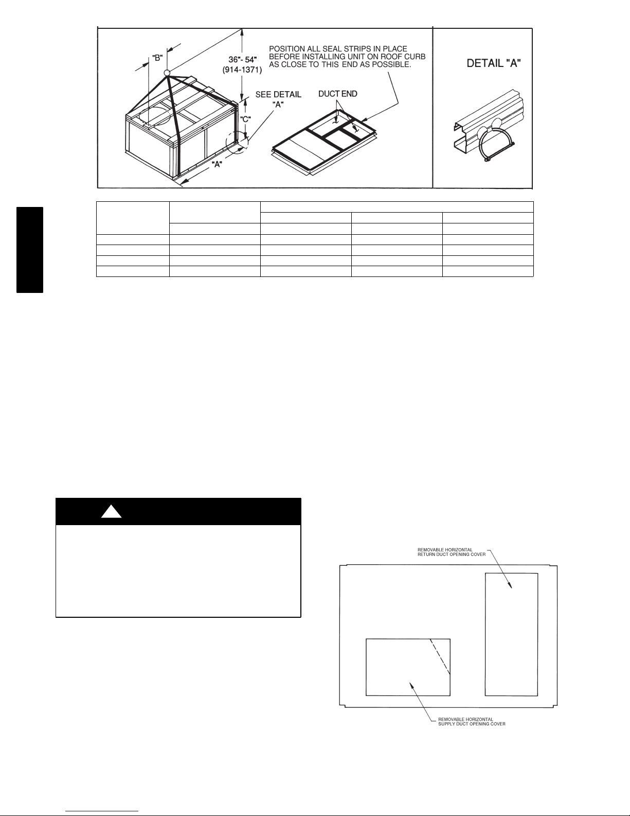
Step 5 — Field Fabricate Ductwork
Cabinet return-air static pressure (a negative condition)
shall not exceed 0.35 in. wg (87 Pa) with economizer or
0.45 in. wg (112 Pa) without economizer.
For vertical ducted applica tions, se cure al l ducts to roof curb
and building structure. Do not connect ductwork to unit.
Fabricate supply ductwork so that the cross sectional
dimensions are equal to or greater than the unit supply
duct opening dimensions for the first 18 in. (458 mm) of
duct length from the unit basepan.
Insulate and weatherproof all external ductwork, joints,
and roof openings with counter flashing and mastic in
accordance with applicable codes.
Before setting the unit onto the curb, recheck gasketing on
curb.
!
UNIT DAMAGE HAZARD
Failure to follow this caution may result in
equipment damage.
All panels must be in place when rigging. Unit is not
designed for handling by fork truck when panels or
packaging are removed.
If using top crate as spreader bar, once unit is set,
carefully lower wooden crate off building roof top to
ground. Ensure that no people or obstructions are
below prior to lowering the crate.
11
CAUTION
581J
UNIT
581J*07 1200 545 88.0 2235 44.0 1120 41.5 1055
581J*08 1420 645 88.0 2235 44.0 1120 49.5 1255
581J*09 1420 645 88.0 2235 44.0 1120 49.5 1255
581J*11/12 1665 757 88.0 2235 32.0 815 49.5 1255
NOTES:
1. SPREADER BARS REQUIRED — Top damage will occur if spreader bars are not used.
2. Dimensions in ( ) are in millimeters.
3. Hook rigging shackles through holes in base rail, as shown in detail “A.” Holes in base rails are centered around the unit center of gravity.
Use wooden top to prevent rigging straps from damaging unit.
MAX WEIGHT
LB KG IN MM IN MM IN MM
A B C
DIMENSIONS
Fig. 7 − Rigging Details
C06005
Positioning on Curb —
Position unit on roof curb so that the following clearances
are maintained: 1/4 in. (6.4 mm) clearance between the
roof curb and the base rail inside the front and back, 0.0
in. clearance between the roof curb and the base rail
inside on the duct end of the unit. This will result in the
distance between the roof curb and the base rail inside on
the condenser end of the unit being approximately 3−5/16
in (84 mm).
Although unit is weatherproof, guard against water from
higher level runoff and overhangs.
!
CAUTION
UNIT DAMAGE HAZARD
Failure to follow this caution may result in
equipment damage.
All panels must be in place when rigging. Unit is not
designed for handling by fork truck when panels or
packaging are removed.
Flue vent discharge must have a minimum horizontal
clearance of 4 ft (1220 mm) from electric and gas meters,
gas regulators, and gas relief equipment. Minimum
distance between unit and other electrically live parts is
48 inches (1220 mm).
NOTE: Installation of accessory flue discharge deflector
kit will reduce the minimum clearance to combustible
material to 18 in. (460 mm).
After unit is in position, remove rigging skids and
shipping materials.
Step 7 — Convert to Horizontal and Connect
Ductwork (when required)
Unit is shipped in the vertical duct configuration. Unit
without factory−installed economizer or return air smoke
detector option may be fi eld−converted to horizontal ducted
configuration. To convert to horizontal configuration,
remove screws from side duct opening covers and remove
covers. Using the same screws, install covers on vertical
duct openings with the insulation−side down. Seals around
duct openings must be ti ght. Se e Fig. 8.
Flue gas can deteriora te building materials. Orient unit such
that flue gas will not affect building materials. Locate
mechanica l draft system flue assembly at lea st 48 in. (1220
mm) from an adjacent building or combustible material.
Fig. 8 − Horizontal Conversion Panels
C06108
12
Field−supplied flanges should be attached to horizontal
S
duct openings and all ductwork should be secured to the
flanges. Insulate and weatherproof all external ductwork,
joints, and roof or building openings with counter flashing
and mastic in accordance with applicable codes.
Do not cover or obscure visibility to the unit’s informative
data plate when insulating horizontal ductwork.
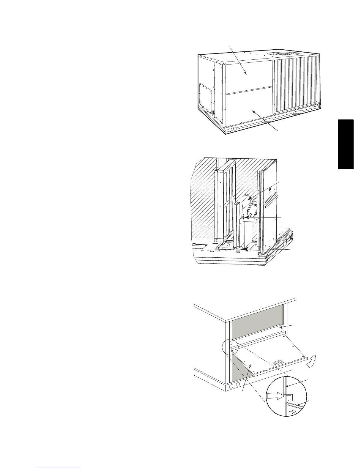
Step 8 — Install Outside Air Hood
Economizer and Two Position Damper Hood
Package Removal and Setup − Factory Option
1. The hood is shipped in knock−down form and must be
field assembled. The indoor coil access panel is used as
the hood top while the hood sides, divider and filter are
packaged together, at tached to a met al support tray using plastic stretch wrap, and shipped in the return air
compartment behind the indoor coil access panel. The
hood assembly’s metal tray is attached to the basepan
and also attached to the damper using two plastic tie−
wraps.
2. To gain access to the hood, remove the filter access
panel. (See Fig. 9.)
3. Locate the (2) screws holding the metal tray to the
basepan and remove. Locate and cut the (2) plastic
tie−wraps securing the assembly to the damper. (See
Fig. 10) Be careful to not damage any wiring or cut
tie−wraps securing any wiring.
4. Carefully lift the hood assembly (with metal tray)
through the filter access opening and assemble per the
steps outlined in Economizer Hood and Two–Position
Hood, below.
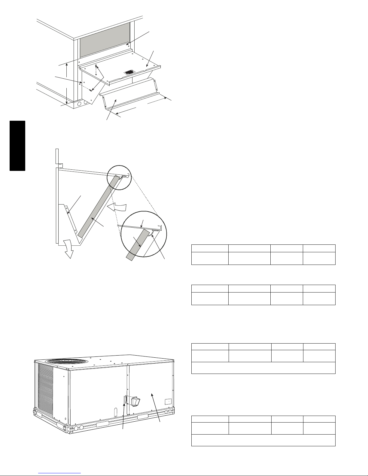
Economizer Hood and Two−Position Hood —
NOTE: If the power exhaust accessory is to be installed
on the unit, the hood shipped with the unit will not be
used and must be discarded. Save the aluminum filter for
use in the power exhaust hood assembly.
1. The indoor coil access panel will be used as the top of
the hood. Remove the screws along the sides and bottom of the indoor coil access panel. See Fig. 11.
2. Swing out indoor coil access panel and insert the hood
sides under the panel (hood top). Use the screws
provided to at tach the hood sides to the hood top. Use
screws provided to attac h the hood sides to the unit . See
Fig. 12.
3. Remove the shipping tape holding the economizer
barometric relief damper in place (economizer only).
4. Insert the hood divider between the hood sides. See
Fig. 12 and 13. Secure hood divider with 2 screws on
each hood side. The hood divider is also used as the
bottom filter rack for the aluminum filter.
5. Open the filter clips which are located underneath the
hood top. Insert the aluminum filter into the bottom
filter rack (hood divider). Push the filter into position
past the open filter clips. Close the filter clips to lock
the filter into place. See Fig. 13.
6. Caulk the ends of the joint between the unit top panel
and the hood top.
7. Replace the filter access panel.
FILTER ACCESS PANEL
INDOOR COIL ACCESS PANEL
C10146
Fig. 9 − Typical Access Panel Locations
Hood Parts
Plastic Tie Wrap
Qty (2)
Screws for Metal Tray
Qty (2)
C08639
Fig. 10 − Economiz er and Two−Position Damper
Hood Parts Locati on
TOP
PANEL
TOP
PANEL
INDOOR
COIL
ACCES
PANEL
C06025
INDOOR
COIL
ACCESS
PANEL
CAULK
HERE
Fig. 11 − Indoor Coil Access Panel Relocation
581J
13
INDOOR COIL
B
R
R
ACCESS PANEL
LEFT
HOOD
SIDE
19 1/16”
B
(483mm)
HOOD DIVIDER
SCREW
33 3/8”
(848mm)
Fig. 12 − Economizer Hood Construction
581J
DIVIDER
OUTSIDE
AIR
HOOD
CLEANABLE
AROMETRIC
ELIEF
ALUMINUM
FILTER
FILTER
Fig. 13 − Economizer Filter Installation
Step 9 — Install Flue Hood
Flue hood is shipped screwed to the basepan beside the
burner compartment access panel. Remove from shipping
location and using screws provided, install flue hood and
screen in location shown in Fig. 14. Insert the flue hood’s
side flange through the access panel cutout, then rotate the
flue hood until the top and bottom flanges contact the
outside of the access panel; secure flue hood with screws.
TOP
PANEL
C06026
FILTE
CLIP
C08634
Step 10 — Install Gas Piping
Installation of the gas piping must be accordance with
local building codes and with applicable national codes.
In U.S.A., refer to NFPA 54/ANSI Z223.1 National Fuel
Gas Code (NFGC). In Canada, installation must be
accordance with the CAN/CSA B149.1 and CAN/CSA
B149.2 installation codes for gas burning appliances.
This unit is factory equipped for use with Natural Gas fuel
at elevations up to 2000 ft (610 m) above sea level. Unit
may be field converted for operation at elevations above
2000 ft (610 m) and/or for use with liquefied petroleum
fuel. See accessory kit installation instructions regarding
these accessories.
NOTE: Furance gas input rate on rating plate is for
installation up to 2000 ft (610 m) above sea level. The
input rating for altitudes above 2000 ft (610 m) must be
derated by 4% for each 1000 ft (305 m) above sea level.
For natural gas applications, gas pressure at unit gas
connection must not be less than 4 in. wg (996 Pa) or
greater than 13 in. wg (3240 Pa) while the unit is
operating. For liquified petroleum applications, the gas
pressure must not be less than 11 in. wg (2740 Pa) or
greater than 13 in. wg (3240 Pa) at the unit connection.
The gas supply pipe enters the unit at the burner access
panel on the front side of the unit, through the long slot at
the bottom of the access panel. The gas connection to the
unit is made to the 1/2−in. or 3/4−in. FPT gas inlet port on
the unit gas valve.
Table 2 – Natural Gas Supply Line Pressure Ranges
UNIT MODEL UNIT SIZE MIN MAX
581J* 07, 08, 09, 11, 12
4.0 in. wg
(996 Pa)
Table 3 – Liquid Propane Supply Line Pressure Ranges
UNIT MODEL UNIT SIZE MIN MAX
581J* 07, 08, 09, 11, 12
11.0 in. wg
(2740 Pa)
Manifold pressure is factory−adjusted for NG fuel use.
Adjust as required to obtain best flame characteristics.
Table 4 – Natural Gas Manifold Pressure Ranges
UNIT MODEL UNIT SIZE HIGH FIRE LOW FIRE
581J* 07, 08, 09, 11, 12
}
NOTE- LOW FIRE, 1.7 in. wg (423 Pa), applies to the following
units only: 581J*07*072/125/150, 581J*08*125 & 581J*09*125
3.5 in. wg
(872 Pa)
13.0 in. wg
(3240 Pa)
13.0 in. wg
(3240 Pa)
}
2.0 in. wg
(498 Pa)
FLUE OPENING
Fig. 14 − Flue Hood Details
Manifold pressure for LP fuel use must be adjusted to
specified range. Follow instructions in the accessory kit to
make initial readjustment.
Table 5 – Liquid Propane Manifold Pressure Ranges
UNIT MODEL UNIT SIZE HIGH FIRE LOW FIRE
BLOWER
ACCESS
PANEL
C12757
581J* 07, 08, 09, 11, 12
}
NOTE- LOW FIRE, 5.0 in. wg (1420 Pa), applies to the following
units only: 581J*07*072/125/150, 581J*08*125 & 581J*09*125
10.0 in. wg
(2490 Pa)
14
}
5.7 in. wg
(1420 Pa)
 Loading...