

Bryant Preferred Series, 581J 04 Series, 581J 06 Series, 581J 05 Series Installation Instructions Manual
Preferred™ Series
581J 04-06 Single Package Rooftop
Gas Heating/Electric Cooling Unit
with Puron® (R-410A) Refrigerant
Installation Instructions
CONTENTS
SAFETY CONSIDERATIONS . . . . . . . . . . . . . . . . . . . . . . 1
Model Number Nomenclature and Dimensions . . . . . . . . . 3
Rated Indoor Airflow . . . . . . . . . . . . . . . . . . . . . . . . . . . . . . 3
INSTALLATION. . . . . . . . . . . . . . . . . . . . . . . . . . . . . . . . . 10
Jobsite Survey . . . . . . . . . . . . . . . . . . . . . . . . . . . . . . . . . . . 10
Step 1 — Plan for Unit Location . . . . . . . . . . . . . . . . . . . . 10
• ROOF MOUNT
Step 2 — Plan for Sequence of Unit Installation . . . . . . . 10
• CURB-MOUNTED INSTALLATION
• PAD-MOUNTED INSTALLATION
• FRAME-MOUNTED INSTALLATION
Step 3 — Inspect Unit . . . . . . . . . . . . . . . . . . . . . . . . . . . . . 10
Step 4 — Provide Unit Support . . . . . . . . . . . . . . . . . . . . . 10
• ROOF CURB MOUNT
• SLAB MOUNT (HORIZONTAL UNITS ONLY)
• ALTERNATE UNIT SUPPORT (IN LIEU OF CURB OR
SLAB MOUNT)
Step 5 — Field Fabricate Ductwork. . . . . . . . . . . . . . . . . . 12
Step 6 — Rig and Place Unit. . . . . . . . . . . . . . . . . . . . . . . . 12
• POSITIONING ON CURB
Step 7 — Convert to Horizontal and Connect Ductwork
(When Required). . . . . . . . . . . . . . . . . . . . . . . . . . . . . . . 13
Step 8 — Install Outside Air Hood . . . . . . . . . . . . . . . . . . 14
• ECONOMIZER AND TWO POSITION DAMPER HOOD
PACKAGE REMOVAL AND SETUP (FACTORY
OPTION)
• ECONOMIZER AND TWO-POSITION HOOD
Step 9 — Units with Hinged Panels Only . . . . . . . . . . . . . 15
Step 10 — Install Flue Hood. . . . . . . . . . . . . . . . . . . . . . . . 15
Step 11 — Install Gas Piping . . . . . . . . . . . . . . . . . . . . . . . 16
• FACTORY-OPTION THRU-BASE CONNECTIONS
(GAS CONNECTIONS)
Step 12 — Install External Condensate Trap and
Line. . . . . . . . . . . . . . . . . . . . . . . . . . . . . . . . . . . . . . . . . . 18
Step 13 — Make Electrical Connections . . . . . . . . . . . . . . 19
• FIELD POWER SUPPLY
• UNITS WITH FACTORY-INSTALLED NON-FUSED
DISCONNECT
• UNITS WITHOUT FACTORY-INSTALLED NONFUSED DISCONNECT
• ALL UNITS
• CONVENIENCE OUTLETS
• FACTORY-OPTION THRU-BASE CONNECTIONS
(ELECTRICAL CONNECTIONS)
• UNITS WITHOUT THRU-BASE CONNECTIONS
(ELECTRICAL CONNECTIONS)
• FIELD CONTROL WIRING
• THERMOSTAT
• HEAT ANTICIPATOR SETTINGS
• PERFECT HUMIDITY™ CONTROL CONNECTIONS
• LOW AMBIENT CONTROL (FACTORY OPTION)
• INTEGRATED GAS CONTROLLER
Economi$er® X (Factory Option) . . . . . . . . . . . . . . . . . . . 27
• SYSTEM COMPONENTS
• SPECIFICATIONS
•INPUTS
•OUTPUTS
• ENVIRONMENTAL
• ECONOMIZER MODULE WIRING DETAILS
• INTERFACE OVERVIEW
• SETUP AND CONFIGURATION
• ENTHALPY SETTINGS
• CHECKOUT
• TROUBLESHOOTING
RTU OPEN CONTROL SYSTEM . . . . . . . . . . . . . . . . . . 37
Smoke Detectors . . . . . . . . . . . . . . . . . . . . . . . . . . . . . . . . . 37
• COMPLETING RETURN-AIR SMOKE SENSOR
INSTALLATION
• ADDITIONAL APPLICATION DATA
Step 14 — Adjust Factory-Installed Options . . . . . . . . . . 39
• SMOKE DETECTORS
• ECONOMI$ER IV OCCUPANCY SWITCH
Step 15 — Install Accessories. . . . . . . . . . . . . . . . . . . . . . . 39
Step 16 — Check Belt Tension. . . . . . . . . . . . . . . . . . . . . . 39
• BELT FORCE — DEFLECTION METHOD
• BELT TENSION METHOD
Pre-Start and Start-Up . . . . . . . . . . . . . . . . . . . . . . . . . . . . 40
START-UP CHECKLIST . . . . . . . . . . . . . . . . . . . . . . .CL-1
SAFETY CONSIDERATIONS
Installation and servicing of air-conditioning equipment can be
hazardous due to system pressure and electrical components.
Only trained and qualified service personnel should install,
repair, or service air-conditioning equipment.
Untrained personnel can perform basic maintenance functions
of cleaning coils and filters and replacing filters. All other
operations should be performed by trained service personnel.
When working on air-conditioning equipment, observe
precautions in the literature, tags and labels attached to the
unit, and other safety precautions that may apply.
Follow all safety codes, including ANSI (American National
Standards Institute) Z223.1. Wear safety glasses and work
gloves. Use quenching cloth for unbrazing operations. Have
fire extinguisher available for all brazing operations.
It is important to recognize safety information. This is the
safety-alert symbol . When you see this symbol on the unit
and in instructions or manuals, be alert to the potential for
personal injury.
Understand the signal words DANGER, WARNING,
CAUTION, and NOTE. These words are used with the safetyalert symbol. DANGER identifies the most serious hazards
which will result in severe personal injury or death.
WARNING signifies hazards which could result in personal
injury or death. CAUTION is used to identify unsafe practices,
which may result in minor personal injury or product and
property damage. NOTE is used to highlight suggestions
which will result in enhanced installation, reliability, or
operation.
Catalog No. 04-53581010-01 Printed in U.S.A. Form II581J-4-6-02 Pg 1 4-19 Replaces: II581J-4-6-01
Manufacturer reserves the right to discontinue, or change at any time, specifications or designs without notice and without incurring obligations.
WARNING
GAS VALVE
INLET PRESSURE
TAP SET SCREW
Electrical shock can cause personal injury and death. Shut
off all power to this equipment during installation. There
may be more than one disconnect switch. Tag all disconnect
locations to alert others not to restore power until work is
completed.
WARNING
WARNING
CARBON-MONOXIDE POISONING HAZARD
Failure to follow instructions could result in severe personal
injury or death due to carbon-monoxide poisoning, if combustion products infiltrate into the building.
Check that all openings in the outside wall around the vent
(and air intake) pipe(s) are sealed to prevent infiltration of
combustion products into the building.
Check that furnace vent (and air intake) terminal(s) are not
obstructed in any way during all seasons.
FIRE, EXPLOSION HAZARD
Failure to follow this warning could result in death, serious
personal injury and/or property damage.
Disconnect gas piping from unit when pressure testing at
pressure greater than 0.5 psig (3450 Pa). Pressures greater
than 0.5 psig will cause gas valve damage resulting in hazardous condition. If gas valve is subjected to pressure greater than 0.5 psig, it must be replaced before use. When pressure testing field-supplied gas piping at pressures of
0.5 psig or less, a unit connected to such piping must be
isolated by closing the manual gas valve(s).
WARNING
UNIT OPERATION AND SAFETY HAZARD
Failure to follow this warning could cause personal injury,
death and/or equipment damage.
®
Puron
(R-410A) refrigerant systems operate at higher pressures than standard R-22 systems. Do not use R-22 service
equipment or components on Puron refrigerant equipment.
WARNING
PERSONAL INJURY AND ENVIRONMENTAL
HAZARD
Failure to follow this warning could cause personal injury
or death.
Relieve pressure and recover all refrigerant before system
repair or final unit disposal.
Wear safety glasses and gloves when handling refrigerants.
Keep torches and other ignition sources away from refrigerants and oils.
AVERTISSEMENT
RISQUE D’INTOXICATION AU MONOXYDE DE
CARBONE
Si ces directives ne sont pas suivies, cela peut entraîner des
blessures graves ou une intoxication au monoxyde de
carbone pouvant causer la mort, si des produits de
combustion s’infiltrent dans le bâtiment.
Vérifier que toutes les ouvertures pratiquées dans le mur
extérieur autour du ou des tuyaux d’évent (et de la prise
d’air) sont scellées de manière à empêcher l’infiltration de
produits de combustion dans le bâtiment.
Veiller à ce que la ou les sorties de l’évent de l’appareil de
chauffage (et la prise d’air) ne soient, en aucune façon,
obstruées, quelle que soit la saison.
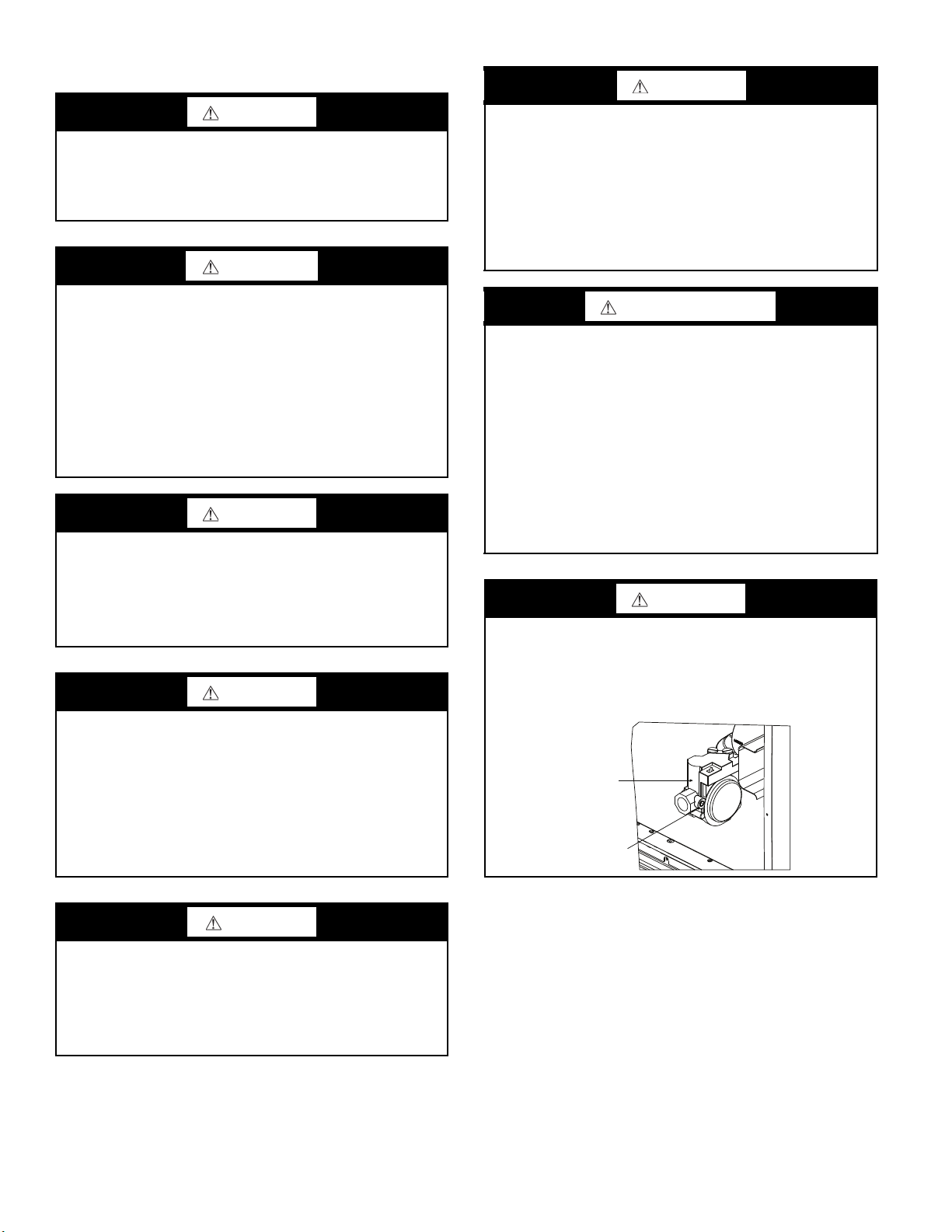
WARNING
FIRE HAZARD
Failure to follow this warning could result in personal inju-
ry, death, and/or property damage.
Inlet pressure tap set screw must be tightened and
NPT pipe plug must be installed to prevent gas leaks.
1
/8-in.
CUT HAZARD
Failure to follow this caution may result in personal injury.
Sheet metal parts may have sharp edges or burrs. Use care
and wear appropriate protective clothing, safety glasses and
gloves when handling parts and servicing air conditioning
equipment.
CAUTION
2

WARNING
MANIFOLD
GAS VALVE
MANIFOLD PRESSURE
TAP SET SCREW
FIRE HAZARD
Failure to follow this warning could result in personal inju-
ry, death, and/or property damage.
Manifold pressure tap set screw must be tightened and
in. NPT pipe plug must be installed to prevent gas leaks.
1
/8-
MODEL NUMBER NOMENCLATURE AND
DIMENSIONS
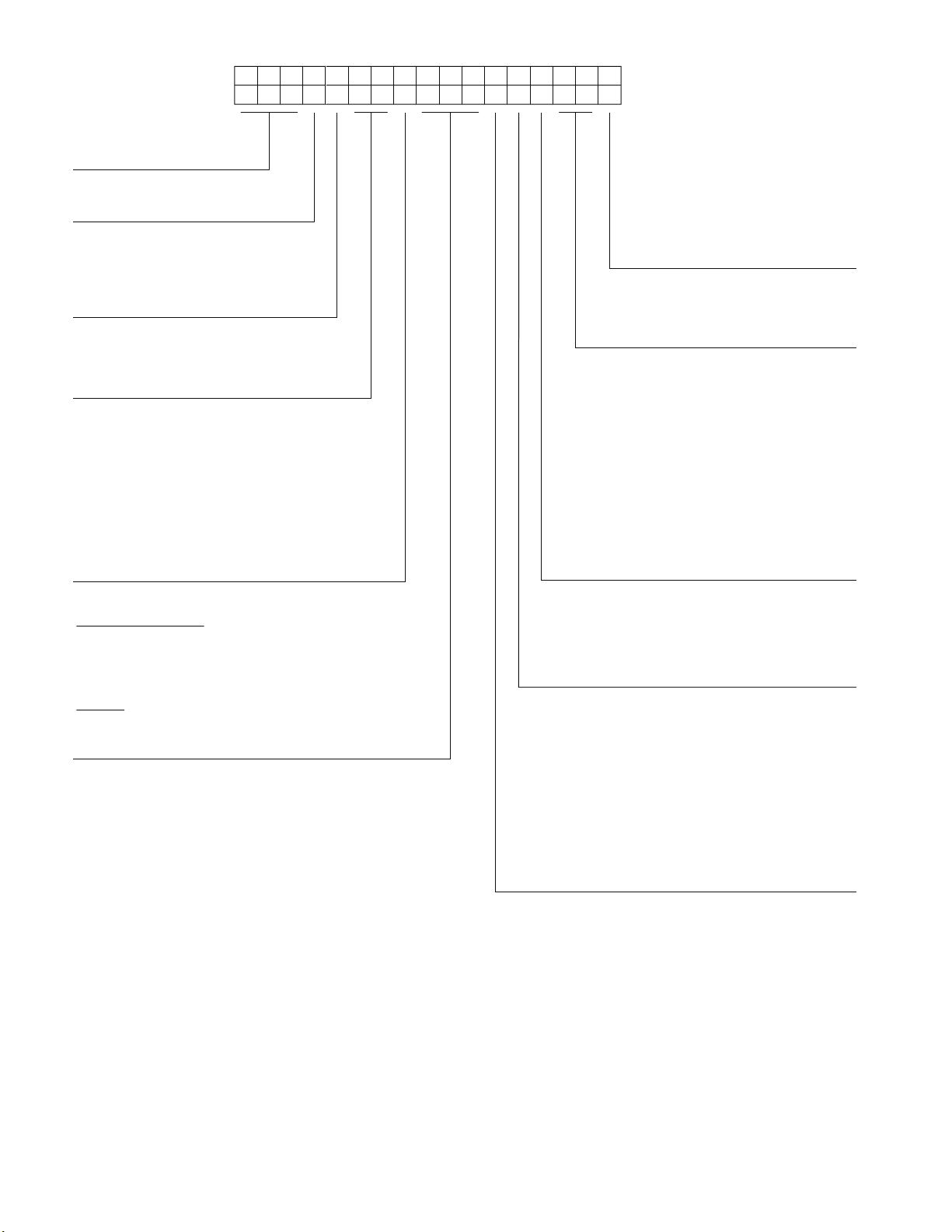
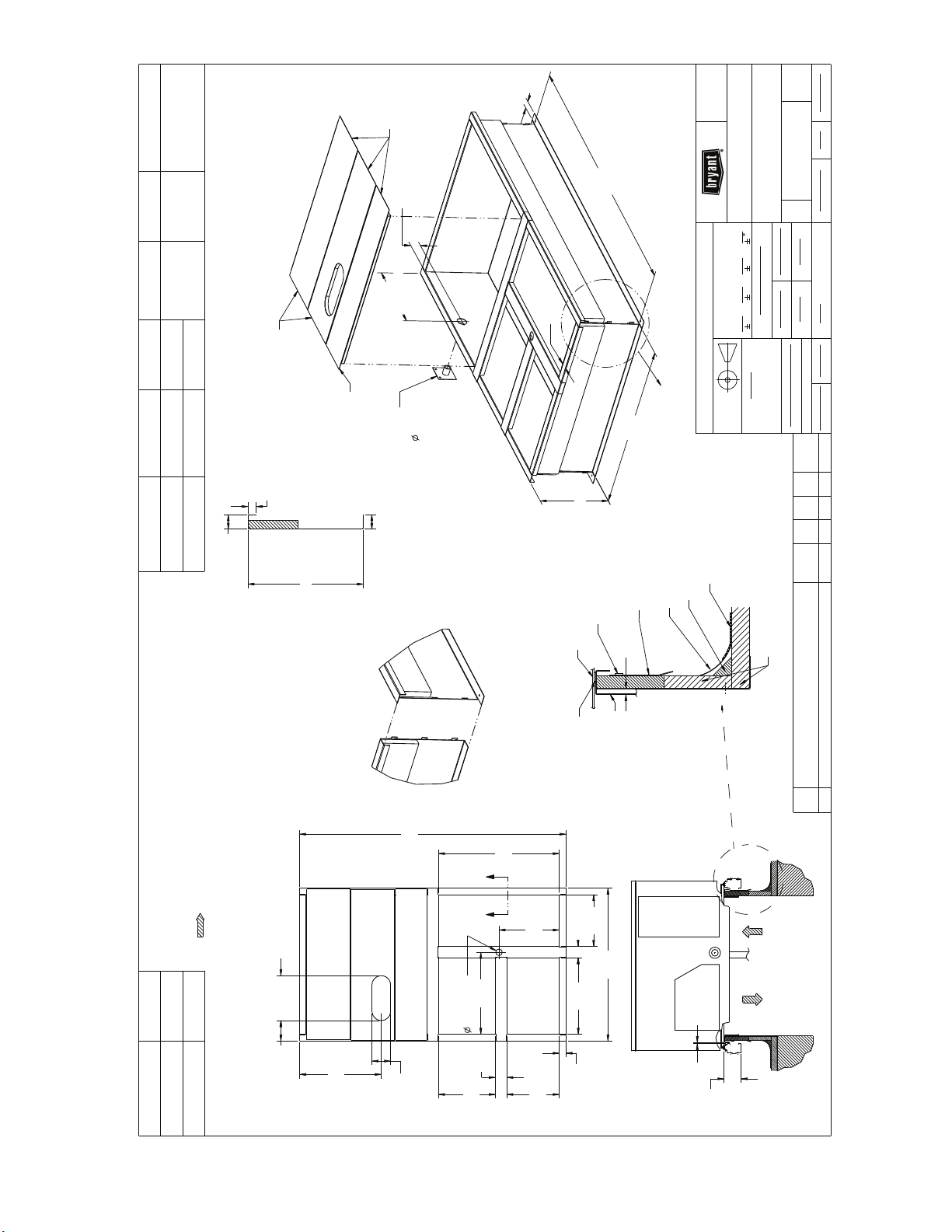
See Fig. 1 for 581J model number nomenclature. See Fig. 2
and 3 for unit dimensional drawings. See Fig. 4 for corner
weights and clearance dimensions. See Fig. 5 for base rail details. See Fig. 6 for thru-the-base charts.
Rated Indoor Airflow
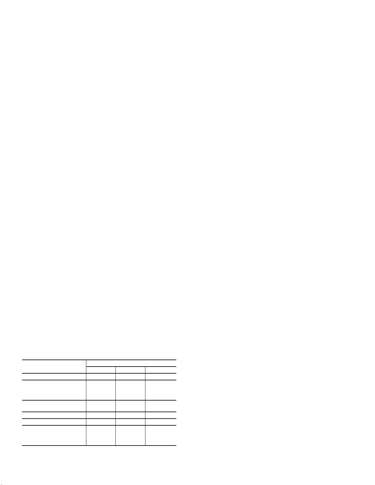
Table 1 lists the rated indoor airflow used for the AHRI efficiency rating for the units covered in this document.
Table 1 — Rated Indoor Airflow
MODEL NUMBER FULL LOAD AIRFLOW (CFM)
581J*04 1050
581J*05 1400
581J*06 1625
3
Model
J - Puron
®
(R-410A) Refrigerant
Unit Type
581 - High Efficiency Gas Heat RTU
Packaging and 2-Speed Fan Motor
A = Standard Packaging, electro-mechanical
controls that require W7212 EconoMi$er IV
B = LTL Packaging, electro-mechanical
controls that require W7212 EconoMi$er IV
C = Standard Packaging, electro-mechanical
controls that require W7220 EconoMi$er X
F =
LTL Packaging,
electro-mechanical controls
that require W7212 EconoMi$er IV
Cooling Tons
04 - 3 tons
05 - 4 tons
06 - 5 tons
Heat Level Input
Standard/Stainless Steel
1 Phase Models 3 Phase Models
065 = 65,000 072 = 72,000
090 = 90,000 115 = 115,000
130 = 130,000 150 = 150,000
Low NOx
060 = 60,000
090 = 90,000
120 = 120,000
Indoor Fan Options
0 = Electric (Direct) Drive X13 Motor (not available with Perfect
Humidity)
1 = Standard Static - Belt Drive
2 = Medium Static - Belt Drive
3 = High Static - Belt Drive
Refrig. System/Gas Heat Options
A = Standard one stage cooling models/Natural Gas heat
B = Standard one stage cooling models/Low NO
x
heat
C = Standard one stage cooling models/
Stainless Steel gas heat exchanger
G = Standard one stage cooling models
and Perfect Humidity™
H = Standard one stage cooling models/Low NO
x
heat
and Perfect Humidity™
J = Standard one stage cooling models/Stainless Steel
gas heat exchanger and Perfect Humidity™
Coil Options (RTPF) (Outdoor - Indoor - Hail Guard)
A = Al/Cu - Al/Cu
B = Precoat Al/Cu - Al/Cu
C = E-coat Al/Cu - Al/Cu
D = E-coat Al/Cu - E-coat Al/Cu
E = Cu/Cu - Al/Cu
F = Cu/Cu - Cu/Cu
M = Al/Cu - Al/Cu — Louvered Hail Guard
N = Precoat Al/Cu - Al/Cu — Louvered Hail Guard
P = E-coat Al/Cu - Al/Cu — Louvered Hail Guard
Q = E-coat Al/Cu - E-coat Al/Cu — Louvered Hail Guard
R = Cu/Cu - Al/Cu — Louvered Hail Guard
S = Cu/Cu - Cu/Cu — Louvered Hail Guard
Voltage
E = 460-3-60
J = 208/230-1-60
P = 208/230-3-60
T = 575-3-60
Outdoor Air Options
A = None
B = Temperature Economizer w/ Barometric Relief,
Standard Leak (W7212 or W7220)
E = Temperature Economizer w/ Barometric Relief,
Standard Leak w/ CO
2
(W7212 or W7220)
H =
Enthalpy
Economizer w/ Barometric Relief,
Standard Leak (W7212 or W7220)
L =
Enthalpy
Economizer w/ Barometric Relief,
Standard Leak w/ CO
2
(W7212 or W7220)
Q =
Motorized 2-Position Damper
U =
Temperature Economizer w/ Barometric Relief,
Ultra Low Leak (W7220)
W =
Enthalpy
Economizer w/ Barometric Relief,
Ultra Low Leak (W7220)
Example:
Position:
581JE0 6A072A1A0AA
1234567891011 12 13 14 15 16 17
Factory Installed Options
0A = None
NOTE: See the 581J Price Pages for a
complete list of factory installed options.
NOTE: On single phase (-J voltage code) models, the
following are not available as factory installed options:
- Perfect Humidity
TM
- Coated Coils or Cu Fin Coils
- Louvered Hail Guards
- EconoMi$er
®
or 2 Position Damper
- Powered 115 Volt Convenience Outlet
Fig. 1 — 581J 04-06 Model Number Nomenclature (Example)
4
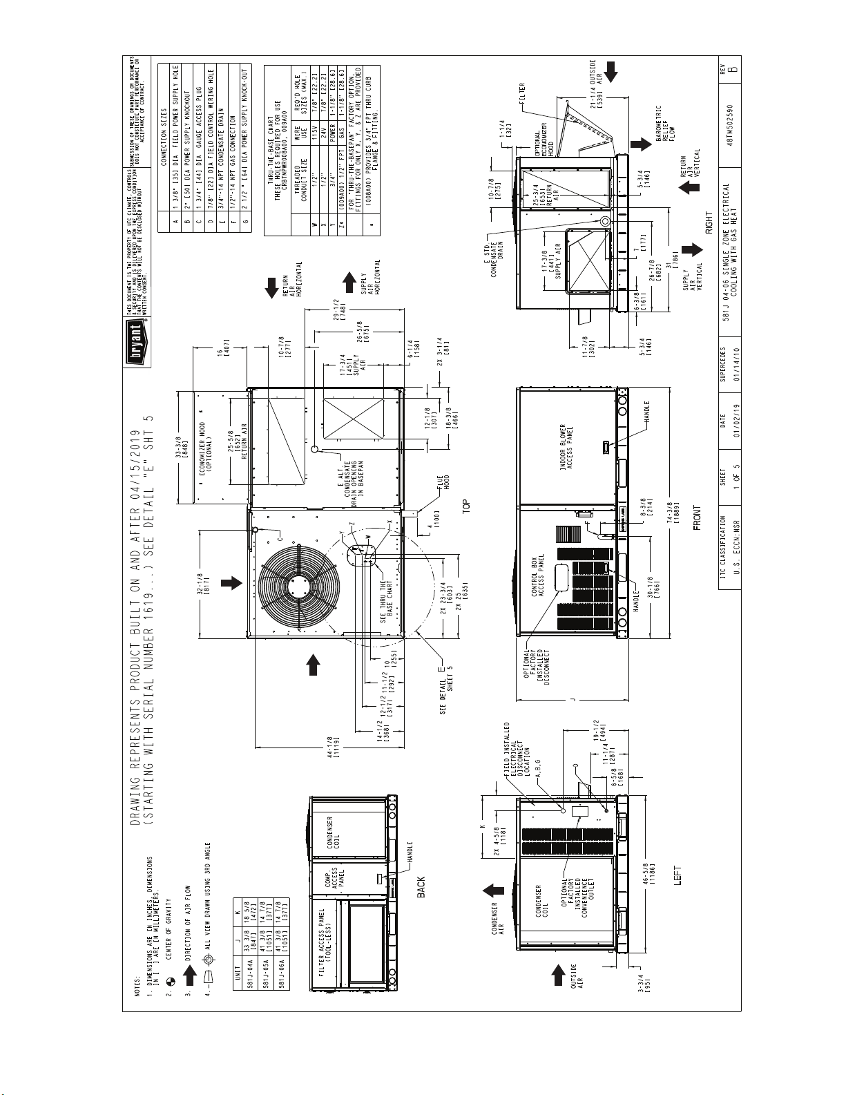
Fig. 2 — Dimensional Drawing for Units Built On or After 4/15/19
5
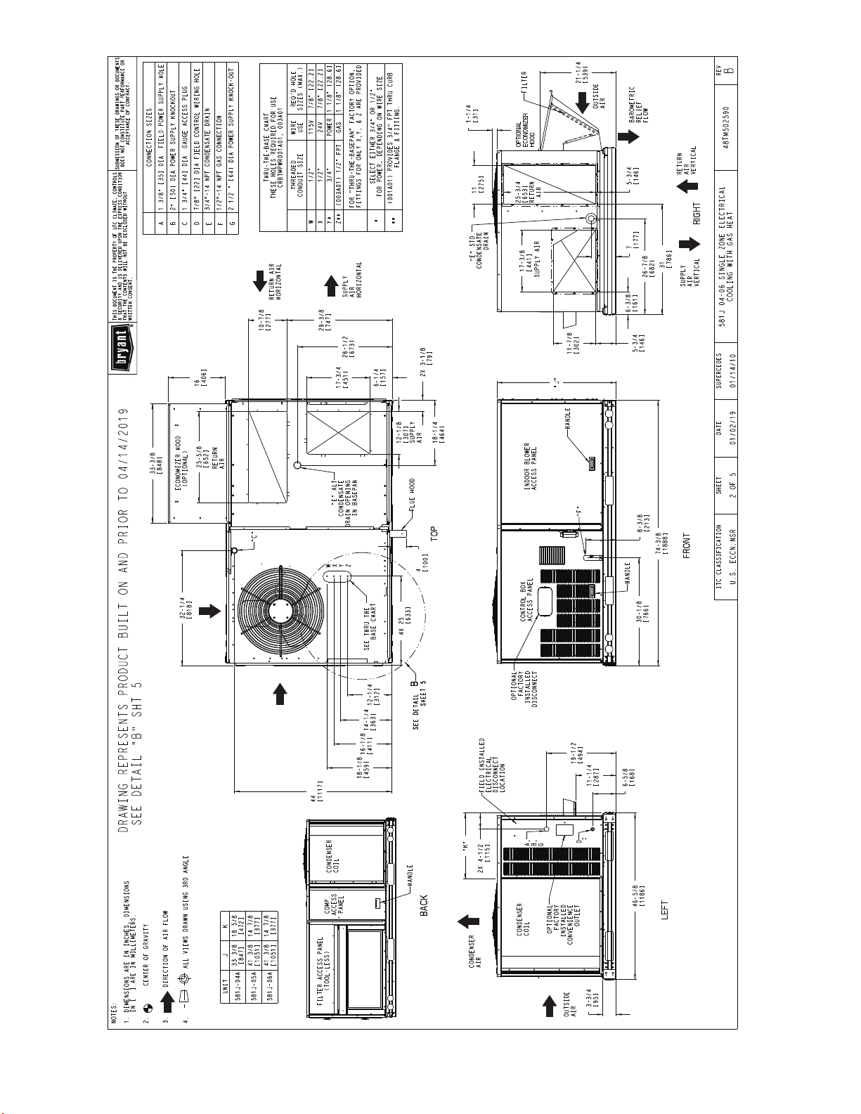
Fig. 3 — Dimensional Drawing for Units Built On or Prior to 4/14/19
6
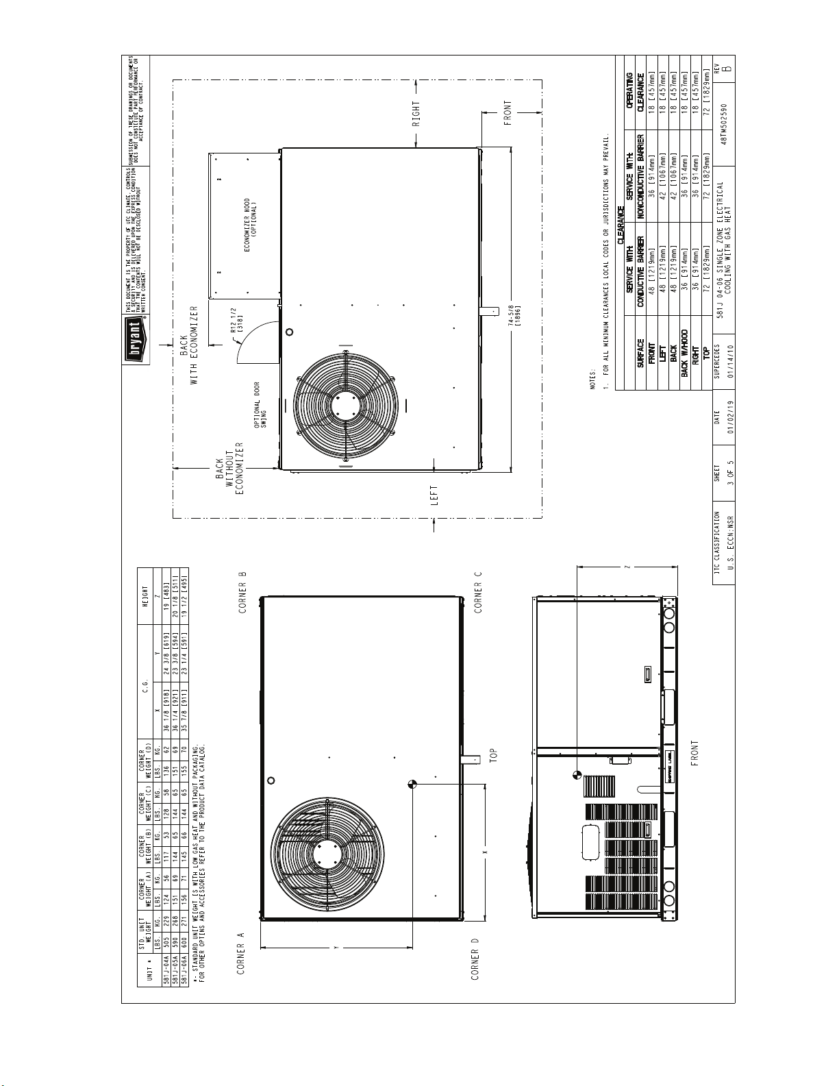
Fig. 4 — Corner Weights and Clearances
7
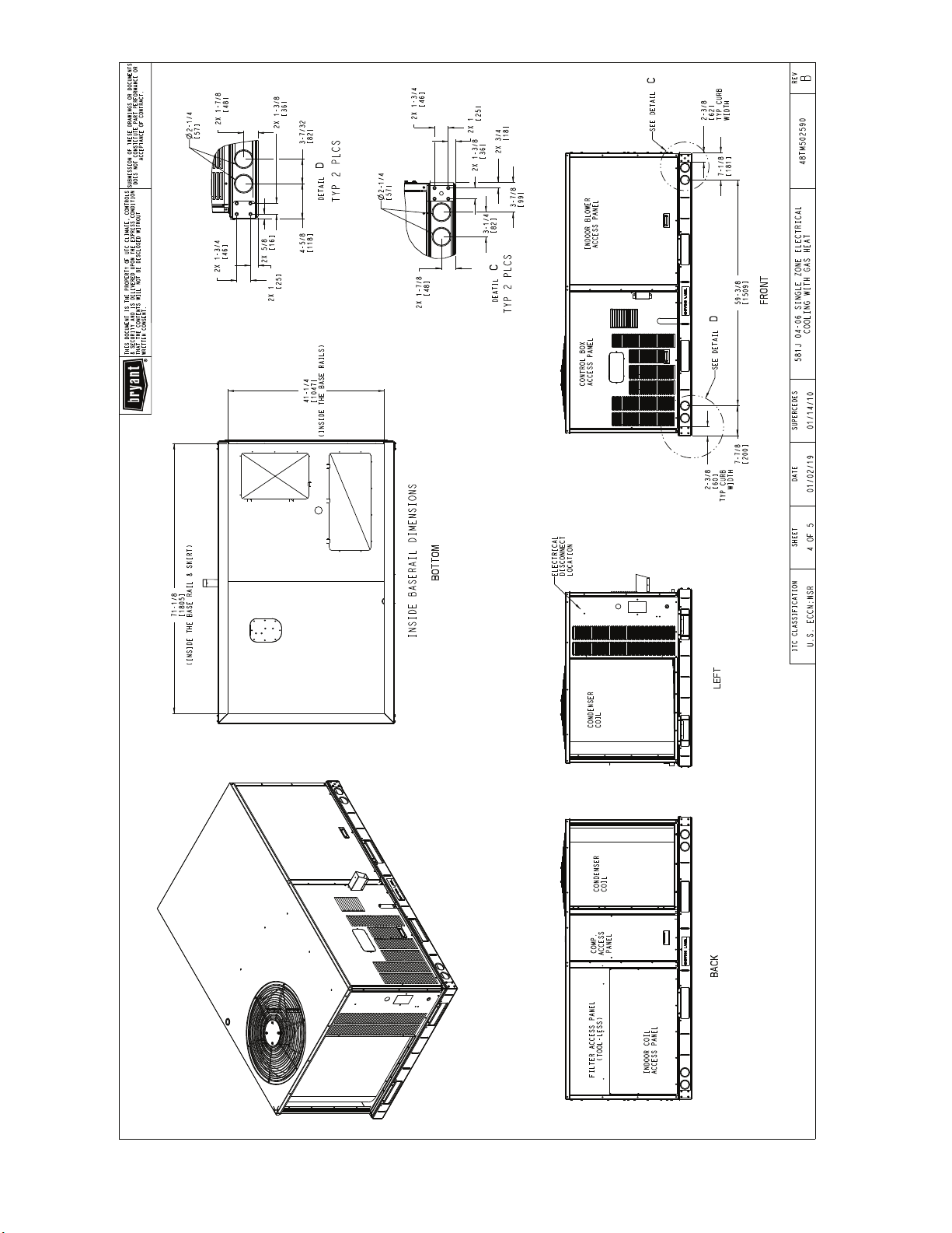
Fig. 5 — Base Rail Details
8
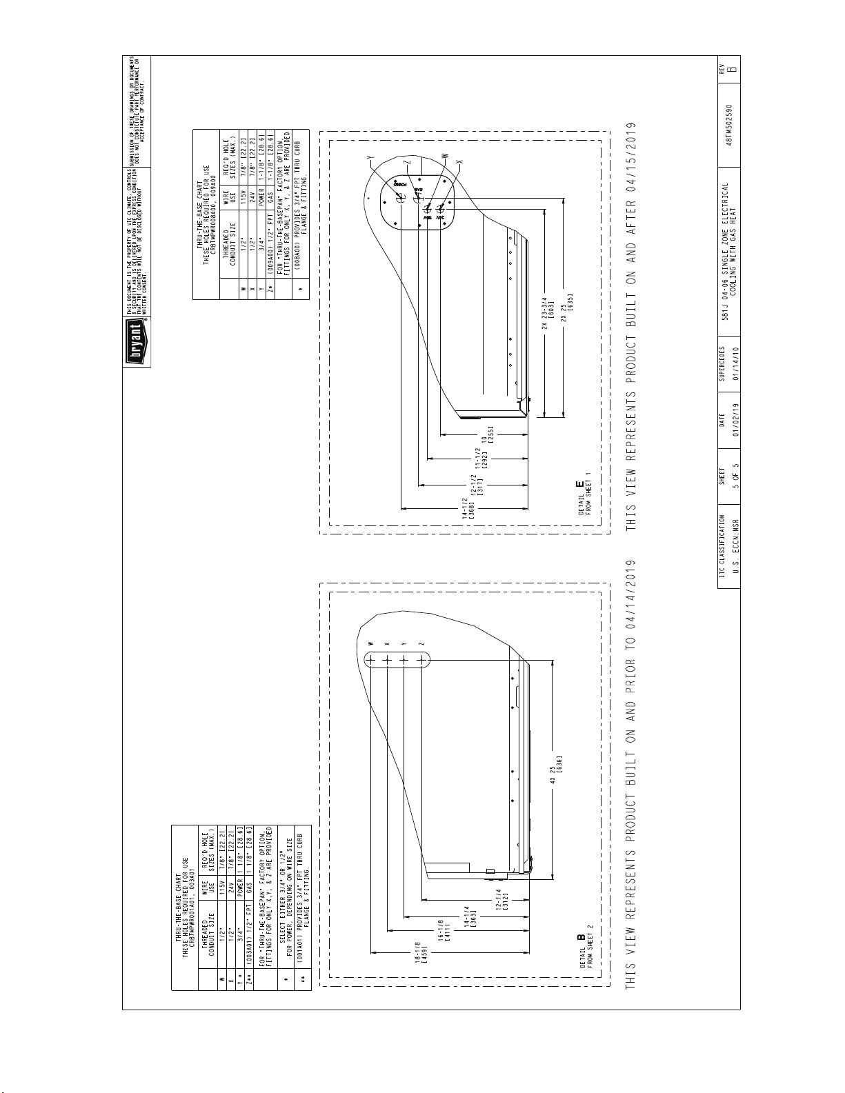
Fig. 6 — Thru-the-Base Charts
9
INSTALLATION
Jobsite Survey
Complete the following checks before installation.
1. Consult local building codes and the NEC (National Electrical Code) ANSI/NFPA 70 for special installation
requirements.
2. Determine unit location (from project plans) or select unit
location.
3. Check for possible overhead obstructions which may
interfere with unit lifting or rigging.
Step 1 — Plan for Unit Location
Select a location for the unit and its support system (curb or
other) that provides for the minimum clearances required for
safety. This includes the clearance to combustible surfaces,
unit performance and service access below, around, and above
unit as specified in unit drawings. See Fig. 4 for clearances.
NOTE: Consider also the effect of adjacent units.
Be sure that unit is installed such that snow will not block the
combustion intake or flue outlet.
Unit may be installed directly on wood flooring or on Class A,
B, or C roof-covering material when roof curb is used.
Do not install unit in an indoor location. Do not locate air inlets
near exhaust vents or other sources of contaminated air. For proper
unit operation, adequate combustion and ventilation air must be
provided in accordance with Section 5.3 (Air for Combustion and
Ventilation) of the National Fuel Gas Code, ANSI Z223.1 (American National Standards Institute) and NFPA (National Fire Protection Association) 54 TIA-54-84-1. In Canada, installation must be
in accordance with the CAN1-B149 installation codes for gas
burning appliances.
Although unit is weatherproof, avoid locations that permit water from higher level runoff and overhangs to fall onto the unit.
Locate mechanical draft system flue assembly at least 4 ft
(1.2 m) from any opening through which combustion products
could enter the building, and at least 4 ft (1.2 m) from any adjacent building (or per local code). Locate the flue assembly at
least 10 ft (3.05 m) from an adjacent unit’s fresh air intake
hood if within 3 ft (0.91 m) of same elevation (or per local
code). When unit is located adjacent to public walkways, flue
assembly must be at least 7 ft (2.1 m) above grade.
Select a unit mounting system that provides adequate height to
allow installation of condensate trap per requirements. Refer to
Step 12 — Install External Condensate Trap and Line on
page 18 for required trap dimensions.
ROOF MOUNT
Check building codes for weight distribution requirements.
Unit operating weights are shown in Table 2.
Table 2 — Unit Operating Weights
581J
Base Unit 505 (229) 590 (268) 600 (272)
Economizer
Vertical 50 (23) 50 (23) 50 (23)
Horizontal 80 (36) 80 (36) 80 (36)
Perfect Humidity™
System
Cu Fins 25 (11) 43 (20) 56 (25)
Powered Outlet 32 (15) 32 (15) 32 (15)
Curb
14-in. (356 mm) 110 (50) 110 (50) 110 (50)
24-in. (610 mm) 145 (66) 145 (66) 145 (66)
27 (10) 34 (13) 34 (13)
UNIT LB (KG)
04 05 06
Step 2 — Plan for Sequence of Unit Installation
The support method used for this unit will dictate different sequences for the steps of unit installation. For example, on curbmounted units, some accessories must be installed on the unit
before the unit is placed on the curb. Review the following for
recommended sequences for installation steps.
CURB-MOUNTED INSTALLATION
1. Install curb
2. Install field-fabricated ductwork inside curb
3. Install accessory thru-base service connection package
(affects curb and unit) (refer to accessory installation
instructions for details)
4. Prepare bottom condensate drain connection to suit
planned condensate line routing (refer to Step 12 on
page 18 for details)
5. Rig and place unit
6. Install outdoor air hood
7. Install flue hood
8. Install gas piping
9. Install condensate line trap and piping
10. Make electrical connections
11. Install other accessories
PAD-MOUNTED INSTALLATION
1. Prepare pad and unit supports
2. Check and tighten the bottom condensate drain connection
plug
3. Rig and place unit
4. Convert unit to side duct connection arrangement
5. Install field-fabricated ductwork at unit duct openings
6. Install outdoor air hood
7. Install flue hood
8. Install gas piping
9. Install condensate line trap and piping
10. Make electrical connections
11. Install other accessories
FRAME-MOUNTED INSTALLATION
Frame-mounted applications generally follow the sequence for
a curb installation. Adapt the sequence as required to suit specific installation plan.
Step 3 — Inspect Unit
Inspect unit for transportation damage. File any claim with
transportation agency.
Confirm before installation of unit that voltage, amperage and
circuit protection requirements listed on unit data plate agree
with power supply provided.
On units with hinged panel option, check to be sure all latches
are snug and in closed position.
Locate the carton containing the outside air hood parts. Do not
remove carton until unit has been rigged and located in final
position.
Step 4 — Provide Unit Support
ROOF CURB MOUNT
Accessory roof curb details and dimensions are shown in
Fig. 7. Assemble and install accessory roof curb in accordance
with instructions shipped with the curb.
The gasketing of the unit to the roof curb is critical for a watertight seal. Install gasket supplied with the roof curb as shown
in Fig. 7. Improperly applied gasket can also result in air leaks
and poor unit performance.
10
ACCESSORY CONVENIENCE
OUTLET WIRING CONNECTOR
FITTING
1/2" [12.7] NPT 1/2" [12.7] NPT
CONTROL WIRING
FITTING
3/4" [19] NPT
POWER WIRING
1/2" [12.7] NPTCRRFCURB002A01
THRU THE CURB
CRBTMPWR003A01 THRU THE BOTTOM
CRBTMPWR001A01 3/4" [19] NPT
CONNECTOR PKG. ACC. GAS CONNECTION TYPE GAS FITTING
1-3/4"
[44.5]
11 3/4"[298.5] WIDE
INSULATED DECK PANELS
1.00"
[25.4]
"A"
SEE NOTE #2
2-3/8"
[61]
1' 4-13/16"
[427] INSIDE
8 9/16"[217.5] WIDE
INSULATED DECK PANEL
GAS SERVICE PLATE
THRU THE CURB
1-3/4"
[44.4]
E-ESECTION
SCALE 0.250
DRILL HOLE
2" [50.8] @
ASSEMBLY (IF
REQUIRED)
(SEE NOTE #8)
1-3/4"
[44.4]
RETURN AIR
1-3/4"
SUPPLY AIR
[44.5]
"A"
UNIT
[1711.3]
5' 7-3/8"
[944.6]
3'-1 3/16"
COUNTER FLASHING
NAIL (FIELD SUPPLIED)
(FIELD SUPPLIED)
TYPICAL (4) SIDES
7/16"
[11]
SYRACUSE, NY.
INDIANAPOLIS, IN.
THIS DOCUMENT AND THE INFORMATION CONTAINED THEREIN
IS PROPRIETARY TO CARRIER CORPORATION AND SHALL NOT
BE USED OR DISCLOSED TO OTHERS, IN WHOLE OR IN PART,
WITHOUT THE WRITTEN AUTHORIZATION OF CARRIER CORPORATION.
TOLERANCES ON:
DIMENSIONS ARE IN INCHES
- - - -
UNLESS OTHERWISE SPECIFIED
1 DEC 2 DEC 3 DEC ANG
PRODUCTION
CERTIFIED DRAWING
MATERIAL
DRAWING RELEASE LEVEL:
THIRD ANGLE
PROJECTION
SEE VIEW "B"
ROOFING MATERIAL
(FIELD SUPPLIED)
CANT STRIP
(FIELD SUPPLIED)
ROOFING FELT
(FIELD SUPPLIED)
B
(004-007)
SHEET 5 OF 5
48TC400427
CURB ASY, ROOF
SIZE DRAWING NUMBER REV
D
-
-
-
1041738
AUTHORIZATION NUMBER TITLE
DRAFTER CHECKER
ENGINEERING MANUFACTURING
MMC 06/17/11 - -
-
---
-
T-005, Y-002
WEIGHT:
ENGINEERING REQUIREMENTS
SURFACE FINISH MFG/PURCH MODEL (INTERNAL USE ONLY) NEXT DRAWING SCALE DISTRIBUTION
1067898--MMC04/22/13
RIGID INSULATION
(FIELD SUPPLIED)
- PURCH - N/A MMC
ECN NO.APP'DCHK'DBYDATEREVISION RECORDREV
NOTES:
1. ROOFCURB ACCESSORY IS SHIPPED DISASSEMBLED.
2. INSULATED PANELS: 25.4 [1"] THK. POLYURETHANE FOAM, 44.5 [1-3/4] # DENSITY.
3. DIMENSIONS IN [ ] ARE IN MILLIMETERS.
4. ROOFCURB: 18 GAGE STEEL.
5. ATTACH DUCTWORK TO CURB. (FLANGES OF DUCT REST ON CURB).
6. SERVICE CLEARANCE 4 FEET ON EACH SIDE.
7. DIRECTION OF AIR FLOW.
8. CONNECTOR PACKAGE CRBTMPWR001A01 IS FOR THRU-THE-CURB GAS TYPE
PACKAGE CRBTMPWR003A01 IS FOR THRU-THE-BOTTOM TYPE GAS CONNECTIONS.
A
14"
ROOF CURB
ACCESSORY #
CRRFCURB001A01
[356]
24"
[610]
11.96"
5.42"
[303.8]
[137.7]
21.74"
[552.2]
Fig. 7 — Roof Curb Details
4.96"
70.87"
[126.0]
[1800.2]
E
E
RETURN AIR
OPENING
21.84"
1/3/4"[44.5]
3.00"
15.19"
[385.8]
32.19"
[554.7]
[76.2]
VIEW "B"
CORNER DETAIL
[817.6]
16.03"
SUPPLY AIR
14.00"
[407.2]
OPENING
[355.6]
DUCT
GASKET
(FIELD SUPPLIED)
(SUPPLIED WITH CURB)
13.78"
[350.0]
3.00"
[76.2]
40.69"
[1033.5]
20.41"
[518.3]
1.75"
[44.5]
OVERALL DIM. 5'-7 3/8" WAS 5'-7 7/8; 18GA
MATERIAL WA 16 GA.; NAIL FIELD SUPPLIED WAS
WITH CURB
A
SUPPLY AIR RETURN AIR
1/4"
[7.0]
[115.5]
4 9/16"
11
Curb should be level. This is necessary for unit drain to func-
A
MAXIMUM ALLOWABLE
DIFFERENCE IN. (MM)
A-B B-C A-C
0.5 (13) 1.0 (25) 1.0 (25)
tion properly. Unit leveling tolerances are shown in Fig. 8. Refer to Accessory Roof Curb Installation Instructions for additional information as required.
Install insulation, cant strips, roofing felt, and counter flashing
as shown. Ductwork must be attached to curb and not to the
unit. The accessory thru-the-base power and gas connection
package must be installed before the unit is set on the roof
curb. If field-installed thru-the-roof curb gas connections are
desired, use factory-supplied
1
/2-in. pipe coupling and gas plate
assembly to mount the thru-the-roof curb connection to the
roof curb. Gas connections and power connections to the unit
must be field-installed after the unit is installed on the roof
curb.
If electric and control wiring is to be routed through the basepan,
attach the accessory thru-the-base service connections to the basepan in accordance with the accessory installation instructions.
C
B
Fig. 8 — Unit Leveling Tolerances
SLAB MOUNT (HORIZONTAL UNITS ONLY)
Provide a level concrete slab that extends a minimum of 6-in.
(150 mm) beyond unit cabinet. Install a gravel apron in front of
condenser coil air inlet to prevent grass and foliage from obstructing airflow.
NOTE: Horizontal units may be installed on a roof curb if
required.
ALTERNATE UNIT SUPPORT (IN LIEU OF CURB OR SLAB MOUNT)
A non-combustible sleeper rail can be used in the unit curb
support area. If sleeper rails cannot be used, support the long
sides of the unit with a minimum of 3 equally spaced 4-in. x
4-in. (102 mm x 102 mm) pads on each side.
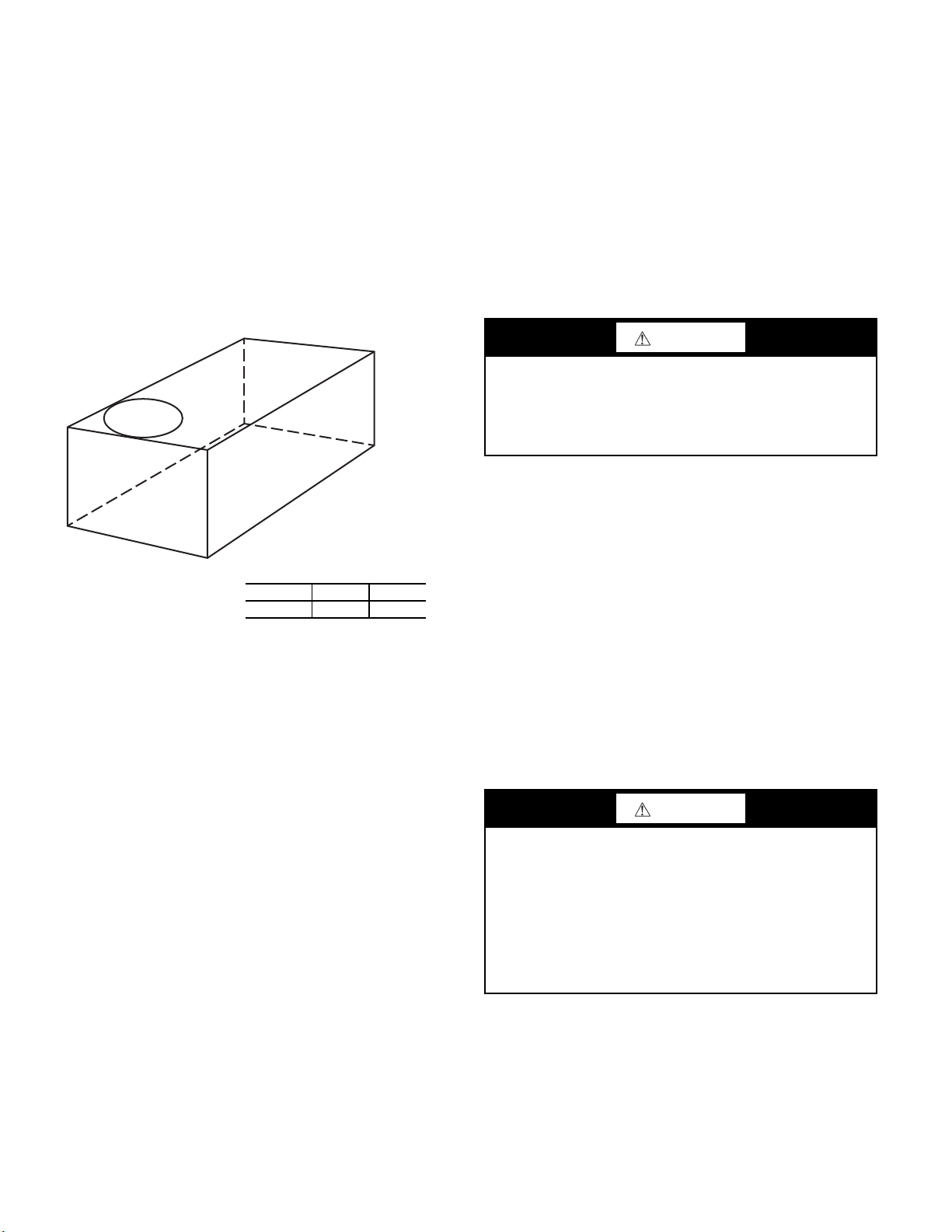
Step 5 — Field Fabricate Ductwork
Cabinet return-air static pressure (a negative condition) shall
not exceed 0.35 in. wg (87 Pa) with economizer or 0.45 in. wg
(112 Pa) without economizer.
For vertical ducted applications, secure all ducts to roof curb
and building structure. Do not connect ductwork to unit.
Fabricate supply ductwork so that the cross sectional dimensions are equal to or greater than the unit supply duct opening
dimensions for the first 18-in. (458 mm) of duct length from
the unit basepan.
Insulate and weatherproof all external ductwork, joints, and
roof openings with counter flashing and mastic in accordance
with applicable codes.
Ducts passing through unconditioned spaces must be insulated
and covered with a vapor barrier.
If a plenum return is used on a vertical unit, the return should
be ducted through the roof deck to comply with applicable fire
codes.
A minimum clearance is not required around ductwork.
Step 6 — Rig and Place Unit
CAUTION
PROPERTY DAMAGE HAZARD
Failure to follow this caution may result in damage to roof-
ing materials.
Membrane roofs can be cut by sharp sheet metal edges. Be
careful when placing any sheet metal parts on such roof.
Keep unit upright and do not drop. Spreader bars are required.
Rollers may be used to move unit across a roof. Rigging materials under unit (cardboard or wood) must be removed PRIOR to
placing the unit on the roof curb. Level by using unit frame as a
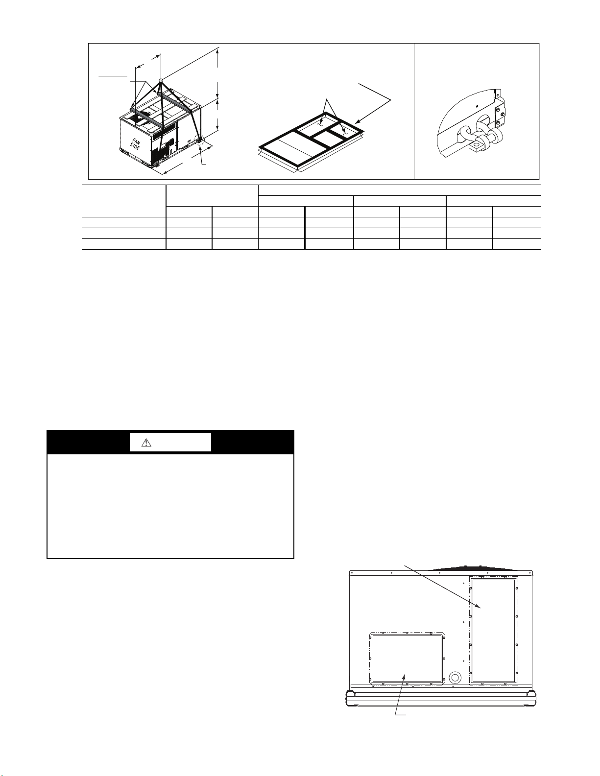
reference. See Table 2 and Fig. 9 for additional information.
Lifting holes are provided in base rails as shown in Fig. 9. Refer to rigging instructions on unit.
Rigging materials under unit (cardboard to prevent base pan
damage) must be removed PRIOR to placing the unit on the
roof curb.
When using the standard side drain connection, ensure the red
plug in the alternate bottom connection is tight. Do this before
setting the unit in place. The red drain plug an be tightened
1
with a
/2-in. square socket drive extension. For further details,
see “Step 12 — Install External Condensate Trap and Line” on
page 18.
Before setting the unit onto the curb, recheck gasketing on
curb.
CAUTION
UNIT DAMAGE HAZARD
Failure to follow this caution may result in equipment damage.
All panels must be in place when rigging. Unit is not de-
signed for handling by fork truck when packaging is removed.
If using top crate as spreader bar, once unit is set, carefully
lower wooden crate off building roof top to ground. Ensure
that no people or obstructions are below prior to lowering
the crate.
12
POSITIONING ON CURB
DETAIL "A"
PLACE ALL SEAL STRIP IN PLACE
BEFORE PLACING UNIT ON ROOF CURB.
DUCT END
SEE DETAIL "A"
"A"
(914-1371)
36"- 54"
"C"
"B"
SPREADER
BARS
REQUIRED
UNIT
MAX WEIGHT
DIMENSIONS
ABC
lb kg in. mm in. mm in. mm
581J*04 760 345 74.5 1890 38.0 965 33.5 850
581J*05 895 407 74.5 1890 38.0 965 41.5 1055
581J*06 930 423 74.5 1890 37.5 955 41.5 1055
NOTES:
1. SPREADER BARS ARE REQUIRED. Top damage will occur if spreader bars are not used.
2. Dimensions in () are in millimeters.
3. Hook rigging shackles through holes in base rail, as shown in Detail A. Holes in base rails are centered around the unit center of
gravity. Use wooden top to prevent rigging straps from damaging unit.
REMOVABLE HORIZONTAL
SUPPLY DUCT OPENING COVER
REMOVABLE HORIZONTAL
RETURN DUCT OPENING COVER
Position unit on roof curb so that the following clearances are
maintained:
and the base rail inside the front and rear, 0.0-in. clearance between the roof curb and the base rail inside on the duct end of
the unit. This will result in the distance between the roof curb
and the base rail inside on the condenser end of the unit being
approximately
Although unit is weatherproof, guard against water from higher
level runoff and overhangs.
UNIT DAMAGE HAZARD
Failure to follow this caution may result in equipment damage.
All panels must be in place when rigging. Unit is not de-
signed for handling by fork truck when packaging is removed.
If using top crate as spreader bar, once unit is set, carefully
lower wooden crate off building roof top to ground. Ensure
that no people or obstructions are below prior to lowering
the crate.
Flue vent discharge must have a minimum horizontal clearance
of 4 ft (1220 mm) from electric and gas meters, gas regulators,
and gas relief equipment. Minimum distance between unit and
other electrically live parts is 48-in. (1220 mm).
Flue gas can deteriorate building materials. Orient unit such
that flue gas will not affect building materials. Locate mechanical draft system flue assembly at least 48-in. (1220 mm) from
an adjacent building or combustible material.
NOTE: Installation of accessory flue discharge deflector kit will
reduce the minimum clearance to combustible material to 18-in.
(460 mm).
After unit is in position, remove rigging skids and shipping
materials.
Fig. 9 — Rigging Details
1
/4-in. (6.4 mm) clearance between the roof curb
1
/4-in. (6.4 mm).
CAUTION
Step 7 — Convert to Horizontal and Connect Ductwork (When Required)
Unit is shipped in the vertical duct configuration. Unit without
factory-installed economizer or return-air smoke detector
option may be field-converted to horizontal ducted
configuration. To convert to horizontal configuration, remove
screws from side duct opening covers (see Fig. 10) and remove
covers. Use the screws to install the covers on vertical duct
openings with the insulation-side down. The panels must be
inserted into the notches on the basepan to properly seal. The
notches are covered by the tape used to secure the insulation to
the basepan and are not easily seen. See Fig. 11 for position of
the notches in the basepan. Seals around duct openings must be
tight. Secure with screws as shown in Fig. 12. Cover seams
with foil duct tape.
Field-supplied flanges should be attached to horizontal duct
openings and all ductwork should be secured to the flanges. Insulate and weatherproof all external ductwork, joints, and roof
or building openings with counter flashing and mastic in accordance with applicable codes.
Do not cover or obscure visibility to the unit’s informative data
plate when insulating horizontal ductwork.
13
Fig. 10 — Horizontal Conversion Panels
NOTCHES
SCREWS
DUCT COVERS
SHEET METAL
FACE UP
BASEPAN
FILTER ACCESS PANEL
OUTDOOR-AIR OPENING AND
INDOOR COIL ACCESS PANEL
COMPRESSOR
ACCESS PANEL
HOOD PARTS
PLASTIC TIE WRAP
QTY (2)
SCREWS FOR
METAL TRAY
QTY (2)
BASEPAN
NOTCHES
Fig. 12 — Horizontal Duct Panels In Place
Step 8 — Install Outside Air Hood
ECONOMIZER AND TWO POSITION DAMPER HOOD PACKAGE REMOVAL AND SETUP (FACTORY OPTION)
NOTE: Economizer and two position damper are not available
as factory-installed options for single phase (-J voltage code)
models.
1. The hood is shipped in knock-down form and must be
field assembled. The indoor coil access panel is used as
the hood top while the hood sides, divider and filter are
packaged together, attached to a metal support tray using
plastic stretch wrap, and shipped in the return air compartment behind the indoor coil access panel. The hood assembly’s metal tray is attached to the basepan and also
attached to the damper using two plastic tie-wraps.
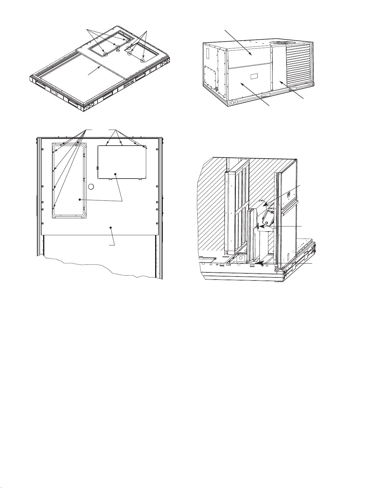
2. To gain access to the hood, remove the filter access panel.
See Fig. 13.
Fig. 11 — Location of Notches
Fig. 13 — Typical Access Panel Locations
3. Locate the (2) screws holding the metal tray to the basepan
and remove. Locate and cut the (2) plastic tie-wraps securing the assembly to the damper. See Fig. 14. Be careful to
not damage any wiring or cut tie-wraps securing any wiring.
Fig. 14 — Economizer and Two-Position Damper Hood
Parts Location
4. Carefully lift the hood assembly (with metal tray) through the
filter access opening and assemble per the steps outlined in
the Economizer Hood and Two-Position Hood section.
ECONOMIZER AND TWO-POSITION HOOD
NOTE: If the power exhaust accessory is to be installed on the
unit, the hood shipped with the unit will not be used and must be
discarded. Save the aluminum filter for use in the power exhaust
hood assembly.
1. The indoor coil access panel will be used as the top of the
hood. Remove the screws along the sides and bottom of
the indoor coil access panel. See Fig. 15.
14
 Loading...