

Bryant 581J-04A, Preferred Series, 581J-06A, 581J-05A Installation Instructions Manual
Preferred Series
581J 04-06
Single Package Rooftop Gas Heat/Electric Cooling Unit with
®
Puron
(R-410A) Refrigerant
Installation Instructions
CONTENTS
Page
GENERAL . . . . . . . . . . . . . . . . . . . . . . . . . . . . . . . . . . . . . . . . . . 1
SAFETY CONSIDERATIONS . . . . . . . . . . . . . . . . . . . . . . . . . . 1
Rated Indoor Airflow (cfm). . . . . . . . . . . . . . . . . . . . . . . . . 2
Pre-Installation . . . . . . . . . . . . . . . . . . . . . . . . . . . . . . . . . . 2
INSTALLATION. . . . . . . . . . . . . . . . . . . . . . . . . . . . . . . . . . . . . 6
Jobsite Survey . . . . . . . . . . . . . . . . . . . . . . . . . . . . . . . . . . . 6
Step 1 — Plan for Unit Location. . . . . . . . . . . . . . . . . . . . .6
Step 2 — Plan for Sequence of Unit Installation . . . . . . . .7
Step 3 — Inspect Unit . . . . . . . . . . . . . . . . . . . . . . . . . . . . . 7
Step 4 — Provide Unit Support. . . . . . . . . . . . . . . . . . . . . . 7
Step 5 — Field Fabricate Ductwork . . . . . . . . . . . . . . . . . . 9
Step 6 — Rig and Place Unit. . . . . . . . . . . . . . . . . . . . . . . . 9
Step 7 — Convert to Horizontal and Connect
Ductwork. . . . . . . . . . . . . . . . . . . . . . . . . . . . . . . . . . .10
Step 8 — Install Outside Air Hood . . . . . . . . . . . . . . . . . . 11
Step 9 — Relocate Latch (Units with Hinged Panels
Only) . . . . . . . . . . . . . . . . . . . . . . . . . . . . . . . . . . . . . . 12
Step 10 — Install Flue Hood . . . . . . . . . . . . . . . . . . . . . . . 12
Step 11 — Install Gas Piping . . . . . . . . . . . . . . . . . . . . . .12
Step 12 — Install External Condensate Trap and Line . . . 14
Step 13 — Make Electrical Connections. . . . . . . . . . . . . . 15
Perfect Humidity™ System Control Connections. . . . . . . 19
EconoMi$er
Low Ambient Control (Factory Option) . . . . . . . . . . . . . .34
RTU Open Controller System . . . . . . . . . . . . . . . . . . . . . .36
Field Connections . . . . . . . . . . . . . . . . . . . . . . . . . . . . . . . 40
Communication Wiring — Protocols . . . . . . . . . . . . . . . . 43
Local Access . . . . . . . . . . . . . . . . . . . . . . . . . . . . . . . . . . . 44
Outdoor Air Enthalpy Control (P/N 33CSENTHSW) . . . 45
Smoke Detectors . . . . . . . . . . . . . . . . . . . . . . . . . . . . . . . . 46
Step 14 — Adjust Factory Installed Options. . . . . . . . . . . 47
Step 15 — Install Accessories. . . . . . . . . . . . . . . . . . . . . .47
Step 16 — Check Belt Tension . . . . . . . . . . . . . . . . . . . . .47
Pre-Start and Start-Up . . . . . . . . . . . . . . . . . . . . . . . . . . . . 48
START-UP CHECKLIST . . . . . . . . . . . . . . . . . . . . . . . . . . . CL-1
®
X (Factory-Installed Option) . . . . . . . . . . . 21
GENERAL
See Fig. 1 for 581J model number nomenclature. See Fig. 2
for unit dimensional drawings. Figure 3 shows service clearance dimensions.
SAFETY CONSIDERATIONS
Improper installation, adjustment, alteration, service, maintenance, or use can cause explosion, fire, electrical shock or
other conditions which may cause personal injury or property
damage. Consult a qualified installer, service agency, or your
distributor or branch for information or assistance. The
qualified installer or agency must use factory-authorized kits
or accessories when modifying this product. Refer to the individual instructions packaged with the kits or accessories when
installing.
Follow all safety codes. Wear safety glasses and work
gloves. Use quenching cloths for brazing operations and have
a fire extinguisher available. Read these instructions thoroughly and follow all warnings or cautions attached to the
unit. Consult local building codes and appropriate national
electrical codes (in USA, ANSI/NFPA70, National Electrical
Code (NEC); in Canada, CSA C22.1) for special requirements.
It is important to recognize safety information. This is the
safety-alert symbol
and in instructions or manuals, be alert to the potential for personal injury.
Understand the signal words DANGER, WARNING, CAUTION, and NOTE. These words are used with the safety-alert
symbol. DANGER identifies the most serious hazards which will
result in severe personal injury or death. WARNING signifies
hazards which could result in personal injury or death. CAUTION is used to identify unsafe practices, which may result in
minor personal injury or product and property damage. NOTE is
used to highlight suggestions which will result in enhanced installation, reliability, or operation.
. When you see this symbol on the unit
WARNING
CARBON-MONOXIDE POISONING HAZARD
Failure to follow instructions could result in severe personal injury or death due to carbon-monoxide poisoning, if
combustion products infiltrate into the building.
Check that all openings in the outside wall around the vent
(and air intake) pipe(s) are sealed to prevent infiltration of
combustion products into the building.
Check that furnace vent (and air intake) terminal(s) are not
obstructed in any way during all seasons.
WARNING
Electrical shock can cause personal injury and death. Shut
off all power to this equipment during installation and service. There may be more than one disconnect switch. Tag
all disconnect locations to alert others not to restore power
until work is completed.
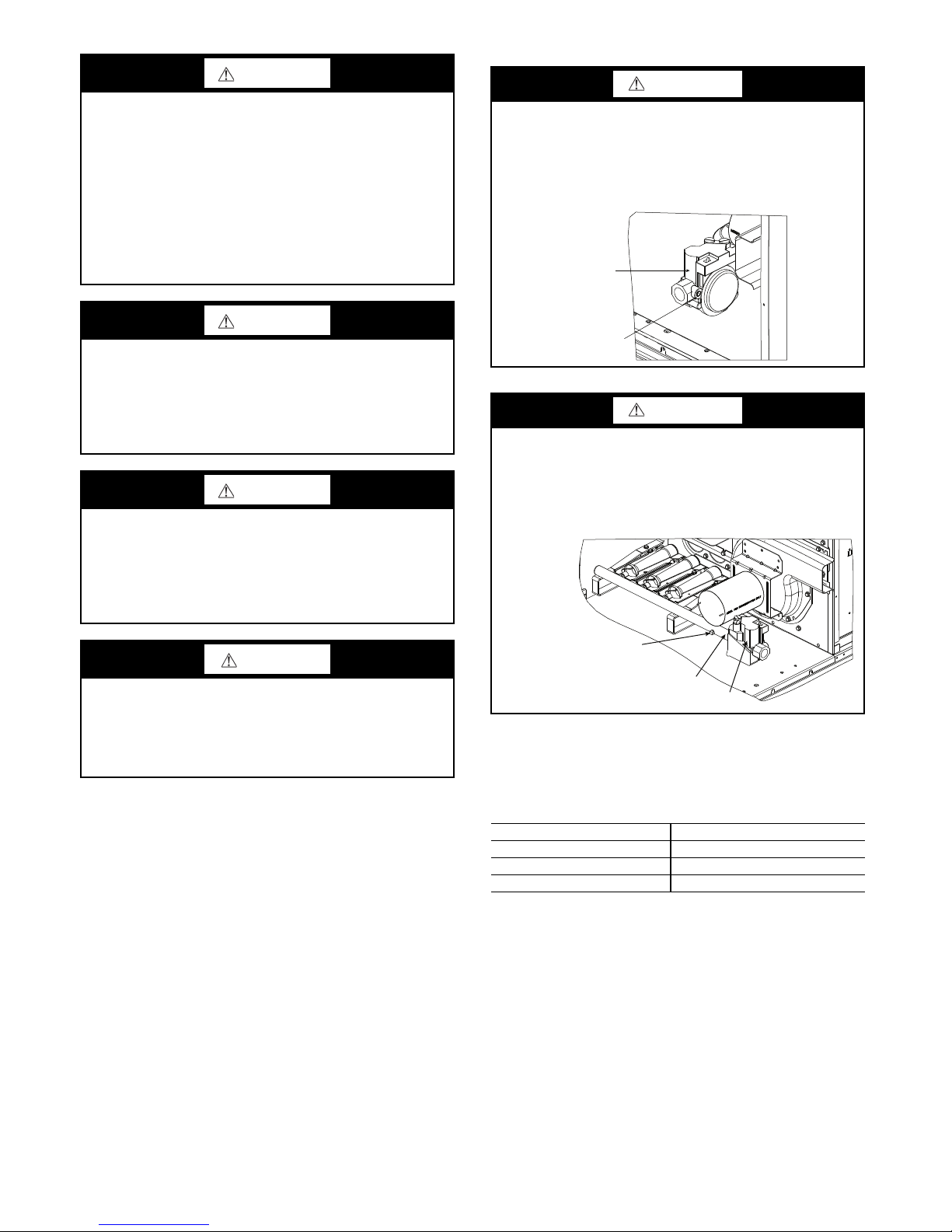
WARNING
MANIFOLD
GAS VALVE
MANIFOLD PRESSURE
TAP SET SCREW
Failure to follow this warning could result in personal
injury or death.
Disconnect gas piping from unit when leak testing at pressure greater than 0.5 psig (3450 Pa). Pressures greater than
0.5 psig (3450 Pa) will cause gas valve damage resulting in
hazardous condition. If gas valve is subjected to pressure
greater than 0.5 psig (3450 Pa), it must be replaced before
use. When pressure testing field-supplied gas piping at
pressures of 0.5 psig (3450 Pa) or less, a unit connected to
such piping must be isolated by closing the manual gas
valve.
WARNING
FIRE HAZARD
Failure to follow this warning could result in personal
injury, death, and/or property damage.
Inlet pressure tap set screw must be tightened and
pipe plug must be installed to prevent gas leaks.
GAS VALVE
1
/8 in. NPT
WARNING
Failure to follow this warning could cause personal injury,
death and/or equipment damage.
®
Puron
(R-410A) refrigerant systems operate at higher
pressures than standard R-22 systems. Do not use R-22 service equipment or components on Puron refrigerant equipment.
WARNING
Failure to follow this warning could cause personal injury
or death.
Relieve pressure and recover all refrigerant before system
repair or final unit disposal. Wear safety glasses and gloves
when handling refrigerants. Keep torches and other ignition sources away from refrigerants and oils.
CAUTION
Failure to follow this caution may result in personal injury.
Sheet metal parts may have sharp edges or burrs. Use care
and wear appropriate protective clothing, safety glasses and
gloves when handling parts and servicing air conditioning
equipment.
INLET PRESSURE
TAP SET SCREW
WARNING
FIRE HAZARD
Failure to follow this warning could result in personal
injury, death, and/or property damage.
Manifold pressure tap set screw must be tightened and
1
/8 in. NPT pipe plug must be installed to prevent gas leaks.
Rated Indoor Airflow (cfm) — Table 1 lists the rated
indoor airflow used for the AHRI efficiency rating for the
units covered in this document.
Table 1 — Rated Indoor Airflow
MODEL NUMBER FULL LOAD AIRFLOW (CFM)
581J*A/B/F04 1050
581J*A/B/F05 1400
581J*A/B/F06 1625
Pre-Installation — Complete the following checks before
installation.
1. Consult local building codes and the NEC (National
Electrical Code) ANSI/NFPA 70 for special installation requirements.
2. Determine unit location (from project plans) or select unit
location.
Check for possible overhead obstructions which may inter-
fere with unit lifting or rigging.
For model number nomenclature see Fig. 1. For unit dimen-
sions and service clearances see Fig. 2-4.
2
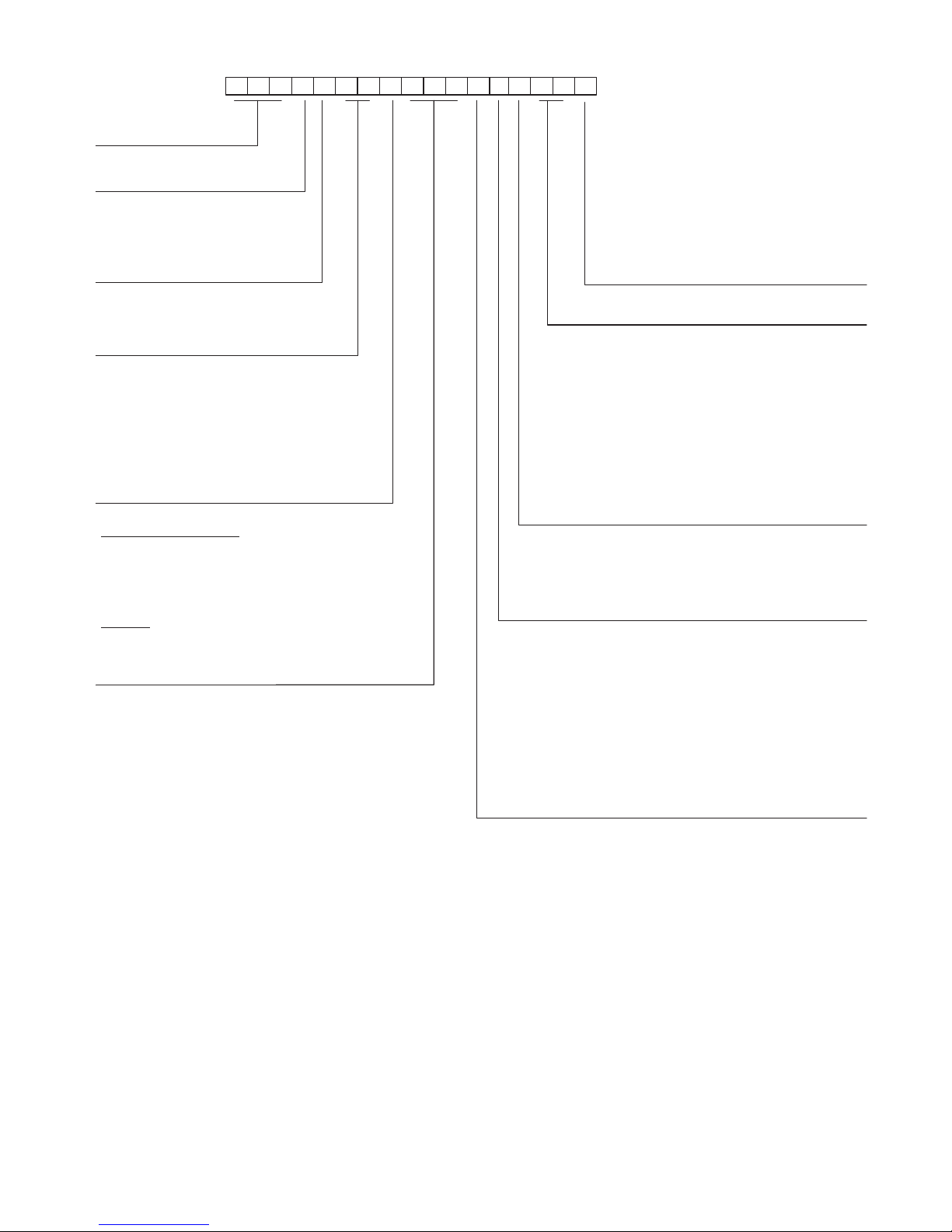
Unit Type
High Efficiency
Gas Heat RTU
Model
–
Puron Refrigerant Model
J
Voltage
E = 460-3-60
J = 208/230-1-60
P = 208/230-3-60
T = 575-3-60
1 2 3 4 5 6 7 8 9 1011121314151617
5 8 1 J E 0 6 A 0 7 2 A 0 B 0 A
A
Packaging and 2-Speed Indoor Fan
Motor
A = Standard Packaging, electro mech. controls
that require W7212 EconoMi$er IV
B = LTL Packaging, electro mech. controls that
require W7212 EconoMi$er IV
C = Standard Packaging, electro mech. controls
that require W7220 EconoMi$er X
D = Standard Packaging and 2-Speed Indoor Fan
Motor (VFD) Controller
E = LTL Packaging, and 2-Speed Indoor Fan
Motor (VFD) Controller
F = LTL Packaging, electro mech. controls that
require W7220 EconoMi$er X
Cooling Tons
04 - 3 ton
05 - 4 ton
06 - 5 ton
Refrig. System/Gas Heat Options
A = Standard One Stage cooling models/Nat. Gas Heat
B = Standard One Stage cooling models/Low NO
C = Standard One Stage cooling models/SS HX Heat
Heat
x
G = Standard One Stage cooling models and Perfect
Humidity™
H = Standard One Stage cooling/Low NOx Heat and
Perfect Humidity
J = Standard One Stage cooling/SS HX Heat and
Perfect Humidity
Heat Level Input
Standard/Stainless Steel
072 = 72,000 (1 Phase = 65,000) 180 = 180,000
115 = 115,000 (1 Phase = 90,000) 224 = 224,000
125 = 125,000 240 = 240,000
150 = 150,000 (1 Phase = 130,000) 250 = 250,000
Low NOx
060 = 60,000
090 = 90,000
120 = 120,000
Note: On single phase (-J voltage code) models, the
following are not available as a factory installed option:
- Perfect Humidity
- Coated Coils or Cu Fin Coils
- Louvered Hail Guards
- Economizer or 2 Position Damper
- Powered 115 Volt Convenience Outlet
Factory Installed Options
Outdoor Air Options
A = None
B = Temp Econo, Baro Relief, Standard Leak
(W7212 or W7220)
H = Enthalpy Econo, Baro Relief, Standard Leak
(W7212 or W7220)
E = Temp Econo, Baro Relief, Standard Leak w/CO
(W7212 or W7220)
L = Enthalpy Econo, Baro Relief, Standard Leak w/CO
(W7212 or W7220)
Q = Motorized 2 Position Damper
U = Temp Econo, Baro Relief, Ultra Low Leak, (W7220)
W = Enthalpy Econo, Baro Relief, Ultra Low Leak, (W7220)
Indoor Fan Options 3,4,5 Ton Models Only
0 = Electric (Direct) Drive x13 Motor
–
2 = Medium Static Option
3 = High Static Option
Belt Drive
–
Belt Drive
See price page details for specific Perfect Humidity
Coil Options (outdoor-indoor-hail guard)
A = Al/Cu - Al/Cu
B = Precoat Al/Cu - Al/Cu
C = E-coat Al/Cu - Al/Cu
D = E-coat Al/Cu - E-coat Al/Cu
E = Cu/Cu - Al/Cu
F = Cu/Cu - Cu/Cu
M = Al/Cu - Al/Cu – Louvered Hail Guards
N = Precoat Al/Cu - Al/Cu – Louvered Hail Guards
P = E-coat Al/Cu - Al/Cu – Louvered Hail Guards
Q = E-coat Al/Cu - E-coat Al/Cu – Louvered Hail Guards
R = Cu/Cu - Al/Cu – Louvered Hail Guards
S = Cu/Cu - Cu/Cu – Louvered Hail Guards
2
2
Fig. 1 — 581J 04-06 Model Number Nomenclature (Example)
3
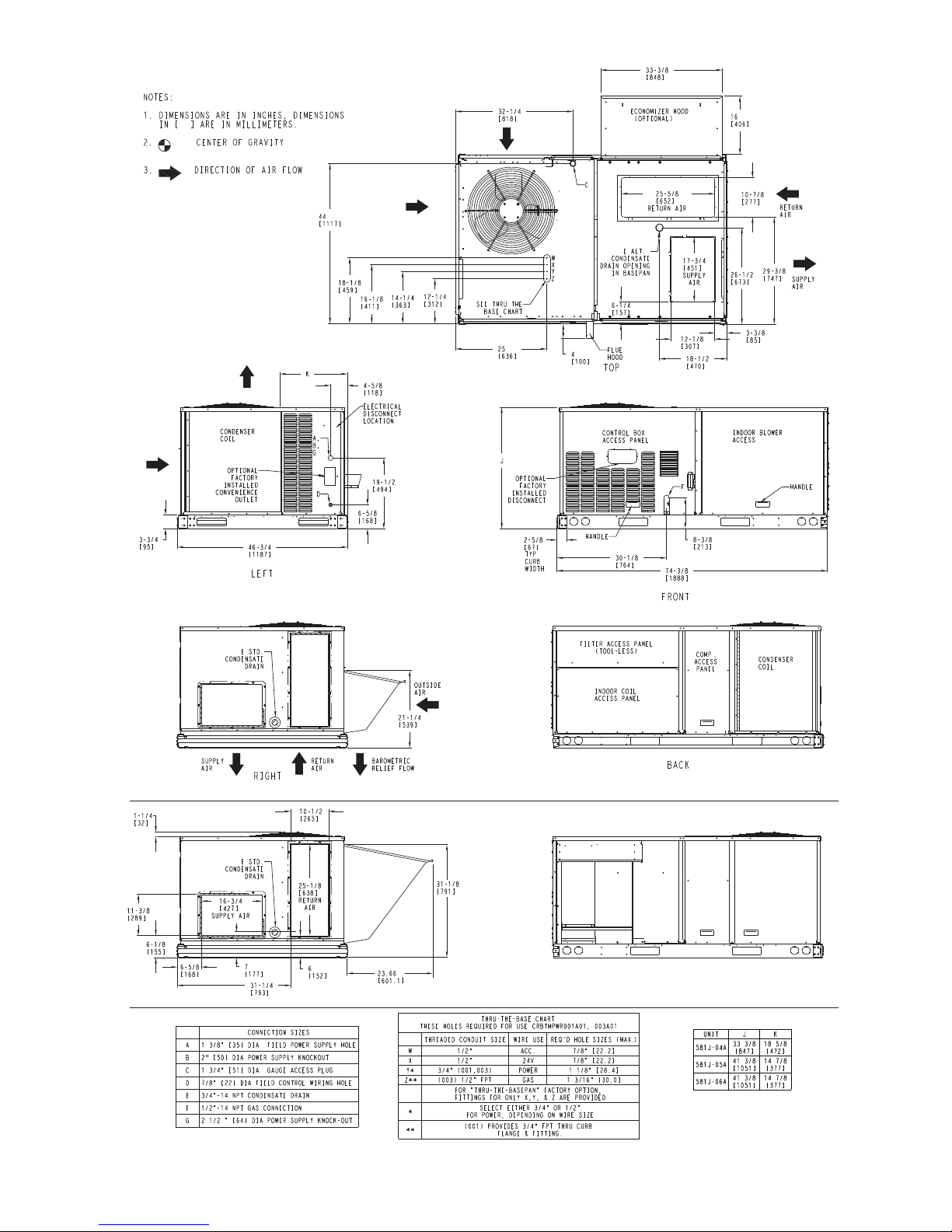
Vertical Connections / Economizer
Horizontal Connections / Economizer
Fig. 2 — Unit Dimensional Drawing
4
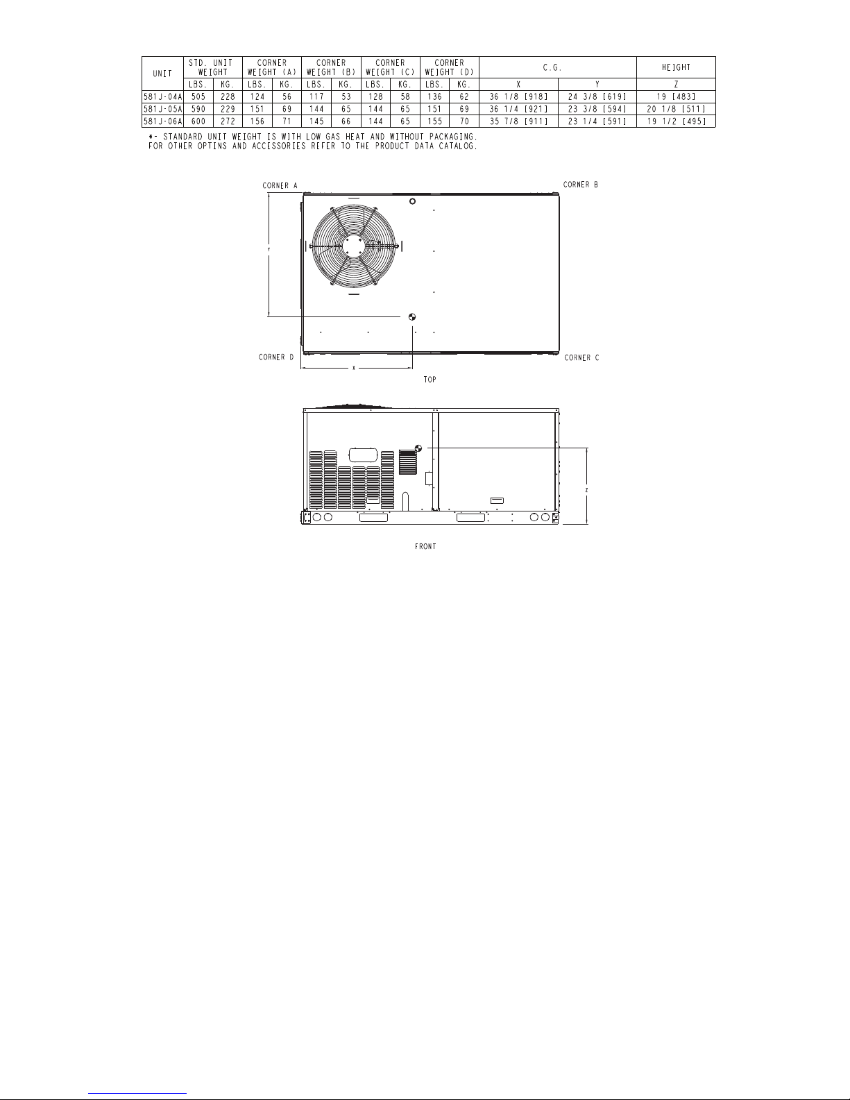
Fig. 2 — Unit Dimensional Drawing (cont)
5
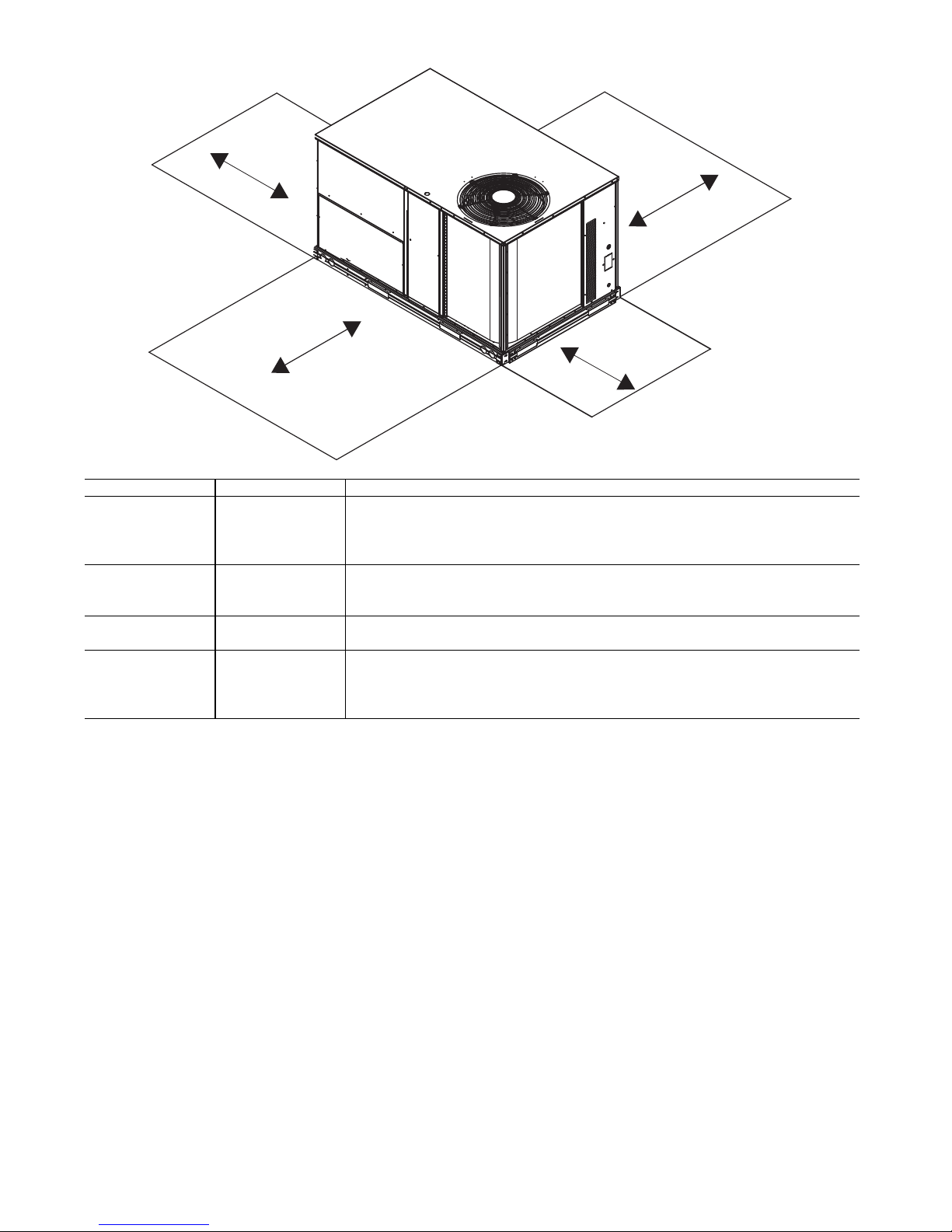
Fig. 3 — Service Clearance Dimensional Drawing
C
B
A
D
LOCATION DIMENSION CONDITION
A
48 in. (1219 mm) Unit disconnect is mounted on panel
18 in. (457 mm) No disconnect, convenience outlet option
18 in. (457 mm) Recommended service clearance
12 in. (305 mm) Minimum clearance
B
40 in. (1067 mm) Surface behind servicer is grounded (e.g., metal, masonry wall)
36 in. (914 mm) Surface behind servicer is electrically non-conductive (e.g., wood, fiberglass)
Special Check sources of flue products within 10 ft (3 m) of unit fresh air intake hood
C
36 in. (914 mm) Side condensate drain is used
18 in. (457 mm) Minimum clearance
D
48 in. (1219 mm) No flue discharge accessory installed, surface is combustible material
42 in. (1067 mm) Surface behind servicer is grounded (e.g., metal, masonry wall)
36 in. (914 mm) Surface behind servicer is electrically non-conductive (e.g., wood, fiberglass)
Special Check for adjacent units or building fresh air intakes within 10 ft (3 m) of this unit’s flue outlet
INSTALLATION
Jobsite Survey —
installation.
1. Consult local building codes and the NEC (National
Electrical Code) ANSI/NFPA 70 for special installation
requirements.
2. Determine unit location (from project plans) or select
unit location.
3. Check for possible overhead obstructions which may
interfere with unit lifting or rigging.
Complete the following checks before
Step 1 — Plan for Unit Location — Select a location
for the unit and its support system (curb or other) that provides for the minimum clearances required for safety. This
includes the clearance to combustible surfaces, unit performance and service access below, around and above unit as
specified in unit drawings. See Fig. 3.
NOTE: Consider also the effect of adjacent units.
block the combustion intake or flue outlet.
Class A, B, or C roof-covering material when roof curb is
used.
Be sure that unit is installed such that snow will not
Unit may be installed directly on wood flooring or on
6
Do not install unit in an indoor location. Do not locate air
inlets near exhaust vents or other sources of contaminated
air. For proper unit operation, adequate combustion and
ventilation air must be provided in accordance with Section
5.3 (Air for Combustion and Ventilation) of the National
Fuel Gas Code, ANSI Z223.1 (American National Standards Institute) and NFPA (National Fire Protection Association) 54 TIA–54–84–1. In Canada, installation must be in
accordance with the CAN1–B149 installation codes for gas
burning appliances.
Although unit is weatherproof, avoid locations that permit water from higher level runoff and overhangs to fall
onto the unit.
Locate mechanical draft system flue assembly at least
4 ft (1.2 m) from any opening through which combustion
products could enter the building, and at least 4 ft (1.2 m)
from any adjacent building (or per local code). Locate the
flue assembly at least 10 ft (3.05 m) from an adjacent unit’s
fresh air intake hood if within 3 ft (0.91 m) of same elevation (or per local code). When unit is located adjacent to
public walkways, flue assembly must be at least 7 ft (2.1 m)
above grade.
Select a unit mounting system that provides adequate
height to allow installation of condensate trap per
requirements. Refer to Step 12 — Install External Condensate
Trap and Line on page 14 for required trap dimensions.
ROOF MOUNT — Check building codes for weight distribution requirements. Unit operating weights are shown in
Table 2.
Table 2 — Operating Weights
581J--
Base Unit 505 (229) 590 (268) 600 (272)
Economizer
Vertical 50 (23) 50 (23) 50 (23)
Horizontal 80 (36) 80 (36) 80 (36)
Perfect Humidity
Cu Fins 25 (11) 43 (20) 56 (25)
Powered Outlet 32 (15) 32 (15) 32 (15)
Curb
14 in. (356 mm) 110 (50) 110 (50) 110 (50)
24 in. (610 mm) 145 (66) 145 (66) 145 (66)
™
System 27 (10) 34 (13) 34 (13)
UNIT LB (KG)
04 05 06
Step 2 — Plan for Sequence of Unit Installation —
The support method used for this unit will dictate different
sequences for the steps of unit installation. For example, on
curb-mounted units, some accessories must be installed on the
unit before the unit is placed on the curb. Review the following
for recommended sequences for installation steps:
CURB-MOUNTED INSTALLATION
1. Install curb
2. Install field-fabricated ductwork inside curb
3. Install accessory thru-base service connection package
(affects curb and unit) (refer to accessory installation
instructions for details)
4. Prepare bottom condensate drain connection to suit
planned condensate line routing (refer to Step 12 —
Install External Condensate Trap and Line on page 14 for
details)
5. Rig and place unit
6. Install outdoor air hood
7. Install flue hood
8. Install gas piping
9. Install condensate line trap and piping
10. Make electrical connections
11. Install other accessories
PAD-MOUNTED INSTALLATION
1. Prepare pad and unit supports
2. Check and tighten the bottom condensate drain connection plug
3. Rig and place unit
4. Convert unit to side duct connection arrangement
5. Install field-fabricated ductwork at unit duct openings
6. Install outdoor air hood
7. Install flue hood
8. Install gas piping
9. Install condensate line trap and piping
10. Make electrical connections
11. Install other accessories
FRAME-MOUNTED INSTALLATION — Frame-mounted applications generally follow the sequence for a curb installation. Adapt the sequence as required to suit specific installation plan.
Step 3 — Inspect Unit — Inspect unit for transportation
damage. File any claim with transportation agency.
Confirm before installation of unit that voltage, amperage
and circuit protection requirements listed on unit data plate
agree with power supply provided.
On units with hinged panel option, check to be sure all
latches are snug and in closed position.
Locate the carton containing the outside air hood parts. Do
not remove carton until unit has been rigged and located in final position.
Step 4 — Provide Unit Support
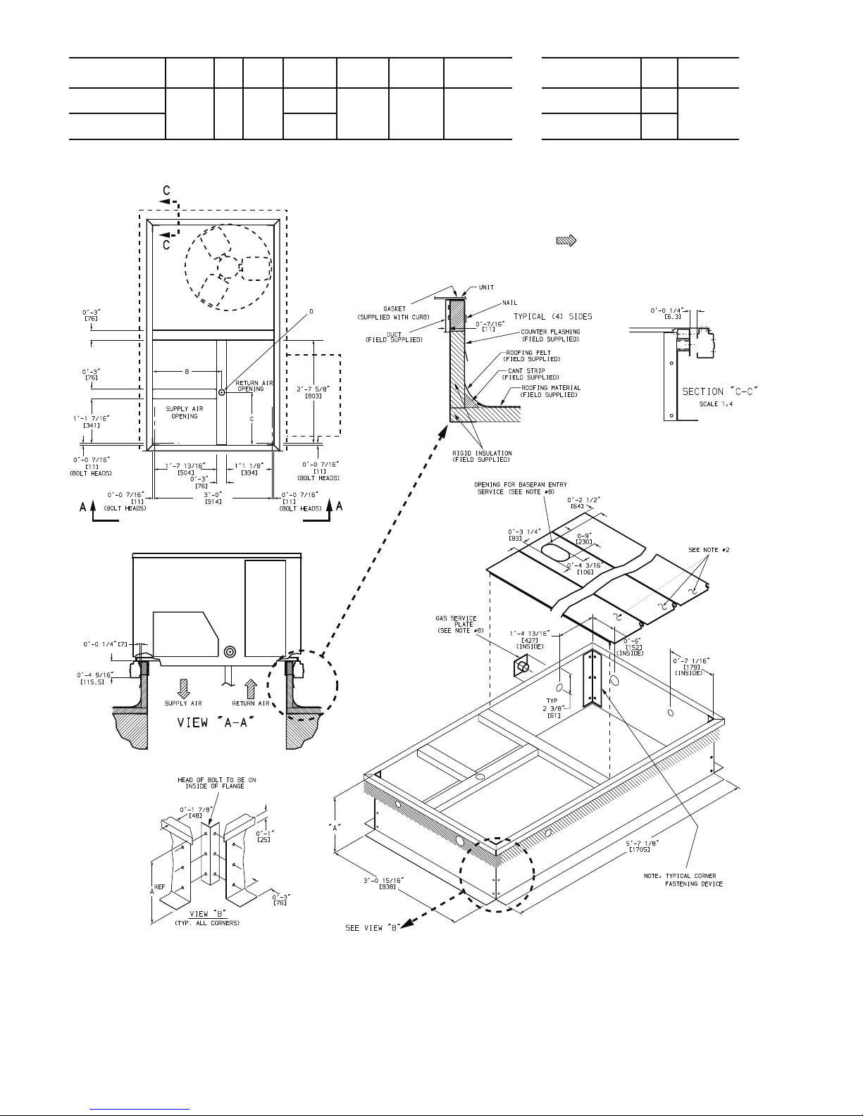
ROOF CURB MOUNT — Accessory roof curb details and
dimensions are shown in Fig. 4. Assemble and install accessory roof curb in accordance with instructions shipped with
the curb.
NOTE: The gasketing of the unit to the roof curb is critical for a
watertight seal. Install gasket supplied with the roof curb as
shown in Fig. 4. Improperly applied gasket can also result in air
leaks and poor unit performance.
Curb should be level. This is necessary for unit drain to
function properly. Unit leveling tolerances are shown in
Fig. 5. Refer to Accessory Roof Curb Installation Instructions
for additional information as required.
7
CONNECTOR
PKG. ACCY.
BC
D ALT
DRAIN
HOLE
GAS POWER CONTROL
ACCESSORY
POWER
CRBTMPWR001A01
1’-9
11
/16”
[551]
1
3
/4”
[44.5]
1’-4”
[406]
3
/4” [19]
NPT
CRBTMPWR003A01
3
/4” [19]
NPT
1
/2” [12.7]
NPT
1
/2” [12.7]
NPT
1
/2” [12.7]
NPT
ROOFCURB
ACCESSORY
AUNIT SIZE
CRRFCURB002A01
CRRFCURB001A01
1’-2”
[356]
2’-0”
[610]
581J*04-06
NOTES:
1. Roof curb accessory is shipped disassembled.
2. Insulated panels.
3. Dimensions in [ ] are in millimeters.
4. Roof curb: galvanized steel.
5. Attach ductwork to curb (flanges of duct rest on curb).
6. Service clearance: 4 ft on each side.
7. Direction of airflow.
8. Connector package CRBTMPWR001A01 is for
thru-the-curb type gas
.
CRBTMPWR003A01 is for thru-the-base type
gas connections.
Fig. 4 — Roof Curb Details
8
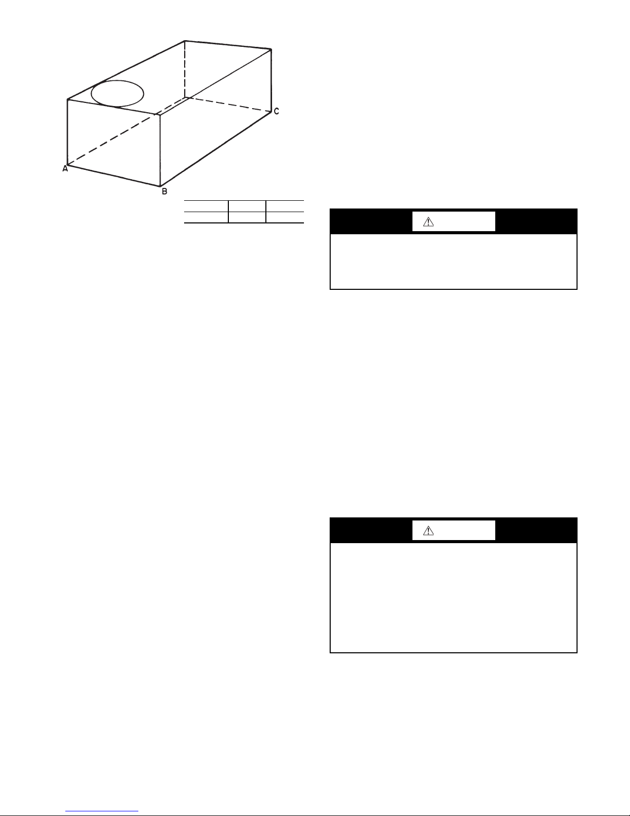
Fabricate supply ductwork so that the cross sectional di-
MAXIMUM ALLOWABLE
DIFFERENCE IN. (MM)
A-B B-C A-C
0.5 (13) 1.0 (25) 1.0 (25)
mensions are equal to or greater than the unit supply duct
opening dimensions for the first 18 in. (458 mm) of duct
length from the unit basepan.
Insulate and weatherproof all external ductwork, joints,
and roof openings with counter flashing and mastic in accordance with applicable codes.
Ducts passing through unconditioned spaces must be insulated and covered with a vapor barrier.
If a plenum return is used on a vertical unit, the return
should be ducted through the roof deck to comply with applicable fire codes.
A minimum clearance is not required around ductwork.
Step 6 — Rig and Place Unit
CAUTION
Fig. 5 — Unit Leveling Tolerances
Install insulation, cant strips, roofing felt, and counter
flashing as shown. Ductwork must be attached to curb and
not to the unit. The accessory thru-the-base power and gas
connection package must be installed before the unit is set
on the roof curb. If field-installed thru-the-roof curb gas
connections are desired, use factory-supplied
1
/2-in. pipe
coupling and gas plate assembly to mount the thru-the-roof
curb connection to the roof curb. Gas connections and power connections to the unit must be field-installed after the
unit is installed on the roof curb.
If electric and control wiring is to be routed through the
basepan, attach the accessory thru-the-base service connections to the basepan in accordance with the accessory installation instructions.
SLAB MOUNT (HORIZONTAL UNITS ONLY) —
Provide a level concrete slab that extends a minimum of 6 in.
(150 mm) beyond unit cabinet. Install a gravel apron in front of
condenser coil air inlet to prevent grass and foliage from
obstructing airflow.
NOTE: Horizontal units may be installed on a roof curb if
required.
ALTERNATE UNIT SUPPORT (IN LIEU OF CURB
OR SLAB MOUNT) — A non-combustible sleeper rail
can be used in the unit curb support area. If sleeper rails
cannot be used, support the long sides of the unit with a
minimum of 3 equally spaced 4-in. x 4-in. (102 mm x
102 mm) pads on each side.
Step 5 — Field Fabricate Ductwork — Cabinet re-
turn-air static pressure (a negative condition) shall not exceed 0.35 in. wg (87 Pa) with economizer or 0.45 in. wg
(112 Pa) without economizer.
For vertical ducted applications, secure all ducts to roof
curb and building structure. Do not connect ductwork to
unit.
Failure to follow this caution may result in damage to roofing materials.
Membrane roofs can be cut by sharp sheet metal edges. Be
careful when placing any sheet metal parts on such roof.
Keep unit upright and do not drop. Spreader bars are required. Rollers may be used to move unit across a roof. Rigging materials under unit (cardboard or wood) must be removed PRIOR to placing the unit on the roof curb. Level by
using unit frame as a reference. See Table 2 and Fig. 6 for
additional information.
Lifting holes are provided in base rails as shown in
Fig. 6. Refer to rigging instructions on unit.
Rigging materials under unit (cardboard to prevent base
pan damage) must be removed PRIOR to placing the unit on
the roof curb
When using the standard side drain connection, ensure
the red plug in the alternate bottom connection is tight. Do
this before setting the unit in place. The red drain plug an be
tightened with a
1
/2-in. square socket drive extension. For
further details, see “Step 12 — Install External Condensate
Trap and Line” on page 14.
Before setting the unit onto the curb, recheck gasketing
on curb.
CAUTION
Failure to follow this caution may result in injury or equipment damage.
All panels must be in place when rigging. Unit is not
designed for handling by fork truck when panels or packaging are removed.
If using top crate as spreader bar, once unit is set, carefully
lower wooden crate off building roof top to ground. Ensure
that no people or obstructions are below prior to lowering
the crate.
9
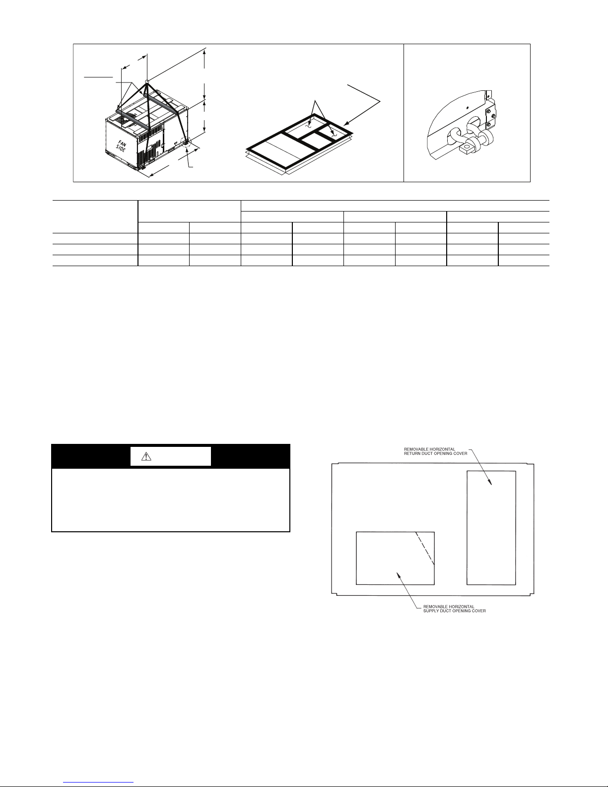
Fig. 6 — Rigging Details
DETAIL "A"
PLACE ALL SEAL STRIP IN PLACE
BEFORE PLACING UNIT ON ROOF CURB.
DUCT END
SEE DETAIL "A"
"A"
(914-1371)
36"- 54"
"C"
"B"
SPREADER
BARS
REQUIRED
NOTES:
1. SPREADER BARS ARE REQUIRED. Top damage will occur if spreader bars are not used.
2. Dimensions in () are in millimeters.
3. Hook rigging shackles through holes in base rail, as shown in Detail A. Holes in base rails are centered around the unit center of gravity. Use wooden
top to prevent rigging straps from damaging unit.
MAX WEIGHT
DIMENSIONS
UNIT ABC
LB KG in. MM in. MM in. MM
581J-04A 760 345 74.5 1890 38.0 965 33.5 850
581J-05A 895 407 74.5 1890 38.0 965 41.5 1055
581J-06A 930 423 74.5 1890 37.5 955 41.5 1055
POSITIONING ON CURB — Position unit on roof curb
so that the following clearances are maintained:
1
/4 in. (6.4
mm) clearance between the roof curb and the base rail inside the front and rear, 0.0 in. clearance between the roof
curb and the base rail inside on the duct end of the unit. This
will result in the distance between the roof curb and the base
rail inside on the condenser end of the unit being approxi-
1
mately
/4 in. (6.4 mm).
Although unit is weatherproof, guard against water from
higher level runoff and overhangs.
Step 7 — Convert to Horizontal and Connect
Ductwork (When Required) — Unit is shipped in the
vertical duct configuration. Unit without factory-installed
economizer or return air smoke detector option may be
field-converted to horizontal ducted configuration. To convert to horizontal configuration, remove screws from side
duct opening covers and remove covers. Using the same
screws, install covers on vertical duct openings with the insulation-side down. Seals around duct openings must be
tight. See Fig. 7.
CAUTION
Failure to follow this caution may result in equipment damage.
All panels must be in place when rigging. Unit is not
designed for handling by fork truck when panels or packaging are removed.
Flue vent discharge must have a minimum horizontal
clearance of 4 ft (1220 mm) from electric and gas meters,
gas regulators, and gas relief equipment. Minimum distance
between unit and other electrically live parts is 48 inches
(1220 mm).
Flue gas can deteriorate building materials. Orient unit
such that flue gas will not affect building materials. Locate
mechanical draft system flue assembly at least 48 in.
(1220 mm) from an adjacent building or combustible
material.
NOTE: Installation of accessory flue discharge deflector kit
will reduce the minimum clearance to combustible material to
18 in. (460 mm).
After unit is in position, remove rigging skids and shipping materials.
duct openings and all ductwork should be secured to the
flanges. Insulate and weatherproof all external ductwork,
joints, and roof or building openings with counter flashing
and mastic in accordance with applicable codes.
tive data plate when insulating horizontal ductwork.
10
Fig. 7 — Horizontal Conversion Panels
Field-supplied flanges should be attached to horizontal
Do not cover or obscure visibility to the unit’s informa-
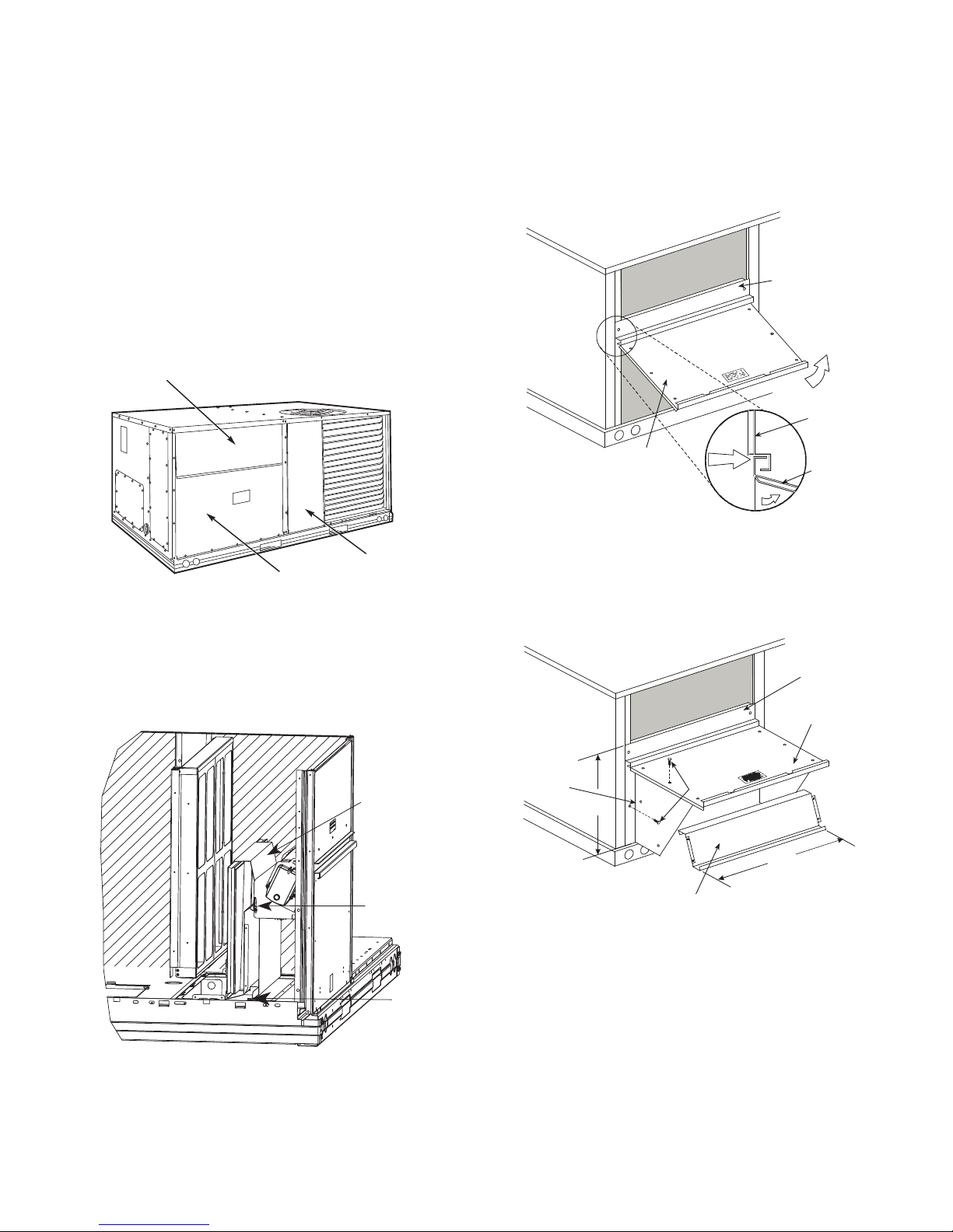
Step 8 — Install Outside Air Hood
FILTER ACCESS PANEL
OUTDOOR-AIR OPENING AND
INDOOR COIL ACCESS PANEL
COMPRESSOR
ACCESS PANEL
Hood Parts
Plastic Tie Wrap
Qty (2)
Screws for
Metal Tray
Qty (2)
TOP
PAN EL
INDOOR
COIL
ACCESS
PAN EL
INDOOR
COIL
ACCESS
PAN EL
CAULK
HERE
TOP
PAN EL
ECONOMIZER AND TWO POSITION DAMPER
HOOD PACKAGE REMOVAL AND SETUP (FACTORY OPTION)
NOTE: Economizer and two position damper are not available
as factory installed options for single phase (-3 voltage code)
models.
The hood is shipped in knock-down form and must be
field assembled. The indoor coil access panel is used as the
hood top while the hood sides, divider and filter are packaged together, attached to a metal support tray using plastic
stretch wrap, and shipped in the return air compartment behind the indoor coil access panel. The hood assembly’s metal tray is attached to the basepan and also attached to the
damper using two plastic tie-wraps.
1. To gain access to the hood, remove the filter access
panel. See Fig. 8.
ECONOMIZER AND TWO-POSITION HOOD
NOTE: If the power exhaust accessory is to be installed on the
unit, the hood shipped with the unit will not be used and must
be discarded. Save the aluminum filter for use in the power exhaust hood assembly.
1. The indoor coil access panel will be used as the top of
the hood. Remove the screws along the sides and bottom of the indoor coil access panel. See Fig. 10.
2. Locate the (2) screws holding the metal tray to the
Fig. 8 — Typical Access Panel Locations
basepan and remove. Locate and cut the (2) plastic tiewraps securing the assembly to the damper. See Fig. 9.
Be careful to not damage any wiring or cut tie-wraps
securing any wiring.
Fig. 9 — Economizer and Two-Position Damper Hood
3. Carefully lift the hood assembly (with metal tray)
Parts Location
through the filter access opening and assemble per the
steps outlined in the Economizer Hood and Two-Position Hood section.
Fig. 10 — Indoor Coil Access Panel Relocation
2. Swing out indoor coil access panel and insert the hood
sides under the panel (hood top). Use the screws provided to attach the hood sides to the hood top. Use
screws provided to attach the hood sides to the unit. See
Fig. 11.
TOP
PAN EL
INDOOR COIL
ACCESS PANEL
LEFT
HOOD
SIDE
19 1/16”
B
(483mm)
HOOD DIVIDER
SCREW
33 3/8”
(848mm)
Fig. 11 — Economizer Hood Construction
3. Remove the shipping tape holding the economizer
barometric relief damper in place (economizer only).
4. Insert the hood divider between the hood sides. See
Fig. 11 and 12. Secure hood divider with 2 screws on
each hood side. The hood divider is also used as the
bottom filter rack for the aluminum filter.
5. Open the filter clips which are located underneath the
hood top. Insert the aluminum filter into the bottom filter rack (hood divider). Push the filter into position past
the open filter clips. Close the filter clips to lock the filter into place. See Fig. 12.
6. Caulk the ends of the joint between the unit top panel
and the hood top.
7. Replace the filter access panel.
11
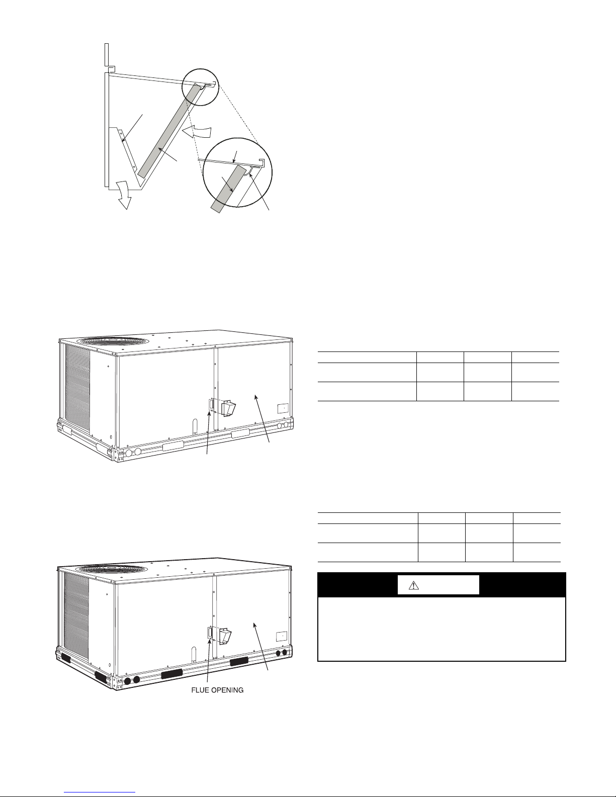
Fig. 12 — Economizer Filter Installation
DIVIDER
BAROMETRIC
RELIEF
CLEANABLE
ALUMINUM
FILTER
FILTER
HOOD
FILTER
CLIP
OUTSIDE
AIR
BLOWER
ACCESS
PANEL
FLUE OPENING
BLOWER
ACCESS
PANEL
Step 9 — Relocate Latch (Units with Hinged Panels
Only) —
compartment behind the hinged compressor door to location
shown in Fig. 13 after unit installation.
If the unit does not have hinged panels, skip this step and
continue at Step 10 below.
Relocate latch shipped inside the compressor
Step 11 — Install Gas Piping — Installation of the gas
piping must be accordance with local building codes and
with applicable national codes. In U.S.A., refer to NFPA 54/
ANSI Z223.1 National Fuel Gas Code (NFGC). In Canada,
installation must be accordance with the CAN/CSA B149.1
and CAN/CSA B149.2 installation codes for gas burning
appliances.
This unit is factory equipped for use with Natural Gas
fuel at elevations up to 2000 ft (610 m) above sea level. Unit
may be field converted for operation at elevations above
2000 ft (610 m) and/or for use with liquefied petroleum fuel. See accessory kit installation instructions regarding these
accessories.
NOTE: Furnace gas input rate on rating plate is for installation
up to 2000 ft (610 m) above sea level. In U.S.A. the input rating for altitudes above 2000 ft (610 m) must be derated by 4%
for each 1000 ft (305 m) above sea level. In Canada the input
rating must be derated by 10% for altitudes of 2000 ft (610 m)
to 4500 ft (1372 m) above sea level.
For natural gas applications, gas pressure at unit gas connection must not be less than 4 in. wg (996 Pa) or greater
than 13 in. wg (3240 Pa) while the unit is operating. On
581J*05-06 high-heat units, the gas pressure at unit gas connection must not be less than 5 in. wg (1245 Pa) or greater
than 13 in. wg (3240 Pa) while the unit is operating. See Table 3. For liquefied petroleum applications, the gas pressure
must not be less than 11 in. wg (2740 Pa) or greater than
13.6 in. wg (3390 Pa) at the unit connection.
Table 3 — Natural Gas Supply Line Pressure Ranges
Fig. 13 — Compressor Door Latch Location
Step 10 — Install Flue Hood — Flue hood is shipped
screwed to the basepan beside the burner compartment access panel. Remove from shipping location and using
screws provided, install flue hood and screen in location
shown in Fig. 14.
UNIT MODEL UNIT SIZE MIN. MAX.
581JD/E/L/M/S/R 04, 05, 06
581JF/N/T
(High Heat Units Only)
04, 05, 06
4.0 in. wg
(996 Pa)
5.0 in. wg
(1245 Pa)
13.0 in. wg
(3240 Pa)
13.0 in. wg
(3240 Pa)
The gas supply pipe enters the unit at the burner access
panel on the front side of the unit, through the long slot at
the bottom of the access panel. The gas connection to the
unit is made to the
1
/2-in. FPT gas inlet port on the unit gas
valve.
Manifold pressure is factory-adjusted for natural gas fuel
use. Adjust as required to obtain best flame characteristics.
See Table 4.
Table 4 — Natural Gas Manifold Pressure Ranges
UNIT MODEL UNIT SIZE HIGH FIRE LOW FIRE
581JD/E/L/M/S/R 04, 05, 06
581JF/N/T
(High Heat Units Only)
04, 05, 06
3.5 in. wg
(872 Pa)
3.5 in. wg
(872 Pa)
1.7 in. wg
(423 Pa)
1.7 in. wg
(423 Pa)
CAUTION
Failure to follow this caution may result in equipment damage.
When connecting the gas line to the unit gas valve, the
installer MUST use a backup wrench to prevent damage to
the valve.
Fig. 14 — Flue Hood Details
Install a gas supply line that runs to the unit heating section. Refer to the NFPA 54/NFGC or equivalent code for
gas pipe sizing data. Do not use a pipe size smaller than
1
/2-in. Size the gas supply line to allow for a maximum pressure drop of 0.5-in. wg (124 Pa) between gas regulator
source and unit gas valve connection when unit is operating
at high-fire flow rate.
12

The gas supply line can approach the unit in three ways:
X
BASE UNIT
BASE RAIL
ROOF
CURB
9” MINIMUM CLEARANCE
FOR PANEL REMOVAL
MANUAL GAS
SHUTOFF VALVE
*
GAS
REGULATOR
*
48” MINIMUM
DRIP LEG
PER NFGC
*
FIELD-FABRICATED
SUPPORT
*
FROM
GAS
METER
LEGEND *Field supplied.
NOTE: Follow all local codes.
NFGC —
National Fuel Gas
Code
STEEL PIPE NOMINAL
DIAMETERS (IN.)
SPACING OF SUPPORTS
X DIMENSION (FT.)
1
/
2
6
3
/4 or 1 8
1-
1
/4 or larger 10
9” (229mm) min
Union
Shut Off
Valve
Drip
Leg
Thru-Curb Adapter
Unit Base Rail
horizontally from outside the unit (across the roof), thrucurb/under unit basepan (accessory kit required), or through
unit basepan (factory option or accessory kit required). Consult accessory kit installation instructions for details on
these installation methods. Observe clearance to gas line
components per Fig. 15.
tend it through the access panel at the gas support bracket.
See Fig. 17.
Fig. 15 — Gas Piping Guide
(with Accessory Thru-the-Curb Service Connections)
FACTORY-OPTION THRU-BASE CONNECTIONS
(GAS CONNECTIONS) — This service connection kit
consists of a
electrical bulkhead connector and a
1
/2-in. NPT gas adapter fitting (brass), a 1/2-in.
3
/4-in. electrical bulkhead connector, all factory-installed in the embossed
(raised) section of the unit basepan in the condenser section.
See Fig. 16.
EMBOSSMENT
BRASS FITTING
FOR 3-6 TON UNITS
SUPPORT
BRACKET
Fig. 17 — Gas Line Piping for 3 to 5 Ton Units Only
Other hardware required to complete the installation of
the gas supply line includes a manual shutoff valve, a sediment trap (drip leg) and a ground-joint union. A pressure
regulator valve may also be required (to convert gas pressure from pounds to inches of pressure). The manual shutoff
valve must be located within 6 ft (1.83 m) of the unit. The
union, located in the final leg entering the unit, must be located at least 9 in. (230 mm) away from the access panel to
permit the panel to be removed for service. If a regulator
valve is installed, it must be located a minimum of 4 ft
(1220 mm) away from the unit’s flue outlet. Some municipal codes require that the manual shutoff valve be located
upstream of the sediment trap. See Fig. 18 and 19 for typical
piping arrangements for gas piping that has been routed
through the sidewall of the curb. See Fig. 20 for typical piping arrangement when thru-base is used. Ensure that all piping does not block access to the unit’s main control box or
limit the required working space in front of the control box.
LOW VOLTAGE
CONDUIT
CONNECTOR
HIGH VOLTAGE
CONDUIT
BRASS FITTING FOR 3 TO 6 TON UNITS.
Fig. 16 — Thru-Base Gas Connection Fittings
The thru-base gas connector has male and female
threads. The male threads protrude above the basepan of the
unit; the female threads protrude below the basepan.
Check tightness of connector lock nuts before connecting
gas piping.
Install a
ting. Attach a
16-in. (406 mm) (field-supplied) to the street elbow and ex-
1
/2-in. NPT street elbow on the thru-base gas fit-
1
/2-in. pipe nipple with minimum length of
CONNECTOR
Fig. 18 — Gas Piping, Typical Curb Sidewall Piping
(Example 1)
13
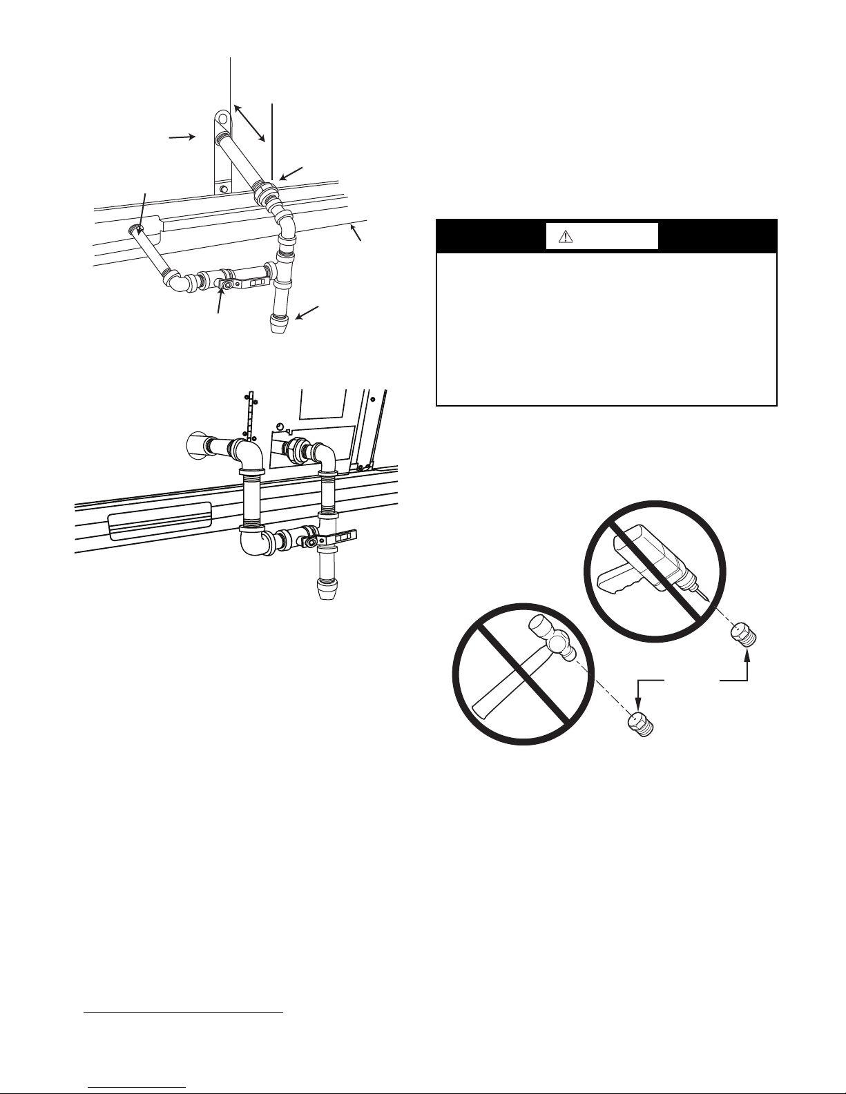
Fig. 19 — Gas Piping, Typical Curb Sidewall Piping
Drip
Leg
Shut Off
Valve
Union
Thru-Curb Adapter
Burner
Access
Panel
9” (229mm) min
Unit Base Rail
BURNER
ORIFICE
(Example 2)
disconnected from the gas valve during the testing of the piping
systems when test pressure is in excess of 0.5 psig (3450 Pa).
Pressure test the gas supply piping system at pressures equal to
or less than 0.5 psig (3450 Pa). The unit heating section must
be isolated from the gas piping system by closing the external
main manual shutoff valve and slightly opening the groundjoint union.
Check for gas leaks at the field-installed and factory-installed gas lines after all piping connections have been completed. Use soap-and-water solution (or method specified by
local codes and/or regulations).
WARNING
Failure to follow this warning could result in personal injury,
death and/or property damage.
• Connect gas pipe to unit using a backup wrench to
avoid damaging gas controls.
• Never purge a gas line into a combustion chamber.
• Never test for gas leaks with an open flame. Use a
commercially available soap solution made specifically
for the detection of leaks to check all connections.
• Use proper length of pipe to avoid stress on gas control
manifold.
NOTE: If orifice hole appears damaged or it is suspected to
have been redrilled, check orifice hole with a numbered drill bit
of correct size. Never redrill an orifice. A burr-free and squarely aligned orifice hole is essential for proper flame characteristics. See Fig. 21.
Fig. 20 — Gas Piping, Typical Thru-Base Connections
When installing the gas supply line, observe local codes
pertaining to gas pipe installations. Refer to the NFPA 54/
ANSI Z223.1 NFGC latest edition (in Canada, CAN/CSA
B149.1). In the absence of local building codes, adhere to
the following pertinent recommendations:
• Avoid low spots in long runs of pipe. Grade all pipe
1
/4 in. per every 15 ft (7 mm per every 5 m) to prevent
traps. Grade all horizontal runs downward to risers. Use
risers to connect to heating section and to meter.
• Protect all segments of piping system against physical
and thermal damage. Support all piping with appropriate
straps, hangers, etc. Use a minimum of one hanger every
6 ft (1.8 m). For pipe sizes larger than
ommendations of national codes.
• Apply joint compound (pipe dope) sparingly and only to
• Pressure-test all gas piping in accordance with local and
male threads of joint when making pipe connections. Use
only pipe dope that is resistant to action of liquefied
petroleum gases as specified by local and/or national
codes. If using PTFE (Teflon
is Double Density type and is labeled for use on gas
lines. Apply tape per manufacturer’s instructions.
national plumbing and gas codes before connecting pip-
1
) tape, ensure the material
ing to unit.
NOTE: Pressure test the gas supply system after the gas supply
piping is connected to the gas valve. The supply piping must be
1. Teflon is a registered trademark of DuPont.
1
/2 in., follow rec-
Fig. 21 — Orifice Hole
Step 12 — Install External Condensate Trap and
Line
The unit has one 3/4-in. condensate drain connection on
the end of the condensate pan and an alternate connection
on the bottom. See Fig. 22. Unit airflow configuration does
not determine which drain connection to use. Either drain
connection can be used with vertical or horizontal applications.
When using the standard side drain connection, ensure
the red plug in the alternate bottom connection is tight. Do
this before setting the unit in place. The red drain pan can be
tightened with a
To use the alternate bottom drain connection, remove the
red drain plug from the bottom connection (use a
square socket drive extension) and install it in the side drain
connection.
14
1
/2-in. square socket drive extension.
1
/2-in.
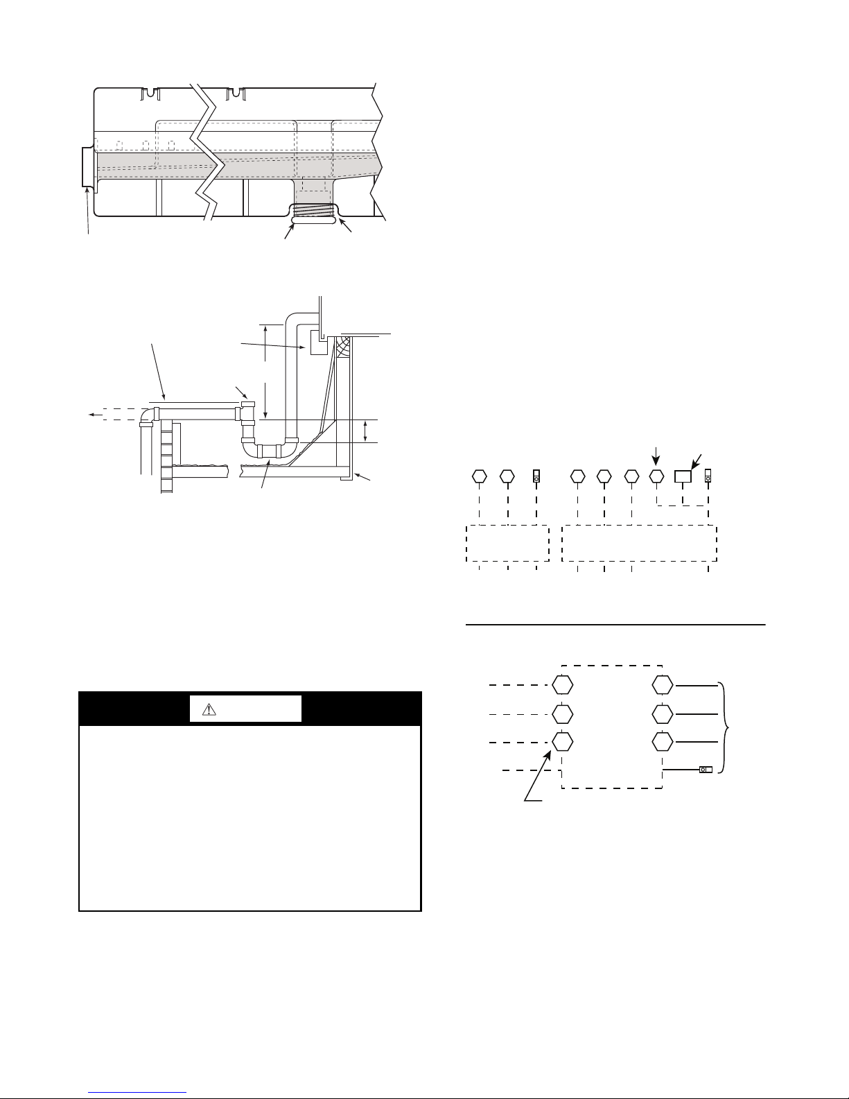
The piping for the condensate drain and external trap can
DRAIN
(FACTORY-INSTALLED)
PLUG
CONDENSATE PAN (SIDE VIEW)
STANDARD
SIDE DRAIN
ALTERNATE
BOTTOM DRAIN
NOTE: Trap should be deep enough to offset maximum unit static
difference. A 4 in. (102 mm) trap is recommended.
MINIMUM PITCH
1˝ (25 mm) PER
10´ (3 m) OF LINE
BASE RAIL
OPEN
VENT
TO ROOF
DRAIN
DRAIN PLUG
ROOF
CURB
SEE NOTE
3˝ (76 mm)
MIN
be completed after the unit is in place. See Fig. 23.
Fig. 22 — Condensate Drain Pan (Side View)
the source leads to the line side of the unit-mounted disconnect. (Check with local codes to ensure this method is acceptable in your area.) If a de-energize via unit disconnect
switch operation of the convenience outlet is desired, connect the source leads to the load side of the unit disconnect.
On a unit without a unit-mounted disconnect, connect the
source leads to compressor contactor C and indoor fan contactor IFC pressure lugs with unit field power leads.
See CONVENIENCE OUTLETS on page 16 for power
transformer connections.
Field power wires are connected to the unit at line-side
pressure lugs on compressor contactor C and indoor fan
contactor IFC (see wiring diagram label for control box
component arrangement) or at factory-installed option nonfused disconnect switch or HACR. Maximum wire size is
#2ga AWG (copper only) per pole on contactors and #2ga
AWG (copper only) per pole on optional disconnect or
HACR. See Fig. 24 and unit label diagram for field power
wiring connections.
NOTE: Unit may be equipped with short test leads (pigtails) on
the field line connection points on contactor C or optional disconnect switch. These leads are for factory-run test purposes
only; remove and discard before connecting field power wires
to unit connection points. Make field power connections directly to line connection pressure lugs only.
Units Without Disconnect or HACR Option
C
11 2 3
Equip
GR Lug
1-ph Belt Drive IFM
CIFC
11
13 13 23
or
TB
Direct Drive IFM
Equip
GR Lug
Fig. 23 — Condensate Drain Pan Piping Details
All units must have an external trap for condensate
drainage. Install a trap at least 4 in. (102 mm) deep and
protect against freeze-up. If drain line is installed downstream from the external trap, pitch the line away from the
unit at 1 in. per 10 ft (25 mm per 3 m) of run. Do not use a
pipe size smaller than the unit connection (
Step 13 — Make Electrical Connections
WARNING
Failure to follow this warning could result in personal injury
or death.
Do not use gas piping as an electrical ground. Unit cabinet must have an uninterrupted, unbroken electrical
ground to minimize the possibility of personal injury if an
electrical fault should occur. This ground may consist of
electrical wire connected to unit ground lug in control
compartment, or conduit approved for electrical ground
when installed in accordance with NEC (National Electrical Code); ANSI/NFPA 70, latest edition (in Canada, Ca-
nadian Electrical Code CSA [Canadian Standards Association] C22.1), and local electrical codes.
NOTE: Field-supplied wiring shall conform with the limitations of minimum 63°F (33°C) rise.
FIELD POWER SUPPLY — If equipped with optional
Powered Convenience Outlet, the power source leads to the
convenience outlet’s transformer primary are not factory
connected. Installer must connect these leads according to
required operation of the convenience outlet. If an alwaysenergized convenience outlet operation is desired, connect
3
/4 in.).
Disconnect
per
NEC
208/230-1-60
Ground
(GR)
L1
208/230-3-60
L2 L3
460-3-60
575-3-60
Disconnect
per
NEC
Ground
(GR)
Units With Disconnect or HACR Option
L1
L2
3 Phase Onl y 3 Phase Only
L3
Ground
(GR)
2
Optional
Disconnect
4
Switch
6
Disconnect factory test leads; discard.
1
3
5
Equip GR Lug
Fig. 24 — Power Wiring Connections
UNITS WITH FACTORY-INSTALLED NON-FUSED
DISCONNECT OR HACR — The factory-installed op-
tion non-fused disconnect (NFD) or HACR switch is located in a weatherproof enclosure located under the main control box. The manual switch handle and shaft are shipped in
the disconnect or HACR enclosure. Assemble the shaft and
handle to the switch at this point. Discard the factory test
leads (see Fig. 24).
15
Factory
Wiring

Failure to follow this caution could result in fire, intermit-
COPPER
WIRE ONLY
ELECTRIC
DISCONNECT
SWITCH
ALUMINUM
WIRE
CONVENIENCE
OUTLET GFCI
PWD-CO FUSE
SWITCH
PWD-CO TRANSFORMER
CONTROL BOX
ACCESS PANEL
tent operation, or unsatisfactory performance.
switch and air conditioning unit. Use only copper wire.
See Fig. 25.
UNITS WITHOUT FACTORY-INSTALLED NONFUSED DISCONNECT OR HACR — When installing
units, provide a disconnect switch per NEC (National Electrical Code) of adequate size. Disconnect sizing data is provided on the unit informative plate. Locate on unit cabinet
or within sight of the unit per national or local codes. Do not
cover unit informative plate if mounting the disconnect on
the unit cabinet.
ALL UNITS — All field wiring must comply with NEC
and all local codes. Size wire based on MCA (Minimum
Circuit Amps) on the unit informative plate. See Fig. 24 and
the unit label diagram for power wiring connections to the
unit power terminal blocks and equipment ground. Maximum wire size is #2ga AWG (copper only) per pole on contactors. See Fig. 24 and unit label diagram for field power
wiring connections.
tection device (fuse or breaker) per NEC Article 440 (or local codes). Refer to unit informative data plate for MOCP
(Maximum Over-Current Protection) device size.
NOTE: Units ordered with factory installed HACR do not need
an additional ground fault and short circuit over-current protective device unless required by local codes.
quirements.
voltage shown on the nameplate. If the 208/230v unit is to
be connected to a 208v power supply, the control transformer must be rewired by moving the black wire with the
female spade connector from the 230v connection and moving it to the 200v
the transformer. Refer to unit label diagram for additional
information. Field power wires will be connected at lineside pressure lugs on the power terminal block or at factoryinstalled option non-fused disconnect.
NOTE: Check all factory and field electrical connections for
tightness.
CAUTION
Do not connect aluminum wire between disconnect
Fig. 25 — Disconnect Switch and Unit
Provide a ground fault and short circuit over-current pro-
All field wiring must comply with the NEC and local re-
All units except 208/230v units are factory wired for the
1
/4-in.
1
/4-in. male terminal on the primary side of
CONVENIENCE OUTLETS
WARNING
Failure to follow this warning could result in personal injury
or death.
Units with convenience outlet circuits may use multiple disconnects. Check convenience outlet for power status before opening unit for service. Locate its disconnect
switch, if appropriate, and open it. Lock-out and tag-out
this switch, if necessary.
Two types of convenience outlets are offered on 581J
models: non-powered and unit-powered. Both types provide
a 125-volt GFCI (ground-fault circuit interrupter) duplex receptacle rated at 15A behind a hinged waterproof access
cover, located on the end panel of the unit. See Fig. 26.
NOTE: Unit powered convenience outlets are not available as
factory installed options for single phase (-J voltage code)
models.
Fig. 26 — Convenience Outlet Location
Installing Weatherproof Cover
— A weatherproof while-inuse cover for the factory-installed convenience outlets is now
required by UL standards. This cover cannot be factorymounted due its depth; it must be installed at unit installation.
For shipment, the convenience outlet is covered with a blank
cover plate.
The weatherproof cover kit is shipped in the unit’s control box. The kit includes the hinged cover, a backing plate,
and gasket.
WARNING
Failure to follow this warning could result in personal injury
or death.
Disconnect all power to unit and convenience outlet.
Lock-out and tag-out all power.
1. Remove the blank cover plate at the convenience out-
let; discard the blank cover.
2. Loosen the two screws at the GFCI duplex outlet, until
approximately
1/
in. (13 mm) under screw heads is
2
exposed. Press the gasket over the screw heads.
16
 Loading...