

Page 1
Bryant
Air Conditioning
COMMERCIAL
SINGLE PACKAGE ROOFTOP
GAS HEATING/ELECTRIC COOLING UNITS
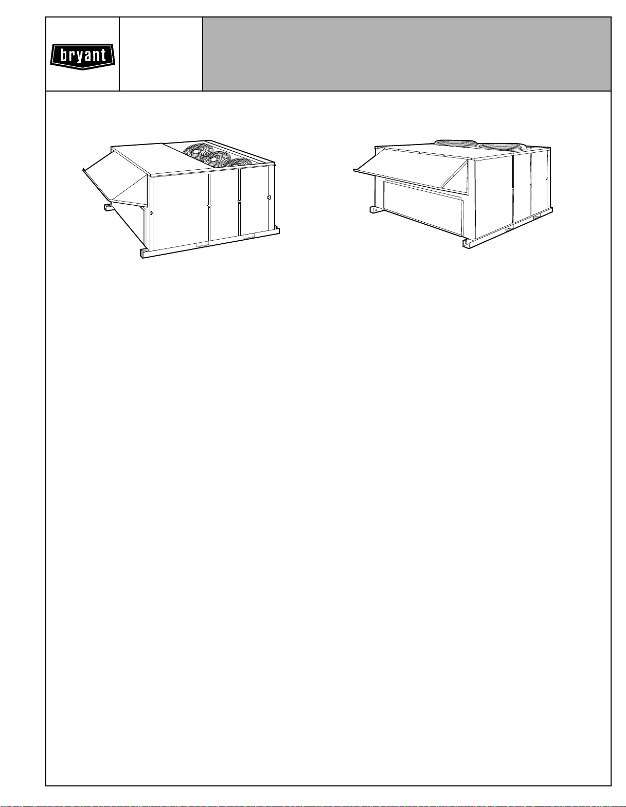
Model 581A
Sizes 155-240
13 to 20 Tons
Model 581A155,180
DESCRIPTION
The 581A gas heating/electric cooling rooftop units are designed to deliver optimum performance and reliability in a commercial rooftop unit.
The 13 to 20 ton units are one-piece gas heating, electric cooling units that are prewired and precharged with R-22 at the factory, making jobsite installation easy. Every unit is factory runtested prior to shipment to ensure reliable installation.
The 581A units are designed to be field-convertible from vertical
supply/return to horizontal supply/return (using an accessory
horizontal supply curb or adapter), making them easily adaptable to a wide variety of new construction and replacement applications. For vertical supply/return jobs, ductwork can be
connected directly to the roof curb, allowing ductwork to be
completed before unit is available for installation. All units include easily replaceable internal filters.
The 581A units are available in a range of heating sizes and
voltage options to meet most job requirements. Low-voltage terminal blocks make wiring connections quick and simple.
All units are listed with ETL (ETL Testing Laboratory) and ETLC
(ETL Testing Laboratory for Canadian certification). All units are
ARI (Air-Conditioning & Refrigeration Institute) approved and
comply with ASHRAE Standard 62 (American Society of Heating, Refrigeration, and Air Conditioning Engineers).
STANDARD FEATURES
INDUSTRY-LEADING COOLING EERS (Energy Efficiency Ra-
tios) assure minimum operating costs and will qualify for attractive utility rebates in many areas.
SEMI-HERMETIC COMPRESSORS are fully serviceable. They
are highly regarded and preferred by owners and users, and are
offered exclusively on the high-efficiency 13 to 20 ton 581A
units.
Two 06D semi-hermetic compressors on independent refrigeration circuits are offered on the 180 and 240 units for 2 steps of
capacity control and redundancy. A single 06D semi-hermetic
compressor with unloading capability is offered on the 155 units.
All compressors have service valves and a full complement of
Model 581A240
safety devices, including high- and low-pressure switches, overtemperature protection, an electronic compressor lockout device, and crankcase heaters.
HIGH STATIC OVERSIZED FAN MOTORS AND VARIABLEPITCH BELT DRIVES are supplied standard from the factory to
provide up to 2 in. wg of external static pressure at 400 cfm per
ton with wet coils and clean filters installed. A 5 hp motor is provided standard on the 581A180 (15-ton unit), and a 10 hp motor
is standard on the 581A240 (20-ton unit).
EASY INSTALLATION makes these units perfect for vertical
supply and return roof curb mount applications on new construction, retrofit, and replacement applications. The unique
industry-leading compact size and weight are favored by designers, contractors, owners, and users, and are significant advantages in terms of minimizing required roof structures on new
construction and retrofit jobs.
The new 581Aunitscanbeeasily converted to horizontal supply
and return with the new fan-performance-boosting horizontal
high-static regain adapter (part no. 389210-201 or 389211-201).
These vertical-to-horizontal supply/return adapters are not only
fully factory assembled with a built-in insulated transition duct,
they improve fan performance by as much as 0.6 in. wg of
static.
THE FACTORY-ASSEMBLED PACKAGE is a compact, fully
self-contained electric cooling/gas heating unit that is prewired,
prepiped, and precharged for minimum installation expense.
INTERNAL RETURN-AIR FILTERS are provided. Two-in.
throwaway filters are provided standard on all units, and can be
easily accessed. There is no need to field-fabricate filter racks
or install external filter accessories.
COMPRESSOR PROTECTION is assured. The 581A units
have high- and low-pressure protection external to the compressor. These protections prohibit operation under abnormal unit
conditions.
DUAL COMPRESSORS AND DUAL REFRIGERATION CIRCUITS (180,240 units) are provided. Two compressors, each
on its own independent circuit, provide standby reliability and
high operating efficiency.
POWER, CONTROL, AND GAS CONNECTIONS are made on
the same side of the unit to simplify installation.
Form No. PDS 581A.155.2B
Page 2

INDUCED-DRAFT COMBUSTION provides the exact amount
of combustion air for the most efficient operation. Induced-draft
combustion also eliminates the flue stack, giving the unit a low
profile appearance. The draw-through design ensures safe operation under any conditions.
INTERMITTENT SPARK IGNITION eliminates the standing pilot flame that consumes gas when the furnace is shut down. The
pilot is ignited only when the thermostat calls for heat.
TUBULAR U-SHAPED CELL design of the heat exchanger
provides high-efficiency heating operation. The hot gases make
2 passes over the supply-air path to enhance efficiency.
POSITIVE-PRESSURE MECHANICAL FLUE GAS VENTING
is unaffected by adverse wind conditions.
FURNACE SAFETY CONTROLS shut off gas if there is a pilot
outage, combustion-air failure, overheating of heat exchangers,
or flame rollout.
TWO-STAGE HEATING WITH 2 INDEPENDENT GAS CONTROL SYSTEMS (180,240 units) minimizes heating costs.
These independent gas control systems make single-stage
heating possible if one stage fails.
ADVANCED DESIGN of evaporator and condenser coils provides optimum heat transfer and cooling efficiency. Coils are
computer-designed with advanced heat transfer surfaces, and
are fabricated of copper tubing with aluminum fins.
COMMERCIAL STRENGTH BASE RAILS with built-in rigging
capability allow easy rigging of unit.
WEATHER-RESISTANT CABINET is built for durability in any
climate. The cabinet is made of pre-painted, galvanized steel for
long life and high-quality appearance.
LOW-AMBIENT OPERATION is provided standard. The units
operate in cooling down to 35 F as shipped from the factory.
Low-ambient kits are not required for most applications.
COMPRESSOR VIBRATION ISOLATION MOUNTING on all
units eliminates noise-causing vibration transmission into the
conditioned space.
CRANKCASE HEATERS keep the oil free of refrigerant during
the off cycle for added compressor life and reliability.
STANDARD WARRANTIES include 1 year on parts (no labor),
with an additional 4 years on compressors (155 units) and
heat exchangers (all units). Additional extended warranties are
available.
BELT-DRIVEN EVAPORATOR-FAN MOTORS are standard on
all units and allow adjustment of the available static pressure to
meet the job requirements of even the most demanding
applications.
Manual Outdoor-Air Dampers — Package consists of a
damper which can be set at 25% outdoor air. The package includes a rainhood and birdscreen.
SUGGESTED USE
• To allow a fixed percentage of outdoor air for ventilation under
all conditions.
• The damper may be used on either vertical or horizontal
applications.
NOTE: The 25% manual outdoor-air damper will be factory
installed whenever the factory-installed economizer is not
chosen.
FIELD-INSTALLED ACCESSORY
DESCRIPTION AND USAGE
Roof Curbs (Horizontal and Vertical) — Full-perimeter galva-
nized steel support frame in 14- and 24-in. high designs provides wood nailer to attach roof counter flashing. Insulated
basepans in curb are provided to prevent condensation. Ductwork attaches to rails provided in the roof curb. A gasket is provided to form an air- and watertight seal between unit and curb.
The gasket meets the standards of the NRCA (National Roofing
Contractors’ Association).
SUGGESTED USE:
• Rooftop application for vertical or horizontal discharge.
• Slab-mounted applications when elevation of the unit is
necessary.
Horizontal Adapter — The adapter is prefabricated, factoryassembled with built-in insulated duct, and permits full perimeter mounting.
SUGGESTED USE:
• Rooftop applications for horizontal discharge where high air
delivery cfms are required.
Two-Position Damper — Package consists of a low-leak
damper assembly for easy installation. The damper will allow either 0 or 25% outdoor air into the unit any time the evaporator
fan is running. When the evaporator fan is off or when there is a
loss of power, the damper will be closed.
SUGGESTED USE:
• Allows a fixed percentage of outdoor air any time the evaporator fan is on, but closes when the evaporator fan is off to
prevent cold backdrafts and wasted energy.
• The damper may be used on either vertical or horizontal airflow applications.
Economizer — See description listed under Factory-Installed
Options Description and Usage section above.
FACTORY-INSTALLED OPTIONS DESCRIPTION
AND USAGE
Economizer — The economizer will allow a fixed percentage
(between 0 and 100%) outdoor ventilation air into the unit any
time the evaporator fan is running. A dry-bulb thermostat placed
outdoors will bring in 100% outdoor air whenever the temperature of the outdoor air alone will adequately provide cooling. If
the economizer alone cannot provide enough cooling, then simultaneous economizer and compressor operation will provide
the most economical operation.
SUGGESTED USE:
• To allow a fixed percentage of outdoor air any time the evaporator fan is on, or operates in economizer mode if outdoor air
can provide cooling, but closes when the evaporator fan is off
to prevent cold backdrafts and wasted energy.
• To reduce energy usage. Use whenever the number of hours
of operation at below 55 F is significant.
• The damper may be used on either vertical or horizontal
applications.
CONTENTS
Page
Model Description .................................3
Heating Capacities and Efficiencies ...................4
Capacity Ratings ..................................4
Dimensional Drawings ............................5-8
Specifications ...................................9,10
Selection Procedure ..............................11
Gross Cooling Capacities ........................12-14
Air Delivery ....................................15-17
Electrical Data ...................................19
Operating Sequence ..............................20
Typical Wiring Schematic .........................20,21
Typical Installation ................................22
Application Data ................................23,24
Engineers’ Specification Guide ......................25
2
Page 3
FIELD-INSTALLED ACCESSORY DESCRIPTION AND USAGE (cont)
Thermostats and Subbases — Provide staged cooling and
heating, automatic (or manual) changeover, fan control, and indicator light.
SUGGESTED USE:
• To control unit operations.
Enthalpy Control Sensor — Package consists of a solid-state
sensor to be paired with a second enthalpy sensor for differential enthalpy control. This sensor is mounted on the economizer
assembly so that it can sense building return-air temperature.
The 2 sensors will determine which combination of outdoor and
return air will provide the greatest energy savings.
SUGGESTED USE:
• To enhance economizer operation for maximum energy
savings.
NOTE: A single sensor may be used for single-sensor, outdoorair, enthalpy control if desired.
Time GuardT II Device — Package consists of a control to be
field wired into the unit controls, and provides a 5-minute delay
in compressor operation between cooling cycles.
SUGGESTED USE:
• Prevents compressor short cycling when rapid compressor
cycles may be a problem.
Head Pressure Control Device — Kit consists of an outdoorair thermostat that permits adequate head pressure control during cooling operation at low outdoor-ambient temperatures.
Refer to Trade Prices for more details or contact your local
representative.
SUGGESTED USE:
• When cooling at low-ambient outdoor temperatures is
desired.
Low-Ambient Kit — Kit consists of a solid-state control and
condenser coil temperature sensor to modulate the condenserfan motors in order to maintain condenser-coil head pressure
for proper cooling operation. Refer to Trade Prices for more details or contact your local representative.
SUGGESTED USE:
• Whenever cooling is required at low outdoor ambient temperatures (as low as –20 F).
• Low-ambient kit is not usually required when economizer is
used.
Barometric Relief Package — This package is useful when it
is necessary to remove excess pressure from the conditioned
space.
NOTE: Optional economizer is required.
SUGGESTED USE:
• When the job requires the ability to relieve internal building
pressure.
Power Exhaust Package — This package is useful when it is
necessary to remove excess pressure from the conditioned
space.
NOTE: Optional economizer is required.
SUGGESTED USE:
• When the job requires the ability to relieve internal building
pressure and pressure losses through the return-air ductwork
are greater than 0.20 in. wg.
• When the job requires the ability to move large quantities of
air to relieve pressure in the conditioned space.
Winter Start Time Delay Relay — Used in conjunction with accessory low-ambient kit or head pressure control device, permits operation in cooling at lower outdoor ambient temperatures. See Trade Prices for more details or contact your local
representative.
SUGGESTED USE:
• When job requires the ability to operate in cooling at low
outdoor-ambient temperatures.
LEGEND
ODS — Order Distribution System
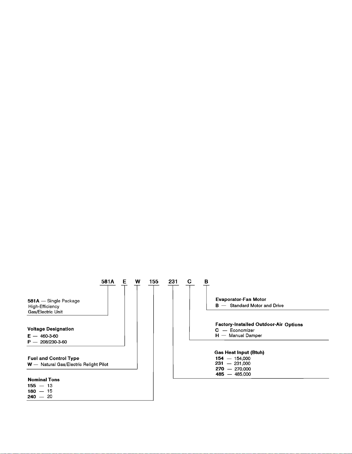
MODEL DESCRIPTION
(ODS Model Number)
3
Page 4
HEATING CAPACITIES AND EFFICIENCIES
UNIT 581A
155 154 —/154,000 123,000 15-45 80 2485
155 231 231,000/115,500 185,000 25-55 80 3057
180 270 270,000/115,500 216,000 15-45 80 4364
240 270 270,000/115,500 216,000 15-45 80 4364
240 485 485,000/242,500 388,000 35-65 80 5427
HEATING INPUT
(Btuh)
Stage 2/Stage 1
OUTPUT CAPACITY
(Btuh)
TEMPERATURE
RISE (F)
STEADY-STATE
EFFICIENCY
(%)
MINIMUM
HEATING
CFM
CAPACITY RATINGS
UNIT 581A
155 13 146,000 13.91 10.5 12.8
180 15 186,000 18.05 10.3 10.5
240 20 234,000 25.29 9.3 9.3
ARI — Air Conditioning and Refrigeration Institute
EER — Energy Efficiency Ratio
IPLV — Integrated Part-Load Values
NOTE:
Rated in accordance with ARI Standards 360-86.
Ratings are net values, reflecting the effects of circulating fan heat.
Ratings are based on:
NOMINAL
TONS
LEGEND
NET COOLING
(Btuh)
TOTAL
kW
EER IPLVCAPACITY
Cooling Standard: 80 F db, 67 F wb indoor entering-air temperature and 95 F db air entering out-
door unit.
IPLV Standard: 80 F db, 67 F wb indoor entering-air temperature and 80 F db outdoor entering-air
temperature.
4
Page 5
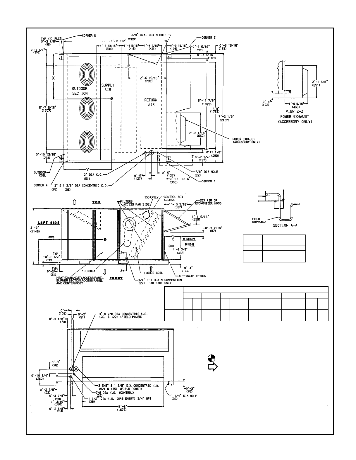
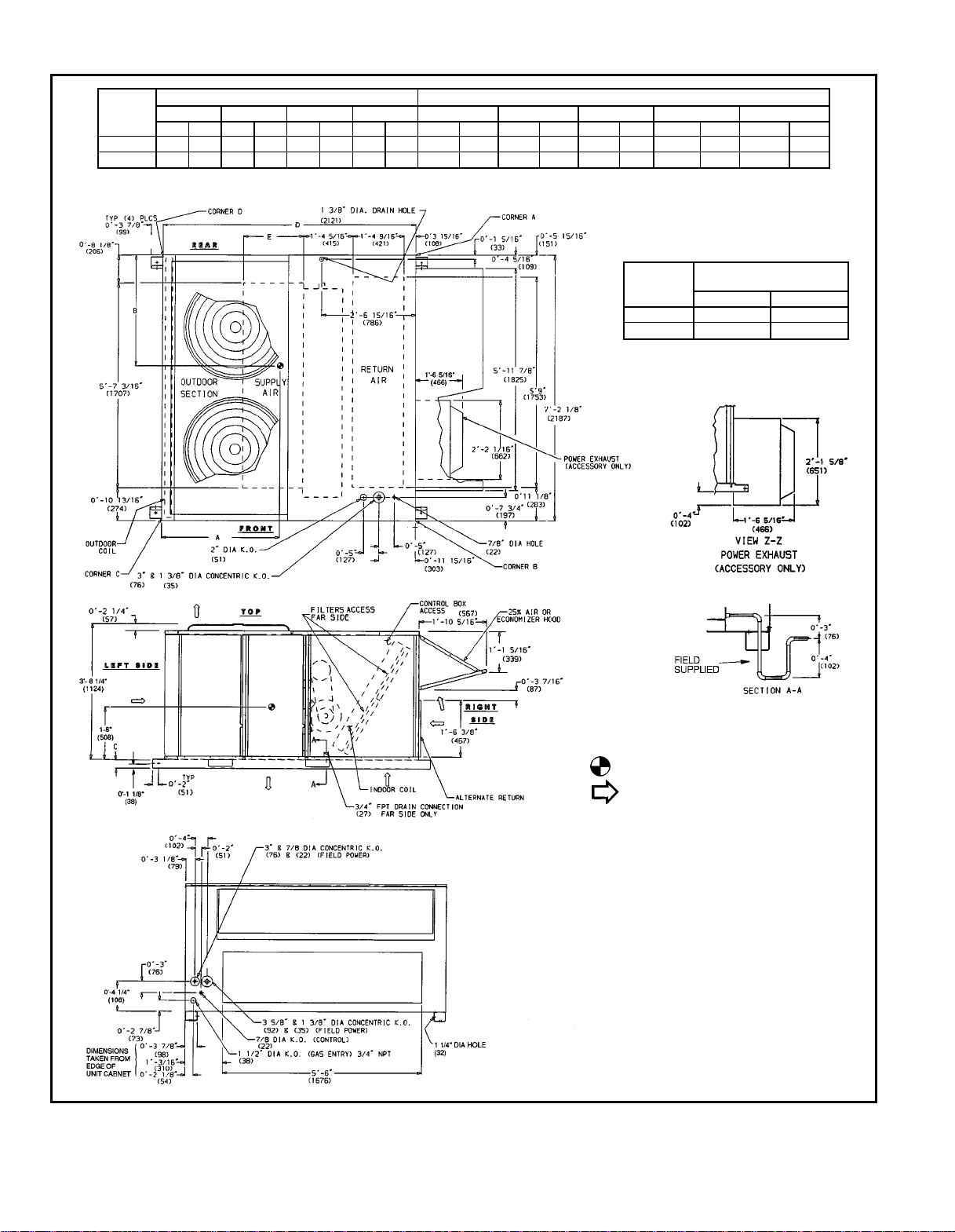
DIMENSIONAL DRAWING — 581A155,180
UNIT
MAXIMUM SHIPPING
581A
WEIGHT
155 154 1920 871
155 231 1940 880
180 270 2310 1048
UNIT
581A
WEIGHT OF CORNER* DIMENSIONS
ABCD X Y Z
Lb Kg Lb Kg Lb Kg Lb Kg Ft-in. mm Ft-in. mm Ft-in. mm
155 154 365 166 360 163 373 169 540 245 3-2 965 3-1
155 231 372 169 363 165 377 171 547 248 3-2 965 3-1
180 270 509 231 506 230 475 216 519 235 3-7
3
⁄81102 3-43⁄81035 1- 8 508
*Weights are for unit only and do not include options or crating.
NOTES:
1. Dimensions in ( ) are in millimeters.
2. Center of gravity.
3. Direction of airflow.
4. Ductwork to be attached to accessory roof curb only.
5. Minimum clearance:
a. Rear: 78-09 (2134) for coil removal. This dimension can be reduced to
48-09 (1219) if conditions permit coil removal from the top.
b. Left side: 48-09 (1219) for proper condenser coil airflow.
c. Front: 48-09 (1219) for control box access.
d. Rightside: 48-09 (1219) for proper operation of damper and power ex-
haust (if so equipped).
e. Top: 68-09 (1829) to assure proper condenser fan operation.
f. Local codes or jurisdiction may prevail.
6. With the exception of clearance for the condenser coil and the damper/
power exhaust as stated in Note No. 5, a removable fence or barricade
requires no clearance.
7. Dimensions are from outside of corner post. Allow 08side for top cover drip edge.
3
⁄8949 1-10 559
1
⁄4946 1-10 559
5
⁄169 (8) on each
5
Page 6
DIMENSIONAL DRAWING — 581A240
UNIT
581A
ABCD A B C D E
Lb Kg Lb Kg Lb Kg Lb Kg Ft-in. mm Ft-in. mm Ft-in. mm Ft-in. mm Ft-in. mm
240 270 523 237 541 245 574 260 596 270 3-4 1016 3-7 1092 0-3 76 6-11
240 485 465 211 486 220 725 329 737 334 4-2 1270 3-5 1041 0-4
CORNER WEIGHT* DIMENSIONS
1
⁄2114 8- 71⁄42623 3-35⁄81006
*Weights are for unit only and do not include options or crating.
UNIT
581A
240 270 2514 1140
240 485 2793 1267
1
⁄22121 1-713⁄16504
MAXIMUM SHIPPING
WEIGHT
Lb Kg
NOTES:
1. Dimensions in ( ) are in millimeters.
2. Center of gravity.
3. Direction of airflow.
4. Ductwork to be attached to accessory roof curb only.
5. Minimum clearance:
a. Rear: 7809 (2134) for coil removal. This dimension
can be reduced to 4809 (1219) if conditions permit
coil removal from the top.
b. 4809 (1219) to combustible surfaces, all four sides
(includes between units).
c. Left side: 4809 (1219) for proper condenser coil
airflow.
d. Front: 4809 (1219) for control box access.
e. Right side: 4809 (1219) for proper operation of
damper and power exhaust (if so equipped).
f. Top: 6809 (1829) to assure proper condenser fan
operation.
g. Bottom: 149 (356) to combustible surfaces (whennot
using curb).
h. Control box side: 3809 (914) to ungrounded surfaces
(non-combustible).
i. Control box side: 3869 (1067) to block or concrete
walls, or other grounded surfaces.
j. Local codes or jurisdiction may prevail.
6. With the exception of clearance for the condenser coil
and the damper/power exhaust as stated in Note No. 5,
a removable fence or barricade requires no clearance.
7. Dimensions are from outside of corner post. Allow
5
⁄169 (8) on each side for top cover drip edge.
08-
6
Page 7
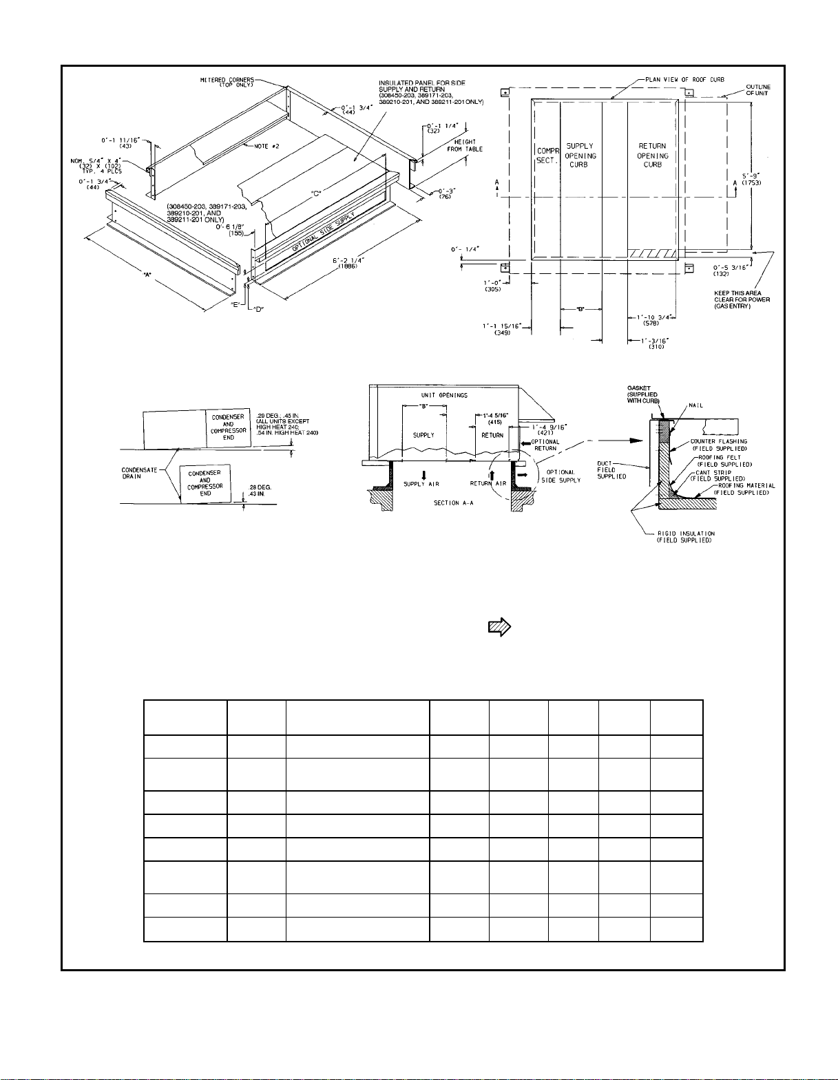
DIMENSIONAL DRAWING — HORIZONTAL AND VERTICAL ROOF CURBS AND HORIZONTAL ADAPTER
NOTE: To prevent the hazard of stagnant water build-up in the drain pan
of the indoor-air section, unit can only be pitched as shown.
ACCESSORY
PACKAGE
NO.
308450-201
308450-202
308450-203
389210-201
389171-201*
389171-202*
389171-203*
389211-201*
CURB
HEIGHT
18-29 Standard Curb — 58-7
(355) 149 High (1703) (503)
28-09
(610)
28-09
(610)
18-119
(584)
18-29 Standard Curb — 78-2
(355) 149 High (2205) (1006)
28-09
(610)
28-09
(610)
18-119
(584)
DESCRIPTION ‘‘A’’ ‘‘B’’ ‘‘C’’ ‘‘D’’ ‘‘E’’
Standard Curb for
High Installation
Horizontal Supply and 58-7
Pre-Assembled, High-Static,
Horizontal Adapter
Standard Curb
High Installation
Horizontal Supply 78-2
Pre-Assembled, High-Static,
Horizontal Adapter
*For 581A240 high-heat applications.
COMPR SECT. — Compressor Section
LEGEND
NOTES:
1. Roof curb accessory is shipped unassembled.
2. Insulated panels,
3. Dimensions in ( ) are in millimeters.
1
⁄2-in. thick neoprene-coated, 2 lb density.
4. Direction of airflow.
5. Roof curb: 18 gage steel.
6. Attach all ductwork to roof curb.
7. Field installation of sidewall insulation is mandatory.
1
⁄169 18-713⁄
1
⁄
16
58-7
(1703)
1
⁄
16
(1703)
1
⁄
16
58-7
(1703)
13
⁄169 38-35⁄
13
⁄
16
78-2
(2205)
13
⁄
16
(2205)
13
⁄
16
78-2
(2205)
9
9
9
9
9
9
18-713⁄
(503)
18-713⁄
(503)
18-713⁄
(503)
38-35⁄
(1006)
38-35⁄
(1006)
38-35⁄
(1006)
16
9
———
16
9
———Units Requiring
16
9
58-69
(1676)
16
9
68-29
(1880)
8
9
8
9
8
9
58-69
(1676)
8
9
68-29
(1880)
08-21⁄
2
(64)
08-61⁄
4
(159)
———
———for Units Requiring
08-21⁄
2
(64)
08-61⁄
4
(159)
9
18-69
(457)Return Curb
9
18-25⁄
8
9
(371)
9
18-69
(457)and Return Curb
9
18-25⁄
8
9
(371)
7
Page 8
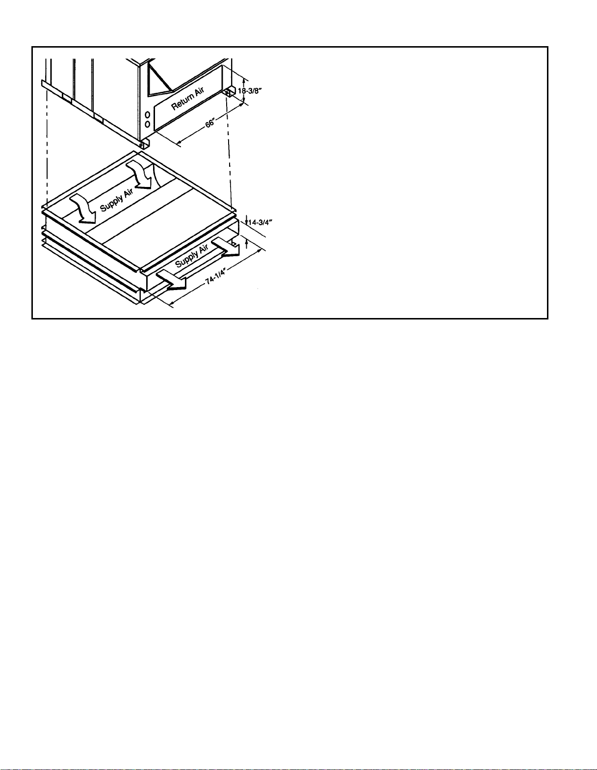
DIMENSIONAL DRAWING — HORIZONTAL ADAPTER INSTALLATION
NOTES:
1. The 389210-201 and 389211-201 are fully factory-preassembled horizontal adapters which include an insulated high-static regain transition
duct to substantially improve fan static performance.
2. Power exhaust and barometric relief accessories cannot be used with
factory pre-assembled, high-static, horizontal adapters.
8
Page 9

SPECIFICATIONS
UNIT SIZE 155 180 240
NOMINAL CAPACITY (tons) 13 15 20
OPERATING WEIGHT (lb)
Unit
Al/Al* 1640/1660† 2010 2235/2413†
Al/Cu* 1770/1790† 2160 2385/2563†
Cu/Cu* 1840/1860† 2250 2515/2693†
Economizer 110 110 110
Roof Curb** 200 200 200/213
COMPRESSOR Semi-Hermetic
Quantity 12 2
Cylinders 64 6
REFRIGERANT TYPE R-22
Quantity (lb)
System 1 22.50 14.25 17.50
System 2 — 15.00 17.00
CONDENSER COIL Enhanced Copper Tubes, Aluminum Lanced Fins
Rows...Fins/in. 3...15 4...15 4...15
Total Face Area (sq ft) 22.2 22.2 22.2
CONDENSER FAN Propeller Type
Nominal Cfm 10,500 14,200
Quantity...Diameter (in.) 3...22 2...30
Motor Hp...Rpm
Watts Input (Total) 1090 3550
EVAPORATOR COIL Copper Tubes, Aluminum or Copper Plate Fins
Rows...Fins/in. 2...17 3...15 4...15
Total Face Area (sq ft) 17.9 17.9 17.9
EVAPORATOR FAN Centrifugal Type
Quantity...Size (in.) 2...10 x 10 2...12 x 12 2...12 x 12
Type Drive Belt Belt Belt
Nominal Cfm 5000 6000 8000
Motor Hp 3.7 5 10
Maximum Continuous Bhp 4.25 5.90
Motor Frame Size 56H 184T 215T
Fan Rpm Range 1194-1526 1238-1494 1323-1579
Motor Bearing Type Ball Ball Ball
Maximum Allowable Rpm 1550 1550 1550
Motor Pulley Pitch Diameter Min/Max (in.) 3.4/4.4 5.4/6.6 5.8/7.0
Nominal Motor Shaft Diameter (in.)
Fan Pulley Pitch Diameter (in.) 5.2 7.9 7.9
Nominal Fan Shaft Diameter (in.) 13⁄
Belt, Quantity...Type...Length (in.) 1...AX...42 1...BX...50 1...BX...51
Pulley Center Line Distance (in.) 13.5-15.5 13.3-14.8 14.6-15.4
Speed Change per Full Turn of
Movable Pulley Flange (rpm)
Movable Pulley Maximum Full Turns
From Closed Position
Factory Setting 3.5 3 3
Factory Speed Setting (rpm) 1293 1366 1451
Fan Shaft Diameter at Pulley (in.) 1
7
⁄
8
16
66 34 43
56 6
3
⁄
16
LEGEND
Al — Aluminum
Bhp — Brake Horsepower
Cu — Copper
*Evaporator coil fin material/condenser coil fin material.
†Low-heat weight/high-heat weight.
**Weight of 14-in. roof curb.
††Rollout switch is manual reset.
NOTE: The 581A units have a low-pressure switch (standard) located
on the suction side.
1
⁄2...1075 1...1075
11⁄
8
17⁄
16
17⁄
16
(Table continued on next page.)
10.2 [208/230 v]
11.8 [460 v]
13⁄
8
17⁄
16
17⁄
16
9
Page 10

SPECIFICATIONS (cont)
UNIT SIZE 155 180 240
FURNACE SECTION Low Heat High Heat High Heat Low Heat High Heat
Rollout Switch Cutout
Temp (F)††
Burner Orifice Diameter
(in. ...drill size)
Natural Gas .113...33 .113...33 .113...33 .113...33 .113...33
Pilot Orifice Diameter
(in. ...drill size)
Natural Gas
Thermostat Heat Anticipator
Setting (amps)
208/230 v Stage 1 0.98 0.98 0.98 0.98 0.98
460 v Stage 1 1.20 1.20 1.20 1.20 1.20
Gas Input (Btuh) Stage 1 154,000 115,500 115,500 115,500 242,500
Efficiency (Steady
State) (%)
Temperature Rise Range 15-45 25-55 15-45 15-45 35-65
Manifold Pressure
(in. wg)
Natural Gas 3.5 3.5 3.5 3.5 3.5
Gas Valve Pressure Range
Psig 0.180-0.487 0.180-0.487 0.180-0.487 0.180-0.487 0.180-0.487
in. wg 5.0-13.5 5.0-13.5 5.0-13.5 5.0-13.5 5.0-13.5
Gas Valve Quantity 22222
Field Gas Connection
Size (in.)
Stage 2 — 0.44 0.44 0.44 0.44
Stage 2 — 0.60 0.60 0.60 0.60
Stage 2 — 231,000 270,000 270,000 485,000
HIGH-PRESSURE SWITCH (psig)
Standard Compressor
Internal Relief
Cutout 426
Reset (Auto.) 320
LOW-PRESSURE SWITCH (psig)
Cutout 7
Reset (Auto.) 22
FREEZE PROTECTION
THERMOSTAT (F)
Opens 30±5
Closes 45±5
OUTDOOR-AIR INLET SCREENS Cleanable
Quantity...Size (in.) 2...20 x 25 x 1
RETURN-AIR FILTERS Throwaway
Quantity...Size (in.) 4...20 x 20 x 2
190 190 190 190 190
0.55...54
.055...54,
.041...59
.055...54,
.041..59
.055...54,
.041...59
80 80 80 80 80
3
⁄
4
3
⁄
4
3
⁄
4
3
⁄
4
—
1...20 x 20 x 1
4...16 x 20 x 2
.071...50,
.071...50
3
⁄
4
LEGEND
Al — Aluminum
Bhp — Brake Horsepower
*Evaporator coil fin material/condenser coil fin material.
†Low-heat weight/high-heat weight.
**Weight of 14-in. roof curb.
††Rollout switch is manual reset.
NOTE: The 581A units have a low-pressure switch (standard) located
on the suction side.
10
Page 11

SELECTION PROCEDURE (with 581A240 270 example)
I DETERMINE COOLING AND HEATING REQUIRE-
MENTS AT DESIGN CONDITIONS:
Given:
Total Cooling Capacity Required ........205,000 Btuh
Sensible Heat Capacity ...............162,000 Btuh
Required Heating Capacity .............190,000 Btuh
Condenser Entering Air Temperature ............95F
Evaporator Entering Air Temperature ........80FEdb/
67 F Ewb
Evaporator Air Quantity ...................8000 cfm
External Static Pressure .................1.30 in. wg
Power Supply (V-Ph-Hz) ..................460-3-60
edb — Entering dry bulb
ewb — Entering wet bulb
II DETERMINE UNIT SIZE:
Select unit based on cooling requirements.
Enter Gross Cooling Capacities tables on pages 12-14 at
condenser entering temperature of 95 F,evaporator air entering at 8000 cfm and 80 F db and 67 F wb. The 581A240
270 unit will provide a gross cooling capacity of
254,000 Btuh and a sensible heat capacity of 193,800
Btuh. For evaporator air temperatures other than 80 F, calculate sensible heat capacity correction, using the formula
found in Note 3 following the Gross Cooling Capacities
tables.
NOTE: Unit ratings are gross capacities and do not include
the effect of evaporator-fan motor heat. To calculate net
capacities, see Step V.
III SELECT HEATING CAPACITY OF UNIT TO PROVIDE
DESIGN CONDITION REQUIREMENTS:
In the Heating Capacities table on page 4, note that unit
581A240 270 will provide output capacity of 216,000 Btuh,
which is adequate for the given application.
IV DETERMINE FAN SPEED AND POWER REQUIRE-
MENTS AT DESIGN CONDITIONS:
Before entering the Air Delivery tables on pages 15-17,
calculate the total static pressure required based on unit
components. From the given and the Pressure Drop table
on page 18, find:
External static pressure 1.30 in. wg
Economizer 0.10 in. wg
Total Static Pressure 1.40 in. wg
Enter the Air Delivery table for standard 581A240 270
460-v unit at 8000 cfm and 1.40 in. wg external static pressure. Find that the rpm is 1409 and the bhp is 6.84. The
factory-installed standard motor will suffice.
V DETERMINE NET COOLING CAPACITY:
Cooling capacities are gross capacities and do not include
indoor (evaporator) fan motor (IFM) heat. Use the watts input power to the motor from the Air Delivery table.
IFM Watts = 6297
Determine net capacity using the following formula:
Net capacity = gross capacity – IFM heat
= 254,000 Btuh – 6297 Watts (3.412 )
= 254,000 Btuh – 21,485 Btuh
Net capacity = 232,515 Btuh
Net sensible capacity = 193,800 – 21,485 Btuh
Net sensible capacity = 172,315 Btuh
The 581A240 270 is the correct selection for the given
conditions.
Btuh
Watt
11
Page 12

GROSS COOLING CAPACITIES
581A155 (13 TON)
Air Entering
Evaporator
Cfm BF
3750 0.06
4375 0.07
5000 0.08
5625 0.09
6250 0.10
581A155 (13 TON) (cont)
Air Entering
Evaporator
Cfm BF
3750 0.06
4375 0.07
5000 0.08
5625 0.09
6250 0.10
BF — Bypass Factor
Edb — Entering Dry Bulb
Ewb — Entering Wet Bulb
kW — Compressor Motor Power Input
MBtuh — Btuh in thousands
NOTES:
1. Direct interpolation is permissible. Do not extrapolate.
2. The following formulas may be used:
t=t –
ldb edb
t = Wet-bulb temperature corresponding to enthalpy of air
lwb
Ewb
(F)
72 177.0 85.0 9.84 172.0 83.2 10.90 165.0 81.0 12.00
67 164.0 106.0 9.64 157.0 104.0 10.70 150.0 101.0 11.60
62 150.0 126.0 9.42 143.0 123.0 10.40 135.0 119.0 11.30
72 181.0 88.0 9.91 175.0 87.0 11.00 168.0 85.0 12.10
67 167.0 113.0 9.69 161.0 111.0 10.70 154.0 108.0 11.80
62 154.0 136.0 9.51 147.0 132.0 10.50 139.0 129.0 11.40
72 184.0 92.2 10.00 177.0 89.8 11.00 170.0 89.4 12.10
67 169.0 123.0 9.74 165.0 118.0 10.80 157.0 115.0 11.80
62 157.0 145.0 9.56 150.0 142.0 10.50 142.0 139.0 11.60
72 185.0 94.3 10.00 180.0 95.5 11.10 172.0 93.2 12.20
67 172.0 125.0 9.81 166.0 125.0 10.90 159.0 122.0 11.90
62 160.0 152.0 9.63 153.0 150.0 10.60 146.0 146.0 11.60
72 186.0 96.1 10.00 180.0 97.4 11.10 175.0 97.0 12.30
67 173.0 134.0 9.84 167.0 133.0 10.90 160.0 128.0 12.00
62 162.0 159.0 9.66 155. 0 155.0 10.70 149.0 149.0 11.70
Ewb
(F)
72 158.0 78.4 13.00 149.0 75.5 14.00 141.0 72.8 15.10
67 143.0 98.2 12.70 134.0 94.8 13.60 123.0 90.6 14.60
62 126.0 115.0 12.20 113.0 109.0 13.20 102.0 102.0 14.20
72 160.0 82.2 13.10 153.0 79.7 14.20 144.0 77.3 15.20
67 146.0 106.0 12.80 138.0 103.0 13.80 127.0 98.3 14.70
62 129.0 125.0 12.40 119.0 119.0 13.30 109.0 109.0 14.40
72 164.0 86.9 13.20 155.0 83.9 14.20 146.0 81.2 15.30
67 149.0 113.0 12.90 140.0 110.0 13.80 131.0 106.0 14.80
62 134.0 134.0 12.50 125.0 125.0 13.50 116.0 116.0 14.60
72 164.0 90.9 13.30 155.0 87.9 14.20 148.0 85.6 15.40
67 151.0 120.0 13.00 142.0 116.0 13.90 133.0 113.0 14.90
62 140.0 139.0 12.70 132.0 132.0 13.70 122.0 122.0 14.70
72 165.0 94.0 13.30 157.0 91.9 14.30 148.0 88.8 15.30
67 152.0 125.0 13.00 143.0 121.0 13.90 134.0 118.0 14.90
62 143.0 143.0 12.80 136.0 136.0 13.80 129.0 129.0 14.80
LEGEND
sensible capacity (1000 x MBtuh)
leaving evaporator coil (h )
Capacity MBtuh
Total Sensible Total Sensible Total Sensible
Capacity MBtuh
Total Sensible Total Sensible Total Sensible
1.10 x cfm
75 85 95
Compressor
kW
105 115 125
Compressor
kW
lwb
Air Entering Condenser (F)
Capacity MBtuh
Air Entering Condenser (F)
Capacity MBtuh
h=h –
lwb ewb
Where: h
3. The sensible heat capacity is based on 80 F entering dry-bulb (edb)
temperature of air entering evaporator coil.
Below 80 F edb, subtract (corr factor x cfm) from the sensible heat
capacity.
Above 80 F edb, add (corr factor x cfm) to the sensible heat
capacity.
Correction Factor = 1.10 x (1 – BF) x (edb – 80).
Compressor
kW
Compressor
kW
total capacity (1000 x MBtuh)
= Enthalpy of air entering evaporator coil.
ewb
Capacity MBtuh
Capacity MBtuh
4.5 x cfm
Compressor
kW
Compressor
kW
12
Page 13

GROSS COOLING CAPACITIES (cont)
581A180 (15 TON)
Air Entering
Evaporator
Cfm BF
4500 0.03
5250 0.03
6000 0.04
6750 0.05
7500 0.05
581A180 (15 TON) (cont)
Air Entering
Evaporator
Cfm BF
4500 0.03
5250 0.03
6000 0.04
6750 0.05
7500 0.05
BF — Bypass Factor
Edb — Entering Dry Bulb
Ewb — Entering Wet Bulb
kW — Compressor Motor Power Input
MBtuh — Btuh in thousands
NOTES:
1. Direct interpolation is permissible. Do not extrapolate.
2. The following formulas may be used:
t=t –
ldb edb
t = Wet-bulb temperature corresponding to enthalpy of air
lwb
Ewb
(F)
72 224.0 108.0 12.94 216.0 105.0 14.34 206.0 101.2 15.64
67 206.0 133.2 12.62 196.2 129.6 13.94 186.4 125.6 15.16
62 186.2 156.2 12.26 177.0 153.0 13.48 167.6 148.8 14.70
72 230.0 113.2 13.06 220.0 109.4 14.42 210.0 107.0 15.82
67 212.0 143.0 12.74 202.0 139.6 14.08 191.6 135.6 15.34
62 191.8 171.4 12.38 182.6 166.4 13.66 172.6 162.0 14.90
72 234.0 117.8 13.16 224.0 114.8 14.52 214.0 112.4 15.96
67 216.0 152.0 12.84 206.0 148.8 14.20 195.6 144.8 15.46
62 196.4 182.8 12.50 186.8 179.2 13.80 177.0 174.0 15.02
72 236.0 122.8 13.22 226.0 119.6 14.60 216.0 115.8 15.94
67 218.0 160.8 12.92 210.0 157.4 14.28 198.4 153.4 15.56
62 200.0 194.2 12.60 190.6 190.2 13.92 182.6 182.2 15.20
72 238.0 127.8 13.28 228.0 124.0 14.66 216.0 120.4 16.02
67 220.0 168.4 12.96 212.0 165.6 14.34 200.0 161.6 15.62
62 204.0 204.0 12.70 196.2 196.0 14.04 187.6 187.6 15.34
Ewb
(F)
72 194.6 97.4 16.92 183.0 92.6 18.02 171.2 88.6 19.08
67 176.4 121.8 16.38 166.4 117.6 17.48 155.8 113.0 18.42
62 156.8 143.6 15.84 149.0 140.0 16.86 139.4 135.4 17.84
72 198.4 102.0 17.02 186.4 97.6 18.18 172.6 92.2 19.16
67 181.4 131.0 16.54 170.8 127.0 17.66 159.0 121.6 18.60
62 163.0 157.6 16.02 154.0 152.4 17.04 145.4 145.2 18.12
72 200.0 106.8 17.12 188.6 102.6 18.30 176.2 98.0 19.38
67 184.8 140.6 16.70 173.4 136.0 17.80 161.4 129.8 18.74
62 168.2 168.2 16.22 160.0 160.0 17.34 151.4 151.2 18.40
72 202.0 111.8 17.22 190.8 107.6 18.40 178.2 103.0 19.50
67 187.2 149.0 16.80 175.4 144.2 17.88 163.4 138.0 18.90
62 174.0 174.0 16.44 165.4 165.2 17.58 156.2 155.8 18.64
72 204.0 116.4 17.28 192.2 112.4 18.48 178.8 106.8 19.54
67 188.8 157.2 16.86 177.0 151.8 17.98 164.8 145.4 18.98
62 179.0 178.8 16.60 169.6 169.4 17.74 159.6 159.6 18.82
LEGEND
sensible capacity (1000 x MBtuh)
leaving evaporator coil (h )
Capacity MBtuh
Total Sensible Total Sensible Total Sensible
Capacity MBtuh
Total Sensible Total Sensible Total Sensible
1.10 x cfm
75 85 95
Compressor
kW
105 115 125
Compressor
kW
lwb
Air Entering Condenser (F)
Capacity MBtuh
Air Entering Condenser (F)
Capacity MBtuh
h=h –
lwb ewb
Where: h
3. The sensible heat capacity is based on 80 F entering dry-bulb (edb)
temperature of air entering evaporator coil.
Below 80 F edb, subtract (corr factor x cfm) from the sensible heat
capacity.
Above 80 F edb, add (corr factor x cfm) to the sensible heat
capacity.
Correction Factor = 1.10 x (1 – BF) x (edb – 80).
Compressor
kW
Compressor
kW
total capacity (1000 x MBtuh)
= Enthalpy of air entering evaporator coil.
ewb
Capacity MBtuh
Capacity MBtuh
4.5 x cfm
Compressor
kW
Compressor
kW
13
Page 14

GROSS COOLING CAPACITIES (cont)
581A240 (20 TON)
Air Entering
Evaporator
Cfm BF
6000 0.03
7000 0.04
8000 0.05
9000 0.05
10000 0.06
581A240 (20 TON) (cont)
Air Entering
Evaporator
Cfm BF
6000 0.03
7000 0.04
8000 0.05
9000 0.05
10000 0.06
BF — Bypass Factor
Edb — Entering Dry Bulb
Ewb — Entering Wet Bulb
kW — Compressor Motor Power Input
MBtuh — Btuh in thousands
NOTES:
1. Direct interpolation is permissible. Do not extrapolate.
2. The following formulas may be used:
t=t –
ldb edb
t = Wet-bulb temperature corresponding to enthalpy of air
lwb
leaving evaporator coil (h )
Ewb
(F)
72 290.0 142.6 17.12 280.0 139.2 18.78 268.0 135.0 20.40
67 264.0 176.2 16.56 254.0 172.0 18.16 242.0 167.2 19.68
62 242.0 208.0 16.08 228.0 202.0 17.52 214.0 196.0 18.96
72 300.0 151.4 17.36 286.0 147.0 18.98 274.0 142.8 20.60
67 272.0 189.4 16.76 262.0 185.8 18.38 250.0 180.8 19.94
62 250.0 228.0 16.28 236.0 222.0 17.76 222.0 214.0 19.24
72 304.0 159.0 17.46 292.0 154.8 19.12 280.0 150.8 20.80
67 278.0 202.0 16.90 266.0 198.0 18.50 254.0 193.8 20.20
62 256.0 244.0 16.46 244.0 238.0 17.98 230.0 228.0 19.48
72 306.0 166.4 17.52 296.0 162.2 19.26 284.0 158.6 21.00
67 284.0 214.0 17.08 272.0 212.0 18.70 258.0 206.0 20.40
62 260.0 258.0 16.58 250.0 250.0 18.16 240.0 240.0 19.72
72 308.0 176.2 17.54 302.0 170.6 19.42 286.0 165.2 21.00
67 286.0 228.0 17.14 274.0 224.0 18.80 262.0 218.0 20.40
62 266.0 266.0 16.68 258.0 258.0 18.34 246.0 246.0 19.94
Ewb
(F)
72 256.0 130.2 22.00 240.0 125.6 23.60 224.0 119.8 25.00
67 226.0 161.2 21.20 210.0 154.6 22.60 193.8 148.2 24.20
62 199.6 189.0 20.40 185.0 181.2 21.80 170.4 170.4 23.40
72 260.0 139.6 22.20 246.0 133.8 23.80 230.0 128.4 25.40
67 234.0 174.8 21.40 218.0 168.6 23.00 199.2 161.8 24.40
62 208.0 206.0 20.80 194.8 194.6 22.20 181.0 181.0 23.80
72 264.0 146.4 22.40 252.0 141.8 24.00 236.0 136.8 25.60
67 238.0 188.0 21.60 222.0 181.6 23.20 204.0 174.8 24.60
62 218.0 218.0 21.00 206.0 206.0 22.60 192.4 192.4 24.20
72 268.0 154.2 22.60 256.0 149.8 24.20 238.0 144.4 25.80
67 242.0 200.0 21.80 226.0 194.4 23.40 210.0 188.0 24.80
62 228.0 228.0 21.20 214.0 214.0 22.80 200.0 200.0 24.40
72 272.0 161.4 22.60 256.0 157.0 24.20 240.0 152.0 25.80
67 246.0 212.0 22.00 230.0 206.0 23.40 214.0 199.4 24.80
62 236.0 234.0 21.60 222.0 222.0 23.00 208.0 208.0 24.80
LEGEND
sensible capacity (1000 x MBtuh)
Capacity MBtuh
Total Sensible Total Sensible Total Sensible
Capacity MBtuh
Total Sensible Total Sensible Total Sensible
1.10 x cfm
lwb
75 85 95
Compressor
105 115 125
Compressor
kW
kW
Air Entering Condenser (F)
Capacity MBtuh
Air Entering Condenser (F)
Capacity MBtuh
h=h –
lwb ewb
Where: h
3. The sensible heat capacity is based on 80 F entering dry-bulb (edb)
temperature of air entering evaporator coil.
Below 80 F edb, subtract (corr factor x cfm) from the sensible heat
capacity.
Above 80 F edb, add (corr factor x cfm) to the sensible heat
capacity.
Correction Factor = 1.10 x (1 – BF) x (edb – 80).
Compressor
kW
Compressor
kW
total capacity (1000 x MBtuh)
= Enthalpy of air entering evaporator coil.
ewb
Capacity MBtuh
Capacity MBtuh
4.5 x cfm
Compressor
kW
Compressor
kW
14
Page 15

AIR DELIVERY
581A155 (13 TON)
Standard Belt-Drive Motor
Airflow
(Cfm)
Rpm Watts Bhp Rpm Watts Bhp Rpm Watts Bhp Rpm Watts Bhp Rpm Watts Bhp
3750 741 510 0.58 854 715 0.82 952 921 1.05 1041 1130 1.29 1124 1344 1.53
4000 773 647 0.74 882 859 0.98 978 1071 1.22 1064 1285 1.46 1145 1502 1.71
4250 806 796 0.91 912 1015 1.16 1004 1233 1.40 1089 1452 1.65 1167 1674 1.91
4500 839 958 1.09 942 1183 1.35 1032 1407 1.60 1114 1632 1.86 1191 1859 2.12
4750 873 1134 1.29 972 1365 1.56 1060 1595 1.82 1140 1825 2.08 1215 2056 2.34
5000 908 1323 1.51 1003 1560 1.78 1089 1796 2.05 1167 2032 2.32 1241 2268 2.58
5250 942 1527 1.74 1035 1769 2.02 1118 2011 2.29 1195 2252 2.57 1267 2494 2.84
5500 978 1745 1.99 1067 1992 2.27 1148 2240 2.55 1223 2487 2.83 1293 2733 3.11
5750 1013 1978 2.25 1099 2230 2.54 1179 2484 2.83 1252 2736 3.12 1321 2988 3.40
6000 1049 2227 2.54 1132 2483 2.83 1210 2742 3.12 1282 2999 3.42 1349 3257 3.71
6250 1085 2491 2.84 1166 2751 3.13 1241 3015 3.44 1312 3279 3.74 1378 3541 4.03
581A155 (13 TON) (co nt)
Airflow
(Cfm)
Rpm Watts Bhp Rpm Watts Bhp Rpm Watts Bhp Rpm Watts Bhp Rpm Watts Bhp
3750 1203 1562 1.78 1277 1784 2.03 1349 2010 2.29 1417 2240 2.55 1483 2473 2.82
4000 1222 1724 1.96 1294 1950 2.22 1364 2180 2.48 1431 2413 2.75 1495 2650 3.02
4250 1242 1900 2.16 1313 2129 2.43 1381 2362 2.69 1446 2599 2.96 1509 2839 3.23
4500 1264 2089 2.38 1333 2322 2.65 1399 2558 2.91 1463 2799 3.19 1525 3042 3.47
4750 1286 2290 2.61 1354 2528 2.88 1419 2769 3.15 1482 3012 3.43 1542 3259 3.71
5000 1310 2507 2.86 1376 2748 3.13 1440 2992 3.41 1501 3240 3.69 1560 3489 3.98
5250 1335 2737 3.12 1399 2983 3.40 1461 3230 3.68 1522 3481 3.97 ———
5500 1360 2981 3.40 1423 3231 3.68 1484 3483 3.97 1543 3737 4.26 — — —
5750 1386 3241 3.69 1448 3495 3.98 1508 3750 4.27 — — — — — —
6000 1413 3514 4.00 1474 3773 4.30 1532 4032 4.59 — — — — — —
6250 1440 3803 4.33 1500 4066 4.63 1558 4330 4.93 — — — — — —
LEGEND
Bhp — Brake Horsepower Input to Fan
FIOP — Factory-Installed Option
Watts — Input Watts to Motor
NOTES:
1. Boldface indicates standard operating range.
2. Indicates field-supplied motor and drive required.
3. All other numbers indicate field-supplied drive required.
4.
5. Factory shipped motor drive range is 1194 to 1526 rpm. Other rpms
indicates maximum bhp/watts of standard motor and drive.
require a field-supplied drive.
0.2 0.4 0.6 0.8 1.0
1.2 1.4 1.6 1.8 2.0
External Static Pressure (in. wg)
Standard Belt-Drive Motor
External Static Pressure (in. wg)
6. Static pressure losses (i.e., economizer) must be added to external
static pressure before entering Air Delivery table. See page 18 for
accessory/FIOP static pressure information.
7. Interpolation is permissible. Do not extrapolate.
8. Maximum continuous bhp is 4.25 and the maximum continuous
watts are 3775. Extensive motor and drive testing on these units ensures that the full horsepower range of the motor can be utilized with
confidence. Using your fan motors up to the wattage ratings shown
will not result in nuisance tripping or premature motor failure. Unit
warranty will not be affected.
15
Page 16

AIR DELIVERY (cont)
581A180 (15 TON)
Standard Belt-Drive Motor
Airflow
(Cfm)
Rpm Watts Bhp Rpm Watts Bhp Rpm Watts Bhp Rpm Watts Bhp Rpm Watts Bhp
4500 630 805 0.9 741 1059 1.2 846 1341 1.5 945 1653 1.9 1039 1993 2.2
4800 659 943 1.1 765 1208 1.4 865 1497 1.7 961 1816 2.0 1052 2163 2.4
5100 688 1094 1.2 789 1371 1.5 885 1668 1.9 977 1993 2.2 1064 2345 2.6
5400 717 1262 1.4 814 1550 1.7 907 1856 2.1 994 2187 2.4 1079 2546 2.8
5700 748 1450 1.6 842 1752 2.0 930 2067 2.3 1015 2406 2.7 1096 2770 3.1
6000 776 1648 1.8 867 1963 2.2 952 2289 2.6 1034 2635 2.9 1112 3004 3.4
6300 804 1861 2.1 892 2190 2.5 975 2526 2.8 1053 2880 3.2 1129 3256 3.6
6600 835 2103 2.4 919 2445 2.7 1000 2793 3.1 1076 3156 3.5 1149 3540 4.0
6900 863 2356 2.6 946 2712 3.0 1024 3072 3.4 1098 3445 3.9 1169 3835 4.3
7200 892 2628 2.9 972 2998 3.4 1049 3371 3.8 1120 3754 4.2 1189 4152 4.6
7500 923 2933 3.3 1001 3318 3.7 1076 3704 4.1 1146 4098 4.6 1213 4506 5.0
581A180 (15 TON) (cont)
Airflow
(Cfm)
Rpm Watts Bhp Rpm Watts Bhp Rpm Watts Bhp Rpm Watts Bhp Rpm Watts Bhp
4500 1128 2355 2.6 1211 2734 3.1 1289 3127 3.5 1363 3531 4.0 1433 3944 4.4
4800 1138 2533 2.8 1219 2921 3.3 1297 3325 3.7 1370 3742 4.2 1440 4170 4.7
5100 1148 2722 3.0 1228 3119 3.5 1305 3532 4.0 1377 3961 4.4 1447 4400 4.9
5400 1160 2928 3.3 1238 3332 3.7 1313 3755 4.2 1385 4192 4.7 1454 4643 5.2
5700 1175 3158 3.5 1251 3569 4.0 1324 3999 4.5 1395 4445 5.0 1462 4906 5.5
6000 1188 3398 3.8 1262 3814 4.3 1334 4250 4.8 1403 4704 5.3 1470 5173 5.8
6300 1203 3654 4.1 1275 4075 4.6 1344 4517 5.1 1412 4976 5.6 1478 5453 6.1
6400 1221 3944 4.4 1290 4370 4.9 1358 4817 5.4 1424 5283 5.9 1489 5765 6.5
6900 1238 4245 4.8 1305 4676 5.2 1371 5128 5.7 1436 5598 6.3 1499 6087 6.8
7200 1256 4569 5.1 1322 5006 5.6 1386 5463 6.1 1449 5938 6.6 1509 6420 7.2
7500 1278 4930 5.5 1341 5373 6.0 1403 5835 6.5 1465 6316 7.1 1515 6733 7.5
LEGEND
Bhp — Brake Horsepower Input to Fan
FIOP — Factory-Installed Option
Watts — Input Watts to Motor
NOTES:
1. Boldface indicates standard operating range.
2. Indicates field-supplied motor and drive required.
3. All other numbers indicate field-supplied drive required.
4.
5. Factory shipped motor drive range is 1194 to 1526 rpm. Other rpms
indicates maximum bhp/watts of standard motor and drive.
require a field-supplied drive.
0.2 0.4 0.6 0.8 1.0
1.2 1.4 1.6 1.8 2.0
External Static Pressure (in. wg)
Standard Belt-Drive Motor
External Static Pressure (in. wg)
6. Static pressure losses (i.e., economizer) must be added to external
static pressure before entering Air Delivery table. See page 18 for
accessory/FIOP static pressure information.
7. Interpolation is permissible. Do not extrapolate.
8. Maximum continuous bhp is 5.9, and the maximum continuous watts
are 5180. Extensive motor and drive testing on these units ensures
that the full horsepower range of the motor can be utilized with confidence. Using your fan motors up to the wattage ratings shown will
not result in nuisance tripping or premature motor failure. Unit warranty will not be affected.
16
Page 17

AIR DELIVERY (cont)
581A240 (20 TON)
Standard Belt-Drive Motor
Airflow
(Cfm)
Rpm Watts Bhp Rpm Watts Bhp Rpm Watts Bhp Rpm Watts Bhp Rpm Watts Bhp
6000 800 1732 1.88 891 2047 2.22 975 2376 2.58 1055 2728 2.96 1133 3104 3.37
6500 853 2134 2.32 939 2471 2.68 1018 2819 3.06 1094 3185 3.46 1167 3573 3.88
7000 907 2596 2.82 989 2957 3.21 1064 3324 3.61 1136 3707 4.02 1205 4107 4.46
7500 962 3123 3.39 1039 3507 3.81 1111 3895 4.23 1179 4295 4.66 1245 4710 5.11
8000 1017 3717 4.04 1091 4126 4.48 1160 4536 4.93 1225 4954 5.38 1287 5386 5.85
8500 1072 4385 4.76 1143 4818 5.23 1209 5250 5.70 1271 5688 6.18 1332 6137 6.66
9000 1128 5129 5.57 1196 5587 6.07 1260 6042 6.56 1323 6501 7.06 1377 6968 7.57
9500 1185 5955 6.47 1250 6437 6.99 1311 6915 7.51 1369 7395 8.03 1424 7881 8.56
10000 1241 6865 7.45 1304 7372 8.00 1363 7873 8.65 1419 8376 9.09 1472 8882 9.64
581A240 (20 TON) (cont)
Airflow
(Cfm)
Rpm Watts Bhp Rpm Watts Bhp Rpm Watts Bhp Rpm Watts Bhp Rpm Watts Bhp
6000 1208 3504 3.80 1282 3926 4.26 1353 4368 4.74 1421 4826 5.24 1488 5299 5.75
6500 1239 3983 4.32 1308 4415 4.79 1376 4866 5.28 1442 5337 5.79 1507 5823 6.32
7000 1273 4529 4.92 1339 4970 5.40 1403 5432 5.90 1467 5911 6.42 1520 6339 6.88
7500 1309 5143 5.58 1372 5597 6.08 1434 6067 6.59 1494 6558 7.12 1548 7014 7.62
8000 1349 5833 6.33 1409 6297 6.84 1467 6779 7.36 1529 7313 7.94 ———
8500 1390 6600 7.17 1447 7077 7.68 1504 7571 8.22 ——————
9000 1433 7446 8.08 1488 7938 8.62 —————————
9500 1478 8378 9.10 ————————————
10000 1524 9396 10.20 ————————————
LEGEND
Bhp — Brake Horsepower Input to Fan
FIOP — Factory-Installed Option
Watts — Input Watts to Motor
NOTES:
1. Boldface indicates standard operating range.
2. All other numbers indicate field-supplied drive required.
3.
4. Factory shipped motor drive range is 1323 to 1579 rpm. Other rpms
indicates maximum bhp/watts of standard motor and drive.
require a field-supplied drive.
0.2 0.4 0.6 0.8 1.0
1.2 1.4 1.6 1.8 2.0
External Static Pressure (in. wg)
Standard Belt-Drive Motor
External Static Pressure (in. wg)
5. Static pressure losses (i.e., economizer) must be added to external
static pressure before entering Air Delivery table. See page 18 for
accessory/FIOP static pressure information.
6. Interpolation is permissible. Do not extrapolate.
7. Maximum continuous bhp is 10.2 for 208/230-v units and 11.8 for
460-v units. The maximum continuous watts are 9510 for the 208/
230-v units and 11,000 for the 460-v unit. Extensive motor and drive
testing on these units ensures that the full horsepower range of the
motor can be utilized with confidence. Using your fan motors up to
the wattage ratings shown will not result in nuisance tripping or premature motor failure. Unit warranty will not be affected.
NOTE: The 389210-201, 389211-201 high static regain
adapter accessories may be used to provide horizontal
supply/return.
Horizontal Supply/Return Fan Performance
With 389210-201 or 389211-201 High Static Regain Adapter
17
NOTE: The 389210-201, 389211-201 horizontal supply/
return adapter accessories improve 581A fan performance by increasing external static pressure by amount
shown above.
Page 18

Fan Performance Using Accessory Power Exhaust
SOUND POWER (Total Unit)
UNIT
581A
155 8.8 87.3 87.1 89.9 86.4 84.0 82.7 79.0 73.9 68.6
180 8.9 88.0 95.7 88.9 87.2 85.2 91.9 79.5 72.7 66.0
240 9.5 94.1 90.6 87.2 89.9 86.2 85.8 81.0 75.6 69.6
Bels — Sound Levels (1 bel = 10 decibels)
NOTE: All values are in dB unless otherwise noted.
SOUND
RATING-BELS
(60 Hz)
A-WEIGHTED
(dB)
63 125 250 500 1000 2000 4000 8000
OCTAVE BANDS
AIR QUANTITY LIMITS
UNIT 581A MINIMUM CFM MAXIMUM CFM
155 3750 6,250
180 4500 7,500
240 6000 10,000
ACCESSORY/FIOP ECONOMIZER STATIC PRESSURE (in. wg)
UNIT
581A
155,180 All
240 All
LEGEND
FIOP — Factory-Installed Option
NOTES:
1. The factory-assembled horizontal adapter substantially improves fan performance. See graph on
page 17.
2. The static pressure must be added to external static pressure. The sum and the evaporator
entering-air cfm should then be used in conjunction with the Air Delivery table to determine blower
rpm, bhp, and watts.
UNIT
VOLTAGE
CFM
3,750 .03
4,000 .03
5,000 .05
6,000 .07
7,500 .10
6,000 .07
7,200 .09
9,000 .11
10,000 .12
ECONOMIZER
PRESSURE DROP
18
Page 19

FAN RPM AT MOTOR PULLEY SETTINGS*
UNIT
581A
0
1
⁄
2
11
1
⁄
2
155 1526 1492 1459 1426 1393 1360 1326 1293 1260 1227 1194 — —
180 1494 1472 1451 1430 1408 1387 1366 1345 1323 1302 1281 1259 1238
240 † † 1536 1515 1493 1472 1451 1430 1408 1387 1366 1344 1323
*Approximate fan rpm shown.
†Do not run this fan at less than 1 turn open, as it will exceed the maximum
allowable rpm of 1550.
MOTOR PULLEY TURNS OPEN
22
1
⁄
2
33
1
⁄
2
44
1
⁄
2
55
1
⁄
2
ELECTRICAL DATA
UNIT
581A
NOMINAL
VOLTAGE
(3 Ph,
60 Hz)
VOLTAGE
RANGE
Min Max RLA LRA RLA LRA Qty
208/230 187 254 39.7 228 — — 3 1.7 3.8 3.7 10.5/10.5 84.5/84.5
155
460 414 508 19.9 114 — — 3 0.8 1.9 3.7 4.8 42.3
208/230 187 254 28.2 160 28.2 160 3 1.7 24.8 5 15.8/15.8 105/91
180
460 414 508 14.1 80 14.1 80 3 0.8 10.8 5 7.9 46
208/230 187 254 35.6 198 35.6 198 2 5.5 24.8 10 28.0/28.0 193/168
240
460 414 508 17.8 99 17.8 99 2 2.8 10.8 10 14.6 84
LEGEND
FLA — Full Load Amps
HACR — Heating, Air Conditioning and Refrigeration
IFM — Indoor (Evaporator) Fan Motor
LRA — Locked Rotor Amps
MCA — Minimum Circuit Amps
MOCP — Maximum Overcurrent Protection
NEC — National Electrical Code
OFM — Outdoor (Condenser) Fan Motor
RLA — Rated Load Amps
*This is the maximum size permissible; smaller fuse size may be used where con-
ditions permit.
COMPRESSOR
No. 1 No. 2
OFM IFM
FLA
LRA
(ea)
Hp FLA LRA FLA LRA FLA MCA MOCP* FLA LRA
(ea)
POWER
EXHAUST
COMBUSTION
FAN MOTOR
POWER SUPPLY
DISCONNECT
— — 0.57 65/65 100/100 64/64 324/324
4.6 18.8 0.57 70/70 100/100 70/70 343/343
— — 0.30 32 50 32 162
2.3 6.0 0.30 34 50 34 168
— — 0.57 84/84 110/100 90/90 499/485
4.6 18.8 0.57 89/89 110/110 95/95 518/504
— — 0.30 42 50 45 238
2.3 6.0 0.30 44 50 47 244
— — 0.57 119/119 150/150 127/127 639/614
4.6 18.8 0.57 124/124 150/150 133/133 657/632
— — 0.30 60 70 65 304
2.3 6.0 0.30 63 80 67 310
NOTES: In compliance with NEC requirements for multimotor and combination
load equipment (refer to NECArticles 430 and 440), the overcurrent protective device for the unit shall be fuse or HACR breaker. The Canadian units may be fuse
or circuit breaker.
6
SIZE
19
Page 20

OPERATING SEQUENCE
COOLING, UNITS WITHOUT ECONOMIZER — When thermo-
stat calls for cooling, terminals G and Y1 are energized. The indoor (evaporator) fan contactor (IFC) and compressor contactor
no. 1 (C1) are energized, and evaporator-fan motor, compressor no. 1 (581A180,240) or unloaded compressor (581A155),
and condenser fan start. The condenser-fan motor runs continuously while unit is cooling. For units with 2 stages of cooling, if
the thermostat calls for a second stage of cooling by energizing
Y2, compressor contactor no. 2 (C2) is energized and compressor no. 2 starts (581A180,240) or compressor no. 1 runs fully
loaded (581A155).
HEATING, UNITS WITHOUT ECONOMIZER
NOTE: The 581A155 (High Heat), 180,240 units have 2 stages
of heat.
Set thermostat system switch at HEAT or AUTO. position and
set fan switch to AUTO. position for heating.
When first-stage thermostat calls for heat, time-delay relay for
evaporator fan begins timer sequence. Induced-draft relay
closes, and induced-draft motor starts.
Pressure switch closes and pilot valve no. 1 opens, allowing gas
to flow to the first-stage pilot. Spark ignitor ignites pilot flame.
Sensor detects flame and the main gas valve no. 1 opens. Gas
flows to main burners and first-stage burners ignite. Spark ignitor turns off.
When sequence is complete, time-delay relay closes and
evaporator fans start.
Second Stage — 581A155 High-Heat and 581A180,240
Units — With an additional heating call, the second-stage ther-
mostat closes. (The control relay closes during the first stage of
operation.) Pilot valve no. 2 opens, and the spark ignitor ignites
pilot. The sensor detects a flame and energizes main gas valve
coil no. 2, opening main gas valve no. 2. Gas flows to the main
burners, and the second stage burners ignite. The spark ignitor
turns off.
When the second-stage thermostat is satisfied, the secondstage gas valve closes.
When the first-stage thermostat is satisfied, the first-stage gas
valve closes. The induced-draft motor turns off, the time relay
opens, and the timer sequence begins. When the sequence is
complete, the evaporator-fan motor turns off.
COOLING, UNITS WITH ECONOMIZER — Upon a call for
cooling, when outdoor ambient is above the enthalpy control
setting, the economizer damper moves to VENT position. The
compressor(s) and evaporator and condenser fans energize.
Upon a first call for cooling, when outdoor ambient is below the
enthalpy control setting, the evaporator fan starts and the
economizer is fully open. The compressor(s) remains off.
Upon a second-stage call for cooling, compressor no. 1 is energized and mechanical cooling is integrated with economizer
cooling. If the outdoor-air temperature drops below 50 F, a cooling lockout switch prevents the compressors from running.
When supply-air temperature drops below a fixed set point, the
economizer damper modulates to maintain the temperature at
the fixed set point.
A freeze protection thermostat (FPT) is located on the evaporator coil. It detects frost build-up and turns off the compressors,
allowing the coil to clear. Once frost has melted, the compressors can be reenergized.
HEATING,UNITS WITH ECONOMIZER — Outdoor-air damper
stays at VENT position while evaporator fan is operating. Refer
to Heating, Units Without Economizer section above for remainder of operating sequence.
LEGEND FOR TYPICAL WIRING SCHEMATIC
BRK W/AT — Breaks with Amp Turns
C—Contactor, Compressor
CLO — Compressor Lockout
COM — Common
CR — Control Relay
CT — Current Transformer
DM — Damper Motor
FPT — Freeze Protection Thermostat
GND — Ground
HPS — High-Pressure Switch
HR — Heat Relay
HV — High Voltage
IP — Ignitor Pilot
ICP — Ignitor Control Pack
IDR — Induced Draft Relay
IFR — Indoor (Evaporator) Fan Relay
LOR — Lockout Relay
LPS — Low-Pressure Switch/Loss of Charge
LS — Limit Switch
MAT — Mixed Air Thermostat
MGV — Main Gas Valve
MV — Main Valve
OAT — Outdoor-Air Thermostat
OFC — Outdoor (Condenser) Fan Contactor
PGV — Pilot Gas Valve
PL — Plug Assembly
PRI — Primary
PV — Pilot Valve
SN — Sensor
TB — Terminal Block
TDR — Time-Delay Relay
TR — Timer Relay
TRAN — Transformer
Terminal (Marked)
Terminal (Unmarked)
Terminal Block
Splice
Splice (Marked)
Factory Wiring
Field Control Wiring
Field Power Wiring
Accessory or Optional Wiring
To indicate common potential only; not to represent wiring.
20
Page 21

TYPICAL WIRING SCHEMATIC (581A240 270 SHOWN)
21
Page 22

TYPICAL INSTALLATION
NEC — National Electrical Code
22
Page 23

APPLICATION DATA
1. Ductwork — Ductwork should be attached to the curb on all
units. Interior installation may proceed before unit is set in
place on roof. If ductwork will be attached to the unit, do not
drill in condensate drain pan area — leaks may result. See
figures on page 24 for information on field-installed concentric ductwork when applicable.
2. Thru-The-Curb Service Connections — Roof curb connections allow field power wires, control wires, and gas supply
to enter through the roof curb opening.
3. Thermostat — Use of 2-stage cooling thermostat is
required.
4. Heating-to-Cooling Changeover — All units are automatic
changeover from heating to cooling when automatic
changeover thermostat and subbase are used.
5. Airflow — Units are draw-thru on cooling and blow-thru on
heating.
6. Maximum Airflow — To minimize the possibility of condensate blow-off from evaporator, airflow through units should
not exceed 500 cfm/ton.
7. Minimum Airflow — The minimum airflow for cooling is
300 cfm/ton.
8. Minimum Ambient Cooling Operation Temperature — Units
are designed to operate at outdoor temperatures down to
35 F. To operate at lower outdoor-air temperatures, see
Trade Prices for appropriate accessories, or contact your
local representative.
9. Maximum Operating Outdoor-Air Temperature — For cooling, this temperature is 120 F (180) or 125 F (155, 240).
10. HighAltitude —A change to the gas orifice may be required
at high altitudes. Refer to Altitude Compensation chart
below.
11. Minimum Temperature— Air entering the heat exchanger in
heating is 50 F continuous and 45 F intermittent.
12. Internal Unit Design — Due to the internal design (drawthru over the motor), air path, and specially designed motors, the full horsepower (maximum continuous bhp) listed
in the Specifications table and the notes following each Air
Delivery table can be utilized with extreme confidence.
Using the motors with the values listed in the Specifications
table
will not
result in nuisance tripping or premature motor
failure. The unit warranty will not be affected.
OPTION AND ACCESSORY LIST
ITEM
Integrated Economizer XX
Manual Outdoor-Air Damper X
Two-Position Damper X
Barometric Relief Damper X
Roof Curbs (Horizontal and Vertical) X
Horizontal Adapter X
Thermostats and Subbases X
Power Exhaust X
Head Pressure Control Device X
Low-Ambient Kit X
Time GuardT II Control Circuit X
Enthalpy Control Sensor X
Winter Start Time-Delay
Relay
FACTORY-
INSTALLED
OPTION
FIELD-
INSTALLED
ACCESSORY
X
ALTITUDE COMPENSATION*
ELEVATION
(Ft)
0-2,000 33
2,000 35
3,000 35
4,000 36
5,000 36
6,000 37
7,000 38
8,000 38
9,000 40
10,000 41
11,000 43
12,000 44
13,000 44
14,000 45
*As the height above sea level increases, there is less oxygen per
cubic ft of air. Therefore, heat input rate should be reduced at higher
altitudes.
†Orifices available through your distributor.
NATURAL GAS
Orifice Size†
ALTITUDE DERATING FACTOR*
ELEVATION
(Ft)
0-2,000 1,100
2,001-3,000 1,050
3,001-4,000 1,000
4,001-5,000 950
5,001-6,000 900
*Derating of the unit is not required unless the heating value of the gas
exceeds the values listed in the table above, or if the elevation exceeds
6000 ft. Derating conditions must be 4% per thousand ft above sea
level. For example, at 4000 ft, if the heating value of the gas exceeds
1000 Btu/ft
6000 ft, the same formula applies. For example, at 7000 ft, the unit will
require a 28% derating of the maximum heating value per the National
Fuel Gas Code.
3
, the unit will require a 16% derating. For elevations above
MAXIMUM HEATING VALUE
(Btu/ft3)
23
Page 24

APPLICATION DATA (cont)
EVAPORATOR-FAN MOTOR PERFORMANCE
UNIT
581A
155
180
240
LEGEND
Bhp — Brake Horsepower
*Extensive motor and electrical testing on these units ensures that the
full horsepower range of the motors can be utilized with confidence.
UNIT
VOLTAGE
208/230
460 4.8
208/230
460 7.9
208/230 10.20 9510 28.0
460 11.80 11,000 14.6
MAXIMUM
ACCEPTABLE
CONTINUOUS
BHP*
4.25 3775
5.90 5180
MAXIMUM
ACCEPTABLE
OPERATING
WATTS
Using your fan motors up to the horsepower ratings shown in this table
will not result in nuisance tripping or premature motor failure. Unit warranty will not be affected.
MAXIMUM
AMP DRAW
10.5
15.8
NOTE: Do not drill in this area; damage to basepan may result in
water leak.
Concentric Duct Air Distribution
NOTE: Dimensions A, A8 and B, B8 are obtained from field-
supplied ceiling diffuser.
Shaded area indicates block-off panels.
Concentric Duct Details
24
Page 25

ENGINEERS’ SPECIFICATION GUIDE
GENERAL: Furnish and install single-package, outdoor rooftopmounted, electrically controlled, heating and cooling unit utilizing reciprocating compressor(s) for cooling and gas combustion
for heating duty. Unit shall discharge supply air vertically or horizontally as shown on the contract drawings.
Nominal unit electrical characteristics shall be
3 ph, 60 Hz. The unit shall be capable of satisfactory operation
within voltage limits of
COOLING CAPACITY: Total cooling capacity of the unit shall be
or greater at conditions of
at unit at
denser entering air of
tions shall be a minimum of
HEATINGCAPACITY: Total heating capacity of the unit shall be
CABINET: The cabinet shall be constructed of galvanized steel,
bonderized and coated with a prepainted, baked enamel finish.
COMPRESSOR: Compressor(s) shall be of the semi-hermetic
type with crankcase heaters and suitable vibration isolators and
dual independent refrigeration circuits shall be supplied
(180,240).
CONDENSER SECTION: The condenser coils shall have aluminum plate fins mechanically bonded to seamless copper
tubes with all joints brazed. Condenser fan shall be of the directdriven propeller type and shall discharge air vertically. Fan shall
have permanently lubricated bearings.
EVAPORATOR SECTION: Evaporator coils shall have aluminum plate fins mechanically bonded to seamless copper tubes
with all joints brazed. Evaporator fan shall be belt driven as
shown on the equipment drawings. Bearings shall be sealed,
permanently lubricated, ball-bearing type.
HEATING SECTION: The unit shall be equipped with an
induced-draft combustion system with energy saving intermittent spark ignition and redundant main gas valve. The heat exchanger shall be of the tubular section type constructed of a
minimum of 20-gage steel coated with a nominal 1.2 mil
aluminum-silicone alloy for corrosion resistance. Burners shall
be of the in-shot type constructed of aluminum coated steel.
Btuh or greater, and sensible capacity shall be Btuh
F dry bulb, F wet bulb and con-
Btuh or greater with a gas input of Btuh.
vto v.
cfm evaporator air entering
F dry bulb. Total design condi-
Btuh/Watt.
REFRIGERANT SYSTEM: Refrigerant system shall include filter drier, fixed orifice feed system, and service gage connections on suction line, liquid line, and compressor discharge line,
as well as low-pressure and high-pressure protection.
FILTER SECTION: Filter section shall consist of factory-
v,
installed low velocity, 2-in. thick fiberglass throwaway filters of
commercially available sizes. Filter access panel shall be easy
access.
CONTROLS: Unit shall be complete with self-contained lowvoltage control circuit. Safeties shall include compressor overtemperature and overcurrent.
Heating section shall be provided with the following minimum
protection: High temperature limit switch, induced-draft pressure switch, manual reset flame rollout switch and flame proving
controls.
OPTIONS: Factory-installed integrated economizer shall include all hardware and controls to provide cooling using outdoor
air alone or in conjunction with mechanical cooling. Dampers
shall be low leakage type, not to exceed 2% leakage at 1.0 in.
wg pressure differential. Economizer shall be capable of introducing up to 100% outdoor air and shall be equipped with a
gravity relief damper. Economizer controls shall be dry-bulb
type.
On all units where the factory-installed economizer is not chosen, the factory-installed manual outdoor-air damper shall be
included.
APPROVALS: The unit shall be ETL, Canada design certified
and ETL tested and certified. All wiring shall be in accordance
with NEC and units shall meet ASHRAE Standard 62. The unit
shall be rated in accordance with ARI Standard 360. Units shall
be designed to conform to NRCA standards. Insulation and adhesive shall meet NFPA90A requirements for flame spread and
smoke generation.
ACCESSORIES: Field-installed accessories shall include: Horizontal and vertical roof curbs (14 in. or 24 in.), horizontal
adapter, economizer, two-position damper, low-ambient kit,
Time GuardT II short-cycle circuit protection, thermostat and
subbase, barometric relief damper, power exhaust, head pressure control device, winter start time-delay relay, and enthalpy
control sensor.
25
Page 26

Bryant
Air Conditioning
SPECIFICATIONS SUBJECT TO CHANGE WITHOUT NOTICE
UNIT MUST BE INSTALLED IN ACCORDANCE
WITH INSTALLATION INSTRUCTIONS
Copyright 1995 Carrier Corporation
Printed in U.S.A. 6/95 CATALOG NO. BY-3258-105
 Loading...