

Page 1

installation, start-up and
service instructions
Dura
SINGLE PACKAGE ROOFTOP
GAS HEATING/ELECTRIC COOLING UNITS
Cancels: II 580F-36-4 II 580F-36-5
580F
Pac
Series
Sizes 036-073
3 to 6 Tons
10/1/05
IMPORTANT — READ BEFORE INSTALLING
1. Read and become familiar with these installation
instructions before installing this unit (Fig. 1A and
1B).
2. Be sure the installation conforms to all applicable local and national codes.
3. These instructions contai n importa nt inform ation for
the proper maintenance and repair of this equipment.
Retain these instructions for futu re use.
CONTENTS
Page
SAFETY CONSIDERATIONS . . . . . . . . . . . . . . . . . . . . . . . . . 1
INSTALLATION . . . . . . . . . . . . . . . . . . . . . . . . . . . . . . . . . .1 -34
I. Step 1 — Provide Unit Support. . . . . . . . . . . . . . . . . 1
II. Step 2 — Field Fabricate Ductwork . . . . . . . . . . . . . 4
III. Step 3 — Install External Trap for
Condensate Drain . . . . . . . . . . . . . . . . . . . . . . . . . . . 4
IV. Step 4 — Rig and Place Unit . . . . . . . . . . . . . . . . . . . 4
V. Step 5 — Install Flue Hood . . . . . . . . . . . . . . . . . . . . 6
VI. Step 6 — Install Gas Piping . . . . . . . . . . . . . . . . . . . 6
VII. Step 7 — Make Electrical Connections . . . . . . . . . 10
VIII. Step 8 — Adjust Factory-Installed Options. . . . . . 14
IX. Step 9 — Adjust Evaporator-Fan Speed . . . . . . . . 22
PRE-START-UP. . . . . . . . . . . . . . . . . . . . . . . . . . . . . . . . . . . 35
START-UP . . . . . . . . . . . . . . . . . . . . . . . . . . . . . . . . . . . . .35-37
SERVICE . . . . . . . . . . . . . . . . . . . . . . . . . . . . . . . . . . . . . .37-43
TROUBLESHOOTING. . . . . . . . . . . . . . . . . . . . . . . . . . . .43-48
INDEX . . . . . . . . . . . . . . . . . . . . . . . . . . . . . . . . . . . . . . . . . . 49
START-UP CHECKLIST . . . . . . . . . . . . . . . . . . . . . . . . . . CL-1
SAFETY CONSIDERATIONS
Installation and servicing of air-conditioning equipment can
be hazardous due to system pressure and electrical components. Only trained and qualified service personnel should
install, repair, or servic e air-conditioning equipment.
Untrained personnel can perform basic maintenance functions of cleaning coils and filters and replacing filters. All
other operations sh o uld be perfor me d by trai ne d se rvi ce personnel. When working on air-conditioning equipment,
observe precautions in the literature, tags and labels
attached to the unit, and other safety precautions that apply.
Follow all safety codes. Wear safety glasses and work gloves.
Use quenching cloth for unbrazing operations. Have fire
extinguishers available for all brazing opera tions.
WARNING: Disconnect gas piping from unit when
leak testing at pressure greater than 1/2 psig. Pressures greater tha n
resulting in hazardous condition. If gas valve is subjected to pressure greater than
replaced before use. When pressure testing fieldsupplied gas piping at pressures of
unit connected to such piping must be isolated by manually closing the gas valve.
WARNING: Before performing service or maintenance operations on unit, turn off main power switch
to unit and install a lockout tag. Electrical shock could
cause personal injury.
CAUTION: Ensure voltage listed on unit data plate
agrees with electrical supply p r ov ided fo r t he unit .
Unit is ship ped in t he ve rti cal d uc t con figu rat ion . To convert t o
horizontal configuration, remove screws from side duct opening covers and remove covers. Using the same screws, install
covers on vertical duct openings with the insulation-side down.
Seals around duct openings must be tight. See Fig. 2.
Confirm before installation of unit that voltage, amperage
and circuit protection requirements listed on unit data plate
agree with power supply provided.
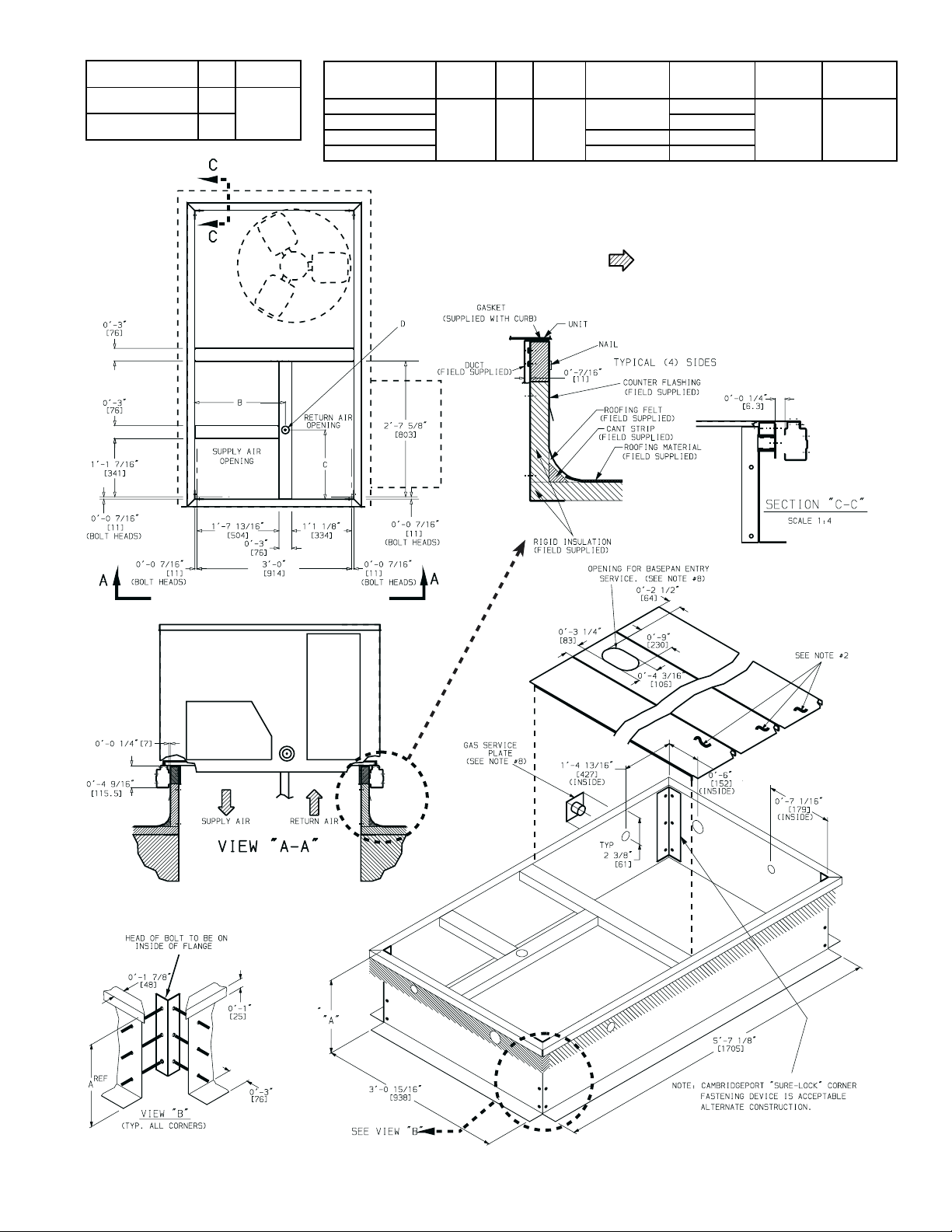
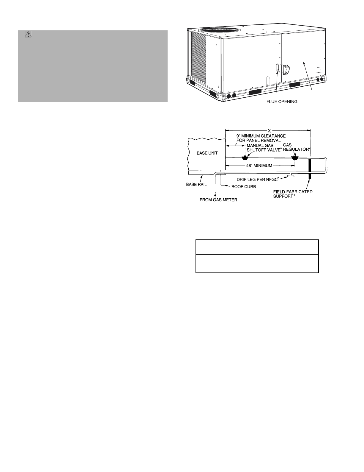
I. STEP 1 — PROVIDE UNIT SUPPORT
A. Roof Curb
Assemble and install accessory roof curb in accordance with
instructions shipped with curb. See Fig. 3. Install insulation,
cant strips, roofing felt, and counter flashing as shown. Duct-
work must be attached to curb, not to the unit. The accessory
thru-the-bottom power and gas connection package must be
installed before the unit is set on the roof curb. If field-
installed (thru-the-roof curb) gas connections are desired, use
factory-supplied
to mount the thru-the-roof curb connection to the roof curb.
Gas connections and power connections to the unit must be
field installed after the unit is installed on the roo f curb.
If electric and control wiring is to be routed through the
basepan, attach the accessory thru-the-bottom service connections to the basepan in accordance with the accessory
installation instructions.
IMPORTANT: The gasketing of the unit to the roof curb is
critical for a watertight seal. Install gasket supplied with the
roof curb as shown in Fig. 3. Improperly applied gasket can
result in air leaks and poor unit performance.
Curb should be level. Unit leveling tolerances are shown in
Fig. 4. This is necessary for unit drain to function properly.
Refer to Accessory Roof Curb Installation Instructions for
additional information as required.
1
/2 psig will cause g as valve damage
1
/2 psig, it must be
1
/2 psig or less, a
INSTALLATION
3
/4-in. pipe coupling and gas plate assembly
Page 2
—2—
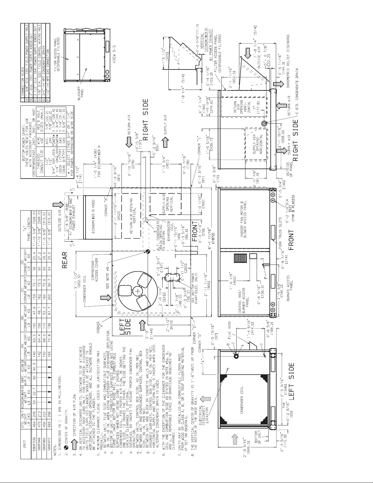
Fig. 1A — Base Unit Dimensions — 580F036-072
Page 3
—3—
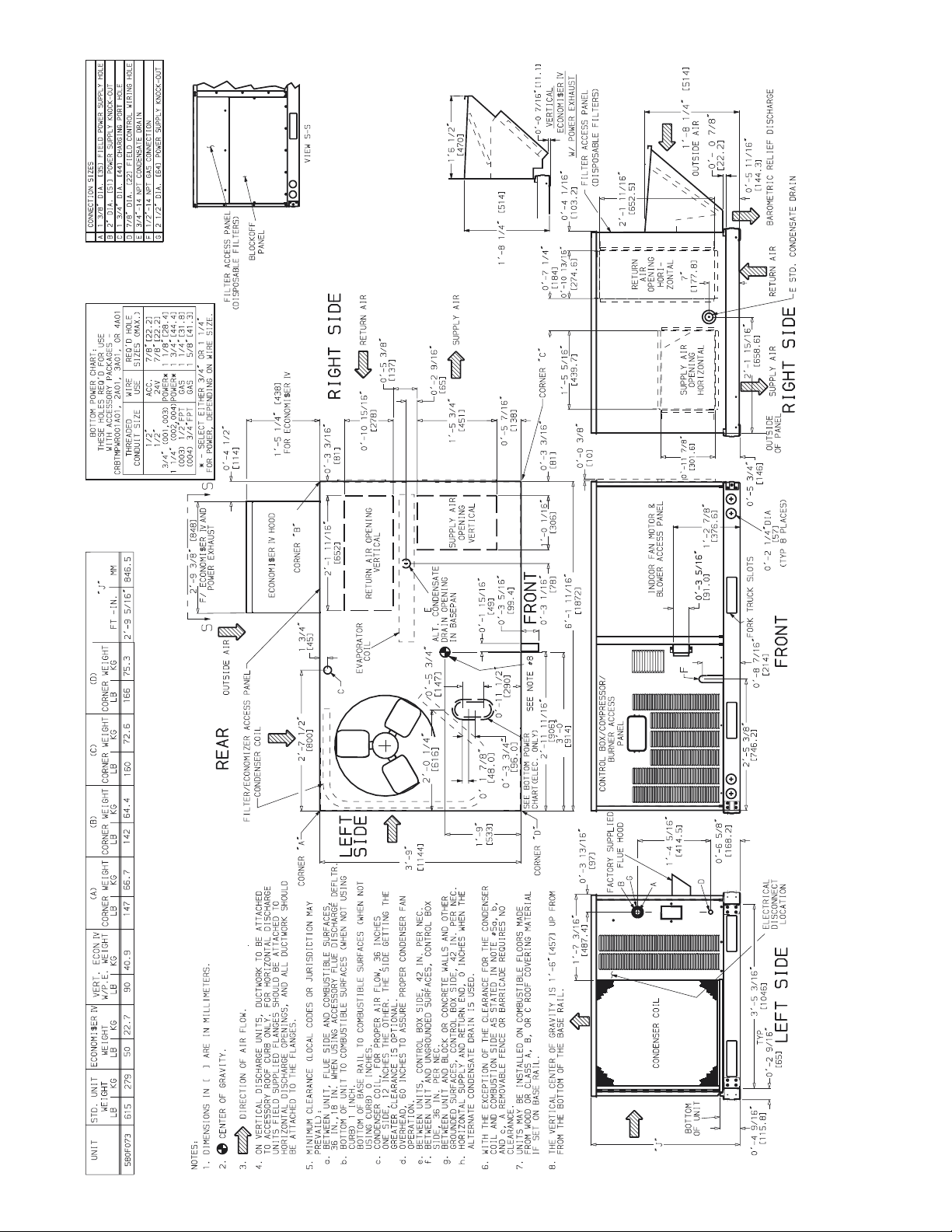
Fig. 1B — Base Unit Dimensions — 580F073
Page 4
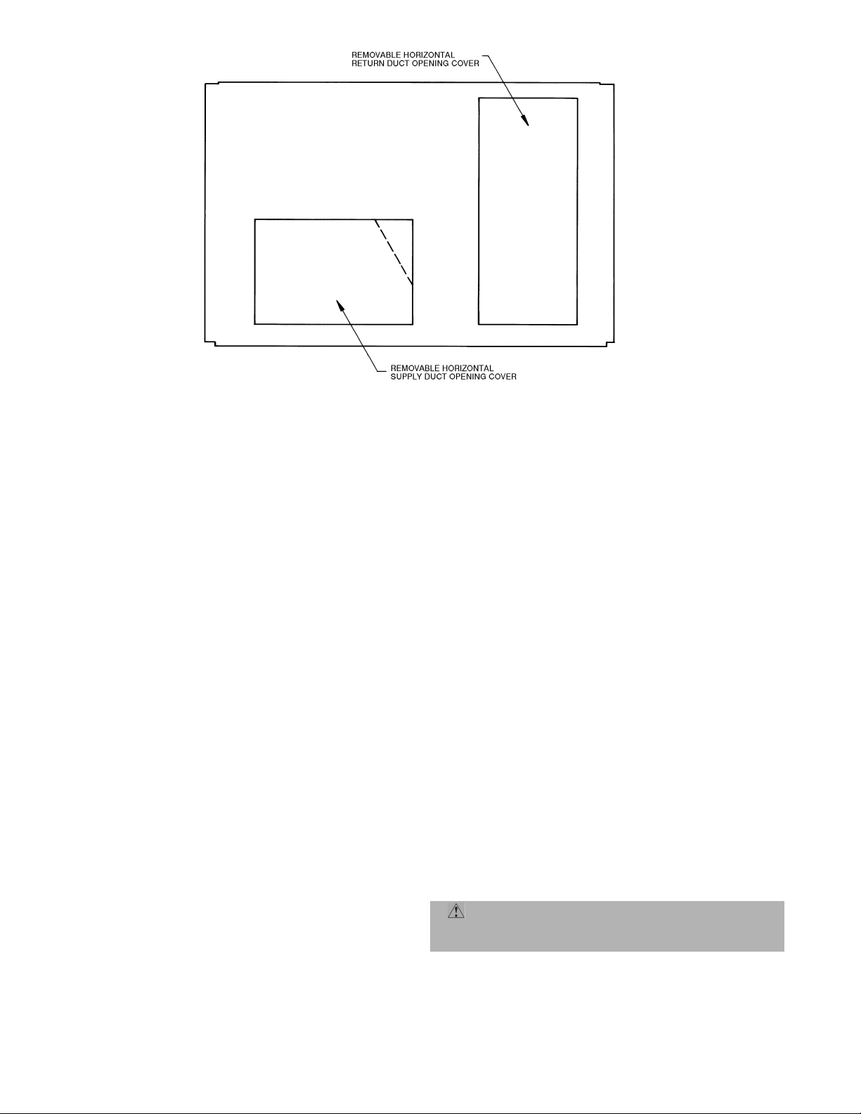
Fig. 2 — Horizontal Conversion Panels
B. Slab Mount (Horizontal Units Only)
Provide a level concrete slab tha t extends a minimum of 6 in.
beyond unit cabi ne t. I nsta ll a grav el apr on in f ron t of con dens er
coil air inlet to prevent grass and foliage from obstructing airflow.
NOTE: Horizontal units may be installed on a roof curb if
required.
C. Alternate Unit Support
A non-combustible sleepe r rail can be used in the unit curb
support area. If sleeper rails cannot be used, support the
long sides of the unit with a minimum of 3 equally spaced
4-in. x 4-in. pads on each side.
II. STEP 2 — FIELD FABRICATE DUCTWORK
Secure all ducts to roof curb and building s tructure on verti cal ducted units. Do not connect ductwork to unit. For h or izontal applications, fiel d-supplie d flanges sh ould b e attach ed
to horizontal duct openings and all ductwork should be
secured to the flanges. Insulate and weatherproof all external ductwork, joints , and roo f openings with counter flashing
and mastic in accordance with applicable codes.
Ducts passing through a n unc ondit i one d spa ce must be insulated and covered with a vapor barrier.
If a plenum return is used on a vertical unit, the return
should be ducted through the roof deck to comply with applicable fire codes.
A minimum clearance is not required around ductwork. Cabinet return air static pressure (a negative condition) should
not exceed 0.35 in. wg with economizer or 0.45 in. wg without economizer.
These units are designed for a minimum continuous heating
return-air temperature of 50 F (dry bulb), or an intermittent
operation down to 45 F (dry bulb), such as when used with a
night set-back thermostat.
To operate at lower return-air temperatures, a field-supplied
outdoor air temperature control must be used to initiate both
stages of heat when the temperature is below 45 F. Indoor
comfort may be compromised when these lower air temperatures are used with insufficient heating temperature rise.
III. STEP 3 — INSTALL EXTERNAL TRAP FOR CONDENSATE DRAIN
The unit’s
3
/4-in. condensate drain connections are located
on the bottom and side of the unit. Unit discharge connections do not determine the use of drain connections; either
drain connection can be used with vertical or horizontal
applications.
When using the standard side drain connection, make sure
the plug (Red) in the alternate bottom connection is tight
before installing the unit.
To use the bottom drain connection for a roof curb installation,
relocate the factory-i nstalle d plug (Re d) from t he bott om connection to the side connection. The center dr ain plug l ooks like
a star connection, however it can be removed with a
1
/2-in.
socket drive. See Fig. 5A. The piping for the condensate drain
and external trap can be completed after the unit is in place.
All units must have an external trap for condensate drainage.
Install a trap at least 4-in. deep and protect against freeze-up. If
drain line is installed downstream from the external trap, pitch
the line away fr om the unit at 1 in. per 10 ft of r un. Do not use a
pipe size smaller than the unit connection (
3
/4 in.). See Fig. 5B.
IV. STEP 4 — RIG AND PLACE UNIT
Inspect unit for transportation damage. File any claim with
transportation agency. Keep unit upright and do not drop.
Spreader bars are not required if top crating is left on unit.
Rollers may be used to move unit across a roof. Level by
using unit frame as a ref erence. See Table 1 and Fi g. 6 for
additional information.
Lifting holes are provided in base rails as shown in Fig. 1A
and 1B. Refer to rigging instructions on unit.
CAUTION: All panels must be in place when rigging.
Unit is not designed for handling by a fork truck. Damage
to unit may result.
—4—
Page 5
ROOF CURB
ACCESSORY
CRRFCURB001A01
CRRFCURB002A01
A UNIT SIZE
1′-2″
[356]
2′-0″
[610]
580F
036-073
1′-4″
[406]
D ALT
DRAIN
HOLE
13/4″
[44.5]
GAS POWER CONTROL
3
/4″ [19] NPT
1
/2″ [12.7] NPT3/4″ [19] NPT
3
/4″ [19] NPT 11/4″ [31.7]
NOTES:
1. Roof curb accessory is shipped disassembled.
2. Insulated panels.
3. Dimensions in [ ] are in millimeters.
4. Roof curb, galvanized steel.
5. Attach ductwork to curb (flanges of duct rest on curb).
6. Service clearance: 4 ft on each side.
CONNECTOR
PKG. ACCY.
BC
CRBTMPWR001A01
CRBTMPWR002A01 1
CRBTMPWR003A01
1′-9
11
[551]
/16″
CRBTMPWR004A01
7. Direction of airflow.
8. Connector packages CRBTMPWR001A01 and 2A01 are for
thru-the-curb type gas. Packages CRBTMPWR003A01 and
4A01 are for thru-the-bottom type gas connections.
3
/4″ [19] NPT
1
/4″ [31.7]
1
/2″
[12.7]
NPT
ACCESSORY
POWER
1
/2″
[12.7]
NPT
Fig. 3 — Roof Curb
—5—
Page 6
MAXIMUM ALLOWABLE
DIFFERENCE (in.)
A-B B-C A-C
0.5 1.0 1.0
Fig. 4 — Unit Leveling Tolerances
DRAIN PLUG
NOTE: Drain plug is shown in factory-installed position.
DRAIN PLUGHORIZONTAL
Fig. 5A — Condensate Drain Pan
NOTE: Trap should be deep enough to offset maximum unit static dif-
ference. A 4-in. trap is recommended.
Fig. 5B — Condensate Drain Piping Details
A. Positioning
Maintain cleara nce around and abov e unit to provide mini mum distance from combustible materials, proper airflow,
and service access. See Fi g. 1A and 1B. A properly positioned
unit will have the fol lo wing c l ea ranc es be twe en uni t and r o of
1
curb:
/4-in. clearance between roof curb and base rails on
each side and duct end of unit; 1/4-in. clearance between roof
curb and condenser coil end of unit . (See Fig. 3, section C-C.)
Do not install unit in an indoor location. Do not locate unit
air inlets near exhaust vents or other sources of contaminated air.
Be sure that unit is installed such that snow will not block
the combustion intake or flue outlet.
Unit may be installed directly on wood flooring or on Class
A, B, or C roof-covering material when roof curb is used.
Although unit is weatherproof, guard against water from
higher level runoff and overhangs.
Flue vent discharge must have a minimum horizontal clearance of 4 ft from electric and gas meters, gas regulators, and
gas relief equipment.
Minimum distance between unit and other electrically live
parts is 48 inches.
Flue gas can deteriorate building materials . Orie nt unit suc h
that flue gas will not affect building materials.
Adequate combustion-air space must be provided for
proper operation of this equipment. Be sure that installation
complies with all local codes and Section 5.3, Air for Combustion and Ventilation, NFGC (National Fuel Gas Code), and
ANSI (American National Standards Institute) Z223.1, and
NFPA (National Fire Protectio n As so ci atio n) 5 4 TI A -54 -84- 1.
In Canada, installation must be in accordance with the
CAN1-B149 installation codes for gas burning appliances.
After unit is in position, remove rigging skids and shipping
materials.
V. STEP 5 — INSTALL FLUE HOOD
Flue hood is shipped screwed to the basepan beside the
burner compartment access panel. Remove from shipping
location and using screws provided, install flue hood and
screen in location shown in Fig. 7.
VI. STEP 6 — INSTALL GAS PIPING
Unit is equipped for use wi th type of gas shown on nameplate. Refer to local building codes, or in the absence of local
codes, to ANSI Z223.1 entitled National Fuel Gas Code. In
Canada, installation must be in accordance with the
CAN1.B149.1 and CAN1.B149.2 installation codes for gas
burning appliances.
For natural gas applications, gas pressure at unit gas connection must not be less than 4 in. wg or greater than
13.0 in. wg while unit is oper atin g. On 580F04 8,0 60,072 high
heat units, the gas pressure at unit gas connection must not
be less than 5 in. wg or greater than 13 in. wg while the unit
is operating. For propane applications, the gas pressure
must not be less than 5 in. wg or greater than 13 in. wg at
the unit connection.
Size gas supply piping for 0.5 in. wg maximum pressure
drop. Do not use supply pipe smaller than unit gas connection. Support gas pipi ng as shown in the ta ble in Fig. 8. For
example, a
3
/4-in. gas pipe must have one field-fabricated
support beam every 8 ft. Therefore, an 18-ft long gas pipe
would have a minimum of 2 support beams, a 48-ft long pipe
would have a minimum of 6 support beams.
See Fig. 8 for typical pipe guide and locations of external
manual main shutoff valve.
CAUTION: When connecting the gas line to the
unit gas valve, the installer MUST use a backup
wrench to prevent valve damage.
—6—
Page 7
NOTES:
1. Dimensions in ( ) are in millimeters.
2. Hook rigging shackles through holes in base rail, as shown in
detail “A.” Holes in base rails are centered around the unit center
of gravity. Use wooden top skid when rigging to prevent rigging
straps from damaging unit.
3. Unit weights do not include economizer. See Table 1 for economizer weights.
CAUTION: All panels must be in place when rigging. Unit
is not designed for handling with a fork truck. Damage to unit
may result.
580F UNIT SIZE
036 510 231
048 520 236
060 540 245
072 615 279
073 665 302
Fig. 6 — Rigging Details
MAX WEIGHT “A” “B” “C”
Lb Kg in. mm in. mm in. mm
73.69 1872 37.50 953 33.35 845
—7—
Page 8
Table 1 — Physical Data
580F UNIT SIZE 036 048 060 072 073
NOMINAL CAPACITY (tons) 34566
OPERATING WEIGHT (lb)
Unit
Al/Al* 460 470 490 565 615
Al/Cu* 465 476 497 576 —
Cu/Cu* 468 482 505 587 —
Economizer
EconoMi$er IV 50 50 50 50
Roof Curb† 115 115 115 115 115
COMPRESSOR Reciprocating Scroll
Quantity 11111
No. Cylinders (per Circuit) 22222
Oil (oz) 50 50 50 54 60
REFRIGERANT TYPE R-22
Expansion Device Fixed Orifice Metering Device
Operating Charge (lb-oz)
Circuit 1 4-4 6-6 6-14 9-0 11-0
Circuit 2 —————
CONDENSER COIL Enhanced Copper Tubes, Aluminum Lanced Fins
Rows...Fins/in. 1...17 2...17 2...17 2...17 2...17
Total Face Area (sq ft) 8.36 8.36 10.42 10.42 16.5
CONDENSER FAN Propeller Type
Nominal Cfm 3500 4000 4000 4000 4100
Quantity...Diameter (in.) 1...22.0 1...22.0 1...22.0 1...22.0 1...22.0
Motor Hp...Rpm
Watts Input (Total) 325 325 325 325 320
EVAPORATOR COIL Enhanced Copper Tubes, Aluminum Double-Wavy Fins
Rows...Fins/in. 2...15 2...15 3...15 4...15 4...15
Total Face Area (sq ft) 4.17 5.5 5.5 5.5 5.5
EVAPORATOR FAN Centrifugal Type
Quantity...Size (in.) Std 1...10 x 10 1...10 x 10 1...11 x 10 1...10 x 10 1...10 x 10
Type Drive Std Direct Direct Direct Belt Belt
Nominal Cfm 1200 1600 2000 2100 2100
Maximum Continuous Bhp Std .34 .75 1.20 2.40 2.40
Motor Frame Size Std 48 48 48 56 56
Nominal Rpm High/Low (Direct Drive) Std 860/800 1075/970 1075/970 — —
Fan Rpm Range Std — — — 1070-1460 1070-1460
Motor Bearing Type Ball Ball Ball Ball Ball
Maximum Allowable Rpm 2100 2100 2100 2100 2100
Motor Pulley Pitch Diameter Min/Max (in.) Std — — — 2.8/3.8 2.8/3.8
Nominal Motor Shaft Diameter (in.) Std
Fan Pulley Pitch Diameter (in.) Std ———4.54.5
Belt, Quantity...Type...Length (in.) Std — — — 1...A...40 1...A...40
Pulley Center Line Distance (in.) Std — — — 14.7-15.5 14.7-15.5
Speed Change per Full Turn of Std —— — 8080
Movable Pulley Flange (rpm) Alt 48 70 80 — —
Movable Pulley Maximum Full Turns Std ——— 55
From Closed Position Alt 556——
Factory Setting Std —— — 33
Factory Speed Setting (rpm) Std — — — 1226 1226
Fan Shaft Diameter at Pulley (in.)
Alt 1...10 x 10 1...10 x 10 1...10 x 10 — —
High-Static 1...10 x 10 1...10 x 10 1...11 x 10 1...10 x 10 1...10 x 10
Alt Belt Belt Belt — —
High-Static Belt Belt Belt Belt Belt
Alt 1.20 1.20 1.30/2.40** — —
High-Static 2.40 2.40 2.90 2.90 2.90
Alt 48 48 56 — —
High-Static 56 56 56 56 56
Alt —————
High-Static —————
Alt 685-1045 770-1175 878-1192 — —
High-Static 1075-1455 1075-1455 1300-1685 1300-1685 1300-1685
Alt 1.9/2.9 1.9/2.9 2.4/3.4 — —
High-Static 2.8/3.8 2.8/3.8 3.4/4.4 3.4/4.4 3.4/4.4
Alt
High-Static
Alt 4.5 4.0 4.5 — —
High-Static 4.5 4.5 4.5 4.5 4.5
Alt 1...A...34 1...A...34 1...A...39 — —
High-Static 1...A...39 1...A...39 1...A...40 1...A...40 1...A...40
Alt 10.0-12.4 10.0-12.4 14.7-15.5 — —
High-Static 10.0-12.4 10.0-12.4 14.7-15.5 14.7-15.5 14.7-15.5
High-Static 65 65 60 60 60
High-Static 66555
Alt 33 3——
High-Static 3
Alt 829 932 1035 — —
High-Static 1233 1233 1416 1416 1416
LEGEND
Al — Aluminum
Bhp — Brake Horsepower
Cu — Copper
*Evaporator coil fin material/condenser coil fin material. Contact your local
Bryant representative for details about coated fins.
†Weight of 14-in. roof curb.
**Single phase/three-phase.
1
/4...1100
1
/
2
1
/
2
5
/
8
1
/
2
5
/
8
††Rollout switch lockout is manually reset by interrupting power to unit or reset-
ting thermostat.
||California rated three-phase high heat models.
***Three phase standard high-heat models have heating input values as shown.
Single phase standard high heat models have one-stage heating with heating
input values as follows:
580FJV036115 — 115,000 Btuh
580FJV048150 — 150,000 Btuh
580FJV060150 — 150,000 Btuh
†††California SCAQMD compliant Low NO
that are controlled to 40 nanograms per joule or less.
1
/4...1100
1
/
1
/
5
/
31/
5
/
1
/4...1100
1
31/
/
2
5
/
8
5
/
8
2
5
/
8
2
2
8
2
8
1
/4...1100
5
/
8
——
5
/
8
31/
2
5
/
8
models have combustion products
x
50
1
/4...1100
5
/
7
/
31/
5
/
8
8
2
8
—8—
Page 9
Table 1 — Physical Data (cont)
580F UNIT SIZE 036 048 060 072 AND 073
FURNACE SECTION
Rollout Switch Cutout
Temp (F)†† 195 195 195 195
Burner Orifice Diameter
(in. ...drill size)
Natural Gas Std 074 .113...33 .113...33 .113...33 .113...33
Liquid Propane Alt 074 .089...43 .089...43 .089...43 .089...43
Thermostat Heat Anticipator
Setting (amps)
208/230 v and 575 Stage 1 .14 .14 .14 .14
460 v Stage 1 .14 .14 .14 .14
Gas Input (Btuh) CA High Output 3-Phase Units
Stage 2 .14 .14 .14 .14
Stage 2 .14 .14 .14 .14
Standard Units 074 74,000/— 74,000/— 74,000/— 74,000/—
(Stage 2/ Stage 1) 115*** 115,000/82,000 115,000/— 115,000/— 115,000/—
Low NOx Units 060N††† 60,000 60,000 60,000 —
Efficiency (Steady
State) (%) 80 80 80 80
Temperature Rise Range 074 25-55 25-55 25-55 25-55
Manifold Pressure (in. wg)
Natural Gas Std 3.5 3.5 3.5 3.5
Liquid Propane Alt 3.5 3.5 3.5 3.5
Gas Valve Quantity 1111
Gas Valve Pressure Range
Psig 0.180-0.487 0.180-0.487 0.180-0.487 0.180-0.487
in. wg 5.0-13.5 5.0-13.5 5.0-13.5 5.0-13.5
Field Gas Connection
Size (in.)
HIGH-PRESSURE SWITCH (psig)
Standard Compressor 450 ± 50 500 ± 50
Internal Relief (Differential)
Cutout 428 428
Reset (Auto.) 320 320
LOSS-OF-CHARGE (LOW-PRESSURE SWITCH) (psig)
Cutout 7 ± 3
Reset (Auto.) 22 ± 7
FREEZE PROTECTION
THERMOSTAT (F)
Opens 30 ± 5
Closes 45 ± 5
OUTDOOR-AIR INLET SCREENS Cleanable. Screen size and quantity varies with option selected.
RETURN-AIR FILTERS Throwaway
Quantity...Size (in.) 2...16 x 25 x 2
LEGEND
Al — Aluminum
Bhp — Brake Horsepower
Cu — Copper
*Evaporator coil fin material/condenser coil fin material. Contact your local rep-
resentative for details about coated fins.
†Weight of 14-in. roof curb.
**Single phase/three-phase.
114/115 .113...33 .113...33 .113...33 .113...33
149/150 — .129...30 .129...30 .129...30
060N .102...38 .102...38 .102...38 —
090N .102...38 .102...38 .102...38 —
120N — .116...32 .116...32 —
114/115 .089...43 .089...43 .089...43 .089...43
149/150 — .104...37 .104...37 .104...37
060N .082...45 .082...45 .082...45 —
090N .082...45 .082...45 .082...45 —
120N — .094...42 .094...42 —
114|| 115,000 — — —
149|| — 150,000 150,000 —
150*** — 150,000/120,000 150,000/120,000 150,000/120,000
090N††† 90,000 90,000 90,000 —
120N††† — 120,000 120,000 —
114/115 55-85 35-65 35-65 35-65
149/150 — 50-80 50-80 50-80
060N 20-50 20-50 20-50 —
090N 30-60 30-60 30-60 —
120N — 40-70 40-70 —
1
/
2
††Rollout switch lockout is manually reset by interrupting power to unit or reset-
ting thermostat.
||California rated three-phase high heat models.
***Three phase standard high-heat models have heating input values as shown.
Single phase standard high heat models have one-stage heating with heating
input values as follows:
580FJV036115 — 115,000 Btuh
580FJV048150 — 150,000 Btuh
580FJV060150 — 150,000 Btuh
†††California SCAQMD compliant Low NO
that are controlled to 40 nanograms per joule or less.
1
/
2
1
/
2
models have combustion products
x
1
/
2
—9—
Page 10
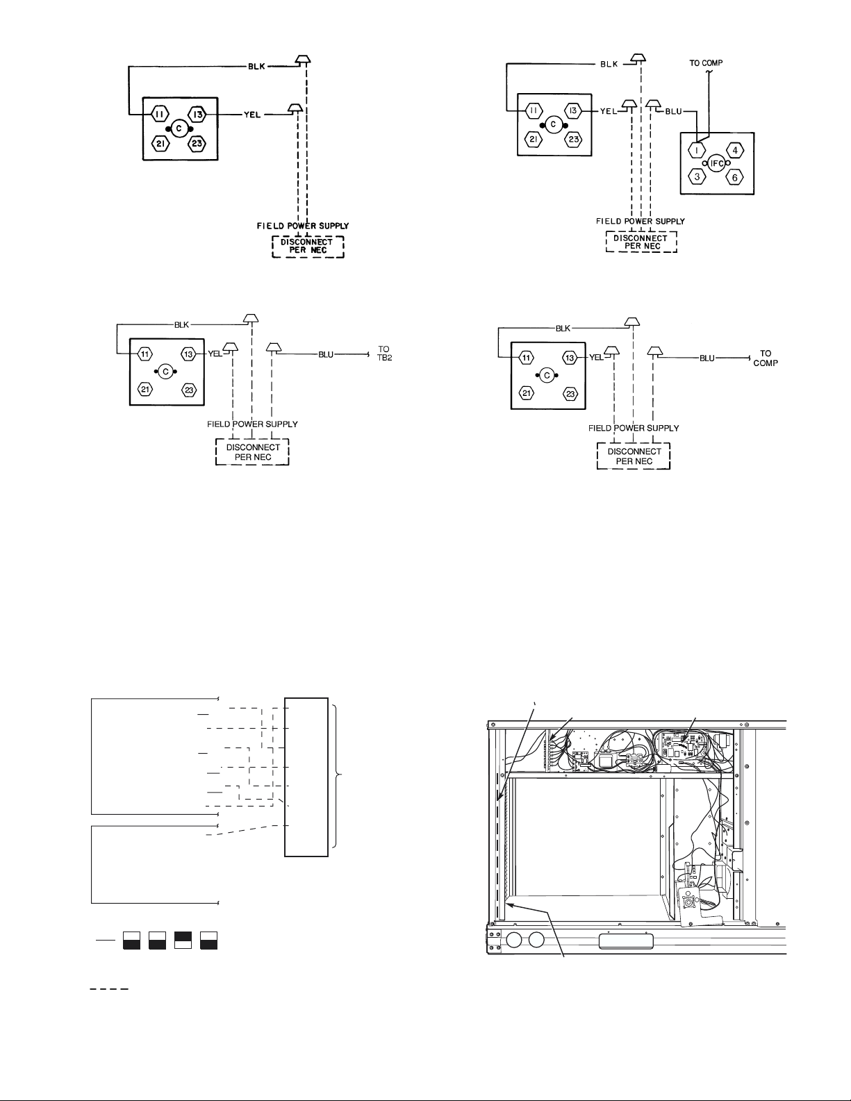
VII. STEP 7 — MAKE ELECTRICAL CONNECTIONS
WARNING: Unit cabinet must have an uninter-
rupted, unbroken electrical ground to minimize the possibility of personal injury if an electrical fault should occur.
This ground may consist of electrical wire connected to
unit ground lug in control compartment, or conduit
approved for electrical ground when installed in accordance with NEC (N a tio n al Electrical Code), ANSI/N FPA,
latest edition, and local electrical codes. Do not use gas
piping as an electrical ground. Failure to follow this
warning could result in the installer being liable for p ersonal injury of others.
BLOWER
ACCESS
PANEL
A. Field Power Supply
All units except 208/230-v units are factory wired for the
voltage shown on the na meplate. If the 208/230-v u nit is to
be connected to a 208-v power supply, the transformer must
be rewired by m oving the blac k wire with th e
1
/4-in. female
space connector from the 230-volt connection and moving to
the 208-volt
1
/4-in. male terminal on the primary side of the
transformer.
Refer to unit label diagram for additional information.
Pigtails are provided for fie ld wire connectio ns. Use factorysupplied splices or UL (Underwriters’ Laboratories)
approved copper/aluminum connector.
When installing units, provide a disconnect per the NEC.
All field wiring must comply with NEC and local require-
ments.
Install field wiring as foll ows:
1. Install conduit through side panel openings. Install
conduit between disconnect and control box.
2. Install power lines to terminal connections as shown
in Fig. 9.
Voltage to compressor terminals during operation must be
within voltage range indicated on unit nameplate (see
Tables 2A and 2B). On 3-phase units, voltages between
phases must be balanced within 2% and the current within
10%. Use the formula shown in the legend for Tables 2A and
2B, Note 2 to determine the percent of voltage imbalance.
Operation on impr op er lin e volta ge or excess ive phase imbalance constitutes abuse and may cause damage to electrical
components. Such operation would invalidate any applicable
Bryant warranty.
B. Field Control Wiring
Install a Bryant-approved accessory thermostat assembly
according to installation instructions included with the
accessory. Locate thermostat assembly on a solid wall in the
conditioned space to sense average temperature in accordance with thermostat installation instructions. Connect
thermostat wires to terminal board.
Route thermostat cable or equivalent single leads of colored
wire from subbase terminals through connector on unit to
low-voltage connections (shown in Fig. 10).
NOTE: For wire runs up 50 ft, use no. 18 AWG (American
Wire Gage) insulated wire (35 C minimum). For 50 to 75 ft,
use no. 16 AWG insulated wire (35 C minimum). For over
Fig. 7 — Flue Hood Details
LEGEND
NFGC — National Fuel Gas Code
*Field supplied.
NOTE: Follow all local codes.
SPACING OF SUPPORTS
STEEL PIPE
NOMINAL DIAMETER
(in.)
1
/
2
3
/4 or 1 8
1
1
/4 or larger 10
X
DIMENSION
(feet)
6
Fig. 8 — Gas Piping Guide (With Accessory
Thru-the-Curb Service Connections)
75 ft, use no. 14 AWG insulated wire (35 C minimum). All
wire larger than n o. 18 AWG cannot be dir ectly con nect ed to
the thermos tat and wi ll req uire a j unction box and s plice a t
the thermostat.
Pass the control wires thro ugh the hole provided i n the corner post; then feed w ires throug h the raceway buil t into the
corner post to the 24-v barri er located on the le ft side of the
control box. See Fig. 11. The raceway provides the UL
required clearance between high-voltage and low-voltage
wiring.
C. Heat Anticipator Settings
Set heat anticipator settings at 0.14 amp for the first stage
and 0.14 amp for second- stage heating, when available.
—10—
Page 11
208/230-1-60
208/230-3-60
460-3-60
(SIZES 072 AND 073)
575-3-60
(SIZES 072 AND 073)
LEGEND
C—Contactor
COMP — Compressor
IFC — Indoor-Fan Contactor
NEC — National Electrical Code
TB — Terminal Block
COOL STAGE 1
FAN
HEAT STAGE 1
COOL STAGE 2
HEAT STAGE 2
24 VAC HOT
24 VAC COM
N/A
OUTDOOR AIR
SENSOR
Y1/W2
G
W/W1
Y/Y2
O/W2
R
C
S1
S2
Fig. 9 — Power Wiring Connections
R
G
Y1
Y2
W1
W2
C
IPD/X
WIRE
CONNECTIONS
TO
LOW-VOLTAGE
SECTION
(CONNECTION
BOARD)
208/230-3-60
575-3-60, 460-3-60
(SIZES 036-060)
RACEWAY LOW VOLTAGE
CONNECTIONS
INTEGRATED GAS UNIT
CONTROLLER (IGC)
THERMOSTAT DIPSWITCH SETTINGS
ON
OFF
B
A
D
C
LEGEND
Field Wiring
NOTE: Underlined letter indicates active thermostat output when configured for A/C operation.
Fig. 10 — Low-Voltage Connections
HOLE IN END PANEL (HIDDEN)
Fig. 11 — Field Control Wiring Raceway
—11—
Page 12
Table 2A — Electrical Data (Without Convenience Outlet)
580F
UNIT
SIZE
036
(3 Tons)
048
(4 Tons)
060
(5 Tons)
072
(6 Tons)
073
(6 Tons)
NOMINAL
VO LTAGE
208/230-1-60
208/230-3-60
460-3-60
575-3-60
208/230-1-60
208/230-3-60
460-3-60
575-3-60
208/230-1-60
208/230-3-60
460-3-60
575-3-60
208/230-3-60
460-3-60
575-3-60
208/230-3-60
460-3-60
575-3-60
TYPE
High 5.2 19.4/19.4 25/25 19/19 109/109
High 2.6 8.9 15 9 57
High 2.6 6.3 15 7 56
High 5.2 25.9/25.9 30/30 25/25 124/124
High 2.6 13.8 20 13 62
High 2.6 9.7 15 10 49
High 7.5 28.9/28.9 35/35 29/29 174/174
High 3.4 13.5 20 13 93
High 3.4 9.9 15 11 76
High 7.5 34.7/34.7 40/40 34/34 205/205
High 3.4 16.2 20 16 103
High 3.4 11.9 15 13 86
High 7.5 34.7/34.7 40/40 34/34 205/205
High 3.4 16.2 20 16 103
High 3.4 11.9 15 13 86
VO LTAGE
IFM
Std
Alt 4.9 26.6/26.6 35/35 26/26 111/111
Std
Alt 4.9 19.1/19.1 25/25 19/19 90/ 90
Std
Alt 2.1 8.4 15 8 48
Std
Alt 2.1 6.0 15 7 37
Std
Alt 4.9 35.4/35.4 45/45 34/34 133/133
Std
Alt 4.9 25.6/25.6 30/30 25/25 105/105
Std
Alt 2.1 13.3 20 13 53
Std
Alt 2.1 9.3 15 10 42
Std
Alt 6.6 44.0/44.0 60/60 42/42 184/184
Std
Alt 5.2 26.6/26.6 35/35 26/26 148/148
Std
Alt 2.6 13.5 20 13 81
Std
Alt 2.6 9.9 15 11 65
Std
Std
Std
Std
Std
Std
RANGE
Min Max RLA LRA Hp FLA FLA MCA MOCP† FLA LRA
187 254 16.2 96.01/41.4
187 254 10.2 75.01/41.4
414 508 4.4 40.01/40.8
518 632 3.7 31.01/40.8
187 254 23.3 118.01/41.4
187 254 15.4 90.01/41.4
414 508 8.3 45.01/40.8
518 632 6.4 36.01/40.8
187 254 28.8 147.01/41.4
187 254 16.0 114.01/41.4
414 508 7.4 64.01/40.8
518 632 6.2 52.01/40.8
187 254 20.6 146.01/41.4
414 508 9.5 73.01/40.9
518 632 7.6 58.41/40.6
187 254 20.6 146.01/41.4
414 508 9.5 73.01/40.9
518 632 7.6 58.41/40.6
LEGEND
FLA — Full Load Amps
HACR — Heating, Air Conditioning and Refrigeration
IFM — Indoor (Evaporator) Fan Motor
LRA — Locked Rotor Amps
MCA — Minimum Circuit Amps
MOCP — Maximum Overcurrent Protection
NEC — National Electrical Code
OFM — Outdoor (Condenser) Fan Motor
RLA — Rated Load Amps
*Used to determine minimum disconnect per NEC.
†Fuse or HACR circuit breaker.
NOTES:
1. In compliance with NEC requirements for multimotor and combination load equipment (refer
to NEC Articles 430 and 440), the overcurrent protective device for the unit shall be fuse or
HACR breaker. Canadian units may be fuse or circuit breaker.
2. Unbalanced 3-Phase Supply Voltage
Never operate a motor where a phase imbalance in supply voltage is greater than 2%.
the following formula to determine the percent of voltage imbalance.
% Voltage Imbalance
= 100 x
Example: Supply voltage is 460-3-60.
Determine maximum deviation from average voltage.
(AB) 457 – 452 = 5 v
(BC) 464 – 457 = 7 v
(AC) 457 – 455 = 2 v
max voltage deviation from average voltage
AB = 452 v
BC = 464 v
AC = 455 v
Average Voltage =
average voltage
452 + 464 + 455
1371
=
3
= 457
3
COMPR
(ea)
Use
OFM
(ea)
Maximum deviation is 7 v.
Determine percent of voltage imbalance.
% Voltage Imbalance = 100 x
This amount of phase imbalance is satisfactory as it is below the maximum allowable 2%.
IMPORTANT: If the supply voltage phase imbalance is more than 2%, contact your local electric
utility company immediately.
3. For units with power exhaust: If a single power source is to be used, size wire to include
power exhaust MCA and MOCP. Check MCA and MOCP when power exhaust is powered
through the unit (must be in accordance with NEC and/or local codes). Determine the new
MCA including the power exhaust using the following formula:
MCA New = MCA unit only + MCA of Power Exhaust
For example, using a 580F060 unit with MCA = 28.9 and MOCP = 35, with
CRPWREXH030A01 power exhaust.
MCA New = 28.9 amps + 1.6 amps = 30.5 amps
If the new MCA does not exceed the published MOCP, then MOCP would not change. The
MOCP in this example is 35 amps, the MCA New is below 35, therefore the MOCP is
acceptable. If “MCA New” is larger than the published MOCP, raise the MOCP to the next
larger size. For separate power, the MOCP for the power exhaust will be 15 amps per NEC.
COMBUSTION
IFM
3.5
3.5
1.3
1.3
3.5
3.5
1.8
1.8
5.9
5.9
3.1
3.1
5.2
2.6
2.6
5.2
2.6
2.6
FAN MOTOR
FLA
.6
.6
.3
.3
.6
.6
.3
.3
.6
.6
.3
.3
.6
.3
.3
.6
.3
.3
= 1.53%
POWER EXHAUST
PAR T N O.
CRPWREXH030A01 1.6 N/A 0.64 15
CRPWREXH021A01 N/A 0.9 N/A 15
CRPWREXH022A01 3.3 N/A 1.32 15
CRPWREXH023A01 N/A 1.8 N/A 15
CRPWREXH028A01 1.7 N/A 0.68 15
CRPWREXH029A01 N/A 1.0 N/A 15
POWER SUPPLY
25.2/25.2 30/30 24/24 106/106
17.7/17.7 25/25 17/17 85/ 85
7.6 15 7 44
5.5 15 6 35
34.0/34.0 40/40 32/32 129/129
24.2/24.2 30/30 23/23 101/101
13.0 20 13 51
9.2 15 10 41
43.3/43.3 60/60 42/42 161/161
27.3/27.3 35/35 27/27 128/128
13.2 20 13 71
9.7 15 11 58
32.4/32.4 40/40 31/31 180/180
15.4 20 15 90
11.4 15 12 75
32.4/32.4 40/40 31/31 180/180
15.4 20 15 90
11.4 15 12 79
7
457
MCA
(230 v)
MCA
(460 v)
MCA
(575 v)
DISCONNECT
SIZE*
(for separate
power source)
MOCP
—12—
Page 13
Table 2B — Electrical Data (With Convenience Outlet)
580F
UNIT
SIZE
036
(3 Tons)
048
(4 Tons)
060
(5 Tons)
072
(6 Tons)
073
(6 Tons)
NOMINAL
VO LTAGE
208/230-1-60
208/230-3-60
460-3-60
575-3-60
208/230-1-60
208/230-3-60
460-3-60
575-3-60
208/230-1-60
208/230-3-60
460-3-60
575-3-60
208/230-3-60
460-3-60
575-3-60
208/230-3-60
460-3-60
575-3-60
IFM
TYPE
Std
Std
High 5.2 24.2/24.2 30/30 25/25 114/114
Std
High 2.6 11. 1 15 11 59
Std
High 2.6 8.0 15 9 58
Std
Std
High 5.2 30.7/30.7 35/35 31/31 129/129
Std
High 2.6 16. 0 20 16 64
Std
High 2.6 11. 4 15 12 51
Std
Std
High 7.5 33.7/33.7 40/40 34/34 179/179
Std
High 3.4 15. 6 20 16 96
Std
High 3.4 11. 7 15 13 77
Std
High 7.5 39.5/39.5 45/45 39/39 210/210
Std
High 3.4 18.4 25 18 105
Std
High 3.4 13. 7 20 15 90
Std
High 7.5 39.5/39.5 45/45 39/39 210/210
Std
High 3.4 18.4 25 18 105
Std
High 3.4 13. 7 20 15 90
VO LTAGE
RANGE
Min Max RLA LRA Hp FLA FLA MCA MOCP† FLA LRA
187 254 16.2 96.01/41.4
Alt 4.9 32.6/32.6 40/40 31/31 116/116
187 254 10.2 75.01/41.4
Alt 4.9 23.9/23.9 30/30 25/25 95/ 95
414 508 4.4 40.01/40.8
Alt 2.1 10.6 15 11 50
518 632 3.7 31.01/40.8
Alt 2.1 7.7 15 9 39
187 254 23.3 118.01/41.4
Alt 4.9 41.4/41.4 50/50 40/40 138/138
187 254 15.4 90.01/41.4
Alt 4.9 30.4/30.4 35/35 30/30 110/110
414 508 8.3 45.01/40.8
Alt 2.1 15.5 20 15 55
518 632 6.4 36.01/40.8
Alt 2.1 11.1 15 12 44
187 254 28.8 147.01/41.4
Alt 6.6 50.0/50.0 60/60 48/48 188/188
187 254 16.0 114.01/41.4
Alt 5.2 31.4/31.4 40/40 32/32 153/153
414 508 7.4 64.01/40.8
Alt 2.6 15.6 20 15 83
518 632 6.2 52.01/40.8
Alt 2.6 11.7 15 12 67
187 254 20.6 146.01/41.4
414 508 9.5 73.01/40.6
518 632 7.6 58.41/40.6
187 254 20.6 146.01/41.4
414 508 9.5 73.01/40.6
518 632 7.6 58.41/40.6
LEGEND
FLA — Full Load Amps
HACR — Heating, Air Conditioning and Refrigeration
IFM — Indoor (Evaporator) Fan Motor
LRA — Locked Rotor Amps
MCA — Minimum Circuit Amps
MOCP — Maximum Overcurrent Protection
NEC — National Electrical Code
OFM — Outdoor (Condenser) Fan Motor
RLA — Rated Load Amps
*Used to determine minimum disconnect per NEC.
†Fuse or HACR circuit breaker.
NOTES:
1. In compliance with NEC requirements for multimotor and combination load equipment (refer
to NEC Articles 430 and 440), the overcurrent protective device for the unit shall be fuse or
HACR breaker. Canadian units may be fuse or circuit breaker.
2. Unbalanced 3-Phase Supply Voltage
Never operate a motor where a phase imbalance in supply voltage is greater than 2%.
the following formula to determine the percent of voltage imbalance.
% Voltage Imbalance
= 100 x
Example: Supply voltage is 460-3-60.
Determine maximum deviation from average voltage.
(AB) 457 – 452 = 5 v
(BC) 464 – 457 = 7 v
(AC) 457 – 455 = 2 v
max voltage deviation from average voltage
AB = 452 v
BC = 464 v
AC = 455 v
Average Voltage =
average voltage
452 + 464 + 455
1371
=
3
= 457
3
COMPR
(ea)
Use
OFM
(ea)
IFM
Maximum deviation is 7 v.
Determine percent of voltage imbalance.
% Voltage Imbalance = 100 x
This amount of phase imbalance is satisfactory as it is below the maximum allowable 2%.
IMPORTANT: If the supply voltage phase imbalance is more than 2%, contact your local electric
utility company immediately.
3. For units with power exhaust: If a single power source is to be used, size wire to include
power exhaust MCA and MOCP. Check MCA and MOCP when power exhaust is powered
through the unit (must be in accordance with NEC and/or local codes). Determine the new
MCA including the power exhaust using the following formula:
MCA New = MCA unit only + MCA of Power Exhaust
For example, using a 580F060 unit with MCA = 28.9 and MOCP = 35, with
CRPWREXH030A01 power exhaust.
MCA New = 28.9 amps + 1.6 amps = 30.5 amps
If the new MCA does not exceed the published MOCP, then MOCP would not change. The
MOCP in this example is 35 amps, the MCA New is below 35, therefore the MOCP is
acceptable. If “MCA New” is larger than the published MOCP, raise the MOCP to the next
larger size. For separate power, the MOCP for the power exhaust will be 15 amps per NEC.
COMBUSTION
FAN MOTOR
FLA
3.5
3.5
1.3
1.3
3.5
3.5
1.8
1.8
5.9
5.9
3.1
3.1
5.2
2.6
2.6
5.2
2.6
2.6
POWER EXHAUST
CRPWREXH030A01 1.6 N/A 0.64 15
CRPWREXH021A01 N/A 0.9 N/A 15
CRPWREXH022A01 3.3 N/A 1.32 15
CRPWREXH023A01 N/A 1.8 N/A 15
CRPWREXH028A01 1.7 N/A 0.68 15
CRPWREXH029A01 N/A 1.0 N/A 15
.6
.6
.3
.3
.6
.6
.3
.3
.6
.6
.3
.3
.6
.3
.3
.6
.3
.3
= 1.53%
PAR T N O.
POWER SUPPLY
31.2/31.2 35/35 30/30 111/111
22.5/22.5 25/25 23/23 90/ 90
9.8 15 10 47
7.2 15 8 36
40.0/40.0 45/45 38/38 134/134
29.0/29.0 35/35 29/29 106/106
15.2 20 15 53
10.9 15 12 42
49.3/49.3 60/60 47/47 166/166
32.1/32.1 40/40 32/32 133/133
15.3 20 15 74
11.5 15 13 60
37.2/37.2 45/45 37/37 184/184
17.6 20 17 92
13.1 20 14 77
37.2/37.2 45/45 37/37 184/184
17.6 20 17 92
13.1 20 14 77
7
457
MCA
(230 v)
MCA
(460 v)
MCA
(575 v)
DISCONNECT
SIZE*
(for separate
power source)
MOCP
—13—
Page 14
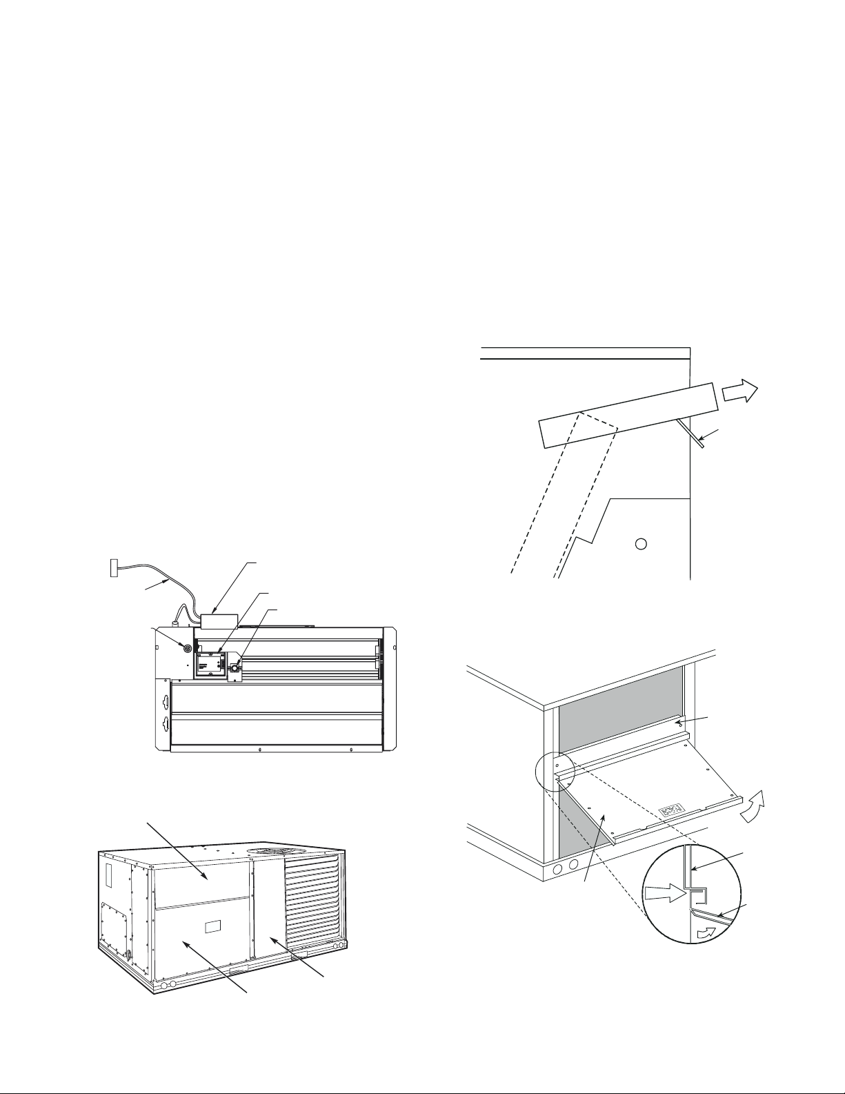
VIII. STEP 8 — ADJUST FACTORY-INSTALLED OPTIONS
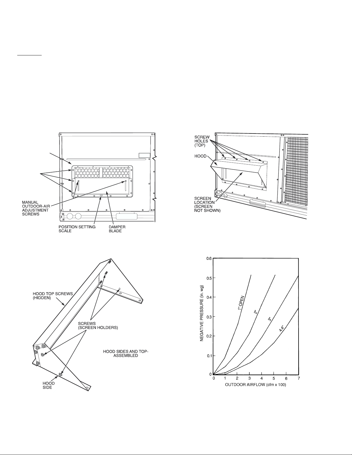
A. Manual Outdoor-Air Damper
The outdoor-air hood and screen are attached to the basepan
at the bottom of the unit for shipping.
Assembly:
1. Determine quantity of ventilation required for building. Record amount for use in Step 8.
2. Remove and save outdoor air opening panel and
screws. See Fig. 12.
3. Separate hood and screen from basepan by removing
the 4 screws securing them. Save al l screws.
4. Replace evaporator coil access panel.
5. Place hood o n front of outdo or air open ing panel. See
Fig. 13 for hood details. Secure top of hood with the
4 screws removed in Step 3. See Fig. 14.
OUTDOOR
AIR OPENING
PANEL
3 SCREWS
(SIDE)
6. Remove and save 6 screws (3 on each side) from sides
of the manual outdoor-air damper.
7. Align screw holes on hood with screw holes on side of
manual outdoor-air da mper. See Fig. 13 and 14. Secure hood with 6 screws from Step 6.
8. Adjust minimum positio n setti ng of the dampe r bla d e
by adjusting the manual outdoor-air adjustment
screws on the front of th e damper bla de. See Fig. 12.
Slide blade vertically until it is in the appropriate position determined by Fig. 15. Tighten screws.
9. Remove and save scr ews currently on sides of hood.
Insert screen. Secure screen to hood using the screws.
See Fig. 14.
Fig. 12 — Damper Panel with Manual Outdoor-Air
Damper Installed
Fig. 14 — Outdoor-Air Damper with
Hood Attached
Fig. 13 — Outdoor-Air Hood Details
Fig. 15 — Outdoor-Air Damper Position Setting
—14—
Page 15
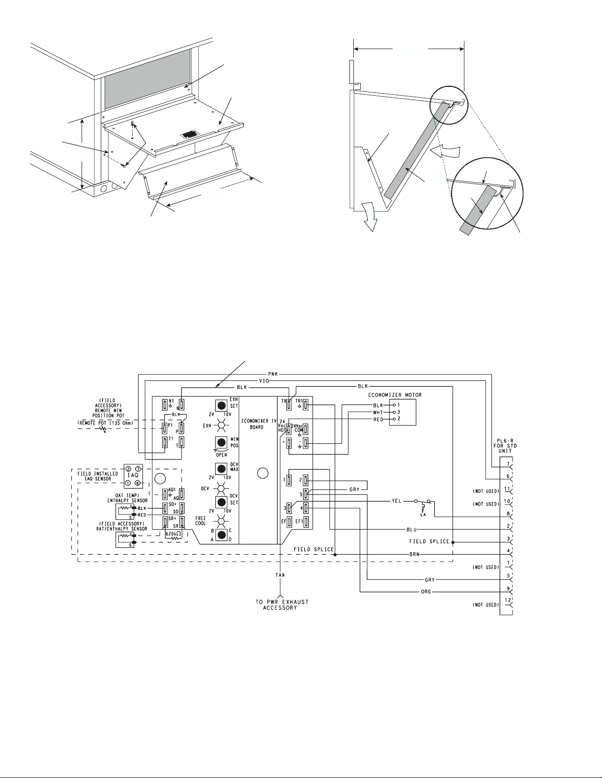
B. Optional EconoMi$er IV
See Fig. 16 for EconoMi$er IV component locations.
NOTE: These instructions are for installing the optional
EconoMi$er IV only. Refer to the accessory EconoM i$er IV
installation instructions when field installing an
EconoMi$er IV accessory.
1. To remove the existing unit filter access panel, raise
the panel and swing the bottom outward. The panel is
now disengaged from the track and can be removed.
See Fig. 17.
2. The box with the economizer hood components is
shipped in the compartment behind the economizer.
The EconoMi$er IV controller is mounted on top of
the EconoMi$er I V in the position shown in Fig. 16.
The optional EconoMi$er2 with 4 to 20 mA actuator
signal control does not include the EconoMi$er IV
controller. To remove the component box from its
shipping position, remove the screw holding the hood
box bracket to the top of the economizer. Slide the
hood box out of the unit. See Fig. 18.
IMPORTANT: If the power exhaust accessory is to be
installed on the unit, the hood shipped with the unit will not
be used and must be discarded. Save the aluminum filter
for use in the power exhaust hood assembly.
3. The indoor coil access panel will be used as the top of
the hood. Remove the screws along the sides an d bottom of the indoor coil access panel. See Fig. 19.
4. Swing out indoor coil access panel and insert the
hood sides under the panel (hood top). Use the screws
provided to attach the hood sides to the hood top. Use
screws provided to attach the hoo d sides to the unit.
See Fig. 20.
5. Remove the shipping tape holding the economizer
barometric relief damper in place.
6. Insert the ho od divider between the hood s ides. See
Fig. 20 and 21. Secure hood divider with 2 screws on
each hood side. The hood divider is also used as the
bottom filter rack for the aluminum filter.
7. Open the filter clips which are located underneath
the hood top. Insert the aluminum filter into the bottom filter rack (hood divider). Push the filter into position past the op en filter clips. Close the fi lter clips
to lock the filter into place. See Fig. 21.
8. Caulk the ends of the joint between the unit top panel
and the hood top. See Fig. 19.
9. Replace the filter access panel.
10. Install all EconoMi$er IV accessories. EconoMi$er IV
wiring is shown in Fig. 22.
Barometric flow capacity is shown in Fig. 23. Outdoor air
leakage is shown in Fig. 24. Return air pressure drop is
shown in Fig. 25.
x
o
B
H
d
o
o
HOOD BOX
BRACKET
ECONOMI$ER IV
CONTROLLER
WIRING
HARNESS
ACTUATOR
OUTSIDE AIR
TEMPERATURE SENSOR
LOW AMBIENT
SENSOR
Fig. 16 — EconoMi$er IV Component Locations
FILTER ACCESS PANEL
COMPRESSOR
ACCESS PANEL
OUTDOOR-AIR OPENING AND
INDOOR COIL ACCESS PANEL
Fig. 17 — Typical Access Panel Locations
Fig. 18 — Hood Box Removal
SIDE
PANEL
TOP
SIDE
PANEL
INDOOR
COIL
ACCESS
PANEL
INDOOR
COIL
ACCESS
PANEL
CAULK
HERE
Fig. 19 — Indoor Coil Access Panel Relocation
—15—
Page 16
TOP
PANEL
INDOOR COIL
ACCESS PANEL
17 1/4”
LEFT
HOOD
SIDE
B
19 1/16”
HOOD DIVIDER
SCREW
Fig. 20 — Outdoor-Air Hood Construction
33 3/8”
BAROMETRIC
RELIEF
FOR OCCUPANCY CONTROL
REPLACE JUMPER WITH
FIELD-SUPPLIED TIME CLOCK
DIVIDER
OUTSIDE
AIR
CLEANABLE
ALUMINUM
FILTER
FILTER
Fig. 21 — Filter Installation
HOOD
FILTER
CLIP
LEGEND
DCV — Demand Controlled Ventilation
IAQ — Indoor Air Quality
LA — Low Ambient Lockout Device
OAT — Outdoor-Air Temperature
POT — Potentiometer
RAT — Return-Air Temperature
Potentiometer Defaults Settings:
Power Exhaust Middle
Minimum Pos. Fully Closed
DCV Max. Middle
DCV Set Middle
Enthalpy C Setting
Fig. 22 — EconoMi$er IV Wiring
NOTES:
1. 620 ohm, 1 watt 5% resistor should be removed only when using differential
enthalpy or dry bulb.
2. If a separate field-supplied 24 v transformer is used for the IAQ sensor power
supply, it cannot have the secondary of the transformer grounded.
3. For field-installed remote minimum position POT, remove black wire jumper
between P and P1 and set control minimum position POT to the minimum
position.
—16—
Page 17

2500
2000
1500
1000
500
0
FLOW IN CUBIC FEET PER MINUTE (cfm)
0.05
STATIC PRESSURE (in. wg)
0.15
Fig. 23 — Barometric Flow Capacity
30
25
20
15
10
5
0
0.13 0.2 0 0.22 0. 25 0.30 0.35 0 .40 0 .45 0.50
FLOW IN CUBIC FEET PER MINUTE (cfm)
STATIC PRESSURE (in. wg)
Fig. 24 — Outdoor-Air Damper Leakage
0.25
Outdoor Air Lockout Sensor
The EconoMi$er I V is equipped with an ambi ent tempera-
ture lockout switch located i n the outdoor air stream which
is used to lockout the co mpresso rs belo w a 42 F ambie nt te mperature. See Fig. 16.
Table 3 — Supply Air Sensor
Temperature/Resistance Values
TEMPERATURE (F) RESISTANCE (ohms)
–58 200,250
–40 100,680
–22 53,010
–4 29,091
14 16,590
32 9,795
50 5,970
68 3,747
77 3,000
86 2,416
104 1,597
122 1,080
140 746
158 525
176 376
185 321
194 274
212 203
230 153
248 116
257 102
266 89
284 70
302 55
6000
5000
4000
3000
2000
1000
0
0.05 0.10 0.15 0. 20 0.25 0.30 0. 35
FLOW IN CUBIC FEET PER MINUTE (cfm)
STATIC PRESSURE (in. wg)
Fig. 25 — Return-Air Pressure Drop
C. EconoMi$er IV Standard Sensors
Outdoor Air Temperature (OAT) Sensor
The outdoor air temperature sensor (HH57AC074) is a 10 to
20 mA device used to measure the outdoo r-air temperature.
The outdoor-air temperature is used to determine when
the EconoMi$ er IV ca n be used for free cooling. The sensor is
factory-installed on the EconoMi$er IV in the outdoor
airstream. See Fig. 16. The ope rating range of temperatu re
measurement is 40 to 100 F.
Supply Air Temperature (SAT) Sensor
The supply air temperature sensor is a 3 K thermistor
located at the inlet of the indoor fan. See Fig. 26. This
sensor is factory installed. The operating range of temperature measurement is 0° to 158 F. See Table 3 for sensor
temperature/resistance values.
The temperature sensor l ooks like an eyelet terminal with
wires running to it. The sensor is located in the “crimp end”
and is sealed from moisture.
D. EconoMi$er IV Control Modes
Determine the EconoMi$er IV control mode before set up of the
control. Some modes of operation may require different sensors.
Refer to Table 4. The EconoMi$er IV is supplied fr om the f actory with a supply air temperature sensor and an outdoor air
temperature sensor. This allows for operation of the
EconoMi$er IV with outdoor air dry bulb changeover control.
Additional accessories can be added to allow for different
types of changeover con tro l and op era ti on of the Econ oMi $e r
IV and unit.
Outdoor Dry Bulb Changeover
The standard controller is shippe d from the factory config-
ured for outdoor dry bulb changeover control. The outdoor
air and supply air temperature sensors are included as
standard. For this control mode, the outdoor temperature is
compared to an adjustable set point selected on the control.
If the outdoor-air temperature is above the set point, the
EconoMi$er IV will adjust the outdoor air dampers to minimum position. If the outdoor-air temperature is below the set
point, the position of the outdoor air dampers will be
controlled to pr ovide fr ee cooli ng using o utdoor ai r. When in
this mode, the LED next to the free cooling set point potentiometer will be on. T he changeover temperat ure set point is
controlled by the free cooling set poi nt pote ntiometer locat ed
on the control. Se e Fig. 27. Th e s cale on the pote n tio me ter is
A, B, C, and D . See Fig. 28 for the corresponding temperature
changeover values.
Differential Dry Bulb Control
For differential dry bulb control the standard outdoor dry
bulb sensor is used in conjunction with an additional accessory dry bulb sensor (part number CRTEMPSN002A00). The
accessory senso r must be mounted in the return airstream.
See Fig. 29. Wiring is provided in th e EconoMi$e r IV wiring
harness. See Fig. 22.
—17—
Page 18

In this mode of operation, the outdoor air temperature is
compared to the return air temperature and the lower temperature air stream is used for cooling. When using this
mode of changeover control, turn the enthalpy setpoint
potentiometer fully clockwise to the D setting. See Fig. 27.
Outdoor Enthalpy Changeover
For enthalpy control, accessory enthalpy sensor (part num-
ber HH57AC078) is required. Replace the standard outdoor
dry bulb temperature sensor with the accessory enthalpy
sensor in the same mou nt ing lo ca tio n . Se e Fig. 16. When the
outdoor air enthalpy rises above the outdoor enthalpy
changeover set point, the outdoor-air damper moves to its
minimum position. The outdoor enthalpy changeover set
point is set with the outdoo r enthalpy set point potentiometer on the EconoMi$er IV controller. The set points are A, B,
C, and D. See Fig. 30. The factory-installed 620-ohm jumper
must be in place across terminals SR and SR+ on the
EconoMi$er IV controller. See Fig. 16 and 31.
Differential Enthalpy Control
For differential enthalpy control, the EconoMi$er IV con-
troller uses two enthalpy sensors (HH57AC078 and
CRENTDIF004A00), one in the outside air and one in the
return air duct. The EconoMi$er IV controller compares the
outdoor air enthalpy to the return air enthalpy to determine
EconoMi$er IV use. The contro ll er selects the lowe r en thalpy
air (return or outdoor) for cooling. For example, when the
outdoor air has a lower enthalpy than the return air, the
EconoMi$er IV opens to b r ing in outdoor air for free cooling.
19
LED ON
18
17
16
15
mA
14
13
12
11
10
9
40
LED OFF
45
D
50
60
55
DEGREES FAHRENHEIT
LED ON
C
LED OFF
65
70
LED ON
LED OFF
75
Fig. 28 — Outdoor Air Temperature
Changeover Set Points
ECONOMI$ER IV
B
85
80
ECONOMI$ER IV
CONTROLLER
RETURN AIR
SENSOR
LED ON
LED OFF
90
A
100
95
GROMMET
SUPPLY AIR
TEMPERATURE
SENSOR
MOUNTING
LOCATION
SUPPLY AIR
TEMPERATURE
SENSOR
Fig. 26 — Supply Air Sensor Location
Fig. 27 — EconoMi$er IV Controller Potentiometer
and LED Locations
RETURN DUCT
(FIELD-PROVIDED)
Fig. 29 — Return Air Temperature or Enthalpy
Sensor Mounting Location
Replace the standard outside air d ry bulb temperatu re sensor
with the accessory enthalpy sensor in the same mounting location. See Fig. 16. Mount the return air enthalpy sensor in the
return air duct. See Fig. 29. Wiring is provided in the
EconoMi$er IV wiring harness. See Fig. 22. The outdoor
enthalpy changeover set point is set with the outdoor enthalpy
set point potentiometer on the EconoMi$er IV controller. When
using this mode of chan geover control, turn the enthalpy s et
point potentiometer fully clockwise to the D setting.
Table 4 — EconoMi$er IV Sensor Usage
ECONOMI$ER IV WITH OUTDOOR AIR
APPLICATION
Outdoor Air
Dry Bulb
Differential
Dry Bulb
Single Enthalpy HH57AC078
Differential
Enthalpy
CO
for DCV
2
Control using a
Wall-Mounted
CO
Sensor
2
CO
for DCV
2
Control using a
Duct-Mounted
CO
Sensor
2
*CRENTDIF004A00 and CRTEMPSN002A00 accessories are used on many
different base units. As such, these kits may contain parts that will not be
needed for installation.
†33ZCSENCO2 is an accessory CO
**33ZCASPCO2 is an accessory aspirator box required for duct-mounted
applications.
††CRCBDIOX005A00 is an accessory that contains both 33ZCSENCO2 and
33ZCASPCO2 accessories.
33ZCSENCO2†
33ZCASPCO2**
DRY BULB SENSOR
Accessories Required
None. The outdoor air dry bulb sensor
is factory installed.
CRTEMPSN002A00*
HH57AC078
and
CRENTDIF004A00*
33ZCSENCO2
and
sensor.
2
CRCBDIOX005A00††
OR
—18—
Page 19

CONTROL
CURVE
4
1
2
1
A
B
C
D
1
6
1
CONTROL POINT
APPROX. °F (°C)
AT 50% RH
73 (23)
70 (21)
67 (19)
63 (17)
HA
NT
E
4
2
2
2
0
2
8
35
(2)
LPY
40
(4)
85
(29)90(32)95(35)
46
4
4
42
40
IR
8
3
Y A
6
DR
3
D
N
U
4
3
PO
R
32
E
P
TU
30
B
—
28
26
(16)
55
(13)
B
50
C
(10)
45
D
(7)
70
(21)
0
1
65
(18)
60
A
80
(27)
75
(24)
0
0
9
80
70
0
6
50
40
3
RELA
0
IVE HUM
T
100
(38)
IDITY
20
105
110
(41)
(43)
)
%
(
0
1
35
40
45
50
55
60
65
(2)
(4)
(7)
(10)
(13)
(16)
(18)
(21)
70
APPROXIMATE DRY BULB TEMPERATURE— °F (°C)
Fig. 30 — Enthalpy Changeover Settings
TR1
N1
P1
T1
AQ1
SO+
SR+
EXH
2V 10V
EXH
Open
2V 10V
DCV
2V 10V
Free
Cool
B
A
Min
Pos
DCV
Max
DCV
C
D
Set
Set
N
P
T
AQ
SO
SR
TR
24
24 Vac
Vac
COM
HOT
_
+
12
5
4
3
EF1
EF
Fig. 31 — EconoMi$er IV Control
Indoor Air Quality (IAQ) Sensor Input
The IAQ input can be used for demand control ventilation
control based on the level of CO
measured in the spa ce or
2
return air duct.
Mount the accessory IAQ sensor according to manufacturer
specifications. The IAQ sensor should be wired to the AQ and
AQ1 terminals of the controller. Adjust the DCV potentiometers to correspond to the DCV voltage output of the indoor air
quality sensor at the user-determined set point. See Fig. 32.
A
B
C
D
75
(24)
80
(27)
(29)90(32)95(35)
105
85
100
(38)
(41)
110
(43)
HIGH LIMIT
CURVE
If a separate field-supplied transformer is used to power the
IAQ sensor, the sensor must not be grounded or the
EconoMi$er IV control board will be damaged.
Exhaust Set Point Adjustment
The exhaust set point will determine when the exhaust fan
runs based on d am p er p o sit i on ( if ac ce ss or y pow e r ex ha ust i s
installed). The set point is modified with the Exhaust Fan
Set Point (EXH SET) potentiometer. See Fig. 27. The set
point represents the damper position above which the
exhaust fans will be turned on. When there is a call for
exhaust, the EconoMi$er IV controller provides a 45 ± 15
second delay before exhaust fan activation to allow the
dampers to open. This delay allows the damper to reach the
appropriate position to avoid unnecessary fan overload.
Minimum Position C o ntrol
There is a minimum damper position potentiometer on the
EconoMi$er IV c o nt ro ll er. See Fig. 27. The mini mum damper
position maintains the minimum airflow into the building
during the occupied period.
When using demand ventilation, the minimum damper position represents the minimum ventilation position for VOC
(volatile organic compound) ventilation requirements. The
maximum demand ventilation position is used for fully occupied ventilation.
When demand ventilation control is not being used, the minimum position potentiometer should be used to set the occupied ventilation position. The maximum demand ventilation
position should be turned fully clock wi se.
Adjust the minimum position potentiometer to allow the
minimum amount of outdoor air, as required by local codes,
—19—
Page 20

CO SENSOR MAX RANGE SETTING
2
6000
5000
4000
3000
2000
1000
RANGE CONFIGURATION (ppm)
0
2345678
DAMPER VOLTAGE FOR MAX VENTILATION RATE
800 ppm
900 ppm
1000 ppm
1100 ppm
Fig. 32 — CO2 Sensor Maximum Range Setting
to enter the building. Make minimum position adjustments
with at least 10 F temperature difference between the outdoor and return-air temperatures.
To determine the minimum position setting, perform the
following proced ur e :
1. Calculate the appropriate mixed air temperature
using the following formula:
OA
(T
x
)+ (TR x
100 100
= Outdoor-Air Temperature
T
O
O
RA
) = T
M
OA = Percent of Outdoor Air
TR = Return-Air Temperature
RA = Percent of Return Air
TM = Mixed-Air Temperature
As an example, if local codes require 10% outdoor air
during occupied conditions, outdoor-air temperature
is 60 F, and return-air temperature is 75 F.
(60 x .10) + (75 x .90) = 73.5 F
2. Disconnect the supply air sensor from terminals T
and T1.
3. Ensure that the factory-installed jumper is in place
across terminals P and P1. If remote damper positioning is being used, make sure that the terminals
are wired accor din g to Fig. 22 and that t he mi nimu m
position potentiometer is turned fully clockwise.
4. Connect 24 vac across terminals TR and TR1.
5. Carefully adjust th e minim um positi on potent iomet er
until the measured mixed-air temperature matches
the calculated va lue.
6. Reconnect the supply air sensor to terminals T and
T1.
Remote control of the EconoMi$er IV damper is desirable
when requiring additional temporary ventilation. If a
field-supplied remote potentiometer (Honeywell part number S963B1128) is wired to the E co no Mi$er IV controller, th e
minimum position of the damper can be controlled from a
remote location.
To control the minimum damper position remotely, remove
the factory-insta lled jumper on the P and P1 terminals on
the EconoMi$er IV controller. Wire the field-supplied potentiometer to the P and P1 termina ls on the EconoMi$er IV
controller. See Fig. 31.
Damper Movement
Damper movement from full open to full closed (or vice
versa) takes 2
1
/2 minutes.
Thermostats
The EconoMi$er IV control works with conventional thermo-
stats that have a Y1 (cool stage 1), Y2 (cool stage 2), W1
(heat stage 1), W2 (heat stage 2), and G (fan). The
EconoMi$er IV control do es not support space temperature
sensors. Connections are made at the thermostat terminal
connection board located in the main control box.
Occupancy Control
The factory default configuration for the Econo Mi$er IV con -
trol is occupied mode. Occupied status is provided by the
black jumper from terminal TR to terminal N. When unoccupied mode is desired, install a field-supplied timeclock function in place of th e jumper between TR an d N. See Fig. 22.
When the timeclock contacts are closed, the EconoMi$er I V
control will be in occupied mode. When the timeclock contacts are open (removin g the 24-v signal from terminal N),
the EconoMi$er IV will be in unoccupied mode.
Demand Controlled V enti lation (DCV)
When using the EconoMi$er IV for demand controlled venti-
lation, there are some equipment selection criteria which
should be considered. When selecting the heat capacity and
cool capacity of the equipment, the maximum ventilation
rate must be evaluated for design conditio ns. The maximum
damper position must be calculated to provide the desired
fresh air.
Typically the maximum ventilation rate will be ab out 5 to
10% more than the typical cfm required per person, using
normal outside air design criteria.
A proportional anticipatory strategy should be taken with
the following conditions: a zone with a large area, varied
occupancy, and equipm ent that cannot exceed the req uired
ventilation rate at design con dition s. Exceeding th e requ ired
ventilation rate means the equipment can co ndition air a t a
maximum ventilation rate that is gre ater than the requ ired
ventilation rate for maximum occupancy. A proportionalanticipatory strategy will cause the fresh air supplied to
increase as the room CO
level increases even though the
2
CO2 set point has not been reached. By the time the CO
level reaches the set point, the damper will be at maximum
ventilation and should maintain the set point.
In order to have the CO
sensor control the economizer
2
damper in this manner, first determine the damper voltage
output for minimum or base ventilat ion. Base v entilatio n is
the ventilation required to remove contaminants during
unoccupied periods. The following equation may be used to
determine the percent of outside-air entering the building for
a given damper position. For best results there should be at
least a 10 degree difference in outside and return-air
temperatures.
OA
(TO x
T
O
)+ (TR x
100 100
= Outdoor-Air Temperature
RA
) = T
M
OA = Percent of Outdoor Air
TR = Return-Air Temperature
RA = Percent of Return Air
TM = Mixed-Air Temperature
Once base ventilation has been determined, set the mini-
mum damper position potentiometer to the correct position.
The same equation can be used to determine the occupied or
maximum ventilation rate to the building. For example, an
2
—20—
Page 21

output of 3.6 volts t o the ac tuat o r pro vide s a ba se ve ntil at io n
rate of 5% and an output of 6.7 volts provides the maximum
ventilation rate of 20% (or bas e plu s 15 cfm pe r pers on). Use
Fig. 32 to determine the maximum setting of the CO
sensor.
2
For example, a 1100 ppm set point relates to a 15 cfm per
person design. Use the 1100 ppm curve on Fig. 32 to find the
point when the CO
sensor output will be 6.7 volts. Line up
2
the point on the graph with the left side of the chart to determine that the range configuration for the CO
sensor should
2
be 1800 ppm. The EconoMi$er IV controller will output the
6.7 volts f rom th e CO
sensor to the actuator when the CO
2
concentration in the spac e is a t 1100 ppm . The D CV set point
may be left at 2 volts since the CO
sensor voltage will be
2
ignored by the Econ oMi$er IV co ntroller u ntil it rises above
the 3.6 volt setting of the minimum position potentiometer.
Once the fully occupied damper position has been determined, set the maximu m da mpe r de ma nd con t ro l ve nt il atio n
potentiometer to this position. Do not set to the maximum
position as this can result in over-ventilation to the space
and potential high-humidity levels.
CO
Sensor Configuration
2
The CO2 sensor has preset standard voltage settings that
can be selected anytime afte r the sensor is powere d up. See
Table 5.
Use setting 1 or 2 f or Bryant equipment. See Table 5.
1. Press Clear and Mode buttons. Hold at least 5 seconds until the sensor enters the Edit mode.
2. Press Mode twice. The STDSET Menu will appear.
3. Use the Up/Down button to select the preset number.
See Table 5.
4. Press Enter to lock in the selection.
5. Press Mode to exit and resume normal operation.
The custom settings of the CO
sensor can be changed any-
2
time after the s ensor is energiz ed. Follow the s teps belo w to
change the non-standard settings:
1. Press Clear and Mode buttons. Hold at least 5 seconds until the sensor enters the Edit mode.
2. Press Mode twice. The STDSET Menu will appear.
2
3. Use the Up/Down button to toggle to the NONSTD
menu and press Enter.
4. Use the Up/Down button to toggle through each of
the nine variables, starting with Altitude, until the
desired setting is reached.
5. Press Mode to move through the variables.
6. Press Enter to lock in the selection, then press Mode
to continue to the next variable.
Dehumidification of Fresh Air with DCV Control
Information from ASHRAE indicates that the largest humid-
ity load on any zone is the fresh air introduced. For some
applications, an energy recove ry unit is added t o reduce the
moisture content of the fresh air being brought into the
building when the enthalpy is hi gh. In most cases, the no rmal heating and co oling proc esse s are m ore tha n ade quate to
remove the humidity loads for most commercial applications.
If normal roof top heating and cooling operation is not adequate for the outdoor humidity level, an energy recovery unit
and/or a dehumidification option should be con sidered.
Table 5 — C O
SETTING EQUIPMENT OUTPUT
1
Interface w/Standard
2 Proportional Any
Building Control System
3 Exponential Any
4
5 Proportional 20
Economizer
6 Exponential 15
7 Exponential 20
8 Health & Safety Proportional —
Parking/Air Intakes/
9
Loading Docks
LEGEND
ppm — Parts Per Million
Proportional Any
Proportional 15
Proportional —
Sensor Standard Settings
2
VENTILATION
RATE
(cfm/Person)
ANALOG
OUTPUT
0-10V
4-20 mA
2-10V
7-20 mA
0-10V
4-20 mA
0-10V
4-20 mA
0-10V
4-20 mA
0-10V
4-20 mA
0-10V
4-20 mA
0-10V
4-20 mA
0-10V
4-20 mA
CO
CONTROL RANGE
2
(ppm)
0-2000 1000 50
0-2000 1000 50
0-2000 1100 50
0-1100 1100 50
0- 900 900 50
0-1100 1100 50
0- 900 900 50
0-9999 5000 500
0-2000 700 50
OPTIONAL
RELAY SETPOINT
(ppm)
RELAY
HYSTERESIS
(ppm)
—21—
Page 22

IX. STEP 9 — ADJUST EVAPORATOR-FAN SPEED
Adjust evaporator-fan speed to meet jobsite requirements.
Table 6 shows fan rpm at motor pulley settings. Table 7
shows motor performance. Table 8 provides accessory static
pressure drop information. Refer to Tables 9-32 to determine
fan speed settings.
A. Direct-Drive Motors
The evaporator-fan motor factory speed setting is shown on
label diagram affixed to base unit. If other than factory setting is desired, refer to label diagram for motor reconnection.
See Fig. 33 for direct drive motor location.
B. Belt-Drive Motors
Fan motor pulleys are factory set for speed shown in Table 1.
See Fig. 34 for belt drive motor location.
NOTE: Before adjusting fan speed, make sure the new fan
speed will provi de an air temperature rise range as sho w n in
Table 1.
To change fan speed:
1. Shut off unit power supply and tag disconnect.
2. Loosen belt by loosening fan motor mounting nuts.
See Fig. 34.
3. Loosen movable pulley flange setscrew (see Fig. 35).
4. Screw movable flange toward fixed flange to increase
speed and away from fixed flange to decrease speed.
Increasing fan speed incr eases lo ad on motor. Do not
exceed maximum speed specified in Table 1.
5. Set movable flange at nearest keyway of pulley hub
and tighten setscrew. (See Table 1 for speed change
for each full turn of pulley flange.)
To align fan and motor pulleys:
1. Loosen fan pulley setscrews.
2. Slide fan pulley along fan shaft.
3. Make angular alignment by loosening motor from
mounting.
To adjust belt tension:
1. Loosen fan motor mounting nuts.
2. Slide m otor mounting plate away from fa n scroll fo r
proper belt tension (
1
/2-in. deflection with 8 to 10 lb of
force).
3. Tighten motor mounting nuts.
4. Adjust bolt and tighten nut to secure motor in fixed
position.
MOTOR MOUNTING
PLATE NUTS
Fig. 34 — Belt Drive Motor Mounting
Fig. 33 — Direct-Drive Motor Mounting
Fig. 35 — Evaporator-Fan Pulley Adjustment
—22—
Page 23

Table 6 — Fan Rpm at Motor Pulley Settings*
UNIT
580F
0
036† 1045 1009 973 937 901 865 829 793 757 721 685 — —
1
/
2
11
1
/
2
036** 1455 1423 1392 1360 1328 1297 1265 1233 1202 1170 1138 1107 1075
048† 1175 1135 1094 1054 1013 973 932 892 851 811 770 — —
048** 1455 1423 1392 1360 1328 1297 1265 1233 1202 1170 1138 1107 1075
060† 1192 1166 1140 1114 1087 1061 1035 1009 983 957 930 904 878
060** 1685 1647 1608 1570 1531 1493 1454 1416 1377 1339 1300 — —
072, 073†† 1460 1421 1382 1343 1304 1265 1226 1187 1148 1109 1070 — —
072, 073** 1685 1647 1608 1570 1531 1493 1454 1416 1377 1339 1300 — —
*Approximate fan rpm shown.
†Indicates alternate motor and drive package.
MOTOR PULLEY TURNS OPEN
22
1
/
††Indicates standard motor and drive package.
33
2
**Indicates high-static motor and drive package.
1
/
2
44
1
/
2
55
Table 7 — Motor Data
UNIT
580F
036
048
060
072, 073
LEGEND
BHP — Brake Horsepower
*Extensive motor and electrical testing on these units ensures that the full horse-
power range of the motors can be utilized with confidence. Using fan motors up
to the horsepower ratings shown in this table will not result in nuisance tripping
or premature motor failure. Unit warranty will not be affected.
†Single phase/three-phase.
EVAPORATOR-FAN
MOTOR
Standard
Alternate
High Static
Standard
Alternate
High Static
Standard
Alternate
High Static
Standard
High Static
UNIT
VOLTAGE
MAXIMUM ACCEPTABLE
CONTINUOUS BHP*
MAXIMUM ACCEPTABLE
OPERATING WATTS
208/230
460 1.3
0.34 440
575 1.3
208/230
460 2.1
1.20 1000
575 2.1
208/230
460 3.0
2.40 2120
575 3.0
208/230
460 1.8
0.75 850
575 1.8
208/230
460 2.1
1.20 1000
575 2.1
208/230
460 3.0
2.40 2120
575 3.0
208/230
460 3.2
1.20 1340
575 3.2
208/230
460 3.0
1.30/2.40† 2120
575 3.0
208/230
460 3.9
2.90 2562
575 3.9
208/230
460 3.0
2.40 2120
575 3.0
208/230
460 3.9
2.90 2562
575 3.9
NOTES:
1. All indoor-fan motors 5 hp and larger meet the minimum efficiency requirements as established by the Energy Policy Act of 1992 (EPACT) effective
October 24, 1997.
2. High-static motor not available on single-phase units.
1
/
2
MAXIMUM
AMP DRAW
2.8
4.9
6.0
3.5
4.9
6.0
5.9
10.1/6.7†
8.6
6.7
8.6
6
COMPONENT
Vertical EconoMi$er IV
Horizontal EconoMi$er IV
LEGEND
FIOP — Factory-Installed Option
Table 8 — Accessory/FIOP Static Pressure* (in. wg)
2250 2500 3000 3500 4000 4500 5000
0.06 0.075 0.115 0.15 0.195 0.25 0.325
— 0.10 0.15 0.21 0.275 0.34 —
*The static pressure must be added to external static pressure. The sum and the
evaporator entering-air cfm should then be used in conjunction with the Fan
Performance tables to determine blower rpm and watts.
CFM
—23—
Page 24

Table 9 — Fan Performance 580F036 — Vertical Discharge Units, Standard Motor
Airflow
(Cfm)
900 0.49 0.21 253 0.50 0.23 277 0.51 0.26 307 0.55 0.31 363
1000 0.42 0.23 270 0.43 0.25 292 0.43 0.27 321 0.51 0.32 374
1100 0.37 0.24 287 0.38 0.26 307 0.39 0.28 335 0.46 0.33 385
1200 0.33 0.26 304 0.33 0.27 323 0.34 0.29 349 0.40 0.34 397
1300 0.27 0.27 321 0.28 0.29 338 0.28 0.31 364 0.34 0.34 408
1400 0.20 0.29 338 0.23 0.30 354 0.25 0.32 378 — — —
1500 0.16 0.30 355 0.18 0.31 369 0.20 0.33 392 — — —
LEGEND See page 34 for general fan performance notes.
Bhp — Brake Horsepower Input to Fan
ESP — External Static Pressure (in. wg)
ESP Bhp Watts ESP Bhp Watts ESP Bhp Watts ESP Bhp Watts
208 V 230, 460, 575 V 208 V 230, 460, 575 V
Low Speed High Speed
STANDARD MOTOR (DIRECT DRIVE)
Table 10 — Fan Performance 580F036 — Vertical Discharge Units, Alternate Motor (Belt Drive)*
AIRFLOW
(Cfm)
900 643 0.15 152 768 0.22 222 870 0.30 296 958 0.37 373 1037 0.46 454
1000 683 0.19 191 804 0.27 268 904 0.35 348 991 0.43 430 1069 0.52 517
1100 725 0.24 237 842 0.32 321 939 0.41 407 1025 0.50 496 1102 0.59 588
1200 767 0.29 291 880 0.38 382 976 0.48 474 1060 0.57 570 1136 0.67 668
1300 811 0.35 352 920 0.45 451 1013 0.55 550 1095 0.66 652 1170 0.76 756
1400 855 0.43 423 960 0.53 529 1051 0.64 636 1132 0.75 744 1205 0.86 855
1500 900 0.51 504 1002 0.62 617 1090 0.74 731 1169 0.85 846 1242 0.97 963
AIRFLOW
(Cfm)
900 1110 0.54 538 1177 0.63 627 1239 0.72 718 1298 0.82 813 1355 0.92 911
1000 1141 0.61 607 1207 0.70 700 1269 0.80 796 1328 0.90 895 1384 1.00 998
1100 1173 0.69 683 1238 0.79 781 1300 0.89 883 1358 0.99 987 1414 1.10 1094
1200 1205 0.77 768 1270 0.88 872 1332 0.98 979 1389 1.09 1088 —— —
1300 1239 0.87 863 1303 0.98 972 1364 1.09 1084 —— — —— —
1400 1273 0.97 967 1337 1.09 1082 —— — —— — —— —
1500 1309 1.09 1082 —— — —— — —— — —— —
Rpm Bhp Watts Rpm Bhp Watts Rpm Bhp Watts Rpm Bhp Watts Rpm Bhp Watts
Rpm Bhp Watts Rpm Bhp Watts Rpm Bhp Watts Rpm Bhp Watts Rpm Bhp Watts
0.2 0.4 0.6 0.8 1.0
1.2 1.4 1.6 1.8 2.0
LEGEND
Bhp — Brake Horsepower Input to Fan
Watts — Input Watts to Motor
*Motor drive range: 685 to 1045 rpm. All other rpms require a field-
supplied drive.
EXTERNAL STATIC PRESSURE (in. wg)
EXTERNAL STATIC PRESSURE (in. wg)
NOTES:
1. Boldface indicates field-supplied drive is required.
2. Maximum continuous bhp is 1.20.
3. See page 34 for general fan performance notes.
Table 11 — Fan Performance 580F036 — Vertical Discharge Units, High-Static Motor (Belt Drive)*
AIRFLOW
(Cfm)
900 643 0.15 152 768 0.22 222 870 0.30 296 958 0.37 373 1037 0.46 454
1000 683 0.19 191 804 0.27 268 904 0.35 348 991 0.43 430 1069 0.52 517
1100 725 0.24 237 842 0.32 321 939 0.41 407 1025 0.50 496 1102 0.59 588
1200 767 0.29 291 880 0.38 382 976 0.48 474 1060 0.57 570 1136 0.67 668
1300 811 0.35 352 920 0.45 451 1013 0.55 550 1095 0.66 652 1170 0.76 756
1400 855 0.43 423 960 0.53 529 1051 0.64 636 1132 0.75 744 1205 0.86 855
1500 900 0.51 504 1002 0.62 617 1090 0.74 731 1169 0.85 846 1242 0.97 963
AIRFLOW
(Cfm)
900 1110 0.54 538 1177 0.63 627 1239 0.72 718 1298 0.82 813 1355 0.92 911
1000 1141 0.61 607 1207 0.70 700 1269 0.80 796 1328 0.90 895 1384 1.00 998
1100 1173 0.69 683 1238 0.79 781 1300 0.89 883 1358 0.99 987 1414 1.10 1094
1200 1205 0.77 768 1270 0.88 872 1332 0.98 979 1389 1.09 1088 1444 1.21 1200
1300 1239 0.87 863 1303 0.98 972 1364 1.09 1084 1421 1.21 1199 1475 1.32 1316
1400 1273 0.97 967 1337 1.09 1082 1397 1.21 1200 1453 1.33 1320 1507 1.45 1443
1500 1309 1.09 1082 1371 1.21 1204 1430 1.33 1327 1486 1.46 1453 1540 1.59 1581
Rpm Bhp Watts Rpm Bhp Watts Rpm Bhp Watts Rpm Bhp Watts Rpm Bhp Watts
Rpm Bhp Watts Rpm Bhp Watts Rpm Bhp Watts Rpm Bhp Watts Rpm Bhp Watts
0.2 0.4 0.6 0.8 1.0
1.2 1.4 1.6 1.8 2.0
LEGEND
Bhp — Brake Horsepower Input to Fan
Watts — Input Watts to Motor
*Motor drive range: 1075 to 1455 rpm. All other rpms require a field-supplied
drive.
EXTERNAL STATIC PRESSURE (in. wg)
EXTERNAL STATIC PRESSURE (in. wg)
NOTES:
1. Boldface indicates field-supplied drive is required.
2. Maximum continuous bhp is 2.40.
3. See page 34 for general fan performance notes.
—24—
Page 25

Table 12 — Fan Performance 580F048 — Vertical Discharge Units, Standard Motor
Airflow
(Cfm)
1200 0.68 0.41 458 0.74 0.45 506 0.74 0.51 572 0.85 0.56 632
1300 0.61 0.42 471 0.67 0.46 521 0.66 0.52 589 0.78 0.58 651
1400 0.53 0.45 503 0.59 0.49 556 0.59 0.54 616 0.70 0.60 681
1500 0.45 0.47 536 0.51 0.52 593 0.52 0.56 631 0.63 0.62 698
1600 0.36 0.49 557 0.42 0.54 616 0.45 0.58 654 0.56 0.64 723
1700 0.26 0.52 584 0.32 0.57 646 0.37 0.60 678 0.48 0.66 750
1800 0.15 0.54 610 0.22 0.60 674 0.30 0.62 698 0.41 0.68 772
1900 0.04 0.56 629 0.11 0.62 696 0.23 0.64 720 0.34 0.70 796
2000 — — — — — — 0.16 0.66 744 0.26 0.73 823
ESP Bhp Watts ESP Bhp Watts ESP Bhp Watts ESP Bhp Watts
208 V 230, 460, 575 V 208 V 230, 460, 575 V
Low Speed High Speed
LEGEND See page 34 for general fan performance notes.
Bhp — Brake Horsepower Input to Fan
ESP — External Static Pressure (in. wg)
STANDARD MOTOR (DIRECT DRIVE)
Table 13 — Fan Performance 580F048 — Vertical Discharge Units, Alternate Motor (Belt Drive)*
AIRFLOW
(Cfm)
1200 666 0.26 257 778 0.37 367 871 0.47 471 952 0.57 572 1025 0.67 670
1300 701 0.31 306 810 0.43 426 901 0.54 540 981 0.65 651 1053 0.76 760
1400 737 0.36 361 842 0.49 491 931 0.62 616 1010 0.74 738 1081 0.86 856
1500 773 0.42 422 875 0.57 564 963 0.70 699 1040 0.84 831 1110 0.96 960
1600 810 0.49 491 909 0.65 643 994 0.79 790 1070 0.94 932 1140 1.08 1070
1700 847 0.57 567 943 0.73 730 1027 0.89 888 1101 1.05 1040 1170 1.20 1189
1800 885 0.66 652 978 0.83 826 1060 1.00 994 1133 1.16 1157 — — —
1900 923 0.75 745 1014 0.94 930 1093 1.11 1109 — — — — — —
2000 962 0.85 847 1049 1.05 1043 — — — — — — — — —
AIRFLOW
(Cfm)
1200 1093 0.77 767 1155 0.87 861 1213 0.96 955 1268 1.05 1047 1321 1.14 1137
1300 1119 0.87 866 1181 0.98 970 1239 1.08 1073 1294 1.18 1175 —— —
1400 1147 0.98 972 1208 1.09 1086 —— — —— — —— —
1500 1175 1.09 1086 — — — — — — — — — — — —
1600 —— — —— — —— — —— — —— —
1700 —— — —— — —— — —— — —— —
1800 —— — —— — —— — —— — —— —
1900 —— — —— — —— — —— — —— —
2000 —— — —— — —— — —— — —— —
Rpm Bhp Watts Rpm Bhp Watts Rpm Bhp Watts Rpm Bhp Watts Rpm Bhp Watts
Rpm Bhp Watts Rpm Bhp Watts Rpm Bhp Watts Rpm Bhp Watts Rpm Bhp Watts
0.20.40.60.81.0
1.21.41.61.82.0
LEGEND
Bhp — Brake Horsepower Input to Fan
Watts — Input Watts to Motor
*Motor drive range: 770 to 1175 rpm. All other rpms require a field-supplied drive.
EXTERNAL STATIC PRESSURE (in. wg)
EXTERNAL STATIC PRESSURE (in. wg)
NOTES:
1. Boldface indicates field-supplied drive is required.
2. Maximum continuous bhp is 1.20.
3. See page 34 for general fan performance notes.
Table 14 — Fan Performance 580F048 — Vertical Discharge Units, High-Static Motor (Belt Drive)*
AIRFLOW
(Cfm)
1200 666 0.26 257 778 0.37 367 871 0.47 471 952 0.57 572 1025 0.67 670
1300 701 0.31 306 810 0.43 426 901 0.54 540 981 0.65 651 1053 0.76 760
1400 737 0.36 361 842 0.49 491 931 0.62 616 1010 0.74 738 1081 0.86 856
1500 773 0.42 422 875 0.57 564 963 0.70 699 1040 0.84 831 1110 0.96 960
1600 810 0.49 491 909 0.65 643 994 0.79 790 1070 0.94 932 1140 1.08 1070
1700 847 0.57 567 943 0.73 730 1027 0.89 888 1101 1.05 1040 1170 1.20 1189
1800 885 0.66 652 978 0.83 826 1060 1.00 994 1133 1.16 1157 1200 1.32 1316
1900 923 0.75 745 1014 0.94 930 1093 1.11 1109 1165 1.29 1283 1231 1.46 1453
2000 962 0.85 847 1049 1.05 1043 1127 1.24 1233 1198 1.42 1417 1263 1.61 1598
AIRFLOW
(Cfm)
1200 1093 0.77 767 1155 0.87 861 1213 0.96 955 1268 1.05 1047 1321 1.14 1137
1300 1119 0.87 866 1181 0.98 970 1239 1.08 1073 1294 1.18 1175 1346 1.28 1275
1400 1147 0.98 972 1208 1.09 1086 1265 1.21 1199 1320 1.32 1310 1371 1.43 1419
1500 1175 1.09 1086 1235 1.22 1209 1292 1.34 1332 1346 1.46 1452 1397 1.58 1572
1600 1204 1.21 1207 1263 1.35 1340 1320 1.48 1472 1373 1.61 1603 1424 1.74 1732
1700 1233 1.34 1336 1292 1.49 1480 1348 1.63 1622 1401 1.77 1762 1451 1.91 1901
1800 1262 1.48 1473 1321 1.64 1627 1376 1.79 1779 1428 1.94 1930 1479 2.09 2078
1900 1293 1.63 1620 1350 1.79 1784 1405 1.96 1946 1457 2.12 2106 1506 2.28 2265
2000 1323 1.79 1776 1380 1.96 1950 1434 2.13 2123 1486 2.31 2293 —— —
Rpm Bhp Watts Rpm Bhp Watts Rpm Bhp Watts Rpm Bhp Watts Rpm Bhp Watts
Rpm Bhp Watts Rpm Bhp Watts Rpm Bhp Watts Rpm Bhp Watts Rpm Bhp Watts
0.20.40.60.81.0
1.21.41.61.82.0
LEGEND
Bhp — Brake Horsepower Input to Fan
Watts — Input Watts to Motor
*Motor drive range: 1075 to 1455 rpm. All other rpms require a field-supplied
drive.
EXTERNAL STATIC PRESSURE (in. wg)
EXTERNAL STATIC PRESSURE (in. wg)
NOTES:
1. Boldface indicates field-supplied drive is required.
2. Maximum continuous bhp is 2.40.
3. See page 34 for general fan performance notes.
—25—
Page 26

Table 15 — Fan Performance 580F060 — Vertical Discharge Units, Standard Motor
STANDARD MOTOR (DIRECT DRIVE)
Airflow
(Cfm)
1500 0.69 0.67 750 1.01 0.71 791 1.00 0.70 782 1.20 0.76 845 1.22 0.79 875 1.28 0.85 949
1600 0.49 0.70 780 0.85 0.74 824 0.85 0.74 821 1.06 0.79 883 1.09 0.82 913 1.17 0.89 988
1700 0.29 0.73 810 0.70 0.77 857 0.70 0.77 861 0.93 0.83 921 0.97 0.85 950 1.06 0.92 1027
1800 0.09 0.75 839 0.54 0.80 891 0.55 0.81 900 0.80 0.86 959 0.84 0.89 988 0.95 0.96 1066
1900 — — — 0.39 0.83 924 0.40 0.84 940 0.67 0.90 997 0.72 0.92 1025 0.84 0.99 1105
2000 — — — 0.23 0.86 957 0.25 0.88 979 0.54 0.93 1035 0.59 0.95 1063 0.73 1.03 1144
2100 — — — 0.08 0.89 990 0.10 0.91 1018 0.41 0.96 1073 0.46 0.99 1101 0.62 1.06 1183
2200 — — — — — — — — — 0.28 1.00 1111 0.34 1.02 1138 0.51 1.10 1222
2300 — — — — — — — — — 0.15 1.03 1149 0.21 1.06 1176 0.40 1.13 1261
2400 — — — — — — — — — 0.02 1.07 1187 0.09 1.09 1213 0.29 1.17 1300
2500 — — — — — — — — — — — — — — — 0.18 1.20 1340
LEGEND See page 34 for general fan performance notes.
Bhp — Brake Horsepower Input to Fan
ESP — External Static Pressure (in. wg)
208 V 230,460,575 V 208 V 230,460,575 V 208 V 230,460,575 V
ESP Bhp Watts ESP Bhp Watts ESP Bhp Watts ESP Bhp Watts ESP Bhp Watts ESP Bhp Watts
Low Speed Medium Speed High Speed
Table 16 — Fan Performance 580F060 — Single-Phase, Vertical Discharge Unit,
Alternate Motor (Belt Drive)*
AIRFLOW
(Cfm)
1500 802 0.42 370 912 0.55 489 1006 0.70 624 1088 0.87 773 1163 1.05 935
1600 840 0.49 432 947 0.63 557 1038 0.78 696 1119 0.95 848 1193 1.14 1013
1700 878 0.57 502 982 0.71 632 1071 0.87 776 1151 1.05 932 1224 1.24 1100
1800 917 0.65 581 1017 0.81 716 1105 0.97 864 1183 1.15 1024 — — —
1900 956 0.75 668 1053 0.91 808 1139 1.08 961 1216 1.27 1126 —— —
2000 995 0.86 764 1090 1.02 910 1173 1.20 1067 — — — — — —
2100 1035 0.98 869 1127 1.15 1021 — — — — — — — — —
2200 1075 1.11 984 1164 1.29 1141 — — — — — — — — —
2300 1115 1.25 1110 — — — — — — — — — — — —
2400 —————— ——— ——— ———
2500 —————— ——— ——— ———
AIRFLOW
(Cfm)
1500 1232 1.25 1109 —— — —— — —— — —— —
1600 —————— ——— ——— ———
1700 —————— ——— ——— ———
1800 —————— ——— ——— ———
1900 —————— ——— ——— ———
2000 —————— ——— ——— ———
2100 —————— ——— ——— ———
2200 —————— ——— ——— ———
2300 —————— ——— ——— ———
2400 —————— ——— ——— ———
2500 —————— ——— ——— ———
LEGEND
Bhp — Brake Horsepower Input to Fan
Watts — Input Watts to Motor
*Motor drive range: 878 to 1192 rpm. All other rpms require a field-
supplied drive.
Rpm Bhp Watts Rpm Bhp Watts Rpm Bhp Watts Rpm Bhp Watts Rpm Bhp Watts
Rpm Bhp Watts Rpm Bhp Watts Rpm Bhp Watts Rpm Bhp Watts Rpm Bhp Watts
0.2 0.4 0.6 0.8 1.0
1.2 1.4 1.6 1.8 2.0
EXTERNAL STATIC PRESSURE (in. wg)
EXTERNAL STATIC PRESSURE (in. wg)
NOTES:
1. Boldface indicates field-supplied drive is required.
2. Maximum continuous bhp is 1.30.
3. See page 34 for general fan performance notes.
—26—
Page 27

Table 17 — Fan Performance 580F060 — Three-Phase, Vertical Discharge Units,
Alternate Motor (Belt Drive)*
AIRFLOW
(Cfm)
1500 802 0.42 370 912 0.55 489 1006 0.70 624 1088 0.87 773 1163 1.05 935
1600 840 0.49 432 947 0.63 557 1038 0.78 696 1119 0.95 848 1193 1.14 1013
1700 878 0.57 502 982 0.71 632 1071 0.87 776 1151 1.05 932 1224 1.24 1100
1800 917 0.65 581 1017 0.81 716 1105 0.97 864 1183 1.15 1024 1255 1.35 1197
1900 956 0.75 668 1053 0.91 808 1139 1.08 961 1216 1.27 1126 1287 1.47 1302
2000 995 0.86 764 1090 1.02 910 1173 1.20 1067 1249 1.39 1236 1319 1.59 1416
2100 1035 0.98 869 1127 1.15 1021 1209 1.33 1183 1283 1.53 1357 1351 1.74 1541
2200 1075 1.11 984 1164 1.29 1141 1244 1.47 1309 1317 1.68 1488 1385 1.89 1676
2300 1115 1.25 1110 1202 1.43 1273 1280 1.63 1446 1352 1.83 1629 1418 2.05 1822
2400 1155 1.40 1246 1240 1.59 1415 1316 1.79 1594 1387 2.01 1782 1452 2.23 1980
2500 1196 1.57 1394 1278 1.77 1569 1353 1.97 1753 1422 2.19 1946 —— —
AIRFLOW
(Cfm)
1500 1232 1.25 1109 1297 1.46 1295 1357 1.68 1492 1415 1.91 1700 1469 2.16 1917
1600 1262 1.34 1190 1325 1.55 1379 1385 1.78 1579 1442 2.01 1788 1496 2.26 2009
1700 1291 1.44 1281 1354 1.66 1472 1414 1.89 1674 1470 2.12 1887 1524 2.37 2109
1800 1322 1.55 1380 1384 1.77 1575 1443 2.00 1779 1499 2.25 1994 —— —
1900 1352 1.68 1489 1414 1.90 1687 1472 2.13 1894 1528 2.38 2112 —— —
2000 1384 1.81 1607 1445 2.04 1808 1502 2.27 2019 —— — —— —
2100 1415 1.95 1736 1476 2.18 1940 —— — —— — —— —
2200 1448 2.11 1875 1507 2.35 2083 —— — —— — —— —
2300 1480 2.28 2025 —— — —— — —— — —— —
2400 —————— ——— ——— ———
2500 —————— ——— ——— ———
LEGEND
Bhp — Brake Horsepower Input to Fan
Watts — Input Watts to Motor
*Motor drive range: 878 to 1192 rpm. All other rpms require a field-
supplied drive.
Rpm Bhp Watts Rpm Bhp Watts Rpm Bhp Watts Rpm Bhp Watts Rpm Bhp Watts
Rpm Bhp Watts Rpm Bhp Watts Rpm Bhp Watts Rpm Bhp Watts Rpm Bhp Watts
0.2 0.4 0.6 0.8 1.0
1.2 1.4 1.6 1.8 2.0
EXTERNAL STATIC PRESSURE (in. wg)
EXTERNAL STATIC PRESSURE (in. wg)
NOTES:
1. Boldface indicates field-supplied drive is required.
2. Maximum continuous bhp is 2.40.
3. See page 34 for general fan performance notes.
Table 18 — Fan Performance 580F060 — Vertical Discharge Units, High-Static Motor (Belt Drive)*
AIRFLOW
(Cfm)
1500 802 0.42 370 912 0.55 489 1006 0.70 624 1088 0.87 773 1163 1.05 935
1600 840 0.49 432 947 0.63 557 1038 0.78 696 1119 0.95 848 1193 1.14 1013
1700 878 0.57 502 982 0.71 632 1071 0.87 776 1151 1.05 932 1224 1.24 1100
1800 917 0.65 581 1017 0.81 716 1105 0.97 864 1183 1.15 1024 1255 1.35 1197
1900 956 0.75 668 1053 0.91 808 1139 1.08 961 1216 1.27 1126 1287 1.47 1302
2000 995 0.86 764 1090 1.02 910 1173 1.20 1067 1249 1.39 1236 1319 1.59 1416
2100 1035 0.98 869 1127 1.15 1021 1209 1.33 1183 1283 1.53 1357 1351 1.74 1541
2200 1075 1.11 984 1164 1.29 1141 1244 1.47 1309 1317 1.68 1488 1385 1.89 1676
2300 1115 1.25 1110 1202 1.43 1273 1280 1.63 1446 1352 1.83 1629 1418 2.05 1822
2400 1155 1.40 1246 1240 1.59 1415 1316 1.79 1594 1387 2.01 1782 1452 2.23 1980
2500 1196 1.57 1394 1278 1.77 1569 1353 1.97 1753 1422 2.19 1946 1486 2.42 2149
AIRFLOW
(Cfm)
1500 1232 1.25 1109 1297 1.46 1295 1357 1.68 1492 1415 1.91 1700 1469 2.16 1917
1600 1262 1.34 1190 1325 1.55 1379 1385 1.78 1579 1442 2.01 1788 1496 2.26 2009
1700 1291 1.44 1281 1354 1.66 1472 1414 1.89 1674 1470 2.12 1887 1524 2.37 2109
1800 1322 1.55 1380 1384 1.77 1575 1443 2.00 1779 1499 2.25 1994 1552 2.50 2219
1900 1352 1.68 1489 1414 1.90 1687 1472 2.13 1894 1528 2.38 2112 1580 2.63 2339
2000 1384 1.81 1607 1445 2.04 1808 1502 2.27 2019 1557 2.52 2240 1609 2.78 2470
2100 1415 1.95 1736 1476 2.18 1940 1533 2.43 2155 1587 2.68 2378 — — —
2200 1448 2.11 1875 1507 2.35 2083 1563 2.59 2301 1617 2.85 2528 — — —
2300 1480 2.28 2025 1539 2.52 2237 1595 2.77 2459 — — — — — —
2400 1513 2.46 2187 1571 2.71 2403 — — — — — — — — —
2500 1547 2.66 2360 — — — — — — — — — — — —
LEGEND
Bhp — Brake Horsepower Input to Fan
Watts — Input Watts to Motor
*Motor drive range: 1300 to 1685 rpm. All other rpms require a field-supplied
drive.
Rpm Bhp Watts Rpm Bhp Watts Rpm Bhp Watts Rpm Bhp Watts Rpm Bhp Watts
Rpm Bhp Watts Rpm Bhp Watts Rpm Bhp Watts Rpm Bhp Watts Rpm Bhp Watts
0.2 0.4 0.6 0.8 1.0
1.2 1.4 1.6 1.8 2.0
EXTERNAL STATIC PRESSURE (in. wg)
EXTERNAL STATIC PRESSURE (in. wg)
NOTES:
1. Boldface indicates field-supplied drive is required.
2. Maximum continuous bhp is 2.90.
3. See page 34 for general fan performance notes.
—27—
Page 28

Table 19 — Fan Performance 580F072,073 — Vertical Discharge Units, Standard Motor (Belt Drive)*
AIRFLOW
(Cfm)
1800 967 0.65 579 1077 0.81 718 1172 0.96 856 1257 1.12 993 1334 1.27 1130
1900 1007 0.75 663 1115 0.91 811 1208 1.08 957 1291 1.24 1101 1368 1.40 1246
2000 1048 0.85 757 1153 1.03 913 1244 1.20 1066 1326 1.37 1219 1401 1.54 1371
2100 1090 0.97 859 1191 1.15 1023 1281 1.33 1185 1361 1.51 1345 1435 1.69 1505
2200 1131 1.09 970 1230 1.29 1143 1318 1.48 1313 1397 1.67 1481 1470 1.86 1649
2300 1173 1.23 1091 1269 1.43 1273 1355 1.63 1451 1433 1.83 1627 1505 2.03 1803
2400 1215 1.38 1223 1309 1.59 1413 1393 1.80 1600 1470 2.01 1784 1540 2.21 1967
2500 1258 1.54 1365 1349 1.76 1564 1431 1.98 1759 1506 2.20 1951 —— —
2600 1300 1.71 1518 1389 1.94 1726 1470 2.17 1929 1544 2.40 2130 —— —
2700 1343 1.90 1683 1430 2.14 1899 1509 2.38 2111 —— — —— —
2800 1386 2.09 1860 1471 2.35 2085 —— — —— — —— —
2900 1429 2.31 2050 — — — — — — — — — — — —
3000 —————— ——— ——— ———
AIRFLOW
(Cfm)
1800 1406 1.43 1268 1473 1.58 1407 1535 1.74 1548 1595 1.90 1690 1652 2.06 1833
1900 1438 1.57 1391 1504 1.73 1537 1567 1.90 1685 1626 2.06 1833 1682 2.23 1983
2000 1471 1.72 1523 1536 1.89 1677 1598 2.06 1831 1657 2.24 1986 —— —
2100 1504 1.87 1665 1569 2.06 1825 1630 2.24 1986 —— — —— —
2200 1538 2.04 1816 1602 2.23 1984 —— — —— — —— —
2300 1572 2.23 1978 —— — —— — —— — —— —
2400 —————— ——— ——— ———
2500 —————— ——— ——— ———
2600 —————— ——— ——— ———
2700 —————— ——— ——— ———
2800 —————— ——— ——— ———
2900 —————— ——— ——— ———
3000 —————— ——— ——— ———
Rpm Bhp Watts Rpm Bhp Watts Rpm Bhp Watts Rpm Bhp Watts Rpm Bhp Watts
Rpm Bhp Watts Rpm Bhp Watts Rpm Bhp Watts Rpm Bhp Watts Rpm Bhp Watts
0.2 0.4 0.6 0.8 1.0
1.2 1.4 1.6 1.8 2.0
LEGEND
Bhp — Brake Horsepower Input to Fan
Watts — Input Watts to Motor
*Motor drive range: 1070 to 1460 rpm. All other rpms require a field-supplied
drive.
EXTERNAL STATIC PRESSURE (in. wg)
EXTERNAL STATIC PRESSURE (in. wg)
NOTES:
1. Boldface indicates field-supplied drive is required.
2. Maximum continuous bhp is 2.40.
3. See page 34 for general fan performance notes.
Table 20 — Fan Performance 580F072,073 — Vertical Discharge Units, High-Static Motor (Belt Drive)*
AIRFLOW
(Cfm)
1800 967 0.65 579 1077 0.81 718 1172 0.96 856 1257 1.12 993 1334 1.27 1130
1900 1007 0.75 663 1115 0.91 811 1208 1.08 957 1291 1.24 1101 1368 1.40 1246
2000 1048 0.85 757 1153 1.03 913 1244 1.20 1066 1326 1.37 1219 1401 1.54 1371
2100 1090 0.97 859 1191 1.15 1023 1281 1.33 1185 1361 1.51 1345 1435 1.69 1505
2200 1131 1.09 970 1230 1.29 1143 1318 1.48 1313 1397 1.67 1481 1470 1.86 1649
2300 1173 1.23 1091 1269 1.43 1273 1355 1.63 1451 1433 1.83 1627 1505 2.03 1803
2400 1215 1.38 1223 1309 1.59 1413 1393 1.80 1600 1470 2.01 1784 1540 2.21 1967
2500 1258 1.54 1365 1349 1.76 1564 1431 1.98 1759 1506 2.20 1951 1576 2.41 2142
2600 1300 1.71 1518 1389 1.94 1726 1470 2.17 1929 1544 2.40 2130 1613 2.62 2329
2700 1343 1.90 1683 1430 2.14 1899 1509 2.38 2111 1581 2.61 2320 1649 2.85 2527
2800 1386 2.09 1860 1471 2.35 2085 1548 2.60 2305 1619 2.84 2522 — — —
2900 1429 2.31 2050 1512 2.57 2283 1588 2.83 2512 — — — — — —
3000 1473 2.54 2252 1553 2.81 2494 — — — — — — — — —
AIRFLOW
(Cfm)
1800 1406 1.43 1268 1473 1.58 1407 1535 1.74 1548 1595 1.90 1690 1652 2.06 1833
1900 1438 1.57 1391 1504 1.73 1537 1567 1.90 1685 1626 2.06 1833 1682 2.23 1983
2000 1471 1.72 1523 1536 1.89 1677 1598 2.06 1831 1657 2.24 1986 1713 2.41 2142
2100 1504 1.87 1665 1569 2.06 1825 1630 2.24 1986 1688 2.42 2149 1744 2.60 2312
2200 1538 2.04 1816 1602 2.23 1984 1663 2.42 2152 1720 2.61 2321 1775 2.81 2491
2300 1572 2.23 1978 1635 2.42 2153 1695 2.62 2328 1753 2.82 2504 —— —
2400 1607 2.42 2150 1669 2.63 2332 1729 2.83 2515 —— — —— —
2500 1642 2.63 2333 1704 2.84 2523 —— — —— — —— —
2600 1677 2.85 2527 — — — — — — — — — — — —
2700 —————— ——— ——— ———
2800 —————— ——— ——— ———
2900 —————— ——— ——— ———
3000 —————— ——— ——— ———
Rpm Bhp Watts Rpm Bhp Watts Rpm Bhp Watts Rpm Bhp Watts Rpm Bhp Watts
Rpm Bhp Watts Rpm Bhp Watts Rpm Bhp Watts Rpm Bhp Watts Rpm Bhp Watts
0.2 0.4 0.6 0.8 1.0
1.2 1.4 1.6 1.8 2.0
LEGEND
Bhp — Brake Horsepower Input to Fan
Watts — Input Watts to Motor
*Motor drive range: 1300 to 1685 rpm. All other rpms require a field-supplied
drive.
EXTERNAL STATIC PRESSURE (in. wg)
EXTERNAL STATIC PRESSURE (in. wg)
NOTES:
1. Boldface indicates field-supplied drive is required.
2. Maximum continuous bhp is 2.90.
3. See page 34 for general fan performance notes.
—28—
Page 29

Table 21 — Fan Performance 580F036 — Horizontal Discharge Units, Standard Motor
STANDARD MOTOR (DIRECT DRIVE)
Airflow
(Cfm)
900 0.54 0.21 253 0.57 0.23 277 0.55 0.26 307 0.60 0.31 363
1000 0.49 0.23 270 0.51 0.25 292 0.52 0.27 321 0.53 0.32 374
1100 0.43 0.24 287 0.45 0.26 307 0.46 0.28 335 0.49 0.33 385
1200 0.39 0.26 304 0.40 0.27 323 0.38 0.29 349 0.43 0.34 397
1300 0.33 0.27 321 0.35 0.29 338 0.35 0.31 364 0.36 0.34 408
1400 0.26 0.29 338 0.28 0.30 354 0.29 0.32 378 — — —
1500 0.21 0.30 355 0.23 0.31 369 0.24 0.33 392 — — —
ESP Bhp Watts ESP Bhp Watts ESP Bhp Watts ESP Bhp Watts
208 V 230, 460, 575 V 208 V 230, 460, 575 V
Low Speed High Speed
LEGEND See page 34 for general fan performance notes.
Bhp — Brake Horsepower Input to Fan
ESP — External Static Pressure (in. wg)
Table 22 — Fan Performance 580F036 — Horizontal Discharge Units, Alternate Motor (Belt Drive)*
AIRFLOW
(Cfm)
900 607 0.14 142 745 0.22 221 856 0.31 304 952 0.39 393 1037 0.49 485
1000 640 0.18 174 775 0.26 261 884 0.35 351 978 0.45 446 1062 0.55 545
1100 674 0.21 212 805 0.31 307 912 0.41 404 1005 0.51 506 1089 0.61 611
1200 708 0.26 256 836 0.36 359 941 0.47 464 1033 0.57 572 1116 0.69 683
1300 743 0.31 307 868 0.42 417 971 0.53 530 1062 0.65 645 1143 0.77 764
1400 780 0.37 364 900 0.49 483 1002 0.61 603 1091 0.73 726 1172 0.86 851
1500 816 0.43 428 934 0.56 556 1033 0.69 685 1121 0.82 815 1201 0.95 947
AIRFLOW
(Cfm)
900 1114 0.59 582 1186 0.69 684 1253 0.79 789 1316 0.90 898 1375 1.02 1010
1000 1139 0.65 648 1210 0.76 754 1277 0.87 865 1340 0.98 979 1399 1.10 1097
1100 1165 0.72 720 1236 0.84 832 1302 0.95 948 1364 1.07 1068 1423 1.20 1191
1200 1191 0.80 799 1261 0.92 917 1327 1.04 1039 1389 1.17 1165 —— —
1300 1218 0.89 885 1288 1.02 1010 1353 1.14 1138 —— — —— —
1400 1246 0.99 980 1315 1.12 1111 —— — —— — —— —
1500 1274 1.09 1083 —— — —— — —— — —— —
Rpm Bhp Watts Rpm Bhp Watts Rpm Bhp Watts Rpm Bhp Watts Rpm Bhp Watts
Rpm Bhp Watts Rpm Bhp Watts Rpm Bhp Watts Rpm Bhp Watts Rpm Bhp Watts
0.2 0.4 0.6 0.8 1.0
1.2 1.4 1.6 1.8 2.0
LEGEND
Bhp — Brake Horsepower Input to Fan
Watts — Input Watts to Motor
*Motor drive range: 685 to 1045 rpm. All other rpms require a field-
supplied drive.
EXTERNAL STATIC PRESSURE (in. wg)
EXTERNAL STATIC PRESSURE (in. wg)
NOTES:
1. Boldface indicates field-supplied drive is required.
2. Maximum continuous bhp is 1.20.
3. See page 34 for general fan performance notes.
Table 23 — Fan Performance 580F036 — Horizontal Discharge Units, High-Static Motor (Belt Drive)*
AIRFLOW
(Cfm)
900 607 0.14 142 745 0.22 221 856 0.31 304 952 0.39 393 1037 0.49 485
1000 640 0.18 174 775 0.26 261 884 0.35 351 978 0.45 446 1062 0.55 545
1100 674 0.21 212 805 0.31 307 912 0.41 404 1005 0.51 506 1089 0.61 611
1200 708 0.26 256 836 0.36 359 941 0.47 464 1033 0.57 572 1116 0.69 683
1300 743 0.31 307 868 0.42 417 971 0.53 530 1062 0.65 645 1143 0.77 764
1400 780 0.37 364 900 0.49 483 1002 0.61 603 1091 0.73 726 1172 0.86 851
1500 816 0.43 428 934 0.56 556 1033 0.69 685 1121 0.82 815 1201 0.95 947
AIRFLOW
(Cfm)
900 1114 0.59 582 1186 0.69 684 1253 0.79 789 1316 0.90 898 1375 1.02 1010
1000 1139 0.65 648 1210 0.76 754 1277 0.87 865 1340 0.98 979 1399 1.10 1097
1100 1165 0.72 720 1236 0.84 832 1302 0.95 948 1364 1.07 1068 1423 1.20 1191
1200 1191 0.80 799 1261 0.92 917 1327 1.04 1039 1389 1.17 1165 1448 1.30 1293
1300 1218 0.89 885 1288 1.02 1010 1353 1.14 1138 1414 1.28 1270 1473 1.41 1404
1400 1246 0.99 980 1315 1.12 1111 1379 1.25 1246 1440 1.39 1383 1499 1.53 1523
1500 1274 1.09 1083 1342 1.23 1221 1406 1.37 1362 1467 1.51 1505 1525 1.66 1652
Rpm Bhp Watts Rpm Bhp Watts Rpm Bhp Watts Rpm Bhp Watts Rpm Bhp Watts
Rpm Bhp Watts Rpm Bhp Watts Rpm Bhp Watts Rpm Bhp Watts Rpm Bhp Watts
0.2 0.4 0.6 0.8 1.0
1.2 1.4 1.6 1.8 2.0
LEGEND
Bhp — Brake Horsepower Input to Fan
Watts — Input Watts to Motor
*Motor drive range: 1075 to 1455 rpm. All other rpms require a field-supplied
drive.
EXTERNAL STATIC PRESSURE (in. wg)
EXTERNAL STATIC PRESSURE (in. wg)
NOTES:
1. Boldface indicates field-supplied drive is required.
2. Maximum continuous bhp is 2.40.
3. See page 34 for general fan performance notes.
—29—
Page 30

Table 24 — Fan Performance 580F048 — Horizontal Discharge Units, Standard Motor
STANDARD MOTOR (DIRECT DRIVE)
Airflow
(Cfm)
1200 0.75 0.41 458 0.81 0.45 506 0.87 0.51 572 0.92 0.56 632
1300 0.68 0.42 471 0.74 0.46 521 0.79 0.52 589 0.85 0.58 651
1400 0.60 0.45 503 0.66 0.49 556 0.71 0.54 616 0.77 0.60 681
1500 0.51 0.47 536 0.58 0.52 593 0.64 0.56 631 0.70 0.62 698
1600 0.42 0.49 557 0.49 0.54 616 0.56 0.58 654 0.63 0.64 723
1700 0.32 0.52 584 0.39 0.57 646 0.48 0.60 678 0.55 0.66 750
1800 0.21 0.54 610 0.29 0.60 674 0.41 0.62 698 0.48 0.68 772
1900 0.09 0.56 629 0.18 0.62 696 0.33 0.64 720 0.41 0.70 796
2000 — — — 0.06 0.65 731 0.26 0.66 744 0.33 0.73 823
LEGEND See page 34 for general fan performance notes.
Bhp — Brake Horsepower Input to Fan
ESP — External Static Pressure (in. wg)
ESP Bhp Watts ESP Bhp Watts ESP Bhp Watts ESP Bhp Watts
208 V 230, 460, 575 V 208 V 230, 460, 575 V
Low Speed High Speed
Table 25 — Fan Performance 580F048 — Horizontal Discharge Units, Alternate Motor (Belt Drive)*
AIRFLOW
(Cfm)
1200 643 0.23 234 762 0.34 343 859 0.46 458 944 0.58 579 1020 0.71 705
1300 675 0.28 277 790 0.40 394 886 0.52 517 969 0.65 644 1044 0.78 777
1400 707 0.33 326 819 0.45 452 913 0.58 581 996 0.72 716 1070 0.86 855
1500 740 0.38 382 849 0.52 515 941 0.66 653 1023 0.80 795 1096 0.95 941
1600 773 0.45 444 879 0.59 586 970 0.73 731 1050 0.88 880 1123 1.04 1034
1700 807 0.52 513 910 0.67 663 999 0.82 817 1078 0.98 973 1150 1.14 1134
1800 841 0.59 589 942 0.75 749 1029 0.91 910 1106 1.08 1074 — — —
1900 875 0.68 674 974 0.85 842 1059 1.02 1012 1135 1.19 1184 — — —
2000 910 0.77 767 1006 0.95 944 1090 1.13 1122 — — — — — —
AIRFLOW
(Cfm)
1200 1089 0.84 837 1153 0.98 974 1213 1.12 1115 —— — —— —
1300 1113 0.92 915 1177 1.06 1058 —— — —— — —— —
1400 1138 1.01 1000 1201 1.15 1149 —— — —— — —— —
1500 1163 1.10 1092 — — — — — — — — — — — —
1600 1189 1.20 1191 —— — —— — —— — —— —
1700 —————— ——— ——— ———
1800 —————— ——— ——— ———
1900 —————— ——— ——— ———
2000 —————— ——— ——— ———
LEGEND
Bhp — Brake Horsepower Input to Fan
Watts — Input Watts to Motor
*Motor drive range: 770 to 1175 rpm. All other rpms require a field-
supplied drive.
Rpm Bhp Watts Rpm Bhp Watts Rpm Bhp Watts Rpm Bhp Watts Rpm Bhp Watts
Rpm Bhp Watts Rpm Bhp Watts Rpm Bhp Watts Rpm Bhp Watts Rpm Bhp Watts
0.2 0.4 0.6 0.8 1.0
1.2 1.4 1.6 1.8 2.0
EXTERNAL STATIC PRESSURE (in. wg)
EXTERNAL STATIC PRESSURE (in. wg)
NOTES:
1. Boldface indicates field-supplied drive is required.
2. Maximum continuous bhp is 1.20.
3. See page 34 for general fan performance notes.
—30—
Page 31

Table 26 — Fan Performance 580F048 — Horizontal Discharge Units, High-Static Motor (Belt Drive)*
AIRFLOW
(Cfm)
1200 643 0.23 234 762 0.34 343 859 0.46 458 944 0.58 579 1020 0.71 705
1300 675 0.28 277 790 0.40 394 886 0.52 517 969 0.65 644 1044 0.78 777
1400 707 0.33 326 819 0.45 452 913 0.58 581 996 0.72 716 1070 0.86 855
1500 740 0.38 382 849 0.52 515 941 0.66 653 1023 0.80 795 1096 0.95 941
1600 773 0.45 444 879 0.59 586 970 0.73 731 1050 0.88 880 1123 1.04 1034
1700 807 0.52 513 910 0.67 663 999 0.82 817 1078 0.98 973 1150 1.14 1134
1800 841 0.59 589 942 0.75 749 1029 0.91 910 1106 1.08 1074 1177 1.25 1242
1900 875 0.68 674 974 0.85 842 1059 1.02 1012 1135 1.19 1184 1205 1.37 1360
2000 910 0.77 767 1006 0.95 944 1090 1.13 1122 1165 1.31 1302 1234 1.49 1485
AIRFLOW
(Cfm)
1200 1089 0.84 837 1153 0.98 974 1213 1.12 1115 1270 1.27 1262 1324 1.42 1413
1300 1113 0.92 915 1177 1.06 1058 1237 1.21 1205 1293 1.36 1358 1347 1.52 1514
1400 1138 1.01 1000 1201 1.15 1149 1261 1.31 1303 1317 1.47 1461 1370 1.63 1623
1500 1163 1.10 1092 1226 1.25 1247 1285 1.41 1407 1341 1.58 1571 1394 1.75 1740
1600 1189 1.20 1191 1252 1.36 1353 1310 1.53 1520 1365 1.70 1690 1418 1.87 1865
1700 1216 1.31 1299 1277 1.48 1468 1335 1.65 1640 1390 1.83 1817 1442 2.01 1998
1800 1242 1.42 1414 1303 1.60 1590 1361 1.78 1770 1415 1.96 1953 1467 2.15 2140
1900 1270 1.55 1538 1330 1.73 1721 1387 1.92 1908 1441 2.11 2098 1493 2.30 2292
2000 1297 1.68 1672 1357 1.87 1862 1414 2.07 2055 1467 2.26 2252 —— —
LEGEND
Bhp — Brake Horsepower Input to Fan
Watts — Input Watts to Motor
*Motor drive range: 1075 to 1455 rpm. All other rpms require a field-supplied
drive.
Rpm Bhp Watts Rpm Bhp Watts Rpm Bhp Watts Rpm Bhp Watts Rpm Bhp Watts
Rpm Bhp Watts Rpm Bhp Watts Rpm Bhp Watts Rpm Bhp Watts Rpm Bhp Watts
0.2 0.4 0.6 0.8 1.0
1.2 1.4 1.6 1.8 2.0
EXTERNAL STATIC PRESSURE (in. wg)
EXTERNAL STATIC PRESSURE (in. wg)
NOTES:
1. Boldface indicates field-supplied drive is required.
2. Maximum continuous bhp is 2.40.
3. See page 34 for general fan performance notes.
Table 27 — Fan Performance 580F060 — Horizontal Discharge Units, Standard Motor
STANDARD MOTOR (DIRECT DRIVE)
Airflow
(Cfm)
1500 0.74 0.67 750 1.06 0.71 791 1.07 0.70 782 1.27 0.76 845 1.26 0.79 875 1.33 0.85 949
1600 0.54 0.70 780 0.90 0.74 824 0.92 0.74 821 1.13 0.79 883 1.14 0.82 913 1.22 0.89 988
1700 0.34 0.73 810 0.75 0.77 857 0.77 0.77 861 1.00 0.83 921 1.01 0.85 950 1.11 0.92 1027
1800 0.14 0.75 839 0.59 0.80 891 0.62 0.81 900 0.87 0.86 959 0.89 0.88 988 1.00 0.96 1066
1900 — — — 0.44 0.83 924 0.47 0.84 940 0.74 0.90 997 0.77 0.92 1025 0.89 0.99 1105
2000 — — — 0.28 0.86 957 0.32 0.88 979 0.61 0.93 1035 0.64 0.95 1063 0.78 1.03 1144
2100 — — — 0.13 0.89 990 0.17 0.91 1018 0.48 0.96 1073 0.51 0.99 1101 0.67 1.06 1183
2200 — — — — — — 0.02 0.95 1058 0.35 1.00 1111 0.39 1.02 1138 0.56 1.10 1222
2300 — — — — — — — — — 0.22 1.03 1149 0.26 1.06 1176 0.45 1.13 1261
2400 — — — — — — — — — 0.09 1.07 1187 0.14 1.09 1213 0.34 1.17 1300
2500 ———————————————0.231.201340
LEGEND See page 34 for general fan performance notes.
Bhp — Brake Horsepower Input to Fan
ESP — External Static Pressure (in. wg)
ESP Bhp Watts ESP Bhp Watts ESP Bhp Watts ESP Bhp Watts ESP Bhp Watts ESP Bhp Watts
Low Speed Medium Speed High Speed
208V 230, 460, 575 V 208 V 230, 460, 575 V 208 V 230, 460, 575 V
—31—
Page 32

Table 28 — Fan Performance 580F060 — Single-Phase, Horizontal Discharge Units,
Alternate Motor (Belt Drive)*
AIRFLOW
(Cfm)
1500 790 0.40 353 896 0.53 470 990 0.67 599 1074 0.83 738 1151 1.00 886
1600 828 0.46 413 930 0.60 535 1021 0.75 669 1103 0.91 812 1179 1.09 965
1700 866 0.54 479 964 0.68 607 1053 0.84 746 1133 1.01 894 1207 1.18 1051
1800 905 0.62 553 1000 0.77 687 1085 0.94 831 1164 1.11 984 1236 1.29 1146
1900 944 0.71 635 1036 0.87 775 1119 1.04 924 1195 1.22 1082 —— —
2000 984 0.82 725 1072 0.98 871 1153 1.15 1025 — — — — — —
2100 1024 0.93 824 1109 1.10 976 1188 1.28 1136 — — — — — —
2200 1064 1.05 932 1147 1.23 1090 — — — — — — — — —
2300 1105 1.18 1050 — — — — — — — — — — — —
2400 —————— ——— ——— ———
2500 —————— ——— ——— ———
AIRFLOW
(Cfm)
1500 1223 1.18 1045 —— — —— — —— — —— —
1600 1249 1.27 1127 —— — —— — —— — —— —
1700 —————— ——— ——— ———
1800 —————— ——— ——— ———
1900 —————— ——— ——— ———
2000 —————— ——— ——— ———
2100 —————— ——— ——— ———
2200 —————— ——— ——— ———
2300 —————— ——— ——— ———
2400 —————— ——— ——— ———
2500 —————— ——— ——— ———
LEGEND
Bhp — Brake Horsepower Input to Fan
Watts — Input Watts to Motor
*Motor drive range: 878 to 1192 rpm. All other rpms require a field-
supplied drive.
Rpm Bhp Watts Rpm Bhp Watts Rpm Bhp Watts Rpm Bhp Watts Rpm Bhp Watts
Rpm Bhp Watts Rpm Bhp Watts Rpm Bhp Watts Rpm Bhp Watts Rpm Bhp Watts
0.2 0.4 0.6 0.8 1.0
1.2 1.4 1.6 1.8 2.0
EXTERNAL STATIC PRESSURE (in. wg)
EXTERNAL STATIC PRESSURE (in. wg)
NOTES:
1. Boldface indicates field-supplied drive is required.
2. Maximum continuous bhp is 1.30.
3. See page 34 for general fan performance notes.
Table 29 — Fan Performance 580F060 — Three-Phase, Horizontal Discharge Units,
Alternate Motor (Belt Drive)*
AIRFLOW
(Cfm)
1500 790 0.40 353 896 0.53 470 990 0.67 599 1074 0.83 738 1151 1.00 886
1600 828 0.46 413 930 0.60 535 1021 0.75 669 1103 0.91 812 1179 1.09 965
1700 866 0.54 479 964 0.68 607 1053 0.84 746 1133 1.01 894 1207 1.18 1051
1800 905 0.62 553 1000 0.77 687 1085 0.94 831 1164 1.11 984 1236 1.29 1146
1900 944 0.71 635 1036 0.87 775 1119 1.04 924 1195 1.22 1082 1266 1.41 1248
2000 984 0.82 725 1072 0.98 871 1153 1.15 1025 1227 1.34 1189 1297 1.53 1360
2100 1024 0.93 824 1109 1.10 976 1188 1.28 1136 1260 1.47 1305 1328 1.67 1481
2200 1064 1.05 932 1147 1.23 1090 1223 1.41 1256 1294 1.61 1430 1360 1.81 1612
2300 1105 1.18 1050 1185 1.37 1215 1259 1.56 1386 1328 1.76 1566 1393 1.97 1752
2400 1146 1.33 1179 1223 1.52 1349 1295 1.72 1527 1362 1.93 1711 1426 2.14 1903
2500 1187 1.48 1317 1262 1.68 1494 1332 1.89 1677 1398 2.10 1868 1460 2.33 2065
AIRFLOW
(Cfm)
1500 1223 1.18 1045 1291 1.36 1212 1355 1.56 1388 1415 1.77 1573 1473 1.99 1765
1600 1249 1.27 1127 1316 1.46 1298 1379 1.66 1478 1439 1.87 1665 1496 2.09 1860
1700 1277 1.37 1217 1342 1.57 1392 1404 1.77 1575 1463 1.99 1766 1520 2.21 1965
1800 1305 1.48 1316 1369 1.68 1495 1430 1.89 1681 1489 2.11 1876 1545 2.34 2078
1900 1333 1.60 1423 1397 1.81 1606 1457 2.02 1797 1514 2.25 1995 —— —
2000 1363 1.73 1540 1425 1.94 1727 1484 2.16 1922 1541 2.39 2124 —— —
2100 1393 1.87 1665 1454 2.09 1857 1512 2.31 2056 —— — —— —
2200 1424 2.03 1801 1484 2.25 1997 —— — —— — —— —
2300 1455 2.19 1946 —— — —— — —— — —— —
2400 1487 2.37 2103 —— — —— — —— — —— —
2500 —————— ——— ——— ———
LEGEND
Bhp — Brake Horsepower Input to Fan
Watts — Input Watts to Motor
*Motor drive range: 878 to 1192 rpm. All other rpms require a field-
supplied drive.
Rpm Bhp Watts Rpm Bhp Watts Rpm Bhp Watts Rpm Bhp Watts Rpm Bhp Watts
Rpm Bhp Watts Rpm Bhp Watts Rpm Bhp Watts Rpm Bhp Watts Rpm Bhp Watts
0.2 0.4 0.6 0.8 1.0
1.2 1.4 1.6 1.8 2.0
EXTERNAL STATIC PRESSURE (in. wg)
EXTERNAL STATIC PRESSURE (in. wg)
NOTES:
1. Boldface indicates field-supplied drive is required.
2. Maximum continuous bhp is 2.40.
3. See page 34 for general fan performance notes.
—32—
Page 33

Table 30 — Fan Performance 580F060 — Horizontal Discharge Units, High-Static Motor (Belt Drive)*
AIRFLOW
(Cfm)
1500 790 0.40 353 896 0.53 470 990 0.67 599 1074 0.83 738 1151 1.00 886
1600 828 0.46 413 930 0.60 535 1021 0.75 669 1103 0.91 812 1179 1.09 965
1700 866 0.54 479 964 0.68 607 1053 0.84 746 1133 1.01 894 1207 1.18 1051
1800 905 0.62 553 1000 0.77 687 1085 0.94 831 1164 1.11 984 1236 1.29 1146
1900 944 0.71 635 1036 0.87 775 1119 1.04 924 1195 1.22 1082 1266 1.41 1248
2000 984 0.82 725 1072 0.98 871 1153 1.15 1025 1227 1.34 1189 1297 1.53 1360
2100 1024 0.93 824 1109 1.10 976 1188 1.28 1136 1260 1.47 1305 1328 1.67 1481
2200 1064 1.05 932 1147 1.23 1090 1223 1.41 1256 1294 1.61 1430 1360 1.81 1612
2300 1105 1.18 1050 1185 1.37 1215 1259 1.56 1386 1328 1.76 1566 1393 1.97 1752
2400 1146 1.33 1179 1223 1.52 1349 1295 1.72 1527 1362 1.93 1711 1426 2.14 1903
2500 1187 1.48 1317 1262 1.68 1494 1332 1.89 1677 1398 2.10 1868 1460 2.33 2065
AIRFLOW
(Cfm)
1500 1223 1.18 1045 1291 1.36 1212 1355 1.56 1388 1415 1.77 1573 1473 1.99 1765
1600 1249 1.27 1127 1316 1.46 1298 1379 1.66 1478 1439 1.87 1665 1496 2.09 1860
1700 1277 1.37 1217 1342 1.57 1392 1404 1.77 1575 1463 1.99 1766 1520 2.21 1965
1800 1305 1.48 1316 1369 1.68 1495 1430 1.89 1681 1489 2.11 1876 1545 2.34 2078
1900 1333 1.60 1423 1397 1.81 1606 1457 2.02 1797 1514 2.25 1995 1570 2.48 2200
2000 1363 1.73 1540 1425 1.94 1727 1484 2.16 1922 1541 2.39 2124 1596 2.63 2333
2100 1393 1.87 1665 1454 2.09 1857 1512 2.31 2056 1568 2.55 2262 1622 2.79 2475
2200 1424 2.03 1801 1484 2.25 1997 1541 2.48 2200 1596 2.71 2411 — — —
2300 1455 2.19 1946 1514 2.42 2147 1571 2.65 2355 1625 2.89 2570 — — —
2400 1487 2.37 2103 1545 2.60 2308 1601 2.84 2521 — — — — — —
2500 1520 2.56 2269 1577 2.79 2480 — — — — — — — — —
Rpm Bhp Watts Rpm Bhp Watts Rpm Bhp Watts Rpm Bhp Watts Rpm Bhp Watts
Rpm Bhp Watts Rpm Bhp Watts Rpm Bhp Watts Rpm Bhp Watts Rpm Bhp Watts
0.2 0.4 0.6 0.8 1.0
1.2 1.4 1.6 1.8 2.0
LEGEND
Bhp — Brake Horsepower Input to Fan
Watts — Input Watts to Motor
*Motor drive range: 1300 to 1685 rpm. All other rpms require a field-supplied
drive.
EXTERNAL STATIC PRESSURE (in. wg)
EXTERNAL STATIC PRESSURE (in. wg)
NOTES:
1. Boldface indicates field-supplied drive is required.
2. Maximum continuous bhp is 2.90.
3. See page 34 for general fan performance notes.
Table 31 — Fan Performance 580F072,073 — Horizontal Discharge Units, Standard Motor (Belt Drive)*
AIRFLOW
(Cfm)
1800 919 0.63 561 1010 0.75 663 1095 0.87 771 1174 1.00 886 1250 1.14 1008
1900 960 0.73 648 1047 0.85 754 1129 0.98 867 1206 1.11 986 1279 1.25 1111
2000 1001 0.84 744 1085 0.96 855 1163 1.09 972 1238 1.23 1095 1309 1.38 1224
2100 1043 0.96 850 1123 1.09 965 1199 1.22 1086 1271 1.37 1213 1340 1.52 1346
2200 1085 1.09 966 1162 1.22 1086 1235 1.36 1211 1305 1.51 1342 1372 1.67 1479
2300 1127 1.23 1092 1201 1.37 1217 1272 1.52 1347 1340 1.67 1482 1405 1.83 1623
2400 1169 1.38 1229 1241 1.53 1359 1310 1.68 1493 1375 1.84 1633 1439 2.00 1778
2500 1212 1.55 1378 1281 1.70 1513 1348 1.86 1652 1412 2.02 1796 1473 2.19 1945
2600 1255 1.73 1539 1322 1.89 1678 1386 2.05 1822 1448 2.22 1970 1508 2.39 2124
2700 1298 1.93 1713 1363 2.09 1857 1425 2.26 2005 — — — — — —
2800 1341 2.14 1899 1404 2.31 2048 — — — — — — — — —
2900 1384 2.36 2099 — — — — — — — — — — — —
3000 —————— ——— ——— ———
AIRFLOW
(Cfm)
1800 1321 1.28 1137 1390 1.43 1273 1455 1.59 1415 1518 1.76 1563 1579 1.93 1718
1900 1348 1.40 1243 1415 1.56 1381 1479 1.72 1526 1541 1.89 1677 1601 2.06 1834
2000 1377 1.53 1359 1442 1.69 1500 1505 1.86 1648 1565 2.03 1801 1624 2.21 1961
2100 1406 1.67 1485 1470 1.83 1629 1531 2.00 1780 1591 2.18 1936 1648 2.36 2098
2200 1437 1.83 1621 1499 1.99 1769 1559 2.16 1923 1617 2.34 2082 —— —
2300 1468 1.99 1769 1529 2.16 1920 1587 2.34 2077 —— — —— —
2400 1500 2.17 1928 1559 2.35 2083 —— — —— — —— —
2500 1533 2.36 2098 —— — —— — —— — —— —
2600 —————— ——— ——— ———
2700 —————— ——— ——— ———
2800 —————— ——— ——— ———
2900 —————— ——— ——— ———
3000 —————— ——— ——— ———
Rpm Bhp Watts Rpm Bhp Watts Rpm Bhp Watts Rpm Bhp Watts Rpm Bhp Watts
Rpm Bhp Watts Rpm Bhp Watts Rpm Bhp Watts Rpm Bhp Watts Rpm Bhp Watts
0.2 0.4 0.6 0.8 1.0
1.2 1.4 1.6 1.8 2.0
LEGEND
Bhp — Brake Horsepower Input to Fan
Watts — Input Watts to Motor
*Motor drive range: 1070 to 1460 rpm. All other rpms require a field-supplied
drive.
EXTERNAL STATIC PRESSURE (in. wg)
EXTERNAL STATIC PRESSURE (in. wg)
NOTES:
1. Boldface indicates field-supplied drive is required.
2. Maximum continuous bhp is 2.40.
3. See page 34 for general fan performance notes.
—33—
Page 34

Table 32 — Fan Performance 580F072,073 — Horizontal Discharge Units, High-Static Motor (Belt Drive)*
AIRFLOW
(Cfm)
1800 919 0.63 561 1010 0.75 663 1095 0.87 771 1174 1.00 886 1250 1.14 1008
1900 960 0.73 648 1047 0.85 754 1129 0.98 867 1206 1.11 986 1279 1.25 1111
2000 1001 0.84 744 1085 0.96 855 1163 1.09 972 1238 1.23 1095 1309 1.38 1224
2100 1043 0.96 850 1123 1.09 965 1199 1.22 1086 1271 1.37 1213 1340 1.52 1346
2200 1085 1.09 966 1162 1.22 1086 1235 1.36 1211 1305 1.51 1342 1372 1.67 1479
2300 1127 1.23 1092 1201 1.37 1217 1272 1.52 1347 1340 1.67 1482 1405 1.83 1623
2400 1169 1.38 1229 1241 1.53 1359 1310 1.68 1493 1375 1.84 1633 1439 2.00 1778
2500 1212 1.55 1378 1281 1.70 1513 1348 1.86 1652 1412 2.02 1796 1473 2.19 1945
2600 1255 1.73 1539 1322 1.89 1678 1386 2.05 1822 1448 2.22 1970 1508 2.39 2124
2700 1298 1.93 1713 1363 2.09 1857 1425 2.26 2005 1485 2.43 2158 1544 2.61 2315
2800 1341 2.14 1899 1404 2.31 2048 1464 2.48 2201 1523 2.66 2358 1580 2.84 2520
2900 1384 2.36 2099 1445 2.54 2253 1504 2.71 2410 1561 2.90 2572 — — —
3000 1428 2.60 2313 1487 2.78 2471 — — — — — — — — —
AIRFLOW
(Cfm)
1800 1321 1.28 1137 1390 1.43 1273 1455 1.59 1415 1518 1.76 1563 1579 1.93 1718
1900 1348 1.40 1243 1415 1.56 1381 1479 1.72 1526 1541 1.89 1677 1601 2.06 1834
2000 1377 1.53 1359 1442 1.69 1500 1505 1.86 1648 1565 2.03 1801 1624 2.21 1961
2100 1406 1.67 1485 1470 1.83 1629 1531 2.00 1780 1591 2.18 1936 1648 2.36 2098
2200 1437 1.83 1621 1499 1.99 1769 1559 2.16 1923 1617 2.34 2082 1673 2.53 2246
2300 1468 1.99 1769 1529 2.16 1920 1587 2.34 2077 1644 2.52 2239 1699 2.71 2406
2400 1500 2.17 1928 1559 2.35 2083 1616 2.53 2243 1672 2.71 2408 1726 2.90 2579
2500 1533 2.36 2098 1591 2.54 2257 1647 2.73 2421 — — — — — —
2600 1566 2.57 2281 1623 2.75 2444 — — — — — — — — —
2700 1600 2.79 2477 — — — — — — — — — — — —
2800 —————— ——— ——— ———
2900 —————— ——— ——— ———
3000 —————— ——— ——— ———
LEGEND
Bhp — Brake Horsepower Input to Fan
Watts — Input Watts to Motor
*Motor drive range: 1300 to 1685 rpm. All other rpms require a field-supplied
drive.
Rpm Bhp Watts Rpm Bhp Watts Rpm Bhp Watts Rpm Bhp Watts Rpm Bhp Watts
Rpm Bhp Watts Rpm Bhp Watts Rpm Bhp Watts Rpm Bhp Watts Rpm Bhp Watts
0.2 0.4 0.6 0.8 1.0
1.2 1.4 1.6 1.8 2.0
EXTERNAL STATIC PRESSURE (in. wg)
EXTERNAL STATIC PRESSURE (in. wg)
NOTES:
1. Boldface indicates field-supplied drive is required.
2. Maximum continuous bhp is 2.90.
3. See below for general fan performance notes.
GENERAL FAN PERFORMANCE NOTES
1. Values include losses for filters, unit casing, and wet coils. See
Table 8 for accessory/FIOP static pressure information.
2. Extensive motor and electrical testing on these units ensures that
the full range of the motor can be utilized with confidence. Using
fan motors up to the wattage ratings shown will not result in nuisance tripping or premature motor failure. Unit warranty will not be
affected. See Table 7 — Motor Data for additional information.
3. Use of a field-supplied motor may affect wire sizing. Contact your
Bryant representative for details.
4. Interpolation is permissible. Do not extrapolate.
—34—
Page 35

PRE-START-UP
WARNING: Failure to observe the following warnings
could result in serious personal injury .
1. Follow recognized safety practices and wear protective
goggles when checking or the servicing refrigerant
system.
2. Do not o perate the compr essor or provi de any electric
power to the unit unless the compres sor termina l cover is in place and secured.
3. Do not remo ve the com pre ssor termi nal cove r unti l all
electrical sources are disconn ected.
4. Relieve all pressure from the system before touching
or disturbing anything in side the c omp ress or term ina l
box if refrigerant leak is suspected around the compressor terminals.
5. Never attempt to repair a soldered connection while
the refrigerant system is under pressure.
6. Do not use to rch to remove any component. The sys tem contains oil and refrigerant under pressure. To remove a component, wear protective goggles and
proceed as follows:
a. Shut off gas and then electrical power to the unit.
Install lockout tag.
b. Relieve all pressure from the system using both
high-pressure and low-pressure ports.
c. Cut the component connection tubing with a tubing
cutter, and remove the component from the unit.
d. Carefully unsweat the remaining tubing stubs when
necessary. Oil can ignite when exposed to torch
flame.
Proceed as follows to ins pect and prep are the unit f or initial
start-up:
1. Remove all access panels.
2. Read and follow instructions on all WARNING,
CAUTION, and INFORMATION labels attached to,
or shipped with, the unit.
3. Make the following inspections:
a. Inspect for shipping and handling damages such
as broken lines, loose p arts, or discon nec ted wires,
etc.
b. Inspect for oil at all refrigerant tubing connections
and on unit base. Detecting oil generally indicates
a refrigerant leak. Leak-test all refrigerant tubing
connections using an electronic leak detector,
halide torch, or liquid-soap solution.
c. Inspect all field- and factory-wiring connections.
Be sure that connections are completed and tight.
d. Inspect coil fins. If damaged during shipping and
handling, carefully straighten the fins with a fin
comb.
4. Verify the following conditions:
a. Make sure that condenser fan blade is correctly
positioned in the fan orifice. See Condenser-Fan
Adjustment section on page 39 for more details.
b. Make sure that air filter(s) is in place.
c. Make sure that condensate drain trap is filled
with water to ensure proper drainage.
d. Make sure that all tools and miscellaneous loose
parts have been removed.
START-UP
I. UNIT PREPARATION
Make sure that unit has bee n installed in accordance with
these installation instructions and applicable codes. Make
sure Start-Up Checklist on back page is filled out and
completed.
II. RETURN-AIR FILTERS
Make sure correct filters are installed in filter tracks. See
Table 1. Do not operate unit without return-air filters.
III. COMPRESSOR MOUNTING
Compressors are internally spring mounted. Do not loosen or
remove compressor holddown bolts.
IV INTERNAL WIRING
Check all electrical connections in unit control boxes.
Tighten as required. Ensure wiring does not come in contact
with refrigerant tubing.
V. GAS PIPING
Check gas piping for leaks.
WARNING: Disconnect gas piping from unit when
leak testing at pressure greater than
1
sures greater tha n
/2 psig will cause g as valve damage
1
/2 psig. Pres-
resulting in hazardous condition. If gas valve is subjected to pressure greater than
1
/2 psig, it must be
replaced before use. When pressure testing fieldsupplied gas piping at pressures of
1
/2 psig or less, a
unit connected to such piping must be isolated by manually closing the gas valve.
VI. REFRIGERANT SERVICE PORTS
To service refrigerant service ports, remove compressor
access panel. Each unit system has 4 Schrader-type service
gage ports: one on the suction line, one on the liquid line, and
two on the compressor discharge line. Be sure that caps on
the ports are tight. One of the Schrader-type valves on the
compressor discharge line is located under the low-pressure
switch.
The Schrader valve on the compr essor di scharge li ne that is
located under the high pressure switch does not contain a
Schrader core in the valve.
VII. HIGH FLOW VALVES
Located on the compressor hot gas and suction tubes are
high flow valves. Large black plastic caps distinguis h these
valves with o- r in gs located inside the ca ps. These valv es ca nnot be accessed for service in the field. Ensure the plastic
caps are in place and tight or the possibility of refrigerant
leakage could occur.
VIII. COMPRESSOR ROTATION
On 3-phase units with scroll compressors, it is important to
be certain compressor is rotating i n the proper direc tion. To
determine whether or not compressor is rotating in the
proper direction:
1. Connect service gage s to suction and discharge pressure fittings.
2. Energize the compressor.
3. The suction pressure should drop and the discharge
pressure should rise, as is normal on any start-up.
If the suction pressure does not drop and the discharge pressure does not rise to normal levels:
1. Note that the evaporator fan is probably also rotating
in the wrong direction.
2. Turn off power to the unit and tag disconnect.
3. Reverse any two of the unit power leads.
4. Reapply power to the unit.
—35—
Page 36

The suction and discharge pressure levels should now move
to their normal start-up levels.
NOTE: When the compres sor is rotating in th e wrong direction, the unit makes an elevated level of noise and does not
provide cooling.
IX. COOLING
Set space thermostat to OFF position. To start unit, turn on
main power supply. Set system selector switch at COOL position and fan switch at AUTO. position. Adjust thermostat to
a setting below room temperature. Compressor, outdoor fan
and evaporator motor start on closure of contactor.
Check unit charge. Refer to Refrigerant Charge section,
page 39.
Reset thermostat at a position above room temperature.
Compressor will shut off. Evaporator fan will shut off after
30-second delay.
To Shut Off Unit
Set system selector switch at OFF position. Resetting thermostat at a position ab ove room temperature shu ts unit off
temporarily until space temperature exceeds thermostat
setting.
X. MAIN BURNERS
Main burners are factory set and should require no
adjustment.
TO CHECK ignition of main burners and heating controls,
move thermostat set p oint abov e room tem perature a nd verify that the burners light and evaporator fan is energized.
After ensuring that the unit continues to heat the building,
lower the thermostat setting below room temperature and
verify that the burners and evaporator fan turn off. (Fan will
turn off only if fan selector switch is in the AUTO. position.)
Refer to Table 33A and 33B for the correct orifice to use at
high altitudes.
XI. HEATING
1. Purge gas supply line of air by opening union ahead
of gas valve. If gas odor is detected, tighten union and
wait 5 minutes before proceeding.
2. Turn on electrical supply and manual gas val ve .
3. Set system switch selector at HEAT position and fan
switch at AUTO. or ON position. Set heating temperature lever above room temperature.
4. The induced-draft motor will start.
5. After a call for heating, the main burners should light
within 5 seconds. If the burner does not light, then
there is a 22-second delay before another 5-second
try. If the burner still does not light, the time delay is
repeated. If the burner does not light within 15 minutes, there is a lockout. To reset the control, break the
24-v power to W1.
6. The evaporator-fan motor wil l turn on 45 seconds after the burners are ignited.
7. The evaporator-fan motor will turn off 45 seconds after thermo st a t te m p e r at u r e i s sa t isfied.
8. Adjust airflow to obtain a temperature rise within
the range specified on the unit nameplate.
NOTE: The default value for the evaporator-fan motor ON/
OFF delay is 45 seconds. The Integrated Gas Unit Controller
(IGC) modifies this value when abnormal limit switch cycles
occur . Based upon unit operating conditions, the ON delay can
be reduced to 0 seconds and the OFF delay can be extended
to 180 seconds. When one flash of the LED is observed, t he
evaporator-fan ON/OFF delay has been modified.
If the limit switch trips at the start of the heating cycle during the evap or ator ON delay, t he ti me period of the ON de lay
for the next cycle will be 5 seconds less than the time at
which the swit ch trip ped. (Exa mple: If th e l imit switch trip s
at 30 seconds, t he ev aporator-fan ON delay for the next cycle
will occur at 25 seconds.) To prevent short-cycling, a 5-second
reduction will only occur if a minimum of 10 minutes has
elapsed since the last call for heating.
The evaporator-fan OFF delay can also be modified. Once the
call for heating has ended, there is a 10-minute period during which the modification can occur. If the limit switch trips
during this period, the evaporator-fan OFF delay will
increase by 15 seconds. A maximum of 9 trips can occur,
extending the evaporator-fan OFF delay to 180 seconds.
To restore the original default value, reset the power to the
unit.
To Shut Off Unit
Set system selector switch at OFF position. Resetting heating selector lever bel ow room temperature will temporar ily
shut unit off until space temperature falls be low therm ostat
setting.
Table 33A — Altitude Compensation* — Standard Units
74,000 AND 115,000 BTUH
ELEVATION
(ft)
0-2,000 33 43 30 37
2,000 36 44 31 39
3,000 36 45 31 40
4,000 37 45 32 41
5,000 38 46 32 42
6,000 40 47 34 43
7,000 41 48 35 43
8,000 42 49 36 44
9,000 43 50 37 45
10,000 44 50 39 46
11,000 45 51 41 47
12,000 46 52 42 48
13,000 47 52 43 49
14,000 48 53 44 50
*As the height above sea level increases, there is less oxygen per cubic foot of air.
Therefore, heat input rate should be reduced at higher altitudes.
†Orifices available through your Br yant distributor.
NOMINAL INPUT
Natural
Gas
Orifice
Size†
Liquid
Propane
Orifice
Size†
150,000 BTUH
NOMINAL INPUT
Natural
Gas
Orifice
Size†
Liquid
Propane
Orifice
Size†
Table 33B — Altitude Compensation* — Low NOx Units
60,000 AND 90,000 BTUH
ELEVATION
(ft)
0-2,000 38 45 32 42
2,000 40 47 33 43
3,000 41 48 35 43
4,000 42 49 36 44
5,000 43 49 37 45
6,000 43 50 38 45
7,000 44 50 39 46
8,000 45 51 41 47
9,000 46 52 42 48
10,000 47 52 43 49
11,000 48 53 44 50
12,000 49 53 44 51
13,000 50 54 46 52
14,000 51 54 47 52
*As the height above sea level increases, there is less oxygen per cubic foot of
air. Therefore, the input rate should be reduced at higher altitudes.
†Orifices are available through your local Bryant distributor.
NOMINAL INPUT
Natural
Gas
Orifice
Size†
Liquid
Propane
Orifice
Size†
120,000 BTUH
NOMINAL INPUT
Natural
Gas
Orifice
Size
Liquid
Propane
Orifice
Size†
—36—
Page 37

XII. SAFETY RELIEF
A soft solder joint at the suction service Schrader port provides pressure relief under abnormal temperature and pressure conditions (i.e., fire in building).
XIII. VENTILATION (CONTINUOUS FAN)
Set fan and system selector switches at ON and OFF positions, respectively. Evaporator fan operates continuous ly to
provide constant air circulation. When the evaporator-fan
selector switch is turned to the OFF position, there is a
30-second del a y be f or e th e f an tur ns off.
XIV. OPERATING SEQUENCE
A. Cooling, Units without EconoMi$er IV
When thermostat calls for cooling, terminals G and Y1 and
the compressor contactor (C) are energized. The indoor
(evaporator) fan motor (IFM), compressor, and outdoor (condenser) fan motor (OFM) start. The OFM runs continuously
while the unit is in cooling. When the thermostat is satisfied,
C is deenergized and the compressor and OFM shut off. After
a 30-second delay, the (IFM) shuts off. If the thermostat fan
selector switch is in the ON position, the evaporator motor
will run continuously.
B. Heating, Units without EconoMi$er IV
When the thermostat call s for heatin g, terminal W1 is energized. The induced-draft motor is energized and the burner
ignition seque nce begins. The indoor (evaporator) f an motor
(IFM) is energized 45 seconds after a flame is ignited. When
additional he at is n eeded, W 2 is en ergized and t he high- fire
solenoid on the main gas valve (MGV) is energized. When
the thermostat is satis fied and W1 is deenergized, the IFM
stops after a 45-second time-off delay.
C. Cooling, Units with EconoMi$er IV
When free cooling is not avail able, the compressors will be
controlled b y th e zone ther mosta t. Wh en f ree co oling is a vai lable, the outdoor-air damper is modulated by the
EconoMi$er IV control to provide a 50 to 55 F supply-air
temperature into the zone. As the supply-air temperature
fluctuates above 55 or be lo w 50 F, the dampers will be modulated (open or close) to bring the supply-air temperature
back within set point limits.
Integrated EconoMi$er IV operation on single-stage units
requires a 2-stage thermostat (Y1 and Y2).
For EconoMi$er IV operation, there must be a thermostat
call for the fan (G). This will move the damper to its minimum position during the occupied mode.
Above 50 F supply-air temperature, the dampers will modulate from 100% o pen to the minimum open po sition. From
50 F to 45 F supply-air temperature, the dampers will maintain at the minimum open position. Below 45 F the dampers
will be completely shut. As the supply-air temperature rises,
the dampers will com e ba ck ope n to the mini mu m ope n posi tion once the supply-air temperature rises to 48 F.
If optional power exhaust is installed, as the outdoor-air
damper opens and closes, the power exhaust fans will be
energized and deenergized.
If field-installed accessory CO
sensors are connected to the
2
EconoMi$er IV control, a demand controlled ventilation
strategy will begin to o perate. As the CO
level in the zone
2
increases above the CO2 set point, the minimum position of
the damper wi ll be i ncr eased pro port ional ly. As the CO
level
2
decreases because of the increase in fresh air, the outdoor-air
damper will be proportionally closed. Damper position will
follow the higher demand condition from DCV mode or free
cooling mode.
On the initial power to the EconoMi$er IV control, it will take
the damper up to 2
1
/2 minutes before it begins to position
itself. Any change in damper position will take up to 30 seconds to initiate. Damper movement from full closed to full
open (or vice versa) will take bet we en 1
1
/2 and 21/2 minutes.
If free cooling can be used as determined from the appropriate changeover com mand (switch, dr y bulb, enthalpy curve,
differential dry bulb, or differential enthalpy), a call for cooling (Y1 closes at the thermostat) will cause the control to
modulate the dampers open to maintain the supply a ir temperature set point at 50 to 55 F.
As the supply air temperature drops belo w the set point range
of 50 to 55 F, the control will modulate the outdoor-air dampers closed to maintain the proper supply-air temperatur e .
D. Heating, Units with EconoMi$er IV
When the room temperature calls for heat, the heating
controls are energized as described in the Heating, Units
Without Economizer section. When the thermostat is satisfied, the economizer damper moves to the minimum position.
SERVICE
CAUTION: When servicing unit, shut off all electri-
cal power to unit and install lockout tag to avoid shock
hazard or injury f rom rotat i ng p a rts.
I. CLEANING
Inspect unit interior at the beginning of heating and cooling
season and as operating conditions require.
A. Evaporator Coil
1. Turn unit power off and install lockout tag. Remove
evaporator coil access panel.
2. If economizer or two-position damper is installed,
remove economizer by disconnecting Molex plug and
removing mounting screws.
3. Slide filters out of unit.
4. Clean coil using a commercial coil cleaner or dishwasher detergent in a pressurized spray canister.
Wash both sides of coil and flush with clean water.
For best results, back-flush toward return-air section
to remove foreign material. Flush condensate pan
after completion.
5. Reinstall economizer and filters.
6. Reconnect wiring.
7. Replace access panels.
B. Condenser Coil
Inspect coil month ly. Clean condenser coil annually, and as
required by location and outdoor air conditio ns.
One-Row Coils (Size 036)
Wash coil wi th comme rci al c oil clea ner. It is not necessary to
remove top panel.
—37—
Page 38

2-Row Coils (Sizes 048-073)
Clean coil as follows:
1. Turn off unit power and install lockout tag.
2. Remove top panel screws on condenser end of unit.
3. Remove condenser coil corner post. See Fig. 36. To
hold top panel open, place coil corner post between
top panel and center post. See Fig. 37.
4. Remove screws securing coil to compressor plate and
compressor access panel.
5. Remove fast ener holdi ng coil sect ions togethe r at return end of condenser coil. Carefully separate the
outer coil section 3 to 4 in. from the inner coil section.
See Fig. 38.
6. Use a wate r hose or other suitabl e equ ip m ent t o flu s h
down between the 2 coil se ctions to remove dirt and
debris. Clean the outer surfaces with a stiff brush in
the normal manner.
7. Secure inner and o uter co il row s to ge the r wi th a f iel dsupplied fastener.
8. Reposition the outer coil section and re move the coil
corner post from between the top panel and center
post. Reinstall the coil corner post and replace all
screws.
Fig. 36 — Cleaning Condenser Coil
Fig. 37 — Propping Up Top Panel
Fig. 38 — Separating Coil Sections
C. Condensate Drain
Check and clean each year at start of cooling season. In winter, protect condensate drain against freeze-up.
D. Filters
Clean or rep lace at s tar t of e ach h eatin g an d co oling seas on,
or more often if operating conditions require it. Replacement
filters must be same dimensions as original filters.
E. Outdoor-Air Inlet Screen
Clean screen with stea m or hot water and a mild deter gent.
Do not use disposable filters in place of screen.
II. LUBRICATION
A. Compressors
Each compressor is charged w ith the correct amount of oil at
the factory.
B. Fan Motor Bearings
Fan motor bearings are of the permanently lubricated type.
No further lubrication is required. No lubrication of condenser or evaporator fan motors is required.
III. BLOWER BELT ADJUSTMENT
Inspect blower b elt for wear, proper belt tension, a nd pulley
alignment as conditions require or at the beginning of each
heating and air conditioning season.
Refer to Step 9 — Adjust Evaporator-Fan Speed on page 22
for adjustment and alignment procedures.
Check belt tension a t least once each heat ing or cooli ng season or as conditions require. Adjust as required.
IV. MANUAL OUTDOOR-AIR DAMPER
If outdoor-air damper blade adjustment is required, see
Manual Outdoor-Air Damper section on page 14.
—38—
Page 39

V. ECONOMI$ER IV ADJUSTMENT
Refer to Optional EconoMi$er IV section on page 15.
VI. CONDENSER-FAN ADJUSTMENT (Fig. 39)
Shut off unit power supply. Remove condenser-fan assembly
(grille, motor, and fan) and loosen fan hub setscrews. Adjust
fan height as shown in Fig. 39. Tighten setscrews and
replace condenser-fan assembly.
Fig. 39 — Condenser-Fan Adjustment
VII. REFRIGERANT CHARGE
Amount of refrigerant charge is listed on unit nameplate
(also refer to Table 1). Compressor must run a minimum of
10 minutes before adjus ting or checki ng charge.
Unit panels must be in place when unit is operating during
charging procedure.
A. No Charge
Use standard evacuating techniques. After evacuating system, to 500 microns, weigh in the specified amount of refrigerant. (Refer to Table 1.)
B. Low-Charge Cooling
Using Cooling Charging Charts, Fig. 40-43, vary refrigerant
until the conditions of the appropriate chart are met. Note
the charging charts a re different from type normall y used.
Charts are based on charging the units t o the correct superheat for the var ious op erating c onditio ns. Accurate pr essure
gage and temperature sensing device are required. Do not
use pocket type thermometers for measuring surface temperatures as they are not designed for this type of measurement. Connect the pressure gage to the service port on the
suction line. Mount the temperature sensing device on the
suction line and insula te it so that ou tdoor am bient temper ature does not affect the reading. Indoor-air cfm must be
within the normal operating range of the unit.
C. To Use Cooling Charging Chart
Take the outdoor ambient temperature and read the suction
pressure gage. Refer to chart to determine what suction temperature should be. If suction temperature is high, add
refrigerant. If suction temp erature is low, carefully recover
some of the charge. Recheck the suction pressure as charge
is adjusted .
EXAMPLE: (Fig. 42)
Outdoor Temperature . . . . . . . . . . . . . . . . . . . . . . . . . . . 85 F
Suction Pressure . . . . . . . . . . . . . . . . . . . . . . . . . . . . . .80 psig
Suction Temperature should be . . . . . . . . . . . . . . . . . . . 76 F
(Suction Temperature may vary 5 F.)
VIII. FLUE GAS PASSAGEWAYS
To inspect the flue collector box and upper areas of the heat
exchanger:
1. Remove the combustion blower wheel and motor
assembly according to directions in Combustion-Air
Blower section on pa ge 39.
2. Remove the flue cover to inspect the heat exchanger.
3. Clean all surfaces as required using a wire brush.
IX. COMBUSTION-AIR BLOWER
Clean periodically to assure proper airflow and heating efficiency. Inspect blower whee l every f all and p eri od ical ly du ri ng
heating season. For the first heating season, inspect blower
wheel bimonthly to determine proper cleaning frequency.
To access burner section, slide the sliding burner partition
out of the unit.
To inspect blower wheel, shine a flashlight in to draft hood
opening. If cleaning is required, remove m otor and wheel as
follows:
1. Slide burner access panel out.
2. Remove the 7 screws that attach induced-draft motor
housing to vestibule plate (Fig. 44).
3. The blower wheel can be cleaned at this point. If additional cleaning is required, continue with Steps 4
and 5.
4. To remove blower from the motor shaft, remove
2 setscrews.
5. To remove motor, remove the 4 screws that hold the
motor to mounting plate. Remove the motor cooling
fan by removing one setscrew. Then remove nuts that
hold motor to mounting plate.
6. To reinstall, reverse the procedure outlined above.
X. LIMIT SWITCH
Remove blower access panel (Fig. 7). Limit switch is located
on the fan deck.
XI. BURNER IGNITION
Unit is equipped with a direct spark ignition 100% lockout
system. Integrated Gas Unit Controller (IGC ) is loc ated in the
control box (Fig. 11). The IGC contains a self-diagnostic LED
(light-emitting diode). A single LED on the IGC provides a
visual display of operational or sequential problems when the
power supply is uninterrupted. Whe n a break in power o ccurs ,
the IGC will be reset (resulting in a loss of fault history) and
the indoor (evaporator) fan ON/OFF times will be reset. The
LED error code can be ob served through the viewport. During
servicing refer to the labe l o n th e cont ro l b ox co ver o r Table 34
for an explanation of LED error code d escriptions.
If lockout occurs, unit may be reset by interrupting power
supply to unit for at least 5 seconds.
—39—
Page 40

3 TON UNIT CHARGING CHART
SUCTION LINE TEMPERATURE (DEG. C)
-7 -1 4 10 16 21 27
100
90
80
70
689
621
552
483
OUTDOOR
TEMP
F C
125 52
115 46
105 41
95 35
85 29
75 24
65 18
55 13
45 7
60
50
SUCTION LINE PRESSURE (PSIG)
40
30
20 30 40 50 60 70 80
SUCTION LINE TEMPERATURE (DEG. F)
Fig. 40 — Cooling Charging Chart, 580F036
4 TON UNIT CHARGING CHART
SUCTION LINE TEMPERATURE (DEG. C)
-7 -1 4 10 16 21 27
100
90
414
345
276
207
689
621
SUCTION LINE PRESSURE (KILOPASCALS)
OUTDOOR
TEMP
F C
125
115
105 41
95 35
85 29
52
46
80
70
60
50
SUCTION LINE PRESSURE (PSIG)
40
30
20 30 40 50 60 70 80
SUCTION LINE TEMPERATURE (DEG. F)
Fig. 41 — Cooling Charging Chart, 580F048
—40—
552
483
414
345
276
207
75
65
55
45 7
SUCTION LINE PRESSURE (KILOPASCALS)
24
18
13
Page 41

5 TON UNIT CHARGING CHART
SUCTION LINE TEMPERATURE (DEG. C)
-7 -1 4 10 16 21 27
100
90
80
70
689
621
552
483
OUTDOOR
TEMP
F C
125 52
115 46
105 41
95 35
85 29
75 24
65 18
55 13
45 7
60
50
SUCTION LINE PRESSURE (PSIG)
40
30
20 30 40 50 60 70 80
SUCTION LINE TEMPERATURE (DEG. F)
Fig. 42 — Cooling Charging Chart, 580F060
6 TON UNIT (60 Hz) CHARGING CHART
SUCTION LINE TEMPERATURE (DEG. C)
-7 -1 4 10 16 21 27
100
90
80
70
414
345
276
207
SUCTION LINE PRESSURE (KILOPASCALS)
689
621
552
483
OUTDOOR
TEMP
F C
125 52
115 46
105 41
95 35
85 29
75 24
65 18
55 13
45 7
60
50
SUCTION LINE PRESSURE (PSIG)
40
30
20 30 40 50 60 70 80
SUCTION LINE TEMPERATURE (DEG. F)
Fig. 43 — Cooling Charging Chart, 580F072, 073
—41—
414
345
SUCTION LINE PRESSURE (KILOPASCALS)
276
207
Page 42

Table 34 — LED Error Code Description*
LED INDICATION ERROR CODE DESCRIPTION
ON Normal Operation
OFF Hardware Failure
1 Flash† Evaporator Fan On/Off Delay Modified
2 Flashes Limit Switch Fault
3 Flashes Flame Sense Fault
4 Flashes 4 Consecutive Limit Switch Faults
5 Flashes Ignition Lockout Fault
6 Flashes Induced-Draft Motor Fault
7 Flashes Rollout Switch Fault
8 Flashes Internal Control Fault
9 Flashes Internal Software Processor Fault
LED — Light-Emitting Diode
†Indicates a code that is not an error. The unit will continue to operate
IMPORTANT: Refer to Troubleshooting Tables 35-37 for additional information.
LEGEND
*A 3-second pause exists between LED error code flashes. If more
than one error code exists, all applicable codes will be displayed in
numerical sequence.
when this code is displayed.
XII. MAIN BURNERS
To access burners, remove burner access pan el and s lide out
burner partition. At the beginning of each heating season,
inspect for deterioration or blockage due to corrosion or other
causes. Observe the main burner flames and adjust, if
necessary.
CAUTION: When working on gas train, do not hit or
plug orifice spuds.
A. Removal and Replacement of Gas Train (Fig. 44-46)
1. Shut off manual gas valve.
2. Shut off power to unit and tag disconnect.
3. Slide out burner partition.
4. Disconnect gas piping at unit gas valve.
5. Remove wires connected to gas valve. Mark each
wire.
6. Remove ignitor wires and sensor wires at the Integrated Gas Unit Controller (IGC) (see Fig. 11).
7. Remove the 2 screws that attach the burner rack to
the vestibule pl ate (Fig. 44).
8. Slide the burner tray out of the unit (Fig. 45).
9. To reinstall, reverse the procedure outlined above.
B. Cleaning and Adjustment
1. Remove burner rack from unit as described in
Removal and Replacement of Gas Train section, abo ve.
2. Inspect burners; if dirty, remove burners from rack.
3. Using a soft brush clean burners and cross-over port
as required.
4. Adjust spark gap. See Fig. 46.
5. Reinstall burners on rack.
6. Reinstall burner rack as described in Removal and
Replacement of Gas Train section, above.
XIII. HIGH-PRESSURE SWITCH
Located on the compressor hot gas line is a high-pressure
switch containing a Schrader core depressor. This switch
opens at 428 psig and closes at 320 psig. No adjustment is
necessary. Refer to Table 1.
XIV. LOSS OF CHARGE SWITCH
Located on the cond enser liquid line is a low-pressure switch
which functions as a loss-of-charge switch. This switch contains a Schrader core depressor. This switch opens at 7 psig
and closes at 22 psig. No adjustment is necessary. Refer to
Table 1.
XV. FREEZESTAT
Located on the “hair pin” end of the evaporator coil is a
bimetal temperature sensing switch. This switch protects
the evaporator coi l from f reeze -up due to lack of ai rflow. The
switch opens at 30 F and closes at 45 F. No adjustment is
necessary. Refer to Table 1.
XVI. REPLACEMENT PARTS
A complete list of repl acement parts may be obtained from
any Bryant distributor upon request.
INDUCEDDRAFT
MOTOR
MOUNTING
PLATE
BURNER
SECTION
INDUCEDDRAFT
MOTOR
MANIFOLD
PRESSURE
TAP
Fig. 44 — Burner Section Details
ROLLOUT
SWITCH
FLUE
EXHAUST
VESTIBULE
PLATE
BLOWER
HOUSING
GAS
VALV E
Fig. 45 — Burner Tray Details
—42—
Page 43

580F036-073 — 74,000 BTUH INPUT
580F036-060 (Low NO
580F036-073 — 115,000 BTUH INPUT
580F048-073 — 150,000 BTUH INPUT
580F036-060 (Low NO
580F048-060 (Low NO
LOW HEAT
) — 60,000 BTUH INPUT
x
MEDIUM AND HIGH HEAT
) — 90,000 BTUH INPUT
x
) — 120,000 BTUH INPUT
x
Fig. 46 — Spark Adjustment
TROUBLESHOOTING
I. UNIT TROUBLESHOOTING
Refer to Tables 35-37 and Fig. 47 for unit troubleshooting
information.
II. ECONOMI$ER IV TROUBLESHOOTING
See Table 38 for EconoMi$er IV logic.
A functional vi ew of the Econ oMi$er IV is shown in Fig. 48.
Typical settings, sensor ranges, and jumper positions are
also shown. An EconoMi$er IV simulator program is available from Bryant to help with EconoMi$er IV training and
troubleshooting.
A. EconoMi$er IV Preparation
This procedure is used to prepare the EconoMi$er IV for
troubleshooting. No troubleshooting or testing is done by
performing the following procedure.
NOTE: This procedure requires a 9-v battery, 1.2 kilo-ohm
resistor, and a 5.6 kilo-ohm resistor which are not supplied
with the EconoMi$er IV.
IMPORTANT: Be sure to record the positio ns of all potentiometers befo re starting troubleshooting.
1. Disconnect power at TR and TR1. All LEDs should be
off. Exhaust fan contacts should be open.
2. Disconnect device at P and P1.
—43—
Page 44

3. Jumper P to P1.
4. Disconnect wires at T and T1. Place 5.6 kilo-ohm resistor across T and T1.
5. Jumper TR to 1.
6. Jumper TR to N.
7. If connected, remove sensor from terminals SO and +.
Connect 1.2 kilo-ohm 4074EJM checkout resistor
across terminals S
8. Put 620-ohm resistor across terminals S
and +.
O
and +.
R
9. Set minimum position, DCV set point, and exhaust
potentiometers fully CCW (counterclockwise).
10. Set DCV maximum position potentiometer fully CW
(clockwise).
11. Set enthalpy potentiometer to D.
12. Apply power (24 vac) to terminals TR and TR1.
B. Differential Enthalpy
To check differential enthalpy:
1. Make sure Econo Mi $ er IV prep a rat io n p ro ce dur e h as
been performed.
2. Place 620-ohm resistor across SO and +.
3. Place 1.2 kilo-ohm resistor across S
and +. The Free
R
Cool LED should be lit.
4. Remove 620-ohm resistor across S
and +. The Free
O
Cool LED should turn off.
5. Return EconoMi$er IV settings and wiring to normal
after completing troubleshooting.
C. Single Enthalpy
To check single enthalpy:
1. Make sure Econo Mi $ er IV prep a rat io n p ro ce dur e h as
been performed.
2. Set the enthalpy potentiometer to A (fully CCW). The
Free Cool LED should be lit .
3. Set the enthalpy potentiometer to D (fully CW ). The
Free Cool LED should turn off.
4. Return EconoMi$er IV settings and wiring to normal
after completing troubleshooting.
D. DCV (Demand Controlled Ventilation) and Power
Exhaust
To check DCV and Power Exhaust:
1. Make sure Econo Mi $ er IV prep a rat io n p ro ce dur e h as
been performed.
2. Ensure terminals AQ and AQ 1 ar e o pen . The LE D for
both DCV and Exhaust should be off. The actuator
should be fully closed.
3. Connect a 9-v battery to AQ (positive node) and AQ1
(negative node). The LED for both DCV and Exhaust
should turn on. Th e actu a tor sh oul d d riv e to betwe en
90 and 95% open.
4. Turn the Exhaust potentiometer CW until the Exhaust LED turns off. The LED shou ld turn off when
the potentiometer is approximately 90% . The actuator should remain in position.
5. Turn the DCV set point potenti ometer CW until the
DCV LED turns off. The DCV LED should turn off
when the potentiom eter i s ap prox im at el y 9-v. The actuator should drive fully closed.
6. Turn the DCV and Exhaust potentiometers CCW until the Exhaust LED turns on. The exhaust contacts
will close 30 to 120 seconds afte r the Exhaust LED
turns on.
7. Return EconoMi$er IV settings and wiring to norm al
after completing troubleshooting.
E. DCV Minimum and Maximum Position
To check the DCV minimum and maximum position:
1. Make sure Econ o Mi$ er I V pr epa ra tio n proce d ur e has
been performed.
2. Connect a 9-v battery to AQ (positive node) and AQ1
(negative node). Th e DCV LED should turn on. The
actuator should drive to between 90 and 95% open.
3. Turn the DCV Maximum Position potentiometer to
midpoint. The actuator should drive to between 20
and 80% open.
4. Turn the DCV Maximum Position potentiometer to
fully CCW. The actuator should drive fully closed.
5. Turn the Minimum Position potentiometer to midpoint. The actua tor should drive to betwee n 20 and
80% open.
6. Turn the Minimum Position Potentiometer fully CW.
The actuator should drive fully open.
7. Remove the jumper from TR and N. The actuator
should drive fully closed.
8. Return EconoMi$er IV settings and wiring to norm al
after completing troubleshooting.
F. Supply-Air Input
To check supply-air input:
1. Make sure Econ o Mi$ er I V pr epa ra tio n proce d ur e has
been performed.
2. Set the Enthalpy potentiometer to A. The Free Cool
LED turns on. The actuator should drive to between
20 and 80% open.
3. Remove the 5.6 kilo-ohm resistor and jumper T to T1.
The actuator should drive fully open.
4. Remove the jumper across T and T1. The actuator
should drive fully closed.
5. Return EconoMi$er IV settings and wiring to norm al
after completing troubleshooting.
G. EconoMi$er IV Troubleshooting Completion
This procedure is used to return the EconoMi$er IV to operation. No trouble shooting or testi ng is done by performing the
following procedure.
1. Disconnect power at TR and TR1.
2. Set enthalpy potentiometer to previous setting.
3. Set DCV maximum position po tentiometer to previous setting.
4. Set minimum position, DCV set point, and exhaust
potentiometers to previous settings.
5. Remove 620-ohm resistor from terminals S
and +.
R
6. Remove 1.2 kilo-ohm checkout resistor from terminals S
nals S
and +. If used, reconnect sensor from termi-
O
and +.
O
7. Remove jumper from TR to N.
8. Remove jumper from TR to 1.
9. Remove 5.6 kilo-ohm resistor from T and T1. Reconnect wires at T and T1.
10. Remov e jumper from P to P1. Reconn ect device at P
and P1.
11. Apply power (24 vac) to terminals TR and TR1.
—44—
Page 45

Table 35 — LED Error Code Service Analysis
SYMPTOM CAUSE REMEDY
Hardware Failure.
(LED OFF)
Fan ON/OFF Delay Modified
(LED/FLASH)
Limit Switch Fault.
(LED 2 flashes)
Flame Sense Fault.
(LED 3 flashes)
4 Consecutive Limit
Switch Faults.
(LED 4 flashes)
Ignition Lockout.
(LED 5 flashes)
Induced-Draft Motor Fault.
(LED 6 flashes)
Rollout Switch Fault.
(LED 7 flashes)
Internal Control Fault.
(LED 8 flashes)
Internal Software Fault.
(LED 9 flashes)
CAUTION: If the IGC must be replaced, be sure to ground
yourself to dissipate any electrical charge that may be present before
handling new control board. The IGC is sensitive to static electricity
and may be damaged if the necessary precautions are not taken.
Loss of power to control module (IGC). Check 5 amp fuse on IGC, power to unit, 24-v circuit breaker, and
High limit switch opens during heat exchanger
warm-up period before fan-on delay expires.
Limit switch opens within three minutes after
blower-off delay timing in Heating mode.
High temperature limit switch is open. Check the operation of the indoor (evaporator) fan motor.
The IGC sensed flame that should not be
present.
Inadequate airflow to unit. Check operation of indoor (evaporator) fan motor and that supply-air
Unit unsuccessfully attempted ignition for
15 minutes.
IGC does not sense that induced-draft
motor is operating.
Rollout switch has opened. Rollout switch will automatically reset, but IGC will continue to lockout unit.
Microprocessor has sensed an error in the
software or hardware.
Internal Software Processor fault. Fault code will automatically reset after one hour. Can be immediately
transformer. Units without a 24-v circuit breaker have an internal overload
in the 24-v transformer. If the overload trips, allow 10 minutes for automatic
reset.
Ensure unit is fired on rate and temperature rise is correct.
Ensure unit’s external static pressure is within application guidelines.
Ensure that the supply-air temperature rise is in accordance with the range
on the unit nameplate.
Reset unit. If problem persists, replace control board.
temperature rise agrees with range on unit nameplate information.
Check ignitor and flame sensor electrode spacing, gaps, etc.
Ensure that flame sense and ignition wires are properly terminated. Verify
that unit is obtaining proper amount of gas.
Check for proper voltage. If motor is operating, check the speed sensor
plug/IGC Terminal J2 connection. Proper connection: PIN 1 — White, PIN
2 — Red, PIN 3 — Black.
Check gas valve operation. Ensure that induced-draft blower wheel is properly secured to motor shaft.
Reset unit at unit disconnect.
If error code is not cleared by resetting unit power, replace the IGC.
reset by resetting unit power supply.
IMPORTANT:
troubleshooting analysis.
IGC — Integrated Gas Unit Controller
LED — Light-Emitting Diode
Refer to Table 36 — Heating Service Analysis for additional
LEGEND
Table 36 — Heating Service Analysis
PROBLEM CAUSE REMEDY
Burners Will Not Ignite. Misaligned spark electrodes. Check flame ignition and sensor electrode positioning. Adjust as needed.
No gas at main burners. Check gas line for air, purge as necessary. After purging gas line of air, allow
Water in gas line. Drain water and install drip leg to trap water.
No power to furnace. Check power supply, fuses, wiring, and circuit breaker.
No 24 v power supply to control circuit. Check transformer. Transformers with internal overcurrent protection require a
Miswired or loose connections. Check all wiring and wire nut connections.
Burned-out heat anticipator in thermostat. Replace thermostat.
Broken thermostat wires. Run continuity check. Replace wires, if necessary.
Inadequate Heating. Dirty air filter. Clean or replace filter as necessary.
Gas input to unit too low. Check gas pressure at manifold. Clock gas meter for input. If too low, increase
Unit undersized for application. Replace with proper unit or add additional unit.
Restricted airflow. Clean filter, replace filter, or remove any restrictions.
Blower speed too low. Use high speed tap, increase fan speed, or install optional blower, as suitable
Limit switch cycles main burners. Check rotation of blower, thermostat heat anticipator settings, and temperature
Too much outdoor air. Adjust minimum position.
Poor Flame Characteristics. Incomplete combustion (lack of combustion
Burners Will Not Turn Off. Unit is locked into Heating mode for a one
air) results in:
Aldehyde odors, CO, sooting flame, or floating
flame.
minute minimum.
gas to dissipate for at least 5 minutes before attempting to relight unit.
Check gas valve.
cool down period before resetting.
manifold pressure, or replace with correct orifices.
for individual units.
rise of unit. Adjust as needed.
Check economizer operation.
Check all screws around flue outlets and burner compartment. Tighten as nec-
essary.
Cracked heat exchanger.
Overfired unit — reduce input, change orifices, or adjust gas line or manifold
pressure.
Check vent for restriction. Clean as necessary.
Check orifice to burner alignment.
Wait until mandatory one minute time period has elapsed or re-
set power to unit.
—45—
Page 46

Table 37 — Cooling Service Analysis
PROBLEM CAUSE REMEDY
Compressor and Condenser Fan
Will Not Start.
Compressor Will Not Start But
Condenser Fan Runs.
Compressor Cycles (Other Than
Normally Satisfying Thermostat).
Compressor Operates
Continuously.
Excessive Head Pressure. Dir ty air filter. Replace filter.
Head Pressure Too Low. Low refrigerant charge. Check for leaks; repair and recharge.
Excessive Suction Pressure. High head load. Check for source and eliminate.
Suction Pressure Too Low. Dir ty air filter. Replace filter.
Evaporator Fan Will Not Shut Off. Time off delay not finished. Wait for 30-second off delay.
Compressor Makes Excessive
Noise (580F072 and 073 Scroll
Only).
Power failure. Call power company.
Fuse blown or circuit breaker tripped. Replace fuse or reset circuit breaker.
Defective thermostat, contactor, transformer, or
control relay.
Insufficient line voltage. Determine cause and correct.
Incorrect or faulty wiring. Check wiring diagram and rewire correctly.
Thermostat setting too high. Lower thermostat setting below room temperature.
Faulty wiring or loose connections in compressor
circuit.
Compressor motor burned out, seized, or internal
overload open.
Defective run/start capacitor, overload, start relay. Determine cause and replace.
One leg of three-phase power dead. Replace fuse or reset circuit breaker. Determine cause.
Refrigerant overcharge or undercharge. Recover refrigerant, evacuate system, and recharge to
Defective compressor. Replace and determine cause.
Insufficient line voltage. Determine cause and correct.
Blocked condenser. Determine cause and correct.
Defective run/start capacitor, overload, or start relay. Determine cause and replace.
Defective thermostat. Replace thermostat.
Faulty condenser-fan motor or capacitor. Replace.
Restriction in refrigerant system. Locate restriction and remove.
Dirty air filter. Replace filter.
Unit undersized for load. Decrease load or increase unit size.
Thermostat set too low. Reset thermostat.
Low refrigerant charge. Locate leak; repair and recharge.
Leaking valves in compressor. Replace compressor.
Air in system. Recover refrigerant, evacuate system, and recharge.
Condenser coil dirty or restricted. Clean coil or remove restriction.
Dirty condenser coil. Clean coil.
Refrigerant overcharged. Recover excess refrigerant.
Air in system. Recover refrigerant, evacuate system, and recharge.
Condenser air restricted or air short-cycling. Determine cause and correct.
Compressor valves leaking. Replace compressor.
Restriction in liquid tube. Remove restriction.
Compressor valves leaking. Replace compressor.
Refrigerant overcharged. Recover excess refrigerant.
Low refrigerant charge. Check for leaks; repair and recharge.
Metering device or low side restricted. Remove source of restriction.
Insufficient evaporator airflow. Increase air quantity. Check filter and replace if
Temperature too low in conditioned area. Reset thermostat.
Outdoor ambient below 25 F. Install low-ambient kit.
Compressor rotating in wrong direction. Reverse the 3-phase power leads as described in the
Replace component.
Check wiring and repair or replace.
Determine cause. Replace compressor.
nameplate.
necessary.
Start-Up section on page 35.
—46—
Page 47

NOTES:
1. If any of the original wire furnished must be
replaced, it must be replaced with type 90 C wire or
its equivalent.
2. Three phase motors are protected under primary
single phasing conditions.
4. Use copper conductors only.
6. TRAN is wired for 230 v unit. If unit is to be run with
208 v power supply, disconnect BLK wire from
230 v tap (ORN) and connect to 208 v tap (RED).
Insulate end of 230 v tap.
C—Contactor, Compressor
CAP — Capacitor
COMP — Compressor Motor
EQUIP — Equipment
FPT — Freeze Up Protection Thermostat
FU — Fuse
GND — Ground
GVR — Gas Valve Relay
HPS — High-Pressure Switch
HS — Hall-Effect Sensor
I—Ignitor
IDM — Induced-Draft Motor
IFC — Indoor Fan Contactor
IFM — Indoor (Evaporator) Fan Motor
IGC — Integrated Gas Unit Controller
LPS — Low-Pressure Switch
LS — Limit Switch
MGV — Main Gas Valve
LEGEND
OFM — Outdoor (Condenser) Fan Motor
OLR — Overload Relay
P—Plug
PL — Plug Assembly
QT — Quadruple Terminal
RS — Rollout Switch
SAT — Supply Air Temperature Sensor
TRAN — Transformer
Field Splice
Marked Wire
Terminal (Marked)
Terminal (Unmarked)
Terminal Block
Fig. 47 — Typical Unit Wiring Diagram
—47—
Splice
Splice (Marked)
Factory Wiring
Field Control Wiring
Field Power Wiring
Accessory or Optional Wiring
To indicate common potential only;
not to represent wiring.
Page 48

Table 38 — EconoMi$er IV Input/Output Logic
INPUTS OUTPUTS
Demand Control
Ventilation (DCV)
Below set
(DCV LED Off)
Above set
(DCV LED On)
*For single enthalpy control, the module compares outdoor enthalpy
to the ABCD set point.
†Power at N terminal determines Occupied/Unoccupied setting:
24 vac (Occupied), no power (Unoccupied).
**Modulation is based on the supply air sensor signal.
††Modulation is based on the DCV signal.
High
(Free Cooling LED Off)
Low
(Free Cooling LED On)
High
(Free Cooling LED Off)
Low
(Free Cooling LED On)
Enthalpy*
Outdoor Return
Low On On On On Minimum position Closed
High On On On Off Modulating** (between min.
Low On On On On Modulating†† (between min.
High On On On Off Modulating*** Modulating†††
Y1 Y2
On Off On Off
Off Off Off Off
On Off Off Off
Off Off Off Off Minimum position Closed
On Off On Off
Off Off Off Off
On Off Off Off
Off Off Off Off
Compressor N Terminal†
Stage1Stage
2
position and full-open)
position and DCV maximum)
***Modulation is based on the greater of DCV and supply air sensor
signals, between minimum position and either maximum position
(DCV) or fully open (supply air signal).
†††Modulation is based on the greater of DCV and supply air sensor
signals, between closed and either maximum position (DCV) or fully
open (supply air signal).
Occupied Unoccupied
Damper
Modulating** (between
closed and full-open)
Modulating†† (between
closed and DCV
maximum)
Fig. 48 — EconoMi$er IV Functional View
—48—
Page 49

Access panels
15
Altitude compensation 36
Barometric flow capacity 17
Burner ignition 39
Burner rack 42
Burner section 42
Burner spark gap 43
Charging chart, refrigerant 40, 41
Clearance 2, 3
CO2 sensor
Configuration 20
Settings 21
Combustion blower wheel 39
Compressor
Lubrication 38
Mounting 35
Rotation 35
Condensate drain
Cleaning 38
Location 4, 6
Condenser coil 8
Cleaning 37
Condenser fan 8
Adjustment 39
Control circuit
Wiring 10
Wiring raceway 11
Demand control ventilation 20
Dimensions 2, 3, 5
Ductwork 4
EconoMi$er IV 15-21
Adjustment 39
Components 15
Damper movement 20
Inputs and Outputs 48
Troubleshooting 43, 44
Wiring 16
Electrical connections 10
Electrical data 12, 13
Enthalpy changeover set points 19
Evaporator coil 8
Cleaning 37
Evaporator fan motor
Lubrication 38
Motor data 23
Mounting 22
Performance 24-34
Pulley adjustment 22
Pulley setting 8, 23
Speed 8
Factory-installed options 14-21
EconoMi$er IV 15-21
Manual outdoor air damper 14
Filter
Cleaning
38
Installation 16
Size 9
Flue gas passageways 39
Flue hood 6, 10
Freeze protection thermostat 9, 42
Gas connection 9
Gas input 9
Gas piping 6, 10, 35
Gas pressure 1, 6, 9
Heat anticipator settings 9, 10
Heat exchanger 9
High flow valves 35
High pressure switch 9, 42
Horizontal units 1, 4
Indoor air quality sensor 19
Integrated gas controller 39
Error codes 42, 45
Leak test 35
Limit switch 39
Liquid propane 9
Low pressure switch 9, 42
Main burners 36
Manual outdoor air damper 14
INDEX
Mounting
Compressor 35
Unit 4
Natural gas 9
Operating limits 4
Operating sequence 37
Cooling 37
EconoMi$er IV 37
Heating 37
Outdoor air hood 14, 16
Outdoor air inlet screens
Cleaning 38
Outdoor air temperature sensor 17
Physical data 8, 9
Power supply 10
Wiring 11
Pressure switches
High pressure 9, 42
Low pressure 9, 42
Pre-Start-Up 35
Refrigerant
Charge 8, 39
Type 8
Refrigerant service ports 35
Replacement parts 42
Return air filter 9, 35
Return air temperature sensor 18
Rigging unit 4, 7
Roof curb
Assembly 1
Dimensions 5
Connector package 5
Leveling tolerances 6
Weight 8
Safety considerations 1
Safety relief 37
Service 37-43
Service ports 35
Slab mount 4
Start-up 35-37
Start-up checklist CL-1
Thermostat 10
Troubleshooting 43-48
Ventilation 37
Weight
Corner 2, 3
EconoMi$er IV 2, 3, 8
Maximum 7
Unit 2, 3, 7, 8
Wiring
EconoMi$er IV 16
Power connections 11
Thermostat 11
Unit 47
—49—
Page 50

SERVICE TRAINING
Packaged Service Training programs are an excellent way to increase you r knowledge of the
equipment discussed in this manual, including:
• Unit Familiarizat ion • Maintenanc e
• Installation Overview • Operating Sequence
A large selection of product, theory, and skills programs are available, using popular video-based
formats and materials. All include video and/or slides, plus companion book.
Classroom Service Training which includes “hands-on” experience with the products in our labs
can mean increased confidence that rea lly pays divi dends in faster tro ubl esh ootin g and few er callbacks. Course descriptions and schedules are in our catalog.
CALL FOR FREE CATALOG 1-800-644-5544
[ ] Packaged Service Training [ ] C lassroom Service Training
Copyright 2005 Bryant Heating & Cooling Systems Printed in U.S.A. CATALOG NO. 04-53580001-01
Page 51

Page 52

START-UP CHECKLIST
(Remove and Use in Job File)
I. PRELIMINARY INFORMATION:
MODEL NO.: _______________________________________ SERIAL NO.:_______ _______________________________________
DATE: _____________________________________________ TECHNICIAN: ____________________________________________
BUILDING LOCATION: ___________________________________
II. PRE-START-UP (insert checkmark in box as each item is completed)
VERIFY THAT ALL PACKING MATERIALS HAVE BEEN REMOVED FROM UNIT
VERIFY THAT CONDENSATE CONNECTION IS INSTALLED PER INSTALLATION INSTRUCTIONS
VERIFY THAT FLUE HOOD IS INSTALLED
CHECK ALL ELECTRICAL CONNECTIONS AND TERMINALS FOR TIGHTNESS
CHECK TO ENSURE NO WIRES ARE TOUCHING REFRIGERANT TUBING OR SHARP EDGES
CHECK GAS PIPING FOR LEAKS
CHECK THAT RETURN-AIR FILTER IS CLEAN AND IN PLACE
VERIFY THAT UNIT INSTALLATION IS LEVEL
CHECK FAN WHEEL AND PROPELLER FOR LOCATION IN HOUSING/ORIFICE AND SETSCREW TIGHTNESS
VERIFY PULLEY ALIGNMENT AND BELT TENSION ARE CORRECT
CUT ALONG DOTTED LINE
III. START-UP:
ELECTRICAL
SUPPLY VOLTAGE L1-L2 ____________ L2-L3 ____________ L3-L1 ____________
COMPRESSOR AMPS L1 ____________ L2 ____________ L3 ____________
INDOOR-FAN AMP L1 ____________ L2 ____________ L3 ____________
TEMPERATURES
OUTDOOR-AIR TEMPERATURE _____________ DB _____________ WB ____________
RETURN-AIR TEMPERATURE _____________ DB _____________ WB ____________
COOLING SUPPLY AIR _____________ DB _____________ WB ____________
GAS HEAT SUPPLY AIR _____________ DB
PRESSURES
GAS INLET PRESSURE ____________ IN. WG
GAS MANIFOLD PRESSURE ____________ IN. WG (LOW FIRE) ____________ IN. WG (HI FIRE)
REFRIGERANT SUCTION ____________ PSIG ____________ TEMP F
REFRIGERANT DISCHARGE ____________ PSIG ____________ TEMP F
VERIFY REFRIGERANT CHARGE USING CHARGING TABLES
VERIFY THAT 3-PHASE SCROLL COMPRESSOR IS ROTATING IN CORRECT DIRECTION
(580F072 AND 073 ONLY)
CUT ALONG DOTTED LINE
Copyright 2005 Bryant Heating & Cooling Systems Printed in U.S.A. CL-1 CATALOG NO. 04-53580001-01
 Loading...