

Bryant 575Jx08G/H Series Installation, Start-up And Service Instructions Manual

575J*08G/H
HEAT PUMP CONDENSING UNITS, 60 Hz,
SINGLE CIRCUIT, 2--STAGE WITH DIGITAL SCROLL COMPRESSOR
AND PURON
R
(R--410A) REFRIGERANT -- SIZE 08
Installation, Start--Up and
Service Instructions
CONTENTS
SAFETY CONSIDERATIONS 2....................
Rated Indoor Airflow (cfm) 3.....................
INSTALLATION 5 -- 14...........................
Jobsite Survey 5................................
Step 1 -- Plan for Unit Location 5..................
Step 2 -- Complete Pre--Installation Checks 6.........
Step3–PrepareUnitMounting Support 6...........
Step 4 -- Rig and Mount the Unit 6.................
Step 5 -- Complete Refrigerant Piping Connections 6...
Step 6 -- Install Accessories 9.....................
Step 7 -- Complete Electrical Connections 9..........
Step 8 -- Wind Baffles for Low Ambient Control 14...
PRE-START-UP 15...............................
System Checks 15..............................
Turn On Crankcase Heaters 15....................
Preliminary Charge 15...........................
START--UP 15 -- 18..............................
575J--08G/H Units 15............................
SERVICE 21 - 32................................
Refrigeration System 21.........................
Compressor Oil 21..............................
Servicing Systems on Roofs
with Synthetic Materials 21.......................
Liquid Line Filter Driers 21.......................
Filed Refrigerant Access Ports 21..................
Outdoor Coil Metering Devices 21.................
Refrigerant System Pressure Access Ports 22.........
Compressor Protection 22........................
Crankcase Heater 22............................
Commercial Defrost Board 22.....................
Comfort Alert Diagnostic Module 28...............
Lubrication 30.................................
Outdoor Coil Maintenance and
Cleaning Recommendations 30....................
Service Parts 32................................
Fastener Torque Values 32........................
TROUBLESHOOTING 33.........................
OPERATING SEQUENCE 19......................
Indoor (Supply) Fan 19..........................
Cooling Unit Without Economizer 19...............
Cooling Unit With Economizer 19.................
Heating 19....................................
Defrost Cycle 19...............................
Supplemental Heating/Emergency Heating 20........
Cooling and Heating Shutdown 20.................
ROUTINE SYSTEM MAINTENANCE 20............
Quarterly Inspection
(and 30 days after initial start) 20..................
APPENDIX A
R
Air Conditioner and Heat Pump with Puron
Quick Reference Guide 34........................
APPENDIX B
Wiring Diagram List 34..........................
APPENDIX C
Low Ambient Option — Factory Installed 34.........
START--UP CHECKLIST 39 -- 40...................
–
SAFETY CONSIDERATIONS
Improper installation, adjustment, alteration, service,
maintenance, or use can cause explosion, fire, electrical
shock or other conditions which may cause personal
injury or property damage. Consult a qualified installer,
service agency, or your distributor or branch for
information or assistance. The qualified installer or
agency must use factory-authorized kits or accessories
when modifying this product. Refer to the individual
instructions package
Follow all safety codes. Wear safety glasses and work
gloves. Use quenching cloths for brazing operations and
have a fire extinguisher available. Read these instructions
thoroughly and follow all warnings or cautions attached to
the unit. Consult local building codes and appropriate
national electrical codes (in USA, ANSI/NFPA70,
National Electrical Code (NEC); in Canada, CSA C22.1)
for special requirements.
It is important to recognize safety information. This is the
575J*08G/H
safety--alert symbol
unit and in instructions or manuals, be alert to the
potential for personal injury.
Understand the signal words DANGER, WARNING,
CAUTION, and NOTE. These words are used with the
safety-alert symbol. DANGER identifies the most serious
hazards which will result in severe personal injury or
death. WARNING signifies hazards which could result in
personal injury or death. CAUTION is used to identify
unsafe practices, which may result in minor personal
injury or product and property damage. NOTE is used to
highlight suggestions which will result in enhanced
installation, reliability, or operation.
. When you see this symbol on the
!
WARNING
ELECTRICAL SHOCK HAZARD
Failure to follow this warning could cause personal
injury or death.
Before performing service or maintenance operations
on unit, turn off main power switch to unit and install
lock(s) and lockout tag(s). Ensure electrical service to
rooftop unit agrees with voltage and amperage listed
on the unit rating plate. Unit may have more than one
power switch.
!
WARNING
UNIT OPERATION AND SAFETY HAZARD
Failure to follow this warning could cause personal
injury, death and/or equipment damage.
R
Puron
higher pressures than standard R--22 systems. Do not
use R--22 service equipment or components on Puron
refrigerant equipment.
PERSONAL INJURY AND ENVIRONMENTAL
HAZARD
Failure to follow this warning could cause personal
injury or death.
Relieve pressure and recover all refrigerant before
system repair or final unit disposal.
Wear safety glasses and gloves when handling
refrigerants. Keep torches and other ignitions sources
away from refrigerants and oils.
(R--410A) refrigerant systems operate at
!
WARNING
!
CAUTION
CUT HAZARD
Failure to follow this caution may result in personal
injury.
Sheet metal parts may have sharp edges or burrs. Use
care and wear appropriate protective clothing, safety
glasses and gloves when handling parts and servicing
575J units.
2
Rated Indoor Airflow (cfm)
The table to the right lists the rated indoor airflow used
for the AHRI efficiency rating for the units covered in this
document.
Model Number Full Load Airflow (cfm)
575J*08G/H --- 524J*08H 2625
Position
Example
Model Type
575J = Bryant Heat Pump
Condensing Unit with
®
R–410A Refrigerant
Puron
Voltage
E = 460/3/60
P = 208/ 230/3/60
T = 575/3/60
Nominal Tonnage
08 = 7.5 Tons
Refrigerant Circuit
G = Single Circuit, Dual Stage
H = Single Circuit, Dual Stage w/ Low Ambient Controller
Factory Assigned
0 = Not Used
Factory Assigned
0 = Not Used
Factory Assigned
0 = Not Used
1 2 3 4 5 6 7 8 9 10 11 12 13 14 15 16 17
575JE08G000A00A0A
Fig. 1 -- Model Number Nomenclature
Packaging
A = Standard
B = LTL
Base Unit Controls
0 = Electro-Mechanical Controls
Electrical Options
A = None
C = Non-Fused Disconnect
Service Options
0 = None
1 = Unpowered Convenience Outlet
2 = Powered Convenience Outlet
Not Used
0 = Not Used
Coil Options (RTPF)
A = Cu/Al
B = Precoat (Cu/Al)
C = E-Coat (Cu/Al)
E = Cu/Cu
M = Cu/Al with Louvered Hail Guard
N = Precoat (Cu/Al) with Louvered Hail Guard
P = E-Coat (Cu/Al) with Louvered Hail Guard
R = Cu/Cu with Louvered Hail Guard
575J*08G/H
C14309
3
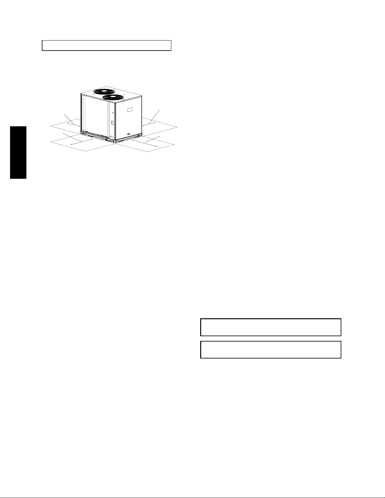
575J*08G/H
UNIT
575J*08G/H
Standard
Weight
Corner
A
Corner
B
Corner
C
Corner
D
Center of Gravity
Unit Height
lbs. kg. lbs. kg. lbs. kg. lbs. kg. lbs. kg. X Y Z H
470 213 156 71 106 48 86 39 120 54
21
[533]
24
[610]
23
[584]
50-3/8
[1280]
Fig. 2 -- 575J*08G/H Unit Dimensions
C14310
4
Table 1 – Physical Data
575J*08G/H — 60 Hz English
Table 2 – Physical Data
575J*08G/H — 60 Hz SI
NOMINAL CAPACITY (tons) 7.5
OPERATING WEIGHTS (lb)
Round Tube/Plate Fin Coil (Cu/Al) 470
REFRIGERANT TYPE
RTPF Operating Charge, Typical (lb)
RTPF Shipping Charge (lb) 9.0
Metering Device Acutrol
COMPRESSOR
Qty...Type 1...Digital Scroll
Oil Charge (oz) 60
CONDENSER FANS
Qty...Rpm 2...1100
Motor Hp
Diameter 22
Nominal Airflow (Cfm Total) 6000
Watts (Total) 610
RTPF CONDENSER COIL
Material (Tube/Fin) Cu / Al
Coil Type RTPF
Rows/Fins per inch (FPI) 2/17
Face Area (sq ft total) 23.0
CONTROLS
Pressurestat Settings (psig)
High Cutout 630 10
Cut-in 505 20
Low Cutout 27 3
Cut-in 44 5
PIPING CONNECTIONS (in. ODS)
Qty...Suction 1...11/
Qty...Liquid 1...1/
LEGEND
RTPF — Round Tube/Plate Fin
ODS — Outside Diameter Sweat (socket)
‡
Unit is factory-supplied with par tial charge only.
†
Typical operating charge with 25 ft of interconnecting piping.
‡
†
R-410A
24.0
1
/
4
NOMINAL CAPACITY (kW) 26.4
OPERATING WEIGHTS (lb)
Round Tube/Plate Fin Coil (Cu/Al) 213
REFRIGERANT TYPE
RTPF Operating Charge, Typical (kg)
RTPF Shipping Charge (kg) 4.1
Metering Device Acutrol
COMPRESSOR
Qty...Type 1...Digital Scroll
Oil Charge (liters) 1.8
CONDENSER FANS
Qty...r/s 2...18
Motor Hp NEMA
Diameter (mm) 560
Nominal Airflow (L/s) 2832
Watts (Total) 610
RTPF CONDENSER COIL
Material (Tube/Fin) Cu / Al
Coil Type RTPF
Rows/Fins per Meter (Fins/m) 2 / 670
Face Area (sq m total) 2.1
CONTROLS
Pressurestat Settings (kPa)
High Cutout 4347 70
Cut-in 3482 138
Low Cutout 186 21
Cut-in 303 35
PIPING CONNECTIONS (in. ODS)
8
2
Qty...Suction 1...11/
Qty...Liquid 1...1/
LEGEND
RTPF — Round Tube/Plate Fin
NEMA — National Electrical Manufacturers Association
ODS — Outside Diameter Sweat (socket)
‡
Unit is factory-supplied with par tial charge only.
†
Typical operating charge with 25 ft of interconnecting piping.
‡
†
R-410A
10.9
1
/
4
575J*08G/H
8
2
.INSTALLATION
Jobsite Survey
Complete the following checks before installation.
1. Consult local building codes and the NEC (National
Electrical Code) ANSI/NFPA 70 for special installation requirements.
2. Determine unit location (from project plans) or select
unit location.
3. Check for possible overhead obstructions which may
interfere with unit lifting or rigging.
Step 1 — Plan for Unit Location
Select a location for the unit and its support system (pad,
rails or other) that provides for the minimum clearances
required for safety. This includes the clearance to
combustible surfaces, unit performance and service access
below, around and above unit as specified in unit
drawings. See Fig. 3.
Select a unit mounting system that provides adequate
height to allow for removal and disposal of frost and ice
that will form during the heating-defrost mode.
NOTE: Consider also the effect of adjacent units on
airflow performance and control box safety clearance.
Do not install the outdoor unit in an area where fresh air
supply to the outdoor coil may be restricted or when
recirculation from the condenser fan discharge is possible.
Do not locate the unit in a well or next to high walls.
Evaluate the path and required line length for
interconnecting refrigeration piping, including vapor riser
requirements and liquid line lift; a heat pump system will
5
have one of each type in opposite modes. Relocate
sections to minimize the length of interconnecting tubing.
Step 3 — Prepare Unit Mounting Support
Slab Mount —
DO NOT BURY REFRIGERATION LINES.
Although unit is weatherproof, avoid locations that permit
water from higher level runoff and overhangs to fall onto
the unit.
RIGHT:
REAR:
Min 18” (457 mm)
requried for service
LEFT:
Min 18” (457 mm)
requried for service
Note: Observe requirements for 39” (914 mm) operating clearance
on either Left or Rear coil opening.
Min 18” (457 mm)
requried for service
575J*08G/H
Fig. 3 -- Service Clearance Dimensional Drawing
Step 2 — Complete Pre-Installation Checks
Check Unit Electric Characteristic —
Confirm before installation of unit that voltage, amperage
and circuit protection requirements listed on unit data
plate agree with power supply provided.
Un--crate Unit —
Remove unit packaging except for the top skid assembly,
which should be left in place until after the unit is rigged
into its final location.
Inspect Shipment —
File a claim with shipping company if the shipment is
damaged or incomplete.
Consider System Requirements —
FRONT:
42” (1067 mm)
C11035
Provide a level concrete slab that extends a minimum of 6
in. (150 mm) beyond unit cabinet. Install a gravel apron in
front of condenser coil air inlet to prevent grass and
foliage from obstructing airflow.
Step 4 — Rig and Mount the Unit
Rigging —
These units are designed for overhead rigging. Refer to
the rigging label for preferred rigging method. Spreader
bars are required. Use the wooden top skid, when rigging,
to prevent rigging straps from damaging the unit. All
panels must be in place when rigging. As further
protection for coil faces, plywood sheets may be placed
against the sides of the unit, behind cables. Run cables to
a central suspension point so that the angle from the
horizontal is not less than 45 degrees. Raise and set the
unit down carefully.
If it is necessary to roll the unit into position, mount the
unit on longitudinal rails, using a minimum of 3 rollers.
Apply force to the rails, not the unit. If the unit is to be
skidded into position, place it on a large pad and drag it
by the pad. Do not apply any force to the unit.
Raise from above to lift the unit from the rails or pad
when unit is in its final position.
After the unit is in position, remove all shipping materials
and top crating.
Step 5 — Complete Refrigerant Piping
Connections
Refrigerant lines must be carefully designed and
constructed to ensure equipment reliability and efficiency.
Line length, pressure drop, compressor oil return, and
vertical separation are several of the design criteria that
must be evaluated. See Table 3.
S Consult local building codes and National Electrical
Code (NEC, U.S.A.) for special installation
requirements.
S Allow sufficient space for airflow clearance, wiring,
refrigerant piping, and servicing unit. See Fig. 2 for unit
dimensions and weight distribution data.
S Locate the unit so that the outdoor coil (condenser)
airflow is unrestricted on all sides and above.
S The unit may be mounted on a level pad directly on the
base channels or mounted on raised pads at support
points. See Tables 1 and 2 for unit operating weights.
See Fig. 2 for weight distribution based on
recommended support points.
NOTE: If vibration isolators are required for a particular
installation, use the data in Fig. 2 to make the proper
selection.
IMPORTANT: Do not bury refrigerant piping
underground.
IMPORTANT: A refrigerant receiver is not
provided with the unit. Do not install a receiver.
Check Vertical Separation —
If there is any vertical separation between the indoor and
outdoor units, check to ensure that the separation is within
allowable limits. Relocate equipment if necessary.
Provide Safety Relief —
If local codes dictate an additional safety relief device,
purchase locally and install locally. Installation will
require the recovery of the factory shipping charge before
the factory tubing can be cut and the supplemental relief
device is installed.
6
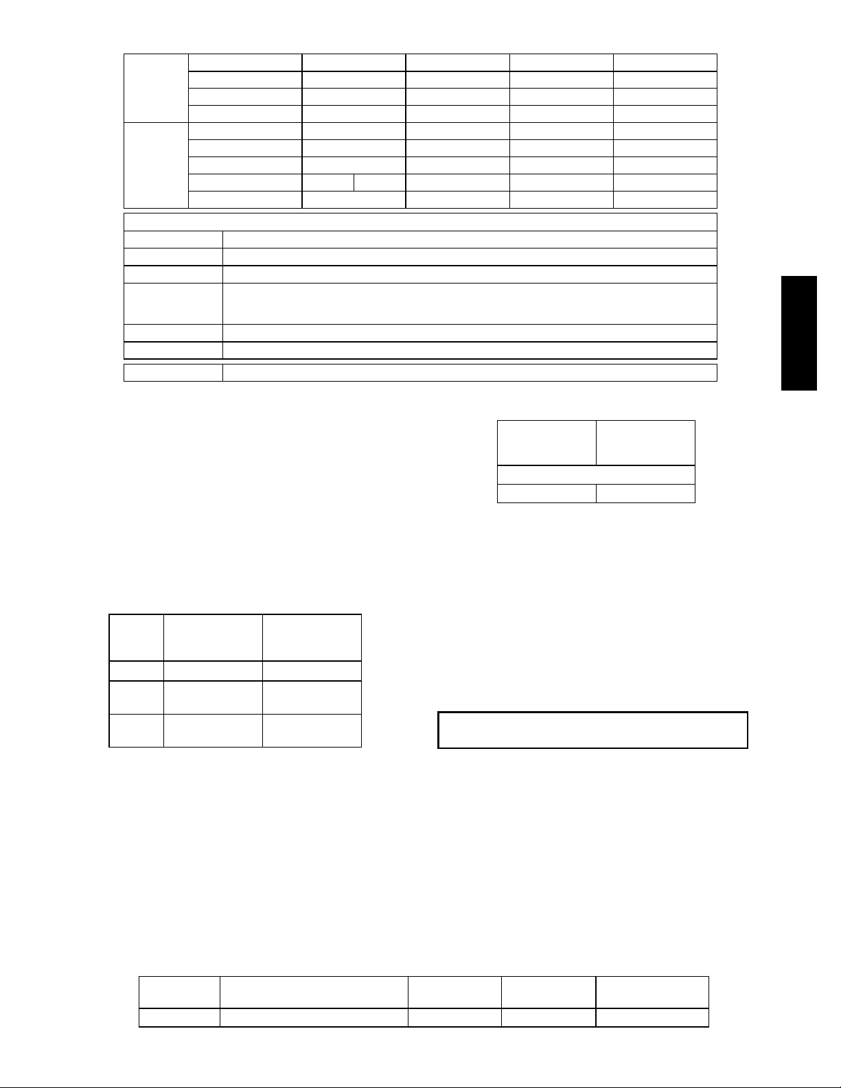
Table 3 – 575J*08G/H Piping Recommendations
Model &
Nominal
capacity
Legend:
Linear Line Linear tubing length, feet
Equivalent Line Equivalent tubing length, including effects of refrigeration specialties devices
Liquid Line size Tubing size, inches OD.
Max Lift
Vapor Line size Tube size, inches OD
Charge Charge Quantity, lbs.
NOTE: For applications with linear length greater than 100 ft (30.5 m), contact your local Bryant representative.
Linear Line (ft) 0 --- 2 5 25 --- 50 50--- 75 75--- 100
Linear Line (m) 0 --- 8 8 --- 1 5 8 --- 15 15 --- 23
Equiv. Line (ft) 0 --- 3 8 38 --- 75 75 --- 113 113--- 150
Equiv. Line (m) 0 --- 12 12 --- 23 12 --- 23 23 --- 34
Liquid Line size
Max Lift Cool 25 50 75 100
Max Lift Heat 25 50 50 60
Vapor Line size
575J*08G/H
Charge (lbs) 23.9 26.0 27.9 29.8
Cool
Heat
Maximum liquid lift at maximum permitted pressure drop
S Indoor unit ABOVE outdoor unit
S Indoor unit BELOW outdoor unit
1
/2”
7
/8” 11/8” 11/8” 11/8” 11/8”
1
/2”
1
/2”
1
/2”
575J*08G/H
Refrigerant Line Sizing —
Consider the length of the piping required between the
outdoor and indoor units. The maximum allowable line
length is 100 ft (30.5 m). See Table 3. Refrigerant vapor
piping should be insulated.
Risers in Heat Pump Piping Systems —
Elevation differences between the outdoor unit and the
indoor unit in heat pump systems will create two riser line
conditions – one in the liquid line in one mode and one in
the vapor line in the opposite mode. See the following
table to identify which lines are risers in this installation.
575J Unit
Mode
Cooling Liquid
Heating
BELOW
ID Unit
Riser in Riser in
Vapor
(Discharge Gas)
575J Unit
ABOVE
ID Unit
Vapor
(Suction Gas)
Liquid
Liquid Line Riser: Refer to Pipe Sizing Table, Table 3;
observe Max Lift limits for liquid line according to unit
mode, equivalent line length and pipe size.
VaporLineRiser:Refer to Table 4 for maximum pipe
size in single pipe vapor risers. All pipe size
recommendations in Pipe Sizing Table, Table 3, satisfy
these maximum vapor line sizes. If this installation is
re--using existing piping, check the vapor line sizes
against these maximum values; replace riser sections with
these pipe sizes if necessary.
Table 4 – Maximum Vapor Line Sizes
575J Unit
BELOW
ID Unit
Max Diameter, Single Pipe (in.)
1-3/
8
575J Unit
ABOVE
ID Unit
1-5/
8
Install Filter Drier and Moisture Indicator —
Every unit MUST have a bi-directional filter drier in the
liquid line. Locate the filter drier(s) at the indoor unit, close
to the indoor coil’s thermal expansion valve (TXV) inlets.
575J units include one Puron-duty filter drier, shipped in
cartons attached to the unit basepan. Remove the filter
drier and prepare to install in the liquid line at the indoor
coil. Do not remove connection fitting plugs until ready to
connect and braze the filter drier into the liquid line
position. See Table 5.
IMPORTANT: A refrigerant receiver is not
provided with the unit. Do not install a receiver.
Installation of liquid line moisture indicating sightglass is
recommended. Locate the sightglass(es) between the
outlet of the filter drier and the TXV inlet.
Refer to Table 5 for recommendations on refrigeration
specialties.
Select the filter drier for maximum unit capacity and
minimum pressure drop. Complete the refrigerant piping
from the indoor unit to the outdoor unit before opening
the liquid and vapor service valves at the outdoor unit.
LIQUID LINE
SIZE (in.)
1
/
2
Table 5 – Refrigerant Specialties Part Numbers
LIQUID LINE
SOLENOID VALVE (LLSV)
EF680035 plus EF680039 biflow kit EF680037 KM680004 KH43LG089
SOLENOID
COIL
7
SIGHT
GLASS
FILTER
DRIER

Install Liquid Line Solenoid Valves —
A
It is recommended that a bi-directional solenoid valve be
placed in the main liquid line (see Fig. 4) between the
outdoor unit and the indoor coil. Locate the solenoid valve
at the end of the liquid line, near the outdoor unit
connections, with flow direction arrow pointed at the
outdoor unit. Refer to Table 5. (A liquid line solenoid
valve is required when the liquid line length exceeds 75 ft
[23 m].) This valve prevents refrigerant migration (which
causes oil dilution) to the compressor during the off cycle,
at low outdoor ambient temperatures. Wire the solenoid
according to the unit label diagram.
!
CAUTION
1
The stub tube connections include
/4-in SAE service fittings
with Schrader valve cores (see Fig. 5). Before making any
brazed connections to the unit service valves, remove both
Schrader valve caps and cores and save for re-installation.
Connect a source for nitrogen to one of these service fittings
during tube brazing to prevent the formation of copper
oxides inside the tubes at brazed joints.
Field Service
Factory
High-Flow
ccess Port
Access Port
(Schrader core)
UNIT DAMAGE HAZARD
Failure to follow this caution may result in equipment
damage.
Failure to use a solenoid valve relay (SVR) PNO
HN61PC005 may cause overload of Comfort Alert
575J*08G/H
Diagnostic Module (CADM) and compressor alarm
lock out.
CAPACITY CONTROL LIQUID LINE SOLENOID
VALVE -- 575J units are single--stage only designs. DO
NOT USE a capacity control liquid line solenoid valve on
the indoor coil.
8 DIAMS
MIN
EQUALIZER LINE
SIGHT GLASS
A LOCATION
TXV
INDOOR
COIL CKT
AIRFLOW
TXV
SENSING
BULB
15 DIAMS
MIN
10
DIAMS
FILTER DRIER
A LOCATION
Fig. 5 -- Typical Piping Connection Assembly
When connecting the field tubing to the 575J service
valves, wrap the valves in wet rags to prevent overheating
Pressure-test all joints from outdoor unit connections over
to the indoor coil, using nitrogen as pressure and with
soap-and-bubbles.
When pressure-testing is completed, remove the nitrogen
source at the outdoor unit service valves and re-install the
two Schrader valve cores. Torque the cores to 2-3 in-lbs
(23-34 N-cm).
Where vapor line is exposed to outdoor air, line must be
insulated. See Table 7 for insulation requirements.
Table 7 – Insulation for Vapor Line Exposed
Service Valve
with Stem Cap
Sweat
Connection
C10203
to Outdoor Conditions
LEGEND
TXV — Thermostatic Expansion Valve
C11036
Fig. 4 -- Location of Sight Glass and Filter Drier
Table 6 – Minimum Outdoor Air Operating Temperature
UNIT
575J*08G/H 100 35 (1.7) –20 (–28.9)
* Applies to Cooling mode of operation only.
† Wind baffles (f ield-su pplied and field-installed) are recommended for all
units with low ambient head pressure control. Refer to Low Ambient
Control Installation Instructions (shipped with accessory) for details.
%
COMPRESSOR
CAPACITY
MINIMUM OUTDOOR
TEMP — F (C)*
Standard Unit
Head Pressure
Control
†
Make Piping Connections —
Piping connections at the 575J unit are ball valves with
stub tube extensions. Do not open the unit service valves
LENGTH OF EXPOSED
VAPOR LINE*
ft m in. mm
10 3
25 8
35 11
50 15
* Recommended vapor line insulation for piping exposed to outdoor
conditions to prevent loss of heating during heating cycle. When vapor
line goes through interior spaces, insulation should be selected to prevent condensation on cooling cycle. Heating capacity should be reduced 1000 Btuh (295 W) if over 35 ft (11 m) of vapor line with
mm) insu lation is exposed to outdoor con ditions.
† Closed cell foam insulation with a thermal conductivity of: 0.28 Btu S
2
in./ft
S h S F (0.04 W/m S C).
INSULATION THICKNESS
3
/
8
1
/
2
3
/
4
3
/
4
Evacuation/Dehydration —
Evacuate and dehydrate the connected refrigeration
system(s) (excluding the 5757J unit) to 500 microns using
a two-stage vacuum pump attached to the service ports
outside the 575J service valves, following description in
GTAC II, Module 4, System Dehydration.
10
13
19
19
†
3
/4in. (19
until all interconnecting tube brazing as been completed.
8
!
WARNING
UNIT OPERATION AND SAFETY HAZARD
Failure to follow this warning could cause personal
injury, death and/or equipment damage.
R
Puron
higher pressures than standard R--22 systems. Do not
use R--22 service equipment or components on Puron
refrigerant equipment.
IMPORTANT: Charge in Cooling mode only!
Preliminary Charge —
Before starting the unit, charge R-410A liquid refrigerant
into the high side of the 575J circuit through the liquid
service valve. The amount of refrigerant added must be at
least 80% of the operating charge listed in Table 3 for
LINEAR line length LESS the factory charge quantity (if
factory shipping charge has not been removed). See the
following example.
Allow high and low side pressures to equalize. If pressures
do not equalize readily, charge R-410A vapor (using
special service manifold with expansion device) into the
vapor line service port for the low side of system to assure
charge in the evaporator. Refer to GTAC II, Module 5,
Charging, Recover, Recycling, and Reclamation for liquid
charging procedures.
Example:
575J*08G/H
60-ft (18.3 m) linear line length
Equivalent line length 90-ft (27.4 m)
Liquid Lift: 20-ft (6.1 m)
Select line sizes from Table 3:
Liquid
Vapor 1-
Charge 27.9 lbs (at 75-ft linear length)
80% of Operating Charge:
0.80 x 27.9 = 22.3 lbs
Factory Shipping Charge: 9 lbs
Field-charge quantity: 22.3 lbs – 9.0 lbs = 13.3 lbs
For linear line lengths longer than 100 ft (30.5 m), contact
your local Bryant representative for system charge value.
(R--410A) refrigerant systems operate at
1
/2in
1
/8in.
Step 6 — Install Accessories
Accessories requiring modifications to unit wiring should
be completed now. These accessories may include Winter
Start controls, Low Ambient controls, phase monitor,
Compressor LOCout. Refer to the instructions shipped
with the accessory.
Step 7 — Complete Electrical Connections
!
WARNING
ELECTRICAL SHOCK HAZARD
Failure to follow this warning could result in personal
injury or death.
Do not use gas piping as an electrical ground. Unit
cabinet must have an uninterrupted, unbroken electrical
ground to minimize the possibility of personal injury if
an electrical fault should occur. This ground may consist
of electrical wire connected to unit ground lug in control
compartment, or conduit approved for electrical ground
when installed in accordance with NEC (National
Electrical Code); ANSI/NFPA 70, latest edition (in
Canada, Canadian Electrical Code CSA [Canadian
Standards Association] C22.1), and local electrical
codes.
NOTE: Field-supplied wiring shall conform with the
limitations of minimum 63F(33C) rise.
Field Power Supply —
If equipped with optional Powered Convenience Outlet:
The power source leads to the convenience outlet’s
transformer primary are not factory connected. Installer
must connect these leads according to required operation
of the convenience outlet. If an always-energized
convenience outlet operation is desired, connect the
source leads to the line side of the unit-mounted
disconnect. (Check with local codes to ensure this method
is acceptable in your area.) If a de-energize via unit
disconnect switch operation of the convenience outlet is
desired, connect the source leads to the load side of the
unit disconnect. On a unit without a unit-mounted
disconnect, connect the source leads to compressor
contactor C and indoor fan contactor IFC pressure lugs
with unit field power leads.
Refer to Fig. 11 for power transformer connections and the
discussion on connecting the convenience outlet on page 11.
Field power wires are connected to the unit at line-side
pressure lugs on compressor contactor C and TB1 (see
wiring diagram label for control box component
arrangement) or at factory-installed option non-fused
disconnect switch. Max wire size is #4 AWG (copper only).
NOTE: TEST LEADS - Unit may be equipped with short
leads (pigtails) on the field line connection points on
contactor C or optional disconnect switch. These leads are
for factory run-test purposes only; remove and discard
before connecting field power wires to unit connection
points. Make field power connections directly to line
connection pressure lugs only.
575J*08G/H
9

!
WARNING
FIRE HAZARD
Failure to follow this warning could result in
intermittent operation or performance satisfaction.
Do not connect aluminum wire between disconnect
switch and condensing unit. Use only copper wire.
(See Fig. 6.)
ELECTRIC
DISCONNECT
SWITCH
COPPER
WIRE ONLY
ALUMINUM
575J*08G/H
WIRE
Fig. 6 -- Disconnect Switch and Unit
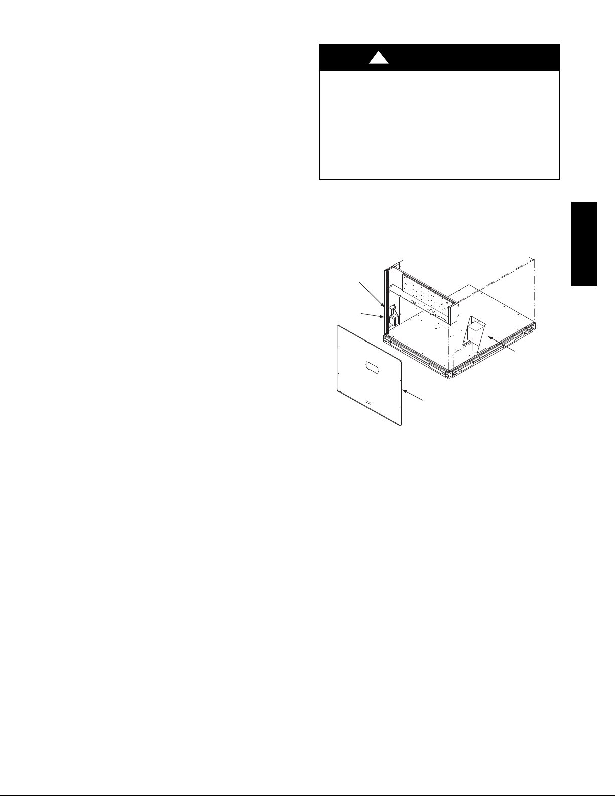
Units with Factory-Installed Non--Fused Disconnect —
The factory-installed option non--fused disconnect (NFD)
switch is located in a weatherproof enclosure located
under the main control box.The manual switch handle and
shaft are shipped in the disconnect enclosure. Assemble the
shaft and handle to the switch at this point. Discard the
factory test leads (see Fig. 7).
Units Without Disconnect Option
CTB1
11 1 3
Disconnect
per
NEC
L1
L2 L3
208/230-3-60
460-3-60
575-3-60
A93033
C12284
Fig. 8 -- Location of Non--Fused Disconnect Enclosure
To field install the NFD shaft and handle:
1. Remove the unit front pane (see Fig. 2).
2. Remove (3) hex screws on the NFD enclosure -- (2) on
the face of the cover and (1) on the left side cover.
3. Remove the front cover of the NFD enclosure.
4. Make sure the NFD shipped from the factory is at
OFF position (the arrow on the black handle knob is
at OFF).
5. Insert the shaft with the cross pin on the top of the shaft
in the horizontal position.
6. Measure from the tip of the shaft to the top surface of
the black pointer; the measurement should be 3.75 --
3.88 in. (95 -- 99 mm).
7. Tighten the locking screw to secure the shaft to the
NFD.
8. Turn the handle to the OFF position with red arrow
pointing at OFF.
9. Install the handle on to the painted cover horizontally
with the red arrow pointing to the left.
10. Secure the handle to the painted cover with (2) screws
and lock washers supplied.
11. Engaging the shaft into the handle socket, re--install
(3) hex screws on the NFD enclosure.
12. Re--install the unit front panel.
Units With Disconnect Option
L1
L2
L3
2
4
6
Optional
Disconnect
Switch
1
3
5
Factory
Wiring
Disconnect factory test leads; discard.
C10204
Fig. 7 -- Power Wiring Connections
Connect field power supply conductors to LINE side
terminals when the switch enclosure cover is removed to
attach the handle.
C12279
Fig. 9 -- Handle and Shaft Assembly for NFD
10
UnitsWithout Factory-Installed
Non--Fused Disconnect —
Convenience Outlets
When installing units, provide a disconnect switch per
NEC (National Electrical Code) of adequate size.
Disconnect sizing data is provided on the unit informative
plate. Locate on unit cabinet or within sight of the unit per
national or local codes. Do not cover unit informative
plate if mounting the disconnect on the unit cabinet.
All Units -
All field wiring must comply with NEC and all local
codes. Size wire based on MCA (Minimum Circuit Amps)
on the unit informative plate. See Fig. 7 and the unit label
diagram for power wiring connections to the unit power
terminal blocks and equipment ground. Maximum wire
size is #2 ga AWG (copper only) per pole on contactors.
Provide a ground-fault and short-circuit over-current
protection device (fuse or breaker) per NEC Article 440
(or local codes). Refer to unit informative data plate for
MOCP (Maximum Over-current Protection) device size.
All field wiring must comply with the NEC and local
requirements.
All units except 208/230-v units are factory wired for the
voltage shown on the nameplate. If the 208/230-v unit is
to be connected to a 208-v power supply, the control
transformer must be rewired by moving the black wire
with the
connection and moving it to the 208-v
-in. female spade connector from the 230-v
-in. male
terminal on the primary side of the transformer. Refer to
unit label diagram for line-side information. Field power
wires will be connected line--side pressure lugs on the
power terminal block or at factory--installed option
non--fused disconnect.
NOTE: Check all factory and field electrical connections
for tightness.
Affix the crankcase heater warning sticker to the unit
disconnect switch.
Voltage and Current Balance —
Voltage to compressor terminals during operation must be
within voltage range indicated on unit nameplate. See
Table 8. On 3-phase units, voltages between phases must
be balanced within 2% and the current within 10%. Use
the formula shown in the legend for Table 8, Note 4 (see
page 14) to determine the percent of voltage imbalance.
Operation on improper line voltage or excessive phase
imbalance constitutes abuse and may cause damage to
electrical components. Such operation would invalidate
any applicable Bryant warranty.
!
WARNING
ELECTRICAL OPERATION HAZARD
Failure to follow this warning could result in personal
injury or death.
Units with convenience outlet circuits may use
multiple disconnects. Check convenience outlet for
power status before opining unit for service. Locate its
disconnect switch, if appropriate, and open it. Tag--out
this switch, if necessary.
Two types of convenience outlets are offered on 575J
models: Non-powered and unit-powered. Both types provide
a 125-volt GFCI (ground-fault circuit-interrupter) duplex
receptacle rated at 15-A behind a hinged waterproof access
cover, located on the end panel of the unit. See Fig. 10.
Convenience
Outlet
GFCI
Pwd-CO
Fuse
Switch
Pwd-CO
Transformer
Control Box
Access Panel
C11038
Fig. 10 -- Convenience Outlet Location
Non-powered type: This type requires the field
installation of a general-purpose 125-volt 15-A circuit
powered from a source elsewhere in the building. Observe
national and local codes when selecting wire size, fuse or
breaker requirements and disconnect switch size and
location. Route 125-v power supply conductors into the
bottom of the utility box containing the duplex receptacle.
Unit-powered type: A unit-mounted transformer is
factory-installed to stepdown the main power supply
voltage to the unit to 115-v at the duplex receptacle. This
option also includes a manual switch with fuse, located in
a utility box and mounted on a bracket behind the
convenience outlet; access is through the unit’s control
box access panel. See Fig. 10.
The primary leads to the convenience outlet transformer are
not factory-connected. Selection of primary power source is
a customer-option. If local codes permit, the transformer
primary leads can be connected at the line-side terminals on
the unit-mounted non-fused disconnect or HACR breaker
switch; this will provide service power to the unit when the
unit disconnect switch or HACR switch is open. Other
connection methods will result in the convenience outlet
circuit being de-energized when the unit disconnect or
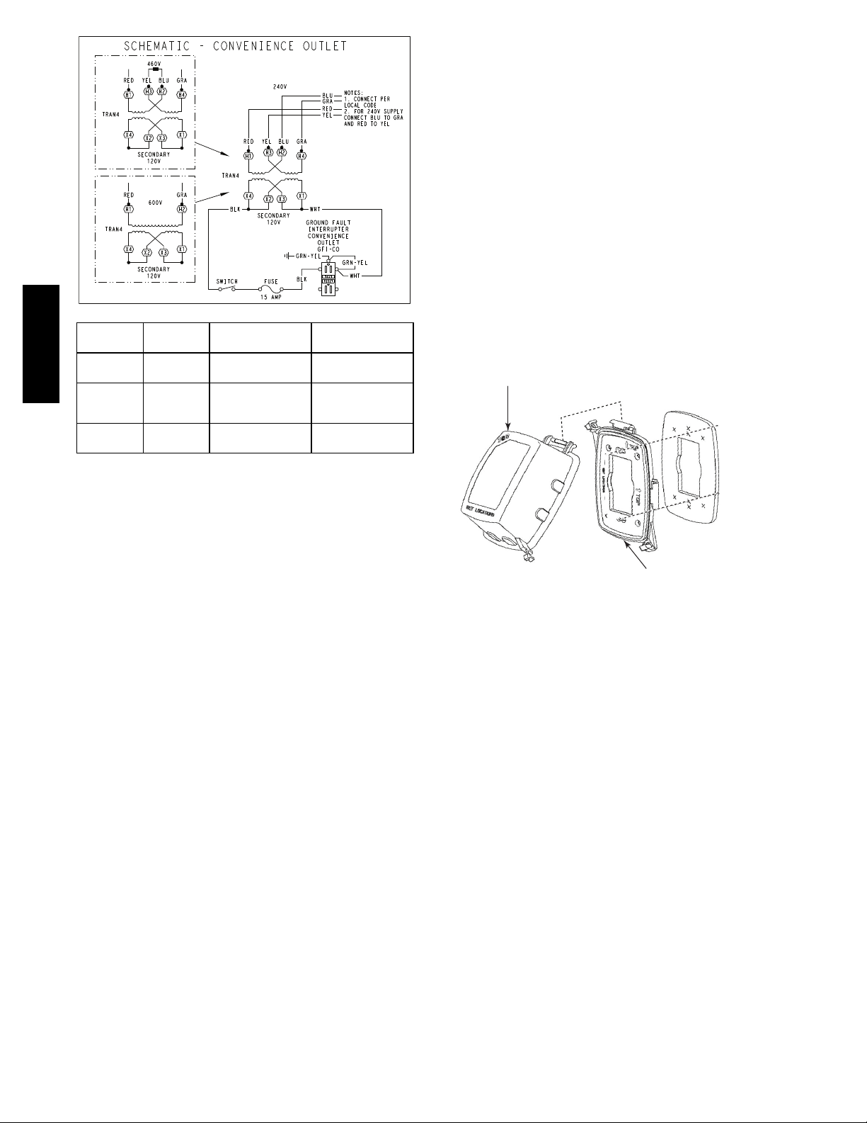
HACR switch is open. See Fig. 11.
11
575J*08G/H
The weatherproof cover kit is shipped in the unit’s control
box. The kit includes the hinged cover, a backing plate
and gasket.
DISCONNECT ALL POWER TO UNIT AND
CONVENIENCE OUTLET.
Remove the blank cover plate at the convenience outlet;
discard the blank cover.
UNIT
VOLTAGE
208,
575J*08G/H
230
460 480
575 600
CONNECT
AS
240
PRIMARY
CONNECTIONS
L1: RED + YEL
L2: BLU + GRA
L1: RED
Splice BLU + YEL
L2: GRA
L1: RED
L2: GRA
TRANSFORMER
TERMINALS
H2 + H3
Fig. 11 -- Powered Convenience Outlet Wiring
Duty Cycle: The unit-powered convenience outlet has a
duty cycle limitation. The transformer is intended to
provide power on an intermittent basis for service tools,
lamps, etc; it is not intended to provide 15-amps loading
for continuous duty loads (such as electric heaters for
overnight use). Observe a 50% limit on circuit loading
above 8-amps (i.e., limit loads exceeding 8-amps to 30
minutes of operation every hour).
H1 + H3
H2 + H4
H1
H4
H1
H2
C10206
Loosen the two screws at the GFCI duplex outlet, until
1
approximately
/2in (13 mm) under screw heads are
exposed. Press the gasket over the screw heads. Slip the
backing plate over the screw heads at the keyhole slots
and align with the gasket; tighten the two screws until
snug (do not overtighten).
Mount the weatherproof cover to the backing plate as
shown in Fig. 12. Remove two slot fillers in the bottom of
the cover to permit service tool cords to exit the cover.
Check for full closing and latching.
COVER – WHILE-IN-USE
WEATHERPROOF
RECEPTACLE
NOT INCLUDED
BASE PLATE FOR
GFCI RECEPTACLE
C09022
Fig. 12 -- Weatherproof Cover Installation
Test the GFCI receptacle by pressing the TEST button on
the face of the receptacle to trip and open the receptacle.
Check for proper grounding wires and power line phasing
if the GFCI receptacle does not trip as required. Press the
RESET button to clear the tripped condition.
Fuse on power type: The factory fuse is a Bussman
“Fusetron” T-15, non-renewable screw-in (Edison base)
type plug fuse.
Using unit-mounted convenience outlets: Units with
unit-mounded convenience outlet circuits will often
require that two disconnects be opened to de-energize all
power to the unit. Treat all units as electrically energized
until the convenience outlet power is also checked and
de-energization is confirmed. Observe National Electrical
Code Article 210, Branch Circuits, for use of convenience
outlets.
Installing Weatherproof Cover
A weatherproof while--in--use cover for the factory
installed convenience outlets is now required by UL
standards. This cover cannot be factory mounted due its
depth; it must be installed at unit installation. For
shipment, the convenience outlet is covered with a blank
cover plate.
NOTE: Check all factory and field electrical connections
for tightness.
Field Control Wiring —
575J unit control voltage is 24 v. See Fig. 17 for typical field
control connections and the unit’s label diagram for
field-supplied wiring details. Route control wires to the 575J
unit through the opening in unit’s end panel to the
connections terminal board in the unit’s control box.
Remainder of the system controls connection will vary
according to the specific construction details of the indoor
section. Fig. 13 depicts typical connections to a Bryant
524J fan coil unit. Plan for field connections carefully and
install control wiring correctly per the project plan.
Additional components and supplemental transformer
accessory may be required.
The 575J unit requires an external temperature control
device. This device can be a thermostat (field-supplied)
or a thermostat emulation device provided as part of a
third--party Building Management System).
12
 Loading...