

Bryant 574DNWA24060NA, 574DNWA24040AA, 574DNWA30040AA, 574DNWA30040NA, 574DPWA30040AA Installation Instructions Manual
...
574D----A
LEGACYt 13 SEER SINGLE--PACKAGED AIR CONDITIONER AND
GAS FURNACE SYSTEM WITH PURONR (R--410A) REFRIGERANT
SINGLE AND THREE PHASE
2--5 NOMINAL TONS (SIZES 24--60)
Installation Instructions
NOTE: Read the entire instruction manual before starting the
installation.
NOTE: Installer: Make sure the Owner’s Manual and Service
Instructions are left with the unit after installation.
TABLE OF CONTENTS
PAGE
SAFETY CONSIDERATIONS 1.........................
INTRODUCTION 2...................................
RECEIVING AND INSTALLATION 2--12.................
Check Equipment 2..................................
Identify Unit 2....................................
Inspect Shipment 2.................................
Provide Unit Support 2...............................
Roof Curb 2......................................
Slab Mount 6.....................................
Field Fabricate Ductwork 6............................
Provide Clearances 6.................................
Rig and Place Unit 6.................................
Inspection 6......................................
Rigging/Lifting 6..................................
Connect Condensate Drain 9...........................
Install Flue Hood 9...................................
Install Gas Piping 9..................................
Install Duct Connections 10............................
Configuring Units for Downflow (Vertical)
Discharge 10.....................................
Install Electrical Connections 11........................
High--Voltage Connections 11........................
Special Procedures for 208--V Operation 12..............
Control Voltage Connections 12.......................
Standard Connection 12.............................
Heat Anticipator Setting 12..........................
Transformer Protection 12...........................
PRE-- START--UP 13...................................
START--UP 13--21.....................................
Check for Refrigerant Leaks 13.........................
Start--Up Heating & Make Adjustments 13................
Check Heating Control 14...........................
Check Gas Input 14................................
Adjust Gas Input 14................................
Check Burner Flame 15.............................
Normal Operation 22...............................
Airflow and Temperature Rise 22......................
Heating Sequence of Operation 22.....................
Limit Switches 22.................................
Rollout Switch 22.................................
Start--Up Cooling & Make Adjustments 22................
Checking Cooling Control Operation 22................
Checking & Adjusting Refrigerant Charge 22............
Indoor Airflow and Airflow Adjustments 23.............
Continuous Fan Operation 23........................
Cooling Sequence of Operation 24.....................
MAINTENANCE 31--34................................
Air Filter 31......................................
Indoor Blower and Motor 31.........................
Induced Draft (Combustion Air) Blower 32..............
Flue Gas Passageways 32............................
Limit Switch 32...................................
Burner Ignition 32.................................
Main Burners 32...................................
Removal of Gas Train 32............................
Outdoor Coil, Indoor Coil, & Condensate Drain Pan 32....
Outdoor Fan 33...................................
Electrical Controls and Wiring 34.....................
Refrigerant Circuit 34...............................
Gas Input 34......................................
Evaporator Airflow 34..............................
Puron Items 34....................................
TROUBLESHOOTING 35..............................
START--UP CHECKLIST 35............................
VERTICAL ECONOMIZER 40--57.......................
General 40.........................................
Accessories 40......................................
Installation 40......................................
Small Chassis 40--41...............................
Large Chassis 44--46...............................
CONFIGURATION 47--55..............................
OPERATION 56......................................
TROUBLESHOOTING 57..............................
Improper installation, adjustment, alteration, service maintenance,
or use can cause explosion, fire, electrical shock, or other
conditions which may cause death, personal injury, or property
damage. Consult a qualified installer, service agency, or your
distributor or branch for information or assistance. The qualified
installer or agency must use factory-- authorized kits or accessories
when modifying this product. Refer to the individual instructions
packaged with the kits or accessories when installing.
Follow all safety codes. Wear safety glasses, protective clothing,
and work gloves. Have a fire extinguisher available. Read these
instructions thoroughly and follow all warnings or cautions
included in literature and attached to the unit. Consult local
building codes, the current editions of the National Fuel Gas Code
(Low NOx Model Available)
SAFETY CONSIDERATIONS
A09034
Fig. 1 -- Unit 574D-- -- A
1

(NFGC) NFPA 54/ANSI Z223.1, and the National Electrical Code
(NEC) NFPA 70.
In Canada refer to the current editions of the National Standards of
Canada CAN/CSA--B149.1 and .2 Natural Gas and Propane
Installation codes, and Canadian Electrical Code CSA C22.1
Recognize safety information. This is the safety--alert symbol
When you see this symbol on the unit and in instructions or manuals, be alert to the potential for personal injury. Understand these
signal words: DANGER, WARNING, and CAUTION. These
words are used with the safety--alert symbol. DANGER identifies
the most serious hazards which will result in severe personal injury
or death. WARNING signifies hazards which could result in personal injury or death. CAUTION is used to identify unsafe practices which may result in minor personal injury or product and property damage. NOTE is used to highlight suggestions which will
result in enhanced installation, reliability, or operation.
!
WARNING
ELECTRICAL SHOCK HAZARD
Failure to follow this warning could result in personal
574D-- --A
injury or death.
Before installing or servicing system, always turn off main
power to system and install lockout tag. There may be
more than one disconnect switch. Turn off accessory heater
power switch if applicable.
!
WARNING
FIRE, EXPLOSION, ELECTRICAL SHOCK AND
CARBON MONOXIDE POISONING HAZARD
Failure to follow this warning could result in personal
injury or unit damage.
A qualified installer or agency must use only
factory--authorized kits or accessories when modifying this
product.
!
CAUTION
CUT HAZARD
Failure to follow this caution may result in personal injury.
When removing access panels (see Fig. 19) or performing
maintenance functions inside your unit, be aware of sharp
sheet metal parts and screws. Although special care is taken
to reduce sharp edges to a minimum, be extremely careful
when handling parts or reaching into the unit.
INTRODUCTION
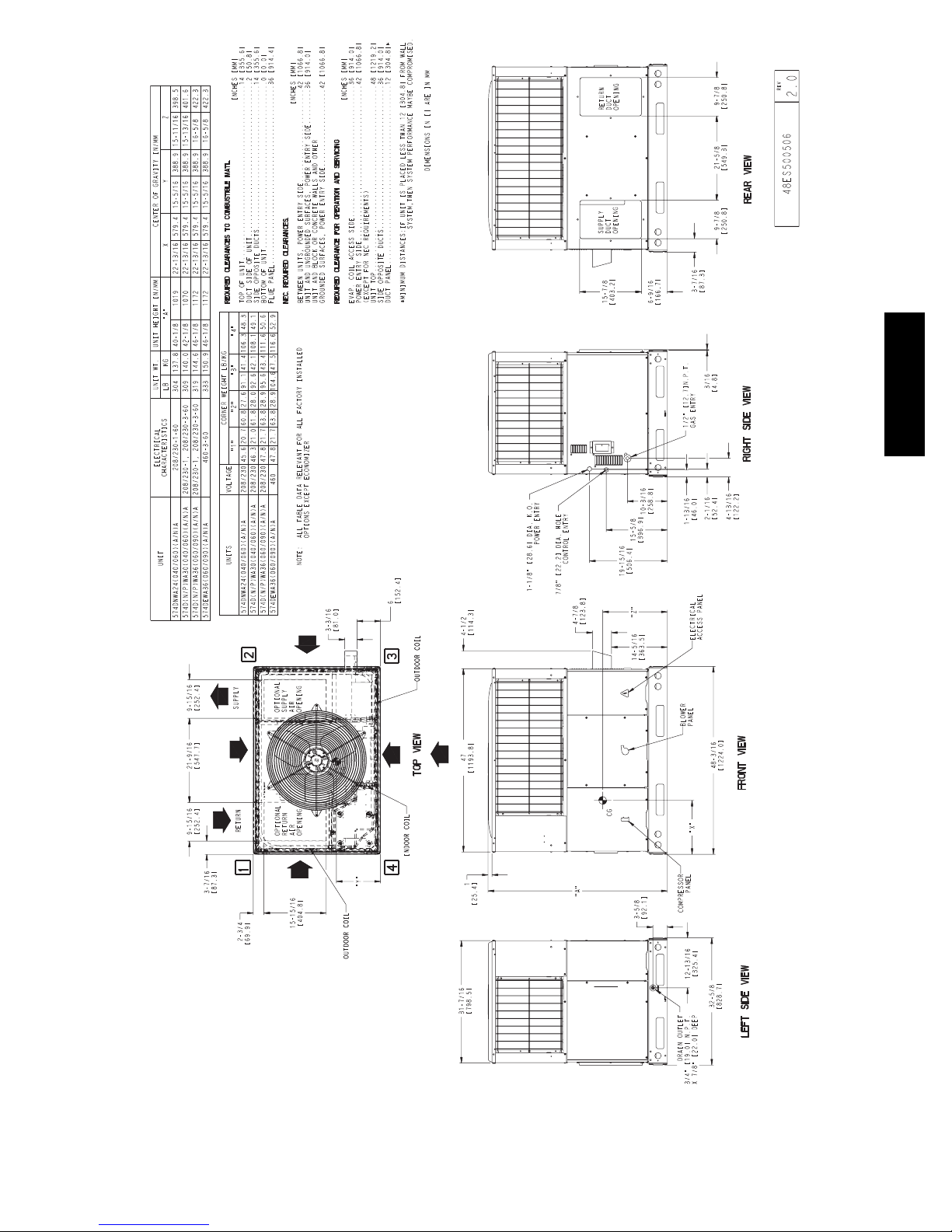
The 574D----A unit (see Fig. 1) is a fully self --contained,
combination Category I gas heating/electric cooling unit designed
for outdoor installation (See Fig. 2 and 3 for unit dimensions). All
unit sizes have return and discharge openings for both horizontal
and downflow configurations, and are factory shipped with all
downflow duct openings covered. Units may be installed either on
a rooftop or on a cement slab. (See Fig. 4 for roof curb
dimensions).
In gas heating mode, this unit is designed for a minimum
continuous return-- air temperature of 55_F(13_C) db and a
maximum continuous return--air temperature of 80_F(27_C) db.
Failure to follow these return--air temperature limits may affect
reliability of heat exchangers, motors, and other components.
Models with an N in the thirteenth position of the model number
are dedicated Low NOx units designed for California installations.
These models meet the California maximum oxides of nitrogen
(NOx) emissions requirements of 40 nanograms/joule or less as
shipped from the factory and must be installed in California Air
Quality Management Districts or any other regions in North
America where a Low NOx rule exists.
NOTE: Low NOx requirements apply only to natural gas
.
installations.
RECEIVING AND INSTALLATION
Step 1 — Check Equipment
Identify Unit
The unit model number and serial number are stamped on the unit
information plate. Check this information against shipping papers.
Inspect Shipment
Inspect for shipping damage before removing packaging materials.
If unit appears to be damaged or is torn loose from its anchorage,
have it examined by transportation inspectors before removal.
Forward claim papers directly to transportation company.
Manufacturer is not responsible for any damage incurred in transit.
Check all items against shipping list. Immediately notify the
nearest equipment distribution office if any item is missing. To
prevent loss or damage, leave all parts in original packages until
installation.
If the unit is to be mounted on a curb in a downflow application,
review Step 9 to determine which method is to be used to remove
the downflow panels before rigging and lifting into place. The
panel removal process may require the unit to be on the ground.
Step 2 — Provide Unit Support
IMPORTANT: The unit must be secured to the curb by installing
screws through the bottom of the curb flange and into the unit base
rails. When installing large base units onto the common curb, the
screws must be installed before allowing the full weight of the unit
to rest on the curb. A minimum of six screws are required for large
base units. Failure to secure unit properly could result in an
unstable unit. See Warning near Rigging/Lifting information and
accessory curb instructions for more details.
For hurricane tie downs, contact distributor for details and PE
(Professional Engineering) Certificate if required.
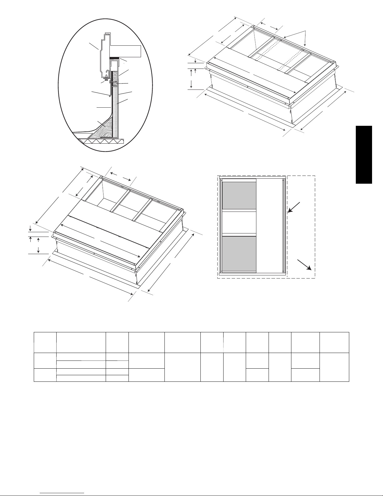
Roof Curb
Install accessory roof curb in accordance with instructions shipped
with curb (See Fig. 4). Install insulation, cant strips, roofing, and
flashing. Ductwork must be attached to curb.
IMPORTANT: The gasketing of the unit to the roof curb is
critical for a water tight seal. Install gasketing material supplied
with the roof curb. Improperly applied gasketing also can result in
air leaks and poor unit performance.
Curb should be level to within 1/4 in. (6 mm). This is necessary
for unit drain to function properly. Refer to accessory roof curb
installation instructions for additional information as required.
Installation on older “G” series roof curbs.
Two accessory kits are available to aid in installing a new “G”
series unit on an old “G” roof curb.
1. Accessory kit number CPADCURB001A00, (small chassis)
and accessory kit number CPADCURB002A00, (large
chassis) includes roof curb adapter and gaskets for the
perimeter seal and duct openings. No additional
modifications to the curb are required when using this kit.
2. An alternative to the adapter curb is to modify the existing
curb by removing the outer horizontal flange and use
accessory kit number CPGSKTKIT001A00 which includes
spacer blocks (for easy alignment to existing curb) and
gaskets for the perimeter seal and duct openings. This kit is
used when existing curb is modified by removing outer
horizontal flange.
2
574D-- --A
A09469
Fig. 2 -- 574D----A24--36 Unit Dimensions
3

574D-- --A
A09470
Fig. 3 -- 574D----A42--60 Unit Dimensions
4
HVAC unit
base rails
Anchor screw
Flashing field
supplied
Roofing material
field supplied
Cant strip
field supplied
HVAC unit
basepan
Sealing
Gasket
Roofcurb
Wood nailer*
Roofcurb*
Insulation
(field supplied)
B
G
C
F
A
H
D
Dashed lines show cross support
location for large basepan units.
E
A09413
*Provided with roofcurb
SMALL/COMMON CURB
A09090
ROOF CURB DETAIL
574D-- --A
B
C
G
SUPPLY
AIR
SMALL
BASE
UNIT
H
A
F
RETURN
E
AIR
LARGE
BASE
UNIT
D
UNIT PLACEMENT ON
LARGE CURB
A09415
COMMON CURB
SMALL OR LARGE BASE UNIT
A09094
UNIT
SIZE
Small
or
Large
Large
* Part Numbers CPRCURB010A00 and CPRCURB011A00 can be used on both small and large basepan u nits. T he cross supports mu st be located based on
whether the unit is a small basepan or a large basepan.
NOTES:
1. Roof curb must be set up for unit being installed.
2. Seal strip must be applied, as required, to unit being installed.
3. Roof curb is made of 16 --gauge steel.
4. Attach ductwork to curb (flanges of duct rest on curb).
5. Insulated panels: 1-- in. (25.4 mm) thick fiberglass 1 lb. density.
CATALOG
NUMBER
CPRFCURB010A00 11 (279)
CPRFCURB011A00 14 (356)
CPRFCURB012A00 11 (279)
CPRFCURB013A00 14 (356)
A
IN.
(mm)
B (small /
common
base)
IN. (mm)*
B (large base)
IN. (mm)*
10 (254)
14 (356) 16 (406)
14 (356)
Fig. 4 -- Roof Curb Dimensions
A09414
C
IN.
(mm)
D
IN.
(mm)
47.8
(1214)
E
IN.
(mm)
32.4
(822)
43.9
(1116)
F
IN.
(mm)
2.7 (69)
G
IN. (mm)HIN. (mm)
30.6 (778)
46.1 (1170)
42.2 (1072)
5
OPTIONAL
RETURN
AIR
OPENING
2˝
(50.8mm)
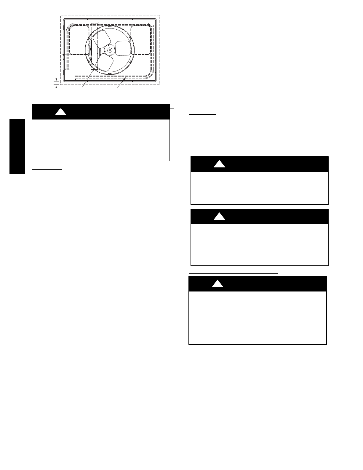
EVAP. COIL COND. COIL
Fig. 5 -- Slab Mounting Details
!
UNIT/STRUCTURAL DAMAGE HAZARD
Failure to follow this caution may result in property damage.
Ensure there is sufficient clearance for saw blade when cutting
the outer horizontal flange of the roof curb so there is no
574D-- --A
damage to the roof or flashing.
CAUTION
OPTIONAL
SUPPLY
AIR
OPENING
Slab Mount
Place the unit on a solid, level concrete pad that is a minimum of 4
in. (102 mm) thick with 2 in. (51 mm) above grade. The slab
should extend approximately 2 in. (51 mm) beyond the casing on
all 4 sides of the unit. (See Fig. 5.) Do not secure the unit to the
slab except when required by local codes.
Step 3 — Field Fabricate Ductwork
Secure all ducts to roof curb and building structure on vertical
discharge units. Do not connect ductwork to unit. For horizontal
applications, unit is provided with flanges on the horizontal
openings. All ductwork should be secured to the flanges. Insulate
and weatherproof all external ductwork, joints, and roof openings
with counter flashing and mastic in accordance with applicable
codes.
Ducts passing through an unconditioned space must be insulated
and covered with a vapor barrier.
If a plenum return is used on a vertical unit, the return should be
ducted through the roof deck to comply with applicable fire codes.
Read unit rating plate for any required clearances around ductwork.
Cabinet return--air static shall not exceed --.25 IN. W.C.
Step 4 — Provide Clearances
The required minimum operating and service clearances are shown
in Fig. 2 and 3. Adequate combustion, ventilation and condenser
air must be provided.
IMPORTANT: Do not restrict outdoor airflow. An air restriction
at either the outdoor--air inlet or the fan discharge may be
detrimental to compressor life.
The condenser fan pulls air through the condenser coil and
discharges it through the top grille. Be sure that the fan discharge
does not recirculate to the condenser coil. Do not locate the unit in
either a corner or under an overhead obstruction. The minimum
clearance under a partial overhang (such as a normal house
overhang) is 48--in. (1219 mm) above the unit top. The maximum
horizontal extension of a partial overhang must not exceed 48--in.
(1219 mm).
Do not place the unit where water, ice, or snow from an overhang
or roof will damage or flood the unit. Do not install the unit on
carpeting or other combustible materials. Slab--mounted units
should be at least 4 in. (102 mm) above the highest expected water
and runoff levels. Do not use unit if it has been under water.
Step 5 — Rig and Place Unit
Rigging and handling of this equipment can be hazardous for
many reasons due to the installation location (roofs, elevated
structures, etc.).
A07926
Only trained, qualified crane operators and ground support staff
should handle and install this equipment.
When working with this equipment, observe precautions in the
literature, on tags, stickers, and labels attached to the equipment,
and any other safety precautions that might apply.
Training for operators of the lifting equipment should include, but
not be limited to, the following:
1. Application of the lifter to the load, and adjustment of the
lifts to adapt to various sizes or kinds of loads.
2. Instruction in any special operation or precaution.
3. Condition of the load as it relates to operation of the lifting
kit, such as balance, temperature, etc.
Follow all applicable safety codes. Wear safety shoes and work
gloves.
Inspection
Prior to initial use, and at monthly intervals, all rigging shackles,
clevis pins, and straps should be visually inspected for any
damage, evidence of wear, structural deformation, or cracks.
Particular attention should be paid to excessive wear at hoist
hooking points and load support areas. Materials showing any kind
of wear in these areas must not be used and should be discarded.
!
WARNING
UNIT FALLING HAZARD
Failure to follow this warning could result in personal
injury or death.
Never stand beneath rigged units or lift over people.
!
WARNING
PROPERTY DAMAGE HAZARD
Failure to follow this warning could result in personal
injury/death or property damage.
When straps are taut, the clevis should be a minimum of 36
in. (914 mm) above the unit top cover.
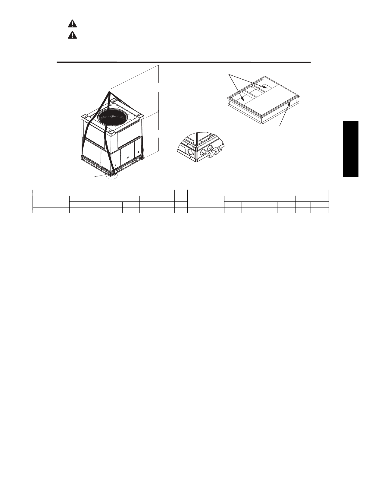
Rigging/Lifting of Unit (See Fig. 6)
!
WARNING
UNIT FALLING HAZARD
Failure to follow this warning could result in personal
injury or death.
Large base units must be secured to common curb before
allowing full weight of unit to rest on curb. Install screws
through curb into unit base rails while rigging crane is still
supporting unit.
Lifting holes are provided in base rails as shown in Fig. 2 and 3.
1. Leave top shipping skid on the unit for use as a spreader bar
to prevent the rigging straps from damaging the unit. If the
skid is not available, use a spreader bar of sufficient length
to protect the unit from damage.
2. Attach shackles, clevis pins, and straps to the base rails of
the unit. Be sure materials are rated to hold the weight of the
unit (See Fig. 6).
3. Attach a clevis of sufficient strength in the middle of the
straps. Adjust the clevis location to ensure unit is lifted level
with the ground.
After the unit is placed on the roof curb or mounting pad, remove
the top skid.
6
CAUTION - NOTICE TO RIGGERS
PRUDENCE - AVIS AUX MANIPULATEUR
PANNEAUX D'ACCES DOIT ÊTRE EN PLACE POUR MANIPULATION.
Use top skid as spreader bar. / Utiliser la palette du haut comme barre de répartition
ACCESS PANELS MUST BE IN PLACE WHEN RIGGING.
DUCTS
MINIMUM HEIGHT: 36" (914.4 mm)
HAUTEUR MINIMUM
SEAL STRIP MUST BE IN
UNIT HEIGHT
HAUTEUR D'UNITÉ
DETAIL A
SEE DETAIL A
VOIR DÉTAIL A
SMALL CABINET LARGE CABINET
Unit *
Rigging Weight 311 141 316 143 326 148 Rigging Weight 420 191 428 194 450 204
* For 460 volt units add 14 lb (6.35 kg) to the rigging weight.
NOTE: See dimensional drawing for corner weights.
24 30 36
lb kg lb kg lb kg lb kg lb kg lb kg
VOIR DÉTAIL A
Unit *
PLACE BEFORE PLACING
UNIT ON ROOF CURB
42 48 60
BANDE SCELLANT DOIT ÊTRE
EN PLACE AVANT DE PLACER
L'UNITÉ SUR LA BASE DE TOIT
50CY502286 2.0
Fig. 6 -- 574D----A Unit Suggested Rigging
574D-- --A
A09051
7
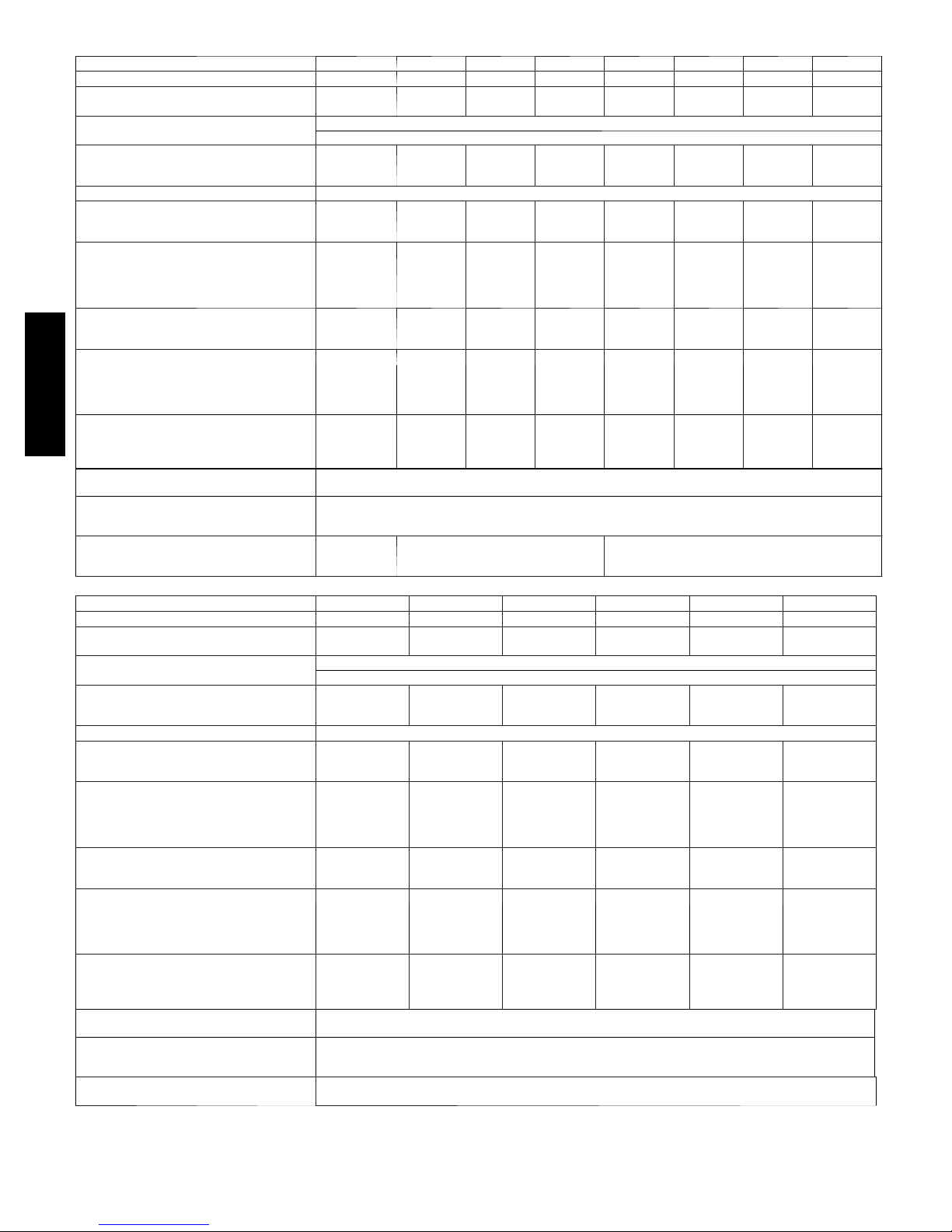
Table 1 – Physical Data -- Unit 574D----A
1600
1600
1600
1750
1750
UNIT SIZE 24040 24060 30040 30060 36060 36090 42060 42090
NOMINAL CAPACITY (ton) 2 2 2 --- 1 / 2 2 --- 1 / 2 3 3 3 --- 1 / 2 3 --- 1 / 2
SHIPPING WEIGHT** lb.
SHIPPING WEIGHT** (kg)
COMPRESSORS
Quantity
REFRIGERANT (R --- 410A)
Quantity lb.
Quantity (kg)
REFRIGERANT METERING DEVICE TXV
OUTDOOR COIL
Rows...Fins/in.
Face Area (sq ft)
OUTDOOR FAN
Nominal CFM
Diameter in.
Diameter (mm)
Motor Hp (Rpm)
INDOOR COIL
Rows...Fins/in.
Face Area (sq ft)
INDOOR BLOWER
Nominal Cooling Airflow (Cfm)
Size in.
Size (mm.)
Motor HP (RPM)
574D-- --A
FURNACE SECTION*
Burner Orifice No. (Qty...Drill Size)
Natural Gas (Factory Installed)
Propane Gas
HIGH-- PRESSURE SWITCH
(psig) Cut --out Reset (Auto)
LOSS--OF--CHARGE / LOW--PRESSURE
SWITCH (Liquid Line) (psig) cut-- out Reset
(auto)
RETURN--- AIR FILTERS†}
Throwaway Size in.
(mm)
311
141
4.8
2.2
1..21
10.2
2800
24
609.6
1/5 (810)
2...17
3.7
800
10x10
254x254
1/2 (1050)
2...44
2...55
20x20x1
508x508x25
311
141
4.8
2.2
1...21
10.2
2800
24
609.6
1/5 (810)
2...17
3.7
800
10x10
254x254
1/2 (1050)
2...38
2...53
316
143
6.2
2.8
1...21
11.9
3000
24
609.6
1/5 (810)
3...17
3.7
1000
10x10
254x254
1/2 (1050)
2...44
2...55
20x24x1
508x610x25
316
143
6.2
2.8
1...21
11.9
3000
24
609.6
1/5 (810)
3...17
3.7
1000
10x10
254x254
1/2 (1050)
2...38
2...53
650 +/-- 15
420 +/-- 25
45 +/-- 10
Scroll
1
20 +/-- 5
326
148
6.4
2.9
1...21
15.4
3200
24
609.6
1/5 (810)
3...17
3.7
1200
11x10
279.4x254
3/4 (1000)
2...38
2...53
326
148
6.4
2.9
1...21
15.4
3200
24
609.6
1/5 (810)
3...17
3.7
1200
11x10
279.4x254
3/4 (1000)
3...38
3...53
610x762x25
24x30x1
420
191
6.1
2.7
1...21
13.6
3600
26
660.4
1/5 (810
3...17
4.7
1400
11x10
279.4x254
3/4 (1075)
2...38
2...53
Table 1—Physical Data Con’t -- Unit 574D-- --A
UNIT SIZE 48090 48115 48130 60090 60115 60130
NOMINAL CAPACITY (ton) 4 4 4 5 5 5
SHIPPING WEIGHT** lb
SHIPPING WEIGHT** kg
COMPRESSORS
Quantity
REFRIGERANT (R --- 410A)
Quantity lb
Quantity (kg.)
REFRIGERANT METERING DEVICE TXV
OUTDOOR COIL
Rows...Fins/in.
Face Area (sq ft)
OUTDOOR FAN
Nominal Cfm
Diameter in.
Diameter (mm)
Motor Hp (Rpm)
INDOOR COIL
Rows...Fins/in.
Face Area (sq ft)
INDOOR BLOWER
Nominal Cooling Airflow (Cfm)
Size in.
Size (mm)
Motor HP (RPM)
FURNACE SECTION*
Burner Orifice No. (Qty...Drill Size)
Natural Gas (Factory Installed)
Propane Gas
HIGH-- PRESSURE SWITCH
(psig) Cut --out Reset (Auto)
LOSS--OF--CHARGE / LOW--PRESSURE
SWITCH (Liquid Line) (psig) cut-- out Reset
(auto)
RETURN--AIR FILTERS Throwaway†} in.
(mm)
*Based on altitude of 0 to 2000 ft (0 ---610 m).
{ Required filter sizes shown are based on the larger of the AHRI (Air Conditioning, Heating and Refrigeration Institute) rated cooling airflow or the heating
airflow velocity of 300 ft/minute for throwaway type. Air filter pressure drop for non ---standard filters must not exceed 0.08 IN. W.C.
} If using accessory filter rack refer to the filter rack installation instructions for correct filter sizes and quantity.
** For 460 volt un its, add 14 lbs (6.35 kg) to the shipping weight.
428
194
6.4
2.9
1...21
15.5
4000
26
660.4
1/5 (810)
3...17
4.7
1600 1600 1600 1750 1750
11x10
279.4x254
1.0 (1075)
3...38
3...53
428
194
6.4
2.9
1...21
15.5
4000
26
660.4
1/5 (810)
3...17
4.7
11x10
279.4x254
1.0 (1075)
3...33
3...51
428
194
6.4
2.9
1...21
15.5
4000
26
660.4
1/5 (810)
3...17
4.7
11x10
279.4x254
1.0 (1075)
3...31
3...49
Scroll
1
650 +/-- 15
420 +/-- 25
20 +/-- 5
45 +/-- 10
24x36x1
610x914x25
450
204
10.0
4.5
2...21
15.5
3200
26
660.4
1/5 (810)
3...17
5.7
11x10
279.4x254
1.0 (1040)
3...38
3...53
450
204
10.0
4.5
2...21
15.5
3200
26
660.4
1/5 (810)
3...17
5.7
11x10
279.4x254
1.0 (1040)
3...33
3...51
8
420
191
6.1
2.7
1...21
13.6
3600
26
660.4
1/5 (810)
3...17
4.7
1400
11x10
279.4x254
3/4 (1075)
3...38
3...53
450
204
10.0
4.5
2...21
15.5
3200
26
660.4
1/5 (810)
3...17
5.7
1750
11x10
279.4x254
1.0 (1040)
3...31
3...49
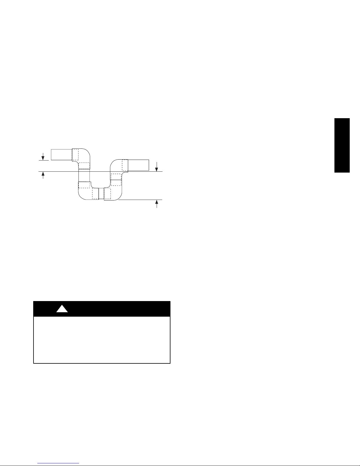
Step 6 — Connect Condensate Drain
NOTE: When installing condensate drain connection be sure to
comply with local codes and restrictions.
Model 574D----A disposes of condensate water through a 3/4 in.
NPT fitting which exits through the base on the evaporator coil
access side. See Fig. 2 and 3 for location.
Condensate water can be drained directly onto the roof in rooftop
installations (where permitted) or onto a gravel apron in ground
level installations. Install a field--supplied 2--in. (51 mm)
condensate trap at the end of condensate connection to ensure
proper drainage. Make sure that the outlet of the trap is at least 1 in.
(25 mm) lower than the drain--pan condensate connection to
prevent the pan from overflowing (See Fig. 7). Prime the trap with
water. When using a gravel apron, make sure it slopes away from
the unit.
Connect a drain tube using a minimum of 3/4--in. PVC or 3/4--in.
copper pipe (all field--supplied) at the outlet end of the 2--in. (51
mm) trap. Do not undersize the tube. Pitch the drain tube
downward at a slope of at least 1--in. (25 mm) for every 10 ft (3.1
m) of horizontal run. Be sure to check the drain tube for leaks.
TRAP
OUTLET
1-in. (25 mm) min.
2-in. (51 mm) min.
A09052
Fig. 7 -- Condensate Trap
Step 7 — Install Flue Hood
The flue assembly is secured and shipped in the return air duct.
Remove duct cover to locate the assembly (See Fig. 9).
NOTE: Dedicated low NOx models MUST be installed in
California Air Quality Management Districts where a Low NOx
rule exists.
These models meet the California maximum oxides of nitrogen
(NOx) emissions requirements of 40 nanograms/joule or less as
shipped from the factory.
NOTE: Low NOx requirements apply only to natural gas
installations.
!
WARNING
CARBON MONOXIDE POISONING HAZARD
Failure to follow this warning could result in personal
injury or death.
The venting system is designed to ensure proper venting.
The flue hood assembly must be installed as indicted in this
section of the unit installation instructions.
Install the flue hood as follows:
1. This installation must conform with local building codes
and with NFPA 54/ANSI Z223.1 National Fuel Gas Code
(NFGC), (in Canada, CAN/CGA B149.1, and B149.2)
latest revision. Refer to Provincial and local plumbing or
wastewater codes and other applicable local codes.
2. Remove flue hood from shipping location (inside the return
section of the blower compartment--see Fig. 9). Remove the
return duct cover to locate the flue hood. Place flue hood
assembly over flue panel. Orient screw holes in flue hood
with holes in the flue panel.
3. Secure flue hood to flue panel by inserting a single screw on
the top flange and the bottom flange of the hood.
Step 8 — Install Gas Piping
The gas supply pipe enters the unit through the access hole
provided. The gas connection to the unit is made to the 1/2--in.
(12.7 mm) FPT gas inlet on the gas valve.
Install a gas supply line that runs to the heating section. Refer to
the NFGC for gas pipe sizing. Do not use cast--iron pipe. It is
recommended that a black iron pipe is used. Check the local utility
for recommendations concerning existing lines. Size gas supply
piping for 0.5 IN. W.C. maximum pressure drop. Never use pipe
smaller than the 1/2--in. (12.7 mm) FPT gas inlet on the unit gas
valve.
For natural gas applications, the gas pressure at unit gas connection
must not be less than 4.0 in. wc or greater than 13 in. wc while the
unit is operating. For propane applications, the gas pressure must
not be less than 11.0 IN. W.C. or greater than 13 IN. W .C. at the
unit connection.
A 1/8--in. (3.2 mm) NPT plugged tapping, accessible for test gauge
connection, must be installed immediately upstream of the gas
supply connection to the gas valve.
When installing the gas supply line, observe local codes pertaining
to gas pipe installations. Refer to the NFPA 54/ANSI Z223.1 latest
edition (in Canada, CAN/CGA B149.1).
NOTE: In the state of Massachusetts:
1. Gas supply connections MUST be performed by a licensed
plumber or gas fitter.
2. When flexible connectors are used, the maximum length
shall not exceed 36 in. (915 mm).
3. When lever handle type manual equipment shutoff valves
are used, they shall be T--handle valves.
4. The use of copper tubing for gas piping is NOT approved
by the state of Massachusetts.
In the absence of local building codes, adhere to the following
pertinent recommendations:
1. Avoid low spots in long runs of pipe. Grade all pipe 1/4 in.
(6.35 mm) for every 15 ft (4.6 m) of length to prevent traps.
Grade all horizontal runs downward to risers. Use risers to
connect to heating section and to meter.
2. Protect all segments of piping system against physical and
thermal damage. Support all piping with appropriate straps,
hangers, etc. Use a minimum of one hanger every 6 ft (1.8
m). For pipe sizes larger than 1/2 in., follow
recommendations of national codes.
3. Apply joint compound (pipe dope) sparingly and only to
male threads of joint when making pipe connections. Use
only pipe dope that is resistant to action of liquefied
petroleum gases as specified by local and/or national codes.
Never use Teflon tape.
4. Install sediment trap in riser leading to heating section (See
Fig. 8). This drip leg functions as a trap for dirt and
condensate.
5. Install an accessible, external, manual main shutoff valve in
gas supply pipe within 6 ft (1.8 m) of heating section.
6. Install ground--joint union close to heating section between
unit manual shutoff and external manual main shut--off
valve.
7. Pressure test all gas piping in accordance with local and
national plumbing and gas codes before connecting piping
to unit.
574D-- --A
9
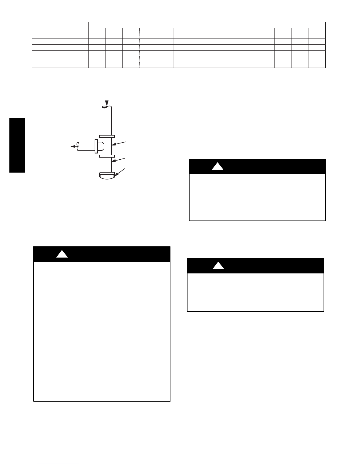
Table 2 – Maximum Gas Flow Capacity*
NOMINAL
IRON PIPE
SIZE (IN.)
1/2 .622 175 120 97 82 73 66 61 57 53 50 44 40 — —
3/4 .824 360 250 200 170 151 138 125 118 110 103 93 84 77 72
1 1.049 680 465 375 320 285 260 240 220 205 195 175 160 145 135
1 --- 1 / 4 1.380 1400 950 770 600 580 530 490 460 430 400 360 325 300 280
1 --- 1 / 2 1.610 2100 1460 1180 990 900 810 750 690 650 620 550 500 460 430
*Capacity of pipe in cu ft of gas per hr for gas pressure of 0.5 psig or less. Pressure drop of 0.5 ---IN. W.C. (based on a 0.60 specific gravity gas). Refer to Table
2 and National Fuel Gas Code NFPA 54/ANSI Z223.1.
{ This length includes an ordinary number of fittings.
INTERNAL
DIAMETER
(IN.)
10
(3)20(6)30(9)40(12)50(15)60(18)70(21)80(24)90(27)
LENGTH OF PIPE FT (m)†
100
(30)
125
(38)
150
(46)
175
(53)
200
(61)
IN
OUT
574D-- --A
TEE
NIPPLE
CAP
Fig. 8 -- Sediment Trap
NOTE: Pressure test the gas supply system after the gas supply
piping is connected to the gas valve. The supply piping must be
disconnected from the gas valve during the testing of the piping
systems when test pressure is in excess of 0.5 psig. Pressure test the
gas supply piping system at pressures equal to or less than 0.5 psig.
The unit heating section must be isolated from the gas piping
system by closing the external main manual shutoff valve and
slightly opening the ground--joint union.
!
WARNING
FIRE OR EXPLOSION HAZARD
Failure to follow this warning could result in personal injury,
death and/or property damage.
--Connect gas pipe to unit using a backup wrench to avoid
damaging gas controls.
--Never purge a gas line into a combustion chamber. Never
test for gas leaks with an open flame. Use a commercially
available soap solution made specifically for the detection of
leaks to check all connections.
--Use proper length of pipe to avoid stress on gas control
manifold.
--If a flexible connector is required or allowed by authority
having jurisdiction, black iron pipe shall be installed at
furnace gas valve and extend a minimum of 2 in. (51 mm)
outside furnace casing.
--If codes allow a flexible connector, always use a new
connector. do not use a connector which has previously
serviced another gas appliance.
C99020
8. Check for gas leaks at the field--installed and
factory --installed gas lines after all piping connections have
been completed. Use a commercially available soap solution
(or method specified by local codes and/or regulations).
Step 9 — Install Duct Connections
The unit has duct flanges on the supply-- and return--air openings
on the side and bottom of the unit. For downshot applications, the
ductwork connects to the roof curb (See Fig. 2 and 3 for
connection sizes and locations).
Configuring Units for Downflow (V ertical) Discharge
!
WARNING
ELECTRICAL SHOCK HAZARD
Failure to follow this warning could result in personal
injury or death.
Before installing or servicing system, always turn off main
power to system and install lockout tag. There may be
more than one disconnect switch.
1. Open all electrical disconnects before starting any service
work.
2. Remove horizontal (metal) duct covers to access vertical
(downflow) discharge duct knockouts in unit basepan.
!
PROPERTY DAMAGE HAZARD
Failure to follow this caution may result in property damage.
Collect ALL screws that were removed. Do not leave screws
on rooftop as permanent damage to the roof may occur.
To remove downflow return and supply knockout covers, break
front and right side connections tabs with a screwdriver and
hammer. Push cover down to break rear and left side tabs.
NOTE: These panels are held in place with tabs similar to an
electrical knockout. Reinstall horizontal duct covers (Fig. 9)
shipped on unit from factory. Insure openings are air and
watertight.
NOTE: The design and installation of the duct system must be in
accordance with the standards of the NFPA for installation of
nonresidence-- type air conditioning and ventilating systems, NFPA
90A or residence--type, NFPA 90B; and/or local codes and
ordinances.
CAUTION
10

Horizontal Duct Covers
A09061
Basepan
Downflow
(Vertical)
Supply
Knockout
Fig. 9 -- Supply and Return Duct Opening
Adhere to the following criteria when selecting, sizing, and
installing the duct system:
1. Units are shipped for horizontal duct installation (by
removing duct covers).
2. Select and size ductwork, supply--air registers, and
return--air grilles according to American Society of Heating,
Refrigeration and Air Conditioning Engineers (ASHRAE)
recommendations.
3. Use flexible transition between rigid ductwork and unit to
prevent transmission of vibration. The transition may be
screwed or bolted to duct flanges. Use suitable gaskets to
ensure weather--tight and airtight seal.
4. All units must have field--supplied filters or accessory filter
rack installed in the return--air side of the unit.
Recommended sizes for filters are shown in Table 1.
5. Size all ductwork for maximum required airflow (either
heating or cooling) for unit being installed. Avoid abrupt
duct size increases or decreases or performance may be
affected.
6. Adequately insulate and weatherproof all ductwork located
outdoors. Insulate ducts passing through unconditioned
space, and use vapor barrier in accordance with latest issue
of Sheet Metal and Air Conditioning Contractors National
Association (SMACNA) and Air Conditioning Contractors
of America (ACCA) minimum installation standards for
heating and air conditioning systems. Secure all ducts to
building structure.
7. Flash, weatherproof, and vibration isolate all openings in
building structure in accordance with local codes and good
building practices.
Basepan
Downflow
(Vertical)
Return
Knockout
A09060
Step 10 — Install Electrical Connections
!
WARNING
ELECTRICAL SHOCK HAZARD
Failure to follow this warning could result in personal
injury or death.
The unit cabinet must have an uninterrupted, unbroken
electrical ground. This ground may consist of an electrical
wire connected to the unit ground screw in the control
compartment, or conduit approved for electrical ground
when installed in accordance with NFPA 70 (NEC) (latest
edition) (in Canada, Canadian Electrical Code CSA C22.1)
and local electrical codes.
!
UNIT COMPONENT DAMAGE HAZARD
Failure to follow this caution may result in damage to the
unit being installed.
1. Make all electrical connections in accordance with NFPA
70 (NEC) (latest edition) and local electrical codes
governing such wiring. In Canada, all electrical
connections must be in accordance with CSA standard
C22.1 Canadian Electrical Code Part 1 and applicable
local codes. Refer to unit wiring diagram.
2. Use only copper conductor for connections between
field-- supplied electrical disconnect switch and unit. DO
NOT USE ALUMINUM WIRE.
3. Be sure that high--voltage power to unit is within
operating voltage range indicated on unit rating plate. On
3-- phase units, ensure phases are balanced within 2
percent. Consult local power company for correction of
improper voltage and/or phase imbalance.
4. Insulate low--voltage wires for highest voltage contained
within conduit when low-- voltage control wires are in
same conduit as high--voltage wires.
5. Do not damage internal components when drilling
through any panel to mount electrical hardware, conduit,
etc.
High--Voltage Connections
When routing power leads into unit, use only copper wire between
disconnect and unit. The high voltage leads should be in a conduit
until they enter the duct panel; conduit termination at the duct
panel must be watertight.
The unit must have a separate electrical service with a
field-- supplied, waterproof disconnect switch mounted at, or within
sight from, the unit. Refer to the unit rating plate, NEC and local
codes for maximum fuse/circuit breaker size and minimum circuit
amps (ampacity) for wire sizing.
The field-- supplied disconnect switch box may be mounted on the
unit over the high--voltage inlet hole when the standard power and
low--voltage entry points are used (See Fig. 2 and 3 for acceptable
location).
NOTE: Field supplied disconnect switch box should be
positioned so that it does not cover up any of the unit gas
combustion supply air louvers.
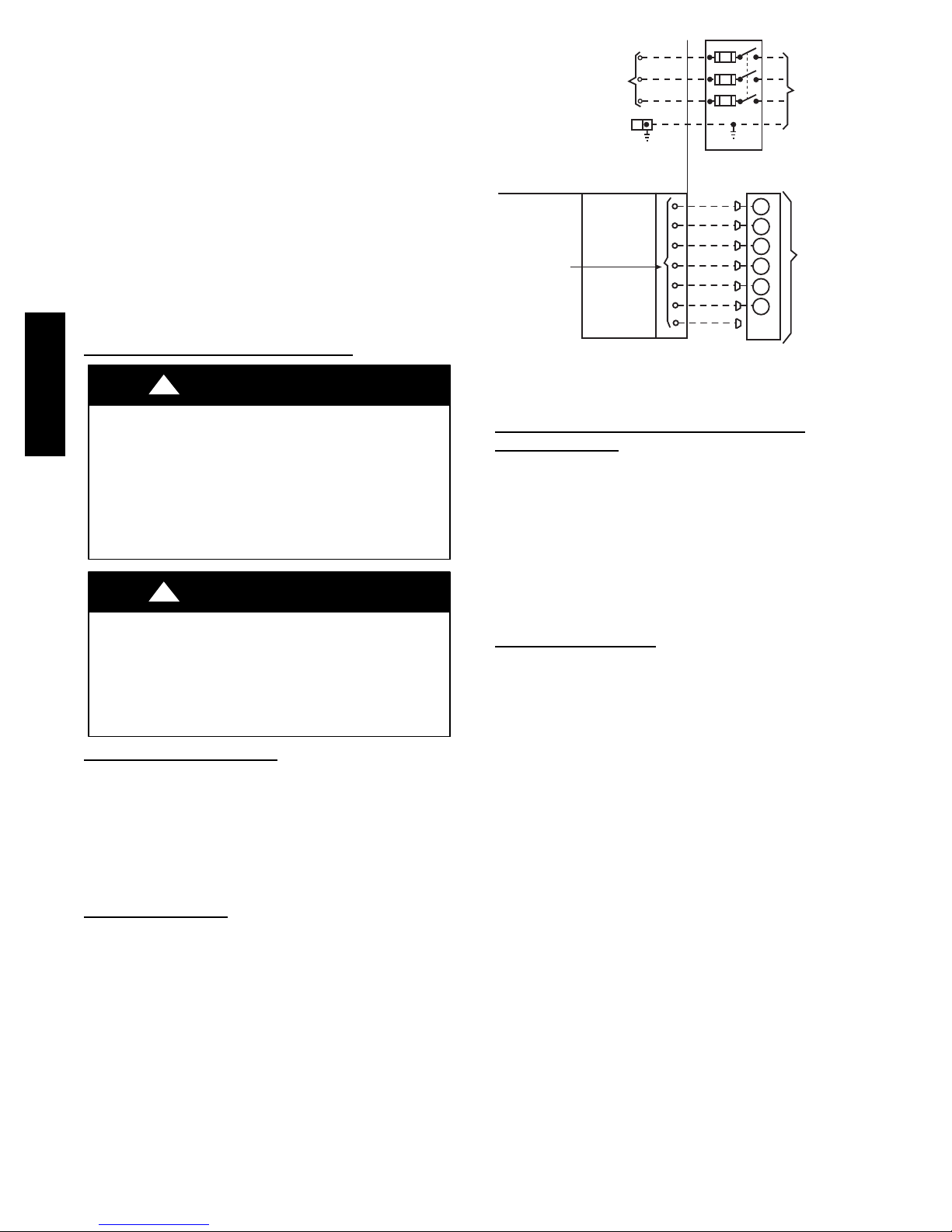
See unit wiring label (Fig. 14-- 16) and Fig. 10 for reference when
making high voltage connections. Proceed as follows to complete
the high--voltage connections to the unit.
Single phase units:
1. Run the high--voltage (L1, L2) and ground lead into the
control box.
CAUTION
574D-- --A
11
2. Connect ground lead to chassis ground connection.
3. Locate the black and yellow wires connected to the line side
of the contactor (if equipped).
4. Connect field L1 to black wire on connection 11 of the
compressor contactor.
5.ConnectfieldwireL2toyellowwireonconnection23of
the compressor contactor.
Three--phase units:
1. Run the high--voltage (L1, L2, L3) and ground lead into the
control box.
2. Connect ground lead to chassis ground connection.
3. Locate the black and yellow wires connected to the line side
of the contactor (if equipped).
4. Connect field L1 to black wire on connection 11 of the
compressor contactor.
5.ConnectfieldwireL3toyellowwireonconnection13of
the compressor contactor.
6. Connect field wire L2 to blue wire from compressor.
Special Procedures for 208--v Operation
!
WARNING
574D-- --A
ELECTRICAL SHOCK HAZARD
Failure to follow this warning could result in personal
injury or death.
Make sure the power supply to the unit is switched OFF and
install lockout tag. before making any wiring changes. With
disconnect switch open, move black wire from transformer
(3/16 in. [4.8 mm]) terminal marked 230 to terminal marked
208. This retaps transformer to primary voltage of 208 vac.
!
WARNING
ELECTRICAL SHOCK FIRE/EXPLOSION HAZARD
Failure to follow this warning could result in personal
injury or death and property damage.
Before making any wiring changes, mak e sure the gas
supply is switched off first. Then switch off the power
supply to the unit and install lockout tag.
HIGH VOLTAGE
POWER LEADS
(SEE UNIT WIRING
LABEL
3-PHASE SHOWN
1-PHASE USES
TWO POWER
LEADS
CONTROL BOX
LOW-VOLTAGE
POWER LEADS
(SEE UNIT
WIRING LABEL)
)
SPLICE BOX
EQUIP GR
FIELD-SUPPLIED
FUSED DISCONNECT
WHT(W1)
YEL(Y)
GRN(G)
RED(R)
BRN(C)
BLU(DH)
GRA(Y2)
3-Phase
Only
W
Y
G
R
C
DH
POWER
SUPPLY
THERMOSTAT
(TYPICAL)
A09053
Fig. 10 -- High-- and Control-- Voltage Connections
Heat Anticipator Setting (Electro--Mechanical
Thermostats
The room thermostat heat anticipator must be properly adjusted to
ensure proper heating performance. Set the heat anticipator, using
an ammeter between the W and R terminals to determine the exact
required setting.
NOTE: For thermostat selection purposes, use 0.18 amp for the
approximate required setting. Failure to make a proper heat
anticipator adjustment will result in improper operation, discomfort
to the occupants of the conditioned space, and inefficient energy
utilization; however, the required setting may be changed slightly
to provide a greater degree of comfort for a particular installation.
only)
Transformer Protection
The transformer is of the energy--limiting type, however a direct
short will likely blow a secondary fuse. If an overload or short is
present, correct overload condition and check for blown fuse on
Indoor Fan board or Integrated Gas Controller. Replace fuse as
required with correct size and rating.
Control Voltage Connections
Do not use any type of power--stealing thermostat. Unit control
problems may result.
Use no. 18 American Wire Gage (AWG) color--coded, insulated
(35_C minimum) wires to make the control voltage connections
between the thermostat and the unit. If the thermostat is located
more than 100 ft (30.5 m) from the unit (as measured along the
control voltage wires), use no. 16 AWG color--coded, insulated
(35_C minimum) wires.
Standard Connection
Run the low--voltage leads from the thermostat, through the inlet
hole, and into unit low--voltage splice box.
Locate six (seven for 3--phase) 18 --gage wires leaving control box.
These low--voltage connection leads can be identified by the colors
red, green, yellow, brown, blue, and white (See Fig. 10). A gray
wire is standard on 3--phase units for connection to an economizer.
Ensure the leads are long enough to be routed into the low--voltage
splice box (located below right side of control box). Route leads
through hole in bottom of control box and make low--voltage
connections (See Fig. 10). Secure all cut wires, so that they do not
interfere with operation of unit.
12
PRE--START--UP
!
WARNING
ENVIRONMENTAL, FIRE, EXPLOSION,
ELECTRICAL SHOCK HAZARD
Failure to follow this warning could result in personal
injury or death.
1. Follow recognized safety practices and wear protective
goggles when checking or servicing refrigerant system.
2. Do not operate compressor or provide any electric power
to unit unless compressor plug is in place and secured.
3. Do not remove ccompressor plug until all electrical
sources are disconnected and tagged.
4. Relieve and recover all refrigerant from system before
touching or disturbing compressor plug if refrigerant
leak is suspected around compressor terminals.
5. Never attempt to repair soldered connection while
refrigerant system is under pressure.
6. Do not use torch to remove any component. System
contains oil and refrigerant under pressure.
To remove a component, wear protective goggles and
proceed as follows:
a. Shut off electrical power to unit and install
lockout tag.
b. Relieve and reclaim all refrigerant from system
using both high-- and low--pressure ports.
c. Cut component connecting tubing with tubing
cutter and remove component from unit.
d. Carefully unsweat remaining tubing stubs when
necessary. Oil can ignite when exposed to torch
flame.
Use the Start--Up Checklist supplied at the end of this book and
proceed as follows to inspect and prepare the unit for initial
start --up:
1. Remove access panels (see Fig. 19).
2. Read and follow instructions on all DANGER, WARNING,
CAUTION, and INFORMATION labels attached to, or
shipped with unit.
3. Make the following inspections:
a. Inspect for shipping and handling damage, such as
broken lines, loose parts, disconnected wires, etc.
b. Inspect for oil at all refrigerant tubing connections and
on unit base. Detecting oil generally indicates a
refrigerant leak.
c. Leak--test all refrigerant tubing connections using
electronic leak detector, or liquid--soap solution. If a
refrigerant leak is detected, see following Check for
Refrigerant Leaks section.
d. Inspect all field-- and factory--wiring connections. Be
sure that connections are completed and tight.
e. Ensure wires do not touch refrigerant tubing or sharp
sheet metal edges.
f. Inspect coil fins. If damaged during shipping and
handling, carefully straighten fins with a fin comb.
!
WARNING
FIRE, EXPLOSION HAZARD
Failure to follow this warning could result in personal
injury, death or property damage.
Do not purge gas supply into the combustion chamber. Do
not use a match or other open flame to check for gas leaks.
Use a commercially available soap solution made
specifically for the detection of leaks to check all
connections.
4. Verify the following conditions:
a. Make sure gas line is free of air. Before lighting the unit
for the first time, perform the following with the gas
valve in the OFF position:
NOTE: If the gas supply pipe was not purged before connecting
the unit, it will be full of air. It is recommended that the ground
joint union be loosened, and the supply line be allowed to purge
until the odor of gas is detected. Never purge gas lines into a
combustion chamber. Immediately upon detection of gas odor,
retighten the union. Allow 5 minutes to elapse, then light unit.
b. Ensure fan hub is positioned correctly with respect to
motor housing.
c. Make sure that air filter(s) is in place.
d. Make sure that condensate drain trap is filled with water
to ensure proper drainage.
e. Make sure that all tools and miscellaneous loose parts
have been removed.
START--UP
Step 1 — Check for Refrigerant Leaks
Proceed as follows to locate and repair a refrigerant leak and to
charge the unit:
1. Locate leak and make sure that refrigerant system pressure
has been relieved and reclaimed from both high -- and
low--pressure ports.
2. Repair leak following accepted practices.
NOTE: Install a filter drier whenever the system has been opened
for repair.
3. Add a small charge of Puron (R--410A) refrigerant vapor to
system and leak--test unit.
4. Recover refrigerant from refrigerant system and evacuate to
500 microns if no additional leaks are found.
5. Charge unit with Puron (R--410A) refrigerant, using an
accurate scale. Refer to unit rating plate for required charge.
Step 2 — Start-- up Heating and Make Adjustments
Complete the required procedures given in the Pre--Start--Up
section before starting the unit. Do not jumper any safety devices
when operating the unit. Make sure that burner orifices are
properly aligned. Unstable operation my occur when the burner
orifices in the manifold are misaligned.
Follow the lighting instructions on the heating section operation
label (located on the inside of the control access panel) to start the
heating section.
574D-- --A
13
NOTE: Make sure that gas supply has been purged, and that all
gas piping has been checked for leaks.
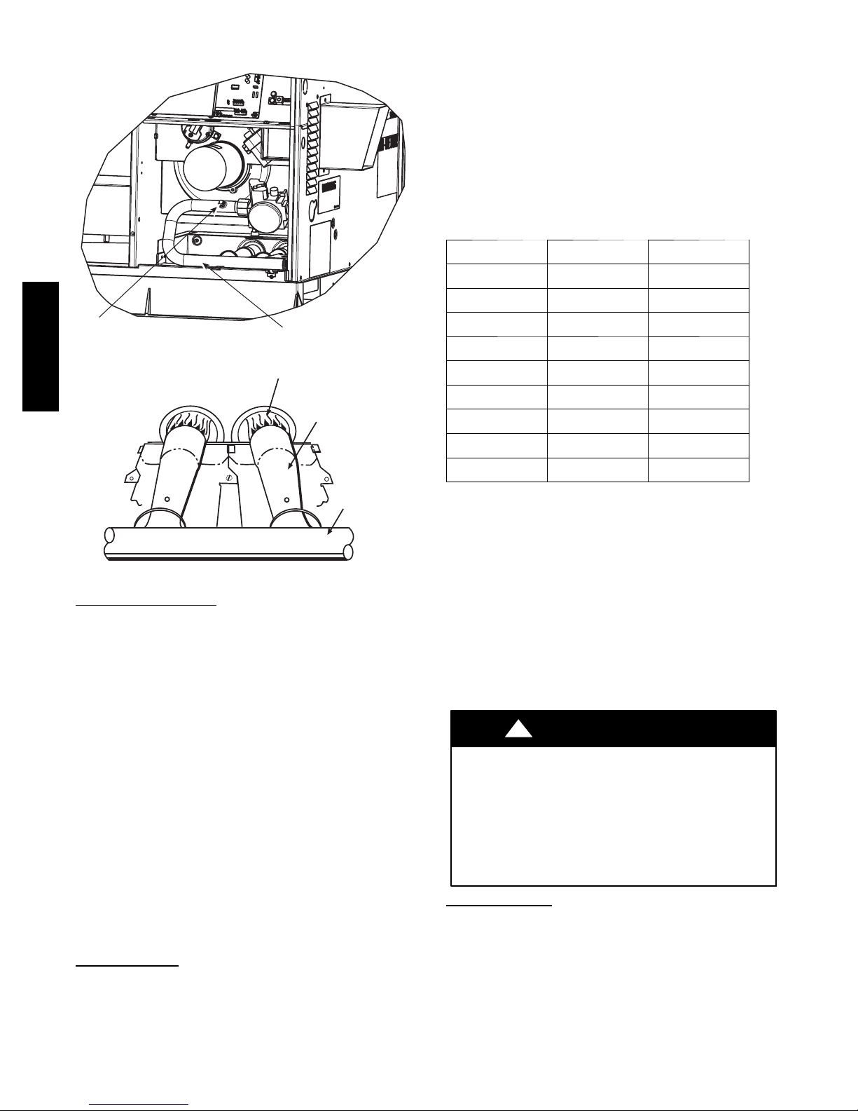
Pipe Plug
Manifold
Fig. 11 -- Burner Assembly
574D-- --A
BURNER FLAME
BURNER
MANIFOLD
Fig. 12 -- Monoport Burner
Check Heating Control
Start and check the unit for proper heating control operation as
follows (see furnace lighting instructions located on the inside of
the control access panel):
1. Place room thermostat SYSTEM switch in the HEAT
position and the fan switch is placed in AUTO position.
2. Set the heating temperature control of the thermostat above
room temperature.
3. The induced--draft motor will start.
4. On a call for heating, the main burner should light within 5
sec. of the spark being energized. If the burners do not light,
there is a 22 --sec. delay before another 5-- sec. try. If the
burners still do not light, this sequence is repeated. If the
burners do not light within 15 minutes from the initial call
for heat, there is a lockout. To reset the control, break the
24-- v power to W.
5. The evaporator fan will turn on 45 sec. after the flame has
been established. The evaporator fan will turn off 45 sec.
after the thermostat has been satisfied. Please note that the
integrated gas unit controller (IGC) has the capability to
automatically reduce the evaporator “ON” delay and increase the evaporator “OFF” delay in the event of high duct
static and/or partially--clogged filter.
Check Gas Input
Check gas input and manifold pressure after unit start --up (See
Table 4). If adjustment is required proceed as follows:
S The rated gas inputs shown in Table 4 are for altitudes from sea
level to 2000 ft (610 m) above sea level. These inputs are based
A07679
C99021
3
on natural gas with a heating value of 1025 Btu/ft
at 0.60
specific gravity, or propane gas with a heating value of 2500
3
at 1.5 specific gravity.
Btu/ft
IN THE U.S.A.:
The input rating for altitudes above 2,000 ft (610 m) must be
reduced by 4% for each 1,000 ft (305 m) above sea level.
For installations below 2,000 ft (610 m), refer to the unit rating
plate.
For installations above 2,000 ft (610 m). multiply the input by on
the rating plate by the derate multiplier in Table 3 for correct input
rate.
Table 3 – Altitude Derate Multiplier for U.S.A.*
ALTITUDE FT (M) PERCENT OF DERATE
0---2000
(0---610)
2001---3000*
(610---914)
3001---4000
(915---1219)
4001---5000
(1220---1524)
5001---6000
(1524 - -- 1829)
6001---7000
(1829---2134)
7001---8000
(2134---2438)
8001---9000
(2439---2743)
9001---10,000
(2744---3048)
*In Canada see Canadian Altitude Adjustment.
{Derate multiplier f actors are based on midpoint altitude for altitude range.
0 1.00
8 --- 1 2 0.90
12--- 16 0.86
16--- 20 0.82
20--- 24 0.78
24--- 28 0.74
28--- 32 0.70
32--- 36 0.66
36--- 40 0.62
DERATE MULTIPLIER
FACT OR{
IN CANADA:
The input rating for altitudes from 2,000 (610 m) to 4,500 ft (1372
m) above sea level must be derated 10% by an authorized Gas
Conversion Station or Dealer.
EXAMPLE:
90,000 Btu/hr Input Furnace Installed at 4300 ft.
Furnace Input Rate at
Sea Level
90,000 X 0.90 = 81,000
XDerateMultiplier
Facto r
= Furnace Input Rate at
Installation Altitude
When the gas supply being used has a different heating value or
specific gravity, refer to national and local codes, or contact your
distributor to determine the required orifice size.
!
CAUTION
UNIT DAMAGE HAZARD
Failure to follow this caution may result in reduced unit
and/or component life.
Do Not redrill an orifice. Improper drilling (burrs,
out--of--round holes, etc.) can cause excessive burner noise
and misdirection of burner flame. If orifice hole appears
damaged or it is suspected to have been redrilled, check
orifice hole with a numbered drill bit of correct size.
Adjust Gas Input
The gas input to the unit is determined by measuring the gas flow
at the meter or by measuring the manifold pressure. Measuring the
gas flow at the meter is recommended for natural gas units. The
manifold pressure must be measured to determine the input of
propane gas units.
Measure Gas Flow (Natural Gas Units)
Minor adjustment to the gas flow can be made by changing the
manifold pressure. The manifold pressure must be maintained
between 3.2 and 3.8 IN. W.C.
14
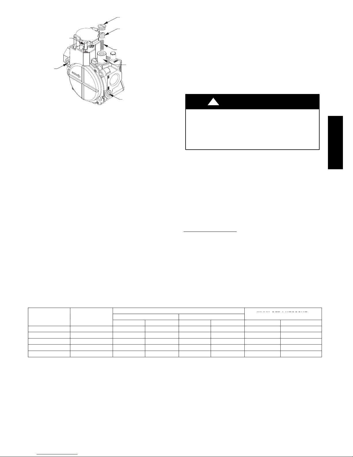
REGULATOR
NUMBER
OF
MANIFOLD
PRES
SURE
ORIFICES
COVER SCREW
PLASTIC
ADJUSTMENT
ON/OFF SWITCH
INLET
PRESSURE TAP
SCREW
REGULATOR SPRING
(PROPANE - WHITE)
(
NATURAL - SILVER)
GAS PRESSURE
REGULATOR
ADJUSTMENT
MANIFOLD
PRESSURE TAP
A07751
Fig. 13 -- Single--Stage Gas Valve
If larger adjustments are required, change main burner orifices
following the recommendations of national and local codes.
NOTE: All other appliances that use the same meter must be
turned off when gas flow is measured at the meter.
Proceed as follows:
1. Turn off gas supply to unit.
2. Remove pipe plug on manifold (See Fig. 11) and connect
manometer. Turn on gas supply to unit.
3. Record number of seconds for gas meter test dial to make
one revolution.
4. Divide number of seconds in Step 3 into 3600 (number of
seconds in one hr).
5. Multiply result of Step 4 by the number of cubic feet (cu ft)
shown for one revolution of test dial to obtain cubic feet (cu
ft) of gas flow per hour.
6. Multiply result of Step 5 by Btu heating value of gas to
obtain total measured input in Btuh. Compare this value
with heating input shown in Table 4 (Consult the local gas
supplier if the heating value of gas is not known).
EXAMPLE: Assume that the size of test dial is 1 cu ft, one
revolution takes 32 sec, and the heating value of the gas is 1050
3
. Proceed as follows:
Btu/ft
1. 32 sec. to complete one revolution.
2. 3600 ÷ 32 = 1.5.
3.112.5x1=112.5ft
3
of gas flow/hr.
4. 112.5 x 1050 = 118,125 Btuh input.
If the desired gas input is 115,000 Btuh, only a minor change in the
manifold pressure is required.
Observe manifold pressure and proceed as follows to adjust gas
input:
1. Remove regulator cover screw over plastic adjustment
screw on gas valve (See Fig. 13).
2. Turn plastic adjustment screw clockwise to increase gas
input, or turn plastic adjustment screw counterclockwise to
decrease input (See Fig. 13). Manifold pressure must be
between 3.2 and 3.8 IN. W.C.
!
WARNING
FIRE AND UNIT DAMAGE HAZARD
Failure to follow this warning could result in personal
injury or death and/or property damage.
Unsafe operation of the unit may result if manifold pressure
is outside this range.
3. Replace regulator cover screw on gas valve (See Fig. 13).
4. Turn off gas supply to unit. Remove manometer from
pressure tap and replace pipe plug on gas valve. (See Fig.
11.) Turn on gas to unit and check for leaks.
Measure Manifold Pressure (Propane Units)
Refer to propane kit installation instructions for properly checking
gas input.
NOTE: For installations below 2,000 ft (610 m), refer to the unit
rating plate for proper propane conversion kit. For installations
above 2,000 ft (610 m), contact your distributor for proper propane
conversion kit.
Check Burner Flame
With control access panel (see Fig. 19) removed, observe the unit
heating operation. Watch the burner flames to see if they are light
blue and soft in appearance, and that the flames are approximately
the same for each burner. Propane will have blue flame (See Fig.
13). Refer to the Maintenance section for information on burner
removal.
574D-- --A
HEATING INPUT
(BTUH)
40,000 2 4.0 13.0 11.0 13.0 3.2∼3.8 10.0∼11.0
60,000 2 4.0 13.0 11.0 13.0 3.2∼3.8 10.0∼11.0
90,000 3 4.0 13.0 11.0 13.0 3.2∼3.8 10.0∼11.0
115,000 3 4.0 13.0 11.0 13.0 3.2∼3.8 10.0∼11.0
130,000 3 4.0 13.0 11.0 13.0 3.2∼3.8 10.0∼11.0
*When a unit is converted to propane, different size orifices must be used. See separate, natural---to ---propane conversion kit in structions.
{Based on altitudes from sea level to 2000 ft (610 m) above sea level. In the U.S.A. for altitudes above 2000 ft (610 m), reduce input rating 4 percent for each
additional 1000 ft (305 m) above sea level. In C anada, from 2000 ft (610 m) a bove sea level to 4500 ft (1372 m) above sea level, derate the unit 10 percent.
Table 4 – Heating Inputs
GAS SUPPLY PRESSURE (IN. W.C.)
Natural{ Propane*{
Min Max Min Max Natural{ Propane*†
MANIFOLD PRESSURE
(IN. W.C.)
15
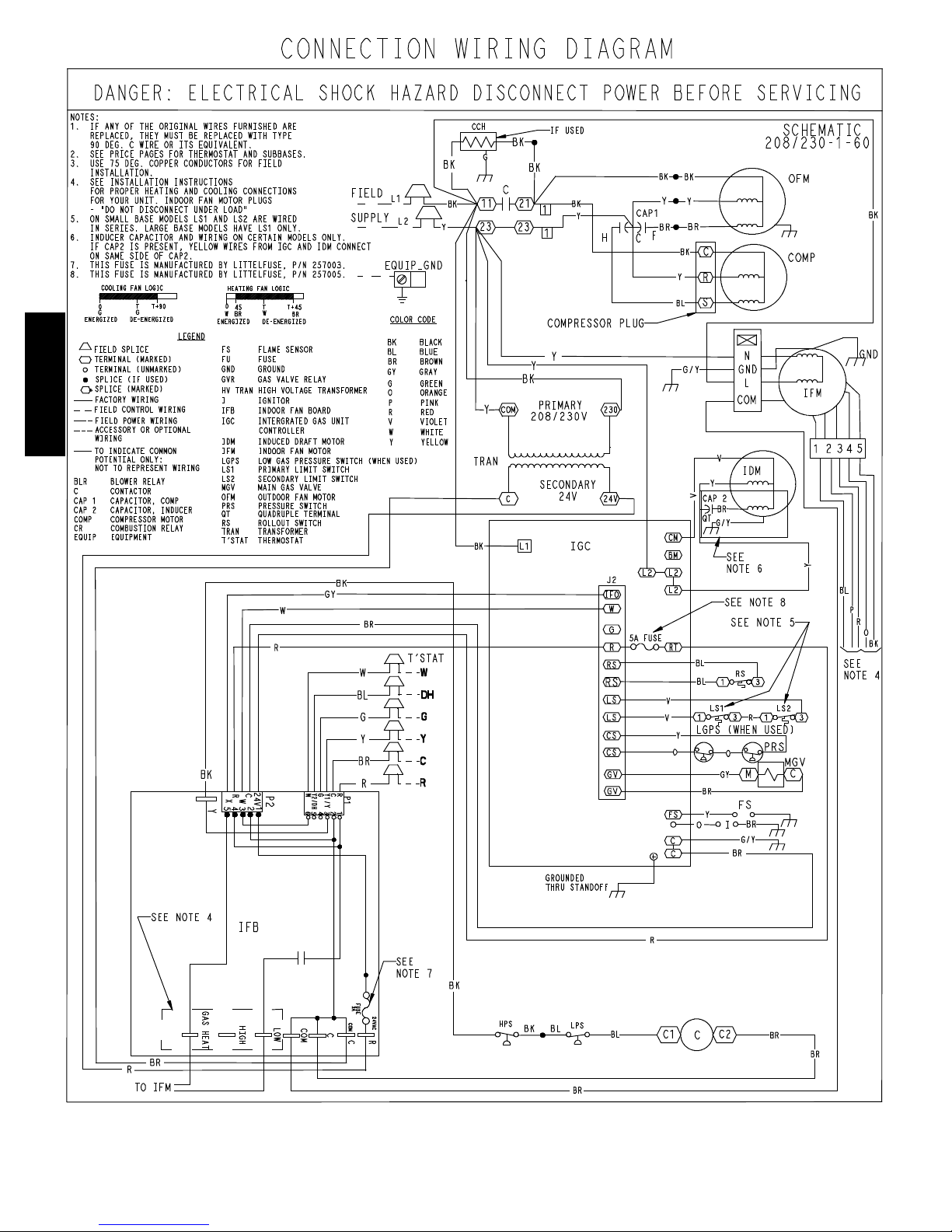
574D-- --A
A09282
Fig. 14 -- 208/230--1--60 Connection Wiring Diagram
16
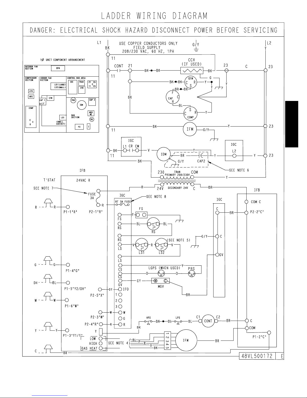
574D-- --A
Fig. 14 Cont. -- 208/230 --1--60 Ladder Wiring Diagram
A09282
17
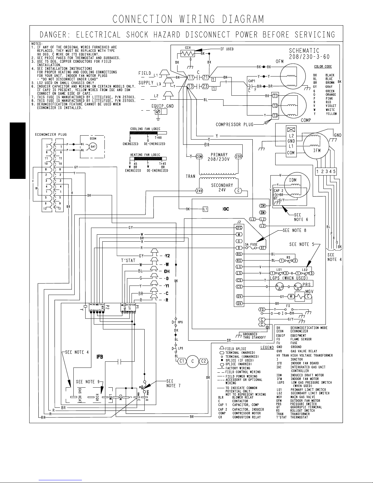
574D-- --A
A09264
Fig. 15 -- 208/230--3--60 Connection Wiring Diagram
18
 Loading...