

Page 1
Bryant
Airconditioning
Company
installation instructions
GAS-FIRED FORCED-
AIR FURNACE
39 4B &D
Series A
Sizes 050
thru 200
INTRODUCTION
Before installing the furnace, refer to “Procedure for
Gas Furnace Installation” (packaged with the equip
ment) for information concerning combustion, vent
ing, piping, and other standard installation practices.
Further reference is made to the current edition of the
American National Standard “Installation of Gas
Appliances and Gas Piping,” Z21.30.
Model 394 Gas Furnaces are shipped from the factory
completely assembled and wired ready for indoor
heating installation. They are manufactured with two
types of blowers: belt and direct drive. The four
smaller sizes, 50, 80, 100, and 125, are direct drive
only. All sizes incorporate a low-voltage terminal
strip for convenience of field wiring (except 50,000-
Btuh unit with complete shut-off gas controls.)
This publication covers installation, startup and
maintenance. For accessory installation details, refer
to applicable installation literature.
CAL’TTON: Do Tiot insrall hirnace in a coitosívp or
coiiTaminated almosphcre. Makp sure tliaV all local
ordinance's for coinbusTioii and circiilaTing air supply
are obser\ed.
Cancels: 39394D82
Figure 1—Modei 394D
39394DP85
11/1/74
A72548
The design of the 394B&D Upflow Gas-Fired Fur
naces is A.G.A. certified for installation on com
bustible flooring in alcoves, basements, closets, or
utility rooms.
CLEARANCE REQUIREMENTS
(in inches)
Sides............................................................................1
Back.............................................................................0
Top of Plenum.............................................................1
Vent Connector (single wall)
Type B (double wall)...............................................1
Front........................................................................ ..6
Provide service clearance of 30 in. at front of unit.
Bryant Automatic Gas Controi Vaive
NOTE: On units equipped with an A-643 Bryant
automatic gas control valve, there are three positions
for the manual valve knob (OFF-PILOT-ON). There
is a position stop at the PILOT position. To move the
manual valve knob from the PILOT position to either
ON or OFF position, the manual valve knob must be
depressed.
......................................
6
If not already checked when lighting the main burn
er, check the proper operation of this valve by
moving the room thermostat pointer above and below
room temperature and observing that the main burn
ers light on call for heat and go off when the pointer
is moved below the room temperature setting. All
Bryant automatic gas control valves have a delay
when opening or closing.
Fan/Limit Control Operation
At the moment the thermostat calls for heat, the time
delay mechanism of the control is energized. If, due to
pilot outage, the control bimetal element does not
sense a temperature change, the control will turn on
the blower strictly by means of the time delay feature.
If for any reason the time delay is not energized as the
thermostat calls for heat, the control bimetal element
will bring on the blower when it senses a temperature
rise of 50 degrees Fahrenheit (standard differential)
above the turn-off setting. During the blow-down
period and after the thermostat is satisfied, the con
trol will turn the blower off at the indicated setting
sensed by the control bimetal element.
Page 2
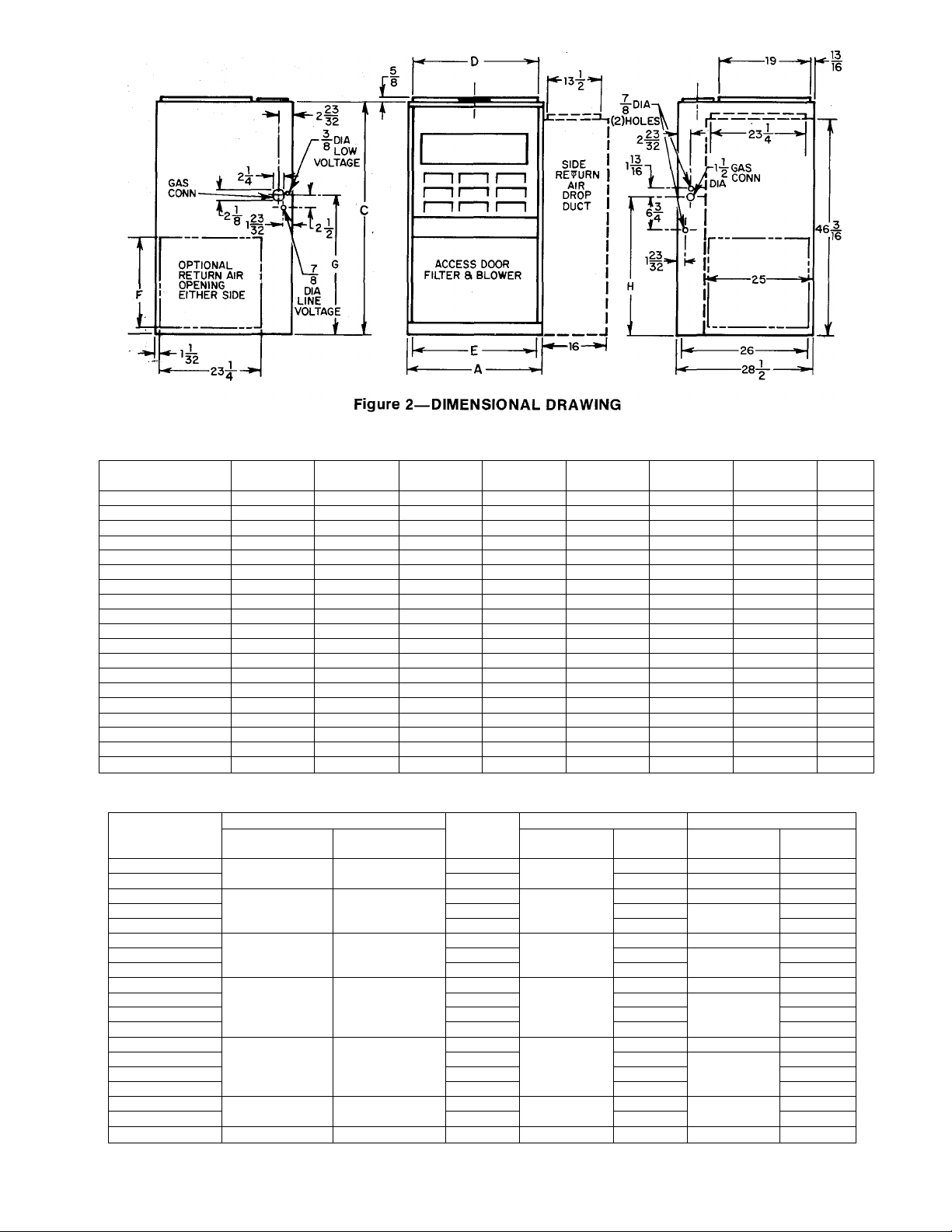
TABLE I—DIMENSIONS IN INCHES
MODEL & SIZE A
394D-000050
3940-024050
394D-000080
14-3/16 46-3/16
12
12
C
46-3/16
46-3/16 10-3/8 9-1/2 14-1/2 27-1/8
394D-024080 14-3/16 46-3/16
3940-036080 14-3/16 46-3/16 12-9/16
394D-000100
394D-036100
3940-048100
394D-000125
394D-036125
394D-048125
394D-060125
394D-000150
3940-048150
394D-060150
394B-060150
394D-060175
394B-060175
394B-060200
17-1/2 46-3/16
17-1/2
46-3/16 15-7/8 15 14-1/2 27-1/8
21 46-3/16
21
21
46-3/16
46-3/16
21 46-3/16
21
46-3/16 19-5/16 18-1/2 14-1/2 27-1/8
24-1/2 46-3/16
24-1/2 46-3/16
24-1/2
24-1/2
31-1/2
31-1/2
31-1/2
49 22-7/8 21 18 29-15/16
49 22-7/8 21 18 29-15/16
49 29-7/8 29 18 29-15/16
49 29-7/8 29 18 29-15/16
49 29-7/8 ' 29 18 29-15/16
D E F
10-3/8 9-1/2
14-1/2 27-1/8
12-9/16 11-11/16 14-1/2
12-9/16 11-11/16
11-11/16
15-7/8 15
19-5/16 18-1/2
19-5/16
19-5/16
19-5/16
18-1/2 14-1/2 27-1/8
18-1/2 14-1/2 27-1/8
18-1/2 14-1/2 27-1/8
14-1/2 27-1/8
14-1/2 27-1/8
14-1/2 27-1/8
14-1/2 27-1/8
G
27-1/8
22-7/8 21 14-1/2 27-1/8
22-7/8
21 14-1/2
27-1/8
H
32-9/16
32-9/16
32-9/16
32-9/16
32-9/16
32-9/16 5
32-9/16
32-9/16
32-9/16 5
32-9/16
32-9/16 5
32-9/16 5
32-9/16
32-9/16
35-3/8 6
35-3/8 6
35-3/8
35-3/8 7
35-3/8
TABLE II—RATINGS AND PERFORMANCE*
NATURAL and LP Temp
Rise
MODEL
394D-000050
3940-024050
394D-000080
394D-024080
3940-036080
394D-000100
394D-036100
Input Btuh
50,000
80,000
100,000
Output Btuh
40,000
64,000
80,000
Range
70-100
45-100
70-100
70-100
45-100
70-100
45-100
3940-048100 45-75
394D-000125
394D-036125
394D-048125
125,000 '
100,000
394D-060125
394D-000150
394D-048150
394D-060150
150,000
120,000
394B-060150
394D-060175
394B-060175
175,000
140,000
394B-060200 200,000 160,000
"The above ratings are certified for altitudes to 2000 ft. For elevations above 2000 ft. reduce ratings 4% for each 1000 ft. above sea
level.
70-100
70-100
45-100
45-75
70-100
45-100
45-75
45-100
45-100
45-100
70-100
Heating
Ext Static
Pressure
0.12
0.12
0.15
0.2
0.2
0.5
0.5 1634
Cooling
Ext Static
CFM
408
Pressure
—
482 0.5
654 —
772 0.5
772
818
—
965 0.5 1200
1157 1540
1020
—
1069
1206
0.5
1447
1225
— —
1454
1736
0.5
1447
1688
1688 2290
0.5
0.5 2460
A72591
Vent
Dia
4
4
4
4
4
5
5
5
6
6
7
7
CFM
—
780
—
790
1190
—
—
1210
1560
2000
1500
2080
2310
2010
—2-
Page 3
TO HEATING AND
COOLING CONNECTIONS
OF THERMOSTAT
_A
TO CONDENSER
CONTACTOR COIL
CONNECTIONS
TO HEATING AND
COOLING CONNECTIONS
OF THERMOSTAT
TO CONDENSER
LOW-VOLTAGE LEAD
OR TERMINAL STRIP
NOTE:
WIRE WITH * IN FIGURE 3 IS
REMOVED AND DISCARDED WHEN
CONDENSER HAS TRANSFORMER.
A73118
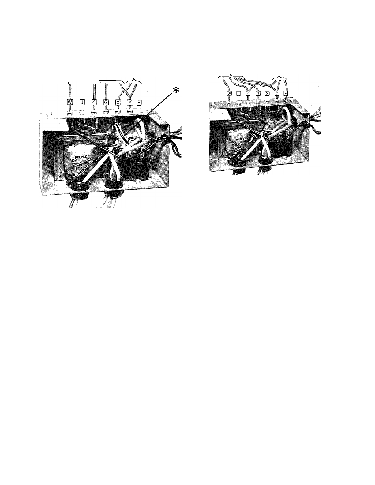
Figure 3—Control Box, Cover Removed,
No Internal Wiring Changes
The 175,000-Btuh belt-drive, and 200,000-Btuh units
are equipped with a Honeywell fan limit control. It
provides control of fan operation and high-limit tem
perature protection. The fan switch makes contact to
start the blower motor on temperature rise to set
point. The limit switch breaks the circuit to the burn
ers when the temperature rise reaches the set point.
Thermostat Location
The room thermostat should be located where it will
be in the natural circulating path of room air. Avoid
locations where the thermostat would be exposed to
cold air infiltration, drafts from windows, doors, or
other openings leading to the outside, or exposure to
air currents from warm or cold air registers; or to ex
posure where the natural circulation of the air is cut
off—such as behind doors, above or below mantels,
shelves, etc.
The thermostat should not be exposed to heat from
nearby fireplaces, radios, televisions, lamps, or rays
from the sun. Nor should the thermostat be mounted
on a wall containing pipes or warm air ducts, or a flue
or vent that could affect its operation and prevent it
from properly controlling the room temperature. Any
hole in the plaster or panel through which the wires
pass from the thermostat should be adequately sealed
with suitable material to prevent drafts from affecting
the thermostat.
Figure 4—Control Box, Cover Removed,
Showing Internal Wiring Changes
Set the thermostat heat anticipator at 0.5.
If additional controls are connected in the thermostat
circuit, the amp draw must be added to these settings.
Failure to make the settings will result in improper
operation of the thermostat.
ELECTRICAL CONNECTIONS
Low-Voltage Wiring
Field low-voltage connections are made at the low-
voltage terminal strip. See Figure 3. For Model 394
Furnaces used in conjunction with electric or gas air
conditioning units that do not have an integral trans
former, see Figure 3. If the 394 Furnace is used in con
junction with an electric or gas air conditioning unit
having an integral transformer, see Figure 4.
Figure 4 shows a field-installed wire running from
one side of the air conditioning transformer, through
the hole marked “F” in the terminal strip, to the
blower relay in the control box for the Model 394 Fur
nace. The wire marked * in Figure 3 is removed from
the control box and discarded.
NOTE: For heating-only connections, See Figure 8. For
heating and cooling connections, see Installation In
structions packaged with condensing unit.
—3—
Page 4
Line-Voltage Wiring
All electrical connections are to made in accor
dance with the local electrical codes. The unit must be
grounded electrically in accordance with National
Electric Code and local codes governing such in
stallations. A permanent and uninterrupted or un
broken ground is essential to minimizing personal in
jury if an electrical fault should occur. A permanent,
separately fused electric power supply, complete with
manual switch, should be provided for the furnace.
Field wiring connections should be made in accor
dance with the unit wiring diagrams.
When making aluminum conductor connections to
copper conductors or terminals, use only connectors
that are UL approved (marked Al/Cu with the UL
symbol) for the application and wire size. Do not
reduce wire size to fit connector by cutting off strands.
Use proper size connector.
After insulation has been stripped from the aluminum
conductor, coat the conductor end with corrosion
inhibitor (Burndy “Penetrox A” or equivalent), and
wire-brush the aluminum surface thru the inhibitor.
CAUTION: Do nor wire-brii.sh connectors atul lug.s.
The plating will be broken.
After cleaning, recoat the aluminum conductor with
inhibitor, and make connection, then coat entire con
nection. If applicable, wrap the connection for
moisture and/or electrical protection.
CAUTION: Re sure ihe filiej- relainiM- spring is
behind rile flange of the casing side.
When the side inlet is used, the bottom opening
should be properly and permanently sealed.
NOTE: Side inlet application of sizes 048100, 060125,
060150, 060175, and 060200 requires use of the ap
propriate optional external filter rack. See in
structions packed with filter rack for installation.
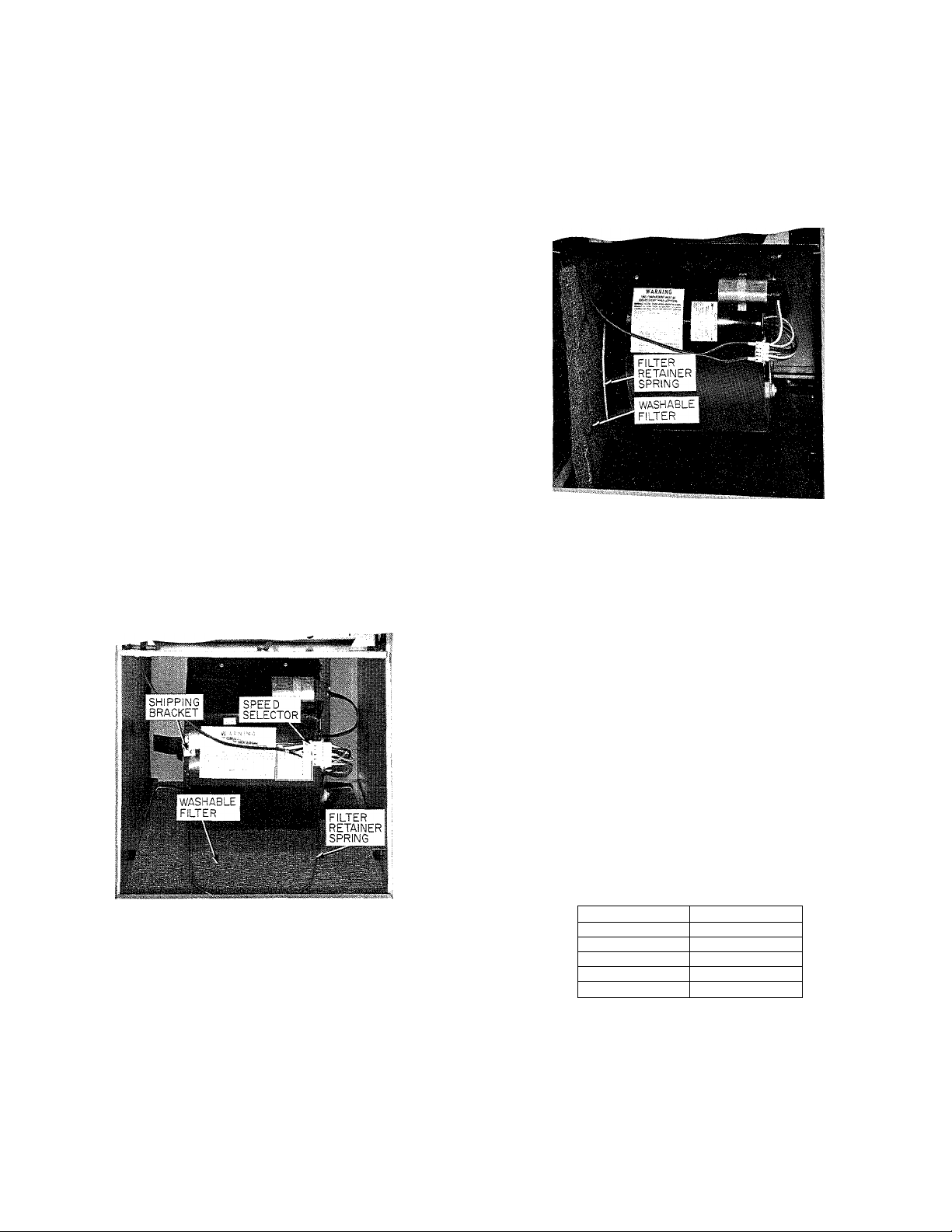
Figure 6—Filter installed For Side Inlet
NOTE: Some units with direct-drive blowers have a
shipping bracket. See Figure 5. This bracket should be
removed and discarded. Belt-drive units have wood
shipping blocks that are to be removed and discarded.
A73115
Figure 5—Filter Installed For Bottom Inlet
Filters
The filters are factory-installed in the bottom of the
furnace. This is for bottom inlet application. See
Figure 5.
For side inlet application, see Figure 2 and Table I
for the opening size. Remove the filter and the
retainer spring from the bottom opening. Install the
retainer spring in the holes provided, one in the
blower deck and the other in the retainer spring
bracket. See Figure 6.
STARTUP AND ADJUSTMENT
In addition to the following information, refer to
“Procedures for Gas Furnace Installation” packaged
with the unit.
Adjustment of Blower Speed
Four-Speed Direct Drive
To change motor speed taps, remove the motor tap
lead (see Figure 5) and relocate it on the desired ter
minal on the plug-in terminal block/speed selector
located on the blower.
TABLE III
SPEED SELECTOR
Speed
Common
Hi
Med-Hi
Med-Lo
Lo
Tap No.
C
1
2
3
4
Belt Drive
The blower speed may be changed by opening or
closing the motor pulley. When adjusting blower
speed, be certain that the pulleys are properly aligned.
CAUTION: When adjusting the blower speed, make
certain that the temperature rise across the bear ex
changer does not exceed that specified on ilie rating
plate.
Page 5
CARE AND MAINTENANCE
WARNING: Fiecaiise personal injury or damage to
the furnaee may result, maintuname should be perIbrmed by qualified persons only.
Care of Blower and Motor
For long life, economy, and high efficiency; clean ac
cumulated dirt and grease from blower wheel and
motor annually. Also clean around bearings and
shaft(s) of blower and motor. See label on blower for
oiling instructions.
Belt Tension
Adjust tension on a V-belt so that the helt deflects ap
proximately 3/4 to 1 inch when the pressure from one
finger is applied midway between the blower and
motor pulleys.
Filters
Each furnace is shipped with a washable permanent
filter. Check every 30 to 60 days. See label on blower
for cleaning method. It is not necessary to spray filter
with oil.
Cleaning Heat Exchanger
If it becomes necessary to clean heat exchanger—
because of carbon deposits, soot, etc.—shut off gas
and electricity. Remove burners and manifold assem
bly. Remove vent connector and draft diverter.
Remove flue baffles from upper heating element flue
outlets by removing two screws that secure Raffles in
place. Clean flueways with brush and/or vacuum.
Replace flue baffles and tighten screws carefully.
Replace draft diverter and vent connector. Replace
manifold and burners. Connect gas and electricity.
Test for gas leaks.
WARNING: Never use a maieh or otbor open Hanie
to eiiei’k for gas leaks. Use a sotip-aml-waier solution.
A73119
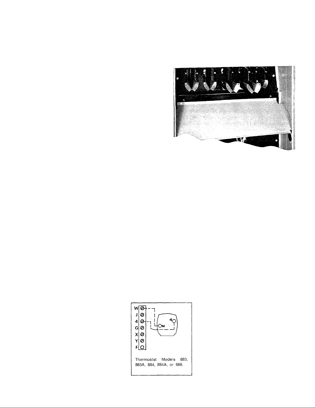
Figure 7—Removing Baffles
PILOT
Pilot should be checked and cleaned if necessary at
the beginning of each heating season. Pilot flame
should be high enough for proper impingement of the
safety element and to light the burners. Remove ac
cumulation of soot and carbon from thermocouple
safety element, if used.
It is recommended the pilot be turned off during the
summer season.
HEATING-ONLY THERMOSTAT CONNECTIONS
Figure 8—Field Wiring Connection
—5—
Page 6
LINE-TO-LINE WIRING DIAGRAMS
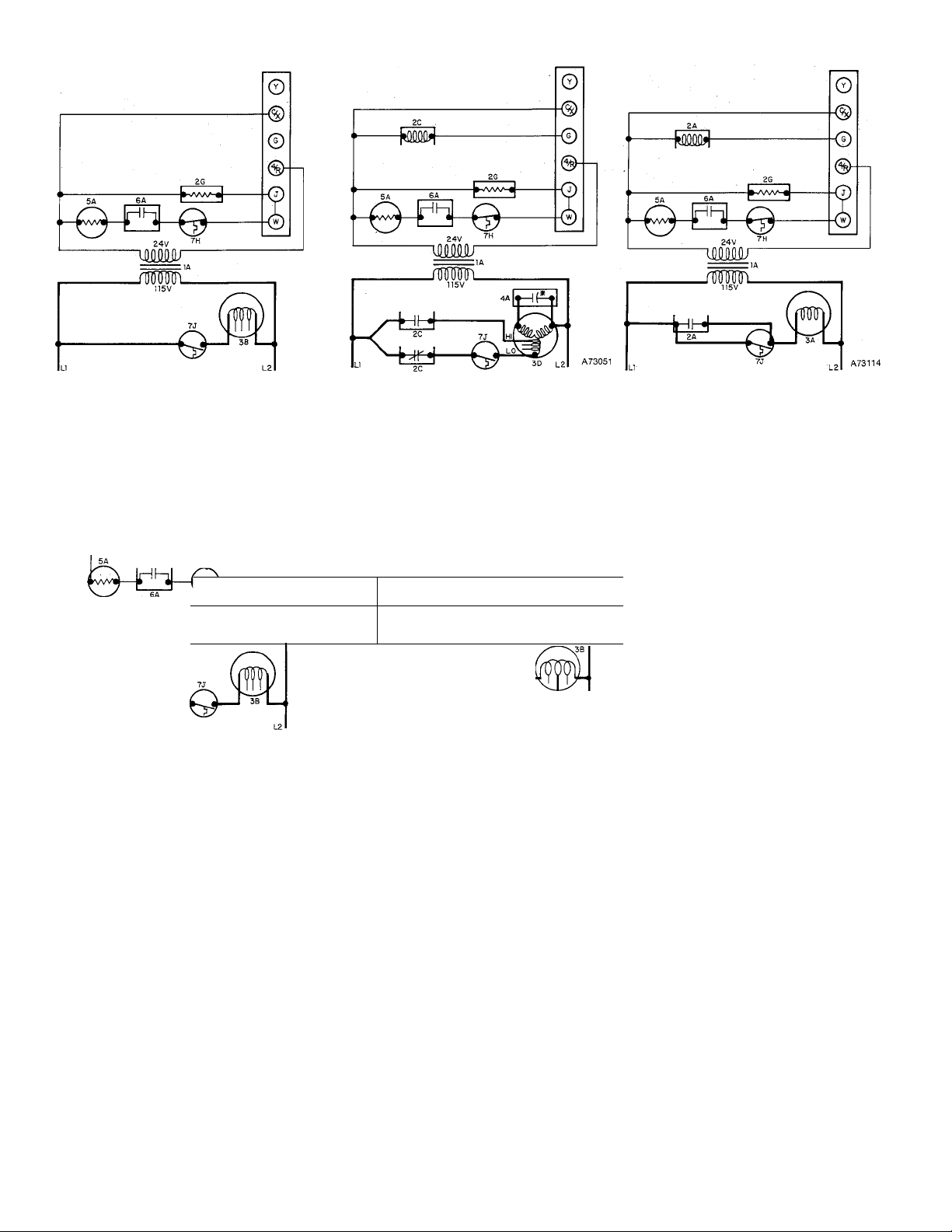
Figure 9 - Units with 1/10-, 1/6-, or 1/5-KP Direct-
Drive Motor (no cooling fan relay)
lA
H5V
____
jWM
Figure 12 - 50,000-Btuh Unit with B or D controls
(no cooling fan relay)
R
Figure 10 - Units with 1/6-, 1/3-, 1/2-, or 3/4-HP
________________________
A73053
Figure 13 - 50,000-Btuh Unit with B or D Controls
SEQUENCE OF OPERATION—HEATING
The pilot (6A) must be lit, closing its contacts, before
the gas valve (5A) will open. If, for some reason, the
gas valve does not open when thermostat calls for
heat, heat assist coil (2G) causes heating relay (7J) to
close its contacts, energizing blower motor (3A, 3B, or
3D).
When the thermostat calls for heat, the control circuit
is closed between terminals (4 and W). Power from
transformer (lA) energizes automatic gas valve coil
(5A) and heat assist coil (2G) simultaneously. After a
short time delay, automatic gas valve (5A) opens, per
mitting gas to flow to the burners where it is ignited
by the gas pilot. After another delay, the heating relay
switches its contacts (7J), energizing blower motor
(3A, 3B, or 3D) on heating speed.
When the thermostat is satisfied, the circuit between
terminals (4 and W) is broken, deenergizing
automatic gas valve coil (5A) and heat assist coil
(2G). After a few seconds, automatic gas valve (5A)
closes, stopping’the flow of gas to the burners. After a
Direct-Drive Motor (cooling fan relay).
No Capacitor on 1/6- and 1/3-HP
Motors.
—Mna4-
---------------------
íMüWu
■fciti-
24V
___
_________
fepi—©■
(cooling fan relay)
longer delay, heating relay (7J) opens its contacts to
stop blower motor (3A, 3B, or 3D).
If the furnace overheats for any reason, limit control
(7H) will switch, breaking the circuit to automatic gas
valve coil (5A). After a short delay, the gas valve
closes, shutting off the flow of gas to the burners.
The furnace will continue to cycle until the fault is
corrected.
SEQUENCE OF OPERATION—COOLING
When the thermostat calls for cooling, power from
transformer (lA) energizes cooling relay coil (2C),
closing its contacts, and energizing blower motor (3A,
3B, or 3D) on its cooling speed. It continues to operate
until the thermostat is satisfied.
When the thermostat is satisfied, the circuit to ter
minal (G) is broken, deenergizing cooling relay coil
(2C) which, in turn, opens its contacts, stopping
blower motor (3A, 3B, or 3D).
Figure 11 - Units with 3/4-HP Belt-Drive Motor
JE.
JiL
a
(cooling fan relay)
LEGEND
1 A-Transformer
2A-Cooling Fan Relay
2C-Cooling Fan Relay
2G-Fleatlng Fan Relay
3A-Fan Motor SP PH
3B-Fan Motor SP
3D-Fan Motor PSC
4A-Capacitor (None on 1/6-
& 1/3-HP Motors)
5A-Gas Valve
6A-Pllot (None on LP)
7J-Fan Control SPST N.O.
If any of the original wire, as supplied, must be
replaced, use same type or equivalent wire.
/
—6—
 Loading...