

Page 1

Installation Instructions
379A
Models
48W- & 60W-379A
Series C
OUTDOOR HE ATI N G UNIT
Bryant Models 48W-379A and 60W-379A are outdoor
heating units designed for installation on a rooftop or
at ground level. Both models have a chilled water coil
factory installed. Model 48W-379A is equipped with a
48.000 Btuh coil while Model 60W-379A is equipped
with a 60,000 Btuh coil.
These units were designed for use in split systems with
matching Bryant gas-fired water chillers. Both models
have 150,000 Btuh heating input rating and a 112,500
Btuh heating output rating. Model 48W-379A has a
48.000 Btuh cooling rating when connected to a
Bryant Model 48-453 Gas-Fired Water Chiller. Model
60W-379A has 60,000 Btuh cooling rating when con
nected to a matching Bryant Model 60-452 Gas-Fired
Water Chiller.
Important—Read before Installing
1. Check all local or other applicable codes for in
formation concerning proximity to property lines,
height above roof, obstructions, etc.
2. Be sure the power supply available (voltage,
frequency, and phase) corresponds to that specified
on the unit rating plate.
3. Check the electrical service provided by the utility
for the building to be sure that the service capacity is
sufficient to handle the load imposed by this unit.
4. Refer to the regulations of the serving gas supplier
and the local building, heating, plumbing, or other
codes in effect in the area in which installation is to
be made.
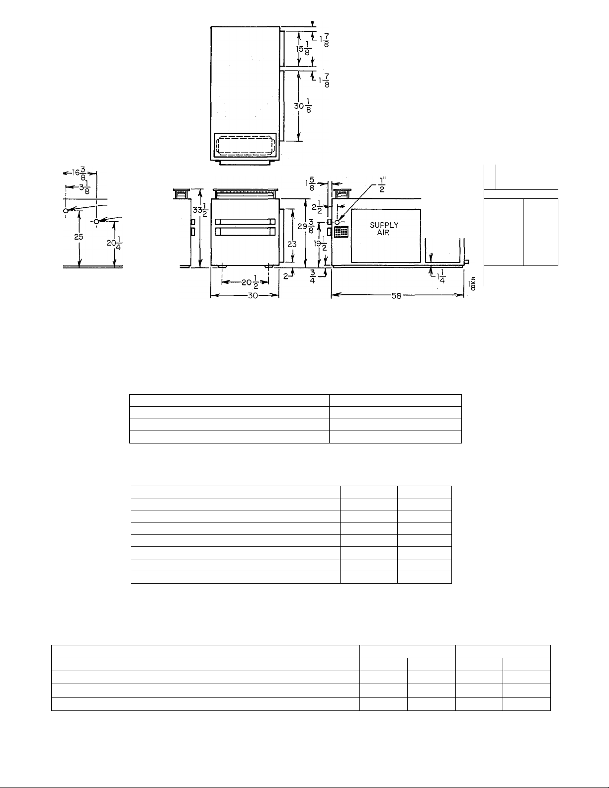
5. Refer to the dimensional drawing on page 2 for
location of electrical, gas, and chilled water con
nections prior to setting the unit in place.
GENERAL
The design of this unit is certified by A.G.A. for use
with natural or propane gases with appropriate con
trols and orifices. This unit is designed for outdoor in
stallation only.
Installation of the unit consists of the following:
I. Locating the Unit
II. Gas Piping
III. Duct Connections
IV. Venting
V. Coil Connections
VI. Electrical Connections
VII. Start-up and Adjustments
fariiant
39379D36
4/15/72
I
I i
L<-:
I.DO
’REMOVc- '
Figure 1—Model 48W-379A
In addition, the following section should be reviewed
by the equipment owner.
VIII. Maintenance
I. LOCATING THE UNIT
Extreme caution should be used when rigging and
moving the unit to prevent damage. The unit should
be kept upright during all rigging and moving
operations. To facilitate lifting and moving, place the
unit in an adequate sling made of rope or cable.
CAUTION: Be sure to protect the top and sides of the
unit from cable damage when rigging the unit to be
lifted.
Rooftop Installation
Level the unit on a base that is at least 6 inches above
the roof to provide drainage from beneath the unit.
Consult local codes for installation requirements. Be
sure that the roof will support the additional weight.
Ground Level Installation
If the unit is to be installed on the ground, it should
be placed on a level concrete slab with a minimum
thickness of 4 inches.
Page 2
LINE VOLTAGE
LOW VOLTAGE
LEFT SIDE
1 FP.T. WATER
CONNECTIONS-
GAS CONNECTION
FRONT RIGHT SIDE
Figure 2—Dimensional Drawing
RETURN
AIR
43
1
4 IH*'....................M
rIN
2
=16
23|
'
■H i
|0.D.
CONDENSATE DRAIN
REAR
A69163
TABLE 1 - HEATING
Model
Heating Input Btuh
Heating Output
Approved Temp Rise °F
Buth
CAPACITY
48W-379A & 60W-379A
150,000
112,500
45 - 75
TABLE II • «RATINGS AND PERFORMANCE
Model 48W-379A
Cooling Capacity
Airflow
External Static Pressure
Entering Air Temp
Entering Water Temp °F 45
Water Flow GPM
Water Pressure Drop Ft w.c. 18.1
Btuh 48,000
CFM
In. w.c. 0.43 0.52
°F 80DB/67WB 80DB/67WB
1600 2000
10
*Ratings given in Table II are for Model 48W-379A connected to a Model 48-453
Chiller and Model 60W-379A connected to a Model 60-452 Chiller.
60W-379A
60,000
TABLE III—ELECTRICAL CONNECTIONS
Model 48W-379A
Nameplate Voltage-Hertz-Phase
Unit Ampacity for Electrical Conductor Sizing
Min Branch Circuit Wire Size (75°C copper*) AWG
Max Branch Circuit Fuse Size Amps
Amps
208-60-1
6.2
14 14
15
45
12.5
9.8
230-60-1
4.9
15
60W-379A
208-60-1 230-60-1
8.6 6.9
14 14
15 15
*If other than 75°C copper is used, determine size from unit ampacity and the National Electric Code. Voltage drop of wire
selected must be less than 2% of unit rated voltage. Connections of aluminum wire must be in accordance with the National
Electric Code.
39379D36
-2
Page 3

NOTE: It is important that the unit be installed in a
level position.
Clearances
The rm'nimmn clearance is 6 inches from the duct
side, 24 inches on all other sides, and 0 inches on the
bottom. This permits the use of combustible materials
for supports.
CAUTION: When using rails, etc., as support, make
allowances for surface water drainage under the unit.
II. GAS PIPING
2. A separate gas supply line should be installed to
run directly from the meter to the furnace. Check your
local utility for recommendations concerning existing
lines. Choose a supply pipe sized large enough to keep
the pressure loss as low as practical.
CAUTION: Never use pipe smaller than the gas con
nection to the furnace. Observe local codes for all gas
pipe installations.
The following are pertinent recommendations:
1. Avoid low spots in long runs of pipe. It is best to
grade all pipe 1/4 inch in every 15 feet to prevent
traps. All horizontal runs should grade downward to
risers. Risers should be used to coimect to the furnace
and to the meter.
2. Install a drip leg in the riser leading to the furnace.
This drip leg will serve as a trap for dirt and con
densate. Drip legs should be installed where con
densate will not freeze. (See Figure 3 for drip leg
location.)
3. A manual shutoff valve should be installed in the
gas supply pipe near the furnace where it can be
easily reached.
4. Place a ground joint union close to the unit be
tween the gas controls manifold and the manual
shutoff valve.
5. Support all piping with appropriate hangers, etc.
The maximum distance between hangers should be 10
feet.
6. Joint compound (pipe dope) must be resistant to
the action of propane gas.
WARNING: Never use a match or other open flame
to check for gas leakage.
7. After all connections are made, check for leakage
by using soap-and-water solution (or in accordance
with local utility regulations).
III. DUCT CONNECTIONS
Before ductwork can be attached to the unit, remove
and discard the cover panel that is located over the
outlet and return air openings. The ductwork may be
screwed or bolted to the unit flange with suitable
gaskets to insure weathertight seal. Be sure that the
sheet metal overlaps the flange on the unit.
All ductwork external of the structure must be
properly insulated and waterproofed. All openings in
the structure must be properly flashed and vibrationisolated in accordance with local codes and good
building practices. The supply and return ductwork
should be provided with an approved vibration
eliminator.
NOTE: The vibration eliminator must be located
within the structure.
NOTE: An external filter must be supplied and in
stalled where easily accessible for service. For the
minimum filter area, see the: unit rating plate.
IV. VENTING
A vent cap assembly and a sheet metal angle (air
deflector) are packaged and shipped with the unit.
The package is located in the blower compartment.
DRIP LEG
WITHIN STRUCTURE
Figure 3—Drip Leg Location
— 3 —
A70676
39379D36
Page 4

Figure 4—Mounting Air Shroud on Propane Unit
An air shroud is also shipped with propane units only.
Install these items as follows:
1. Remove the cover from the vent opening on the
unit.
2. Remove the top plate from the vent cap assembly
(held by 4 sheet metal screws).
3. Use the screws supplied with the assembly to fasten
the base section of the vent cap assembly to the top
cover of the unit (the unit top is predrilled to receive
the screws).
4. Reattach top plate removed in step 2.
5. Remove the 3 self-tapping screws located ap
proximately 7 inches behind the vent cap. Use these
screws to attach the sheet metal angle to the unit top
cover at this location.
6. Use the screws enclosed in the air shroud package
to mount the air shroud as shown in Figure 4
(propane units only).
V. COIL CONNECTIONS
Figure 5 is a rear view photo of a partially disassem
bled Model 48W-379A unit.
The coil location and chilled water connections for
both the 48W- and 60W-379A are the same for both
units. These two models differ only in the size of the
factory installed chilled water coil.
Two 2-3/8-inch diameter holes are provided in the
right rear corner panel for the chilled water piping en
trance to the unit.
NOTE: Two packaged vinyl grommets are shipped
loose in the blower compartment. Insert one grommet
in each of the 2-3/8-inch corner panel holes.
Route the chilled water piping through the two grom
mets and connect to the two 1-inch F.P.T. connectors
on the coil header. Refer to Figure 5 for chilled water
inlet and outlet connections.
CHILLED WATER
CONNECTIONS
1 /
IN OUT
CONDENSATE
DRAIN CONNECTION
BLOWER MOTOR TRANSFORMER
BELT TENSION
ADJUSTING SCREW ■
POWER
CONNECTIONS
TAG
OILING
LABEL
Figure 5—Rear View of Partially
Disassembled 48W -379A
Refer to the chiller installation instructions for per
tinent information concerning type and size of piping,,
length of pipe permissible, type of freeze protection,
and chilled water additive required.
VI. ELECTRICAL CONNECTIONS
CAUTION: Before proceeding with the electrical con
nections, check the power supply to be sure that the
voltage, frequency, and phase correspond to that
specified on the unit rating plate.
All electrical connections are to be made in ac
cordance with the National Electrical Code and the
39379D36
-4-
Page 5

local code governing such wiring. Field low voltage
connections are to be made in accordance with the
wiring diagram shown in Figure 8.
A separate electrical line should be run for this in
stallation and should contain a fused switch in a con
venient location. Refer to Electrical Connections
(Table III) on page 2 for maximum fuse size and
minimum wire size. Field wiring connections are
made in the control box located in the blower com
partment. See Figure 5.
NOTE: If aluminum conductors are used, the con
nections must be made in accordance with the
National Electric Code. Aluminum wire connections
must be made with special connectors. In preparing
the wire just before installing the connector, all
aluminum wire must be “brush-scratched” and the
wire coated with a corrosion inhibitor, such as “Pentrox A.” When it is suspected that the connection will
be exposed to moisture, it is very important to cover
the entire connection completely to prevent an electro
chemical action that will cause the connection to fail
very quickly. Reducing the effective size of the wire,
such as cutting off strands so that the wire will fit a
connector, is very poor practice. Proper size con
nectors should be used.
Wiring entrances are provided in the left side of the
unit. Wiring entrances to the unit are shown in the
dimensional drawing on page 2.
NOTE: The wiring entrances to the unit must be
weathertight.
Use thermostat and subbase assembly P/N
34427D031. Set thermostat heat anticipator at 0.8
amps.
tacts to close. This action breaks the ignition circuit
and makes the control circuit to the gas valve.
When the thermostat calls for heating, terminal 4 is
connected to terminal W through the thermostat. This
completes the circuit to the gas valve (5B) and to the
heating blower relay (2G). The energized gas valve
opens and supplies gas to the burners. The contacts of
the energized heating blower relay close and make the
line voltage circuit to the blower motor (3A) and,
starts the blower fan.
Pilot Safety Test
If the pilot should go “out”, the pilot assembly’s nor
mally open contacts (which were closed by pilot
ignition) will reopen and break the circuit to the gas
valve. The de-energized gas valve will close and
shutoff the gas supply to the burners.
This safety feature can be checked by closing the pilot
gas cock. The -burners should shutoff within 90
seconds.
NOTE: The pilot will reignite automatically by
means of glow coil ignition when the pilot gas cock is
opened again. There will be a short time delay before
pilot reignition occurs.
Limit Control
The function of the hi-temp limit control (7K) is to
shutoff the gas supply to the burners and maintain an
electrical circuit to the blower motor if the furnace
becomes overheated. The limit control can be checked
by gradually blocking off the return air after the fur
nace has been operating for at least five minutes. As
soon as the limit has functioned to shutoff the gas
valve, unblock the return air opening to permit nor
mal air circulation.
VII. STARTUP AND ADJUSTMENTS
Before starting the unit, make sure the gas pipe is
purged and free from air. Do not purge into the com
bustion chamber. All gas piping should be leak tested.
CAUTION: Remove shipping bolt from blower as
described on label attached to blower access panel.
WARNING: Never use a match or other open flame
to check for gas leakage.
Refer to chiller installation instructions for a circuit
description of the cooling section.
The sequence of control operation for the furnace is as
follows:
1. Turn on electrical power and gas supply to unit.
2. Refer to Figure 7. Note that the 24V control circuit
voltage is applied across unit terminals 4 and X when
power is turned on to the furnace.
When the pilot gas cock is opened, the pilot pressure
switch closes and completes the circuit to the glow coil
of pilot assembly (6B) which ignites the pilot Ap
proximately one minute after the pilot is ignited, heat
from the pilot causes the pilot assembly’s normally
closed contacts to open and the normally open con
Blower Fan Relay (Heating)
The heating blower fan relay (2G) is located in the
control box and is adjustable to permit lengthening or
shorting the “OFF” cycle. The “ON” cycle is
automatically adjusted as the “OFF” cycle is changed.
The fan control adjusting lever is factory-set at the
center position and should give optimum performance
in most installations. However, on unusual in
stallations or where the line voltage is considerably
above or below the rated output, it may be necessary
to increase or decrease the length of time the blower
remains on. For longer blower operation, move the
adjusting lever toward the “MAX OFF” position. In
this position the control line switch makes contact
sooner and takes the maximum time to break contact.
For shorter blower operation, move the lever in the
opposite direction.
Blower Fan Relay (Codling)
The unit is also equipped with a cooling blower fan
relay (2A). When a chiller is used in conjunction with
the furnace to form a combination heating and
cooling system, this relay is energized by the chiller
transformer when there is a demand for cooling.
— 5 39379D36
Page 6

Adjusting Gas Input
The gas input must be checked and adjusted, if
necessary, to agree with that shown on the unit rating
plate (150,000 Btuh). The burners are equipped with
fixed orifices. The burners on natural gas units use
No. 41 drill size orifices while the burners on the
propane units are equipped with No. 54 drill size
orifices.
The natural gas unit is equipped with an A639 gas
valve and a combination regulator/shutoff valve. The
propane gas unit uses an A639 gas valve but is not
equipped with a regulator. The regulator for propane
units is located at the supply tank.
CAUTION: The unit may be run for short periods
with the panels removed. Prolonged operation with
the panels removed should not be attempted.
One of the two following methods may be used to ad
just the gas input on a natural gas unit.
A. Measuring Gas Flow at Meter
All other gas appliances must be turned off when
measuring the gas flow at meter to adjust the gas in
put. Proceed as follows when using this method.
1. Determine the number of seconds required for the
gas meter test dial to complete one revolution.
2. Divide 3600 by the number of seconds in Step 1.
3. Multiply the result in Step 2 by the number of cubic
feet of gas flow per hour.
4. Multiply the result of Step 3 by the Btu heating
value of the gas (consult local utility for value). This
is the total measured Btu/hr input.
Compare this value with the one shown on the rating
plate.
Example: Suppose the size of the test dial is 2 cubic
feet; it takes 50 seconds for the dial to complete one
revolution; heating value of the gas is 1050 Btu per
cubic foot. Proceed as follows:
(a) 50 seconds to complete one revolution.
(b) 3600 divided by 50 equals 72.
(c) 72x2 = 144 cubic feet per hour of gas flow.
(d) 144x1050 = 151,200 Btuh input.
Only minor changes should have to be made at the
pressure regulator to bring it within the rated input of
the unit.
B. Using Water Manometer
When using a water manometer to measure the gas
manifold pressure, proceed as follows to adjust the
gas input.
1. Turn off gas to unit.
2. Remove the 1/8-inch pipe plug on the furnace
manifold and connect manometer here. See Figure 6.
3. Turn on gas to unit. With the burners fired, adjust
the pressure regulator to obtain the correct manifold
pressure as shown in Table IV. Check with local gas
utility for Btu value and specific gravity of gas in the
area.
PILOT
GAS COCK
COMBINATION
REGULATORSHUTOFF
VALVE
' GAS VALVE
PILOT BURNERS
A72154
Figure 6—Front View of Partially Disassembled
48W-379A
4. Remove manometer from manifold and replace the
1/8-inch pipe plug removed in Step 2 above.
Example: Heating value of gas is 1050 Btu and
specific gravity of gas is 0.63.
(a) From Table IV, the manifold pressure required
for 150,000 Btuh input is 2.8 inches water column.
(b) Set manifold pressure to 2.8 inches w.c. by ad
justing gas pressure regulator adjusting screw.
If required manifold pressure exceeds 3.3 inches w.c.
or is less than 2.7 inches w.c., the burner orifices
should be sized according to unit requirements. Con
sult your Bryant Distributor.
CAUTION: Do not redrill orificesunder any cir
cumstances.
TABLE IV — MANIFOLD PRESSURES
(Inches w.c.)
BTU
Value
900 3.6 3.7 3.8 3.9
950 3.2
1000 2.9
1025 2.8 2.9 3.0
1050 2.6 2.7 2.8
1100
0.59
2.4
Specific Gravity
0.61
3.3 3.4
3.0 3.1 3.2 3.3
2.5
0.63
2.6 2.7 2.8
0.65 0.67
3.5
3.1 3.2
2.9 3.0
3.6
Adjusting Pressure Regulator
If measured and rated input are not approximately
the same, the gas pressure regulator may be adjusted
as follows:
To increase input. Remove regulator sealing cap
and turn gas pressure regulator adjusting screw
clockwise.
To decrease input. Remove regulator sealing cap
39379D36
6 —
Page 7

and turn gas pressure adjusting screw counter
clockwise.
Checking Propane Gas input
The burner orifices are sized for rated input with a
manifold pressure of 11.0” w.c. for propane gas. Con
nect a manometer to the 1/8" pressure tap on the gas
manifold. With the burners fired, adjust regulator at
the supply tank to provide a pressure of 11.0" w.c.
Air Shutter Ad|ystmerit
To adjust the primary air to each burner, partially
close tire air shutter until there is a slight yellow tip
on the top of the ñame, then open the air shutter until
the yellow tip just disappears. This should be done af
ter the burners have been operating at full input for 5
or 10 minutes (approximately).
Airflow and Temperature Rise
The furnace is designed for operation within a tem
perature rise of 45 °F to 75 °F, all against an external
static pressure up to 0.5 inch water column.
The external static pressure against which the blower
is operating is the difference in pressures in the return
air duct and discharge air duct near the furnace.
An adjustable flange on the blower motor pulley is
used to adjust the blower speed. Proceed as described
below to adjust blower motor speed.
WARNING: Turn off power at disconnect switch
before removing blower belt.
1. Refer to Figure 5. Loosen the belt tensioning ad
justing screw until there is slack in belt. Remove belt
from pulleys.
2. Loosen setscrew in movable flange of blower motor
pulley. Screw movable flange toward fixed flange to
increase blower speed, and away from fixed flange to
reduce blower speed. Tighten set screw on one of the
two flat surfaces on the pulley hub.
GAUTION: Increasing the blower speed will impose
a greater load on the blower motor. Do not exceed
the rated current draw of the motor.
3. Replace belt and adjust for proper tension. The belt
should have approximately a 3/4-inch sag under nor
mal finger pressure midway between pulleys.
4. Check motor pulley and blower pulley for proper
alignment.
VIII. MAINTENANCE
Blower Motor Lubrication
Lubricate the blower motor per oiling label located in
blower compartment. See Figure 5.
Cleaning the Heating Section
1. Turn off power at main disconnect switch.
WARNING: Tag switch with suitable warning label.
2. Remove front access panel.
3. Turn off manual gas valve and pilot gas cock.
4. Disconnect pilot and escapement tubing.
5. Remove burners.
6. Remove flue baffle retainer and vent section shelf.
7. Remove flue baffle.
8. Clean passages with suitable brush.
9. Reassemble furnace by reversing above procedure.
Filters
Every two months throughout the heating season,
remove and inspect air filters for clogging due to dirt.
When necessary, replace disposable filters or clean
permanent type filters using clear water. Be sure to
coat permanent filters with a water-soluble oil after
cleaning if instructions require it.
11A - Resistor
Figure 7—Models 48W- and 60W-379A Wiring Diagram
— 7 —
LEGEND
IB - Transformer
2A - Blower Fan Relay (Cooling)
2G - Blower Fan Relay (Heating)
3A - Blower Motor
5B - Magnetic Gas Valve
6B - Reignition Piiot
7K - Hi-Temp Limit
7P - Pilot Pressure Switch
39379D36
Page 8

CONTROL BOX
CONTROL BOX
Figure 8—Connecting Modei 48W-379A to Modei
48-453 Chiiier or Connecting Model 60W-379A to
Model 60-452 Chiller.
A72163
39379D36
-8
 Loading...