

Page 1
A U G / 2 6 / 2 0 0 8 / T U E 1 0 : 0 1
UTC TECH PUB
F A X N o , 3 1 7 2 4 0 5 6 6 2
and operating
DGWNFLQW/HGRIZONTAL;
G1ÜFIBED FURNACE. : ■
364AAN
Index - ,
SAFETY CO^rsiDERATIONS
Minimum Clearanct t,p Combustibles
INTRQDXJipXiOii ..........................................................
LocAjio>f.x;„:„„;;.:..2.„„
Air for Combustion anji Vcntilatioi^,......--- -
Ductwork Recomniendatipns
ve^in,c2instruc.tiqn&‘,.„,1
Pre“InstaJl8ition;VentOSystem Inspection
Masonry Chimney
Factpiy.-PuiJt Chimnpys..,:...
Horizontal :Venting,„.
OIL BURKERi.
OIL CONNECTIONS
BAROMETRIC DRAFT CONTROL;;..-,...
ELECTRICAL',........
FILTERS
Keeping Filters Clean.
REVERS.lNQ-INSTitUGTIONS FOR REAR FLUE,
OPTrQfe,:i-.„;:/;v..i...v..;;.;it..;
ASSEMBLYTNSMCTIONS
OPERATIONAL CHECKOUT
St^-Up
Recommended Installation Practipcs and
. Combustion Check,.,.,,.......................................................S-9
Fan;Adju5ihne)^^
Limit^CqntTol Check...,,
For Year Rouiid ,^r Conditioning,.,,:,,.,.....,
Heating..........,.^
Cooling
'Gpnstant^jBjoiwer Switch
MAINTENANCE
Oil Burner.-.,,ft
Heat Exchanger and, Flue Pipe..,.
Blower Removal
Airflow
Dimensional Drawing-.
E arometne. Damper'Locati ons..... ..
Wiring Diagram...............................
USER^sllNFORMATION
Here's Hbw Your Heating System Works
Preparing Your Furnace For Operation ,',,■.-15
Lighting Your Furnace
Turning Off Your Furnace
'i' 'V '>■ ■
.................................................................
.........................
..................
................
..........................
................................................
........................
..........................................
............J.....................
.........................................
..........................................
......................................
..........
................................:.....
..............................................................,..9,,
.......
,,,
..................
.......
.
.............
...............
...........................................
.-
;
........
.....................
,................
................
............
......li-.i..--,..,..
...............
...............
...........
......
.............
...............
.........
.............................
......
..................
„■.fj.'l:
Page
....
1^2
.......
.
.
.........
-A-X2^
.....
2-3
......
3-4
.......
.
....
.i-;..
:
......
.
......
.........
.......
........
.......4
........
........
.......;5
......,...,5
:5-6
„.7.78
.......
...........
„,,9
,,...,,..,....,1,9
,-.'-;9
d5
....
.......
15
.4
4
-4
4
Cancels: 'New
SAFETY considerations
2
2
FOR YOUR SAFETY
II â64A-7d7Î
DO NOT STORE .OR. USE GASOLINE OR
OTHER fLAMîVïABÜE YARORS A^ LIQ
UIDS IN XHE-YlCtNITYLOFATHIS OR.ANY
OTHER APPLIANCE, _
.
....
- ,, ■AAil
.
DO NOT ATTEMPT TO START THE BURNER
WHEN EXCESS OIL HAS ACGUMtlLATED,
4
4
4
5
WHEN THE FURNACE IS FULL GF_ VAPOR, OR WHEN THE COMBUSTION CHAMBER IS^
VERY HOT.
■ ■ ...... .....
WARNING: For use with grade-2 Fuel Oil liiaximum.
ж
Do not use Gasoline, Crankcase Oil, or any Oil contain-^
ing Gasoline!
CÀüf IpW:' burn/garbi^e^ or 'papér in 'the hc^tihg"
A
system and never leave rags or paper around .fhennit;.
CAUTION,' These .^instfuctio'ns'hre,intended to be',^used
by qualified personnel who have been trained in installing
A
this type of furnace. Installation of this furnace by an
unqualified person damage an,d/pi:.
a hazardous condition which-'may icad to bodily harm-
AJ] local and national code requirements governing installation of
oil burning equipment^ wiring, and flue ¿onnecdons'^nitist bë
followed. Some of thé codes (issued by thé Canadian Standards
Association) the Niiiqnhl ‘Fire Protection Agencÿ; ahd/oPthc
American National StandardsThstitute) th'atiihaÿ bë’ appiioiijie 'aje",
CSAB1^9 ' ‘mSTALLA^ON CODEfbR'''
‘^ ANSiONFPA 31 ‘ INSTALLATION OF OIL BURNIN<5
‘ ANSÏ/NFPA90B WARM AiR HEATING AND
^ AN5I/NFFA211
....
.....
- - -
. ,S:I .
,oiL,Büiüjiï^ckû0ffMEi^
-EQUIPMENT ' '
conditioning’SYSTEMS
CHIMNEYS, FIREPLACES, VENTS,
AND 'SOLID FUEL BURNING
APPLIANCES ' '
.......
...
.." 1Ч;
U
-1-
.,ANSI/NFPA 70
eSA C22.1
NATIONAL ELECTRICAL CODE
CANADIAN ELECTRIOAL CODE ’
Page 2

A U G / 2 6 / 2 0 0 8 / T U E 1 0 : 0 1
UTC TECH PUB
F A X N o , 3 1 7 2 4 0 5 6 6 2
f the latest issued Of above codes ^hoiild be used, ;and 'are
a't/ail^blc frOin cither The National Fire jprptecfion-^en^y
tcrymarch Par]?, Quincy, MA 02269 qr;'l^e Gapadian Standards.
Association, 178 fe.exdalc PJvd,', Reifdale, 'Oiiiadci ;>
Recognize safety infonnaiion. This is the safety-aleirt symbol A
When you sec this symbol On fhe furnace and in instryctions or
manuals, be jslcrt to the potential for personal injuryi ‘ / '
Understand the signal wprds pANGEBit, i^^ARNlNG, and .CAU-'
TIQN/TTiese words are used with the safety-alert symbol, DAN
GER: identifies the most serious hazards which wUI result in severe
personal injury Or death. WARNING signifies a hazard which
could result in personal injury or death, CAUTION is used to
identify unsafe practices which wotild result in minor personal
injury or product and property damage.
TABLE ,1—MINIMUM CLEARANCES TO COMBUSTIBLE
UNIT AF^FLICATION
Furnace
Sides Supply Plenum and ^ '
. .Warm-:Air DuCt Within ,6 ft
: -;Of.FurnaCO ' :■ '■
POWNFLOW HORIZONTAL
1
Back
Furnace Casing or
Planum
Top"'^"
i......,Hortïorita! WarmÁif'Duct.
Within 6 ft of Furnaca ; : ■
Bottom ;
Horizontally or Below Pipe
Flue
Pipȓ
Vertically Above Pipe'
Front
* AqoBssory dDwnflOW Subbase. rsquirsd whsn installing on DOmbLtStible floor.
If instalicd on'downflow subbase, 4-In: supply plenum claarance may ba
reduced to 2 in,..; - - . . ■
t Floor.may be e'ombustible,....
NOTES:
1. Adequate service clearance should be provided over and above these
dimensions, as required.
2. In downflow position, may be installed in closet or alcove,. ,
3- In horizontal position, may oe Installed in alcove or attic.
16
■hy- iût ■ ,.c..
jV^'^TROpUpTpN.,,..
The model 364AAN Furnaces are available in sizes 70,000
througjb ,155,000 Btuh.input capacities. ^ ^
This ; ^mace, is ;-a position unii,-jthat,viiiay;bP ^
dpwhHow, horizontal left,: or horizontal right positions;
Since it is shipped without bpimcr Mild coritrpl^ rapiinted, there |s
no additipnai effoii required, to, charige ^oih 1 airfloty configuration to anpther. The irist^ier''merely: places burp^r/^ in
proper position fp.t“ m?tallation. Ip addition, it is shipped *hs a'front
flue unit (flue connection on same side of furnace as burpw), but
maj',be changed, to .reai;flue ^t timo p:l;iiistallal^pn.'.(^,c(; 'Reversing
Instructions for Rear Flue Gptidn;.s6ctiQn,)
The furnace .is, ,shipped.in.,.2 packages,. 1 with ,b^sic.fumacc and 1
with dirbunier iand epniroi box. .The burner is frliy wired, so the
only assembly required'is mounting' of control box (4 screws),
mounting of burlier Til'nuts),'inpuntiiig of limit cover (Z,scr,ews),
and conii;ection;^pf motor and limit wires (ajl quick-connect
terminals). It requires a line voltage (115 vac) connection to
control box, thermostat connections as shown on wiring diagram,
oil line'¿onnediibh{i)i adequate ductwork, and connection to a
properly sized vent.
The air handling capacity of this furnace is designed for cooling
airflow. Refer to Table 4 for expected airflows at various external
duct static pressures.
WA
24
LOCATION
WARNit^G: This furnace is .not water tight and is not
designed for ;outdo6r;installation- This furnace shall be
installed in such a tnanper -as to protect- electrical cotn-
A
pbhents from water. Outdoor installation would lead to a'
hazardous electf|caj condition and to premature funjacc
failure;:'"'^''"-'''.A
CAUTION; For an attic installation, it is important to
keep insulation 12 in. or more away from any fiimace
A
openings. Some types of insulating materials may be
combustible.
This frrnace is approved for reduced clearances to combustible
construction, therefore, it may be installed in a closet, alcove,‘'or'
similar enclosure. It is also approved for attic installation. As this
unit may be installed as a downflow or'horizontarfurhace,' it >may
be located in a basement, on the same level as area to be Eeated,suspended, or in a crawlspace. In any case,-.unit should always^be
installed level.
....... .r;-
When installed in horizontal position, furnace'may be suspended
by using an -angle-iron frame, as -long ,as ntotar :wcight of froth
furnace,,and.frame.are,.allowed ior..in .support calculations. (Gfhbr
metho.ds of,suspending-urp.acceptable.). : "2
When .installed in downflowvposirion, this fr'riiacé ïiÆÜST NÔT be
installed, on combustible flooring unless approved subbastis used.
The'required minimum clearances-for this fumaoc in ail iposirions
8
arc spcdñcd in Tabic..1,
The furnace should be IScâted ás close as'possible or
........................
2
vent in Order to keep vent-connections ¿short, andi' direct. The
furnace should also be locaied.,as near ás'^pbssibie to center-,of air
distribution system.
I. AIR FOR COMBUSTION AND VENTILATION t;
.......
..................'r '
This furnace should be inStailcd in a location in whichTacilities'for
ventilation pennit satisfactory combustion pf oil, proper-venting,
and maintenance of ambient :temperatufe at safe limits ¿under
norinal conditions of-use. The ¿location bhould not interfere with
proper-circulation of air -withm ihe confined space,' ; :
In addition' to -aif-¿needed for ¿combustion, jprooess air ¿shall "be
provided as ¿required iorv' ^oling of equipment , of m
contrblhng dew point, beating! Hfying/frxidation or dildtion, safetÿ
6xhaust2.and for Odor cqiitÉok . --¿-72''^V2:. 22 .2:.2-''2- 2 .^
In addition to air needed .for combustión, air sháll he' supplied for
ventilatiom jncluding all . air required for comfortv and proper
working .conditions''forRexsonneL-'' . ^
...
......
..-i -c: --■
The: barometric dfaft .regulator, (included with furnace) shall fre
installed ih-sám.eTÓotn or .enclosure as fumacein such”aimannerias
to prevent any difference in pressure becweeh ¿regulator aijd
combustion air Supply.
..........
........
Air requirements for operation of exhaust fans, MtChén yentilatiüA
systems, clothes dryers,, and fireplaçéç sljaill. be ■:considered,dn
determining the adequacy,of a..TSpitcc. to prA^ii* combustion air
requirements.
.....
In unconfíned spaces ijj.buildlnga of conventional frame, brick,-.or
Stone construction, infíltration MAY be adequate to provide air for
combustion, ventilation, and dilution of flue gases. This determination must be made on an individual jnstallaUon basis and must
take into consideration the overall volume of unconfined space, the
number of doors to the outside, internal doors which can close off
unconfined space, and overall tightness of building construction.
Many new buildings and homes (and older ones that have been
weatheiized) MUST BE considered as being tight construction,
therefore, infiltration will not be èuffjcient to supply necessary air
for combustion and ventilation.
-2"
Page 3

AUG/26/2008/TÏÏE 10:01
UTC TECH PUB
F A X N o , 3 1 7 2 4 0 5 6 6 2
0 0 3 / 0 1 6
A building can be considered as being of tight construction when:
1. Walls and ceilings exposed to outside atmosphere have a
continuous water vapor retarder with a rating of 1 perm or
less with openings gasketed or sealed and/or
2. Wcatherstripping has been added on operable windows and
doors, and/or
5. Caulking or sealants are applied to areas such as joints
around window door. frames; between sole plates and
floors; between wall-ceiling joints; between wall panels; at
penetrations for pluptbing, electrical, and fuel lines; and at
other openings.
If combustion and ventilation air must be supplied to an unconfined space from Outside, an opening with ii JExREE AREA of not
less than 1 sq in. per 1ÚÜO Stub of total input of all appliances
within unconfined space (but.nqt.less than .;(Op sq-in.) must be
provided. This opening must be ]pcatcd..such,.that,it.pan pot,be
blocked at any time. ■ ' '
When furnace is installed in a closet or enclosure, 2 ventilatior}
openings, with OPEN AREA as dimensioned in example below
are required for combustion air. The openings ¿houlcí be located
about 6 in. from tOp and bottom of enclosure at front of furnace.
For Esfample:
UNIT
SIZE
036070
036090
048125
046155
LENGTH
16
:;ie
20
20,..
HEIGHT
1. (IN.)
10
10
WARNING: Do not block combustion air openings in
the burner. Any blockage will result in iiqproper com
A
bustion ventilation which m^y result in a .fire hazard
and/or cause bodily harm, „ ' '
il. DUCTWORK RECOMMENDATIONS
The proper sizing of warm air ducts is necessary to ensure
satisfactory ^mace operation. Ductwork should be in accordance
with the latest editions of NFPA-90A (Installation pf Air Condi
tioning and Ventilating ^yst^ms) and NFPA-90E (Warm Air
Heating and Air Conditioning Systems) or Canadian equivalent
The supply ductwork should be attached to flanged -opening
provided at discharge end of furnace. See Fig. 14 for dimensions
of’this opening'.'
The return air ductwork should be connected to opening on inlet
end pf furnace. AN E?(TERNALLY .MpUNTED AIR FILTER
MUST BE USED WITH THIS FURNACE! The filter .should .be
mounted in return air ductwork in ,a position that j,5., readily
accessible to homeowner. Besure that filter is large enough that,air
velocity through filter (iqps not exceed rating of'filter (typically
300 ft per minute velocity rating). An external filter 'ffaine kit is
available to mount directly to outside of furnace. Contiipt your
dealer for details. ■ ■ ' ■ ‘
The following recommendations should be followed when install
ing ductwork:
1. Install locking type dampers in all branches of individual
ducts,to .balance put system. Dampers should.b.e adjusted to
Impose proper static a'i outlet of furnace. ^
For a confined space, where air . is taken from an interior .space, 2
permanent openings of equal-area-are required. One opening must
be within 12 in, of ceiling and the other within 12 in. of floor. Each
opening must have a free area of at lea^t 1 sq in. per IODO Btuh of
total input rating but no less-'than 1ÖÖ sq fri.
If outside;aír is supplied.to.a confined sp^cc, th6n>th'e .2, openings
must be^e^ual and located a? above. The free Mea of each must be:
1. One sq in. per 4000 Btuh of total rating When air is directly
commupicatEd'-fimm outdoors,if :/-; ... ‘3 "'Xv '
2. One.,i5q jn¿/^^PQQ Btuh of tot^l^ipputräting whqp air is
brought in through .veitical ducts,..
3. Onc^sqihrper 2000'Btuh ortothTiiiptil rating when air is
■■ transferred through horizontal-;ducis',"- /-[-,: 7¡"^~
When ducts are used to siipply airi they must be of the säinc cross
sectional área a$^eb area Of openihgS'ib'which'they com
^ -.'i" V' i-lr. .V.V.'
The minimum dimension of rectangular air ducts must not be less
than 3 in, ^ .
In calculating irfce area,'¿onsideratjon shill be gív'eríTb blocking
effect of loiiverá, grilles, of screen^ protecting opening^.' Screens
used shall not be smaller than 1/4-m. m6sh''ahd 'áíiaí]’be‘readily
accessible for cleaning. If free area through a design of louver or
grille is known, it shall .be used in calculating isjae design and free
area specified.. If design and free area js not known, it may be
assumed that wood louvers havq 20 percpnt free ar,ea, and pietal
louvers and grilles have 60 percent free area. Louvers shall be
fixed in open position or interlocked with furnace so they open
automatically at furnace start-up and remain open during furnace
operalion-
2. A flexible duct cppuector -of,,,noncombustible material
should be installed at unit on both supply-and . retum^air
systems. In applications where extremely quiet operation is
necessary, the first 10 fr (if possible) of supply and return
ducts should be internally'lined with'acoustical material.
3. In cases where return air grille is located dose to fan inlet,
there should 'be at least ope 90^ '¿if turn between _fan inlet
and grille. Further reduction'in sound le^l can be accom
plished by installing acoustical air taming vanes dr lining
duct as described in item 2 above. >
4. When a single air grille is used, duct between grille and
furnace mustfre the same siie'as return Opening in furnace.
CAUTION; Return, air grilles and .-warm ait, registers
A
must not be obstructed. ..r
WARNING: When, supply ducts .cany air circulated by
furnace to areas outside spaces containing furnace^ rptpni
air shall also be handled by a duct sealed to furnace
A
casing and terminating outside space containing frirnace.
Incorrect ductwork termination .and sealing will create a
hazardous condition which could lead to bodily harm-'
When installing furnace with cooling equipment for year round
operation, the following recommendations must be follovyted for
series or parallel airflow;
1, In series airflow applications, coil is mounted after frirnace
in an enclosure in supply-ajr stream. The furnace blower is
used for both heating and cooling airflow.
Page 4

A U G / 2 6 / 2 0 0 8 / T U E 1 0 : 0 2
UTC TECH PUB
F A X N o , 3 1 7 2 4 0 5 6 6 2
WARNINGI pe ;con; MUCT pn air dis-:
chflirge side of :^rnacP. Under“ no circumstances should
aiffloiy tic 5uch that: cobied^ conditioned air can pass over
furjiacc he^t exchanger. This will cavse condensation in
heat cxP^ariger and possible, failure of heat., exchanger
A
which could lead to a fire hazard and/or a hazardous
condition which may lend to bodily harm. Heat exchanger
failure due tp improper installation may not be covered by
warranty. : ■' -y-i'-''
5. Tnparallel airflow ihstallation/dampcrs musfbe prdvided to
direct air over fiimace heat exchanger when heat is desired
' ~ ^tid over cooing ’cbil when cbbJing ÜS desired, ■
IMPORTANT: The dampers shoüid be adequate to present
pooled .-air from entering furnace, If manually "Operated, dampers
ipust -;b6:.cquipped with paeans- prevent -operation of »either
cooling unit or furnace ,Unless ,'damper is in fujf cppl. p;r ,hegt
position
.... ...................'1,'..'.,..
VENTING ÍÑSTRÜCTIÓÑS ^
f^enting of furnace should be' tb 'the outside 'and in' acfcortíánc'e with
ibcBl'codes'loE'requirements'bf local Utility:’■
OtepiRED'.APP^^ ICOi^CTiD TÓ
ÎFi:UES..;HAyiNG SU^ICmNT At AJCJL TIMES TO
^N5U^. Sj^V^PTRQPER operation OÍf j^PPLlANŒFor'- additional venting information, refer to ANSÍ/NEPA 211
Chimney,j;FirepIacfts, :Vcnts, and Solid Fuel Burning Appliances
and/of GSA B139Installatioir Code. - ,
This funlaçe'is certified for use with Type "L" vent (maximum flue
gas';tèn]peratür&';5.75fF)-':ii
10. Check local codesTOr any variance.
III. FXcf ORY-BUlLt fcHIliilMEYS
Listed factory-built chimneys may be used. Refer to chimney
manufacturbr'sin^tructions for proper “installatibn.
IV. HORIZONTAL YElilTIN 7:
This 'fimiace may be vented horizontally through an outside wall
when installed with 1 of the following auxiliary inducer blowers:
Tjemlund Products, Inc. Model SSlC
available from; Tjemiund Products, Inc.
...........
or ' ■ ■■ ■■ 'yy-
Fields Controls Model SWGII-5 (with a CK-6Í timer). . :í!?í
available fromj^ The Fiejds 99n^ojis 'C™ »
ir ¥RÉ“ÍN¿TÁLtAT^^^^
Before fiimace is installe4 it is highly recommended that any
existing vent system’he^complettfly inspected.
For anÿ chimney Or veny this Sboüld include thc'follówiñg:
. Ij,, Inspection., for. any deterioration .in..chimney, or vent. If
,,.deterioration is;di^cüveced,^iChimuey,¡m^^^^ .repaired or
vent must be replaced,
2, Inspection to'ascertain! that vent system'is clear and free of
'' 7 ' obsîfiictions: 'blPcK^ge. 5mAt be^,cleared^ .'Astall-
....
^''jj^g.fuimacsA,-.,' ............................7, '^,27' ..-27-722," .22722:2.27
3, 'Cleaning Chimney or' vent if pfevidusly ;usbd Torwepting a
solid fuel buming appliance pt Ereplace,
..
unu'sed Chinine^.or..:venL;co|t^^ are
■''7__.2,pAp?f^y ...2.....77_.277..7. 7.2 :.72m,71;.2:72.2.77,A72---
■ I :5., :V:erification that 'chimney is propéfly .lined an^ pAlíA
I applicable codes. (Refer' tp list';óí'codes A-Shfety 'CdAtA
cratibiis sectio'm) '" """" "
II. .MA3QNRY CHIMNEY
This fúfnáce-can be'Yèhtéd'ihiô'an.éxistïiig masbinry'-chihiney-^This
fu^mabe 'inüst»h,dt be vented, into á.chífflhé'y‘seiVi¿íué''2t!sóÍid fuel
bum'iug ^'.appliance; :B¿fb're ' ^veh'tirig" :fii Aác'í'.'. iijib' '.a ■ -chim'iifcy,/f]ije
chimnfcy ^MUST be chebkcql 'fo'f détéfitífátibn h'hd: repaired if
necessary. The chimney 'iUüst''bc’'proA’tly -lihéd l'a'n'd'sîzëd.per local
or, natibïial ,bodé^ 'ly f;,^ .
If fiirjiace is vented into a common chimney, the chimney must be
of suffldent area to accommodate the total flue products of all
àpplia‘nceè'!ventea'''inlO chimh'ty,"''■ r,' 'i ",, ■ r-
The'''ïoïÎow]rtg' 'rèqùtrem6hls'''''àre 'pfovide'd''fóf a 'safe'“^ieuting
system: ' ' ^ ‘
''I:'.‘Be'sure-that chimney:'»flUe is ■ dear of ahy 'dirt or debris,
' ’2. Be sûre that chimnby 'ïfi hbl-séfvicing an open fireplace.
................
.
-4-
A
This,furnace :is supplied with a.;highT»pressure ;atGipizing retention
hcad)'t'yA'tiymA, (fAhse',,'vvifh'n'ot''liea\^ier.:tAn
Thef’air.iiibe length, rppunting pUic to extrcmelface of
end.cppe,,shopld be'a^.,shpwn,dn,.Table.'2. .^,r^
LübricáteXpmer mOtpr,Atb SA^;Íp piÍx-|6nA PPJ4.ti^'
teaspoons of oil slowly into each oil 'cup.
Complete instructions for installation of'ftiek-ojl piping ,yvill be
found ip. pfl w,kh A^^nace.
An oil .fAsf tshpuId'ibe .P^bd. with should be
installed as..|clpse.itq;burner,'.as:pM ', , , . ....
The barpAetfic draft'control shibpp^ With'fuifiabe'MUST'be us'*'^'
with'^i'hace t'q'Asure prbper■;Aeration!'(Some'’s^ units '2'
hav^''bdroWetrid''cPntfdl :p'a'A*d'in'buther'cartd'ri:) Instnictibiis for"""
infitaiiing 'control ¿re'''|jacked' 'with'' -¿oiitrOl. 'Refei-'’''tci'’'Fig.' 15 ’ icf
suggested iocatiP'nsr■ ■■'''■'■■■ ■"‘ i-‘- '
3- Never reduce pipe siic below Size of furnace flue pipe.
4, AH pipe should be supported using proper clamps and/or
straps. These supports should be at least every 4 ft.
5, All horizontal mhs of pipe should have at least 1/4-in per ft
of upward slope.'
6. All Tuns'of pipe should be as short as possible with as few
turns as possible.
7. Seams should he tightly joined and checked for leak;s.
s. The flue pipe must not extend into chimn&y but bo flush
with Inside wall, : ;
9. The chimney must extend 3 ft above highest^point Where it
passes though the roof of a building and at least'2 ft higher
than any {portion of :a.'building .within a horizontal distance
r of 3,0 ft. Jt shall .also be extended at least:-5 .it above highest
' connected equipment flue collar.
J;601'Ninth Street;.:'. ,, ''' '"
‘ 7 Lake, jfe‘55110-6795 -27 r
'itíj-'í'..'
23Ô8 AJiport Road i ■ ; ;
Kinston, NC iSO’STT '
CAUTION: USE . METALLIC. yENT TIPE ONLY!
PLASTIC VENTING, MATERIALS ARE PROHIB-
îTEÜr-',' .. . ■'
------
-------
■ '■' '———; "—■' -
BURNER .
TABLE 2—OIL BURNER AIR TUBE LENGTH
iUNiT.sizE
036Ó70 , ,.5'T . ,|r ' . '.
036090. 5
yy-,048125 ■ ' "‘'A
04815S ■■
OIL CONNECTIONS
■■ , ...
..............
LENGTH (IN.) . "
........................
Page 5
A U G / 2 6 / 2 0 0 8 / T U E 1 0 : 0 2
The appliaflce must be installed in accordance with current
ANSI/NFPA 70 National Electrical Code* CSA C22.1 Canadian
Electrical Code Part 1, and/or local codes.
О
The control system depends on correct polarity of power supply.
Connect HOT wire (H) and NEUTRAL wire (N) as shown in Fig.
16.
A separate line voltage supply should be used with a fused
disconnect switch or circuit breaker between main power panel
and unit. (See Fig. 16-).
WARNING: The unit cabinet must have an uninter
rupted or unbroken ground to minimiie personal injury if
A
an electrical fault should occur. A green ground screw is
provided in control box for this connection.
Use only copper wire for 115-y supply service to unit.
When replacing any original furnace wiring* use only:^iip5“C No.
16 AWG copper wire,. ■ '
Instructions for wiring thermostat .(field supplie'd) are packed in
thermostat box. Make thermostat connections as sjiown in Fig. 16
at 24-v terminál board 0,n control box4 ;- ■ . ■ ,
When installing optional accessories to this /Appliance, follow
manufacturer’s Installation Instructions included with accessory.
Other than wiring for thermostat, wire with a minimum of lype "T"
insulation (63'’F rise) must be used for accessories- % á
A FILTER MUST BE USEÓ Wlni THIS FURNACE! ,
An external filter rack is available as optional equipment:.with this
furnace..
WARNING: Never operate,.unit without a filter or with
filter access door removed. Failure to adhere to this
Л
warning could lead to a haaardous condition which could
lead to equipment damage and bodily harm.
UTC TECH PUB
E^CTRICAL
' FILTERS
F A X N o , 3 1 7 2 4 0 5 6 6 2
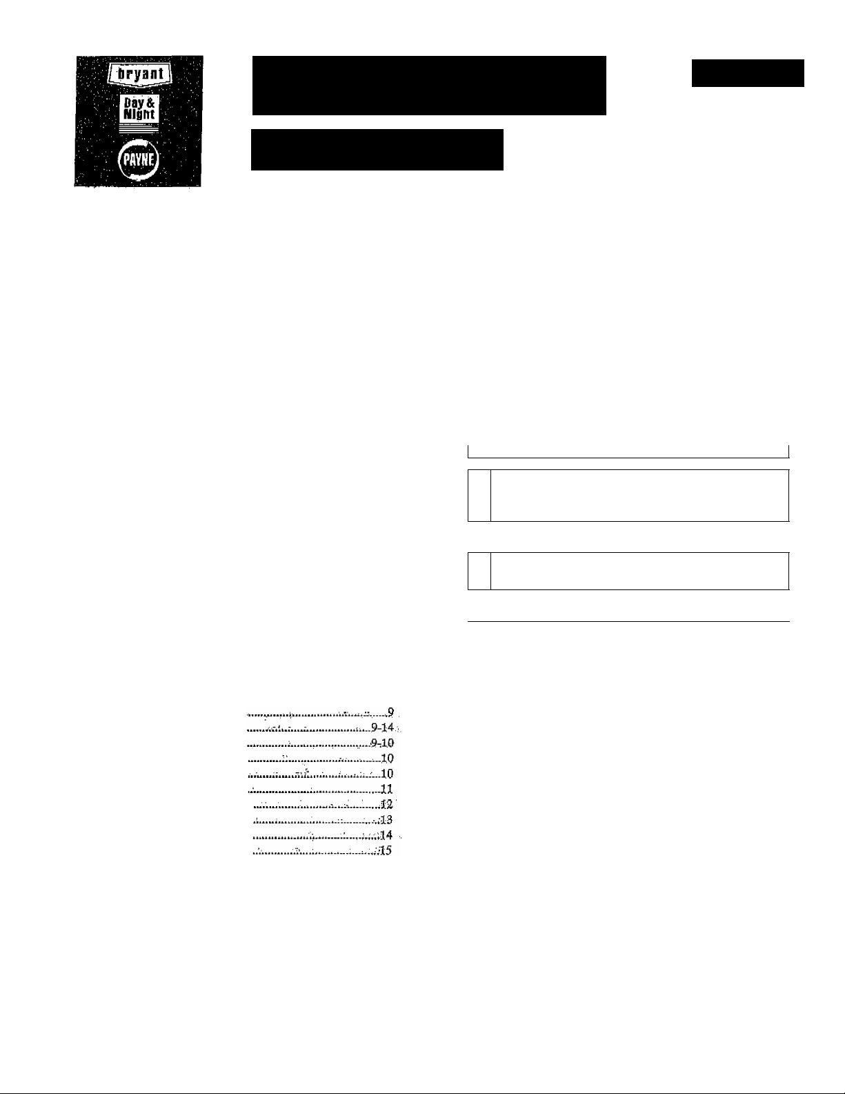
Fig. 1"™Component Lopation..
3. Remove rosette from around fluc;oonncctof, ' . „
4. Remove front panel and flue panel from Unit,
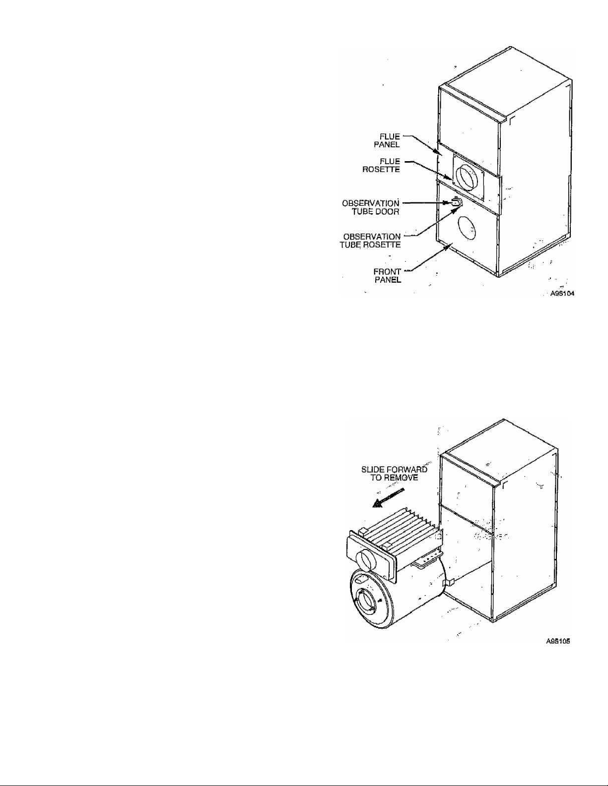
IMPORTANT: The heat exchanger is only secured in place by
heat exchanger ..support legs ,hopked into, brackets on blower
partition at this time. Care should be taken to adequately support
heat exchanger and prevent if from falling. Be careful not to
damage limit control.
5. Supporting heat exchanger so that it does not fail, remove
heat exchanger from cabinet by pulling it straight forward,
(See Fig. 2.)
0 0 5 / 0 1 6
I. KEEPING FILTERS CLEAN
As a homcownerj this is your mbit important respo'jiisibility. A
dirty .filter. LteduCes ¿f^ficiency. df 'your ,System, causes erratic
perforipance of controls, and could result,in damage to^motor or
heating equipment. . г.
1- Inspect filters at regular intervals depending upon dirt
conditions.'pof ■'hew homes, ehcplci'fiUcrs every weeliTor 4
consecutive weeks, iln all cases, inspect filters at least every
3 to 4 weeks when sysfem is inPoiistant operation. Replace
or clean filter at least at beginning of each season (heatirig
and cooling) and thereafter as ■needed.
2. If a permanent filter is used, it^can be cleaned witl); cold
water,and soap. ;; . , ,
Be Sure that filter is thoroughly dry before installing bacic' into
furnace. - ‘
reversing INSTRUCTIONS FOR REAR FLUE^OPTION ,
NOTE: These steps are only for installations where it is nfecessaiy
to have flue ccumection on Opposite side of furnace from biimef
and controls, Jf rear flue is not required, skip to Assembly
Instructions section.
Unit should be reversed prior to installing cabinet iri position. See
Fig, 1 for cdhiponent location, '' '
1. Remove observation tube door from front panel* taking care
not to let door spring ’’snap" hinge and pinch your fingers,
2, Remove flat rosette and gasket fram around observation
tube,-
Fig. 2—Removing Combustion Chamber and
Neat Exchanger
6. Remove cover plate/combugtion chamber assembly from
heat'exchanger drum by removing 12 parkerized screws
securing it to drum front. CAREFULLY slide combustion
chamber out of drum, taking care not to damage relatively
fragile chamber material- (See Fig, 3.)
7- Remove "blank" cover plate on rear of drum by removing
12 parkerized screws on dnim rear. Install this "blank" plate
on front (flue connector side) of drum. Ensure that gasket is
intact and all screws are secure.
-5^
Page 6
A Ï Ï G / 2 6 / 2 0 0 8 / T U E 1 0 : 0 2
UTC TECH PUB
) . 3 1 7 2 4 0 5 6 6 2
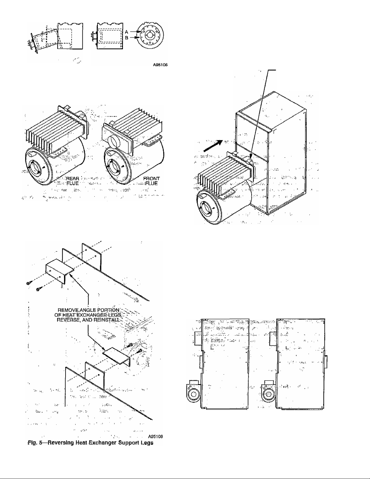
11. Turn heat exchanger so that flue connector is toward rear of
unit and reinstall in cabinet. The heat exchanger support
legs will now engage in hangers at rear of blower partition
instead of hangers at front. The fine connector should
, protrude through opening in flue panel on rear of unit with
burner mounting flange still at front of unit. (See Fig. 6.)
P ,
Fig, 3—Removing Combustion Chamber
8. Install cover platc/combustion chamber assembly (removed
in item 6) into rear opening of drum, taking care not to
dnm&ge chamber, cin^unng gasket is Jn-place, and verifying
that screws are ialEseeurely tightened. (See Fig. 4.)
- 'Ags'fci?
Fig. "4—Front/R^r Flue Üflehtatibhs
9. Remove 2 screws that attach angle portion of heat eX“
changer legs to straight portion, rotate angle portion so that
they point thti opposite direction, and reattach to straight
.portion,>using.priginal screws. (See Fig. 5.)
HOOK SUPPORT u
LEGS UNDER,
CLIPS ON REAR
OF BLOWER PANEL
INSTALL BY
SLIDING BACK
Fig. 6™ReinstalMng Combustion Chamber and
' ■ i' Héât Exchanger "
A951Û9
12. Reinstall frOni pà^erîfemdv^^ 4) and install rear
ccoterT?ancl,(rcmQyc.d îh.ithiii..liQ whdrfeZfliic panel origi
nally was. BE CAREFUL NOT TO DAMAGE LIMIT
CONTROL.
13. Replacp. rosette op ^i^.C!C|nncctpr (now at rear of furnace),
observaMon tube^ rosette M door. ■
14. ;;Froceed with'lnstàllîng futhaçeicabinetTand. mounting oil
bumer.:and controls. .■
FRONT FLUE
(AS SHIPPED)
. REAR FLUE
(AFTER REVERSAL)
10. RentOve rear center panel from cabinet and replace it with
flue panel removed in item 4.
A95110
Fig, 7—Component Location Before and After
Flue l^eversal
^6-
Page 7

A U G / 2 6 / 2 0 0 8 / T U E 1 0 : 0 3
It is easier to install furnace if cabinet assembly (shipped in carton
■ 1 of 2) is placed into positionj ductwork connected, and THEN
control box/burn,er assembly (shipped in carton 2 of 2) is mounted
to cabinet. Electrical^ thermostat^ and oil line connections can then
be made to completed unit.
To attach control box/burner assembly to cabinet:
1. Carefully unpack carton 2 containing prewired control
box/burncr assemb.ly .and hardware bag.
2. Remove 3 burner mounting nuts securing shipping plate on
front of furnace cabinet at burner mounting flange. Remove
and discard shipping plate. When furnace is in installed
position^ burner mounting studs should be in the 12, 3, and
9 o’clock positions, leaving bottom hole empty.
a. If furnace is being installed in downflow position, studs
are in correct .position wjie^ ,shipped from factory, ‘
. b. ff furnaceJs beingJnstallcd in horizontal position, it is
necessary to remove stud that ris mow in .6 .o^dlock
posirioti and reposition it so thaFstuds are in l2, 3', and
9 o’clock positions. It may be necessary to use Z of the
burner mpunting'iiuts as ''jsrrr"> puts pn. stud in order to
provide a means of using a‘wrench to remove,a tight
stud. 1.'
3. If furnace is installed in horizontal left airflow positíoii, it is
necessary to relocate burner wiring conduit from'ii^t side
of burner to left side as follows: (See Eig. S.) ^ > i-.-.,
a. Release clip(s) securing ignition control ^on top of burner
and swing control open to gain access to wiring com
partment inside burner.
b. Disconnect wire nuts on .black, white, and orange, wires
inside burner.
c. Remove conduit nut securing conduit to right side of
burner and detach conduit and .wires from .burner/housing. .
d. Reipovc hole plug from left side of burner housing and
install it in hole on right side (where :;Condujt was
removed). ... ^ ,
e. Feed conduifand ¡wires through-(eft^side hofe and secure
with conduifnufremoved imlteirij c'.^ ■/;
f. Reconnect blacki white, and orange wires inside burner
using'wire nuts removed in item 'b.
Close anB secure ignition control.
f'f-V., ' 'i.H| 1'.'
4. Carefully'install burner onto burner mounting,studs, ¡ensur
ing that mounting flange ¡gasket is jpositioned between
. flange on .burner .and fronf pf furnace.. Secure, .burner ¡in
position with 3 burner mounting.y^ashers,and.iiuts removed
in item 2. .if;.
IMPORTANT: The burner must álwayS’bfe^jnstdlled in upright
position with ignition control on top, (Sec Fig. 9i)^
5'- Attacft bontfol bok to bloyi'CT'abéMsS
sTieet 'métál'''Screws ‘froin ''hárdw'ain:'''t7'¿g''in' carton '2. The
vyirés exteh'diug .frOm'biower access párífcT.muk be routed
through large ho)c)n back of control bóxj taklng ¿aré not to
gcrapt o'rjpiiich insulation on wires.'The wires''¿hotild be
connected to1:he 2-pin harness conhéctor ánd aflfíropriate
terminals on fan control board. (See Fig. 10 arid Í6-)
o
6. Attach the 2 limit switch , wires to terminals of limit switch
located on lower portion of front panel. After attaching
wires, secure limit cover to front panel using 2 No. B sheet
.metal screws from hardware bag in carton 2, (See Fig. 11.)
UTC TECH PUB
ASSEMBLY INSTRUCTIONS
......
F A X N o , 3 1 7 2 4 0 5 6 6 2
iiimiiiiiiiinm
llllllllllllllllllj
CONDUIT LOCATION
FOR HORIZONTAL-RIGHT
{AFTER RELOCATING)
Fig. 8—Burner Wiring Conduit Location for
Horizontal Applications
(Downflow Orientation Shown)
0 0 7 / 0 1 6
CONDUIT LOCATION
FOR DOWNFLOW
AND HORIZONTAL-L^FT
(AS SHIPPED)
ASSÍ11
-7-
Page 8

A U G / 2 6 / 2 0 0 8 / T U E 1 0 : 0 3
UTC TECH PUB
F A X N o . 3 1 7 2 4 0 5 6 6 2
P .
(5>
CONSTANT BLOWER
ROCKER SWITCH
2 - FOR STHE..155.MODEL OR
3-FOR THE 125 MODEL
R = RED BK = BLACK \N = WHITE
Fig. lo-T-Blowor Control Board
АЙЙИЙ
^s~
WARNING: Do not u$c this furnace as a construction
heater. Use of this furnace as a construction heater
exposes furnace to abnormal conditions* contaminated
combustion air* and lack of air filters. Failure to follow
A
this warning can lead to premature furnace failure and/or
vent failure which could result in a fire hazard and/or
bodily harm, ■
WARNING: Installation of this furnace in an area where
it, will .receive .contaminated combustiq^, air .¡nust be
avoidetl. Such contamination would include the follow
ing: ammonia, chlorine, hydrogen sulfide, halQgenated
hydrocarbons, carbon tetrachloride* cleaning solvents,
A
hydrochloric acid, water softening chemicals, and similar
chemicals, failure to follow this warning will lead to
premature rusting of heat exchanger and possible furnace
failure: .iand/or. Vent failure- which could result in fire
hazard and/or bodily .rharm. :
^ OPERATIÜNAL^GHECK^
DO -NOT''START^BURMER :UNLESS BLOWER ACCESS
PANEL IS SECURED IN PLACE.
Installatigm of-furnace is novv .f;oinplete and operational ^checkout
may b&;:parforffled., ,_V, 2 ■■
I. START^UP : V,
1. Check wiring against wiring'diagram shown in Fig. 16.
2. -Open valve on oil siipply line. '
3. Reset primary control.
4. Set thermostat above room temperature.
5. Set main ebctrical switch to ON position. Вигам should
start. ■ '
DO NOT TAMPERS WITH UNIT OR CONTROLS - CALL
YOUR SERVICE. TECHNICIAN.
II. RECOMMENDED INSTALLATION PRACTICES AND
COMBUSTION CHECK -
In order to obtain optimum performance from oil burner, the
following^setupiprocedurés must be followed: ' i- ,
1. A test kit (Bachafach No, 5022; kif^f equivalent to’measure
smoke, stack dfaft, over:^fire draft, COj, and:stacfc témjperatures MUST be used in order/to’.ohtaiti pfopur mr band
setting. Although all. of the^aboyc measurements a^s re
quired for optimum setup and' efficiency data, the most
important:readings that.mustbe taken are smoke numbers,
■■; ■ ,ov.er-Ere (draft,- :and stackrdra^t:.
2. The'proper-smolid number' has,.b?en established by etigi-
- ■' ■ n'eeririg' ÍeSts tii b¿ -between 0 arid 'I'.' This degree of sm oke
emissions is commonly referred to as a "Trace" of smoke. It
is recommended to use a^Bacharnch^true spot smoke test set
or equivalents - - ' ;í^■ tci'/v or-
3. In order to ensure proper dr^t,thqugh..furnace, g b^roroctric
draft regulator .(supplied, with furn4po|), must .hjs in^talícd as
close to outlet of furWee a's "poss^bl^^^^ to
function .properly, barometric ОаГОрёт'щцд!. be'mounted
with^hinge pins horizontal an^ faceipf datiíp^ veríical, (See
iristníctions included with .^эщреН) 'Lhe dr aft.,Regulator
should be adjusted after ifuniace has been firing at least
5 minutes, and stack draft should be measured and set
between-'-0:025 ¡and -ОЮЗЗ'in. wc. The draft should be
checked with, a Bacharach MZF draft gage or equivalent.
4. The dver-firf: drilft* Which is taken th/o'ugh hole provided in
observation door, is a measurement necessary to determine
if there is a blockage between oil burner and Sue outlet.
О
Page 9
A U G / 2 6 / 2 0 0 8 / T U E 1 0 : 0 3
UTC TECH PUB
F A X N o . 3 1 7 2 4 0 5 6 6 2
There showJd b? e prtsspte irop of between 0.005 and 0,020
in. wc through furnace. This would set the range of the
over-fire draft between -0.01 and ~0.03 in. wc. A reading
above -0.01 in. wc (for example +0.1 in. wc) would indicate
that furnace is in an extremely high-pressure condition in
primary section- This condition may be caused by excessive
combustion air due to air baud being too wide open or.a:]ack
of flue draft (chimney effect) or some other blockage, such
as soot, in secondary section of heat exchanger.
5. The COj and stack temperature instruments ciiable you to
obtain data required to determine thermal efficiency of
furnace.
6. An oil filter should be installed as close to burner as
possible with ALL oil burners and is essential On lower
firing rate burners. We recommend the Use of a low
pressure drop oil filter such as the General Filter, lup, model
#lA‘í25A Of equivalent. It is .critical that oil capacity be
equivalent or greater than fuel pump gear capacity. For a
2-pipc system, this is 25 gph.
7. The oil pressure regulator is factory set to give uo^ile oil
pressures of 100 psig. The firing rate noted on nameplate
may be obtained with "standard" nozzles by adjusting pump
pressure as noted in Table 3 or on label iop fumacç,
TABLE 3—BURNER, NOZZLE, ANÒ PUMP PRESSURE
CHART
UNIT
SIZE
036070
036090
040125
046155
FIRING
RATE
GAUHR (US)
0.50
0,65
0.9Q
1.12
PUMP
PRESSURE
(PSIG)
100
100
100
104
&ECKETT OIL BURNER
Model
AFG
^ AFG
AFG
AFG
Nozzle
0,50 gph
80“ Solid
0-65 gph
70“ Hollow
0.90 gph
70“ HOMw-
1.10 gph
70° Hollow
On a new installation, air entrapped in oil line leading from
tank to nOizIe must be thoroughly purged in order to
prevent excessive after drip. The oil pump is provided with
a Special fittihg enabling'^bu to purge any air between tank
and oil pump. The proper .procedure for performiuS this
operation is as follows;
a. Place a piq^pc of dear plasticT/4-in. diameter tubing over
purge fitting on oil pump. . '
b. Start oil burner, then open purge fitting and aillow burner
to run until purge tube is completely free of air bubbles.
’ c. Tighten purge fitting .which will allow oil'to fun to
nosizle and fire burner.
d. If purging takes longer than „3,0 seo and no flame has
been, established, burner stops- i^ush reset button on top
of primary contro] to restart burneri
e. For detailed information On Operation of primary control,
refer to instructions included with furnace,
S. After all setup procedures mentioned above have been
completed, burner should be allowed to operate. Use an
■ inspection mirror to observe flame pattern. Any irtegularities such as burning to 1 side or pulsating flame patterns
should be corrected by changing nozzle.
III. FAN ADJUSTMENT CHECK
This furnace is equipped with ft 3-5pccd direct drive motor to
deliver a temperature rise within range specified on rating plate,
between return and supply plenums, at external duct static pressure
noted on rating plate.
Adjust fan speed so that temperature rise is within rise range
specified on rating: ¿plate. Consult wiring diagram for speed
changes on direct-drive motor. - „
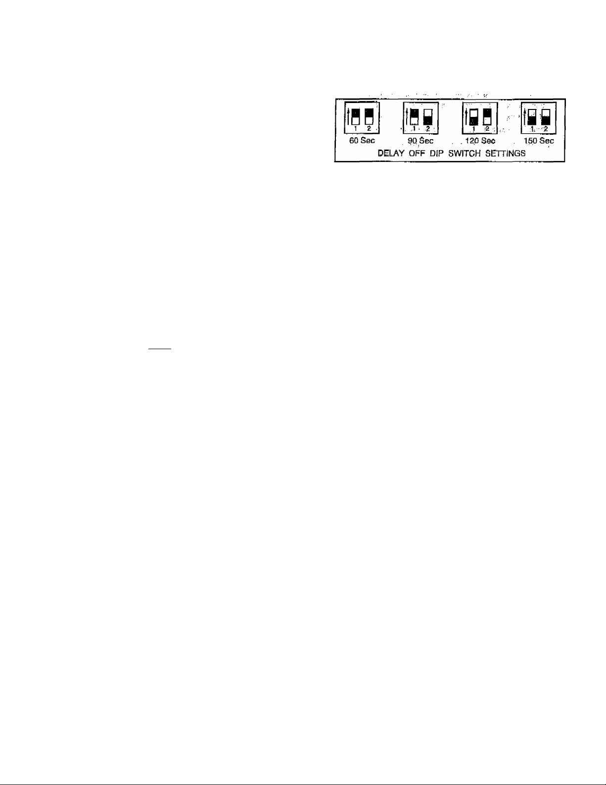
To adjust fan off time, get DIP switches on control board to obtain
desired timingV(See Fig, 12,)
■ Vf.
AS5116
Fig. 12^Fan Off Time DIP Switch Settings
IV.
LIMIT CONTROL CHECK
After furnace has been in operation for at least 15 minutes, restrict
rctum-air supply by blocking filters or closing return registers and
allow furnace to shut down on high limit, Th<: burner should shut
off, and main blower should continue to run.
Remove restriction, and burner should come back On iij a few
minutes, V'
V. FOR YEAR ROUND-air CONDmONING
This furnace is designed for use in crinjunction-with cooling
equipment to provide year rgund air conditioning. The.blower has
been sized for both heating and cooling, however, fan motor speed
may heed to be changed to obtain ncccsshry codling airflow'.
VI. HEATING
The blower speed is factory set to deliver required-airflow at
normal duct static pressure.
VII. COOLING
The blower spqcd may be adjusted in the field to ¡deliver required
airflow,for cooling application^CScc Eig, 16.)
VIII. CONSTANT BLOWER SWITCH
Thib furnace is equipped with a constant low-speed blower option.
Whenever room thermostat is not calling for heating or'cooling,
blower runs on low speed in order ;to provide air. circulation. If
constant blower option is not desired, the rocker switch-on side of
control-box .may-bc-uscdfo-turn-off-constant-speed.- .
This furnace should .never be operated, vvithout air ,filt6r(s)..Filters
' MAiNtENArjce: '7 T7 -
should be cleaned at least twice a year.
To avoid personal injury, make sure electrical supply power is off
before servicirig. ^ .
ALWAYS KEEP MAIN ' OIL VALVIE/TURhnED./PFF IF
BURNER IS SHUT- DOWN FOR AN EXTENi?Et? PERIOD OF
_
, ^ L>v * _. *.■ . I ' T ,
TIME,
WARNING; Before performing any service functions,
unless Operations specifically require power to be on,
A
make sure all utilities are turned off upstream oL appli
ance. Failure to-comply with this warning wili cause a fire
hazard and/or bodily harm. <.
I. OIL BURNER
Per jodio oiling of blower motor may be necessary. Check for
instructions on inside of blower access panel.
To maintain proper performance, ’ oil burner nozzle must be
replaced once a year. Contact your dealer service technician if you
arc unsure of this procedure.
The procedure for nozzle installation and/or replacement is out
lined in oil burner instruction manual which came wi№ furnace.
For ease of maintenance, the oiling procodure for burner motor, as
Outlined in burner manual, should be performed at this time.
-9-
Page 10

A U G / 2 6 / 2 0 0 8 / T U E 1 0 : 0 4
UTC TECH PUB
F A X N o , 3 1 7 2 4 0 5 6 6 2
After rcpiacxment of nozzle, burner should be adjusted in accor
dance with Combustion Chccjt.. section of the mstnicUon,
II. HEAT EXCHANGER AND FLUE PIPE
Ordinarily, it is not necessary to clean heat e^pçl^anger or flue pipe
every year but it is necessary tp have your oil burner service
technician" check uhit bcfôrc caçh ‘heating season to determine
whether ^leaning or replacement of parts/is repujreti.
If cleaning is necessaiy, the following^Steps should be performed:
; i."Turn off all utilities upstream of fiimace.
. 2..Disconnect flue pipe,.
3, Remove collar on flue connection.
4. Rempye:flue'.panél,'.¡"i":
5. Remove flue collector b6x¥fûih-sé'côhdafÿ:ihea"ïièxchangér
., , tube flange. This ^exposes inside surfaces.pfisecqn^ary tpbes
of .heatÆXchàngerVi^ rA,A'i A
6, clean secondary iubtis and flüc pipé with a stiff^briish ^nd
vacuum cleaner!'■■■■'v. - ■ n^r i,;;:
'7. if only "secondary "tubes' nCd^cicà'heH^'no;'further
disassembly is required. Proceed to item IS for reassembly.
If primâr^ÿ "heat ^exchariger' ^seCtion ^'iS"'àlSo -to'^'be'''cleaned
■pr.ocecd..;tpinçxt.item:;,.
g : 'Disccinnect'‘Tim ft cbntrdl ■ wireè. ' ' ^ ; 1.1.
'l. i.y''/;....., . ! '.iir rt}'' . ..--i.,.
9. Disconnçqt oil lme..and renioye oilJiurner fr.om fernaeç,
10- Remove observation door. .'îÆj ' ,,
; 11,'Remoye„collar'iOn;0b5crv,^tionfubc. ■ .ij . . '
12. Remove front panel. Care must-be takeji('-not tb'bbnd Or
damage 'limit control. ' 'i
■ 13. Looscri''to-'hand tightness "the'3 nütsdabeled' f'A" in Fig;'i3,
Remove screws labeled ""B" in Fig, 3, Slide combustion
chamber forward put.of heat exchangeri,Be*careful not .to
bqmp, .combustion chamber as it become^ brittle^ ^^Çer
A ' having been fired.
■ 14. Use.-a.stiff brush and vacuum iC)eaner/tO 'dean-,inside^'bf
primary^drum:,. -.r,. ..^ ■■ ■. :ivt.v. ■■■i.-. ' ..
CAUTION: Never-use incendiary type cleaners (smoke
A
sticks) for cleaniiigT‘ A
i .
1^. Befbre reáSsemtíiyríisaTexcEánger^
ber sJjOuIi^.be m^pCcted to deterinine ,if;iqp^
required .;!“^er ^lea'mng,,piace^'dp'n;l(bus
'■ ' ^ into'primary drum'and secure witli''''B"'SCrews';'Bnsuriprth^^
cover plate gasket is in place.before tightening screws:' Cái¿
'"■■ ■ müít be taken"'nüt'td'’aaroagéi:dfflbii';^fjdh":c’j^iiji[íbí^^
i.f: ■■ ,.r, yi .-I..' ■
16. Tighten'"A"-nuts to!30 lb-ip. of torque,(firm^,butj]ipt Overly
.. flghO-.i,.--. •••■> ■ .■ :n;.' (;■ ■mi ciiif ■ ■
17. Replace front panel, bbservatiOri^tube collar^ óbseryation
door, Um.U .wiring, and oilbiirner. ■ ■ - .
IS. Replace collector box on secondary tube flange, ensuring
proper placement of gasket. IF GASKÍETt IS^DAMACED
IN ANY WAY, IT SHOULD BE REPLACE,D! Tighten
screws'fü'30-lb-in. Of torque.’'
19. Replace flue panel and flue COUaL^ ■
20. Reconnect flue pipe, and :oil,pipéis) if removed;; Í ■
21. Readjust burner for proper operátíbií. Check limit operation
as outlined in this manual,
lU. pLÓWEíi RfeMpVAL
To remove (blower from furnace;-
■■ . ■ -'j. ■ f.;-' 'I' .■ '.
..............
NOTE: All directions are given as though fiimacc were installed
in downflow position. For either horizontal position, "left" and
"right" become "up" and "down" depending on position in which
furnace is installed. /
1, Turn off all utilities upstream of furnace.
2, Remove control box cover and disconnect black, red, blue,
and White blower wires from blower control board and
constant blower rocker switch. (See. -Fig. 10.) Disconnect
2-pin harness connector for auxiliary limit wires.
3. Remove screws securing blower access panel and rotate
panel (with control box attached) down and out of way of
blower compartment. B,e careful pot to scrape or pinch
blower anid auxiliary limit wires ps they pull through wiring
hole in panel. 7j ,,
4. Remove blower retaining screw located at front of left
blower leg. (See Fig. 13.) '■
Aa$iie
f
Fig. 13-^Blower Rfitalnlng Screw
5- Slide Blower frirward bn fSii^'^&nd but, Of unit: Cafe must be
taken not to.scrape or pinch motof br 'liihit wires.
CAUTION: Be sure blower ?Js : adequately supported
when sliding opt pf mq,unring rails,iespccially ioihorizon-
A
tal posiflon,..jn ofdcr tp .pre^^^ dropping blower and
injuring yourself or damaging blower!
t::-
■6, Reverse items 1 thrblighiS to r^ihStdR blOwCr..Refer to Fig.
10 and. wiring diagram ^(Figi ‘16) -of this instruction, or
diagram located on inside- of blower ¡access panel to
properly rewir^.unit-
-10-
Page 11

AUG/26/2008/TUE 10; 04
UNIT
SKE
036070
036090
04S125
046155
NOTES: 1. Airflow VBluea in cubic ft par minute toundcd to nearest S CFM.
s. Data taken without filters in place.
BLOWER
SPEED
High
Medium
Low
High
Medium
Low
High
Medium
Low
High
i*
Medium
Low
UTC TECH PUB
TABLE 4—AIBELOW DATA (CFM)
0.1
ises
1250
905
158S 1530
'1250
905
1065 1795
1725
1505
i960
1790
1460
0.2 0,3
1530
1220
670
1220
870
1676
1475
1900
1740
1430
1470
1185
S45
1470
1185
845
1720
1610
1430
1840
1685
1380
FAI No. 317 240 5662
EXTERNAL STATIC PRESSURE IN. WC
0,4
1405 (1350
1130
795
1405 1350
1130
795
1650
1545
1375
1776 1700
1605
1340
0.5
1080
765 ^ 730
1080
765 .
1610
149P
1325
1545 1475 1280
O.B
42S0
1050
1280
1050 1000
730
1520
'1420
1270
1625 1550
1220
0.7' 0,8
1215
1000
690
1215 .
690
1455
1350 ^
1200
1415 ^
1145
P.
0.9
1140
‘ 925 /855
650 600
1140
925 855
650
1380
1270 1200
1145 1065
1465
1330 1250
1080
1075
1075
600
1295
1380 1285
1015
1.0
985
785
565
985
705
565
1215
1110
970
1160
925
^ 1 1
—
Page 12

A U G / 2 6 / 2 0 0 8 / T U E 1 0 : 0 4
RETURN AIR
OPENING
UTC TECH PUB
ELECTRICAL
ni
N o , 3 1 7 2 4 0 5 6 6 2
7 0 1 2 .
r
1
UNIT
SIZE
□3S070
036090
048125
048155
UNIT DIMENSIONS
Depth
20^/4
20-'3/4
25'3/4
25^3/4
Width Height
A
20
2b
22
22
‘^4"
A9437S
DIMENSIONS (IN.)
DUCT SUPPLY OPENING
B
C
46'
■■ -J-g'"'' -■■■■
46
48
D
2Ó
Fig. —Dimensional Drawing
E
, 17
22
22
DUCT RETURN OPENING
D
18
16
20
20
E
17
17
22
22
FLUE
LOCATION
F
10
10
11
n
FLUE
DIAMETER
G
6
6
e
s
Page 13

AUG/26/2008/TUE 10:04 AM
UTC TECH PUB
BAROMETRIC DAMPER LOCATIONS
FIG. D
1,31 7 240 5662
P, 013/016
GOOD LOCATIONS
-I- •
BAD LOCATIONS
Fig. 15—Barometric Damper Locations
POOR
A95117
Page 14

>=c=l
!:r:i
t-O
t-O
CZJ
oo
>=-
—3
O
—3
O
-C
od
c
Fig. 16—Wiring Diagram
'I
Asstia
-3171
>=-
>=i
on
t-o
Page 15

A U G / 2 6 / 2 0 0 8 / T U E 1 0 : 0 5
UTC TECH PUB
F A X N o . 3 1 7 2 4 0 5 6 6 2
0 1 5 / 0 1 6
USER’S INFORMATION
I. HERE’S HOW YOUR HEATING SYSTEM WORKS
The furnace operates autpipaMcaJly, It is controlled by a thermostat
which you set at temperature most comfortable to you. When the
inside temperature drops below this setting, your thermostat will
turn on heating system.
When thermostat call for heat, power from transfotmer energizes
fan control board* The fan control energizes ignition control. The
ignition control lights burner automatically.
The electronic fan control automatically turns On blower after 30
sec. Fan on control Js not adjustable. The air moved over heat
exchanger by the blower is warmed and passes through ducts to
room registers.
When thermostat is satisfied, the circuit is de-energized and
primary control shuts off burner. The blower continues to run until
selectable fan off time period has expired.
The heat sensing switch performs as furnace high-temperature
limit switch. If furnace overheats for any reason, the limit sviijtch
opens, breajiing circuit to burner. The blower motor is energized,
and as unit cools, the limit switch closes. This will relight burner,
but unless overheating condition is corrected, furnace will cycle on
limit.
This unit is equipped with an interrupted ignition electronic
control. If main burner does not ignite within 15 sec from cal) for
heat, the control goes into lockout. The red button On top of control
must be depressed for 3 sec in order to reset control. The control
CANNOT be reset from room thermostat.
II. PREPARING YOUR FURNACE FOR OPERATION
Before attempting to put your furnace into operation for the
heating season, you should perform the following procedures:
WARNING; If you do not follow these instructions
A
exactly, a fire or explosion may result causing property
damage, personal injury, or loss of life.
1, Open all warm-air registers and make sure all retum-air
grilles arc unobstructed.
2. If a humidifier is installed with your system, open water
supply valve.
3. Set thennostat to lowest setting.
4. Turn On electric power to furnace.
5. Open oil supply valve.
6. Check all connections to ensure there are no leaks.
Ill, LIGHTING YOUR FURNACE
CAUTION; This furnace is equipped with an interrupted
type electronic ignition system. DO NOT ATTEMPT TO
A
nOHT WITH A MATCH.
HIGH VOLTAGE AT IGNITOR.
1. This appliance is equipped with an ignition device which
automatically lights burner. Do NOT try to light burner by
hand.
2. After preparing furnace for heating operation (see previous
section) and checking for oil, proceed as follows,
3. For heating/cooling system, set thermostat to HEAT and fan
to AUTO. Set thermostat to desired room temperature and
turn on electrical power to furnace.
4. The burner should light and system should be controlled by
thermostat.
IV. TURNING OFF YOUR FURNACE
Follow these simple procedures to put your furnace into "retire
ment" for the summer.
1. Set thermostat to lowest setting.
2. Turn off all electrical power to appliance.
3. Turn Off Oil supply.
4. If applicable, turn off water supply to humidifier.
5. If furnace blower will be necessary for cooling system,
remember to turn electrical power back on when needed for
air conditioning.
NAME:
ADDRESS;
TELEPHONE:
FOR SERVICE CALL
Page 16

A U G / 2 6 / 2 0 0 8 / T U E 1 0 : 0 5
UTC TECH PUB
■A' i
3 1 7 2 4 0 5 6 6 2
n
■■ ¿' '
, Tri- ì
ri*-'
e 1993 BOP Cd. ■ P.O. Bùie 70 ■ IndlanapoJIS, IN 45206 Printed in U.3.A, — 16 —
CJ
364fl701 CùtalDg No. BDP‘9996-400
 Loading...