

Page 1

TC-32B Title
TC-32B
NC PROGRAMMING
MANUAL
Please read this manual carefully before starting operation.
2003/4/21 1 eTCOMNCPRT1.doc
Page 2

TC-32B Title
This manual describes the NC-Programming of the TC-32B.
The tapping centre is able to perform drilling, tapping, and facing.
We shall not bear any responsibility for accidents caused by user's special handling or handling
deviating from the generally recognized safe operation.
1
The relation between the manuals is as follows.
- OPERATION MANUAL
This manual describes the operations of the machine.
- INSTALLATION MANUAL
This manual describes the installation of the machine.
- PROGRAMMING MANUAL
This manual describes the programming of the machine.
Keep this manual for future reference.
Please include this manual when reselling this product.
When this manual or labels are lost or damaged, please replace them (charged) from your nearest
agency.
This manual is printed by using paper obtained from farmed trees.
2003/3/20 2 eTCOMNCPRT1.doc
Page 3

TC-32B Title
INTRODUCTION
Congratulations on your purchase of the Brother CNC
tapping center. Correct usage of the machine is of most importance to assure the
expected machine capabilities and functions as well as operator's safety. Read this
Manual thoroughly before starting operation.
* All rights reserved: No part of this manual may be reproduced, stored in a retrieval system,
or transmitted in any form without prior permission of the manufacturer.
* The contents of this Manual are subject to change without notice.
* This manual are complied with utmost care. If you encounter any question or doubt,
please contact your local dealer.
© Copyrigt 2004 BROTHER INDUSTRIES,LTD. Machinery & Solution Company.
Machine Tools Field. ALL RIGHTS RESERVED.
2003/4/21 3 eTCOMNCPRT1.doc
Page 4
1
y
TC-32B Title
HOW TO USE THE MANUAL
This Instruction Manual consists of the following elements:
(1) General description Is an outline of the description given in the section.
(2) Alarm Is a alert given against a danger which may cause serious
damage or death to human being or may damage the machine.
The hazards are explained in this order:
degree of danger,
subject of danger,
expected damage,
preventive measure,
(3) Operation procedure Is a procedure of activating a function.
(4) Screen Is given to describe important points of a procedure given.
NOTE: This screen is only a representation of the information
displayed on the actual screen and therefore differs
somewhat from the actual screen
layout and screen fonts.
(5) Illustration Is a sketch, figure, view, etc. indicating dimensions, position or zone, given
in the points where it is necessary to provide complementary information to the text
description.
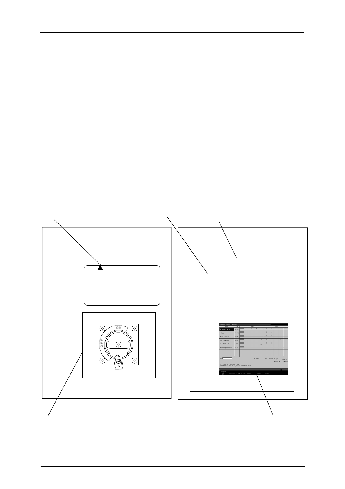
(2) Alarm
(3) Operation procedure
WARNING
Dropping a heavy object onto
your foot may fracture your foot
bones.
When lifting heavy objects,
wear safet
shoes.
(1) General description
1.3.1Before starting operation
Before starting operation careful to read bellow.
(1)Tu rn off the main pow er break er hand le on
the contro l box doo r. Never touch t he primar y side
power source or the terminal of the main power
breaker, as these have high voltage applied.
(2)Put up a signboard w hich says ' Under Mainte nance
(3)Never allow people to approach the mach ine,
particularly moving areas.
(4)Do not place any unnecessary object around the
machine.
(5)Wear a helmet and safety shoes.
1 - 2
(5) Illustration
2003/3/20 4 eTCOMNCPRT1.doc
1 - 3
(4) Screen
Page 5

TC-32B Contents
Chapter 1 Program Composition-------------------------------- 1-1
1.1 Types and composition of program ------------------------------------1-2
1.2 Composition of block -------------------------------------------------------1-2
1.3 Composition of word --------------------------------------------------------1-3
1.4 Numerical values ----------------------------------------------------------1-3
1.5 Sequence number ---------------------------------------------------------------1-4
1.6 Optional block skip -------------------------------------------------------------1-4
1.7 Control out/in function---------------------------------------------------------1-4
Chapter 2 Coordinate Command -------------------------------- 2-1
2.1 Coordinate system and coordinate value -------------------------------2-2
2.2 Machine zero point and machine coordinate system ---------------2-3
2.3 Working coordinate system--------------------------------------------------2-3
Chapter 3 Preparation Function --------------------------------- 3-1
3.1 Outline of G code ----------------------------------------------------------------3-2
3.2 Positioning (G00) ------------------------------------------------------------3-9
3.3 Linear interpolation (G01) ----------------------------------------------------3-10
3.3.1 Chamfering to desired angle and cornering C ----------------------------------------------3-11
3.4 Circular/helical interpolation (G02, G03) --------------------------------3-14
3.4.1 Circular interpolation --------------------------------------------------------------------------- 3-14
3.4.1.1 Circular interpolation ---------------------------------------------------------------------- 3-14
3.4.1.2 XZ Circular interpolation ----------------------------------------------------------------- 3-15
3.4.1.3 YZ Circular interpolation ----------------------------------------------------------------- 3-16
3.4.2 Helical interpolation----------------------------------------------------------------------------- 3-20
3.4.3 Spiral interpolation (G02, G03) --------------------------------------------------------------- 3-21
3.4.4 Conical interpolation (G02, G03) -------------------------------------------------------------3-23
3.4.5 Cutter compensation procedure for spiral interpolation and conical interpolation
(G02, G03) ---------------------------------------------------------------------------------------- 3-26
3.5 Circle Cutting (G12, G13) -----------------------------------------------------3-27
3.6 Plane Selection (G17, G18, G19) -------------------------------------------3-28
3.7 Dwell (G04)-------------------------------------------------------------------------3-29
3.8 Exact stop check (G09, G61, G64) -----------------------------------------3-29
3.9 Programmable data input (G10) --------------------------------------------3-31
3.10 Soft limit ----------------------------------------------------------------------------3-34
3.10.1 Stroke --------------------------------------------------------------------------------------------3-34
3.10.2 Stroke limit --------------------------------------------------------------------------------------3-34
3.10.3 Programmable stroke limit (G22) ----------------------------------------------------------- 3-35
3.11 Return to the reference point (G28) ---------------------------------------3-36
3.12 Return from the reference point(G29) ------------------------------------3-37
3.13 Return to the 2nd/3rd/4th reference point (G30)----------------------3-37
3.14 Selection of machine coordinate system (G53)-----------------------3-37
3.15 Selection of working coordinate system (G54~G59)----------------3-38
3.16 Additional working coordinate system selection (G54.1) ---------3-38
3.17 Scaling (G50, G51) --------------------------------------------------------------3-39
3.18 Programmable Mirror Image (G50.1, G51.1)----------------------------3-43
3.19 Rotational transformation function (G68,G69) ------------------------3-46
3.20 Coordinate rotation using measured results(G168)-----------------3-48
3.21 Absolute command and incremental command (G90, G91)------3-48
3.22 Change of workpiece coordinate system(G92) -----------------------3-50
3.23 Skip function (G31,G131,G132)---------------------------------------------3-52
3.24 Continuous skip function (G31) --------------------------------------------3-53
3.25 Change of tap twisting direction(G133,G134) -------------------------3-53
3.26 High speed peck drilling cycle (G173)) ----------------------------------3-54
2004/01/19 1 eTCOMNCPRC.doc
Page 6

TC-32B Contents
3.27 Peck drilling cycle (G183) ----------------------------------------------------3-55
3.28 Local coordinate system function (G52) --------------------------------3-56
3.29 Single direction positioning function(G60)-----------------------------3-57
3.30 G code priority--------------------------------------------------------------------3-58
Chapter 4 Preparation Function (tool offset function) ---- 4-1
4.1 Tool Dia Offset(G40,G41,G42) -----------------------------------------------4-2
4.1.1 Tool dia offset function -------------------------------------------------------------------------4-2
4.1.1.1 Tool dia fine compensation ---------------------------------------------------------------4-2
4.1.2 Cancel Mode ------------------------------------------------------------------------------------- 4-3
4.1.3 Start -up ------------------------------------------------------------------------------------------- 4-4
4.1.3.1 Inside cutting -------------------------------------------------------------------------------4-4
4.1.3.2 Outside cutting (90° ≤ θ < 180°)--------------------------------------------------------- 4-5
4.1.3.3 Outside cutting (θ < 90°) ------------------------------------------------------------------ 4-6
4.1.4 Offset Mode -------------------------------------------------------------------------------------4-7
4.1.4.1 Inside cutting (180° ≤ θ) ------------------------------------------------------------------ 4-7
4.1.4.2 Outside cutting (90° ≤ θ < 180°)--------------------------------------------------------- 4-9
4.1.4.3 Outside cutting (θ < 90°) ------------------------------------------------------------------ 4-10
4.1.4.4 Exceptional case ----------------------------------------------------------------------------4-11
4.1.5 Offset Cancel ------------------------------------------------------------------------------------- 4-12
4.1.5.1 Inside cutting (180° ≤ θ) ------------------------------------------------------------------ 4-12
4.1.5.2 Outside cutting (90° ≤ θ < 180°)--------------------------------------------------------- 4-12
4.1.5.3 Outside cutting (θ < 90°) ------------------------------------------------------------------ 4-14
4.1.6 G40 single command ---------------------------------------------------------------------------- 4-15
4.1.7 Change of offset direction in offset mode --------------------------------------------------- 4-16
4.1.8 Change of offset direction in offset mode -------------------------------------------------- 4-17
4.1.8.1 When there is a cross point -------------------------------------------------------------- 4-17
4.1.8.2 When there is no cross point ------------------------------------------------------------- 4-18
4.1.8.3 When offset path becomes more than a circle -----------------------------------------4-19
4.1.9 G cord command for tool dia offset in offset mode ----------------------------------------4-20
4.1.10 Notes on tool dia offset ------------------------------------------------------------------------- 4-21
4.1.11 Override function related to tool dia offset -------------------------------------------------- 4-29
4.1.11.1 Automatic corner override -------------------------------------------------------------- 4-29
4.1.11.2 Override of the inside circular cutting------------------------------------------------- 4-30
4.2 Tool length offset (G43,G44,G49) -----------------------------------4-31
4.2.1 Tool length fine offset -------------------------------------------------------------------------- 4-31
Chapter 5 Preparation Function (canned cycle) ------------ 5-1
5.1 List of canned cycle function -----------------------------------------------5-2
5.2 Basic motions in canned cycle ---------------------------------------------5-3
5.3 General description of canned cycle ------------------------------------5-4
5.3.1 Command related to canned cycle motions ------------------------------------------------5-4
5.3.2 Setting of data in absolute / incremental command -------------------------------------- 5-4
5.3.3 Types of return point (G98,G99) ------------------------------------------------------------ 5-5
5.3.4 Canned cycle motion conditions------------------------------------------------------------- 5-5
5.3.5 Machining data of canned cycle ------------------------------------------------------------- 5-6
5.3.6 Repeat number of canned cycle-------------------------------------------------------------- 5-7
5.4 Details of Canned Cycle-------------------------------------------------------5-8
5.4.1 High-speed peck drilling cycle (G73) ------------------------------------------------------5-8
5.4.2 Reverse tapping cycle (G74) ----------------------------------------------------------------- 5-9
5.4.3 Fine boring cycle (G76) -----------------------------------------------------------------------5-10
5.4.4 Tapping cycle (G77) ---------------------------------------------------------------------------5-11
5.4.5 Reverse tapping cycle (Synchro mode) (G78) -------------------------------------------- 5-12
5.4.6 Drilling cycle (G81,G82) --------------------------------------------------------------------- 5-13
5.4.7 Peck drilling cycle (G83) --------------------------------------------------------------------- 5-15
5.4.8 Tapping cycle (G84) ---------------------------------------------------------------------------5-16
5.4.9 Boring cycle (G85,G89) ---------------------------------------------------------------------- 5-17
5.4.10 Boring cycle (G86)----------------------------------------------------------------------------- 5-18
5.4.11 Back boring cycle (G87) ----------------------------------------------------------------------5-20
2004/01/23 2 eTCOMNCPRC.doc
Page 7

TC-32B Contents
5.4.12 End mill tap cycle (G177) -------------------------------------------------------------------- 5-21
5.4.13 End mill tap cycle (G178) -------------------------------------------------------------------- 5-22
5.4.14 Double drilling cycle (G181,G182) ---------------------------------------------------------5-23
5.4.15 Double boring cycle (G185,G189) ---------------------------------------------------------- 5-24
5.4.16 Double boring cycle (G186)------------------------------------------------------------------ 5-25
5.4.17 Canned cycle of reducing step --------------------------------------------------------------- 5-26
5.4.18 Canned cycle cancel (G80) ------------------------------------------------------------------- 5-32
5.4.19 Notes on canned cycle ------------------------------------------------------------------------ 5-33
5.5 Canned cycle for tool change (non-stop ATC)(G100)---------------5-34
Chapter 6 Preparation Function (coordinate calculation) 6-1
6.1 List of coordinate calculation function ----------------------------------6-2
6.2 Coordinate calculation parameter -----------------------------------------6-2
6.3 Details of coordinate calculation function ------------------------------6-3
6.3.1 Bolt hole circle --------------------------------------------------------------------------------- 6-3
6.3.2 Linear (Angle) ---------------------------------------------------------------------------------- 6-4
6.3.3 Linear (X,Y) ------------------------------------------------------------------------------------ 6-4
6.3.4 Grid -------------------------------------------------------------------------------------------- 6-5
6.4 Usage of coordinate calculation function-------------------------------6-6
Chapter 7 Macro------------------------------------------------------- 7-1
7.1 What is a Macro? ----------------------------------------------------------------7-2
7.2 Variable Function ----------------------------------------------------------------7-3
7.2.1 Outline of variable function ------------------------------------------------------------------ 7-3
7.2.2 Expression of variable -------------------------------------------------------------------------7-3
7.2.3 Undefined variable -----------------------------------------------------------------------------7-4
7.2.4 Types of variables ------------------------------------------------------------------------------7-5
7.2.5 Variable display and setting ------------------------------------------------------------------ 7-6
7.2.6 System variable ---------------------------------------------------------------------------------7-7
7.3 Calculation Function ---------------------------------------------------------7-12
7.3.1 Calculation type -------------------------------------------------------------------------------- 7-12
7.3.2 Calculation order ------------------------------------------------------------------------------- 7-12
7.3.3 Precautions for calculation ------------------------------------------------------------------- 7-13
7.4 Control Function---------------------------------------------------------------7-14
7.4.1 GOTO statement (unconditional branch)------------------------------------------------ 7-14
7.4.2 IF statement (conditional branch) ----------------------------------------------------------- 7-14
7.4.3 WHILE statement (repetition) ---------------------------------------------------------------7-15
7.4.4 Precautions for control function------------------------------------------------------------- 7-16
7.5 Call Function --------------------------------------------------------------------7-18
7.5.1 Simple call function --------------------------------------------------------------------------- 7-19
7.5.2 Modal call function---------------------------------------------------------------------------- 7-20
7.5.3 Macro call argument -------------------------------------------------------------------------- 7-21
7.5.4 Difference between G65 and M98 ----------------------------------------------------------7-23
7.5.5 Multiple nesting call--------------------------------------------------------------------------- 7-24
Chapter 8 Automatic work measurement--------------------- 8-1
8.1 Before automatic work measurement ------------------------------------8-4
8.2 Setting of data on automatic work measurement --------------------8-4
8.3 Operation of automatic work measurement----------------------------8-9
8.3.1 Corner --------------------------------------------------------------------------------------------8-9
8.3.2 Parallel ------------------------------------------------------------------------------------------- 8-13
8.3.3 Circle ---------------------------------------------------------------------------------------------8-16
8.3.4 Z level --------------------------------------------------------------------------------------------8-20
8.3.5 Positioning to the measurement position ---------------------------------------------------8-20
8.4 Handling of measured results-----------------------------------------------8-21
8.4.1 Display of the measured results-------------------------------------------------------------- 8-21
8.4.2 Reflection of measured results on the workpiece coordinate system------------------ 8-22
8.5 Lock key operations ------------------------------------------------------------8-24
2004/01/19 3 eTCOMNCPRC.doc
Page 8

TC-32B Contents
Chapter 9 High Accuracy Mode A--------------------------------- 9-1
9.1 Outline -------------------------------------------------------------------------------9-2
9.2 Usage --------------------------------------------------------------------------------9-3
9.2.1 User parameter setting ------------------------------------------------------------------------ 9-3
9.2.2 User parameter description ------------------------------------------------------------------- 9-4
9.2.3 Usage in a program ---------------------------------------------------------------------------- 9-5
9.2.4 Conditions available ---------------------------------------------------------------------------9-6
9.2.5 Conditions where high accuracy mode A is released ------------------------------------ 9-6
9.3 Restrictions ------------------------------------------------------------------------9-7
9.3.1 Functions available ---------------------------------------------------------------------------- 9-7
9.3.2 Additional axis travel command -------------------------------------------------------------9-7
9.4 Effective Functions -------------------------------------------------------------9-8
9.4.1 Automatic corner deceleration function ----------------------------------------------------9-8
9.4.2 Automatic arc deceleration function ------------------------------------------------------- 9-9
9.4.3 Automatic curve approximation deceleration --------------------------------------------- 9-10
Chapter 10 Subprogram function --------------------------------- 10-1
10.1 Making subprogram ------------------------------------------------------------10-2
10.2 Simple call ----------------------------------------------------------------------10-3
10.3 Return No. designation from sub program-----------------------------10-4
10.3.1 Command by sub program-------------------------------------------------------------------- 10-4
10.3.2 Command by main program------------------------------------------------------------------ 10-4
Chapter 11 Feed function-------------------------------------------- 11-1
Chapter 12 S,T,M function------------------------------------------- 12-1
12.1 S function --------------------------------------------------------------------------12-2
12.2 T function --------------------------------------------------------------------------12-2
12.2.1 Commanded by tool No. ---------------------------------------------------------------------- 12-2
12.2.2 Commanding by pot No. (magazine No.) --------------------------------------------------12-2
12.2.3 Commanded by group No.-------------------------------------------------------------------- 12-2
12.3 M function--------------------------------------------------------------------------12-3
12.3.1 Program stop (M00) --------------------------------------------------------------------------- 12-7
12.3.2 Optional stop (M01) --------------------------------------------------------------------------- 12-7
12.3.3 End of program (M02, M30) -----------------------------------------------------------------12-7
12.3.4 Commands on the spindle (M03, M04, M05, M19, M111) ----------------------------- 12-7
12.3.4.1 Spindle orientation to desired angle (M19) --------------------------------------- 12-7
12.3.5 M signal level output (M400~M409)------------------------------------------------------- 12-7
12.3.6 Tool change (M06)----------------------------------------------------------------------------- 12-8
12.3.7 Workpiece counter specification (M211~M214) -----------------------------------------12-12
12.3.8 Workpiece counter cancel (M221~M224) -------------------------------------------------12-12
12.3.8.1 Tool life counter ----------------------------------------------------------------------- 12-12
12.3.9 Automatic corner deceleration (M232, M233) ------------------------------------------ 12-12
12.3.10 Tool breakage detection (M120 and M121)----------------------------------------------12-12
12.3.11 Tool breakage detection (M200 and M201)---------------------------------------------- 12-12
12.3.12 Tap time constant selection (M241 to 250) ---------------------------------------------- 12-13
12.3.13 Pallet related M codes (M410, M411, M430, and M431) ----------------------------- 12-13
12.3.14 Unclamping and clamping C axis (M430 and M431)---------------------------------- 12-13
12.3.15 Unclamping and clamping B axis (M440 and M441) ----------------------------------12-13
12.3.16 Unclamping and clamping A axis (M442 and M443) ---------------------------------- 12-13
12.3.17 One-shot output (M450, M451, M455, and M456)------------------------------------- 12-13
12.3.18 Waiting until response is given (M460 to M469) ---------------------------------------12-14
12.3.19 Magazine rotate speed (M435 to M437)-------------------------------------------------- 12-14
12.3.20 Magazine rotate to tool setting position (M501 to M599) ----------------------------- 12-14
12.3.21 Positioning finished check distance (M270 to M279)---------------------------------- 12-14
2004/01/23 4 eTCOMNCPRC.doc
Page 9

TC-32B Contents
Chapter 13 Option------------------------------------------------------ 13-1
13.1 Programming precautions when using rotation axis
(index table) -----------------------------------------------------------------------13-2
2004/01/19 5 eTCOMNCPRC.doc
Page 10

TC-32B Contents
(This page is a blank.)
2004/01/23 6 eTCOMNCPRC.doc
Page 11

TC-32B Quick index
Chpt. 1 PROGRAM COMPOSITION
Chpt. 2 COORDINATE COMMAND
Chpt. 3 PREPARATION FUNCTION
PREPARATION FUNCTION
Chpt. 4
Chpt. 5 PREPARATION FUNCTION (CANNED CYCLE)
Chpt. 6
Chpt. 7 MACRO
Chpt. 8 AUTOMATIC WORK MEASUREMENT
(TOOL OFFSET FUNCTION)
PREPARATION FUNCTION
(COORDINATE CALCULATION))
1
2
3
4
5
6
7
8
8
Chpt. 9 HIGH ACCURACY MODE
Chpt.10 SUBPROGRAM FUNCTION
Chpt.11 FEED FUNCTION
Chpt.12 S, T, M FUNCTION
Chpt.13 OPTION
9
10
11
12
13
2004/01/16 1 eTCOMPRIN.doc
Page 12

Quick index TC-32B
(This page is a blank.)
2003/04/14 2 TCOMCOOP8-2
Page 13

TC-32B Chapter 1 Program Composition
CHAPTER 1
PROGRAM COMPOSITION
1
1.1 Types and composition of program
1.2 Composition of block
1.3 Composition of word
1.4 Numerical values
1.5 Sequence number
1.6 Optional block skip
1.7 Control out/in function
2004/01/22 1 - 1 eTCOMNCPR1-1.doc
Page 14
1
Chapter 1 Program Composition TC-32B
1.1 Types and Composition of Program
The program is divided into the main program and the subprogram.
(1) Main program
The main program is for machining one workpiece. While the main program is in use, a
subprogram can be called to use the program more efficiently.
Command M02 (or M30) to finish the main program.
Main program
N0001 G92X100;
N0002 G00Z30
:
:
:
M02;
(2) Subprogram
A subprogram is used by calling it from the main program or other subprograms.
Command M99 to finish the subprogram.
Subprogram
N0100 G91X10;
:
:
:
M99;
1.2 Composition of Block
The program is composed of several commands. One command is called a block. A block is
composed of one or more words. One block is discriminated from another block by an end of
block code (EOB).
This manual expresses the end of block code by the symbol ";".
⋅⋅⋅
;
N0001 G92X100
Block
;
⋅⋅⋅
;
M02
Block
;
(Note 1) The end of block code
ISO code : [LF] 0A(hexadecimal)
EIA code : [CR] 80(hexadecimal)
(Note 2) One block has maximum 128 characters.
2004/01/22 1 - 2 eTCOMNCPR1-1.doc
Page 15

TC-32B Chapter 1 Program Composition
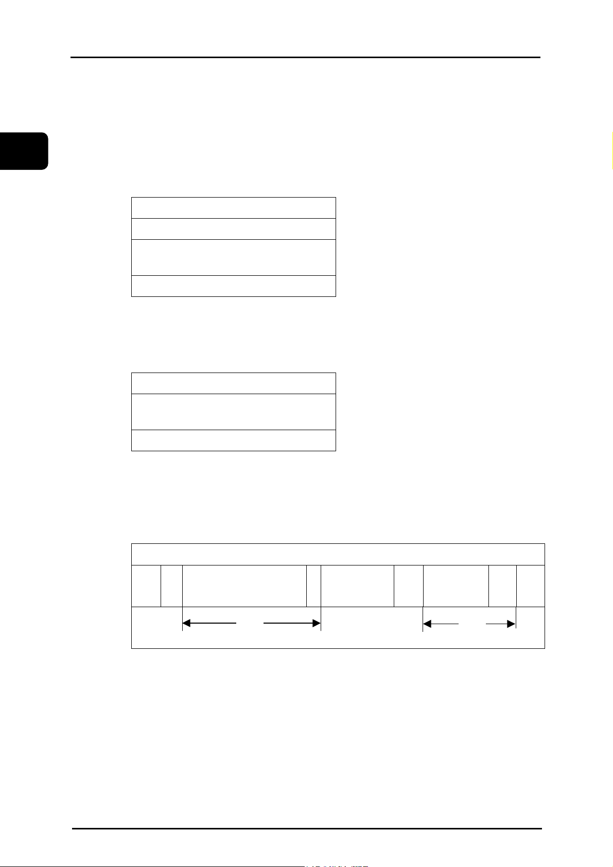
1.3 Compositiom of Word
A word is composed of an address and some digit of figures as shown below.
(Algebraic sign + or - may added before a numerical value.)
Address numerical value
(Note 1) The address uses one of the alphabetical letters.
(Note 2) The address "O" can not be used except for comments.
1.4 Numerical Values
(1) Decimal point programming
Numerical values can be input in the following two ways and set by the user
parameter (Switch 1).
Command type 1 (Standard)
Programmed command Commanded axis Actual amount (mm) Actual amount (inch)
1
Rotation axis 1 deg 1 deg
X
Feed axis 1mm 1 inch
-1000
1
1.
Command type 2 (Minimum)
Programmed command Commanded axis Actual amount (mm) Actual amount (inch)
1
1.
(Note) User parameter : Refer to Instruction manual.
Rotation axis 1 mm 1 inch
Rotation axis 1 deg 1 deg
Feed axis 0.001 mm 0.0001 inch
Rotation axis 0.001 deg 0.001 deg
Rotation axis 1 mm 1 inch
Rotation axis 1 deg 1 deg
(2) Programmable range of address
The maximum number of digits is 9.
The digits less than the minimum range are ignored.
2004/01/22 1 - 3 eTCOMNCPR1-1.doc
Page 16
1
Chapter 1 Program Composition TC-32B
1.5 Sequence Number
A sequence number (1~99999) can be used following the address N for each block.
Command format N *****;
i) A sequence number is used following the address N.
ii) A sequence number can be specified with up to 5-digit number.
(Note 1) The sequence number "N0" should not be used.
(Note 2) It is used at the head of a block.
Ex.) N0100 G90X100;
When a block has a slash (/) code at the head of block (the optional block skip is
commanded), a sequence number can be used either before or after it.
Ex.) N0100/ G90X100; or /N0100 G90X100;
(Note 3)
The order of sequence numbers is arbitary and need not be consecutive.
(Note 4)
The sequence number is recognized as numerical values. Therefore such numerical
values as 0001, 001, 01 and 1 are regarded as the same number.
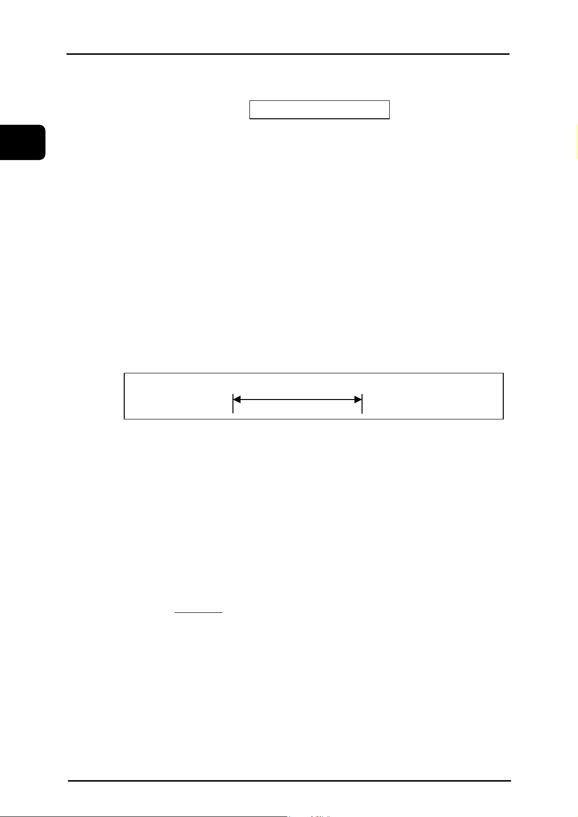
1.6 Optional Block Skip
When a block has a slash (/) code at the start and [BLOCK SKIP] key on the operation panel is
turned ON, all information in the block with the slash code is ignored during the automatic
operation.
If the [BLOCK SKIP] key is OFF, information in the block with the slash code is effective.
That is, the block with a slash code can selectively be skipped.
..... ; / N0100 G00X100 ..... ; N0101 .....
Ignore these words
(Note 1)
A slash (/) code must be put at the start of a block. If it is placed elsewhere in the
block, an alarm is generated.
This code can be also put right after a sequence number.
(Note 2)
In the single block mode during automatic operation, when the [BLOCK SKIP] key is
ON the operation does not stop at a block with a slash code, but stops at the next
block.
1.7 Control Out/In Function
For a easier look at the program, comments can be inserted in the program.
The comment is discriminated from operation by "(" and ")" at the start and the end.
( ............. )
(Ex.) N1000 G00X200 (PRO-1);
(Note)
A comment including the control out and in codes should not be longer than one
block.
2004/01/22 1 - 4 eTCOMNCPR1-1.doc
Page 17

TC-32B Chapter2 Coordinate Command
CHAPTER 2
COORDINATE COMMAND
2
2.1 Coordinate system and coordinate value
2.2 Machine zero point and machine coordinate system
2.3 Working coordinate system
2004/01/22 2 - 1 eTCOMNCPR2-1.doc
Page 18
Chapter2 Coordinate Command TC-32B
5
2.1 Coordinate system and coordinate value
Coordinate values should be set in one coordinate system to specify a tool movement.
There are two types of coordinate systems.
(i) Machine coordinate system
(ii) Working coordinate system
The coordinate values are expressed by each component of the program axes (X, Y and Z for this
unit).
2
15
Z
Y
Tool target position:
CommandedX20.Y10.Z1
10
X
0
20
eNCPR2.01.ai
2004/01/22 2 - 2 eTCOMNCPR2-1.doc
Page 19
TC-32B Chapter2 Coordinate Command
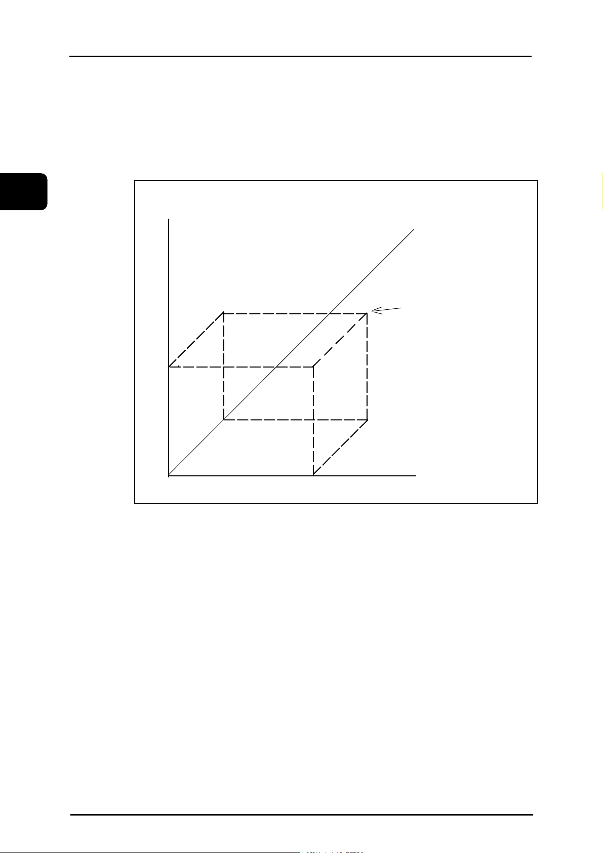
2.2 Machine Zero Point and Machine Coordinate System
(1) Machine zero point
The machine zero point is the reference point on the machine.
(2) Machine coordinate system
The coordinate systen with the machine zero point as its reference point is called the machine
coordinate system. Each machine has its own coordinate system.
Machine zero point
X axis stroke
-X
Y axis
stroke
Table
(0,0,0)
2
2.3 Working Coordinate System
The working coordinate system is used to specify a tool motion for each workpiece.
A coordinate system previously set in the "Data Bank" is once selected, programming afterward
can be easily done by specifying that coordinate system.
Each coordinate system is set by using an offset amount from the machine zero point to the
working zero position.
(Note) Data Bank : Refer to Instruction manual.
-Y
eNCPR2.02.ai
2004/01/22 2 - 3 eTCOMNCPR2-1.doc
Page 20

2
Chapter2 Coordinate Command TC-32B
( This page is a blank.)
2004/01/22 2 - 4 eTCOMNCPR2-1.doc
Page 21

TC-32B Chapter 3 Preparation Function
CHAPTER 3
PREPARATION FUNCTION
3.1 Outline of G code
3.2 Positioning (G00)
3.3 Linear interpolation (G01)
3.4 Circular/helical interpolation (G02, G03)
3.5 Circle cutting (G12, G13)
3.6 Plane selection (G17, G18, G19)
3.7 Dwell (G04)
3.8 Exact stop check (G09, G61, G64)
3.9 Programmable data input (G10)
3.10 Soft limit
3.11 Return to the reference point (G28)
3.12 Return from the reference point (G29)
3.13 Return to the 2nd/3rd/4th reference point (G30)
3.14 Selection of machine coordinate system (G53)
3.15 Selection of working coordinate system (G54~G59)
3.16 Additional working coordinate system selection
(G54.1)
3.17 Scaling (G50, G51)
3.18 Programmable mirror image (G50.1, G51.1)
3.19 Coordinate rotation function (G68, G69)
3.20 Coordinate rotation using measured results (G168)
3.21 Absolute command and incremental command
(G90, G91)
3.22 Change of working coordinate system (G92)
3.23 Skip function (G31, G131, G132)
3.24 Continuous skip function (G31)
3.25 Change of tap twisting direction (G133, G134)
3.26 High speed peck drilling cycle (G173)
3
2004/01/22 3 - 1 eTCOMNCPR3.doc
Page 22

3
Chapter 3 Preparation Function TC-32B
3.27 Peck drilling cycle (G183)
3.28 Local coordinate system function (G52)
3.29 Single direction positioning function (G60)
3.30 G code priority
2004/01/22 3 - 2 eTCOMNCPR3.doc
Page 23

TC-32B Chapter 3 Preparation Function
3.1 Outline of G code
Within 3-digit number following the address G determines the meaning of the command of the
block concerned.
The G codes are divided into the following two types.
Type Meaning
Modal
One-shot
The G code is effective until another G code in the
same group is commanded.
The G code is effective only at the block in which it is
specified.
3
2004/01/22 3 - 3 eTCOMNCPR3.doc
Page 24

Chapter 3 Preparation Function TC-32B
Group G cord Contents Modal
G00* Positioning
G01 Linear interpolation
G02 Circular/ helical interpolation (CW)
G03 Circular / helical interpolation (CCW)
Modal
G102 XZ Circular interpolation (CW)
G103 XZ Circular interpolation (CCW)
3
G202 YZ Circular interpolation (CW)
G203 YZ Circular interpolation (CCW)
G04 Dwell One-shot
G09 Exact stop check One-shot
G10 Programmable data input One-shot
G13 Circular cutting CCW One-shot
G17* XY plane selection
G18 YZ plane selection
G19 ZX plane selection
G22* Programmable stroke limit on
G23 Programmable stroke limit cancel
G28 Return to the reference point
G29 Return from the reference point
G30 Return to the 2nd /3rd/4th reference point
G31 Skip function One-shot
Modal
Modal
One-shot
G36 Coordinate calculation function (Bolt hole circle)
G37 Coordinate calculation function (Line-angle)
One-shot
G38 Coordinate calculation function (Line-angle)
G39 Coordinate calculation function (Grid)
G40* Tool dia offset cancel
G41 Tool dia offset left
G42 Tool dia offset right
The G codes with * mark indicates the modal status when the power is turned ON.
(Note1) Details of coordinate calculation functions are described in " Chapter 6 ".
(Note2) Details of tool dia offset are described in " Chapter 4 ".
2004/01/22 3 - 4 eTCOMNCPR3.doc
Modal
Page 25

TC-32B Chapter 3 Preparation Function
Group G cord Contents Modal
G43 Tool length offset +
G44 Tool length offset -
G49* Tool length offset cancel
G50* Scaling cancel
G51 Scaling
G50.1 Mirror image cancel
G51.1 Mirror image
G52 Local coordinate system
G53 Machine coordinate system selection
G54* Working coordinate system selection 1
G55 Working coordinate system selection 2
G56 Working coordinate system selection 3
G57 Working coordinate system selection 4
G58 Working coordinate system selection 5
G59 Working coordinate system selection 6
G54.1 Extended working coordinate system selection
Modal
Modal
Modal
3
One-shot
Modal
G60 Single direction positioning One-shot
G61 Exact stop mode
Modal
G64* Cutting mode
G65 Macro call One-shot
G66 Macro modal call
Modal
G67* Cancel macro modal call
G68 Coordinate rotation function
G69* Coordinate rotation function cancel
G168 Coordinate rotation using measured results
Modal
2004/01/22 3 - 5 eTCOMNCPR3.doc
Page 26

3
Chapter 3 Preparation Function TC-32B
Group G cord Contents Modal
G90* Absolute command
Modal
G91 Incremental command
G92 Working coordinate system setting One-shot
G94 Feed rate per minute
G98* Return to the initial point level
Modal
G99 Return to the R point level
G73 Canned cycle (High-speed peck drilling cycle)
G74 Canned cycle (Reverse tapping cycle)
G76 Canned cycle (Fine boring cycle)
G77 Canned cycle (Tapping cycle, synchro mode)
G78
G80* Canned cycle cancel
Canned cycle (Reverse tapping cycle, synchro
mode)
G81 Canned cycle (Drill, spot drilling cycle)
G82 Canned cycle (Drill, spot drilling cycle)
G83 Canned cycle (Peck drilling cycle)
G84 Canned cycle (Tapping cycle)
G85 Canned cycle (Boring cycle)
G86 Canned cycle (Boring cycle)
G87 Canned cycle (Back boring cycle)
G89 Canned cycle (Boring cycle)
Modal
2004/01/22 3 - 6 eTCOMNCPR3.doc
Page 27

TC-32B Chapter 3 Preparation Function
Group G cord Contents Modal
G173 Canned cycle (High-speed peck drilling cycle) One-shot
G177 Canned cycle (End mill tap cycle)
Modal
G178 Canned cycle (End mill tap cycle)
G181 Canned cycle (Double drilling cycle)
Modal
G182 Canned cycle (Double drilling cycle)
G183 Canned cycle cancel (Peck drilling cycle) One-shot
G185 Canned cycle (Double boring cycle)
G186 Canned cycle (Double boring cycle)
G189 Canned cycle (Double drilling cycle)
G100 Non-stop automatic tool change One-shot
Modal
3
2004/01/22 3 - 7 eTCOMNCPR3.doc
Page 28

Chapter 3 Preparation Function TC-32B
Group G cord Contents Modal
G120 Positioning to the measuring point One-shot
G121 Automatic measurement Corner (Boss)
G122 Automatic measurement Parallel (Groove)
G123 Automatic measurement Parallel (Boss)
G124 Automatic measurement Circle center (Hole, 3 points)
3
G125 Automatic measurement Circle center (Boss, 3 points)
G126 Automatic measurement Circle center (Hole, 4 points)
G127 Automatic measurement Circle center (Boss, 4 points)
G128 Automatic measurement Z-axis height
G129 Automatic measurement Corner (Groove)
G31 Measurement feed
G131 Measurement feed
G132 Measurement feed
G133 Changeover of tap twisting direction (CW)
G134 Changeover of tap twisting direction (CCW)
(Note)
Commands G120 to G129 are described in detail in " Option, Automatic
Measurement " in the instruction manual.
One-shot
One-shot
One-shot
2004/01/22 3 - 8 eTCOMNCPR3.doc
Page 29

TC-32B Chapter 3 Preparation Function
3.2 Positioning (G00)
A tool moves from its current position to the end point at the rapid traverse rate in
each axis direction independently. Therefore, a tool path is not always a linear line.
Command format G00 X_Y_Z_A_B_C_ ;
When the additional axis is commanded and the optional additional axis is not installed, an alarm
will occur.
In the positioning mode actuated by the G00 code, the execution proceeds to the next block after
confirming the in-position check. (Note 1)
3
eNCPR3.01.ai
(Note 1)
In-position check is to confirm that the machine detecting position is within the
specified range around the target (end) point.
(This range is set by the machine parameter for each axis.)
(Note 2)
The rapid traverse rate is set by the machine parameter for each axis.
Accordingly, rapid traverse rate cannot be specified by the F command.
2004/01/22 3 - 9 eTCOMNCPR3.doc
Page 30
Chapter 3 Preparation Function TC-32B
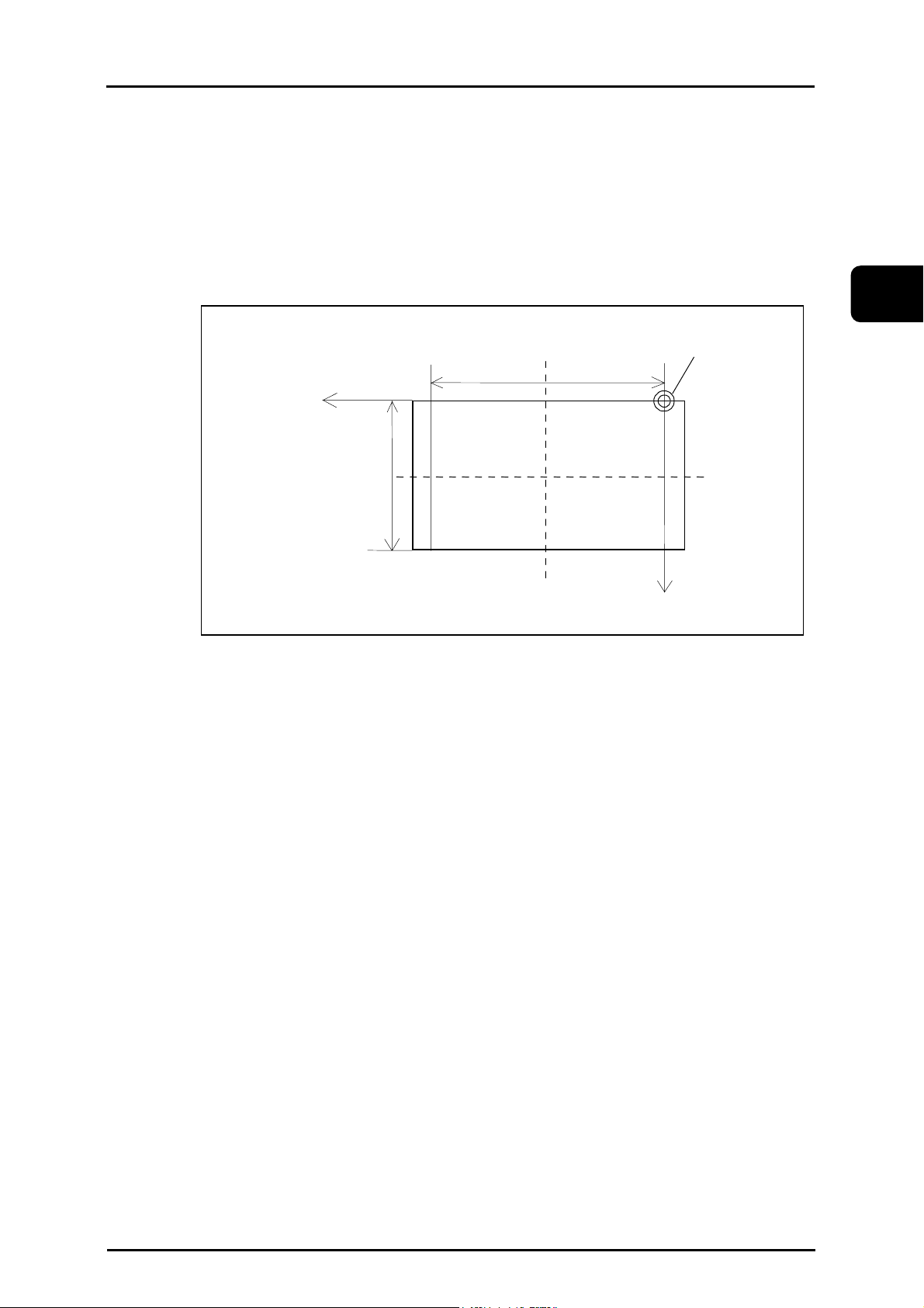
3.3 Linear interpolation (G01)
Linear interpolation moves a tool linearly from the current position to the target position at the
specified feedrate.
Command format G01 X_Y_F_ ;
Up to X,Y,X and one additional axis can be controlled simultaneously.
When the additional axis is commanded and the optional additional axis is not installed, an alarm
will occur.
3
The feedrate is commanded by the address F. Once the feedrate is commanded, it is effective until
another value is specified.
When the X, Y, and Z axes are commanded, the feedrate is determined by the value entered to mm
/ min.
When the additional axis is commanded, the feedrate is determined by the value entered to ー
/min.
End
point
Start
point
eNCPR3.2.ai
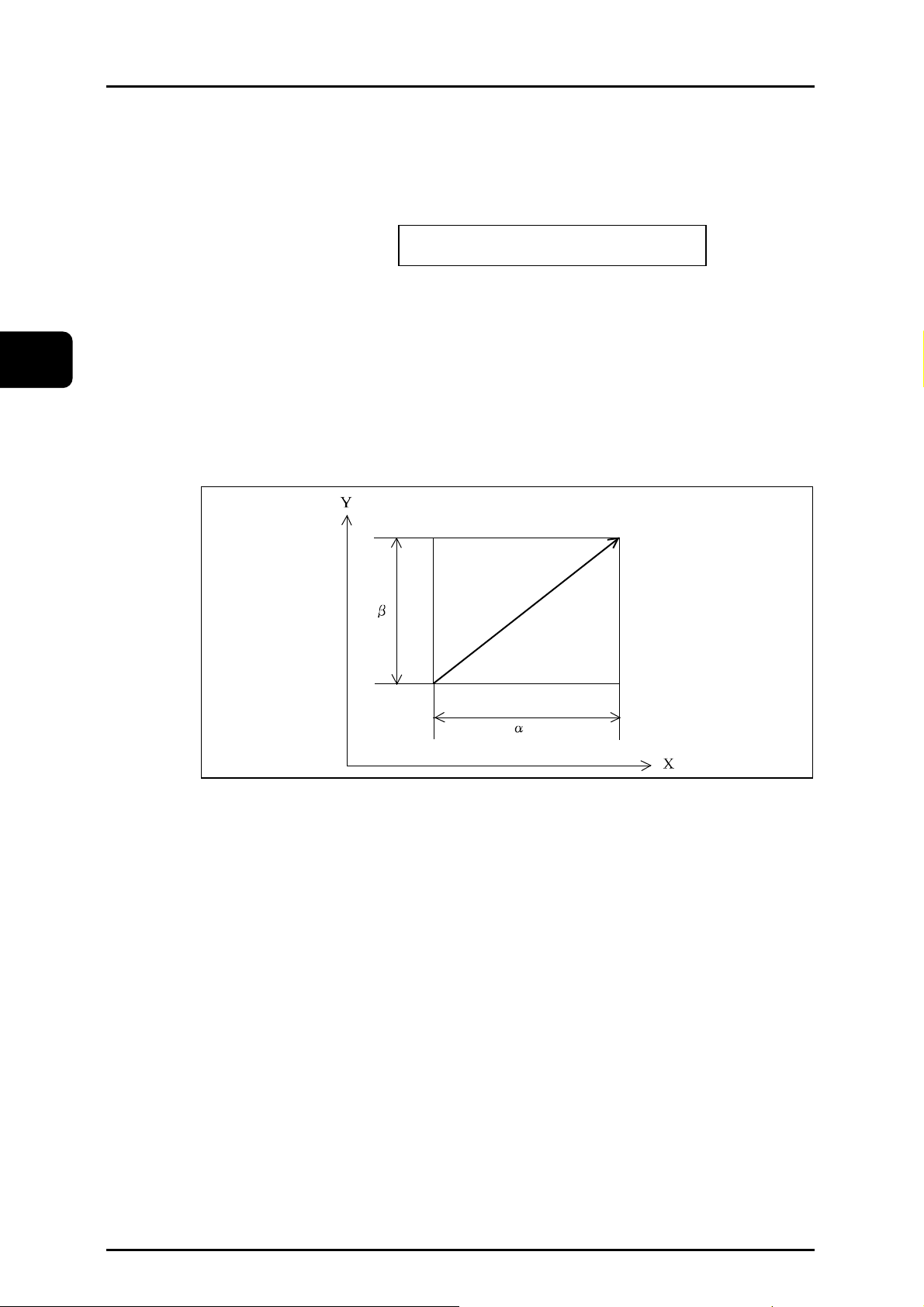
(Note 1) Feedrate along each axis is as follows:
When "G01 G91 X
Feedrate along X axis: Fx= ─── • f
L
β
Feedrate along Y axis: Fy= ─── • f
L
( L =
2004/01/22 3 - 10 eTCOMNCPR3.doc
α2 + β2 )
α Yβ Ff ;" is programmed:
α
Page 31

TC-32B Chapter 3 Preparation Function
Y
(Note2)
The example below shows linear interpolation of linear axis
α and rotation axis β.
When "G01 G91 X
Time taken for B-axis movement: Tb=
Feedrate along B axis: Fb=
Feedrate along X axis: Fx= · f
α Bβ Ff ;" is programmed:
α2+β
f
β
Tb
α
L
2
3.3.1 Chamfering to desired angle and cornering C
Chamfering to the desired angle or rounding can be performed between interpolation commands.
Chamfering
Command format G01 X_Y_, C_ ;
C: Distance from virtual corner to the chamfer start point and send
point.
3
Virtual
corner
intersection
Chamfer start point
c
(1) The corner chamfering command block and subsequent block must contain the
interpolation command (G01-G03).
When the subsequent block does not contain an interpolation or movement command, an
alarm will occur.
(2) The inserted block belongs to the corner chamfering command block. Thus, if the feed rate
differs from the corner chamfering command block and the subsequent block , the inserted
block moves at the feed rate of the corner
chamfering command block. Further, the program does not stop before the inserted block
occurs even during single block operation. (It stops after the inserted block occurs.)
(3) Tool diameter compensation applies to the configuration after corner chamfering is
performed.
Chamfer end poi
c
X
eNCPR3.03.ai
2004/01/22 3 - 11 eTCOMNCPR3.doc
Page 32

Chapter 3 Preparation Function TC-32B
)
7
(4) When the chamfering amount is longer than the chamfering command block and feeding
quantity of the subsequent block, set extended point from each blocks as "chamfer start
point" and "chamfer end point".
Example.1: Liner cutting
(4
C
(7)
(3)
3
(2)
C
(1)
(5)
When set the programmed path to (1.2.3.4.) and the block C as (2), operate to 1-5-6-7-4.
Example.2: Circular cutting
(3)
C
(6)
eNCPR3.04.ai
(4)
(
(2)
(1)
When set the programmed path to(1.2.3.4.)and the block C as (2), operate to 1-5-6-7-4.
Cornering
Command format G01 X_Y_, R_ ;
R : Radius of cornering
2004/01/22 3 - 12 eTCOMNCPR3.doc
(6)
C
(5)
eNCPR3.05.ai
Page 33

TC-32B Chapter 3 Preparation Function
n
Y
Corner-R end poi
R
Virtual corner
Corner-R start point
intersection
X
3
(1) The cornering command block and the subsequent block must contain the interpolation
command (G01-G03).
When the subsequent block does not contain an interpolation or movement command, an
alarm will occur.
(2) The inserted block belongs to the cornering command block. Thus, if the feed rate differs
from the cornering command block and the subsequent block , the inserted block moves at
the feed rate of the cornering command block. Further, the program does not stop before
the inserted block occurs even during single block operation. (It stops after the inserted
block occurs.)
(3) Tool diameter compensation applies to the configuration after cornering is performed.
(4) When the radius is longer than the corner R command block and the subsequent command
block, set extended point from each blocks as "chamfer start point" and "chamfer end
point".
Example.1: Liner cutting
(7)
R
(6)
(4)
(3)
(5)
When set the programmed path to(1.2.3.4.)and the block R as (2), operate to 1-5-6-7-4.
2004/01/22 3 - 13 eTCOMNCPR3.doc
(2)
(1)
eNCPR3.07.ai
Page 34

3
Y
Chapter 3 Preparation Function TC-32B
3.4 Circular/Helical Interpolation (G02, G03)
3.4.1 Circular interpolation
Circular interpolation moves a tool along a circular arc from the current position to
the end point at the specified feedrate.
3.4.1.1 Circular interpolation
X-Y plane
G17G02 X_ Y_ I_ J_ F_;
Command format R_
G17G03 X_ Y_ I_ J_ F_;
R_
Z-X plane
G18G02 Z_ X_ K_ I_ F_;
R_
G18G03 Z_ X_ K_ I_ F_;
R_
-Z plane
G19G02 Y_ Z_ J_ K_ F_;
R_
G19G03 Y_ Z_ J_ K_ F_;
R_
The commands are gives in the following format:
G 02 Clockwise (CW).
Rotation direction
G 03 Counterclockwise (CCW).
G90 mode X,Y,Z End point in the working coordinate system.
Distance from the start point to the end point
X
End
point
Distance between start point and arc
Clockwise and counterclockwise are the rotation direction viewed from the positive direction to
the negative direction on the Z axis of the plus direction.
G91 mode
center
Arc radius R Arc radius
Feedrate F
in the X direction.
Distance from the start point to the end point
Y
in the Y direction.
Distance from the start point to the end point
Z
in the Z direction.
Distance from the start point to the center of
I
arc in the X direction.
Distance from the start point to the center of
J
arc in the Y direction.
Distance from the start point to the center of
K
arc in the Z direction.
Feedrate in the tangential direction of circular
arc.
2004/01/22 3 - 14 eTCOMNCPR3.doc
Page 35

TC-32B Chapter 3 Preparation Function
3.4.1.2 XZ Circular interpolation
G102 X_ Y_ I_ J F_;
Command format
G103 R_
The commands are given in the following format:
G 102 Clockwise (CW).
Rotation direction
G103 Counterclockwise (CCW).
G90 mode X,Y End point in the working coordinate system.
End
point
Distance between start point and arc
G91 mode
center
Arc radius R Arc radius
Feedrate F
Distance from the start point to the end point
X
in the X direction.
Distance from the start point to the end point
Y
in the Y direction.
Distance from the start point to the center of
I
arc in the X direction.
Distance from the start point to the center of
J
arc in the Y direction.
Feedrate in the tangential direction of circular
arc.
3
Clockwise and counterclockwise are the rotation direction viewed from the positive direction to
the negative direction on the Y axis of the X-Z plane.
(Note 1)
In contrast to the XY arc case, an error occurs when the diameter compensation
command (G41, G42) or coordinate rotation command (G68, G168) is used, and the
machine stops operation.
2004/01/22 3 - 15 eTCOMNCPR3.doc
Page 36

3
Chapter 3 Preparation Function TC-32B
3.4.1.3 XZ Circular interpolation
G202 X_ Y_ I_ J F_;
Command format
G203 R_
The commands are given in the following format:
G202 Clockwise (CW).
Rotation direction
G203 Counterclockwise (CCW).
G90 mode X,Y End point in the working coordinate system.
End
point
Distance between start point and arc
G91 mode
center
Arc radius R Arc radius
Feedrate F
Distance from the start point to the end point
X
in the X direction.
Distance from the start point to the end point
Y
in the Y direction.
Distance from the start point to the center of
I
arc in the X direction.
Distance from the start point to the center of
J
arc in the Y direction.
Feedrate in the tangential direction of circular
arc.
Clockwise and counterclockwise are the rotation direction viewed from the positive
direction to the negative direction on the X axis of the Y-Z plane.
(Note 1)
In contrast to the XY arc case, an error occurs when the diameter compensation
command (G41, G42) or coordinate rotation command (G68, G168) is used, and the
machine stops operation.
2004/01/22 3 - 16 eTCOMNCPR3.doc
Page 37

TC-32B Chapter 3 Preparation Function
R
R
n
The end point of the circular arc takes either the absolute value or the incremental
value according to G90 or G91. The incremental value commands the distance from the circular
arc start point to the end point.
The circular arc center is commanded by both I,J and K according to X,Y and Z axes. I,J and K
form a vector component when viewed from the circular arc start point to the center.
It is commanded by the incremental value regardless of G90 or G91.
Absolute command;
G90G03XxYyIiJjFf;
Incremental comma
G91G03XxYyIiJjFf;
3
eNCPR3.08.ai
Instead of commanding I, J and K to specify the center of arc, the radius of arc can be used.
There are two types of circular arcs (one is less than 180° and the other is more than 180°).
When commanding a circular arc of more than 180°, put the algebraic mark "-" before the value
for the radius.
(1) G02XxYy
(2) G02XxYy
eNCPR3.09.ai
2004/01/22 3 - 17 eTCOMNCPR3.doc
Page 38

3
Chapter 3 Preparation Function TC-32B
eNCPR3.10.ai
Absolute command;
G03X-60. Y-10. I-50. J-20. F1000 ;
Incremental command;
G03X-30. Y30. I-50. J-20. F1000 ;
eNCPR3.11.ai
(1) G02X-70. Y-50. R25. F1000 ;
(2) G02X-70. Y-50. R-25. F1000 ;
(Note 1) When either I, J or K is omitted, it is regarded zero.
(Note 2) The circular arc, when its radius is zero, cannot be commanded.
(Note 3) When both X,Y and Z are omitted, the end point and the start point are
regarded identical, and:
i) 360°arc (full circle) is assumed to be commanded when the arc center
is programmed using the address I,J and K.
ii) When the address R is used, an alarm occurred.
(Note 4) The address R and "I, J and K" cannot be commanded simultaneously.
(Note 5) When the end point is not on the arc specified by start point and arc
radius, the tool moves as shown below.
2004/01/22 3 - 18 eTCOMNCPR3.doc
Page 39

TC-32B Chapter 3 Preparation Function
Transition of radius
eNCPR3.15.ai
3
eNCPR3.14.ai
(Note 6) If the ending radius is extremely larger than that of the starting radius,
an alarm will occur.
(Note 7) The G36~G39 codes cannot be commanded in the circular arc mode.
2004/01/22 3 - 19 eTCOMNCPR3.doc
Page 40

3
Chapter 3 Preparation Function TC-32B
3.4.2 Helical interpolation
Putting the other than selected plane axis command in the circular arc block permits a helical
cutting.
Command format
X-Y plane:
G17G02 X_Y_Z_ I_ J_ F_;
R_
G17G03 X_Y_Z_ I_ J_ F_;
R_
Z-Y plane:
G18G02 Z_X_Y_ K_I_ F_;
R_
G18G03 Z_X_Y_ K_I_ F_;
R_
Y-Z plane:
G19G02 Y_Z_X_ J_K_ F_;
R_
G19G03 Y_Z_X_ J_K_ F_;
R_
The F code commands the feedrate in the circular interpolation axis..
If the value of F is larger than the MAXIMUM CUTTING SPEED or the FEEDRATE SPEED set
by the machine parameter, an alarm is generated.
The feedrate in the other than selected plane axis is determined by the values of "feedrate" in the
circular interpolation axis, "end point X", "end point Y" and "end point Z". It can be calculated as
follows:
180
= × F
F
Z
× L
π × R × θ
F: Command speed (X, Y axes)
R: Radius (Start point, center)
θ:Angle
Fz: Other than selected plane of feeedrate speed.
L: Other than selected plane of feeed distance.
Ex.)
Setting following values:
F=500 (mm/min), R=10 (mm), θ=360 (°), L=2 (mm)
.
Fz = (180×2×500)/(
π×10×360) 15.9 (mm/min)
.
If the other than selected plane axis feedrate is larger than the MAXIMUM CUTTING SPEED or
FEEDRATE SPEED set by the machine parameter , an alarm is generated.
When tool dia offset command is given, an offset is applied to the selected plane.
2004/01/22 3 - 20 eTCOMNCPR3.doc
Page 41

TC-32B Chapter 3 Preparation Function
(
)
)
3.4.3 Spiral interpolation (G02, G03)
An increment or decrement per rotation is specified for the circular interpolation command to
perform spiral interpolation.
Command format
X-Y plane:
{G17}G02X_Y_I_J_Q_L_F_;
{G17}G03X_Y_I_J_Q_L_F_;
Z-Y plane:
{G18}G02Z_X_K_I_Q_L_F_;
{G18}G03Z_X_K_I_Q_L_F_;
Y-Z plane:
{G19}G02Y_Z_J_K_Q_L_F_;
{G19}G03Y_Z_J_K_Q_L_F_;
G02 : Clockwise cutting direction
G03 : Counterclockwise cutting direction
XYZ : Coordinates of end point
L : Number of rotations (positive value, decimal numbers are rounded up to the nearest
whole number). Add a decimal point, rounded off.
Example: Set "L6" for five and 1/4 rotations (5.25 rotations).
Q : Increment or decrement in radius per rotation
Setting a positive value increases the radius for each rotation.
Setting a negative value decreases the radius for each rotation.
IJK : Vector (distance and direction) from the start point to the center (the same as
circular interpolation)
F : Cutting speed
3
(Note)
Either L (number of rotations) or Q (increment/decrement in radius) can be omitted.
If there is a discrepancy between "L" and "Q" when used together, "Q" is used.
20
20
Y
100
-50
-
Start point (0,100)
End point
Distance to the center (I,J)(0,-100.
Increment/decrement in radius Q –20.0
No. of rotations L 3
X
1) G90G02X0.Y-50.I0J-100.Q-20.;
2) G90G02X0.Y-50.I0J-100.L4;
Incremental command
1) G91G02X0Y-150.I0J-100.Q-20.;
2) G91G02X0Y-150.I0J-100.L4
Setting either 1) or 2) is acceptable.
X,Y)(0,-50.
2004/01/22 3 - 21 eTCOMNCPR3.doc
Page 42

Chapter 3 Preparation Function TC-32B
Cutter compensation can be performed only in offset mode. An alarm will occur when this is
attempted in startup or cancel mode.
The setting for [Cutter compensation] is applied relative to the start point and target point specified
in the program during cutter compensation.
An alarm will occur when the programmed conical interpolation tool path or the tool path after
cutter compensation intersects or makes contact with the spiral center.
An alarm will occur when the spiral defined that over the circle radius fudge factor limit point by
the increment or decrement in radius per rotation does not match the end point.
An alarm will occur when corner CR is specified in the block immediately before a block that
performs spiral interpolation.
3
Automatic corner override is not possible for the blocks immediately before and after a block that
performs spiral interpolation.
Corner CR cannot be specified for spiral interpolation.
An alarm will occur when the radius is zero (0) or less (including negative values) as a result of
setting an increment/decrement in the radius per rotation and the number of rotations.
An alarm will occur when the radius is specified using command "R."
An alarm will occur when the increment or decrement in radius is zero (0).
An alarm will occur when setting value of selected flat as below.
Start point radius = End point radius
(1)
(2)
Start point = Center
(3)
End point = Center
Not commanded when mirror image is effective.
Not commanded when scaling image is effective.
When a cutter compensation cancel command is included in the block immediately after a block
that performs spiral interpolation and cutter compensation, the end point of the spiral interpolation
will be the position given by the vertical vector from the end point of spiral interpolation.
An in-position check is performed between the blocks immediately before and after a block that
performs spiral interpolation.
2004/01/22 3 - 22 eTCOMNCPR3.doc
Page 43

TC-32B Chapter 3 Preparation Function
3.4.4 Conical interpolation (G02, G03)
The travel command of another axis in addition to the spiral interpolation command is added and
an increment and decrement is specified for that axis per spiral rotation to perform conical
interpolation.
Command format
X-Y plane:
{G17}G02X_Y_Z_I_J_K_Q_L_F_;
{G17}G03X_Y_Z_I_J_K_Q_L_F_;
Z-X plane:
{G18}G02Z_X_Y_K_I_J_Q_L_F_;
{G18}G03Z_X_Y_K_I_J_Q_L_F_;
Y-Z plane:
{G19}G02Y_Z_X_J_K_I_Q_L_F_;
{G19}G03Y_Z_X_J_K_I_Q_L_F_;
G02 : Clockwise cutting direction
G03 : Counterclockwise cutting direction
XYZ : Coordinates of end point
L : Number of rotations (positive value, decimal numbers are rounded up to the nearest
whole number). Add a decimal point, rounded off.
Example: Set "L6" for five and 1/4 rotations (5.25 rotations).
Q : Increment or decrement in radius per rotation
Setting a positive value increases the radius for each rotation.
Setting a negative value decreases the radius for each rotation.
IJK : Set a vector from the start point to the center for two axes and the
increment/decrement in height per spiral rotation used for conical interpolation for
the remaining axis.*
3
Plane to be set Vector from start point to center
G17 X-Y plane I, J K
G18 Z-X plane K, I J
G19 Y-Z plane J, K I
F : Cutting speed
*) As long as one of IJK, L, and Q (increment/decrement in height, number of rotations,
increment/decrement in radius) is set, setting the remaining two items can be omitted.
If there is a discrepancy between "L" and "Q," the latter is used.
If there is a discrepancy between "L" and the increment/decrement in height, the latter is used.
If there is a discrepancy between "Q" and the increment/decrement in height, the former is used.
Priority Higher ← "Q" > Increment/decrement in height > "L" → Lower
Increment and decrement in
height per spiral rotation
2004/01/22 3 - 23 eTCOMNCPR3.doc
Page 44

3
Chapter 3 Preparation Function TC-32B
+Z_
25.0
25.0
(0,37.5,62.5)
25.0
25.0
-Y_
100.0
-
+X_
Example of program
Start point (0.,100.,0.)
End point (0.,-37.5,62.5)
Distance to the center (0.,-100.)
Increment/decrement in radius -25.
Increment/decrement in height 25.
No. of rotations 3
100
Example of program
Start point (0.,100.,0.)
End point (0.,-37.5,62.5)
Distance to the center (0.,-100.)
Increment/decrement in radius -25.
Increment/decrement in height 25.
No. of rotations 3
Absolute command G90G02X0 Y-37. 5Z62.5I0.J -100. F300.;
Incremental command G90G02X0 Y-137. 5Z62.5I0.J -100. F300.;
K25.
Q25.
L3
K25.
Q25.
L3
2004/01/22 3 - 24 eTCOMNCPR3.doc
Page 45

TC-32B Chapter 3 Preparation Function
Cutter compensation can be performed only in offset mode. An alarm will occur when this is
attempted in startup or cancel mode.
The setting for [Cutter compensation] is applied to the selected plane during cutter compensation,
relative to the start point and target point specified in the program.
An alarm will occur when the programmed conical interpolation tool path or the tool path after
cutter compensation intersects or makes contact with the conical center.
An alarm will occur when the circular cone defined that over the circle radius fudge factor limit
point by the increment or decrement in radius per rotation does not match the end point.
An alarm will occur when corner CR is specified in the block immediately before a block that
performs conical interpolation.
Automatic corner override is not possible for the blocks immediately before and after a block that
performs conical interpolation.
Corner CR cannot be specified for conical interpolation.
An alarm will occur when the cutter compensation direction (G41, G42) is changed between the
blocks immediately before and after a block that performs conical interpolation.
3
An alarm will occur when the radius is specified using command "R."
An alarm will occur when the increment or decrement in radius is zero (0).
An alarm will occur when setting value of selected flat as below.
(1)
Start point radius = End point radius
(2)
Start point = Center
(3)
End point = Center
Not commanded when mirror image is effective.
Not commanded when scaling image is effective.
When a cutter compensation cancel command is included in the block immediately after a block
that performs conical interpolation and cutter compensation, the end point of the conical
interpolation will be the position given by the vertical vector from the end point of conical
interpolation on the selected plane.
An in-position check is performed between the blocks immediately before and after a block that
performs conical interpolation.
2004/01/22 3 - 25 eTCOMNCPR3.doc
Page 46

Chapter 3 Preparation Function TC-32B
(
)
3.4.5 Cutter compensation procedure for spiral interpolation and conical interpolation (G02, G03)
Assuming a virtual circle with the center of the spiral interpolation as the center for the start point
and end point of the block, cutter compensation is performed for the virtual circle and then spiral
interpolation is performed based on the result of cutter compensation.
3
(1)
Program path
(3)
Intersection
(start point)
(2)
Set a virtual circle for the start point.
(4)
Intersection
start point
Set the cutter compensation for the virtual circle.
(5)
Intersection
(end point)
Set the cutter compensation for the virtual circle.
Intersection
(start point)
Set a virtual circle for the end point.
(6)
End point
Spiral interpolation and cutter compensation
with the start/end points taken as the
intersection points.
Virtual
circle for
cutter
Start point
Virtual circle for
cutter compensation
Cutter compensation
based on program path
Cutter compensation
based on virtual circle
2004/01/22 3 - 26 eTCOMNCPR3.doc
Page 47

TC-32B Chapter 3 Preparation Function
n
(2)
)
3.5 Circle Cutting (G12, G13)
Starting from the center of the circle, the tool cuts the inner side of the circle and returns to the
center of the circle.
Command format G12I_D_F_;
G13I_D_F_;
G12 : Clockwise cutting direction
G13 : Counterclockwise cutting direction
I : Radius of circle + and - symbols are ignored, and the value is always regarded as
+ (positive).
D : Compensation.
Set the tool number for compensation.
When compensation value is a plus (+), the inner side of the radius specified by
command "I" is cut.
When compensation value is a minus (-), the outer side of the radius specified by
command "I" is cut.
F : Cutting speed
[Motion (When X, Y plane selected)]
The tool moves in a circle half the distance from the center of the circle in the X-axis direction.
The rotation direction is specified to G12 or G13.
The tool completes one rotation in the rotation direction specified by G12 or G13 from start point.
It then moves in a circle half the distance from the end point of circle cutting to the center of the
circle in the rotation direction specified by G12 or G13.
3
Y
Radius
(2)
When G12 is used and the compensation is a positive value.
Y
(1)
Tool path
Compensatio
X
Tool path
工具経路
(3)
Compensation (-
(3)
X
Radius
When G13 is used and the compensation is a negative value.
2004/01/22 3 - 27 eTCOMNCPR3.doc
(1)
Page 48

Chapter 3 Preparation Function TC-32B
An alarm will occur when command "D" is omitted.
An alarm will occur when the product of the radius (command "I") minus compensation is zero (0)
or a negative value.
An alarm will occur when the circle cutting command (G12, G13) is specified together with the
cutter compensation command (G40, G41, G42) (startup or cancel mode).
Corner CR cannot be set for a block that contains the circle cutting command and the block
immediately before that block.
An alarm will occur when the radius after cutter compensation is smaller than the tool diameter.
Circle cutting is performed on the plane currently selected (G17, G18, G19).
3
The start point and end point are the same for circle cutting.
When circle cutting (G12, G13) is executed during cutter compensation (G41, G42), cutter
compensation is valid for the path compensated by command "D."
3.6 Plane Selection (G17, G18, G19)
Refer to “3.4. Circular/Helical Interpolation (G02, G03)” for more detail.
2004/01/22 3 - 28 eTCOMNCPR3.doc
Page 49

TC-32B Chapter 3 Preparation Function
3.7 Dwell (G04)
Upon completion of the previous block and in-position check, some time elapses before executing
the next block.
Command format G04 P_ ;
G04 X_ ;
P,X : Dwelling time (sec)
3.8 Exact Stop Check (G09, G61, G64)
Since acceleration and deceleration is applied independently to each axis, the actual
tool path comes inside the programmed path if each axis speed changes greatly
between the former block and the new block in the cutting feed.
The exact stop check is used to solve this problem.
: Programmed path
3
: Actual tool path
(1) Exact stop check (G09)
Command format G09 ;
This command executes an in-position check at the end of a block before proceeding to the next
block.
(Note 1) G09 is effective only in the commanded block.
(Note 2) In the positioning mode (G00) the exact stop check function is effective
regardless of this command.
(2) Exact stop check mode (G61)
Command format G61 ;
After this command is given, the exact stop check function is effective at the end of each block
until the cutting mode (G64) is commanded.
(3) Cutting mode (G64)
Command format G64 ;
When this command is given, the execution proceeds to the next block without slowing down
between the continuing two blocks. This command is effective until G61 is commanded.
(Note 1) Even during the cutting mode (G64), the exact stop check is executed in the
blocks in the positioning mode (G00) or in the exact stop check mode (G09),
or in the disconnected cutting feed block.
2004/01/22 3 - 29 eTCOMNCPR3.doc
Page 50

Chapter 3 Preparation Function TC-32B
(Note 2)
Cutting feed No traveling
3
Positioning
Cutting feed
No traveling
Cutting mode
×××
××
×××
× Exact stop check mode
When the old block is clamped while the additional axis is traveling, exact stop check is executed.
When the new block is unclamped while the additional axis is traveling, exact stop check is
executed.
2004/01/22 3 - 30 eTCOMNCPR3.doc
Page 51

TC-32B Chapter 3 Preparation Function
3.9 Programmable Data Input (G10)
(1) Input of working zero position
Command format G10L2Pn X_ Y_ Z_ A_ B_ C_ ;
n=1 : G54
n=2 : G55
n=3 : G56
n=4 : G57
n=5 : G58
n=6 : G59
When the G90 mode (absolute command) is selected, the commanded offset amount becomes
newly effective.
When the G91 mode (incremental command) is selected, the commanded offset amount is added
to the currently set offset amount to become a renewed offset amount.
When the additional axis is commanded while an optional additional axis is not installed, an alarm
will occur.
(Note) Working zero position … “Refer to “Manual Chapter 10”.
(2) Input of tool data
Tool length offset data G10L10 P_ R_ ;
Tool dia offset data G10L12 P_ R_ ;
P: offset number
R: offset amount
When the G90 mode (absolute command) is selected, the commanded offset amount becomes
newly effective.
When the G91 mode (incremental command) is selected, the commanded offset amount is added
to the currently set offset amount to become a renewed offset amount.
(Note) Tool data … Refer to “Manual Chapter 10”.
3
2004/01/22 3 - 31 eTCOMNCPR3.doc
Page 52

Chapter 3 Preparation Function TC-32B
(3) Input of tool fine offset value
When tool length /Tool diameter compensation command is issued using the program, the data of
the fine offset number corresponding to the commanded offset number is automatically reflected
in operation.
Change of tool fine offset data in program
Command format G10L11 P_ R_ ;
G10L13 P_ R_ ;
3
L11 : Fine offset of tool length
L13 : Fine compensation of tool diameter
P : Fine offset No.
Range : 1~99
R : Fine offset amount
The commanded value is added to the compensation amount in absolute
mode (G90) nd the preset value in incremental mode (G91).
Setting range +/- 99.999 mm +/- 9.9999 inch
(4) Input of measured working coordinate zero point data.
Command format G10L99 Pn X_ Y_ Z_ Q_ ;
n=1 : G54
n=2 : G55
n=3 : G56
n=4 : G57
n=5 : G58
n=6 : G59
Q : The number that stores the measured results.
After automatic measurement (G121 to G129), set the coordinate system based on
the measured position.
Input of additional working coordinate
Command format G10L99 Pn X_ Y_ Z_ Q_ ;
n : Additional working coordinate system (1 to 48).
Q : The number that stores the measured results.
Ex.) Assume that automatic measurement is carried out on the G54 coordinate system and the
measurement result turned out to be (120, 80). Set the coordinate system that this position will
be (50, 50).
(Program)
:
:
G54 G121 X100. Y100. I20. J20. Z-10. R10. ; (Corner measurement)
G10 L99 X50. Y50. ;
:
:
2004/01/22 3 - 32 eTCOMNCPR3.doc
Page 53

TC-32B Chapter 3 Preparation Function
Y
80
G54
Old working
zero point
eNCPR3.16.ai
(5) Input of tool life.
Y
50
New working
zero point
Measurement
50
120
result
X
X
3
Command format G10L97 P_ Q_ R_ W_ ;
P:Tool No.
Q : Life category
1 Non counting
2 Time (Minutes)
3 Count of hole machining (Hole)
4 Programs (Turns)
R:Life time
W : preliminary notice of life time
(Note)
If the G10 code is commanded during the tool dia offset, the tool moves to the point
where a vertical vector is formed to the last movement command of X and Y.
2004/01/22 3 - 33 eTCOMNCPR3.doc
Page 54

3
X
Chapter 3 Preparation Function TC-32B
3.10 Soft Limit
The allowable area of the tool motions can be specified in the following three ways.
(1)
Stroke setting by the parameter 2
Stroke limit setting by the parameter 1
(2)
(3)
Programmable stroke limit setting by the G22 code
3.10.1 Stroke
The maximum machine stroke is set by the parameter 2.
This should not be changed by the user
+Z
Y axis
stroke
Z axis
stroke
A xes w ork ing ar ea
Z origin
(Zero point return
position)
-
X axis stroke
-Y
(Note) Z origin is set by the machine parameter.
Machine zero poi
(0,0,0)
eNCPR3.17.ai
3.10.2 Stroke limit
The allowable area of the tool motions in each axis of the X, Y and Z is set by the user parameter.
2004/01/22 3 - 34 eTCOMNCPR3.doc
Page 55

TC-32B Chapter 3 Preparation Function
)
3.10.3 Programmable stroke limit (G22)
The allowable area of the tool motions is commanded by the program.
Command format G22 X_Y_Z_I_J_K_ ;
X : Programmable stroke limit on + direction of X axis.
Y : Programmable stroke limit on + direction of Y axis.
Z : Programmable stroke limit on + direction of Z axis.
I : Programmable stroke limit on - direction of X axis.
J : Programmable stroke limit on - direction of Y axis.
K : Programmable stroke limit on - direction of Z axis.
These are commanded with the coordinate values in the machine coordinate system.
The command is done by the absolute values regardless of the G90 and G91 codes.
(X, Y, Z
-Z
M ov abl e area
-X
(I, J, K)
-Y
eNCPR3.18.ai
(Note 1) The programmable stroke or the stroke is used as the soft limit in the
following ways.
G22: The programmable stroke is checked as the soft limit.
G23: The stroke is checked as the soft limit.
(Note 2) Right after turning ON the power, the stroke limit set by the user
parameter becomes effective.
After that, the setting by changing the user parameter or the G22
command whichever is done later becomes effective.
As for the axis which is not specified by the G22 command, the stroke
limit set by the user parameter recognized as the command value.
If the stroke limit by the user parameter is changed, however, all the
axes which are not changed become as specified by the user
parameter.
(Note 3) The stroke set by the machine parameter is always effective.
3
2004/01/22 3 - 35 eTCOMNCPR3.doc
Page 56

Chapter 3 Preparation Function TC-32B
3.11 Return to the Reference Point (G28)
Command format G28X_Y_Z_A_B_C_;
This command provides an automatic return to the reference point through an
intermediate point for commanded axes. Positioning to the reference point is made through an
intermediate point as specified by X_Y_Z_A_B_C_.
It can be 3.12 Selection of machine coordinate system (G53) commanded by either the absolute
command (G90) or the incremental command (G91).
The coordinate values of the intermediate point commanded in this block are memorized.
All the commanded axes are moved to the reference point at the rapid traverse rate by way of
intermediate point.
3
(Note 1) As for the coordinate value of the intermediate point, only the values
commanded by this G28 block are newly memorized.
The coordinate value of axis not commanded by this G28 block is
regarded as that of previous G28 block.
(Note 2) The reference point is set by the user parameter.
(Note 3) A tool motion to the intermediate point or the reference point is done by
positioning, and interpolation is not available.
(Note 4) During the single block operation, the block stops at the intermediate
point.
(Note 5) The coordinate value of the intermediate point is memorized by the
absolute value in the working coordinate system. Therefore, if the
working coordinate system is changed after the G28 is commanded, the
intermediate point is also changed to the new coordinate system.
(Note 6) When the additional axis is commanded while an optional additional
axis is not installed, an alarm will occur.
2004/01/22 3 - 36 eTCOMNCPR3.doc
Page 57

TC-32B Chapter 3 Preparation Function
3.12 Return from the Reference Point (G29)
Command format G29X_Y_Z_A_B_C_;
This command provides positioning to the commanded position through an intermediate point for
commanded axes. At an incremental command, an incremental distance from the intermediate
point must be commanded.
The commanded axes are moved to the intermediate point at the rapid traverse rate, then
positioned at the commanded point.
(Note 1) A tool motion to the intermediate point or the commanded point is done
by positioning, and interpolation is not available.
(Note 2) The tool goes through the intermediate point commanded by the G28 or
G30 whichever is given later.
(Note 3) During the single block operation, the block stops at the intermediate
point.
(Note 4) For axes whose intermediate point is not memorized using G28 or G30,
the current position is regarded as the center point.
(Note 5) When the additional axis is commanded while an optional additional
axis is not installed, an alarm will occur.
3
3.13 Return to the 2nd to 6th reference point (G30)
Command format G30P_X_Y_Z_A_B_C_;
P2 : Return to the 2nd reference point
P3 : Return to the 3rd reference point
P4 : Return to the 4th reference point
P5 : Return to the 5 reference point
P6 : Return to the 6th reference point
This command moves the axes to the 2nd, to 6th reference point in the same way as commanded
by G28.
The G29 code can be used as the same way as G28.
(Note 1) The 2nd to 6th reference points are set by the user parameter.
(Note 2) When P_ is omitted, return to the 2nd reference point is automatically
selected.
(Note 3) When the additional axis is commanded while an optional additional
axis is not installed, an alarm will occur.
3.14 Selection of machine coordinate system (G53)
The coordinate values in the machine coordinate system can be commanded in the following
ways.
Command format G53 ;
The coordinate values commanded in the same block as G53 is recognized in the machine
coordinate system.
(Note) When the incremental mode (G91) is selected, the G53 command is
ignored.
2004/01/22 3 - 37 eTCOMNCPR3.doc
Page 58

Chapter 3 Preparation Function TC-32B
3.15 Selection of working coordinate system (G54~G59)
When 6 sets of the coordinate systems for each workpiece are set in the data previously,
necessary coordinates system can be selected by commanding the G54 through G59 codes.
Command format G54
·
·
·
G59
;
3
G54 : working coordinate system 1
G55 : working coordinate system 2
G56 : working coordinate system 3
G57 : working coordinate system 4
G58 : working coordinate system 5
G59 : working coordinate system 6
3.16 Additional working coordinate system selection (G54.1)
Command format G54.1 Pn ;
Pn : Specification code for additional working coordinate
system.
n : 1~48
The working coordinate system can be selected from 48pairs using the above command.
G54 provides this function instead of G54.1.
Data setting method
1) The data can be confirmed or set on the working coordinate origin screen.
2) The data can be set by commanding G10 in the program.
Command format G10 L20 Pn X_Y_Z_ ;
Pn :Specification code for additional working
coordinate system.
n : 1~48
X,Y,Z :Setting value of workpiece origin offset value
When the absolute mode (G90) is selected, the commanded value is considered the offset value.
When the incremental mode (G91) is selected, the commanded value is added to the preset offset
value.
2004/01/22 3 - 38 eTCOMNCPR3.doc
Page 59

TC-32B Chapter 3 Preparation Function
3.17 Scaling (G50, G51)
The programmed shape can be enlarged or reduced by the desired scaling factor.
Scaling is possible using the same ratio for all axes or a different ratio for each axis.
Scaling using the same ratio for all axes
Command format G51X_Y_Z_P_;
X, Y, Z : Scaling center coordinate axes (workpiece coordinates)
P : Scaling factor
Scaling using a different ratio for each axis
Command format G51X_Y_Z_I_J_K_;
X, Y, Z : Scaling center coordinate axes (workpiece coordinates)
IJK : Scaling factor of XYZ axes
Scaling / Cancel
Command format G50;
(Note 1) Do not use other GM codes in a block where G51 is used, or an alarm
will occur.
(Note 2) Set the scaling type (scaling using the same ratio for all axes or scaling
using a different ratio for each axis) for the user parameter.
(Note 3) When the scaling factor command (P or IJK) is omitted, the scaling
parameter setting (user parameter 1) is used.
(Note 4) When the scaling center coordinates (XYZ) are omitted, the tool
position when G51 is used is regarded as the center coordinates.
(Note 5) Set the scaling factor unit (0.001 or 0.00001) for the parameter.
The valid range of the scaling factor command (P or IJK) or scaling
factor parameter is ±1 to ±999999.
Accordingly, the valid scaling range is ±0.001 to ±999.999 or ±0.00001 to
±9.99999.
3
(Note 6) The axis does not travel when scaling start (G51) or scaling cancel
(G50) is used.
2004/01/22 3 - 39 eTCOMNCPR3.doc
Page 60

Chapter 3 Preparation Function TC-32B
Example of scaling using the same ratio for all axes
3
Y
Y-axis
’
’
Machining
program
shape
Shape after
scaling
Scaling using the same ratio for all axes
P0 Scaling center
P1P2P3P4 → P1’P2’P3’P4’
X
Scaling using a different ratio for
each
axis
a / b :X-axis scaling factor
c / d :Y-axis scaling factor
O : Scaling center
X-axis
(Note 1) An alarm will occur when scaling is used for an axis that has scaling
turned off for the parameter.
(Note 2) An alarm will occur when circle cutting is specified while a different
scaling ratio is set for each axis.
(Note 3) Setting a different scaling ratio for each axis in circular interpolation
mode does not result in elliptical interpolation.
(Note 4) When a different scaling ratio is set for each axis and the radius (R) of
the arc is specified in circular interpolation mode, the larger scaling
factor of the axes forming the plane on which the arc is drawn is applied
to the radius.
Arc using command "R": The left and right command formats are equivalent.
E.g.)
G90 G00X0.Y100.; G90G00X0.Y100.;
G51X0.Y0.Z0.I2000J1000; =
G02X100.Y0.R100.F500; G02X200.Y0.R200.F500;
(Note 5) When a different scaling ratio is set for each axis and the center (I, J) of
the arc is specified in circular interpolation mode, the distance from the
start point to the center (I, J) is not subject to scaling.
Arc using commands "I" "J": The left and right command formats are
E.g.)
equivalent.
G90 G00X0.Y100.; G90 G00X0.Y100.;
G51X0.Y0.I2000J1000; =
G02X100.Y0.I0.J-100.F500; G02X200.Y0.I0.J-100.F500;
2004/01/22 3 - 40 eTCOMNCPR3.doc
Page 61

TC-32B Chapter 3 Preparation Function
Precautions for use of scaling function:
(Note 1) When scaling is invalid
Tool offset set for [Cutter compensation] and [Tool length offset] is not
subject to scaling.
Additional axes are not subject to scaling.
An alarm will occur when coordinate transformation (rotational
transformation, scaling, programmable mirror image) is performed while the
additional axis is selected by the plane selection command (G17, 18, 19).
Axis travel to the R point and ATC zero point specified by the ATC command
(G100, M6) is not subject to scaling.
Overrun of single direction positioning (G60) is not subject to scaling.
Scaling is not performed for travel amounts generated through manual
intervention.
The following are not subject to scaling in a canned cycle:
Infeed amount "Q" and relief amount "d" of deep hole cycle (G83, G73, G173,
G183) XY-axes shift "Q" of fine balling (G76) and back balling (G87).
However, an alarm will occur when the canned cycle is performed while the
Z-axis is set for scaling.
(Note 2) Traveling axes when performing scaling or programmable mirror image
When using the scaling or programmable mirror image function, the axis not
specified travels according to the specified axis or coordinates.
As a result, the following may occur:
1. The machine is not operable because the lock signal check is input for an
axis not specified.
2. The Z-axis travels because the dry run offset is automatically applied.
3. An alarm occurs because the specified axis cannot be used.
(Note 3) Cases when an alarm will occur
An alarm will occur when any reference position return related command
(G28 to G30) is used during scaling.
An alarm will occur when any coordinate change command (G10L2/20/98/99,
G22 to G23, G52 to G59, G92, G92.1) (external workpiece zero offset) is used
during scaling.
3
An alarm will occur when any automatic workpiece measurement command
(G120 to G129) is used during scaling.
An alarm will occur when any of the following is performed during scaling:
Tool change, XY or YZ circular arc (G102/103, 202/203), circular cutting spiral
interpolation or conical interpolation
An alarm will occur when a canned cycle is performed while the Z-axis is set
for scaling.
An alarm will occur when the amount of travel becomes 0 as a result of
scaling.
An alarm will occur when the corner C or R command is used during scaling.
An alarm will occur when scaling is specified in MDI operation.
(Note 4) Scaling is cancelled when M02 or M03 is used or operation is reset.
2004/01/22 3 - 41 eTCOMNCPR3.doc
Page 62

Chapter 3 Preparation Function TC-32B
Program example of mirror image using scaling function
When a negative number is specified for the scaling factor, programmable mirror image is applied.
When a negative value is specified for the scaling factor and there is only one scaling axis, CW
and CCW of circular travel will be reversed.
Program example of mirror image using scaling function
3
Y
90
60
50
40
10
10
Mirror image is applied to scaling center coordinates and programmed path while the mirror image
(G51.1) is valid.
(7)
(6)
(8)
(9)
(10)
(11)
40 50
(4)(5)
(12)
60
(3)
(2)
(1)
(13)
(14)
(15)
90
Sub program
O9000;
G00G90X60.Y60.;
G01X100.F100;
G01Y100.;
G03X60.Y60.I-30.J-30.;
M99;
Main program
N10 G00G90;
N20 M98P9000;
N30 G51X50.Y50.I-1000J1000;
N40 M98P9000;
N50 G51X50.Y50.I-1000J1000;
N60 M98P9000;
N70 G51X50.Y50.I1000J-1000;
N80 M98P9000;
X
N90 G50;
2004/01/22 3 - 42 eTCOMNCPR3.doc
Page 63

TC-32B Chapter 3 Preparation Function
3.18 Programmable Mirror Image (G50.1, G51.1)
Mirror image is applied to the program commands for the axes specified in the program.
Mirror image
Command format G51.1X_Y_Z_;
Mirror image cancel
Command format G50.1X_Y_Z_;
Mirror image setting can be applied simultaneously for the 1st to 3rd axes.
Set the mirror image axis. Omit this for axes about which a mirror image is not created.
Set the mirror image axis in workpiece coordinates.
Using G51.1 command is valid while setting a mirror image. It is regarded as an addition of
mirror axes or a change of the mirror axis coordinates.
3
Set the axis for canceling mirror image to cancel mirror image. Set the coordinates using
numerical values.
An alarm will occur when a mirror image is canceled for an axis where mirror image is not set.
Symmetric axis
(X=50)
(1)
Symmetric axis
(Y=50)
(4)
X
1006004050
60
50
40
100
0
Y
(2)
(3)
(1) Original program command
(2) When mirror axis is set for position X50.
(3) When mirror axis is set for position X50. Y50.
(4) When mirror axis is set for position Y50.
2004/01/22 3 - 43 eTCOMNCPR3.doc
Page 64

3
Chapter 3 Preparation Function TC-32B
Precautions for use of programmable mirror image:
(Note 1) When programmable mirror image is invalid
Mirror image is not applied to the positioning direction for single direction
positioning (G60).
Tool length offset is not subject to mirror image setting compensation.
The spindle rotation direction does not change during mirror image setting.
The thread cutting direction does not change during mirror image setting.
Manual intervention allows the axis travel while ignoring the mirror image
setting.
However, when there is a manual interruption during mirror processing, the
axis travels according to the path (tool path) after mirror processing.
(Note 2) Traveling axes when performing scaling or programmable mirror image
When using the scaling or programmable mirror image function, the axis not
specified travels according to the specified axis or coordinates. As a result,
the following may occur:
1. The machine is not operable because the lock signal check is input for an
axis not specified.
2. The Z-axis travels because the dry run offset is automatically applied.
3. An alarm occurs because the specified axis cannot be used.
(Note 3) Cases when an alarm will occur
An alarm will occur when mirror image (G50.1 or G51.1) is used during scaling
or rotational transformation.
An alarm will occur when coordinate transformation (rotational
transformation, scaling, programmable mirror image) is performed while the
additional axis is selected by the plane selection function (G17, 18, 19).
An alarm will occur when any reference position return related command
(G28 to G30) is used during mirror image setting.
An alarm will occur when any coordinate change command (G10L2/20/98/99,
G22 to G23, G52 to G59, G92, G92.1) (external workpiece zero offset) is used
during mirror image setting.
An alarm will occur when any automatic workpiece measurement command
(G120 to G129, etc.) is used during mirror image setting.
An alarm will occur when any of the following is performed during mirror
image setting:
Tool change, XY or YZ circular arc (G102/103, 202/203), circular cutting spiral
interpolation or conical interpolation
An alarm will occur when a canned cycle is performed while the Z-axis is set
for mirror image.
An alarm will occur when mirror image is specified in MDI operation.
(Note 4) Mirror image is cancelled when M02 or M30 is used or operation is
reset.
2004/01/22 3 - 44 eTCOMNCPR3.doc
Page 65

TC-32B Chapter 3 Preparation Function
Y
Y
Y
Y
Coordinates are calculated according to the following sequence: mirror, scaling, and then
rotational transformation. Accordingly, set these in this order in a program. Set these in the
reverse order to cancel previous settings. An alarm will occur when the specified sequence is not
followed.
When mirror image is set for only one axis on the selected plane, change the following commands:
Circular interpolation : Rotation direction
Cutter compensation : Compensation direction
Rotational transformation : Rotation direction
Circle cutting : Rotation direction
While the mirror image function is enabled, the stroke limit is checked using the coordinates after
the mirror image is created.
The axis does not travel while setting or canceling a mirror image.
(1) Axis motion when mirror image is set (1 axis setting) (G90/91)
Program
end point
(2) Axis motion when mirror image is set (2 axes setting) (G90/G91)
Program
end point
Mirror axis
Start point
Mirror center
Mirror end point
X
Mirror
end point
Program
end point
Start point
Program
end point
3
Mirror axis
Mirror end point
X
Mirror center
Mirror
end point
Start point
X
2004/01/22 3 - 45 eTCOMNCPR3.doc
Start point
X
Incorrect arc
Page 66

Chapter 3 Preparation Function TC-32B
Y
3.19 Rotational Transformation Function
(G68, G69)
The shape specified in the program is rotated.
Rotational transformation
G17
Command format G18 G68α_β_R_;
G19
3
Rotational transformation cancel
Command format G69;
αβ : Rotation center coordinates
R : Rotation angle (based on CCW)
After rotation
Rotation angle
Rotation center Before rotation
Plane section command can be omitted. The plane currently selected is valid when it is omitted.
Relationship between selected plane and αβ.
X
Selected plane
G17 X Y
G18 Z X
G19 Y Z
Rotation angle (R) is specified within the range of -360.000 to 360.0000 programming mode.
The rotation angle in incremental programming mode is determined in reference to the angle after
the previous rotational transformation, and in reference to the α axis when it is the first rotational
transformation.
2004/01/22 3 - 46 eTCOMNCPR3.doc
αβ
Page 67

TC-32B Chapter 3 Preparation Function
An alarm will occur when any reference position return related command (G27, G28, G29, G30) is
used during rotational transformation.
An alarm will occur when ccommand (G52 or G92) during rotational transformation.
An alarm will occur when any automatic workpiece measurement command (G131, G132, G120
to G129) is used during rotational transformation.
An alarm will occur when any plane selection command (G17, G18, G19) is used during rotational
transformation.
An alarm will occur when the axes forming the selected plane do not match the axis specified for
the rotation transformation center.
An alarm will occur when the rotational transformation command is used during MDI operation.
An alarm will occur when the linear axis (X, Y, Z) and rotation axis (A, B, C) simultaneous
interpolation command is used during rotational transformation.
Command "R" cannot be omitted. An alarm will occur when it is omitted.
When the rotational transformation command is used while the mirror image and scaling functions
are valid, calculation is performed according to the following sequence:
1. Change of rotational transformation center coordinates due to mirror image function
2. Change of rotation angle direction for rotational transformation when there is only one
mirror axis
3. Change of rotational transformation center coordinates due to scaling function
The rotation angle of the rotational transformation is not subject to scaling.
When a rotational transformation is performed in incremental mode, the current tool position is
regarded as the start coordinates.
Rotational transformation is cancelled when M02 or M03 is used or operation is reset.
When the center coordinates are omitted for rotational transformation, the coordinates of the
spindle’s current position are regarded as the rotation center coordinates.
Even if the rotation center and angle are changed during rotational transformation, rotational
transformation using the changed center and angle can be performed without canceling this mode.
3
Coordinates are calculated according to the following sequence: mirror image, scaling, and then
rotational transformation. Accordingly, set them in this order in a program. Set these in the
reverse order to cancel previous settings. An alarm will occur when the specified sequence is not
followed.
2004/01/22 3 - 47 eTCOMNCPR3.doc
Page 68

3
Chapter 3 Preparation Function TC-32B
3.20 Coordinate rotation using measured results (G168)
Command format G168 X_Y_Q_;
X,Y : Rotation center coordinate value.
Q : Selects the desired measured result by setting "1"
to "4".
When the selection is omitted, the setting is
considered to be "1".
The coordinate system commanded in the absolute value is always recognized.
When this setting is omitted, the position in which the block has shifted from G69 to G168 (or
G68) is considered the center.
The coordinate is rotated using the angle obtained from the measurement.
Other features are the same as those for the coordinate rotation function.
3.21 Absolute command and incremental
command (G90, G91)
The axis movement amount can be specified by either the absolute command or the
incremental command.
(1) Absolute command (G90)
This is commanded by the G90 code. It specifies an end point of the block in the working
coordinate system.
(2) Incremental command (G91)
This is commanded by the G91 code. It specifies a distance from the start point to the end point in
the block.
Star t p oi nt
Absolute command
G90 X90 Y70 ;
Incremental command
G91 X60 Y40 ;
End point
eNCPR3.19.ai
2004/01/22 3 - 48 eTCOMNCPR3.doc
Page 69

TC-32B Chapter 3 Preparation Function
(3) When additional axis is commanded
1. Absolute command (e.g., B axis)
When B STROKE of user parameter is set to 1: YES, the B axis rotates to the commanded
•
angle.
•
When B STROKE of user parameter is set to 0: NO, the B axis rotates in the direction
closer to the commanded angle.
When the commanded angle is the same both in the positive and negative directions (e.g. 180
degrees.), the B axis rotates in the positive direction.
•
When B STROKE of user parameter is set to 0: NO, even a larger angle than 360 degrees
is commanded, this is handled within 360 degrees.
When B STROKE is set to 0: NO
Machine position
Absolute position
Ex.3
Ex.1
Ex.2
eNCPR3.20.ai
(ex.1) When B0.000 is entered, the axis rotates 90 degrees in the negative direction
(ex.2) When B180.000 is entered, the axis rotates 180 degrees in the positive direction
(ex.3) When B0.000 is entered, the axis rotates 90 degrees in the negative direction
B-axis machine zero point
B-axis work zero point (Set to 90 degrees in this example)
· B-axis current position before traveling (Angle)
3
2. Incremental command
Regardless of the setting of B STROKE (1: YES or 0: NO) of user parameter ,
the axis rotates for the commanded angle.
However, when B STROKE of user parameter is set to 1: YES, STROKE OVER
or LIMIT OVER alarm may occur due to stroke and stroke limit control.
2004/01/22 3 - 49 eTCOMNCPR3.doc
Page 70

Chapter 3 Preparation Function TC-32B
3.22 Change of workpiece coordinate system
(G92)
Change of workpiece zero position can be commanded as follows:
Command format G92X_Y_Z_A_B_C_;
This command shifts the zero position in the working coordinate system so that the current tool
position becomes to the commanded coordinate values.
3
Y
Shift
Old workpiece zero position
Y'
Tool position
X
New zero position
X
eNCPR3.21.ai
Ex.) The absolute coordinate of the tool position changes to (80, 60) from the current position (150,
100) as commanded "G92 X80. Y60.;"
(Note 1) The commanded coordinate values are always absolute regardless of
G90 and G91.
(Note 2) The working coordinate values of the not commanded axes do not
change.
(Note 3) The current working zero position shifts when G92 is executed, and
other working zero positions also shift the same amount accordingly.
2004/01/22 3 - 50 eTCOMNCPR3.doc
Page 71

TC-32B Chapter 3 Preparation Function
a
New G54
working zero position
Old G54 working zero position
In the above figures, G92 is commanded in the coordinate system of G54.
When the working zero position of G54 shifts, the other working zero positions of G55 through
G59 also shift the same amount as G54.
(Note 4) When G92 is commanded during the tool dia offset, the tool moves to
the position where the offset vector is formed vertically to the X/Y
movement direction. And the working coordinate system is created with
the current position in the program as commanded by G92.
Old G55 working zero position
G00X50. Y50. G41D1
G01Y100. F1000;
X50
..........
New G55
working zero position
eNCPR3.22.ai
3
New zero position
Working zero positi on
(Note 5) When G92 is commanded during the tool length offset, the working
coordinate system is created so that the target value of the
programmed Z axis becomes the same as commanded by G92.
2004/01/22 3 - 51 eTCOMNCPR3.doc
Programed p
Tool path
eNCPR3.23.ai
Page 72

Chapter 3 Preparation Function TC-32B
Spindle end face
Tool top point
3
The target value in the program becomes the
same as commanded by G92.
(Note 6) When the additional axis is commanded while an optional additional
axis is not installed, an alarm will occur.
3.23 Skip function (G31,G131,G132)
The tool moves linearly (linear interpolation) at the specified feedrate from the current position to
the target position or until the detection signal turns ON.
Command format G31 X_Y_Z_F_ ;
G131 X_Y_Z_F_ ;
G132 X_Y_Z_F_ ;
Up to three axes (X,Y,Z) can be controlled simultaneously.
The feedrate is set by address F. Once the feedrate is set, it is effective until another value is
specified.
For G131, the SENSOR SIGNAL OFF alarm occurs when the tool has moved to the target
position without the detection signal turning ON.
For G31, G132, an alarm does not occur.
As the coordinate value when detective signal turns ON is stored in system
variables(#5061~#5063) of the custom macro, it can be used in the custom macro.
Note 1: An alarm occurs when tool dia offset mode is selected.
Note 2: The tool does not move during a dry run state.
Note 3: The tool moves to the target position during a machine lock state.
Note 4: When the detection signal is already ON, the tool stops at the current
position.
2004/01/22 3 - 52 eTCOMNCPR3.doc
Page 73

TC-32B Chapter 3 Preparation Function
3.24 Continuous skip function (G31)
The tool moves linearly (linear interpolation) at the specified feedrate from the current position to
the target position. If the detection signal turns ON in the meantime, the coordinate value when the
detective signal turns ON is stored in the system variables(#5061~#5063) of custom macro.
Command format G31P90X_F_ ;
G31P90Y_F_ ;
G31P90Z_F_ ;
Note 1: An alarm occurs when tool dia offset mode is selected.
Note 2: The tool does not move during a dry run state.
Note 3: The tool moves to the target position during a machine lock state.
0.
3.25 Change of tap twisting direction (G133,G134)
G134 I_
Command format Z_ S_;
G133 J_
3
Commanding G133 and G134 rotates the spindle clockwise and counterclockwise respectively.
Z: Z axis target position.
Conforms to G90/G91 mode.
I: Thread pitch
J: No, of thread
S: Spindle speed
The Z axis is moved synchronousy with the spindle.
These are one shot G codes.
Command G133/G134 each time even for continuous operation.
2004/01/22 3 - 53 eTCOMNCPR3.doc
Page 74

3
Z
Chapter 3 Preparation Function TC-32B
3.26 High speed peck drilling cycle (G173)
Command format G173 X _ Y _ Z _ R _ Q _ F _ ;
R point
Q
d
point
Q
d
rapid feed
cutting feed
eNCPR5.19.ai
2004/01/22 3 - 54 eTCOMNCPR3.doc
Page 75

TC-32B Chapter 3 Preparation Function
ed
3.27 Peck drilling cycle (G183)
Command format G183 X _ Y _ Z _ R _ Q _ F _ ;
This is cycle where return operation is removed from G83.
R point
Q
3
Z point
d
Q
d
dwelling for P sec
rapid f eed
cutting fe
eNCPR5.23.ai
2004/01/22 3 - 55 eTCOMNCPR3.doc
Page 76

3
Chapter 3 Preparation Function TC-32B
3.28 Local coordinate system function (G52)
Command format G52 X_ Y_ Z_ A_ B_ C_ ;
X, Y, Z, A, B, C: Amount of shift from workpiece coordinate zero point
Operation will be the same regardless of G90 or G91.
Amount of shift is applied only to the specified axis.
1) Executing this command creates a local coordinate system in all coordinate systems from
G54 to G59.
2) The workpiece coordinate system does not vary even when this command is executed.
3) The local coordinate system of the specified axis is canceled when G92 command is
executed.
4) An error will occur when this command is executed during coordinate rotation.
5) When this command is executed during tool compensation, the tool moves to the position
where the offset equivalent to the tool diameter is vertically applied to the end point of the
previous block.
6) The local coordinate system is canceled when any of the following operations are
performed:
G52 is used to instruct for the command value of the axis.
G92 is used
M02 (M30) is used.
2004/01/22 3 - 56 eTCOMNCPR3.doc
Page 77

TC-32B Chapter 3 Preparation Function
3.29 Single direction positioning function (G60)
Command format G60 X_Y_Z_A_B_C_ ;
X, Y, Z, A, B, C: Command value of the axis for which single direction
positioning is performed.
Coordinate of end point for G90 and travel amount for G91
Single stop does not
Start point
Start point
Stop
End point
Travel amount
eNCPR3.25.ai
Operation is reset.
When the above command is executed, the axis moves from the end point for the preset travel
amount, and then moves to the end point.
G60 is a one shot command and the axis travel path is the same as that for G00.
The travel amount is set for the user parameter.
1) Single direction positioning is not performed for the Z-axis during a canned cycle, or the
XY-axes when they are moving for the preset amount of shift in the G76 and G87 cycles.
2) Single direction positioning is not performed for any axis that does not have the travel
amount set for the parameter.
3) Single direction positioning is performed even when 0 is specified for the travel amount.
4) An error will occur when G60 is used during tool compensation.
3
2004/01/22 3 - 57 eTCOMNCPR3.doc
Page 78

3
Chapter 3 Preparation Function TC-32B
3.30 G code priority
(1) Executed correctly.
(2) Error
(3) The last G command is effective.
(4) One-shot is executed and the modal is updated.
(5) One-shot is executed and the modal is updated, but an error occurs when circle arc is
commanded.
(6) Executed when the modal is G0 or G01, but an error occurs when circle arc is commanded.
(7) G22 is executed when G22 is commanded and the model for G0 group is updated.
Both are executed when G23 is commanded.
(8) An error occurs when circular command is output.
(9) An error occurs while circular arc mode is selected.
(10) The one commanded after the block is executed.
When G80 group is executed, the model for G00 group is updated.
When G0 group is executed, G80 group is canceled.
(11) An error occurs, but both are executed when commanded with G80.
(12) One shot execution, modal cancellation.
(13) Executed correctly except when the XZ or YZ arc command is executed.
(14) An error occurs, but both are executed when commanded with G69.
(15) G00 group is executed. G80 is model cancelled.
(16) One shot is executed and the model is updated, but an error occurs when G54P is used.
(17) Both are executed when the G0 group and model updated are simultaneously with G80.
An error occurs when used simultaneously with G54P.
(18) An error occurs when G54P is used.
(19) An error occurs when G102, G103, G202, G203 are used.
(20) Only effect for G17.
(21) An error occurs when G102~G203, without G17 of XY flat selection.
(22) An error occurs when already set to the measurement rotation mode.
Only G17 is able to command for G168.
(23) An error occurs when Z axis is mirror mode.
(24) An error occurs when changing for during the measurement.
(25) G68 is effective. G168 is error.
2004/01/22 3 - 58 eTCOMNCPR3.doc
Page 79

TC-32B Chapter 3 Preparation Function
Command the same block (Model-Model)
1
2
2
2
2
2
1
1
2
2
2
2
1
2
1
2
2
2
1
3
3
1
1
G177
G98
G94
G90
G80
G73
G69
G68
G168
G67
G66
G61
G54 P
G54
G51.1
G50.1
G51
G50
G49
G43
G44
G41
G42
G40
G23
G22
G18
G19
G17
G2
G3
G0
G1
10
10
1
1
1
1
1
1
1
1
1
1
2
2
1
1
1
1
1
2
2
1
1
1
1
1
1
1
1
1
1
1
1
1
1
2
2
1
1
1
1
1
2
2
1
1
1
1
1
1
1
1
1
1
1
1
1
1
2
2
1
1
1
1
1
2
2
1
1
1
1
1
1
1
1
1
1
1
1
2
2
2
2
1
1
1
2
2
1
1
3
10
10
1
2
2
2
2
2
1
1
2
2
2
2
1
2
1
2
2
10
10
1
1
1
1
1
1
1
2
2
1
2
2
2
2
1
1
1
4
19
2
2
2
2
1
1
1
1
1
1
4
19
4
4
2
2
2
2
1
8
1
8
1
1
1
1
1
1
7
7
1
19
1
21
3
3
3
3
2
2
2
2
2
2
2
2
2
2
1
1
22
22
2
2
2
2
2
2
2
2
2
2
2
2
2
2
2
2
2
2
2
2
2
2
2
2
1
1
1
1
1
1
1
1
2
2
1
1
1
1
1
1
1
1
1
1
2
2
2
2
1
1
1
1
1
1
1
1
2
2
2
2
2
2
2
2
2
2
2
2
2
2
3
3
2
2
2
2
2
2
2
2
2
2
3
3
2
2
2
2
2
2
2
2
3
3
2
2
2
2
2
2
2
2
3
3
1
1
2
2
1
1
3
3
1
1
2
2
1
1
3
3
2
2
2
2
3
3
1
1
2
2
3
3
1
1
3
3
2
2
3
3
3
3
3
3
1
2
2
2
2
2
2
1
1
3
3
3
3
3
2
2
2
3
2
2
3
2
3
3
3
1
3
3
3
3
1
1
1
3
1
3
3
3
3
G0,G1
G2,G3
G17
G18,G19
G22
G23
G40
G41,G42
G43,G44
G49
G50
G51
G50.1
G51.1
G54
G54 P
G61
G66
G67
G68,G168
G69
G73
G80
G90
G94
G98
G177
2004/01/22 3 - 59 eTCOMNCPR3.doc
Page 80

3
Chapter 3 Preparation Function TC-32B
Command the same block (Model-One-shot)
2
1
2
2
2
2
2
2
2
1
1
2
2
2
2
2
2
2
G177
G98
G94
G90
G80
G73
G69
G68
G168
G67
G66
G61
G54 P
G54
G51.1
G50.1
G51
G50
G49
G43
G44
G41
G42
G40
G23
G22
G18
G19
G17
G2
G3
G0
G1
1
1
1
1
1
1
1
1
1
1
1
2
1
1
1
1
1
1
1
1
1
1
1
1
1
1
1
2
1
1
1
1
1
1
1
1
1
1
1
1
1
1
1
2
1
1
1
1
1
1
1
1
4
4
4
4
4
1
4
2
4
4
4
4
2
1
2
2
2
2
2
2
2
1
1
2
2
2
2
2
1
1
1
1
1
1
1
1
1
1
1
2
1
1
1
1
2
1
2
1
2
2
2
2
2
1
2
2
2
2
2
2
2
2
2
2
2
2
2
2
2
2
2
2
2
2
2
2
2
2
2
2
2
2
2
2
2
2
2
2
2
2
2
2
1
1
1
1
1
1
1
1
1
1
1
2
1
1
1
1
2
1
2
1
2
2
2
2
1
4
1
2
1
1
1
1
1
1
1
1
1
1
1
1
1
4
1
2
1
1
1
1
2
1
2
2
2
2
2
2
2
2
2
2
2
2
2
2
2
1
2
2
2
2
2
2
2
2
2
2
2
2
2
2
2
2
2
2
2
2
2
2
2
2
2
2
2
2
2
2
2
2
2
2
2
2
2
2
2
2
2
2
2
2
2
2
2
1
2
2
1
1
1
1
2
1
1
2
2
1
1
1
2
1
2
2
1
1
1
1
2
1
1
2
2
1
1
1
2
1
2
2
2
2
2
2
2
1
2
2
2
2
2
20
2
1
2
2
2
2
2
2
2
1
2
2
2
1
2
2
2
1
2
2
2
2
2
2
2
1
2
2
2
2
2
2
2
1
2
2
2
2
2
2
2
1
2
2
2
2
2
2
2
1
2
2
2
2
2
2
2
1
1
2
2
2
2
2
2
1
2
2
2
2
2
2
1
1
2
2
2
20
4
1
4
4
4
4
4
2
4
1
4
2
4
1
4
4
4
4
4
4
4
1
4
2
2
20
4
4
4
2
4
4
4
4
3
1
1
1
1
1
1
1
1
1
4
4
3
2
2
3
1
1
1
2
2
2
2
2
2
2
2
2
1
1
1
1
1
2
1
1
1
2
2
2
2
2
2
2
2
2
2
2
2
1
2
1
1
2
1
2
2
2
2
2
2
2
2
2
2
2
2
2
2
2
2
20
20
4
4
10
4
4
10
G4G9G10
G12
G28
G30
G31
G36
G52
G53
G60
G65
G92
G100
G120
G121
G131
G133
G173
2004/01/22 3 - 60 eTCOMNCPR3.doc
Page 81

TC-32B Chapter 3 Preparation Function
Command the same block (One-shot -One-shot)
2
1
2
2
2
2
2
2
2
1
1
2
2
2
2
2
2
2
G173
G133
G131
G121
G120
G100
G92
G65
G60
G53
G52
G36
G31
G30
G28
G12
G10
G9
G4
2
2
2
2
2
2
2
2
1
2
2
2
2
2
2
2
1
3G4
1
2
2
2
2
2
2
2
1
2
2
2
2
2
2
1
2
2
2
2
3
2
2
1
2
2
2
2
2
2
1
2
2
2
2
2
2
2
1
2
2
2
2
2
3
1
2
2
2
2
2
2
2
1
2
2
2
2
3
1
2
2
2
2
2
2
2
1
2
2
2
3
1
2
2
2
2
2
2
2
1
2
2
3
2
2
2
2
2
2
2
2
2
2
3
1
2
2
2
2
2
1
2
1
3
1
1
1
1
1
1
1
1
3
1
2
2
2
2
2
2
3
1
2
2
2
2
2
3
1
2
2
2
2
3
1
2
2
3
3
1
2
2
3
3
1
2
3
1
3
3
3
2
3
3
3
G9
G10
G12
G28
G30
G31
G36
G52
G53
G60
G65
G92
G100
G120
G121
G131
G133
G173
2004/01/22 3 - 61 eTCOMNCPR3.doc
Page 82

Chapter 3 Preparation Function TC-32B
Command during Model
3
G0G1G2G3G17 G18
G0,G1 1111111111 1 1 1 1 111 1 115111115
G2,G3 11911119111191 191 1 11119115111115
G17 11 11121111 1 1 1 1 111 2 111111 1
G18,G19 11 11121111 1 1 1 1 111 2 121111 2
G22 1111 111112 1 2 1 1 111 1 111111 1
G23 1111 111112 1 2 1 1 111 1 111111 1
G40 111111 1111 1 1 1 1 111 1 111111 1
G41,G42 111111 1111 1 1 1 1 121 1 121111 2
G43,G44 11111111 11 1 1 1 1 111 1 111111 1
G49 11111111 11 1 1 1 1 111 1 111111 1
G50 1111111111 1 1 1 1 111 2 111111 1
G51 1111111111 1 1 1 1 111 2 111111 1
G50.1 111111111112 1 1 111 2 111111 1
G51.1 111111111112 1 1 111 2 111111 1
G54 111111111112 1 2 111 1 111111 1
G54.1 111111111112 1 2 11 1 1 111111 1
G61 111111111111 1 1 1 1 11 1 111111 1
G66 111111121111 1 1 1 1 1 1 111111 1
G67 111111111111 1 1 1 1 1 1 111111 1
G68,G168 1112511111111 1 1 1 1 111 11111 1
G69 111111111111 1 1 1 1 111 11111 1
G73 111211121111 1 231 1 111 1 1 111
G80 111111111111 1 1 1 1 111 1 1 111
G90 111111111111 1 1 1 1 111 1 111 11 1
G94 111111111111 1 1 1 1 111 1 1111 1 1
G98 111111111111 1 1 1 1 111 1 11111 1
G177 111211121111 1 231 1 111 1 1 111
G4 111111111111 1 1 1 1 111 1 111111 1
G9 111111111111 1 1 1 1 111 1 111111 1
G10 11111111111241 241 1 111 1 111111 1
G12 111111111112 1 2 1 1 111 1 111111 1
G28 111111121112 1 2 1 1 111 2 111111 1
G30 111111121112 1 2 1 1 111 2 111111 1
G31 111111121112 1 2 1 1 111 2 121111 2
G36 121211121112 1 2 1 1 111 2 111111 1
G52 111111111112 1 2 1 1 111 2 111111 1
G53 111111111112 1 2 1 1 111 1 111111 1
G60 111111111112 1 2 1 1 111 1 111111 1
G65 111111111111 1 1 1 1 111 1 111111 1
G92 111111111112 1 2 1 1 111 2 111111 1
G100 111111111112 1 2 1 1 111 1 112111112
G120 111111121112 1 2 1 1 111 2 111111 1
G121 121211121112 1 2 1 1 111 2 111111 1
G131 111111121112 1 2 1 1 111 2 121111 2
G133 111211121111 1 231 1 111 1 111111 1
G173 111211121111 1 231 1 111 1 111111 1
G22 G23 G40 G41
G19
G43
G49 G50 G51 G50.1 G51.1 G54 G54.1 G61 G66 G67 G68
G42
G44
G69 G73 G80 G90 G94 G98 G177
G168
2004/01/22 3 - 62 eTCOMNCPR3.doc
Page 83

TC-32B Chapter4 Preparation function (Tool offset function)
(
)
CHAPTER 4
PREPARATOION FUNCTION
TOOL OFFSET FUNCTION
4.1 Tool dia offset (G40, G41, G42)
4.2 Tool length offset (G43, G44, G49)
4
2004/01/22 4 - 1 eTCOMNCPR4.doc
Page 84

4
Chapter4 Preparation function (Tool offset function) TC-32B
4.1 Tool dia offset (G40, G41, G42)
4.1.1 Tool dia offset function
Programming is done according to the actual workpiece form, but this function
enables the tool to move along the path with an offset from actual workpiece form, which is
equivalent to the used tool radius.
G41
Command format Dn;
G42
G codes and D code used for tool dia offset
G40 : Tool dia offset cancel (Effective at power ON)
G41 : Left offset along tool path
G42 : Right offset along tool path
G41 and G42 command an offset mode, while G40 commands a cancel of the offset mode.
eNCPR4.01.ai
Dn : Tool offset number (n=0~99)
The offset amount of D0 is always zero.
The offset amount is set on the tool data setting screen.
(Note1) Refer to "Chapter 10" in the Instruction Manual for details of the tool
data setting screen.
(Note2) When a command without X and Y axis travel of more than three blocks
or a command with a travel amount of zero (0) is given in tool dia. offset
mode, excessive cutting or insufficient cutting may occur, respectively.
4.1.1.1 Tool dia fine compensation
When G41and G42 are commanded in the program, the tool dlameter fine compensation value
corresponding to the commanded tool number is added tothetool diameter compensation value.
The tooldiameter fine compensation value is placed on the tool list screen.
2004/01/22 4 - 2 eTCOMNCPR4.doc
Page 85

TC-32B Chapter4 Preparation function (Tool offset function)
4.1.2 Cancel mode
The system enters the cancel mode right after the power is turned ON or the
[RESET] key is pressed.
In the cancel mode, the path of the tool center coincides with the programmed path.
Terms and symboles for tool dia offset
1. Inside and outside
If the angle measured on workpiece side is larger than 180 ー, it is called "Inside".
If the angle measured on workpiece side is smaller than 180 ー, it is called
“Outside".
4
eNCPR4.02.ai
: Programmed path
: Tool center path
: Auxiliary line
L : Linear lin
C : Circular line
D : Tool dia offset amount
θ : Tool dia offset angle
T : Circular tangent
CP : Cross point
S : Single block stop point
2004/01/22 4 - 3 eTCOMNCPR4.doc
Page 86

4
Chapter4 Preparation function (Tool offset function) TC-32B
4.1.3 Start-up
When a block which satisfies all the following conditions is executed in the cancel mode, the
system enters the offset mode. The control in this operation is called the start-up.
a) G41 or G42 is commanded.
b) The tool offset number is not zero.
b) The movement command other than circular arc (G02 or G03) is given on the
X-Y plane,and the movement distance is not zero.
(Note 1) In the case of circular arc command, an alarm is generated.
(Note 2) Command the G0, G1, G2, or G3 first before command the G41/G42.
4.1.3.1 Inside cutting (180 ≤ θ )
Linear-Linear
Linear-Arc
2004/01/22 4 - 4 eTCOMNCPR4.doc
Page 87

TC-32B Chapter4 Preparation function (Tool offset function)
4.1.3.2 Outside cutting
(a)Type 1 : Linear - Linear
Type 1 : Linear - Arc
(b)Type 2 : Linear - Linear
Type 2 : Linear - Arc
4
(Note 1) Type 1 and 2 can be selected in parameter 1 for start-up and cancel
motions.
(Note 2) If the angle is close to 180˚ (179˚
selected,actual movement will be type 1.
2004/01/22 4 - 5 eTCOMNCPR4.doc
≤ θ < 180˚) while type 2 is being
Page 88

4
Chapter4 Preparation function (Tool offset function) TC-32B
4.1.3.3 Outside cutting ( θ < 90°)
(a)Type 1 : Linear - Linear
Type 1 : Linear - Arc
(b)Type 2 : Linear - Linear
Type 2 : Linear - Arc
(Note 1) Type 1 and 2 can be selected in parameter 1 for start-up and cancel
motions.
(Note 2) If the angle is close to 1°(θ
actualmovement will be type 1.
2004/01/22 4 - 6 eTCOMNCPR4.doc
≤1°) while type 2 is being selected,
Page 89

TC-32B Chapter4 Preparation function (Tool offset function)
4.1.4 Offset mode
A tool movement command in the offset mode includes a positioning, a linear
interpolation, a circular interpolation and a helical interpolation.
4.1.4.1 Inside cutting
Linear - Linear
Arc - Linear
4
Linear - Arc
Arc – Arc
2004/01/22 4 - 7 eTCOMNCPR4.doc
Page 90

4
Chapter4 Preparation function (Tool offset function) TC-32B
(Note 1) When going around at a narrow angle (there is α < 1˚) no cross point of 2
perpendicular lines from programme lines, so that tool center path will be
exceptionally as follows;
Linear - linear
Linear –Arc
It will be processed in the same procedure as above in case of Arc-Linear and Arc-Arc.
(Note 2) When (180˚
Linear - linear
It will be processed in the same procedure as above in case of Arc-Linear, Linear-Arc and ArcArc.
≤ θ< 181˚), tool center path will be as follows;
2004/01/22 4 - 8 eTCOMNCPR4.doc
Page 91

TC-32B Chapter4 Preparation function (Tool offset function)
4.1.4.2 Outside cutting (90°≤θ<180°)
Linear - Linear
Linear - Arc
4
Arc - Linear
Arc - Arc
2004/01/22 4 - 9 eTCOMNCPR4.doc
Page 92

4
Chapter4 Preparation function (Tool offset function) TC-32B
(Note 1) When 179˚ <θ<180˚, tool center path will be as follows;
Linear -Linear
It will be processed in the same procedure as above in case of Arc - Linear, Linear - Arc and
Arc - Arc.
4.1.4.3 Outside cutting ( θ<90˚ )
Linear – Linear
Arc – Linear
2004/01/22 4 - 10 eTCOMNCPR4.doc
Page 93

TC-32B Chapter4 Preparation function (Tool offset function)
A
p
Linear - Arc
Arc - Arc
4.1.4.4 Exceptional case
There is no cross point at inside cutting.
larmed sto
4
As above figure shows, the cross point of the arcs is present if the offset value is small, but it may
be disappear if the offset value becomes large.
In this case, alarm occurs in the preceding block, and the machine stops.
2004/01/22 4 - 11 eTCOMNCPR4.doc
Page 94

4
Chapter4 Preparation function (Tool offset function) TC-32B
4.1.5 Offset cancel
When the command satisfying all the conditions as shown below is executed in the offset mode,
the offset cancel mode becomes effective.
The tool motion in this status is called an offset cancel.
a) G40 is commanded.
Command format G40 ;
b) The movement commanded by G0 or G1.
(Note 1) In the case of other command, an alarm is generated.
4.1.5.1 Inside cutting (180˚ ≤ θ)
Linear - Linear
Arc - Linear
4.1.5.2 Outside cutting (90˚ ≤ θ ≤ 180˚)
2004/01/22 4 - 12 eTCOMNCPR4.doc
Page 95

TC-32B Chapter4 Preparation function (Tool offset function)
Type 1:Arc-Linear
Type 2:Arc-Linear
4
Type 2:Linear-Linear
(Note 1) Type 1 and 2 can be selected in parameter 1 for start-up and cancel
motions.
(Note 2) If the angle is close to 180˚(79˚
selected,actual movement will be type 1.
≤ θ< 180˚) while type 2 is being
2004/01/22 4 - 13 eTCOMNCPR4.doc
Page 96

4
Chapter4 Preparation function (Tool offset function) TC-32B
4.1.5.3 Outside cutting (θ < 90˚)
Type 1:Linear-Linear
Type 1:Arc-Linear
Type 2:Linear-Linear
Type 2:Arc-Linear
2004/01/22 4 - 14 eTCOMNCPR4.doc
Page 97

TC-32B Chapter4 Preparation function (Tool offset function)
4.1.6 G40 single command
When G40 is specified independently, the tool moves to the position offset
perpendicularly in the preceding block and stops.
Linear – Linear
G41 X_Y_D_;
G40 ;
Arc – Linear
G41 X_Y_D_;
G40 ;
(Note) Offset amount is cancelled by the axial movement command in
the following block.
G42XYD;
G40 ;
G01XYF;
4
2004/01/22 4 - 15 eTCOMNCPR4.doc
Page 98

Chapter4 Preparation function (Tool offset function) TC-32B
4.1.7 Change of offset direction in offset mode
By commanding G41 or G42, or converting the algebraic sign (+, -) of the offset amount, the
offset direction can be changed even in the offset mode.
The block not to be changed the next of start block.
As same as miller (Single axis commanding) and the case of changing the offset directon when D
adress position changed.
4
G code
Offset amount sign
G41 Left side offset Right side offset
G42 Right side offset Left side offset
+-
Conditions of execution
Offset mode command Linear-Linear Linear-Arc Arc-Linear Arc-Arc
G41 G41
Perform
G42 G42
G41 G42
G42 G41
When the offset direction is changed, the "inside" and "outside" cuttings are not
discriminated. But whether there is a cross point or not discriminates those cuttings.
The offset amount described hereafter has a positive value.
Where the offset equivalent to the tool
dia is vertically applied to the end point
of the previous block
Perform Perform
2004/01/22 4 - 16 eTCOMNCPR4.doc
Page 99

TC-32B Chapter4 Preparation function (Tool offset function)
4.1.8 Change of offset direction in offset mode
4.1.8.1 When there is a cross point
Linear - Linear
Linear - Arc
4
Arc - Linear
Arc - Arc
2004/01/22 4 - 17 eTCOMNCPR4.doc
Page 100

4
Chapter4 Preparation function (Tool offset function) TC-32B
4.1.8.2 When there is no cross point
Linear – Linear
Linear – Arc
Arc – Linear
Center
2004/01/22 4 - 18 eTCOMNCPR4.doc
 Loading...