

Page 1
Operation Manual
Be sure to read this manual before using the machine.
We recommend that you keep this document nearby for future reference.
Sewing
Embroidery and Sewing Machine
Product Code: 882-W30
Be sure to read this manual before using the machine.
Be sure to read this manual before using the machine.
We recommend that you keep this document nearby for future reference.
We recommend that you keep this document nearby for future reference.
Page 2

Page 3

INTRODUCTION
INTRODUCTION
Thank you for purchasing this machine.
Before using this machine or attempting any maintenance, carefully read the “IMPORTANT SAFETY
INSTRUCTIONS” on this page, and then study the Operation Manual for the correct operation of the
various functions. In addition, after you have finished reading this product safety manual, store it where it
can quickly be accessed for future reference. Failure to follow these instructions may result in an
increased risk of personal injury or damage to property, including through fire, electrical shock, burns or
suffocation.
IMPORTANT SAFETY INSTRUCTIONS
Please read these safety instructions before attempting to use the machine.
DANGER - To reduce the risk of electric shock
1Always unplug the machine from the electrical outlet immediately after using, when cleaning, when making any
user servicing adjustments mentioned in this manual, or if you are leaving the machine unattended.
WARNING - To reduce the risk of burns, fire, electric shock, or injury to
persons.
2Always unplug the machine from the electrical outlet when removing covers, or when making any adjustments
mentioned in the instruction manual.
• To unplug the machine, switch the machine to the symbol “O” position to turn it off, then grasp the plug and pull
it out of the electrical outlet. Do not pull on the cord.
• Plug the machine directly into the electrical outlet. Do not use an extension cord.
• Always unplug your machine if the power is cut.
3Electrical Hazards:
• This machine should be connected to an AC power source within the range indicated on the rating label. Do not
connect it to a DC power source or inverter. If you are not sure what kind of power source you have, contact a
qualified electrician.
• This machine is approved for use in the country of purchase only.
4Never operate this machine if it has a damaged cord or plug, if it is not working properly, if it has been dropped
or damaged, or water is spilled on the unit. Return the machine to the nearest authorized Brother dealer for
examination, repair, electrical or mechanical adjustment.
• While the machine is stored or in use if you notice anything unusual, such as an odor, heat, discoloration or
deformation, stop using the machine immediately and unplug the power cord.
• When transporting the sewing machine, be sure to carry it by its handle. Lifting the sewing machine by any other
part may damage the machine or result in the machine falling, which could cause injuries.
• When lifting the sewing machine, be careful not to make any sudden or careless movements, otherwise you may
injure your back or knees.
1
Page 4

IMPORTANT SAFETY INSTRUCTIONS
5Always keep your work area clear:
• Never operate the machine with any air openings blocked. Keep ventilation openings of the sewing machine and
foot control free from the build up of lint, dust, and loose cloth.
• Do not store objects on the foot controller.
• Do not use extension cords. Plug the machine directly into the electrical outlet.
• Never drop or insert any object into any opening.
• Do not operate where aerosol (spray) products are being used or where oxygen is being administered.
• Do not use the machine near a heat source, such as a stove or iron; otherwise, the machine, power cord or
garment being sewn may ignite, resulting in fire or an electric shock.
• Do not place this sewing machine on an unstable surface, such as an unsteady or slanted table, otherwise the
sewing machine may fall, resulting in injuries.
6Special care is required when sewing:
• Always pay close attention to the needle. Do not use bent or damaged needles.
• Keep fingers away from all moving parts. Special care is required around the machine needle.
• Switch the sewing machine to the symbol “O” position to turn it off when making any adjustments in the needle
area.
• Do not use a damaged or incorrect needle plate, as it could cause the needle to break.
• Do not push or pull the fabric when sewing, and follow careful instruction when free motion stitching so that
you do not deflect the needle and cause it to break.
7This machine is not a toy:
• Your close attention is necessary when the machine is used by or near children.
• The plastic bag that this sewing machine was supplied in should be kept out of the reach of children or disposed
of. Never allow children to play with the bag due to the danger of suffocation.
• Do not use outdoors.
8For a longer service life:
• When storing this machine, avoid direct sunlight and high humidity locations. Do not use or store the machine
near a space heater, iron, halogen lamp, or other hot objects.
• Use only neutral soaps or detergents to clean the case. Benzene, thinner, and scouring powders can damage the
case and machine, and should never be used.
• Always consult the operation manual when replacing or installing any assemblies, the presser feet, needle, or
other parts to assure correct installation.
9For repair or adjustment:
• If the light unit is damaged, it must be replaced by an authorized Brother dealer.
• In the event a malfunction occurs or adjustment is required, first follow the troubleshooting table in the back of
the operation manual to inspect and adjust the machine yourself. If the problem persists, please consult your
local authorized Brother dealer.
2
Page 5

IMPORTANT SAFETY INSTRUCTIONS
Use this machine only for its intended use as described in the manual.
Use accessories recommended by the manufacturer as contained in this manual.
Use only the mouse designed specifically for this machine.
The contents of this manual and specifications of this product are subject to change without notice.
For additional product information and updates, visit our website at www.brother.com
SAVE THESE INSTRUCTIONS
This machine is intended for household use.
FOR USERS IN COUNTRIES EXCEPT CENELEC COUNTRIES
This appliance is not intended for use by persons (including children) with reduced
physical, sensory or mental capabilities, or lack of experience and knowledge,
unless they have been given supervision or instruction concerning use of the
appliance by a person responsible for their safety. Children should be supervised
to ensure that they do not play with the appliance.
FOR USERS IN CENELEC COUNTRIES
This appliance can be used by children aged from 8 years and above and persons
with reduced physical, sensory or mental capabilities or lack of experience and
knowledge if they have been given supervision or instruction concerning use of the
appliance in a safe way and understand the hazards involved. Children shall not
play with the appliance. Cleaning and user maintenance shall not be made by
children without supervision.
FOR USERS IN THE UK, EIRE, MALTA AND CYPRUS
ONLY
IMPORTANT
• In the event of replacing the plug fuse, use a fuse approved by ASTA to BS 1362, i.e. carrying the mark,
rating as marked on plug.
• Always replace the fuse cover. Never use plugs with the fuse cover omitted.
• If the available electrical outlet is not suitable for the plug supplied with this equipment, you should contact your
authorized Brother dealer to obtain the correct lead.
3
Page 6

IMPORTANT SAFETY INSTRUCTIONS
Federal Communications Commission (FCC) Declaration
of Conformity (For U.S.A. Only)
Responsible Party: Brother International Corporation
200 Crossing Boulevard
P.O. Box 6911
Bridgewater, NJ 08807-0911 USA
TEL : (908) 704-1700
declares that the product
Product Name:
Model Number:
This device complies with Part 15 of the FCC Rules. Operation is subject to the following two conditions: (1) this
device may not cause harmful interference, and (2) this device must accept any interference received, including
interference that may cause undesired operation.
This equipment has been tested and found to comply with the limits for a Class B digital device, pursuant to Part 15
of the FCC Rules. These limits are designed to provide reasonable protection against harmful interference in a
residential installation. This equipment generates, uses, and can radiate radio frequency energy and, if not installed
and used in accordance with the instructions, may cause harmful interference to radio communications. However,
there is no guarantee that interference will not occur in a particular installation. If this equipment does cause
harmful interference to radio or television reception, which can be determined by turning the equipment off and on,
the user is encouraged to try to correct the interference by one or more of the following measures:
Brother Sewing Machine
XP1
• Reorient or relocate the receiving antenna.
• Increase the separation between the equipment and receiver.
• Connect the equipment into an outlet on a circuit different from that to which the receiver is connected.
• Consult the authorized Brother dealer or an experienced radio/TV technician for help.
• This transmitter must not be co-located or operated in conjunction with any other antenna or transmitter.
Important
Changes or modifications not expressly approved by Brother Industries, Ltd. could void the user's authority to
operate the equipment.
This equipment complies with FCC/IC radiation exposure limits set forth for an uncontrolled environment and meets
the FCC radio frequency (RF) Exposure Guidelines and RSS-102 of the IC radio frequency (RF) Exposure rules. This
equipment has very low levels of RF energy that it deemed to comply without maximum permissive exposure
evaluation (MPE).
4
Page 7

IMPORTANT SAFETY INSTRUCTIONS
For users in Canada
This equipment complies with FCC/IC radiation exposure limits set forth for an uncontrolled environment and meets the FCC
radio frequency (RF) Exposure Guidelines and RSS-102 of the IC radio frequency (RF) Exposure rules. This equipment has very
low levels of RF energy that it deemed to comply without maximum permissive exposure evaluation (MPE).
For users in Mexico
The operation of this equipment is subject to the following two conditions:
(1) it is possible that this equipment or device may not cause harmful interference, and
(2) this equipment or device must accept any interference, including interference that may cause undesired operation.
La operación de este equipo está sujeta a las siguientes dos condiciones:
(1) es posible que este equipo o dispositivo no cause interferencia perjudicial y
(2) este equipo o dispositivo debe aceptar cualquier interferencia, incluyendo la que pueda causar su operación no deseada.
Declaration of Conformity (Europe and Turkey only)
We, Brother Industries, Ltd.
15-1 Naeshiro-cho, Mizuho-ku, Nagoya 467-8561 Japan
declare that this product is in conformity with the essential requirements of all relevant directives and regulations applied within
the European Community.
The Declaration of Conformity (DoC) can be downloaded from Brother Solutions Center.
Visit support.brother.com
click “Manuals”
select your model
click “Declaration of Conformity”
click “Download”
Your Declaration will be downloaded as a PDF file.
and:
Declaration of Conformity for RE Directive 2014/53/EU
(CENELEC and Turkey only)
(Applicable to models with radio interfaces)
We, Brother Industries, Ltd.
15-1 Naeshiro-cho, Mizuho-ku, Nagoya 467-8561 Japan
declare that these products are in conformity with the provisions of the RE Directive 2014/53/EU. A copy of the Declaration of
Conformity can be downloaded by following the instructions in the Declaration of Conformity (CENELEC and Turkey only)
section.
Wireless LAN (Models with Wireless LAN function only)
This machine supports wireless interface.
Frequency band(s): 2400-2483.5 MHz
Maximum radio-frequency power transmitted in the frequency band(s): Less than 20 dBm(e.i.r.p)
For users in Norway
* This subsection does not apply for the geographical area within a radius of 20 km from the centre of Ny-Alesund on Svalbard.
* Dette underavsnittet gjelder ikke for det geografiske området innenfor en radius av 20 km fra sentrum av Ny-Ålesund på
Svalbard.
For users in Thailand
This telecommunication equipment conforms to NTC technical requirement.
5
Page 8

Trademarks
Trademarks
Secure Digital (SD) Card is a registered trademark or a trademark of SD-3C, LLC.
CompactFlash is a registered trademark or a trademark of Sandisk Corporation.
Memory Stick is a registered trademark or a trademark of Sony Corporation.
SmartMedia is a registered trademark or a trademark of Toshiba Corporation.
MultiMediaCard (MMC) is a registered trademark or a trademark of Infineon Technologies AG.
xD-Picture Card is a registered trademark or a trademark of Fuji Photo Film Co. Ltd.
IBM is a registered trademark or a trademark of International Business Machines Corporation.
“Adobe” and “Adobe Reader” are either registered trademarks or trademarks of Adobe Systems Incorporated in the United States and/or other
countries.
Artifex, the Artifex logo, MuPDF, Ghostscript, the SmartOffice logo, and the Ghostscript logo are registered trademarks of Artifex Software, Inc.
Portions Copyright © 1998/2016 Artifex Software Inc.
This software is based in part on the work of the Independent JPEG Group.
Portions Copyright © 1998 Soft Horizons.
Portions Copyright © 2005 LuraTech Imaging GmbH. All Rights Reserved.
Each company whose software title is mentioned in this manual has a Software License Agreement specific to its proprietary programs.
Any trade names and product names of companies appearing on Brother products, related documents and any other materials are all trademarks
or registered trademarks of those respective companies.
Open Source Licensing Remarks
This product includes open-source software.
To see the open source licensing remarks, please go to the manual download section on your model's
home page of Brother Solutions Center at “ http://s.brother/cpdab/
”.
6
Page 9

HOW TO USE THIS MANUAL
The Operation Manuals for this machine consist of the Operation Manual (Sewing) and the Operation
Manual (Embroidery). Refer to the appropriate Operation Manual according to your needs. For basic
information about, for example, the included accessories or the settings screen, refer to chapter 1 of the
Operation Manual (Sewing).
In the screens appearing in the step-by-step instructions, the parts referred to in the operations are marked
with . Compare the screen in the directions with the actual screen, and carry out the operation.
If, while using the machine, you experience something you do not understand, or there is a function you
would like to know more about, refer to the index at the back of the Operation Manual in conjunction
with the table of contents to find the section of the manual you should refer to.
7
Page 10

CONTENTS
CONTENTS
INTRODUCTION ................................................. 1
IMPORTANT SAFETY INSTRUCTIONS ................ 1
Trademarks........................................................... 6
Open Source Licensing Remarks........................... 6
HOW TO USE THIS MANUAL ............................. 7
Chapter 1 Getting Ready 11
NAMES OF MACHINE PARTS AND THEIR
FUNCTIONS....................................................... 12
Machine............................................................................... 12
Needle and Presser Foot Section .......................................... 14
Embroidery Unit................................................................... 15
Operation Buttons................................................................ 15
Using the Flat Bed Attachment............................................. 16
Using the Accessory Case..................................................... 16
Storing Bobbin Clips............................................................. 17
Included Accessories............................................................ 18
Options................................................................................ 21
Using the Multi-purpose Screwdriver ................................... 24
Using the Spool Stand .......................................................... 24
Assembling the Spool Stand ................................................. 25
TURNING THE MACHINE ON/OFF................... 26
Setting Your Machine for the First Time................................ 27
LCD SCREEN ...................................................... 28
Using the Machine Setting Mode Key................................... 29
Sewing Settings .................................................................... 29
General Settings................................................................... 30
Embroidery Settings.............................................................. 32
Wireless LAN settings........................................................... 33
Setting Functions.................................................................. 33
Using the Machine Help Key................................................ 39
Using the Operation Guide Function.................................... 40
Using the Sewing Guide Function ........................................ 41
Playing a Tutorial Video....................................................... 42
Playing MPEG-4 (MP4) Videos............................................. 43
Using the Stitch Pattern Explanation Function ...................... 44
Viewing the Operation Manual (PDF File) on the Machine... 45
WIRELESS NETWORK CONNECTION FUNCTIONS
Specifying Wireless Network Connection Settings ................ 46
Using the Wizard to Set Up the Wireless Network Connection
... 46
... 47
CONNECTING THE ACCESSORY TO THE
MACHINE........................................................... 49
Using USB Media/SD card (Sold Separately)......................... 49
Using a USB Mouse (Sold Separately)................................... 49
Chapter 2 Sewing Basics 51
LOWER THREADING ......................................... 52
Winding the Bobbin ............................................................. 52
Setting the Bobbin ................................................................ 58
Pulling Up the Bobbin Thread .............................................. 59
UPPER THREADING........................................... 61
Upper Threading.................................................................. 61
Using the Twin Needle Mode............................................... 64
Using the Spool Stand .......................................................... 66
Using Threads that Unwind Quickly .................................... 68
CHANGING THE NEEDLE.................................. 69
Fabric/Thread/Needle Combinations.................................... 71
CHANGING THE PRESSER FOOT ...................... 72
Removing the Presser Foot ................................................... 72
Attaching the Presser Foot .................................................... 72
Attaching the Presser Foot with the Included Adapter........... 73
Using the Dual Feed Foot..................................................... 74
SEWING ............................................................. 77
Sewing a Stitch..................................................................... 77
Sewing Reinforcement Stitches............................................. 79
Automatic Reinforcement Stitching ...................................... 79
Automatic Presser Foot Lowering Function and Thread Cutting
Function .............................................................................. 81
Sewing Curves..................................................................... 81
Changing Sewing Direction ................................................. 81
Sewing Heavyweight Fabrics ............................................... 82
Sewing Hook-and-Loop Fastener Tape................................. 83
Sewing Lightweight Fabrics.................................................. 84
Sewing Stretch Fabrics......................................................... 84
STITCH SETTINGS ............................................. 85
Setting the Stitch Width ....................................................... 85
Setting the Stitch Length....................................................... 86
Setting the “L/R Shift”........................................................... 86
Setting the Thread Tension................................................... 87
USEFUL FUNCTIONS ........................................ 88
Automatic Thread Cutting.................................................... 88
Pivoting ............................................................................... 89
Using the Knee Lifter ........................................................... 90
Automatic Fabric Sensor System (Automatic Presser Foot
Pressure).............................................................................. 91
Needle Position - Stitch Placement ...................................... 92
Checking the Needle Location in the Screen........................ 92
USING THE PROJECTOR ................................... 94
Convenient Sewing Features by Using the Projector ............ 94
About the Dual Purpose Stylus............................................. 94
Installing a Battery in the Dual Purpose Stylus ..................... 94
Operating the Projector with the Dual Purpose Stylus.......... 95
Using the Dual Purpose Stylus Holder ................................. 95
PROJECTOR FUNCTIONS (UTILITY STITCHES
AND CHARACTER/DECORATIVE STITCHES).... 96
Projection Area of Projector................................................. 96
Projecting the Stitch Pattern with the Projector .................... 96
Selecting a Stitch Pattern with the Dual Purpose Stylus........ 97
Editing a Stitch Pattern Selected with the Dual Purpose Stylus
Projecting the Guidelines with the Projector........................ 98
... 97
Chapter 3 Utility Stitches 101
SELECTING UTILITY STITCHES ....................... 102
Selecting a Stitch ............................................................... 105
Saving Your Stitch Settings................................................. 107
SEWING THE STITCHES .................................. 108
Straight Stitches ................................................................. 108
Dart Seam.......................................................................... 112
Gathering .......................................................................... 113
Flat Fell Seam.................................................................... 113
Pintuck .............................................................................. 114
Zigzag Stitches................................................................... 116
Elastic Zigzag Stitches........................................................ 117
Overcasting ....................................................................... 118
Quilting............................................................................. 121
Blind Hem Stitches............................................................ 131
Appliqué............................................................................ 133
Shelltuck Stitches............................................................... 134
Scallop Stitches.................................................................. 135
Crazy Quilting................................................................... 135
Smocking Stitches.............................................................. 136
Fagoting............................................................................. 137
Tape or Elastic Attaching ................................................... 137
Heirloom........................................................................... 138
Basting............................................................................... 140
One-step Buttonholes ........................................................ 141
Four-step Buttonholes........................................................ 145
Bar Tacks........................................................................... 148
Button Sewing ................................................................... 149
Eyelet................................................................................. 150
Multi-directional Sewing (Straight Stitch and Zigzag Stitch)
Zipper Insertion................................................................. 152
... 151
8
Page 11

CONTENTS
Chapter 4
SELECTING STITCH PATTERNS ....................... 158
Selecting Decorative Stitch Patterns ................................... 160
Selecting Character Stitch Patterns ..................................... 160
SEWING STITCH PATTERNS ............................ 163
Sewing Attractive Finishes.................................................. 163
Basic Sewing...................................................................... 163
Making Adjustments .......................................................... 164
EDITING STITCH PATTERNS ........................... 166
Changing the Size.............................................................. 169
Changing the Length (for 7mm Satin Stitch Patterns Only)
Creating a Vertical Mirror Image........................................ 169
Creating a Horizontal Mirror Image ................................... 169
Sewing a Stitch Pattern Continuously ................................. 169
Changing Thread Density (for Large Satin Only)................. 170
Returning to the Beginning of the Stitch Pattern ................. 170
Checking the Image ........................................................... 171
COMBINING STITCH PATTERNS .................... 172
Before Combining.............................................................. 172
Combining Various Stitch Patterns ..................................... 172
Combining Large and Small Stitch Patterns ........................ 173
Combining Horizontal Mirror Image Stitch Patterns ........... 174
Combining Stitch Patterns of Different Length.................... 175
Making Step Stitch Patterns................................................ 175
USING THE MEMORY FUNCTION.................. 178
Stitch Data Precautions ...................................................... 178
Saving Stitch Patterns in the Machine’s Memory ................ 179
Saving Stitch Patterns to USB Media .................................. 179
Retrieving Stitch Patterns from the Machine’s Memory....... 180
Recalling from USB Media................................................. 181
Managing Saved File .......................................................... 182
Transferring Stitch Patterns to the Machine (PE-DESIGN to this
machine)............................................................................ 183
Character/Decorative Stitches
157
1
... 169
2
3
4
5
Chapter 5 MY CUSTOM STITCH 185
DESIGNING A STITCH .................................... 186
ENTERING STITCH DATA................................ 188
Editing Stitch Stored in the Machine................................... 192
USING STORED CUSTOM STITCHES .............. 194
Storing Custom Stitches in Your List................................... 194
Retrieving Stored Stitches................................................... 195
Chapter 6 Appendix 197
CARE AND MAINTENANCE............................. 198
Restrictions on oiling ......................................................... 198
Precautions on storing the machine ................................... 198
Cleaning the LCD Screen................................................... 198
Cleaning the Machine Casing ............................................ 198
Cleaning the Race.............................................................. 198
Cleaning the Cutter in the Bobbin Case Area ..................... 200
About the Maintenance Message ....................................... 200
TROUBLESHOOTING ...................................... 201
Frequent Troubleshooting Topics ....................................... 201
Upper Thread is Too Tight ................................................. 201
Tangled Thread on Wrong Side of Fabric ........................... 202
Incorrect Thread Tension ................................................... 204
Fabric is Caught in the Machine and Cannot be Removed
List of Symptoms................................................................ 208
ERROR MESSAGES ........................................... 213
SPECIFICATIONS ............................................. 216
UPGRADING YOUR MACHINE’S SOFTWARE
Upgrade Procedure Using USB Media ............................... 217
STITCH SETTING CHART................................. 218
INDEX .............................................................. 227
... 205
... 217
6
9
Page 12

CONTENTS
10
Page 13

Chapter 1
Getting Ready
Page 14

NAMES OF MACHINE PARTS AND THEIR FUNCTIONS
CAUTION
a
b
c
d
ef
g
h
o
p
i
j
l
m
n
k
q
*
CAUTION
NAMES OF MACHINE PARTS AND THEIR FUNCTIONS
The names of the various parts of the machine and their functions are described below. Before using the
machine, carefully read these descriptions to learn the names of the machine parts.
Machine
■ Front View
a Top cover
Open the top cover when threading the machine or winding the
bobbin.
• Do not place any object weighing 1 kg or more
on the top cover, otherwise the cover may be
damaged.
b Pretension disk
Pass the thread around the pretension disk when winding the
bobbin thread. (page 52)
c Thread guide for bobbin winding
Pass the thread through this thread guide when winding the
bobbin thread. (page 52)
d Spool pin
Place a spool of thread on the spool pin. (page 61)
e Spool cap
Use the spool cap to hold the spool of thread in place.
(page 61)
f Supplemental spool pin
Use this spool pin to wind the bobbin thread, or to sew with the
twin needle. (page 52, 64)
g Bobbin winder
Use the bobbin winder when winding the bobbin. (page 52)
h Bobbin winding slider
Adjust the amount of thread wound onto the bobbin. (page 54)
i LCD (liquid crystal display)
Settings for the selected stitch and error messages appear in
the LCD. (page 28)
j Speaker
k Knee lifter
Use the knee lifter to raise and lower the presser foot. (page 90)
l Knee lifter slot
Insert the knee lifter into the slot. (page 90)
m Operation buttons (7 buttons) and sewing speed
controller
Use these buttons and the slide to operate the machine.
(page 15)
n Needle plate lever
Slide the lever toward you to remove the needle plate.
(page 198)
o Flat bed attachment with accessory compartment
Store presser feet and bobbins in the accessory compartment
of the flat bed attachment. When sewing cylindrical pieces,
remove the flat bed attachment. (page 16)
p Thread cutter
Pass the threads through the thread cutter to cut them.
(page 63)
q Thread guide plate
Pass the thread around the thread guide plate when threading
upper thread. (page 61)
* Camera and projector (built-in)
• Do not touch the camera or projector.
Otherwise, it will not display properly.
■ Right-side/Rear View
l
k
j
i
h
g
a Connector for the presser foot
Connect the dual feed foot or embroidery foot with LED pointer
(sold separately). (page 74)
b Handle
Carry the machine by its handle when transporting the
machine.
c Presser foot lever
Raise and lower the presser foot lever to raise and lower the
presser foot. (page 72)
d Air vent
The air vent allows the air surrounding the motor to circulate.
Do not cover the air vent while the machine is being used.
e Main power switch
Use the main power switch to turn the machine ON and OFF.
(page 26)
f Foot controller
Use the foot controller to operate the machine.
g Power cord receptacle
Insert the power cord into the machine receptacle. (page 26)
h Dual purpose stylus holder connector
Connect the included dual purpose stylus holder. (page 95)
i Foot controller jack
Insert the foot controller plug into its jack on the machine.
(page 78)
f
d
e
a
b
c
12
Page 15

j USB port
In order to send stitch patterns and embroidery patterns from/
to USB media, plug the USB media directly into the USB port.
k SD card slot
Insert an SD card into the SD card slot in order to import/export
stitch patterns and embroidery patterns.
l Handwheel
Rotate the handwheel toward you (counterclockwise) to raise
and lower the needle. The wheel should be turned toward the
front of the machine.
NAMES OF MACHINE PARTS AND THEIR FUNCTIONS
1
Getting Ready
13
Page 16
NAMES OF MACHINE PARTS AND THEIR FUNCTIONS
a
b
c
d
g
h
e
f
a
Needle and Presser Foot Section
a Presser foot holder screw
Use the presser foot holder screw to hold the presser foot in
place. (page 73)
b Presser foot holder
The presser foot is attached to the presser foot holder.
(page 72)
c Presser foot
The presser foot consistently applies pressure to the fabric as
sewing takes place. Attach the appropriate presser foot for the
selected stitch. (page 72)
d Feed dogs
The feed dogs feed the fabric in the sewing direction.
e Bobbin cover
Open the bobbin cover to set the bobbin. (page 58, 117)
f Needle plate
The needle plate is marked with guides to help sew straight
seams. (page 110)
Remove the needle plate to clean the race. (page 111, 198)
g Needle bar thread guide
Pass the upper thread through the needle bar thread guide.
(page 61)
h Needle clamp screw
Use the needle clamp screw to hold the needle in place.
(page 73)
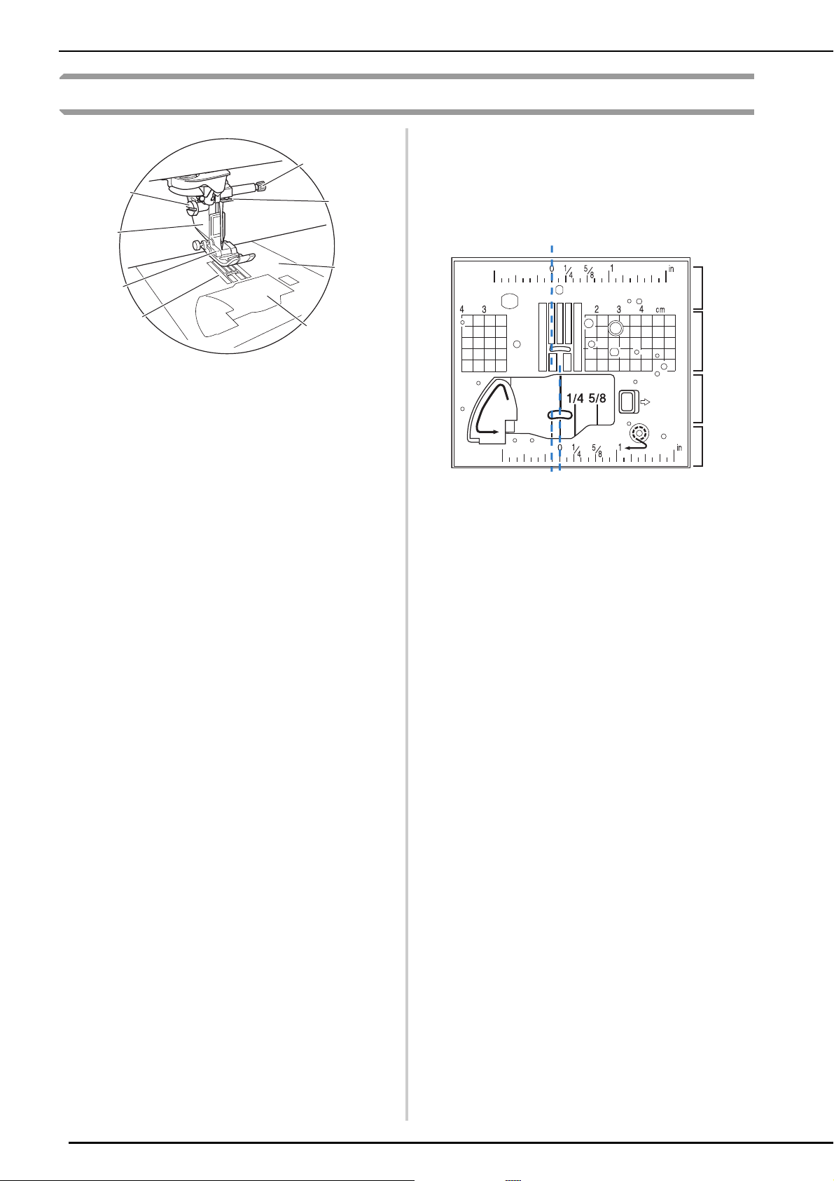
Measurements on the needle plate and the bobbin
cover (with mark)
The measurements on the bobbin cover and
needle plate are references for stitch patterns with
a left or middle (center) needle position.
b
c
d
e
f
b
a For stitches with a middle (center) needle position
b For stitches with a left needle position
c Left needle position on the needle plate <inch>
d Left needle position on the needle plate <cm>
e Middle (center) needle position on the bobbin cover
(with mark) <inch>
f Middle (center) needle position on the needle plate
<inch>
14
Page 17
NAMES OF MACHINE PARTS AND THEIR FUNCTIONS
CAUTION
a
b
c
d
e
CAUTION
abc
d
e
fg
h
Embroidery Unit
a Carriage
The carriage moves the embroidery frame automatically when
embroidering.
b Release lever (located under the embroidery unit)
Press the release lever to remove the embroidery unit.
c Embroidery frame holder
Insert the embroidery frame into the embroidery frame holder
to hold the frame in place.
d Frame-securing lever
Press the frame-securing lever down to secure the embroidery
frame.
e Embroidery unit connection
Insert the embroidery unit connection into the connection port
when attaching the embroidery unit.
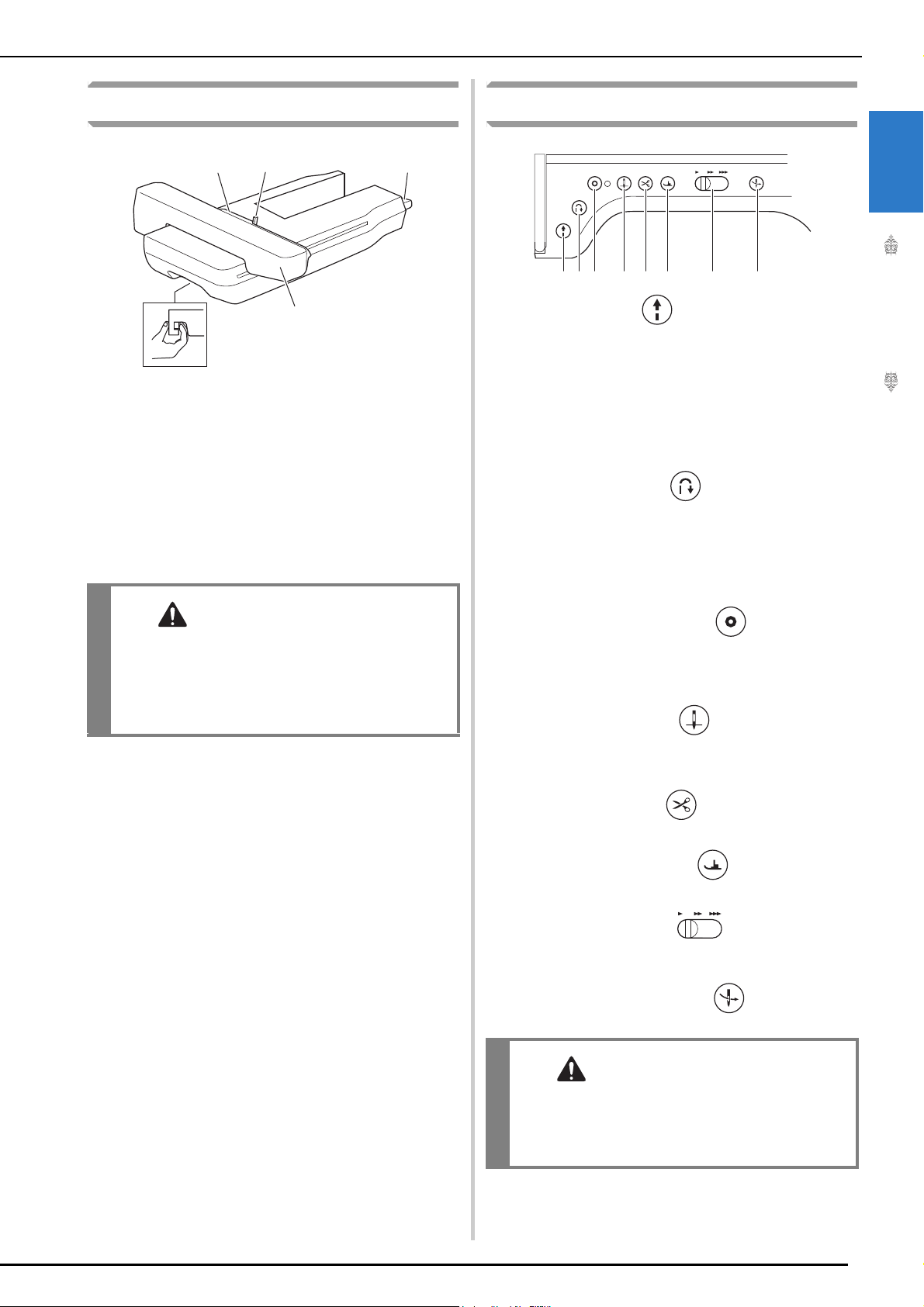
Operation Buttons
a “Start/Stop” button
Press this button and the machine will sew a few stitches at a
slow speed and then begin sewing at the speed set by the
sewing speed controller. Press the button again to stop the
machine. Hold the button in to sew at the machine’s slowest
speed. The button changes color according to the machine’s
operation mode.
Green: The machine is ready to sew or is sewing.
Red: The machine cannot sew.
b “Reverse Stitch” button
For straight, zigzag, and elastic zigzag stitch patterns that take
reverse stitches, the machine will sew reverse stitches at low
speed only while holding down the “Reverse Stitch” button.
The stitches are sewn in the opposite position.
For other stitches, use this button to sew reinforcement
stitches at the beginning and end of sewing. Press and hold
this button, and the machine sews 3 stitches in the same spot
and stops automatically. (page 79)
1
Getting Ready
• Before inserting or removing the embroidery
unit, turn the main power to off.
• After the embroidery frame is set in the frame
holder, be sure the frame-securing lever is
correctly lowered.
c “Reinforcement Stitch” button
Use this button to sew a single stitch repeatedly and tie-off.
For character/decorative stitches, press this button to end with
a full stitch instead of at a mid-point. The LED light beside this
button lights up while the machine is sewing a full motif, and
automatically turns off when the sewing is stopped. (page 79)
d “Needle Position” button
Use this button when changing sewing direction or for detailed
sewing in small areas. Press this button to raise or lower the
needle position. With this button, you can lower and raise the
needle to sew a single stitch.
e “Thread Cutter” button
Press this button after sewing to automatically trim the excess
thread.
f “Presser Foot Lifter” button
Press this button to lower the presser foot and apply pressure
to the fabric. Press this button again to raise the presser foot.
g Sewing Speed controller
Use this controller to adjust the sewing speed. Move the slide
to the left to sew at slower speeds. Move the slide to the right
to sew at higher speeds.
h “Automatic Threading” button
Use this button to automatically thread the needle.
• Do not press the thread cutter button after the
threads have been cut. The needle may break
and threads may become tangled, or damage
to the machine may occur.
15
Page 18

NAMES OF MACHINE PARTS AND THEIR FUNCTIONS
a
b
Using the Flat Bed Attachment
Pull the top of the flat bed attachment to open the
accessory compartment.
Using the Accessory Case
■ Opening the Accessory Case
Slide the latches on the front of the accessory case
outward to open it.
■ Using the Accessory Trays
Three presser foot storage trays are stored in the
included accessory case.
For your convenience, a presser foot storage tray
can be stored in the accessory compartment of the
flat bed attachment.
a Latches
a
a Presser foot storage space of the flat bed
attachment
b Presser foot storage trays
16
Page 19

Storing Bobbin Clips
Memo
Bobbin clips can be stored inside of the accessory
case cover.
• Placing bobbin clips on bobbins helps
prevent the thread from unwinding from the
bobbin. In addition, snapping bobbin clips
together allows the bobbins to be
conveniently stored and prevents them from
rolling around if they are dropped.
NAMES OF MACHINE PARTS AND THEIR FUNCTIONS
1
Getting Ready
17
Page 20
NAMES OF MACHINE PARTS AND THEIR FUNCTIONS
J
N
G
I
R
M
O
O
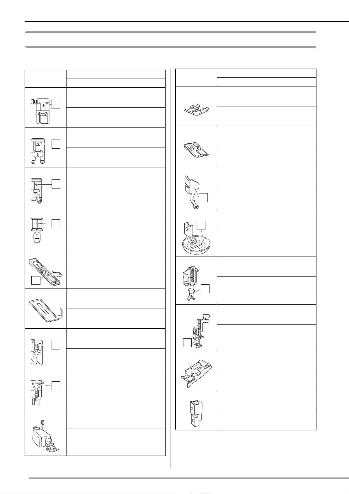
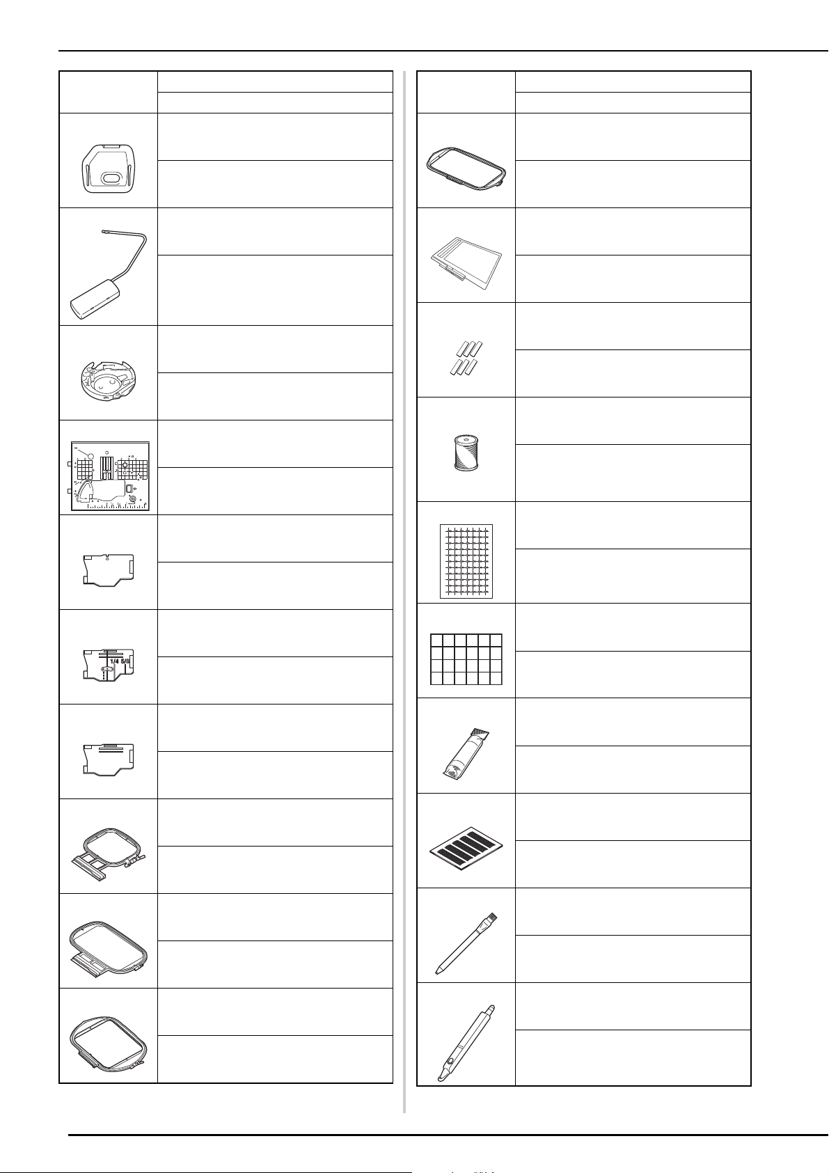
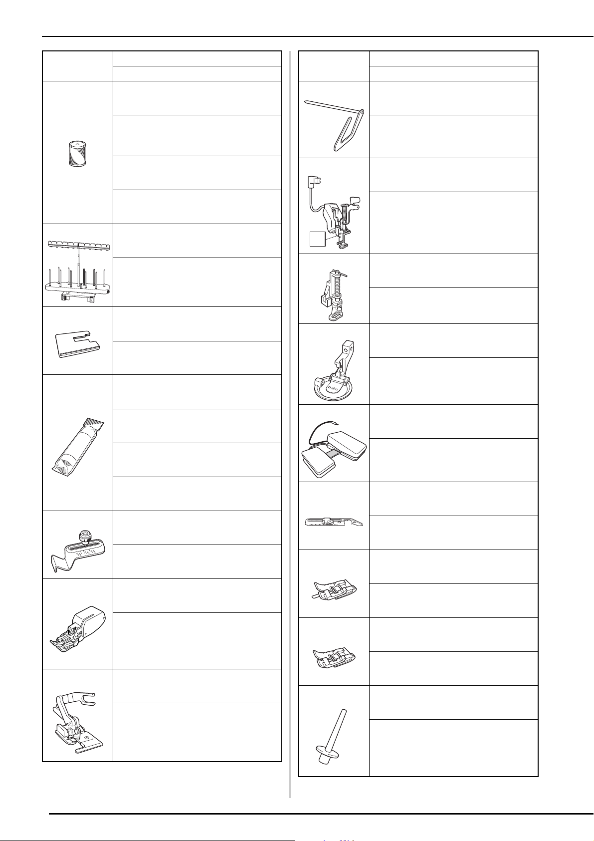
Included Accessories
After opening the box, check that the following accessories are included. If any item is missing or
damaged, contact your authorized Brother dealer.
Part Name
Part Code
1.
Zigzag foot “J” (on machine)
10.
Regular dual feed foot
Part Name
Part Code
XF3022-001
2.
Monogramming foot “N”
X53840-351
3.
Overcasting foot “G”
XC3098-051
4.
Zipper foot “I”
11.
12.
13.
XF4419-001
Straight stitch foot
SA167 (Americas)
F042: XC1973-052 (other area)
Free motion quilting foot “C”
XF4737-001
C
Free motion echo quilting foot “E”
E
X59370-051
5.
Buttonhole foot “A+”
A+
6.
XH2665-001
Buttonhole foot stabilizer
XH1726-001
14.
15.
E
XE0766-001
Free motion open toe quilting foot “O”
XF4873-001
Embroidery foot “W”
18
7.
Blind stitch foot “R”
XF4012-001
W
X56409-051
8.
Button fitting foot “M”
130489-001
9.
Dual feed foot
SA196 (Americas)
DF1: XF4166-001 (Europe)
DF1AP: XF6843-001 (other area)
16.
1/4 quilting foot with guide
SA185 (Americas)
F057: XC7416-252 / 115C05E0005 (Europe)
F057: 115C05E7005 (other area)
17.
Adapter
SA131 (Americas)
F010N: XF3613001 / 115Z05E0004 (Europe)
F010AP: 115Z05E7004 (other area)
Page 21

NAMES OF MACHINE PARTS AND THEIR FUNCTIONS
Part Name
Part Code
18.
Screw (small)
XA4813-051
19. Needle set
20.
21. Ball point needle set
22.
75/11 2 needles
90/14 2 needles
90/14 2 needles: Ball point needle (gold
colored)
XE4962-001
Twin needle
2.0/11 needle
XE4963-001
75/11 2 needles:
Ball point needle for embroidery
HAX130EBBR
XD0705-151
Bobbin × 10 (One is on machine.)
28.
29.
30.
31.
32.
Part Name
Part Code
Screwdriver (large)
XC4237-021
Multi-purpose screwdriver
SAMDRIVER1 (U.S.A) / SAMDRIVER1C
(Canada)
MDRIVER1: XG1298-001 / 115Z05E0003
(Europe)
MDRIVER1AP: 115Z05E7003 (other area)
Spool cap (small)
130013-154
Spool cap (medium) × 2 (One is on machine.)
X55260-153
Spool cap (large)
1
Getting Ready
23.
24.
25.
26.
27.
SA156 (Americas)
SFB: XA5539-151 / 115J05E0001 (Europe)
SFB: 115J05E7001 (other area)
Seam ripper
XF4967-001
Scissors
XF2052-001
Cleaning brush
X59476-051
Eyelet punch
XZ5051-001
Screwdriver (small)
130012-054
33.
Thread spool insert (mini king thread spool)
XA5752-121
34.
Spool stand
XH1606-001
Refer to “Using the Spool Stand” on page 24.
35.
Bobbin clip × 10
XE3060-001
36.
Spool felt (on machine)
X57045-051
37.
Spool net × 2
X55468-051
XA5523-050
19
Page 22
NAMES OF MACHINE PARTS AND THEIR FUNCTIONS
38.
39.
40.
41.
42.
Part Name
Part Code
Embroidery needle plate cover
XE4708-001
Knee lifter
SA599 (Americas)
KL1: XG6723-001 /115Z05E000C (Europe)
KL1: XE5902-001 / 115Z05E700C (other area)
Alternate bobbin case (no color on the screw)
XC8167-651
Straight stitch needle plate
XH1569-001
Cord guide bobbin cover (with single hole)
48.
49.
50.
51.
52.
Part Name
Part Code
Embroidery frame (LL) H 408 mm × W 272 mm
(H 16 inches × W 10-5/8 inches)
XH1466-001
Scanning frame
XF9321-001
Magnet × 6
XF9325-001
Embroidery bobbin thread
SA-EBT (Americas)
EBT-CEN: X81164-001 / 115G05E0001
(Europe)
EBT-CEN: 115G05E7001 (other area)
Embroidery positioning sticker sheets × 2
43.
44.
45.
46.
47.
XE0085-101
Bobbin cover (with mark)
XH3126-001
Bobbin cover (on machine)
XF9666-101
Embroidery frame (medium) H 100 mm × W
100 mm (H 4 inches × W 4 inches)
SA438 (Americas)
EF74: XC8480-152 / 115D05E0005 (Europe)
EF74: 115D05E7005 (other area)
Embroidery frame (large) H 180 mm × W 130
mm (H 7 inches × W 5 inches)
SA439 (Americas)
EF75: XC8481-152 / 115D05E0001 (Europe)
EF75: 115D05E7001 (other area)
Embroidery frame (quilt) H 240 mm × W 240
mm (H 9-1/2 inches × W 9-1/2 inches)
SAEPS2 (U.S.A.) / SAEPS2C (Canada)
EPS2: XG6749-001 / 115Z05E000E (Europe)
EPS2: 115Z05E700E (other area)
53.
White calibration stickers (solid)
XE7916-001
54.
Stabilizer material
SA519 (Americas)
BM3: XG6683-001 / 115Z05E0007 (Europe)
BM3: 115Z05E7007 (other area)
55.
Grid sheet set
SA507 (Americas)
GS3: X81277-151 (other area)
56.
Chalk pencil
XE8568-001
57.
Dual purpose stylus
20
XG5558-001
XH1791-001
XH1807-001 (Europe)
Page 23
58.
Memo
59.
Part Name
Part Code
Dual purpose stylus holder
XH1805-001
Accessory case
NAMES OF MACHINE PARTS AND THEIR FUNCTIONS
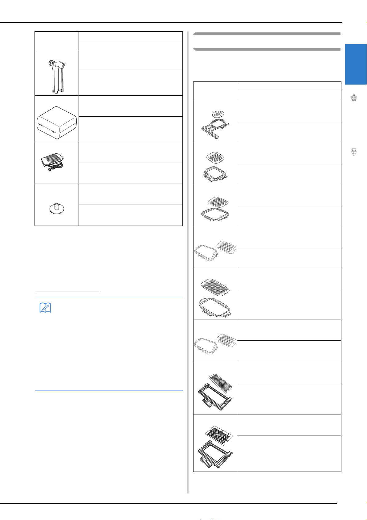
Options
The following are available as optional accessories
to be purchased separately from your authorized
Brother dealer.
Part Name
Part Code
1.
Embroidery frame set (small) H 20 mm × W 60
mm (H 1 inch × W 2-1/2 inches)
1
Getting Ready
XH1836-001
60.
Foot controller
XC8816-051
61.
Bobbin center pin and instruction sheet
XF5048-001
Following documents can be downloaded at
Brother Solutions Center:
• Operation Manual (Sewing)
• Operation Manual (Embroidery)
• Embroidery Design Guide
• DISNEY DESIGN GUIDE
http://s.brother/cpdab/
• (For U.S.A. only)
Foot controller: Model T
This foot controller can be used on the
machine with product code 882-W30. The
product code is mentioned on the machine
rating plate.
• Always use accessories recommended for
this machine.
• The screw for the presser foot holder is
available through your authorized Brother
dealer (Part code XA4813-051).
SA437 (Americas)
EF73: XG6663-001 (Europe)
EF73: XC8479-152 (other area)
2.
3.
4.
5.
6.
7.
8.
Embroidery frame set (square) H 150 mm × W
150 mm (H 6 inches × W 6 inches)
SA448 (U.S.A.) SA448C (Canada)
SEF150: XG6761-001 (Europe)
SEF150: 115D05E000E (other area)
Embroidery frame set (quilt) H 200 mm × W
200 mm (H 8 inches × W 8 inches)
SA446 (U.S.A.) SA446C (Canada)
EF91: XG6715-001 (Europe)
EF91: XE5068-101 (other area)
Embroidery frame set (extra large) H 300 mm ×
W 200 mm (H 12 inches × W 8 inches)
SA447 (Americas)
EF92: XG6717-001 (Europe)
EF92: XE5071-001 (other area)
Embroidery frame set (extra large) H 260 mm ×
W 160 mm (H 10-1/4 inches × W 6-1/4 inches)
SA441 (Americas)
EF81: XG6673-001 (Europe)
EF81: XC9763-152 (other area)
Embroidery frame set (super large) H 360 mm
× W 240 mm (H 14 inches × W 9-1/2 inches)
XF9309-001
Border embroidery frame H 300 mm × W 100
mm (H 12 inches × W 4 inches)
SABF6200D1 (U.S.A.) SABF6200D1C
(Canada)
BF3: XG6763-001 (Europe)
BF3: XF4170-001/115D05E000N (other area)
Border embroidery frame set H 180 mm × W
100 mm (H 7 inches × W 4 inches)
SABF6000D (U.S.A.) SABF6000DC (Canada)
BF2: XG6079-001 (Europe)
BF2: XE5059-001 (other area)
21
Page 24
NAMES OF MACHINE PARTS AND THEIR FUNCTIONS
9.
10.
11.
12.
Part Name
Part Code
Embroidery bobbin thread (white)
SA-EBT (Americas)
EBT-CEN: X81164-001 / 115G05E0001
(Europe)
EBT-CEN: 115G05E7001 (other area)
Embroidery bobbin thread (black)
SA-EBT999 (Americas)
EBT-CEBN: XG6643-001 (Europe)
EBT-CEBN: XC5520-001 (other area)
10 spool stand
SA561 (U.S.A.) SA561C (Canada)
TS5: XG6765-001 (Europe)
TS5: XF4175-001 (other area)
Wide table
SAWTXP1 (U.S.A.)
SAWTXP1C (Canada)
WT16AP: 115K05E700J (other area)
Stabilizer material
Part Name
Part Code
16.
Quilting guide
SA132 (Americas)
F016N: XC2215-052 (Europe)
F016N: 115Z05E7001 (other area)
17.
Embroidery foot “W+” with LED pointer
SA197 (U.S.A.) SA197C (Canada)
FLED1: XF4168-001 (Europe)
FLED1AP: 115C05E700W (other area)
W+
18.
Free-motion quilting foot
SA129 (Americas)
F005N: XC1948-052 (Europe)
F005N: 115C05E7002 (other area)
19.
Couching foot
SA199V (U.S.A.) SA199VC (Canada)
F073: XF8185-001 (Europe)
F073AP: XF8188-001 (other area)
13.
14.
15.
SA519 (Americas)
BM3: XG6683-001 / 115Z05E0007 (Europe)
BM3: 115Z05E7007 (other area)
Water soluble stabilizer
SA520 (Americas)
BM5: XG6681-001 (Europe)
BM5: XE0615-001 (other area)
Seam guide
SA538 (Americas)
SG1: XC8483-052 (Europe)
SG1: 115Z05E7002 (other area)
Walking foot
SA140 (Americas)
F033N: XG6623-001 (Europe)
F033N: 115C05E7015 (other area)
Side cutter foot
20.
Multi-Function Foot controller
SAMFFC (U.S.A.) SAMFFCC (Canada)
MFFC1: XG6777-001 (Europe)
MFFC1OC: XF4471-001 (Australia)
21.
Circular attachment
SACIRC1 (Americas) SACIRC1C (Canada)
CCIRC1: XG6705-001 (Europe)
CIRC1: 115Y05E7003 (other area)
22.
Stitch in the ditch foot
SA191 (Americas)
F065: XF2339-001 (Europe)
F065: 115C05E700C (other area)
23.
Edge joining foot
SA184 (Americas)
F056: XC6441-352 (Europe)
F056: 115C05E700K (other area)
24.
Vertical spool pin
22
SA177 (Americas)
F054: XC3879-152 (Europe)
F054: 115C05E7008 (other area)
XC8619-052
Page 25

NAMES OF MACHINE PARTS AND THEIR FUNCTIONS
I+
Memo
Note
25.
26.
27.
28.
29.
Part Name
Part Code
Embroidery positioning sticker sheets × 8
SAEPS2 (U.S.A.) / SAEPS2C (Canada)
EPS2: XG6749-001 / 115Z05E000E (Europe)
EPS2: 115Z05E700E (other area)
Free motion guide grip
SAFMGRIP (Americas)
FMG2: XF6266-001 (Europe)
FMG2AP: XF6267-001 (other area)
USB mouse
XE5334-101
Vertical stitch alignment foot “V”
V
SA189 (Americas)
F063: XG6721-001 (Europe)
F063: XE5224-001 (other area)
Open toe for dual feed foot
35.
36.
37.
38.
39.
Part Name
Part Code
Bi-level Foot (Right)
SA103 (U.S.A.) SA103C (Canada)
F081: 115C05E002F (Europe)
F081AP: 115C05E702F (other area)
Bi-level Foot (Left)
SA104 (U.S.A.) SA104C (Canada)
F082: 115C05E002G (Europe)
F082AP: 115C05E702G (other area)
Concealed Zipper Foot “K”
K
SA102 (U.S.A.) SA102C (Canada)
F080: 115C05E002E (Europe)
F080AP: 115C05E702E (other area)
Embroidery frame sheet (medium) H 100 mm ×
W 100 mm (H 4 inches × W 4 inches)
XC8357-051
Embroidery frame sheet (large) H 180 mm × W
130 mm (H 7 inches × W 5 inches)
1
Getting Ready
30.
31.
32.
33.
34.
SA195 (Americas)
F070: XG6773-001 (Europe)
F070: XF6096-001 (other area)
Stitch in the Ditch Dual Feed Foot
SA204 (U.S.A.) SA204C (Canada)
F075: XG3155-001 (Europe)
F075AP: 115C05E700Y (other area)
1/4 inch Guide Dual Feed Foot
SA205 (U.S.A.) SA205C (Canada)
F076: XG4868-001 (Europe)
F076AP: 115C05E701D (other area)
Dual Feed Quilting Guide
SA206 (U.S.A.) SA206C (Canada)
F077: XG4879-001 (Europe)
F077AP: 115Z05E7008 (other area)
Ruffler foot
SA143 (Americas)
F051: XA9093-052 (Europe)
F051: 115C05E700L (other area)
Narrow Zipper Foot “I+”
SA208 (U.S.A.) SA208C (Canada)
F079: 115C05E002D (Europe)
F079AP: 115C05E702D (other area)
XC8359-051
40.
41.
42.
Embroidery frame sheet (quilt) H 240 mm × W
240 mm (H 9-1/2 inches × W 9-1/2 inches)
XG5566-001
Embroidery frame sheet (LL) H 408 mm × W
272 mm (H 16 inches × W 10-5/8 inches)
XH1825-001
Bobbin Work Kit
SABWRK1 (U.S.A.) SABWRK1C (Canada)
BWRK1: XG6745-001 (Europe)
BWRK1: XE9099-001 (other area)
• All specifications are correct at the time of
printing. Please be aware that some
specifications may change without notice.
• Visit your nearest authorized Brother dealer
for a complete listing of optional
accessories for your machine.
23
Page 26

NAMES OF MACHINE PARTS AND THEIR FUNCTIONS
Note
CAUTION
Using the Multi-purpose
Screwdriver
Since the screwdriver can be changed to three
different positions, it can be extremely useful for
the various machine preparations. With this
machine, position “1” and position “3” are used.
■ Position “1”
You can install/remove the presser foot holder,
needle clamp screw.
Using the Spool Stand
The included spool stand is useful when using
thread spools with a large diameter (cross-wound
thread). The spool stand can hold two spools of
thread.
123
456
No. Part Name Part Code
1 Spool stand XH1606-001
2 Spool cap (XL) × 2 XE0779-001
3 Spool holder × 2 XA0679-050
4 Spool cap base × 2 XE0780-001
5 Spool felt × 2 XC7134-051
6 Ring × 4 026030-136
* No.2 to No.6 are included in a plastic bag.
■ Position “3”
The multi-purpose screwdriver can be positioned
over the screw on the embroidery frame to tighten
the screw after hooping the fabric or when removing
the fabric.
• When rotating the multi-purpose
screwdriver, do not forcefully rotate it in the
direction that it does not rotate; otherwise, it
may break.
• Do not lift the handle of the machine while the
spool stand is installed.
• Do not push or pull the telescopic thread
guide or spool pins with extreme force,
otherwise damage may result.
• Do not place any object other than spools of
thread on the spool support.
• Do not try to wind thread on the bobbin while
sewing using the spool stand.
■ Warning label
This product contains magnets.
a Be careful not to pinch your fingers or any objects
between the spool stand and the upper cover of
the machine.
b Be sure to keep the magnets away from precision
electronics, computer disks, credit cards with a
magnetic stripe, etc.
c Do not use the spool stand if you have a
pacemaker.
24
Page 27
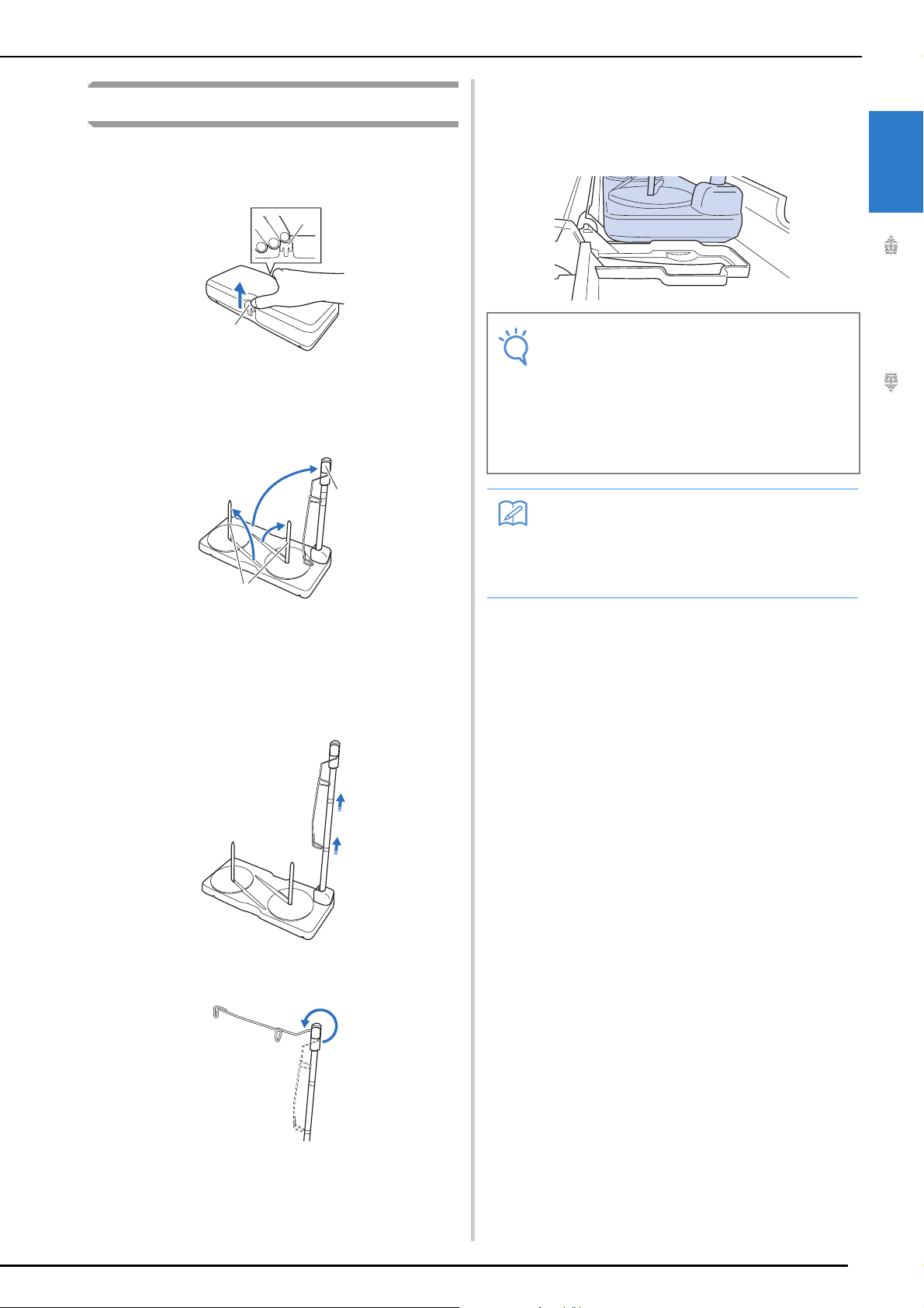
Assembling the Spool Stand
a
a
b
a
Note
Memo
Hold in the tabs on the spool stand and
a
remove the lid.
a Tabs
Raise the telescopic thread guide shaft and
b
the two spool pins.
NAMES OF MACHINE PARTS AND THEIR FUNCTIONS
Open the upper cover of the machine, and
e
then place the spool stand on the upper
cover with the notches in the spool stand
aligned with the tabs on the upper cover.
• Make sure that the spool stand is firmly
secured. Otherwise, the spool stand may
fall during sewing.
• Do not place any object weighing 1 kg or
more on the top cover. The weight of the
spool stand with its lid removed is about
280 g.
1
Getting Ready
a Spool pins
b Telescopic thread guide shaft
Fully extend the telescopic thread guide
c
shaft until the two internal stoppers snap
into place.
Turn the thread guide counterclockwise.
d
• For details on winding the bobbin using the
spool stand, refer to page 56.
• For details on upper threading using the
spool stand, refer to page 66.
25
Page 28
TURNING THE MACHINE ON/OFF
WARNING
CAUTION
TURNING THE MACHINE ON/OFF
• Use only regular household electricity for the power source. Using other power sources may result in fire,
electric shock, or damage to the machine.
• Make sure that the plugs on the power cord are firmly inserted into the electrical outlet and the power
cord receptacle on the machine. Otherwise, a fire or electric shock may result.
• Do not insert the plug on the power cord into an electrical outlet that is in poor condition.
• Turn the main power to OFF and remove the plug in the following circumstances:
When you are away from the machine
After using the machine
When the power fails during use
When the machine does not operate correctly due to a bad connection or a disconnection
During electrical storms
• Use only the power cord included with this machine.
• Do not use extension cords or multi-plug adapters with many other appliances plugged in to them. Fire or
electric shock may result.
• Do not touch the plug with wet hands. Electric shock may result.
• When unplugging the machine, always turn the main power to OFF first. Always grasp the plug to remove
it from the outlet. Pulling on the cord may damage the cord, or lead to fire or electric shock.
• Do not allow the power cord to be cut, damaged, modified, forcefully bent, pulled, twisted, or bundled.
Do not place heavy objects on the cord. Do not subject the cord to heat. These things may damage the
cord, or cause fire or electric shock. If the cord or plug is damaged, take the machine to your authorized
Brother dealer for repairs before continuing use.
• Unplug the power cord if the machine is not to be used for a long period of time. Otherwise, a fire may
result.
• When leaving the machine unattended, either the main switch of the machine should be turned to OFF or
the plug must be removed from the socket-outlet.
• When servicing the machine or when removing covers, the machine must be unplugged.
•For U.S.A only
This appliance has a polarized plug (one blade wider than the other). To reduce the risk of electrical
shock, this plug is intended to fit in a polarized outlet only one way.
If the plug does not fit fully in the outlet, reverse the plug. If it still does not fit, contact a qualified
electrician to install the proper outlet. Do not modify the plug in any way.
26
Page 29
TURNING THE MACHINE ON/OFF
Memo
Memo
Note
b
a
c
d
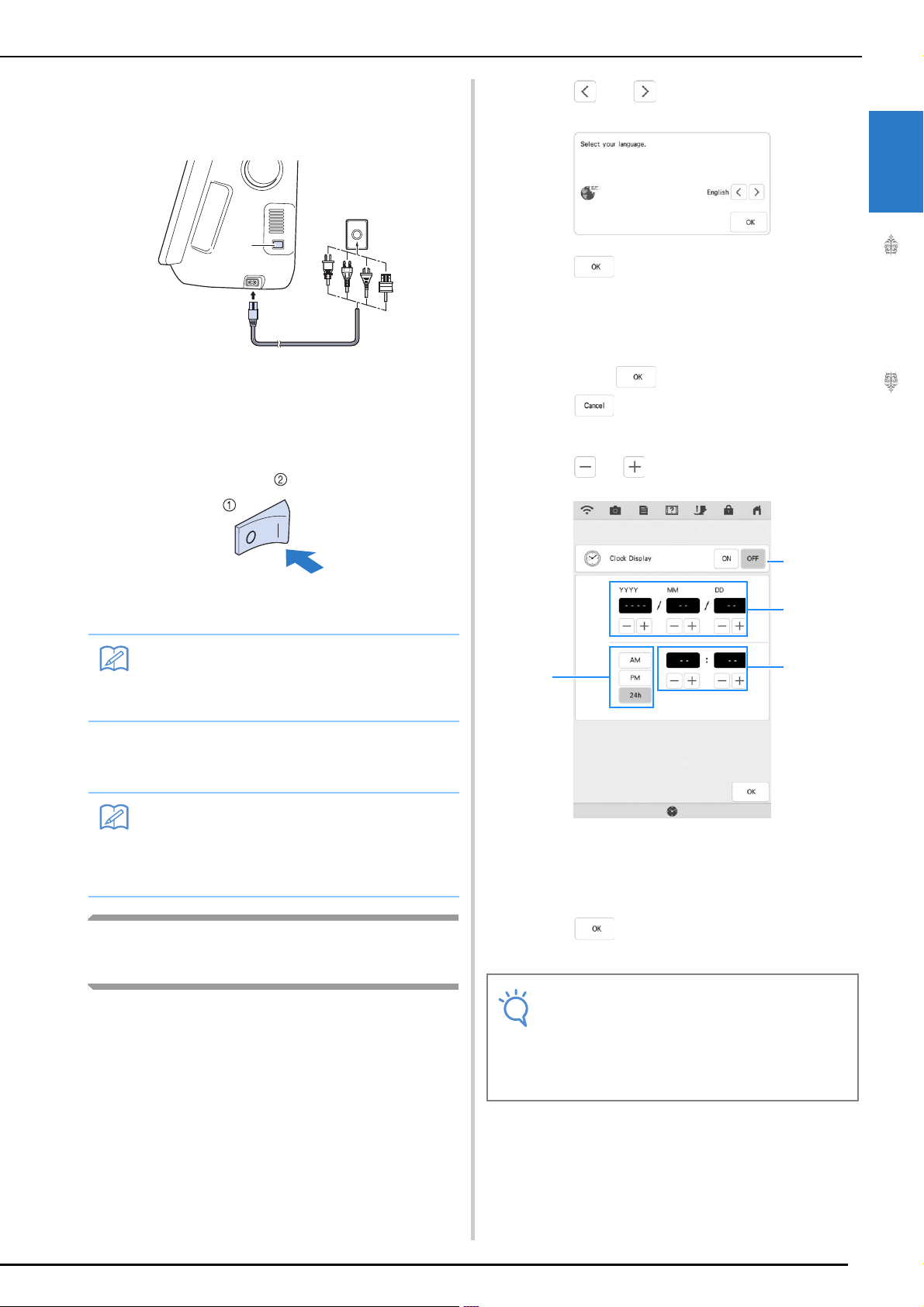
Insert the power supply cord into the power
a
cord receptacle, then insert the plug into a
wall outlet.
a
b
a Main power switch
b Power supply cord
Turn the main power switch to “I” to turn
b
on the machine.
Press and to set your local language.
a
Press .
b
The message screen, confirming if you want
c
to set time/date, appears. To set the time/
date, press ; to cancel the setting,
press .
The screen to set time/date appears.
Press or to set time date.
d
1
Getting Ready
a OFF
b ON
• When the machine is turned on, the needle
and the feed dogs will make sound when
they move; this is not a malfunction.
Turn the main power switch to “O” to turn
c
off the machine.
• If the machine is turned off in the middle of
sewing in the “Sewing” function, the
operation will not be continued after turning
the power on again.
Setting Your Machine for the First
Time
When you first turn on the machine, set the
language and time/date to your language and local
time/date. Follow the procedure below when the
settings screen appears automatically.
a Press to display the time on the screen.
b Set the year (YYYY), month (MM) and date (DD).
c Select whether 24h or 12h setting to display.
d Set the current time.
Press to start using your machine.
e
The clock starts from 0 second of the time you set.
• The time/date you set may be cleared, if
you don't turn on the machine for an
extended period of time.
• Time setting is also available by pressing
clock button/time on the LCD screen.
27
Page 30
LCD SCREEN
Note
Memo
b
c
a
l
e f g h i jdk
LCD SCREEN
When the machine is turned on, the opening
movie is played. Touch anywhere on the screen
for the home page screen to be displayed. Touch
the LCD screen or a key with your finger or the
included dual purpose stylus to select a machine
function.
• When the straight stitch needle plate is on
the machine, the needle will automatically
move to the middle position.
• Only touch the screen with your finger or the
included dual purpose stylus. Do not use a
sharp pencil, screwdriver, or other hard or
sharp object. It is not necessary to press
hard on the screen. Pressing too hard or
using a sharp object may damage the
screen.
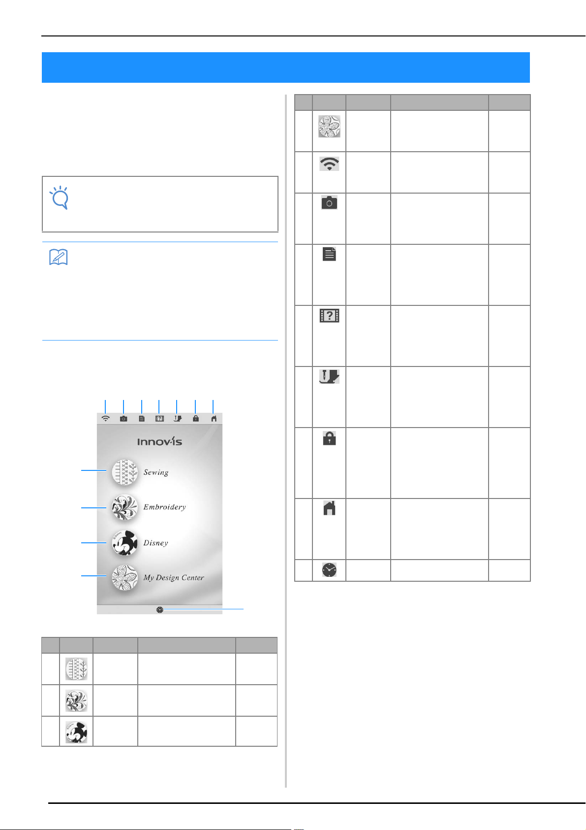
■ Home Page Screen
No. Display Key Name Explanation Page
d My Design
Center key
e Wireless
LAN key
f Camera
view key
g Machine
setting
screen key
h Machine
help key
i Presser
foot/
Needle
exchange
key
j Screen
lock key
k Home
page
screen key
l Time/Date
key
Press this key to start
creating your custom
design embroidery
patterns.
Check the machine’s
signal strength. Press this
key to specify the wireless
settings.
Press this key to check the
needle location as it is
shown on the screen
through the built-in
camera.
Press this key to change
the needle stop position,
adjust the stitch patterns
and embroidery patterns
or screen, and change
other machine settings.
Press this key to see
explanations on how to
use the machine. You can
see the tutorial videos and
also the MP4 movie files
that you have.
Press this key before
changing the needle, the
presser foot, etc. This key
locks all key and button
functions to prevent
operation of the machine.
Press this key to lock the
screen. When the screen
is locked, can still sew, but
cannot change any of the
screen functions. Press
this key again to unlock
the settings.
Press this key anytime it is
displayed to return to the
home page screen and
select a different category
- “Sewing”, “Embroidery”
or “My Design Center”.
Press this key to set the
clock to your local time.
–
46
92
29
39
58, 72
158
–
27
No. Display Key Name Explanation Page
a Sewing key Press this key to sew utility
b Embroidery
key
c Disney key Press this key to sew
stitches or character/
decorative stitch patterns.
Attach the embroidery unit
and press this key to
embroider patterns.
Disney stitch patterns.
28
102, 158
–
–
Page 31

LCD SCREEN
Memo
a
b
c
d
e
f
g
h
i
j
k
Using the Machine Setting Mode Key
Press to change the default machine settings (needle stop position, embroidery speed, opening
display, etc.). To display the different settings screens, press for “Sewing settings”, for “General
settings”, for “Embroidery settings” or for “Wireless LAN settings”.
1
• Press or to display a different settings screen.
Sewing Settings
■ Page 1
a Select whether to use the sewing speed controller
to determine the zigzag width (page 125).
b Make adjustments to character or decorative
stitch patterns (page 164).
c Adjust the presser foot height. Select the height of
the presser foot when the presser foot is raised.
d Adjust the presser foot pressure. The higher the
number, the greater the pressure will be. Set the
pressure at “3” for normal sewing.
e When set to “ON”, the thickness of the fabric is
automatically detected by an internal sensor while
sewing. This enables the fabric to be fed smoothly
(pages 83 and 91).
Getting Ready
■ Page 2
f Select whether “1-01 Straight stitch (Left)” or “1-
03 Straight stitch (Middle)” is the utility stitch that
is automatically selected when the machine is
turned on.
g Change the height of the presser foot when
sewing is stopped when the pivot setting is
selected (page 89). Adjust the presser foot to one
of the four heights.
h Change the height of the presser foot when the
machine is set to free motion sewing mode
(page 126).
i Adjust the amount of fabric feeding of the dual
feed foot (page 76).
j Pressing the “Start/Stop” button or depressing the
foot controller automatically lowers the presser
foot (if it is raised) before starting sewing.
k Pressing the “Thread Cutter” button automatically
lowers the presser foot before cutting the thread.
The presser foot will be raised after the thread is
cut.
29
Page 32

LCD SCREEN
n
l
m
a
d
f
b
c
e
■ Page 3
l Select whether utility stitches ( ) or quilting
stitches ( ) are displayed first in the stitch
selection screen.
m When set to “ON”, reinforcement stitches are
sewn at the beginning and/or end of sewing for a
reinforcement stitch pattern, even when the
“Reverse Stitch” button is pressed (page 79).
n You can activate this setting after connecting the
multi-function foot controller (optional). (These
settings are not operable unless the multi-function
foot controller is attached to the machine.)
(page 34)
General Settings
■ Page 4
a Change the display language.
b Change the brightness of the needle area and
work area lights.
c If the screen is not very clear in certain
environments, you can adjust the brightness of the
screen.
d Turn both the upper and bobbin thread sensor
“ON” or “OFF”. If it is turned “OFF”, the machine
can be used without thread.
e Change the speaker volume. Increase the number
for louder volume, decrease for softer volume.
f Select the operation of the “Needle Position -
Stitch Placement” button from the following two
sequences. (page 92)
30
Page 33

LCD SCREEN
i
h
j
k
g
p
o
n
l
m
q
t
r
s
■ Page 5
g Select whether to display the opening screen
video when the machine is turned on.
h Select to save the machine power by setting the
“Eco Mode” or the “Shutoff Support Mode”
(page 35).
i Select the length of time until the screen saver
appears.
j Change the image of the screen saver (page 36).
k Change the shape of the pointer when a USB
mouse is used. The setting remains selected even
after the machine is turned off.
■ Page 7
1
Getting Ready
q Display the service count which is a reminder to
take your machine in for regular servicing.
(Contact your authorized Brother dealer for
details.)
r Display the total number of stitches sewn on this
machine.
s The “No.” is the internal machine number for the
machine.
t Display the program version.
■ Page 6
l Select the brightness of the projector.
m Select whether to show background color when
using projector function.
n Select whether to display outline of the pattern.
o Select the color of the pointer.
p The camera needle drop point can be specified.
(page 37)
31
Page 34

LCD SCREEN
a
d
e
f
b
c
j
k
g
h
l
i
m
p
q
o
n
Embroidery Settings
For details on embroidering settings, refer to the
Operation Manual (Embroidery).
■ Page 8
a Select from among 12 embroidery frame displays.
b Change the center point marker or grid lines.
c Adjust the maximum embroidery speed setting.
d Adjust the upper thread tension for embroidering.
e Select the height of the embroidery foot during
embroidering.
f Adjust the needle position for embroidering.
■ Page 9
g Change the display units (mm/inch).
h Change the thread color display on the
“Embroidery” screen; thread number, color name.
i Select the thread brand used to display a pattern
when it is opened.
j Change the color of the background for the
embroidery display area.
k Change the color of the background for the
thumbnail area.
l Press to specify the size of pattern thumbnails.
m Adjust the distance between the pattern and the
basting stitching.
■ Page 10
32
n Select the quality for displaying the fabric in the
screen.
o Erase the scanned image.
p Set to “ON” when positioning the pattern on the
thick fabric using the built-in camera.
q Adjust the position and brightness of the
embroidery foot “W+” with LED pointer (sold
separately). (These settings are not available
unless embroidery foot “W+” with LED pointer is
installed on the machine.)
Page 35

Wireless LAN settings
c
d
b
a
e
f
g
h
a
b
■ Page 11
Press .
b
The settings screen appears. Select the settings
screen page that you want to save the screen image
of.
Press .
c
The image file will be saved to the USB media.
LCD SCREEN
1
Getting Ready
a Enable/disable the wireless LAN function.
b Display the connected SSID.
c Set the machine to connect wireless LAN function.
d Display the machine name of wireless LAN
function.
e Press to change the machine name of
wireless LAN function.
f Check the wireless LAN status.
g Display other menus.
h Press to reset network operations.
Setting Functions
■ Saving a Settings Screen Image to
USB Media
An image of the settings screen can be saved as
.PNG file.
Insert the USB media into the USB port on
a
the right side of the machine.
a USB media
b USB port
33
Page 36

LCD SCREEN
Memo
Note
■ Specifying the Multi-Function Foot
Controller (Sold Separately)
With the multi-function foot controller, various
machine operations in addition to starting/
stopping sewing, such as thread cutting and
reverse stitching, can be specified to be
performed.
Functions that can be specified
Controller Functions that can be specified
a Main foot controller Start/Stop
b Heel switch Select any of the following:
c Side pedal
* If you set the “Reverse Stitch” function on the heel
switch, machine operates the same as pressing the
“Reverse Button” on the machine.
* Reinforcement stitching may be applied depending
on the selected stitch pattern. For the details, refer to
“Automatic Reinforcement Stitching” on page 79.
• Thread Cutting
• Needle Position – Up/Down
• Single Stitch
• Reverse Stitch (Reinforcement
Stitch) *
• Presser Foot Up/Down
• No Setting
Press .
a
Display page 3 of the settings screen.
b
Select the functions to be performed by the
c
multi-function foot controller.
Press .
d
• If you set “Reverse Stitch” on the side
pedal, you can create a darning stitch effect
using zigzag stitches. With both feet, keep
pressing the main foot controller, and
repeat pressing and releasing the side pedal
to sew forward and reverse in turn. Machine
will reverse at the speed you press the main
foot controller.
Specifying the functions
The functions performed by the multi-function foot
controller can be specified in the settings screen.
• Before specifying the functions, connect the
multi-function foot controller to the
machine. The settings screen is activated
the first time that the machine detects the
multi-function foot controller.
• After the multi-function foot controller is
connected to the machine and the functions
are specified, the “Start/Stop” button
cannot be used. All buttons other than the
“Start/Stop” button can continue to be
used.
34
Page 37

■ Selecting the “Eco Mode” or
Note
LCD SCREEN
“Shutoff Support Mode”
You can save the machine power by setting the eco
mode or the shutoff support mode.
If you leave the machine without using for a
specified period of time, the machine enters in one
of these modes.
“Eco Mode”;
Machine will enter a sleep mode. Touch the screen
or press the “Start/Stop” button to continue sewing.
“Shutoff Support Mode”;
Machine will enter the lower power mode after set
period of time. Turn machine off and then back on
to restart sewing.
Condition Eco Mode Shutoff Support
Available time OFF, 10 - 120
(minute)
“Start/Stop” button Green flashing Green slow flashing
Suspended function Machine light,
Screen display
After recovering The machine starts
from the previous
operation.
Mode
OFF, 1 - 12 (hour)
All functions
You need to turn off
the machine.
• If you turn off the machine while the
machine is in the “Eco Mode” or the
“Shutoff Support Mode”, wait for about 5
seconds before turning on the machine
again.
1
Getting Ready
Press the “Start/Stop” button or touch the screen
display to recover from these modes.
Press .
a
The settings screen appears.
Press .
b
The General settings screen appears.
Display page 5 of the General settings
c
screen.
Press circled area to select the time until
d
entering the mode.
35
Page 38

LCD SCREEN
■ Changing the Screen Saver Image
Instead of the default image, you can select your
own personal images for the screen saver of your
machine.
Before changing the screen saver image, prepare the
image on your computer or USB media.
Compatible image files
Format
File size
File dimension
Number allowed
Press .
a
The settings screen appears.
Press .
b
The General settings screen appears.
Display page 5 of the General settings
c
screen.
.bmp, .jpg, .png
Max. 2 MB for each image
800 × 1280 pixels or less, (If the width is
more than 800 pixels, the image imported
will be reduced to a width of 800 pixels.)
5 or less
Press .
e
Connect the USB media that contains your
f
personal image to the USB port of the
machine.
* Refer to page 49 about USB connectivity.
Press .
d
Press to select the first image.
g
* The images will appear in a list in this screen. Select
the desired to specify the image.
* Press to delete the selected image.
36
Page 39

LCD SCREEN
Select the device that is connected.
h
A list of your personal images appear on the screen.
* Press to view the previous page.
Press a file name to select image and then
i
press .
■ Needle Calibration Using the Builtin Camera
Setting the camera needle position is essential
when you use camera or projector function. It is
not necessary to perform this operation each time,
but we recommend performing it when the needle
is changed. Use the white stickers (solid) included
with the machine.
Press .
a
The settings screen appears.
Press .
b
The General settings screen appears.
Display page 6 of the General settings
c
screen.
1
Getting Ready
The selected image is stored on your machine.
* Press to view the previous page.
Repeat the procedure from step g to select
j
the remaining images.
Press to return to the original screen.
k
Press .
d
Camera needle position setting screen appears.
Follow the on-screen instructions to
e
complete the procedure.
1. Press the needle position button to raise the
needle.
37
Page 40

LCD SCREEN
Note
2. After removing the needle and the presser
foot, affix white sticker on needle dropping
point area.
a White sticker
3. Insert the needle (standard size 75/11 or 90/
14).
• Use a new sticker. The camera needle
position cannot be set correctly if there is a
hole in sticker or if it is dirty. If you have no
new stickers, contact your nearest
authorized Brother dealer.
4. Press to initiate the calibration
process. For safety please make sure area
around needle is clear prior to pressing
.
Setting the needle drop point begins.
The operation is finished when “OK”
f
appears. If “NG” appears, affix a new white
sticker, and then press . If multiple
attempts to set the position are not
successful, contact your nearest authorized
Brother dealer.
* Press to memorize the calibration data.
* Press to back to original screen without
memorizing the calibration data.
Remove the sticker.
g
38
Page 41

LCD SCREEN
a
b
c
d
e
f
Using the Machine Help Key
Press to open the machine help screen. Six functions are available from the screen shown below.
1
Getting Ready
a Press this key to continue viewing the Operation Manual (PDF file) or watching the video that was stopped.
b Press this key to view the Operation Manual (PDF file).
c Press this key to see explanation for upper threading, winding the bobbin, changing the presser foot, preparing to
embroider a pattern, and how to use the machine (page 40).
d Press this key to select utility stitches when you are not sure which stitch to use or how to sew the stitch (page 41).
e Press this key to see an explanation of the selected stitch (page 44).
f Press this key to watch tutorial videos or MPEG-4 (MP4) files from USB media (page 42).
39
Page 42

LCD SCREEN
Using the Operation Guide Function
Press to open the screen shown below. Six categories are displayed at the top of the
screen. Press a key to see more information about that category.
displays information about the
main parts of the machine and their
functions. This is the first screen displayed
when you press .
displays information about
attaching the embroidery unit, preparing
fabric for embroidering, etc.
Some of the functions are described in the
movies. Watch these movies for a better
understanding of the functions.
displays information about the
operation buttons.
displays troubleshooting
information.
displays information about
threading the machine, changing presser
feet, etc. Some of the functions are described
in the movies. Watch these movies for a
better understanding of the functions.
displays information about
cleaning the machine, etc.
Some of the functions are described in the
movies. Watch these movies for a better
understanding of the functions.
40
Page 43

Example: Displaying information about upper
threading
LCD SCREEN
Using the Sewing Guide Function
Press .
a
Press .
b
Press .
c
The lower half of the screen will change.
The sewing guide function can be used to select
stitch patterns from the Utility Stitch screen.
Use this function when you are not sure which
stitch to use for your application, or to get advice
about sewing particular stitches. For example, if
you want to sew overcasting, but you do not know
which stitch to use or how to sew the stitch, you
can use this screen to get advice. We recommend
that beginners use this method to select stitches.
Enter Utility Stitch category from the home
a
page.
Press .
b
Press .
c
The advice screen is displayed.
1
Getting Ready
Press (upper threading).
d
The screen shows instructions for threading the
machine.
Read the instructions.
e
* Press to view the next page.
* Press to view the previous page.
Press to return to the original screen.
f
41
Page 44

LCD SCREEN
Memo
a
Press the key of the category whose sewing
d
instructions you wish to view.
* Press to return to the original screen.
Read the explanations and select the
e
appropriate stitch.
The screen displays directions for sewing the
selected stitch. Follow the directions to sew the
stitch.
Play the tutorial video.
d
a Number of seconds elapsed/Total number of
seconds
Operation keys
Play
Pause
Skip back 10 seconds
Playing a Tutorial Video
This machine provides tutorial videos on how to
use the machine. Together with the help guides,
which offer descriptions through text and
illustrations, the tutorial videos assist with machine
operation.
Press .
a
Press .
b
Press the title of the desired tutorial video.
c
The selected tutorial video begins playing.
Skip forward 10 seconds
Return to beginning
Repeat
Delete video (when playing from the
machine’s memory)
Save to machine (when playing from USB
media)
• A frequently viewed tutorial video can be
saved to (favorites) of the machine, from
where it can be played.
After you are finished playing the video,
e
press .
42
Page 45

Playing MPEG-4 (MP4) Videos
Memo
Note
Note
Your MP4 videos can be played from USB media.
In addition, the MP4 video can be saved to the
machine so that a tutorial video on creating a
project, for example, can be viewed at any time.
LCD SCREEN
1
Videos that can be played
MP4 file format: Video - H.264/MPEG-4 AVC, Audio – AAC
Size: 450 (H) × 800 (W)
• MP4 file size will be changed to fit the
screen. If you view the large MP4 file, the
file will be reduced to fit the screen. If you
view the smaller MP4 file, the file will be
expanded to fit the screen.
• Some type of MP4 file cannot viewed with
the machine.
Press .
a
Press .
b
Select the device where the video is saved.
c
: Play a tutorial video
Getting Ready
: Play a video saved on the machine (favorites)
: Play a video from USB media plugged into the
USB port
: Play a video from USB media plugged into the
USB port for mouse
* To return to the previous screen, press .
Select the video that you want to play.
d
* To return to the previous screen, press .
• Long video file names may be shortened
when they are displayed.
Play the video.
e
* Use the operation keys as described in “Playing a
Tutorial Video” on page 42.
• Up to about 1 GB of MP4 videos can be
saved on the machine. When the maximum
capacity has been reached, delete
unnecessary videos.
After you are finished playing the video,
f
press .
43
Page 46

LCD SCREEN
Note
Memo
Using the Stitch Pattern
Explanation Function
If you want to know more about the uses of a stitch
pattern, select the stitch pattern and press and
then to see an explanation of the
stitch selection. Descriptions are displayed for
each stitch pattern in the Utility Stitch screen.
• With the stitch pattern explanation function,
descriptions can be displayed for the stitch
patterns available on the Utility Stitch and
Character/Decorative Stitch screens.
Example: Displaying information about
Press .
c
a
b
Press .
Press .
The screen shows information.
Press to return to the original screen.
d
• The settings remain displayed to allow you
to fine tune the stitch.
44
Page 47

Viewing the Operation Manual
Memo
Memo
a
c d e f g h i
b
(PDF File) on the Machine
Read the Operation Manual.
d
Operation keys
LCD SCREEN
The Operation Manual (PDF file) for this machine
can be viewed on the machine.
Press .
a
Press .
b
Select the document to be viewed.
c
• The Operation Manual can be viewed in the
currently selected display language. For
details on selecting the display language,
refer to “Page 4” on page 30.
1
Getting Ready
a Press to select from 100%, 200% and
400%.
b 1. Press to display a keyboard.
2. Enter the text to be searched for.
3. To search from the current page to
the beginning of the document,
press . To search from the
current page to the end of the
document, press .
c Press to return to the screen before the
Operation Manual (PDF file) was
opened.
d Press to display the first page.
e Press to display the previous page.
f Shows the current page/total number
of pages. Press the current page
number, and then enter a page number
to display the desired page.
g Press to display the next page.
h Press to display the last page.
i Press to close the screen and exit the
machine help screen.
• To zoom in or out on a page, pinch two
fingers together or spread them apart. You
can also move a page after zooming in by
dragging it.
45
Page 48

WIRELESS NETWORK CONNECTION FUNCTIONS
Memo
WIRELESS NETWORK CONNECTION FUNCTIONS
This machine supports a wireless network connection. Using this function, an embroidery pattern or
decorative stitch pattern edited in embroidery editing software (PE-DESIGN 11) with wireless transfer
functions can be transferred to the machine from a computer. In addition, embroidery patterns can be
transferred from the machine to the embroidery editing software (PE-DESIGN 11). The machine and
computer must be connected to the same network. For detailed procedures, refer to the manual for the
application.
Specifying Wireless Network
Connection Settings
The machine can be connected to your wireless
network.
Press .
a
Set “Wireless LAN Enable” to “ON”.
b
■ Requirements for a Wireless
Network Connection
The wireless network connection complies with IEEE
802.11 n/g/b standards and uses the 2.4 GHz
frequency.
• A wireless network cannot be set up with
WPA/WPA2 Enterprise.
46
The machine will begin to emit the wireless network
signal.
Page 49

Using the Wizard to Set Up the
Memo
Memo
Wireless Network Connection
WIRELESS NETWORK CONNECTION FUNCTIONS
Select beside the SSID that was noted.
c
There are multiple ways to set up the wireless
network connection. We recommend the method
that uses the wizard on this machine.
In order to connect your machine to a
a
wireless network, the security information
(SSID and network key) for your home
network will be required. The network key
may also be called a password, security key
or encryption key. First, find your security
information and note it.
SSID
• The wireless network connection cannot be
set up if you do not have the security
information.
• How to find the security information
a Check the manual provided with your home
network.
b The default SSID may be the manufacturer's
name or the model name.
c If you cannot find the security information,
contact the manufacturer of the router, your
network administrator or your Internet
provider.
Press beside “Wireless LAN Setup
b
Wizard”.
Network Key
(Password)
1
Getting Ready
The screen for entering the network key (password)
appears.
• If the desired network SSID does not
appear in the list, press .
• If the desired network SSID is not displayed,
specify it as described below.
a Select in the list of SSIDs, and then
press .
b Enter the desired network SSID, and then
press .
c Select the authentication method and
encryption mode.
• If the machine had already been connected
to the home network, press , and
then select the saved SSID.
A list of available SSIDs appears.
47
Page 50

WIRELESS NETWORK CONNECTION FUNCTIONS
c
b
a
e
d
f
g
Memo
a
b
c
Enter the network key (password) that was
d
noted, and then press .
a Text input area
b Character keys
c Caps key
d Space key
e Letters/numbers/symbols key
f Backspace key (Deletes the character at the
cursor's position.)
g Cursor keys (Move the cursor to the left or right.)
When the following message appears, press
e
.
Press to exit the setup.
f
The number beside “Machine Name” is the name
that will be used when registering the machine with
embroidery editing software (PE-DESIGN 11) in
order to transfer files.
• While connected, the signal strength is
indicated by the icon in the upper-left
corner of the display.
• Once a wireless network connection has
been set up, a wireless network connection
will be established each time the machine is
turned on. However, “Wireless LAN Enable”
in the network settings screen must remain
set to “ON”.
When a connection is established, the following
message appears.
■ Using the “Others” Menu
The “Others” menu contains the following items.
a TCP/IP settings can be manually entered.
b Shows the MAC address.
c Use when proxy settings are required.
48
Page 51

CONNECTING THE ACCESSORY TO THE MACHINE
Memo
Memo
Note
CONNECTING THE ACCESSORY TO THE MACHINE
Using USB Media/SD card (Sold
Separately)
When sending or reading stitch patterns using the
USB media, connect the device to the USB port.
When using SD card, insert the SD card into the
SD card slot.
a
b
a SD card slot
b USB port
• USB media is widely used, however some
USB media may not be usable with this
machine. Please visit our website for more
details.
• Depending on the type of USB media being
used, either directly plug the USB device
into the machine’s USB port or plug the
USB media Reader/Writer into the
machine’s USB port.
• Do not insert anything other than USB
media into the USB media port. Otherwise,
the machine may be damaged.
• Do not insert anything other than SD card
into the SD card slot. Otherwise, the
machine may be damaged.
Using a USB Mouse (Sold
Separately)
The USB mouse, connected to the machine, can
be used to perform a variety of operations in the
screens.
Connect a USB mouse to the USB port.
• If a mouse other than the optional USB
mouse is used, it may not perform as
described in this Operation Manual.
a
b
a USB port
b USB mouse
• A USB mouse can be connected or
disconnected at any time.
• Only the left mouse button can be used to
perform operations. No other buttons can
be used.
• The mouse pointer does not appear in the
camera view window, the screen saver or
opening screen.
1
Getting Ready
49
Page 52

CONNECTING THE ACCESSORY TO THE MACHINE
Memo
a
■ Clicking a Key
When the mouse is connected, the pointer appears
on the screen. Move the mouse to position the
pointer over the desired key, and then click the left
mouse button.
• Double-clicking has no effect.
a Pointer
■ Changing Pages
If page numbers and a vertical scroll bar for
additional pages are displayed, click the left mouse
button with the pointer on / or / to
display the previous or next page.
50
Page 53

Chapter 2
Sewing Basics
Page 54

LOWER THREADING
CAUTION
a
CAUTION
LOWER THREADING
Winding the Bobbin
• The included bobbin was designed specifically
for this machine. If bobbins from other models
are used, the machine will not operate
correctly. Use only the included bobbin or
bobbins of the same type (part code: SA156,
(SFB: XA5539-151 / 115J05E0001)). SA156 is
Class 15 type bobbin.
■ Using the Supplemental Spool Pin
With this machine, you can wind the bobbin during
sewing. While the main spool pin is being used for
sewing, you can wind a bobbin by using the
supplemental spool pin.
Set the supplemental spool pin in the “up”
c
position.
a Supplemental spool pin
Place the spool of thread on the
d
supplemental spool pin, so that thread
unrolls from the front. Push the spool cap
onto the spool pin as far as possible to
secure the thread spool.
a Supplemental spool pin
Turn the main power to ON and open the
a
top cover.
Align the groove in the bobbin with the
b
spring on the bobbin winder shaft, and set
the bobbin on the shaft.
a
b
a Spool cap
b Spool pin
c Thread spool
• If the thread spool and/or spool cap are set
incorrectly, the thread may tangle on the spool
pin and cause the needle to break.
• Use the spool cap (large, medium or small)
that is closest in size to the thread spool. If a
spool cap smaller than the thread spool is
used, the thread may become caught in the slit
on the end of the spool and cause the needle
to break.
52
a Groove in the bobbin
b Spring on the shaft
Page 55

Memo
• When sewing with fine, cross-wound
a
thread, use the small spool cap, and leave a
small space between the cap and the
thread spool.
a Spool cap (small)
b Thread spool (cross-wound thread)
c Space
• If a spool of thread whose core is 12 mm (1/
2 inch) in diameter and 75 mm (3 inches)
high is inserted onto the spool pin, use the
mini spool cap.
LOWER THREADING
Pass the thread around the pretension disk
f
making sure that the thread is under the
pretension disk.
a Pretension disk
Make sure that the thread passes under the
pretension disk.
2
Sewing Basics
a Spool cap (mini king thread spool)
b 12 mm (1/2 inch)
c 75 mm (3 inches)
With your right hand, hold the thread near
e
the thread spool. With your left hand, hold
the end of the thread, and use both hands to
pass the thread through the thread guide.
b Pretension disk
c Pull it in as far as possible.
Check to make sure thread is securely set between
pretension disks.
Wind the thread clockwise around the
g
bobbin 5-6 times.
a Thread guide
53
Page 56

LOWER THREADING
CAUTION
Memo
a
b
c
Note
Note
Pass the end of the thread through the guide
h
slit in the bobbin winder seat, and pull the
thread to the right to cut the thread with
the cutter.
a Guide slit (with built-in cutter)
b Bobbin winder seat
• Be sure to follow the process described. If the
thread is not cut with the cutter, and the
bobbin is wound, when the thread runs low it
may tangle around the bobbin and cause the
needle to break.
• When winding transparent nylon thread on
the bobbin, stop bobbin winding when the
bobbin is 1/2 to 2/3 full. If the bobbin was
fully wound with transparent nylon thread, it
may not be wound neatly.
Press .
j
Bobbin winding starts. The bobbin stops rotating
when bobbin winding is completed. The bobbin
winding switch will automatically return to its
original position.
Set the bobbin winding switch to the left,
i
until it clicks into place.
a Bobbin winding switch
• Sliding the bobbin winding switch to the left
switches the machine into bobbin winding
mode.
• Use the bobbin winding slider to adjust the
amount of thread wound onto the bobbin to
one of five levels.
a Bobbin winding slider
b More
c Less
• changes to while the bobbin is
winding.
• Stay near the machine while winding the
bobbin to make sure the bobbin thread is
being wound correctly. If the bobbin thread
is wound incorrectly, press
immediately to stop the bobbin winding.
• The sound of winding the bobbin with stiff
thread, such as nylon thread for quilting,
may be different from the one produced
when winding normal thread; however, this
is not a sign of a malfunction.
54
The bobbin winding window appears.
Page 57

■ Using the Spool Pin
Memo
Memo
CAUTION
a
b
LOWER THREADING
• You can change the winding speed by
pressing (to decrease) or (to
increase) in the bobbin winding window.
• Press to minimize the bobbin winding
window. Then, you can perform other
operations, such as selecting a stitch or
adjusting the thread tension, while the
bobbin is being wound.
• Press (in top right of the LCD screen)
to display the bobbin winding window
again.
Cut the thread with cutter and remove the
k
bobbin.
You can use the main spool pin to wind the bobbin
before sewing. You cannot use this spool pin to
wind the bobbin while sewing.
Turn the main power to ON and open the
a
top cover.
Align the groove in the bobbin with the
b
spring on the bobbin winder shaft, and set
the bobbin on the shaft.
2
Sewing Basics
a Cutter
• When removing the bobbin, do not pull on
the bobbin winder seat. Doing so could
loosen or remove the bobbin winder seat,
and could result in damage to the machine.
• Setting the bobbin improperly may cause the
thread tension to loosen, breaking the needle
and possibly resulting in injury.
a Groove in the bobbin
b Spring on the shaft
Pivot the spool pin so that it angles upward.
c
Set the thread spool on the spool pin so that
the thread unwinds from the front of the
spool.
a Spool pin
b Spool cap
c Thread spool
d Spool felt
55
Page 58

LOWER THREADING
a
a
b
Memo
CAUTION
CAUTION
Push the spool cap onto the spool pin as far
d
as possible, then return the spool pin to its
original position.
While holding the thread with both hands,
e
pull the thread up from under the thread
guide plate.
a Thread guide plate
Pass the thread through the thread guide.
f
a
k of “Using the Supplemental Spool Pin”on
page 53 to page 55.
• Refer to page 25 to assemble the spool
stand.
• Refer to page 66 to thread the machine
using the spool stand.
a Thread guide
Pass the thread around the pretension disk
g
making sure that the thread is under the
pretension disk.
a Thread guide
b Pretension disk
Follow steps g through k on page 53
h
through 55.
■ Using the Spool Stand
To wind thread on the bobbin while the spool stand
is installed, pass the thread from the spool through
the thread guide on the telescopic thread guide, and
then wind the bobbin according to steps
e through
• When winding thread on the bobbin, do not
cross the bobbin winding thread with the
upper thread in the thread guides.
■ Untangling Thread from Beneath the
Bobbin Winder Seat
If the bobbin winding starts when the thread is not
passed through the pretension disk correctly, the
thread may become tangled beneath the bobbin
winder seat.
Wind off the thread according to the following
procedure.
a Thread
b Bobbin winder seat
• Do not remove the bobbin winder seat even if
the thread becomes tangled under the bobbin
winder seat. It may result in injuries.
56
Page 59

LOWER THREADING
Note
If the thread becomes tangled under the
a
bobbin winder seat, press once to
stop the bobbin winding.
Cut the thread with scissors near the
b
pretension disk.
a
a Pretension disk
Push the bobbin winder switch to the right,
c
and then raise the bobbin at least 100 mm
(4 inches) from the shaft.
Wind the bobbin again.
e
• Make sure that the thread passes through
the pretension disk correctly (page 53).
2
Sewing Basics
Cut the thread near the bobbin and hold the
d
thread end of the spool with your left hand.
Unwind the thread clockwise near the
bobbin winder seat with your right hand as
shown below.
57
Page 60

LOWER THREADING
CAUTION
a
b
Setting the Bobbin
• Use a bobbin thread that has been correctly
wound. Otherwise, the needle may break or
the thread tension will be incorrect.
• The included bobbin was designed specifically
for this machine. If bobbins from other models
are used, the machine will not operate
correctly. Use only the included bobbin or
bobbins of the same type (part code: SA156,
(SFB: XA5539-151 / 115J05E0001)). SA156 is
Class 15 type bobbin.
• Before inserting or changing the bobbin, be
sure to press in the LCD to lock all keys
and buttons, otherwise injuries may occur if
the “Start/Stop” button or any other button is
pressed and the machine starts sewing.
Set the bobbin in the bobbin case so that
e
the thread unwinds to the left.
Hold the bobbin lightly with your right
f
hand, and then guide the thread with your
left hand.
Pass the thread through the guide, and then
g
pull the thread out toward the front.
Press to lock all keys and buttons and
a
raise the presser foot.
* If the message “OK to automatically lower the
presser foot?” appears on the LCD screen, press
to continue.
Slide the bobbin cover latch to the right.
b
a Bobbin cover
b Latch
The bobbin cover opens.
Remove the bobbin cover.
c
Hold the bobbin with your right hand and
d
hold the end of the thread with your left
hand.
a Cutter
The cutter cuts the thread.
58
Page 61

Note
• If the thread is not correctly inserted
CAUTION
Memo
a
through the tension spring of the bobbin
case, it may cause incorrect thread tension.
(page 87)
LOWER THREADING
Pulling Up the Bobbin Thread
There may be some sewing applications where
you want to pull up the bobbin thread; for
example, when making gathers, darts, or doing
free motion quilting or embroidery.
a
a Tension spring
• Be sure to hold down the bobbin with your
finger and unwind the bobbin thread
correctly. Otherwise, the thread may break or
the thread tension will be incorrect.
Insert the tab in the lower-left corner of the
h
bobbin cover (1), and then lightly press
down on the right side to close the cover
(2).
• You can pull up the bobbin thread after
threading the upper thread (“UPPER
THREADING” on page 61).
Follow steps a to d in “Setting the
a
Bobbin” on page 58 for installing the
bobbin into the bobbin case.
Guide the bobbin thread through the
b
groove, following the arrow in the
illustration.
* Do not cut the thread with the cutter.
* Do not replace the bobbin cover.
While holding the upper thread, press the
c
“Needle Position” button to lower the
needle.
2
Sewing Basics
Press to unlock all keys and buttons.
i
a “Needle Position” button
Press the “Needle Position” button to raise
d
the needle.
Gently pull the upper thread. A loop of the
e
bobbin thread will come out of the hole in
the needle plate.
59
Page 62

LOWER THREADING
a
b
Pull up the bobbin thread, pass it under the
f
presser foot and pull it about 100 mm
(approx. 3-4 inches) toward the back of the
machine, making it even with the upper
thread.
a Upper thread
b Bobbin thread
Replace the bobbin cover.
g
60
Page 63

UPPER THREADING
CAUTION
Memo
Memo
Note
Upper Threading
UPPER THREADING
The upper thread shutter opens so the machine can
be threaded.
• Be sure to thread the machine properly.
Improper threading can cause the thread to
tangle and break the needle, leading to injury.
• When using the walking foot, the side cutter or
accessories not included with this machine,
attach the accessory to the machine after
threading the machine.
• The automatic threading function can be
used with home sewing machine needle
sizes 75/11 through 100/16.
• When threads such as transparent nylon
monofilament or speciality threads are used
it is not recommended to use the needle
threader.
• The automatic threading function cannot be
used with the wing needle or the twin
needle.
a
a Upper thread shutter
• This machine is equipped with an upper
thread shutter, allowing you to check that
the upper threading is performed correctly.
Press the “Needle Position” button to raise
c
the needle.
• If you try to thread the needle automatically
without raising the needle, the thread may
not thread correctly.
2
Sewing Basics
Turn the main power to ON.
a
Press the “Presser Foot Lifter” button to
b
raise the presser foot.
Pivot the spool pin so that it angles upward.
d
Set the thread spool on the spool pin so that
the thread unwinds from the front of the
spool.
a Spool pin
b Spool cap
c Thread spool
d Spool felt
61
Page 64

UPPER THREADING
CAUTION
Memo
Memo
a
Push the spool cap onto the spool pin as far
e
as possible, then return the spool pin to its
original position.
• If the thread spool and/or spool cap are set
incorrectly, the thread may tangle on the spool
pin and cause the needle to break.
• Use the spool cap (large or medium) or the
thread spool insert (mini king thread spool)
that is closest in size to the thread spool. If a
spool cap smaller than the thread spool is
used, the thread may become caught in the slit
on the end of the spool and cause the needle
to break.
• When sewing with fine, cross-wound
thread, use the small spool cap, and leave a
small space between the cap and the
thread spool.
While holding the thread with both hands,
f
pull the thread up from under the thread
guide plate.
a Thread guide plate
While holding the thread in your right
g
hand, pass the thread through the thread
guide in the direction indicated.
a Spool cap (small)
b Thread spool (cross-wound thread)
c Space
• If a spool of thread whose core is 12 mm (1/
2 inch) in diameter and 75 mm (3 inches)
high is inserted onto the spool pin, use the
thread spool insert (mini king
a Thread spool insert (mini king thread spool)
b 12 mm (1/2 inch)
c 75 mm (3 inches)
thread spool).
Guide the thread down, up, then down
h
through the groove, as shown in the
illustration.
• Look in the upper groove area to check if
the thread catches on the thread take-up
lever visible inside the upper groove area.
62
a Look in the upper groove area
Page 65

Pass the thread through the needle bar
a
a
Note
Memo
Note
a
i
thread guide (marked “6”) by holding the
thread with both hands and guiding it as
shown in the illustration.
a Needle bar thread guide
UPPER THREADING
• When using thread that quickly winds off
the spool, such as metallic thread, it may be
difficult to thread the needle if the thread is
cut.
Therefore, instead of using the thread
cutter, pull out about 80 mm (approx. 3
inches) of thread after passing it through the
thread guide disks (marked “7”).
2
Press the “Presser Foot Lifter” button to
j
lower presser foot.
Pass the thread through the thread guide
k
disks (marked “7”). Make sure that the
thread passes through the groove in the
thread guide.
a
a Groove in thread guide
Pull the thread up through the thread cutter
l
to cut the thread, as shown in the
illustration.
a 80 mm (approx. 3 inches) or more
Press the “Automatic Threading” button to
m
have the machine automatically thread the
needle.
The thread passes through the eye of the needle.
• When the “Automatic Threading” button is
pressed, the presser foot will be
automatically lowered. After threading is
finished, the presser foot moves back to the
position before the “Automatic Threading”
button was pressed.
Carefully pull the end of the thread that was
n
passed through the eye of the needle.
* If a loop was formed in the thread passed through
the eye of the needle, carefully pull on the loop of
thread through to the back of the needle.
Sewing Basics
a Thread cutter
• Pulling the loop of thread gently will avoid
needle breakage.
63
Page 66

UPPER THREADING
Memo
Note
CAUTION
Pull out about 100-150 mm (approx. 4-6
o
inches) of the thread, and then pass it under
the presser foot toward the rear of the
machine.
Raise the presser foot lever if the presser foot is
lowered.
a About 100-150 mm (approx. 4-6 inches)
• If the needle could not be threaded or the
thread was not passed through the needle
bar thread guides, perform the procedure
again starting from step
Then, pass the thread through the eye of
the needle after step
• Some needles cannot be threaded with the
needle threader. In this case, instead of
using the needle threader after passing the
thread through the needle bar thread guide
(marked “6”), manually pass the thread
through the eye of the needle from the front.
c.
i.
Using the Twin Needle Mode
The twin needle can only be used for stitch
patterns that show after being selected. Before
you select a stitch pattern, make sure the stitch can
be sewn in the twin needle mode (refer to the
“STITCH SETTING CHART” on page 218).
• Twin needle (part code XE4963-001) is
recommended for this machine. Contact your
authorized Brother dealer for replacement
needles (size 2.0/11 is recommended).
• Be sure to set the twin needle mode when
using the twin needle. Using the twin needle
while the machine is in single needle mode
could cause the needle to break, resulting in
damage.
• Do not sew with bent needles. The needle
could break and cause injury.
• When using the twin needle, it is
recommended to use presser foot “J”.
• When the twin needle is used, bunched
stitches may occur depending on the types of
fabric and thread that are used.
Use monogramming foot “N” for decorative
stitches.
• Before changing the needle or threading the
machine, be sure to press
Screen to lock all keys and buttons, otherwise
injuries may occur if the “Start/Stop” button
or any other button is pressed and the machine
starts sewing.
on the LCD
Press to lock all keys and buttons and
a
then install the twin needle (“CHANGING
THE NEEDLE” on page 69).
* If the message “OK to automatically lower the
presser foot?” appears on the LCD screen, press
to continue.
64
Page 67

UPPER THREADING
Note
Thread the machine for the first needle
b
according to the procedure for threading a
single needle (“Upper Threading” on
page 61).
Pass the thread through the needle bar
c
thread guides on the needle bar, then
thread the needle on the left side manually.
Place the additional spool of thread on the
e
supplemental spool pin, so that the thread
unwinds from the front. Push the spool cap
onto the spool pin as far as possible to
secure the thread spool.
a Spool cap
b Spool pin
c Thread spool
Hold the thread from the spool with both
f
hands, and place the thread in the thread
guide.
* Do not place the thread in the pretension disks.
2
Sewing Basics
a
a Needle bar thread guide
• The “Automatic Threading” button cannot
be used. Manually thread the twin needle
from front to back. Using the “Automatic
Threading” button may result in damage to
the machine.
Pull up the supplemental spool pin and set it
d
in the up position.
a Supplemental spool pin
a Thread guide
While holding the thread from the spool,
g
pull the thread through the lower notch in
the thread guide plate, then through the
upper notch. Hold the end of the thread
with your left hand, and then guide the
thread through the groove, following the
arrows in the illustration.
65
Page 68

UPPER THREADING
Note
CAUTION
Memo
Memo
Continue threading however do not pass
h
the thread in the needle bar thread guide
“6” on the needle bar. Thread the needle on
the right side.
a
a Needle bar thread guide
Press to unlock all keys and buttons.
i
Select a stitch pattern. (Example: )
j
* Refer to “Sewing a Stitch” on page 77 for selecting
the stitch.
* Refer to the “STITCH SETTING CHART” on
page 218 for the proper stitch to use with presser
foot “J”.
The selected stitch is displayed.
Press , and then press to select the
k
twin needle mode.
Start sewing.
l
Sample of Twin Needle Sewing
• To change direction when sewing with the
twin needle, raise the needle from the
fabric, raise the presser foot lever, and then
turn the fabric.
Using the Spool Stand
The included spool stand is useful when using
thread on spools with a large diameter (crosswound thread). This spool stand can hold two
spools of thread.
Twin needle mode is set.
• If the key is light gray after selecting the
stitch, the selected stitch cannot be sewn in
the twin needle mode.
• Refer to page 25 to assemble the spool
stand.
• Refer to page 56 to wind the bobbin when
using the spool stand.
■ Using the Spool Stand
• Be sure to use a spool cap that is slightly larger
than the spool.
If the spool cap that is used is smaller or much
larger than the spool, the thread may catch and
sewing performance may suffer.
66
• Be sure to set the twin needle mode when
using the twin needle. Using the twin needle
while the machine is in single needle mode
could cause the needle to break, resulting in
damage.
Page 69

UPPER THREADING
a
b
Note
• When using thread on a thin spool, place the
included spool felt on the spool pin, place the
thread spool on the spool pin so that the center
of the spool is aligned with the hole at the center
of the spool felt, and then insert the spool cap
onto the spool pin.
a Spool felt
• When using thread on a cone spool, use the
spool holder. When using cone shaped thread
spool with other than cotton thread, it is not
necessary to use spool caps.
Attach the spool stand to the machine.
a
Place the spool of thread on the spool pin
b
so that the thread feeds off the spool
clockwise. Firmly insert the spool cap onto
the spool pin.
2
Sewing Basics
a Spool holder
• Depending on the size of spool or the amount of
thread remaining, choose the appropriate sized
spool cap (large or medium). Spool cap (small)
cannot be used with the spool cap base.
a Spool cap
b Spool cap base
• When using 2 spools of thread, make sure
that both spools are feeding in the same
direction.
• Make sure that the spools do not touch
each other, otherwise the thread will not
feed off smoothly, the needle may break, or
the thread may break or become tangled. In
addition, make sure that the spools do not
touch the telescopic thread guide at the
center.
• Make sure that the thread is not caught
under the spool.
67
Page 70

UPPER THREADING
Note
Memo
Pull the thread off the spool. Pass the thread
c
from the back to the front through the
thread guides at the top.
When using thread that quickly feeds off the spool,
such as metallic thread, use the enclosed ring to
prevent the thread from becoming entangled.
Threading sequence; Pull the thread from the spool,
place the thread through the ring from the bottom up
(1), into the thread guide (2) and through the ring
from the top down (3). When using the ring, do not
use the spool cap base.
2
Using Threads that Unwind
Quickly
■ Using the Spool Net
If using transparent nylon monofilament thread,
metallic thread, or other strong thread, place the
included spool net over the spool before using it.
When using specialty threads, threading must be
done manually.
If the spool net is too long, fold it once to match it to
the spool size before placing it over the spool.
3
• Guide the thread so that it does not become
entangled with the other thread.
• After feeding the thread as instructed, wind
any excess thread back onto the spool,
otherwise the excess thread will become
tangled.
Pass the thread through the machine’s
d
thread guide from the right to the left.
1
a Spool net
b Thread spool
c Spool pin
d Spool cap
• When threading the spool with the spool net
on, make sure that 50-60 mm (approx. 2 2-1/2 inches) of thread are pulled out.
• It may be necessary to adjust the thread
tension when using the spool net.
68
a
a Thread guide
Thread the machine according to the steps
e
f to o of “Upper Threading” on page 61.
Page 71

CHANGING THE NEEDLE
CAUTION
Memo
Note
Note
CHANGING THE NEEDLE
• Always press on the screen to lock all keys and buttons before changing the needle. If is not
pressed and the “Start/Stop” button or another operation button is pressed accidentally, the machine will
start and injury may result.
• Use only home sewing machine needles made for home use. Other needles may bend or break and may
cause injury.
• Never sew with a bent needle. A bent needle will easily break and may cause injury.
2
• To check the needle correctly, place the flat
side of the needle on a flat surface. Check
the needle from the top and the sides.
Throw away any bent needles.
a Parallel space
b Level surface (bobbin cover, glass, etc.)
Press the “Needle Position” button to raise
a
the needle.
Use the screwdriver to turn the needle
c
clamp screw toward the front of the
machine and loosen the screw. Remove the
needle.
• Do not apply pressure to the needle clamp
screw. Doing so may damage the needle or
machine.
Sewing Basics
Press to lock all keys and buttons.
b
* If the message “OK to automatically lower the
presser foot?” appears on the LCD screen, press
to continue.
• Before replacing the needle, cover the hole
in the needle plate with fabric or paper to
prevent the needle from falling into the
machine.
69
Page 72

CHANGING THE NEEDLE
CAUTION
Memo
a
b
c
With the flat side of the needle facing the
d
back, insert the new needle all the way to
the top of the needle stopper (viewing
window) in the needle clamp. Use a
screwdriver to securely tighten the needle
clamp screw.
a Needle stopper
b Hole for setting the needle
c Flat side of needle
• Be sure to push in the needle until it touches
the stopper, and securely tighten the needle
clamp screw with a screwdriver. If the needle
is not completely inserted or the needle clamp
screw is loose, the needle may break or the
machine may be damaged.
Press to unlock all keys and buttons.
e
• The automatic threading function can be
used with home sewing machine needle
sizes 75/11 through 100/16.
• When threads such as transparent nylon
monofilament or speciality threads are used
it is not recommended to use the needle
threader.
70
Page 73

CHANGING THE NEEDLE
CAUTION
Fabric/Thread/Needle Combinations
• Needles that can be used with this machine: Home sewing machine needles (size 65/9 - 100/16)
* The larger the number, the larger the needle. As the numbers decrease, the needles get finer.
• Thread that can be used with this machine: 30 - 90 weight
* Never use thread of 20 weight or lower. It may cause machine to malfunction.
* The smaller the number, the heavier the thread. As the numbers increase, the thread gets finer.
• The machine needle and thread that should be used depends on the type and thickness of the fabric. Refer to
the following table when choosing the thread and needle appropriate for the fabric that you wish to sew.
- The combinations shown in the table provide a general guideline. Be sure to sew trial stitches on the actual number of
layers and type of fabric to be used in your project.
- The machine needles are consumables. For safety and best results, we recommend replacing the needle regularly. For
details on when to replace the needle, refer to “CHANGING THE NEEDLE” on page 69.
• In principle, use a fine needle and thread with lightweight fabrics, and a larger needle and heavier thread with
heavyweight fabrics.
• Select a stitch appropriate for the fabric, and then adjust the stitch length. When sewing lightweight fabrics,
make the stitch length finer (shorter). When sewing heavyweight fabrics, make the stitch length coarser
(longer). (page 86)
When sewing stretch fabrics, refer to “Sewing Stretch Fabrics” on page 84.
2
Sewing Basics
Fabric Type/Application
Lightweight
fabrics
Medium weight
fabrics
Heavyweight
fabrics
Stretch fabrics
(knit fabrics, etc.)
For top-stitching
Lawn, georgette, challis, organdy,
crepe, chiffon, voile, gauze, tulle,
lining, etc.
Broadcloth, taffeta, gabardine,
flannel, seersucker, double gauze,
linen, terry cloth, waffle weave,
sheeting, poplin, cotton twill, satin,
quilting cotton, etc.
Denim (12 ounces or more), canvas,
etc.
Denim (12 ounces or more), canvas,
tweed, corduroy, velour, melton
wool, vinyl-coated fabric, etc.
Jersey, tricot, T-shirt fabric, fleece,
interlock, etc.
Cotton thread,
Cotton thread,
Cotton thread
Cotton thread,
Polyester thread,
Cotton thread,
Polyester thread,
Cotton thread
Thread
Type Weight
Polyester
thread
Silk thread
Polyester
thread
Silk thread
Polyester
thread,
Polyester
thread
Silk thread
Silk thread
60 - 90
50 - 80
60 - 90
50 - 60
30 100/16
60
30 - 50
50
30 90/14 - 100/16
50 - 60 75/11 - 90/14
■ Transparent nylon thread
Use a home sewing machine topstitching needle, regardless of the fabric or thread.
Size of needle
65/9 - 75/11
75/11 - 90/14
90/14 - 100/16
Ball point needle
75/11 - 90/14
Stitch length
mm (inch)
Fine stitches
1.8-2.5
(1/16-3/32)
Regular stitches
2.0-3.0
(1/16-1/8)
Coarse stitches
2.5-4.0
(3/32-3/16)
Setting appropriate for
the fabric thickness
Setting appropriate for
the fabric thickness
■ Embroidery needles
Use a 75/11 home sewing machine needle for embroidery.
• The appropriate fabric, thread and needle combinations are shown in the preceding table. If the
combination of the fabric, thread and needle is not correct, particularly when sewing heavy fabrics (such
as denim) with thin needles (such as 65/9 to 75/11), the needle may bend or break. In addition, the
stitching may be uneven or puckered or there may be skipped stitches.
71
Page 74

CHANGING THE PRESSER FOOT
CAUTION
b
a
CAUTION
CHANGING THE PRESSER FOOT
• Always press on the screen to lock all keys and buttons before changing the presser foot. If is
not pressed and the “Start/Stop” button or another button is pressed, the machine will start and may
cause injury.
• Always use the correct presser foot for the selected stitch pattern. If the wrong presser foot is used, the
needle may strike the presser foot and bend or break, and may cause injury.
• Only use presser feet made for this machine. Using other presser feet may lead to accident or injury.
Removing the Presser Foot
Press the “Needle Position” button to raise
a
the needle.
Press to lock all keys and buttons.
b
* If the message “OK to automatically lower the
presser foot?” appears on the LCD screen, press
to continue.
Raise the presser foot lever.
c
Attaching the Presser Foot
• Make sure that the presser foot is installed in
the correct direction, otherwise the needle
may strike the presser foot, breaking the
needle and causing injuries.
Place the new presser foot under the
a
holder, aligning the foot pin with the notch
in the holder. Lower the presser foot lever
so that the presser foot pin snaps into the
notch in the holder.
72
Press the black button on the presser foot
d
holder and remove the presser foot.
a Black button
b Presser foot holder
a Notch
b Pin
Press to unlock all keys and buttons.
b
Raise the presser foot lever.
c
Page 75

Attaching the Presser Foot with
Note
Memo
the Included Adapter
You can attach the presser feet using the included
adapter and small screw.
For example, the walking foot, the free motion
echo quilting foot “E”, the free motion quilting foot
“C” and so on.
Following procedure shows how to attach the
walking foot as an example.
CHANGING THE PRESSER FOOT
Remove the screw of the presser foot
c
completely from the presser foot shaft.
2
■ Attaching the Walking Foot
The walking foot holds the fabric between the
presser foot and the feed dogs to feed the fabric.
This enables you to have better fabric control
when sewing difficult fabrics (such as quilted
fabrics or velvet) or fabrics that slip easily (such as
vinyl, leather, or synthetic leather).
• Thread the needle manually when using the
walking foot, or only attach the walking foot
after threading the needle using the
“Automatic Threading” button.
• When sewing with the walking foot, sew at
medium to low speeds.
• The walking foot can only be used with
straight or zigzag stitch patterns. Reverse
stitches cannot be sewn with the walking
foot. Only select straight or zigzag stitch
patterns with reinforcement stitches.
(page 79.)
Set the adapter on the presser foot bar,
d
aligning the flat side of the adapter opening
with the flat side of the presser bar. Push it
up as far as possible, and then tighten the
screw securely with the screwdriver.
Turn a supplied small screw 2 or 3 times
e
with your hand.
Sewing Basics
Follow the steps in “Removing the Presser
a
Foot” on page 72.
Loosen the screw of the presser foot holder
b
to remove the presser foot holder.
a Multi- purpose screwdriver
b Presser foot holder screw
c Presser foot holder
73
Page 76

CHANGING THE PRESSER FOOT
CAUTION
Note
Memo
Set the operation lever of the walking foot
f
so that the needle clamp screw is set in the
fork. Position the shank of the walking foot
on the presser foot bar.
Using the Dual Feed Foot
Dual feed foot enables you to have best fabric
control when sewing difficult fabrics that slip
easily, such as quilted fabrics or fabrics that tend
to stick to the bottom of a presser foot, such as
vinyl, leather or synthetic leather.
• When sewing with the dual feed foot, sew at
medium to low speeds.
a Operation lever
b Needle clamp screw
c Fork
d Walking foot shank
e Presser foot bar
Lower the presser foot lever. Insert the
g
screw, and tighten the screw securely with
the screwdriver.
• When selecting stitches to be used with the
dual feed foot, only the stitches that can be
used will be activated on the display.
• When sewing fabric that easily sticks
together, a more attractive finish can be
achieved by basting the beginning of
sewing.
■ Attaching the Dual Feed Foot
Follow the steps in “Removing the Presser
a
Foot” on page 72.
Loosen the screw of the presser foot holder
b
to remove the presser foot holder.
74
• Use the included screwdriver to tighten the
screw securely. If the screw is loose, the
needle may strike the presser foot and cause
injury.
• Be sure to rotate the handwheel toward you
(counterclockwise) to check that the needle
does not strike the presser foot. If the needle
strikes the presser foot, injury may result.
a Multi- purpose screwdriver
b Presser foot holder screw
c Presser foot holder
Position the dual feed foot to the presser
c
foot bar by aligning the notch of the dual
feed foot to the large screw.
Side view
Page 77

CHANGING THE PRESSER FOOT
CAUTION
Hold the dual feed foot in place with your
d
right hand, then using the included
screwdriver securely tighten the large
screw.
• Use the included screwdriver to firmly tighten
the screw. If the screw is loose, the needle may
strike the presser foot and possibly cause
injury.
■ Attaching/Detaching toe
Attach the toe by aligning the pins with the notches
and snap it into place.
2
Sewing Basics
a Pins
b Notches
If you push down on the front and back part of the
dual feed foot, the toe of the dual feed foot will snap
off.
Plug the connector of the dual feed foot
e
into the jack on the back of your machine.
Press to unlock all keys and buttons.
f
All keys and operation buttons are unlocked, and
the previous screen is displayed.
75
Page 78

CHANGING THE PRESSER FOOT
Note
Note
■ Using the Dual Feed Position Lever
When the feed position lever is up, the black roller
belt on the dual feed is not engaged.
When the feed position lever is down, the black
roller belt on the dual feed is engaged.
Touch the number to select the feeding of
d
the top fabric.
* Select “00” for sewing in most cases.
* If the feed amount for the top fabric is too little,
causing the fabric to be longer than the bottom
fabric, touch a higher number to increase the feed
amount for the top fabric.
* If the feed amount for the top fabric is too much,
causing the fabric to be shorter than the bottom
fabric, touch a lower number to decrease the feed
amount for the top fabric.
• Do not operate the lever while sewing.
■ Adjusting the Amount of Fabric
Feeding of the Dual Feed Foot
The dual feed mechanism pulls the top fabric
according to the set stitch length. With troublesome
fabrics, fine tune the set length, by changing the
dual feed feed adjustment in the settings screen.
• As a default, some keys mentioned in the
following procedures appear in light gray
and are not available. To enable the keys for
specifying the settings, attach the dual feed
foot to the machine. The keys are enabled
after the dual feed foot is detected.
Press .
a
The settings screen appears.
Press .
b
The Sewing settings screen appears.
Press to return to the original screen.
e
76
c
Display page 2 of the Sewing settings
screen.
Page 79

SEWING
CAUTION
b
a
CAUTION
Memo
• To avoid injury, pay special attention to the needle while the machine is in operation. Keep your hands
away from moving parts while the machine is in operation.
• Do not stretch or pull the fabric during sewing. Doing so may lead to injury.
• Do not use bent or broken needles. Doing so may lead to injury.
• Do not attempt to sew over basting pins or other objects during sewing. Otherwise, the needle may break
and cause injury.
• If stitches become bunched, lengthen the stitch length setting before continuing sewing. Otherwise, the
needle may break and cause injury.
Sewing a Stitch
Install the presser foot (“CHANGING THE
Turn the main power to ON and press
a
to display the utility stitches, and push the
“Needle Position” button to raise the
needle.
c
PRESSER FOOT” on page 72).
SEWING
2
Sewing Basics
Select the category, and then press the key
b
of the stitch you want to sew.
a Category
b Key of the stitch
The symbol of the correct presser foot will be
displayed in the upper left corner of the LCD screen.
• Always use the correct presser foot. If the
wrong presser foot is used, the needle may
strike the presser foot and bend or break,
possibly resulting in injury.
Refer to “STITCH SETTING CHART” on
page 218 for presser foot recommendations.
Set the fabric under the presser foot. Hold
d
the fabric and thread in your left hand, and
push the “Needle Position” button to set
the needle in the sewing start position.
• The black button on the left side of presser
foot “J” should be pressed only if the fabric
does not feed or when sewing thick seams
(page 83). Normally, you can sew without
pressing the black button.
Lower the presser foot.
e
* You do not have to pull up the bobbin thread.
77
Page 80

SEWING
Memo
a
b
CAUTION
Note
Memo
CAUTION
Memo
Adjust the sewing speed with the speed
f
control slide.
* You can use this slide to adjust sewing speed during
sewing.
a Slow
b Fast
Press the “Start/Stop” button to start
g
sewing.
* Guide the fabric lightly by hand.
• Do not press the “Thread Cutter” button after
the threads have been cut. Doing so could
tangle the thread or break the needle and
damage the machine.
• Do not press the “Thread Cutter” button when
there is no fabric set in the machine or during
machine operation. The thread may tangle,
possibly resulting in damage.
• When cutting thread thicker than #30, nylon
monofilament thread, or other decorative
threads, use the thread cutter on the side of
the machine.
• When the foot controller is being used, you
cannot start sewing by pressing the “Start/
Stop” button.
Press the “Start/Stop” button again to stop
h
sewing.
Press the “Thread Cutter” button to trim
i
the upper and lower threads.
When the needle has stopped moving, raise
j
the presser foot and remove the fabric.
• This machine is equipped with a bobbin
thread sensor that warns you when the
bobbin thread is almost empty. When the
bobbin thread is nearly empty, the machine
automatically stops. However, if the “Start/
Stop” button is pressed, a few stitches can
be sewn. When the warning displays, rethread the machine immediately.
■ Using the Foot Controller
You can also use the foot controller to start and stop
sewing.
• Do not allow fabric pieces and dust to collect
in the foot controller. Doing so could cause a
fire or an electric shock.
78
The needle will return to the up position
automatically.
• When the foot controller is being used, you
cannot start sewing by pressing the “Start/
Stop” button.
• The foot controller cannot be used when
embroidering.
• The foot controller can be used for sewing
utility and decorative stitches when the
embroidery unit is attached.
Page 81

SEWING
Memo
Memo
Insert the foot controller plug into its jack
a
on the machine.
b
a Foot controller
b Foot controller jack
Slowly depress the foot controller to start
b
sewing.
Pressing down on the foot controller increases the
sewing speed; releasing the pressure on the foot
controller decreases the sewing speed.
a
If the automatic reinforcement stitch is selected on
the screen, reverse stitches (or reinforcement
stitches) will be sewn automatically at the
beginning of sewing when the “Start/Stop” button
is pressed. Press “Reverse Stitch” button or
“Reinforcement Stitch” button to sew reverse
stitches (or reinforcement stitches) automatically at
the end of sewing (Refer to the next procedure
“Automatic Reinforcement Stitching”.).
2
Sewing Basics
a Reverse stitch
b Reinforcement stitch
The operation performed when the button is
pressed differs depending on the selected stitch
pattern. (Refer to “STITCH SETTING CHART” on
page 218.)
• The speed that is set using the sewing
speed controller is the foot controller’s
maximum sewing speed.
Release the foot controller to stop the
c
machine.
Sewing Reinforcement Stitches
Reverse/reinforcement stitches are generally
necessary at the beginning and end of sewing. You
can use the “Reverse Stitch” button to sew reverse/
reinforcement stitches. When you keep pressing
“Reinforcement Stitch” button, the machine will
sew reinforcement stitch at that point 3 to 5
stitches, and then stop. (page 15)
• When you press the “Reinforcement Stitch”
button while sewing character/decorative
stitch pattern, you can end sewing with a
full stitch instead of at a mid-point.
• The green light on the right of the
“Reinforcement Stitch” button lights up
while the machine is sewing a full motif, and
it automatically turns off when the sewing is
stopped.
Automatic Reinforcement
Stitching
After selecting a stitch motif, turn on the automatic
reinforcement stitching function before sewing,
and the machine will automatically sew
reinforcement stitches (or reverse stitches,
depending on the stitch motif) at the beginning
and end of sewing.
a “Reverse Stitch” button
b “Reinforcement Stitch” button
79
Page 82

SEWING
Memo
Memo
Select a stitch pattern.
a
Press to set the automatic
b
reinforcement stitching function.
The key will display as .
• Some stitches, such as buttonholes and bar
tacks, require reinforcement stitches at the
beginning of sewing. If you select one of
these stitches, the machine will
automatically turn on this function (the key
appears as when the stitch is selected).
Set the fabric in the start position and begin
c
sewing.
a Reverse stitches (or reinforcement stitches)
The machine will automatically sew reverse stitches
(or reinforcement stitches) and then continue
sewing.
If you press the Start/Stop button to pause sewing,
press it again to continue. The machine will not
sew reverse/reinforcement stitches again.
Press “Reverse Stitch” button or
d
“Reinforcement Stitch” button.
a Reverse stitches (or reinforcement stitches)
The machine will sew reverse stitches (or
reinforcement stitches) and stop.
• To turn off the automatic reinforcement
stitching function, press again, so it
appears as .
The operation performed when the button is
pressed differs depending on the selected stitch
pattern. Refer to the following table for details on
the operation that is performed when the button is
pressed.
+
+
+
+
“Reverse Stitch”
button
Machine starts
sewing the stitches
and only sews
reverse stitches
while holding the
“Reverse Stitch”
button.
Machine starts
sewing the stitches
and only sews
reverse stitches
while holding the
“Reverse Stitch”
button.*
Machine sews
reverse stitches at
the beginning and
end of sewing.
Machine sews
reinforcement
stitches at the
beginning and
reverse stitches at
the end of sewing.*
“Reinforcement
Stitch” button
Machine starts
sewing the stitches
and sews 3 – 5
reinforcement
stitches while
holding the
“Reinforcement
Stitch” button.
Machine starts
sewing the stitches
and sews 3 – 5
reinforcement
stitches while
holding the
“Reinforcement
Stitch” button.
Machine sews
reverse stitches at
the beginning and
reinforcement
stitches at the end of
sewing.
Machine sews
reinforcement
stitches at the
beginning and end of
sewing.
80
Page 83

SEWING
a
b
“Reverse Stitch”
button
+
+
* If “Reinforcement Priority” of the settings screen is set to
“ON” (page 30), reinforcement stitches are sewn instead of
reverse stitches.
Machine starts
sewing and then
sews reinforcement
stitches while
holding the “Reverse
Stitch” button.
Machine sews
reinforcement
stitches at the
beginning and sews
reinforcement
stitches when the
“Reverse Stitch”
button is pressed.
“Reinforcement
Stitch” button
Machine starts
sewing at the
beginning, then
completes the stitch
pattern and sews
reinforcement
stitches at the end of
sewing.
Machine sews
reinforcement
stitches at the
beginning, then
completes the stitch
pattern and sews
reinforcement
stitches at the end of
sewing.
Automatic Presser Foot Lowering
No. Key Name Explanation
b Press to Trim When “Press to Trim” in the machine
settings screen is set to “ON”,
pressing the “Thread Cutter” button
automatically lowers the presser foot
(if it is raised) before cutting the thread.
The presser foot will be raised after the
thread is cut.
Sewing Curves
2
Sew slowly while keeping the seam parallel with
the fabric edge as you guide the fabric around the
curve.
Sewing Basics
Function and Thread Cutting
Function
By setting the machine to automatically raise and
lower the presser foot, sewing operations can be
performed more smoothly.
No. Key Name Explanation
a Auto Down When “Auto Down” in the machine
settings screen is set to “ON”,
pressing the “Start/Stop” button or
depressing the foot controller
automatically lowers the presser foot
(if it is raised) before starting to sew.
Changing Sewing Direction
Stop the machine. Leave the needle in the fabric,
and press the “Presser Foot Lifter” button to raise
the presser foot. Using the needle as a pivot, turn
the fabric so that you can sew in the new
direction. Press the “Presser Foot Lifter” button to
lower the presser foot and start sewing.
The pivot setting is useful when changing the
sewing direction. When the machine is stopped at
the corner of the fabric, the machine stops with the
needle in the fabric and the presser foot is
automatically raised so the fabric can easily be
rotated (“Pivoting” on page 89).
81
Page 84

SEWING
CAUTION
■ Sewing a Seam Allowance of 0.5 cm
or Less
Sewing Heavyweight Fabrics
Baste the corner before sewing, and then, after
changing the sewing direction at the corner, pull the
basting thread toward the back while sewing.
a 5 mm (approx. 3/16 inch)
The machine can sew fabrics up to 6 mm (approx.
1/4 inch) thick. If the thickness of a seam causes
sewing to occur at an angle, help guide the fabric
by hand and sew on the downward slope.
• Do not forcefully push fabrics more than 6 mm
(approx. 1/4 inch) thick through the machine.
This may cause the needle to break and cause
injury.
• Thicker fabrics require a larger needle.
(page 71)
82
Page 85

SEWING
Memo
Memo
CAUTION
Note
■ If the Fabric does not Fit under the
Presser Foot
If the presser foot is in the up position, and you are
sewing heavyweight or multiple layers of fabric
which do not fit easily under the presser foot, use
the presser foot lever to raise the presser foot to its
highest position. The fabric will now fit under the
presser foot.
• You cannot use the presser foot lever after
the presser foot has been raised using the
“Presser Foot Lifter” button.
Release the black button.
c
The presser foot remains level, enabling the fabric to
be fed.
• Once the trouble spot has been passed, the
foot will return to its normal position.
• When “Automatic Fabric Sensor System”
(Automatic Presser Foot Pressure) in the
machine settings screen is set to “ON”, the
thickness of the fabric is automatically
detected by the internal sensor so the fabric
can be fed smoothly for best sewing results.
(page 91.)
Sewing Hook-and-Loop Fastener
Tape
2
Sewing Basics
■ If the Fabric does not Feed
If the fabric does not feed when starting to sew or
when sewing thick seams, press the black button on
the left side of presser foot “J”.
Raise the presser foot.
a
While keeping the black button on the left
b
side of presser foot “J” pressed in, press the
“Presser Foot Lifter” button to lower the
presser foot.
• Do not use adhesive backed hook-and-loop
fastener tape designed for sewing. When glue
adheres to the needle or the bobbin hook race,
it may cause malfunction.
• If the hook-and-loop fastener tape is sewn with
a fine needle (65/9-75/11), the needle may
bend or break.
• Before starting to sew, baste the fabric and
hook-and-loop fastener tape together.
83
Page 86

SEWING
Memo
Make sure that the needle passes through the
hook-and-loop fastener tape by rotating the
handwheel and lower the needle into the hookand-loop fastener tape before sewing. Sew the
edge of the hook-and-loop fastener tape at a slow
speed.
If the needle does not pass through the hook-andloop fastener tape, replace the needle size with the
needle for thick fabrics (page 71).
a Edge of the hook-and-loop fastener tape
Sewing Lightweight Fabrics
Sewing Stretch Fabrics
First, baste together the pieces of fabric, and then
sew without stretching the fabric.
In addition, a better result can be achieved by
using thread for knits or a stretch stitch.
• For best results when sewing stretch
fabrics, decrease the pressure of the
presser foot (“Using the Machine Setting
Mode Key” on page 29).
Place thin paper or tear away embroidery
stabilizer under thin fabrics to make sewing easier.
Gently tear off the paper or the stabilizer after
sewing.
a Thin paper
a Basting stitching
84
Page 87

STITCH SETTINGS
Note
Memo
Memo
Note
STITCH SETTINGS
When you select a stitch, your machine automatically selects the appropriate stitch width, stitch length,
and upper thread tension. However, if needed, you can change any of the individual settings.
• Settings for some stitches cannot be changed (refer to “STITCH SETTING CHART” on page 218).
• If you turn off the machine or select another stitch without saving stitch setting changes (“Saving Your
Stitch Settings” on page 107), the stitch settings will return to their default settings.
2
Setting the Stitch Width
Follow the steps below when you want to change
the zigzag stitch pattern width.
• For an alternate method of changing the
stitch width using the speed controller, refer
to page 125.
Example:
Press to narrow the zigzag stitch pattern
width.
Press to widen the zigzag stitch pattern width.
Sewing Basics
The value in the display gets bigger.
• Press to save the stitch settings.
• Press to check changes made to the
stitch.
• Press to return the stitch width to
the original setting.
The value in the display gets smaller.
• After adjusting the stitch width, slowly
rotate the handwheel toward you
(counterclockwise) and check that the
needle does not touch the presser foot. If
the needle hits the presser foot, the needle
may bend or break.
85
Page 88

STITCH SETTINGS
Memo
CAUTION
Memo
Note
Setting the Stitch Length
Follow the steps below when you want to change
the stitch pattern length.
Example:
Press to shorten the stitch length.
The value in the display gets smaller.
Press to lengthen the stitch length.
Setting the “L/R Shift”
Follow the steps below when you want to change
the placement of the zigzag stitch pattern by
moving it left and right.
Example:
Press to shift the stitch pattern to the left.
The value in the display appears with a minus sign.
The value in the display gets bigger.
• Press to save the stitch settings.
• Press to check changes made to the
stitch.
• Press to return the stitch length to
the original setting.
Press to shift the stitch pattern to the right side
of the left needle position.
The value in the display appears with a plus sign.
• Press to save the stitch settings.
• Press to check changes made to the
stitch.
• Press to return to the original
setting.
86
• If the stitches get bunched together, lengthen
the stitch length and continue sewing. Do not
continue sewing without lengthening the stitch
length. Otherwise, the needle may break and
cause injury.
• After adjusting the “L/R Shift”, slowly rotate
the handwheel toward you
(counterclockwise) and check that the
needle does not touch the presser foot. If
the needle hits the presser foot, the needle
may bend or break.
Page 89

Setting the Thread Tension
Note
Memo
Note
Memo
You may need to change the thread tension,
depending on the fabric and thread being used.
Follow the steps below to make any necessary
changes.
■ Proper Thread Tension
STITCH SETTINGS
• When you finish sewing, remove the bobbin
cover and then make sure that the thread is
shown as below. If the thread is not shown
as below, the thread is not inserted through
the tension-adjusting spring of the bobbin
case correctly. Reinsert the thread
correctly. For details, refer to page 58.
2
The upper thread and the bobbin thread should
cross near the center of the fabric. Only the upper
thread should be visible from the right side of the
fabric, and only the bobbin thread should be visible
from the wrong side of the fabric.
a Wrong side
b Surface
c Upper thread
d Bobbin thread
■ Upper Thread is Too Tight
If the bobbin thread is visible from the right side of
the fabric, the upper thread is too tight.
Sewing Basics
■ Upper Thread is Too Loose
If the upper thread is visible from the wrong side of
the fabric, the upper thread is too loose.
• If the upper thread was incorrectly
threaded, the upper thread may be too
loose. In this case, refer to “Upper
Threading” on page 61 and rethread the
upper thread.
• If the bobbin thread was incorrectly
threaded, the upper thread may be too
tight. In this case, refer to “Setting the
Bobbin” on page 58 and rethread the
bobbin thread.
a Bobbin thread
b Upper thread
c Surface
d Locks appear on surface of fabric
Press , to loosen the upper thread.
a Upper thread
b Bobbin thread
c Wrong side
d Locks appear on wrong side of fabric
Press , to tighten the upper thread.
• Press to return the thread tension
to the original setting.
87
Page 90

USEFUL FUNCTIONS
Memo
Memo
Memo
USEFUL FUNCTIONS
Automatic Thread Cutting
After selecting a stitch pattern, turn on the
automatic thread cutting function before sewing,
and the machine will automatically sew
reinforcement stitches (or reverse stitches,
depending on the stitch pattern) at the beginning
and end of sewing, and trim the threads at the end
of sewing. This function is useful when sewing
buttonholes and bar tacks.
Set the fabric in the start position and start
c
sewing.
Select a stitch pattern.
a
Press to set the automatic thread
b
cutting function.
a Reverse stitches (or reinforcement stitches)
The machine will automatically sew reverse stitches
(or reinforcement stitches) and then continue
sewing.
• If you press the “Start/Stop” button to
pause sewing, press the same button again
to continue. The beginning reverse/
reinforcement stitches will not be sewn
again.
Once you have reached the end of the
d
stitching, press “Reverse Stitch” button or
“Reinforcement Stitch” button once.
If stitching, such as buttonholes and bar tacking, that
includes reinforcement stitching has been selected,
this operation is unnecessary.
1
88
You get , and the machine is set for
automatic thread cutting function and automatic
reverse/reinforcement stitching.
• To turn off the automatic thread cutting
function, press again, so it appears as
.
• This function is set automatically when
doing embroidery.
32
a The point where the “Start/Stop” button was
pressed.
b The point where the “Reverse Stitch” button or the
“Reinforcement Stitch” button was pressed.
c The thread is cut here.
• The automatic thread cutting function will
not be performed if the “Start/Stop” button
is pressed while sewing. Press the “Reverse
Stitch” button or the “Reinforcement Stitch”
button at the end of the stitching.
Page 91

USEFUL FUNCTIONS
CAUTION
Memo
Note
Note
Pivoting
If the pivot function is selected, the machine stops
with the needle lowered (in the fabric) and the
presser foot is automatically raised to an
appropriate height when the “Start/Stop” button is
pressed. When the “Start/Stop” button is pressed
again, the presser foot is automatically lowered
and sewing continues. This function is useful for
stopping the machine to rotate the fabric.
• When the pivot setting is selected, the
machine starts when the “Start/Stop” button is
pressed or the foot controller is pressed down
even if the presser foot has been raised. Be
sure to keep your hands and other items away
from the needle, otherwise injuries may occur.
• When the pivot setting is selected, the
height of the presser foot when sewing is
stopped can be changed according to the
type of fabric being sewn. Press to
display “Pivoting Height” of the settings
screen. Touch the number to select the
height. To raise the presser foot further,
increase the setting. (Normally, 3.2 mm is
set.)
• The pivot function can only be used with
stitches where presser foot “J”, “N” or “X”
(Couching foot) is indicated in the upper-left
corner of the screen. If any other stitch is
selected, appears as light gray and is
not available.
• If the pivot function is selected, “Presser
Foot Height” in the settings screen are not
available and the setting cannot be
changed.
Select a stitch.
a
Press to select the pivot setting.
b
2
Sewing Basics
The key appears as .
• To use the pivot function, the needle
position should be set to . When the
needle position is set to , the presser
foot is raised automatically.
Place the fabric under the presser foot with
c
the needle at the starting point of the
stitching, and then press the “Start/Stop”
button. The machine will begin sewing.
89
Page 92

USEFUL FUNCTIONS
Memo
Memo
• If you press the “Start/Stop” button to
pause sewing, press it again to continue,
reverse stitches (or reinforcement stitches)
will not be sewn.
Press the “Start/Stop” button to stop the
d
machine at the point where the sewing
direction changes.
The machine stops with the needle in the fabric, and
the presser foot is raised.
Using the Knee Lifter
Using the knee lifter, you can raise and lower the
presser foot with your knee, leaving both hands
free to handle the fabric.
Change the operating position of the knee
a
lifter handle before inserting into the
machine.
Slide up the knee lifter handle slightly and
rotate it while releasing pressure so handle
will click into position.
* The knee lifter can be adjusted to three different
angles.
• If “Automatic Presser Foot Lift” in the
machine settings screen is set to “ON”, the
needle and the presser foot are raised when
the machine is stopped.
Rotate the fabric, and then press the “Start/
e
Stop” button.
The presser foot is automatically lowered, and
sewing continues.
a Knee lifter handle
Rotate knee lifter handle till it clicks into the
selected position that is most comfortable for you.
90
Page 93

Align the tabs on the knee lifter with the
CAUTION
Note
CAUTION
Memo
b
notches in the knee lifter slot on the front of
the machine. Insert the knee lifter bar as far
as possible.
• Only change position of the knee lifter handle
when knee lifter is not on the machine,
otherwise the knee lifter may damage the
mounting slot on front of the machine.
USEFUL FUNCTIONS
Automatic Fabric Sensor System
(Automatic Presser Foot
Pressure)
The thickness of the fabric is automatically
detected and the presser foot pressure is
automatically adjusted with an internal sensor
while sewing, to insure that your fabric is fed
smoothly. The fabric sensor system works
continuously while sewing. This function is useful
for sewing over thick seams (page 82), or quilting
(page 123).
2
Sewing Basics
• If the knee lifter bar is not pushed into the
mounting slot as far as possible, it may
come out during use.
Use your knee to move the knee lifter bar to
c
the right in order to raise the presser foot.
Release the knee lifter to lower the presser
foot.
• Be sure to keep your knee away from the knee
lifter during sewing. If the knee lifter is pushed
during machine operation, the needle may
break or the thread tension may loosen.
Press .
a
The settings screen appears.
Set “Automatic Fabric Sensor System” to
b
“ON”.
• When the presser foot is in the up position,
move the knee lifter to the far right and then
release to return the presser foot to the
down position.
Press to return to the original screen.
c
91
Page 94

USEFUL FUNCTIONS
Needle Position - Stitch
Placement
Press to return to the original screen.
c
When the “Needle Position - Stitch Placement” is
“ON”, the needle will be partially lowered for
precise stitch placement and then press the
“Needle Position” button to lower the needle
completely. Each press of the “Needle Position”
button changes the needle to the next position.
When the “Needle Position - Stitch Placement” is
“OFF”, each press of the “Needle Position” button
simply raises and then lowers the needle.
“Needle Position - Stitch Placement” is “ON”
* When the needle is nearly lowered by pressing the
“Needle Position” button, the feed dogs are
lowered. At this time, the fabric can be shifted to
finely adjust the needle drop position.
“Needle Position - Stitch Placement” is “OFF”
Checking the Needle Location in
the Screen
You can check the stitch image with actual fabric
image on the screen.
Select a stitch.
a
Press .
b
An image of the selected stitch and the actual fabric
image are displayed.
Press .
a
Set “Needle Position - Stitch Placement” to
b
“ON” or “OFF”.
* Press to change the thread color displayed on
the screen. You can select from four different colors.
Press on the fabric image or on the
c
screen.
The camera view window appears.
Press again to turn off the camera view.
92
Page 95

USEFUL FUNCTIONS
b
c
d
e
a
Note
a
■ Using the Camera View Window
The camera view window appears.
a CAMERA IMAGE
b GRID VIEW
c NEEDLE DROP POSITION
NEEDLE DROP POSITION
Press to show the needle drop position in the
screen as “ ”.
Lower the presser foot before pressing . Once
the needle drop position appears on the screen, you
can raise the presser foot and change the needle
drop position by moving the fabric.
2
Sewing Basics
d
e ZOOM
CAMERA IMAGE
Press this key to save a camera image to the USB
media.
Insert the USB media to the machine to save a
camera image (Refer to “Saving a Settings Screen
Image to USB Media” on page 33). The files for
camera images are saved as “.PNG”. A maximum of
100 camera images can be saved in one USB media.
GRID VIEW
Press this key to display a grid.
Press to close the screen.
a Needle drop position
ZOOM
Press to enlarge the image in the screen.
Press again to return the image to its original
display size.
• The camera view window disappears when
you start sewing.
• When sewing thick fabrics, the needle drop
position indicated in the screen may differ
from the actual position.
93
Page 96

USING THE PROJECTOR
CAUTION
WARNING
CAUTION
USING THE PROJECTOR
Convenient Sewing Features by
Using the Projector
Operations that can use the projector
• Setting the guideline as a reference for your
sewing position.
• Selecting a stitch pattern
• Editing the selected stitch pattern
• Displaying the needle drop point (when
embroidering)
• Displaying the edited embroidery pattern (when
embroidering)
• Do not stare directly at the projector light.
Otherwise, blindness may result.
About the Dual Purpose Stylus
Installing a Battery in the Dual
Purpose Stylus
A battery for the dual purpose stylus is not
included with your machine. Use a new AAA
alkaline battery (LR03).
• Do not disassemble or modify the dual
purpose stylus.
• Do not use metallic objects, such as tweezers
or a metallic pen, when changing the battery.
• Do not throw the battery into fire or expose to
heat.
• Remove battery immediately and stop using
the machine if you notice abnormal odor, heat,
discoloration, deformation or anything
unusual while using or storing it.
The included dual purpose stylus has two points.
Use the soft point to operate the LCD screen and
the hard point to operate the projector.
• Remove the battery if you do not intend to use
the dual purpose stylus for an extended period
of time.
• Do not set the positive and negative ends of
the battery in the wrong direction.
Slide the lid with your finger to remove it.
a
Install a new AAA alkaline battery (LR03) in
b
the dual purpose stylus with the negative
end (-) pointing up.
94
Page 97

Close the lid.
IMPORTANT
CAUTION
a
c
Operating the Projector with the
Dual Purpose Stylus
USING THE PROJECTOR
Using the Dual Purpose Stylus
Holder
Attach the dual purpose stylus holder to keep the
dual purpose stylus with the machine. The right
side of the holder can be used to hold the dual
purpose stylus.
2
Press the button to light the hard point of the dual
purpose stylus. After the built-in camera detects
the light, you can operate the projector with the
dual purpose stylus.
a Button
• Do not put your hand, fabric or any object
between the built-in camera and the lightemitting part of the dual purpose stylus,
otherwise the built-in camera cannot detect
the light from the dual purpose stylus.
Dual purpose stylus holder
Firmly insert the dual purpose stylus holder
a
into the hole.
Sewing Basics
• Do not insert any object into the light-emitting
part of the dual purpose stylus, otherwise the
stylus may be damaged.
With the flat part of the dual purpose stylus
b
facing to the machine, insert it into the dual
purpose stylus holder.
95
Page 98

PROJECTOR FUNCTIONS (UTILITY STITCHES AND CHARACTER/DECORATIVE STITCHES)
Note
a
b
c
d
PROJECTOR FUNCTIONS (UTILITY STITCHES AND
CHARACTER/DECORATIVE STITCHES)
Projection Area of Projector
When the machine is sewing utility stitches or
character/decorative stitches, the projection area
of the projector is as shown below.
a Needle drop point
b Projection area
c 7.6 cm (3 inches)
d 12.7 cm (5 inches)
Projecting the Stitch Pattern with
the Projector
Using the projector, the selected stitch pattern can
be projected onto the fabric.
Select a stitch pattern.
a
Press .
b
• A stitch pattern cannot be selected from the
LCD while a stitch pattern is being
projected by the projector. In order to select
a stitch pattern from the LCD, press
in the screen.
The selected stitch pattern and the adjustment keys
are projected onto the fabric.
96
Page 99

PROJECTOR FUNCTIONS (UTILITY STITCHES AND CHARACTER/DECORATIVE STITCHES)
Memo
d
abc
Selecting a Stitch Pattern with
the Dual Purpose Stylus
When the stitch pattern is projected onto
a
the fabric, press with the dual purpose
stylus.
A stitch pattern can be selected.
Press with the dual purpose stylus
b
until the desired stitch pattern is displayed,
and then press .
Editing a Stitch Pattern Selected
with the Dual Purpose Stylus
The stitch width, stitch length and “L/R Shift” can
be changed for the stitch pattern projected by the
projector.
Use the dual purpose stylus to adjust the
a
stitch width, stitch length and sewing
position.
a Stitch width setting
b Stitch length setting
c “L/R Shift” setting
d Press to select a different stitch pattern.
The specified settings are applied to the projected
stitch pattern.
2
Sewing Basics
• When the stitch selection screen appears
again in the LCD, the settings change to
those specified with the dual purpose
stylus.
• With twin needle sewing, the stitch width is
specified based on the left needle.
97
Page 100

PROJECTOR FUNCTIONS (UTILITY STITCHES AND CHARACTER/DECORATIVE STITCHES)
a
b
c
d
e
f
Memo
a
b
c
a
b
Projecting the Guidelines with
the Projector
With the guideline function, sewing can easily be
done by following the lines and marks projected
onto the fabric.
Press .
a
Sub guideline
a Select the color of the sub guideline.
b Specify the position of the sub guideline.
The guideline settings screen appears.
Specify the guideline settings.
b
Main guideline
• When or is selected, the position of
the sub guideline is based on the position of
the main guideline. When the position of the
sub guideline is changed, change the
position of the main guideline.
c Press to finish specifying the guideline settings.
Sub guideline
98
a If the guidelines will not be used, select “OFF”.
b Select the guideline whose settings are to be
specified.
c Select the length of the main guideline.
d Select the color of the main guideline.
e Specify the position of the main guideline.
f Press to finish specifying the guideline settings.
a Select the color of the sub guideline.
b Specify the grid size of the sub guideline.
 Loading...