

Page 1
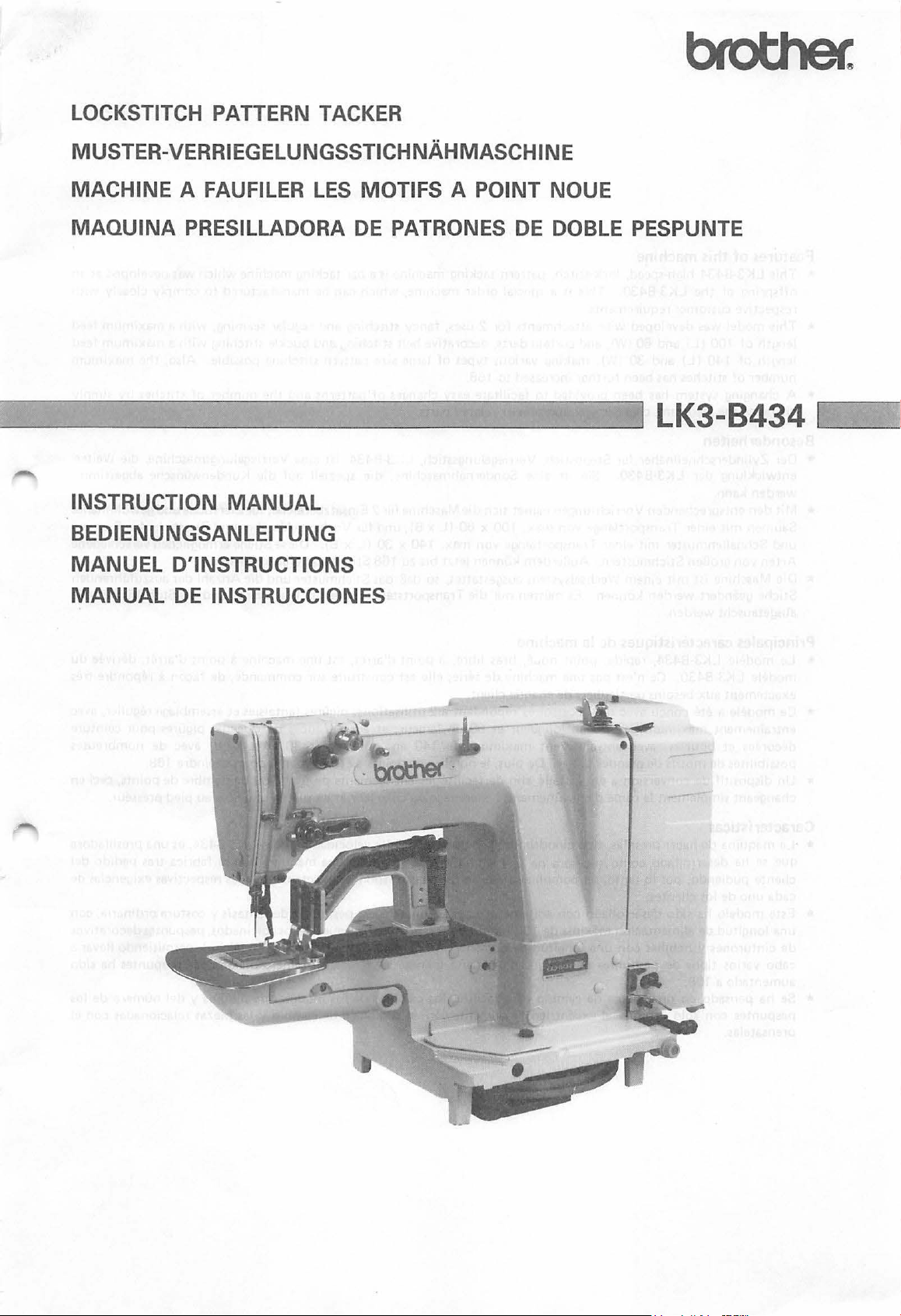
LOCKSTITCH PATTERN TACKER
MUSTER-VERRIEGELUNGSSTICHNAHMASCHINE
MACHINE
MAQUINA PRESILLADORA
--------
INSTRUCTION
BEDIENUNGSANLEITUNG
MANUEL D'INSTRUCTIONS
MANUAL
A FAUFILER
~.....__.....__
DE
LES
MOTIFS
DE
-=---
MANUAL
INSTRUCCIONES
A POINT NOUE
PATRONES
---
DE
DOBLE PESPUNTE
-
___.J
LK3-B434
~1.
----'
Page 2
Features of this machine
* This LK3-B434 high-speed, lock-stitch, pattern tacking machine
offspring of
respective customer requirements.
the
LK3-B430. This
is
a special order machine, which can be manufactured
is
a bar tacking machine which was developed as
to
comply closely with
an
* This model was developed with attachments for 2 uses, fancy stitching and regular seaming, with a maximum feed
of
100
(l)
and
60
(W),
length
length of
number
140 ( L)
of
stitches has been further increased
and
* A changing system has been provided
the
changing
feed cam, changer gear and presser-related parts.
and curtain darts, decorative belt stitching and buckle stitching with a maximum feed
30
(W), making various types
to
to
facilitate easy changes
168.
of
large size pattern stitching possible. Also,
of
patterns and
the
number
of
stitches
the
maximum
by
simply
Besonderheiten
* Der Zylinderschnellnaher fur Steppstich, Verriegelungsstich, LK3-B434, ist eine Verriegelungsmaschine, die Weiter-
entwicklung der LK3-B430.
werden kann.
Sie ist eine Sondernahmaschine, die speziell auf die Kundenwunsche abgestimmt
* Mit den entsprechenden Vorrichtungen eignet sich die Maschinefur 2 Einsatzbereiche: fur Zierstiche und gewohnliches
Saumen mit einer Transportlange von max. 100 x
und Schnallenmuster mit einer TransportUinge von max.
Arten von
* Die Maschine ist
Stiche geandert werden konnen.
ausgetauscht werden.
grol!en Stichmustern. Aul!erdem konnen jetzt bis zu
mit
einem Wechselsystem ausgestattet, so
Es
mi.issen
60
(l
x B); und fur Vorhang-Abnaher und Zierstichefur Riemen140
x 30 (L x B). Diese Stiche ermoglichen verschiedene
168
Stiche ausgefuhrt werden.
daB
das Stichmuster
nur die Transportsteuerkurve, das Wechselrad und die Stoffdruckerteile
und
die Anzahl der auszufi.ihrenden
~
Principales caracteristiques de
*
Le
modele LK3-B434, rapide, point noue, bras libre, a point d'arret, est une machine a
modele LK3-B430.
exactement aux besoins particuliers
*
Ce
modele a ete
entrainement maximum de
decorees
possibilites
*
Un
changeant simplement
et
boucles, avec entratnement maximum
de
dispositif de conversion a ete installe afin
Ce
n'est pas une machine
con~u
avec des accessoires repondant a 2 utilisations: pigures fantaisies
motifs de grandes tailles.
Ia
Ia
machine
de
serie; elle est construite sur commande, de
de
chaque client.
100
en longueur
came d'entrainement, l'engrenage
De
plus,
et
60
en largeur;
de
le
nombre de points a ete augmente pour atteindre 168.
de
facilite
140
en longueur
les
changements
du
changeur
et
aussi frances
et
point
d'arret, derivee
fa~on
a repondre tres
et
assemblage regulier, avec
de
rideaux, pigures pour ceinture
et
30
en largeur, avec
de
motif
ou de nombre de points, ceci en
les pieces associees au pied presseur.
de
nombreuses
du
Caracteristicas
*
La
maquina
que se ha desarrollado como sucesora de
cliente pudiendo, por lo
cada uno
de
hacer presillas, tipo cilindro, doble pespunte, de alta velocidad modelo LK3-B434, es una presilladora
Ia
de
los clientes.
tanto,
ser complimentada en forma
LK3-B430. Se
trata
de
una maquina que
de
responder exactamente a las respectivas exigencias de
se
fabrica tras pedido del
* Este modelo ha sido desarrollado con aditamentos para 2 finalidades: pespuntes de fantasis y costura ordinaria, con
de
100
una longitud de alimentaci6n maxima
de
cinturones y hebillas con una longitud
de
cabo varios tipos
aumentado a 168.
pespuntes de dibujos
(largo) y
de
alimentaci6n maxima
de
* Se ha pensado en un sistema de cambio para facilitar los cambios
pespuntes con
prensatelas.
solo cambiar
el
excentrico de alimentaci6n,
60
(ancho); y pliegues
de
140
tamaiio grande. Ademas,
de
los modelos de dibujos y del numero de los
el
engranaje de cambio y las piezas relacionadas con
de
loscortinados, pespuntesdecorativos
(largo) y
el
30
(alcho), permitiendo llevar a
numero maximo
de
pespuntes ha sido
el
Page 3
Contents
of
Kinds
Power table . . . . .
Installing
Installing
Installing
Motor
Installing
Installing
Lubrication . . • . . . . . . . . . . . . . . . . . . . . . . . . 10
Trial operation . . . . . . . . . . . . . . . . . • . . . . . . .
Installing
Checking
Basic operation
Basic operation of
Basic operation
Basic operation
Installing
Upper threading . . . . . . . . . . . . . . . . . . . . . .
Selecting a needle and thread. . . . . . . . . . . . . . . . 17
Bobbin winding. . . . . . . . . . . . . . . . . . . . . . . . .
Inserting and removing
Lower thread tension . . . . . . . . . . . . . . . . . . . . .
Upper thread
Thread take-up spring. . . . . . . . . • . . . . . . . . . . .
Using
Cleaning
Rei
Needle bar height adjustment. . . . . . . . . . . . . . . .
Needle bar stroke adjustment. . . . . . . . . . . . . . . .
Needle and shuttle hook clearance adjustment . . . .
Shuttle driver and needle contact adjustment . . . . •
Shuttle race thread guide adjustment . . . . . . . . . .
Brake spirng tension adjustment. . . . . . . . . . . . . .
Needle and feed timing adjustment. . . . . . . . . . . .
Thread take-up lever adjustment. . . . . . . . . . . . . . 27
Tack length adjustment . . . . . . . . . . . . . . . . . . .
Tack width adjustment. . . . . . . . . . . . . . . . . . . .
Work clamp stroke adjustment. . . . . . . . . . . . . . .
Moving blade position adjustment. . . . . . . . . . . . .
Thread wiper adjustment . . . . . . . . . . . . . . . . . .
Changing
Changing
Trouble shooting. • • • . . . . . . . . . . . . . . . . . • • .
machines
the
the
the
pulley and
the
the
the
the
the
and lower threading. . . . . . . . . . . . . . . . . . . .
the
stop lever . . . . . . . . . . . . . . . . . . . . . .
the
pacing
the
the
the
and needle hole
......................
..
. . . . . . . . . . . . . . . . . . . . . 5
motor.
machine head. . . . . . . . . . . . . . . • . 7
motor pulley and belts. . . . . . . . . . . 8
spool holder base . . . . . . . • . . • . . . 9
pedal . . . . . . . . . . . . . . . . . . . . . .
belt cover . . . . . . . . . . . . . . . . . . .
basic operation
needle
tension.
shuttle race. . . . . . . . . . . . . . . . . . .
fixed and moving blades . . . . . . . . .
feed cam and changer gear . . . . . . . •
presser, feed palte,
. . . . . . . . . . . . . . . . . . . . . 6
belts.
. . . . . . . . . . . . . . . . . . . 9
of
the
machine . . . . .
of
the
power presser lifter . . . . . . .
the
tension discs. . . . . . . . . . . .
of
the
clutch. . . . . . . . . . . . . . . .
of
the
moving blade . . . . . . . . . . .
......................
the
bobbin case
. . . . . . . . . . . . . . . . . • . .
plate.
. . . . . . . . . . . . . . . . . .
.
• • 17
10
11
11
12
13
14
15
16
17
18
19
19
20
20
21
21
22
23
23
24
24
25
25
26
28
28
29
30
31
32
34
35
I
nhaltsve~eichnis
Einteilung der Nahmaschinen. . . . . . . . . . . . . . . . 2
Motorgestell . . . . . . . . . . . . . . . . . . . . . . .
Aufstellung der Maschine . . . . . . . . . . . . . . . . . . 6
Aufstellung des Maschinenoberteils. . . . . . . . . . . . 7
Montage der R iemenscheibe und der Gurte . .
Motorriemenscheibe und Gurte . . . . . . . . . . . . . . 9
Spulentrager. . . • . . . . . . . . . . . . . • . . • . . . 9
Der
Montage des pedals . . . . . . . . . . . . . . . . . . . . . .
Schmierung . . . . . . . . . . . . . . . . . . . . . . . . . . . 10
Probebetr ieb. . . . . . . . . . . . . . . . . . . . . . . . . . .
Montage des Riemenschutzes. • . . • . • . . . • . . • . .
Oberpri.ifung des Nahmaschinenbetriebs. . . . . . . . .
Arbeitsweise des Stoffdri.ickerli.ifters . . . . . . . . • . .
Arbeitsweise der oberen Spannscheiben . . . . . . . . . 14
Arbeitsweise der Kupplung
Arbeitsweise des beweglichen Messers . • . . • . . • . . 16
Nadelbefestigung. . . . . . . . . . . . . . . . . . . . . . . . 17
E infadeln des Oberfadens . . . .
Nadel und Nahfaden
Der Spulvorgang . . . . . .
Einlegen und Entnehmen der Spulenkapsel
und Einfadeln des Unterfadens. . . . . . . . . . . . . 19
U nterfadenspannung . .
Oberfadenspannung. . . .
Fadenabnahmefeder. • . . . . . • . • . . • . . • . . • . • . 20
Der Stopphebel
Reinigung des Schiffchen-Laufrings. . . • . . . • . . • •
Auswechseln der beweglichen
und festen Messer . . . . . . . .
Einstellung der Nadelstangenhohe. . • . . . . . • • . . • 23
Einstellung des Nadelstangenhubs
Einstellung des Abstands zwischen Nadel
und Schiffchennase . .
Einstellung der Beri.ihrungsflache zwischen
Schiffchen-Mitnehmer und
Einstellung des Fadenfi.ihrers im
Schiffchen-Laufring. .
Einstellung der Bremsenfederspannung • . . • . . . . .
Einstellung des Nadel und
Transporteurgleichlaufs . . . .
Einstellung des Fadenabnahmehebels • • . . • . . . • • 27
Einstellung der Verriegelungslange
Einstellung der Verriegelungsweite . . . . • . . . . . . .
Hubverstellung des Stoffdri.ickerfuBes . . . . . . . . . .
Positionierung des beweglichen Messers. • . . . . . . .
Einstellung des Fadenwischers. . . . . . . . . . . . . . .
Austauschen der Transportsteuerkurve
und des Wechselrades . . . . . . . . . .
Austauschen des Stoffdri.ickers, der
Transportplatte und des Stitchlocheinsatzes. . . .
Fehlersuche . . . . . . . . . . . . . . . . . . . . . . . . . . . 37
.......
• . . • . . • . . • • . • . . . .
• . • • . • . • • . • . . . 17
• . . . . . . . . • • . • • . • . . . • • 17
• . . . . . • . . . . . • . . . . . 18
• . • • . . • . • . . . . . . • . . . 19
• . . . . . • . . . . . . . . . . .
: . . . . . . . . . . . . . . . . .
• . . . . . . • . . • . . 22
...........
• . . . • . . • . • . • • . . • . . 24
Nadel.
• . . . . . . . . . . . . . . . . .
. . . . . . . . . .
• . . • . . . . . . . • .
• • • . • . . . . . . .
• . . . 5
• . . • 8
10
11
11
12
13
15
20
21
21
•.
. 23
24
25
25
26
28
28
29
30
31
• . . . . . . . . 32
34
Page 4
Table des matieres
a
Differentes machines
Plateau
Installation
Installation
Installation
Poulie
Socle
Installation
Huilage . . . . . . . . . . . . . . . . . . . . . . . . . . . . . .
Essai
Installation
Verification des fonctions
Fonction
Fonction de base des tendeurs de fil . . . . . . . . . . .
Fonction de base
Fonction de base
Mise
Enfilage superieur . . . . . . . . . . . . . . . . . . . . . . . 17
Aiguille
Bobinage
Mise
Tension
Tension
Netfoyage
Changer les lames fixe
de
Ia
machine. . . . . . . . . . . . . . . . . . . . . 5
du
moteur
de
Ia
de
Ia
et
des courroies. . . . . . . . . . . . . . . . . . . . . . . 8
du
moteur
du
porte-bobine . . . . . . . . . . . . . . . . . . . . 9
de
Ia
de
Ia
machine . . . . . . . . . . . . . . . . . . . . . .
du
couvercle des courroies. . . . . . . . . .
de
base
en place de l'aiguille . . . . . . . . . . . . . . . . . . 17
et
fil . . . . . . . . . . . . . . . . . . . . . . . . . . 17
de
Ia
canette
en place
canette
Ressort
Utilisation
Reglage
Reglage de
Reglage
du
crochet
Reglage
navette
Reglage
Reglaye
Reglage de
aiguille-alimentation. . . . . . . . . . . . . . . . . . . .
Reglage
Reglage de
Reglage de
Reglage de
Positionnement de
Reglage
Changement
et
de l'engrenage
Changement
d'entrainement
Guide
et
et
enfilage inferieur. . . . . . . . . . . . . . .
du
fil
de
de
fit
de
du
tendeur . . . . . . . . . . . . . . . . . . . . . .
du
levier
du
logement
de
Ia
hauteur
Ia
course de
de
Ia
distance aiguille-pointe
de
du
contact
et
de l'aiguille. . . . . . . . . . . . . . . . . . .
du
guide-fit
de
Ia
tension
Ia
synchronisation
du
guide-til . . . . . . . . . . . . . . . . . . . . . .
Ia
longueur
Ia
largeur
Ia
course
de
l'ote-fil. . . . . . . . . . . . . . . . . . . . . . . 31
de
du
de
depannage. . . . . . . . . . . . . . . . . . . . . .
coudre.
. . . . . . . . . . . . . . . . . . . . 6
tete
de
poulie
du
et
courroies . . . . . . . . . . . . . . . 9
pedale . . . . . . . . . . . . . . . . . . .
du
releveur
de
l'embrayage . . . . . . . . . . . . . 15
de
Ia
lame mobile. . . . . . . . . . . . 16
. . . . . . . . . . . . . . . . . . . .
depose
du
dessous . . . . . . . . . . . . . . . . . .
dessus . . . . . . . . . . . . . . . . . . .
d'arret
de
et
de
Ia
Ia
canette . . . . . . . . . . . . . . . . .
de
l'entrainement
du
logement
du
du
du
du
pied-de-biche . . . . . . . . . .
Ia
lame mobile. . . . . . . . . . . . .
Ia
came
d'entrainement
du
changeur . . . . . . . . . . . . .
pied presseur, de
et
de
. . . . . . . . . . . . . . 3
Ia
machine . . . . . . . . . . . 7
moteur
de
base. . . . . . . . . . . . . 12
du
presseur. . . . . . . . 13
boitier
de
Ia
. . . . . . . . . . . . . . . . .
Ia
navette . . . . . . . . . .
mobile. . . . . . . . . . . . . .
Ia
barre a aiguille . . . . . . .
barre a aiguille . . . . . . . .
de
Ia
de
Ia
navette . . . .
ressort
de
frein. . . . . . . . .
point
. . . . . . . . . . . . . .
point
. . . . . . . . . . . . . . .
Ia
plaque
Ia
plaque d'aiguille . . . . . .
10
10
11
11
14
18
19
19
20
20
21
21
22
23
23
24
24
25
25
26
27
28
28
29
30
32
34
39
lndice
de
contenido
Diferentes tipos de Maquinas . . . . . . . . . . . . . . . 4
de
Ia
Mesa
Montaje del
Montaje
Montaje
La
pole a del
Base de porta-conos . . . . . . . . . . . . . . . . . . . . . . 9
Montaje del pedal . . . . . . . . . . . . . . . . . . . . . . .
Lubricacion . . . . . . . . . . . . . . . . . . . . . . . . . . . 1 0
Prueba
Montaje
Comprobacion
de
Operacion basica del levantador del
prensor de en erg
Operacion basica de los discos
de
Operacion fundamental del embrague . . . . . . . . . . 15
Operacion fundamental
Montaje
Hilo superior . . . . . . . . . . . . . . . . . . . . . . . . . . 17
La
aguja y
Como
Para insertar y sacar
can
Tension del hilo inferior . . . . . . . . . . . . . . . . . . . 19
Tension del hilo superior. . . . . . . . . . . . . . . . . . .
Muelle del tira hilo. . . . . . . . . . . . . . . . . . . . . . .
Como usar
Como limpiar
Reemplazar las cuchillas movibles y fijadas. . . . . . .
Ajuste de
Ajuste del curso de
Ajuste del espacio
de
Ajuste de
y del
Ajuste de
de
Ajuste de
Ajuste
y de
Ajuste de
Ajuste de
Ajuste de anchura de
Ajuste del curso del pie prensor . . . . . . . . . . . . . .
Ajuste de posicion
Ajuste del libra-hilo. . . . . . . . . . . . . . . . . . . . . . 31
Manera de cambiar
Cambio del prensatelas, placa de alimentacion
y
Localizacion de fallas. . . . . . . . . . . . . . . . . . . . . 41
maquina . . . . . . . . . . . . . . . . . . . . . . 5
motor.
de
Ia
de
Ia
motor
de
operacion. . . . . . . . . . . . . . . . . . . . . .
de
Ia
Ia
maquina . . . . . . . . . . . . . . . . . . . . . . . . 12
tension superior . . . . . . . . . . . . . . . . . . . .
de
Ia
el
llenar
ilia e h ilo inferior . . . . . . . . . . . . . . . . . . . 19
Ia
Ia
altura de
Ia
lanzadera . . . . . . . . . . . . . . . . . . . . . . .
Ia
contacto
Ia
Ia
lanzadera . . . . . . . . . . . . . . . . . . . . . . .
Ia
de
Ia
Ia
aguja . . . . . . . . . . . . . . . . . . . . . . . . .
Ia
Ia
alimentacion y
de
Ia
placa del agujero de
. . . . . . . . . . . . . . . . . . . . . . 6
cabeza
de
Ia
maquina. . . . . . . . . . . . 7
polea del
cubierta de correas . . . . . . . . . . . . .
de
aguja . . . . . . . . . . . . . . . . . . . . . . 17
hilo
Ia
canilla. . . . . . . . . . . . . . . . . . . . . 18
palanca
Ia
polea impulsora de
guia del hilo de
tension del freno
sincronizacion de alimentacion
palanca del tira hilo. . . . . . . . . . . . . .
largura de puntada . . . . . . . . . . . . . .
motor y de
y las correas. . . . . . . . . . . . . . 9
Ia
operacion basica
fa
. . . . . . . . . . . . . . . . . . . . . 13
de
Ia
........................
Ia
caja
de
de
parada . . . . . . . . . . . . . .
carrera
de
Ia
Ia
barra
Ia
barra
de
Ia
aguja y del gancho
de
Ia
aguja . . . . . . . . . . . . . . . .
puntada
de
Ia
cuchilla movible . . . . . . . .
el
excentrico de
el
engranaje de cambio. . . . . . . .
las correas. . . . . 8
cuchilla movible. . . . .
Ia
lanzadera . . . . . . . . .
de
Ia
aguja . . . . . . . .
de
Ia
aguja. . . . . . . . . .
Ia
lanzadera
Ia
carrera
de
muelle. . . . . . . . .
. . . . . . . . . . . . . . .
Ia
aguja. . . . . . . . . . .
10
11
11
14
16
17
20
20
21
21
22
23
23
24
24
25
25
26
27
28
28
29
30
32
34
Page 5
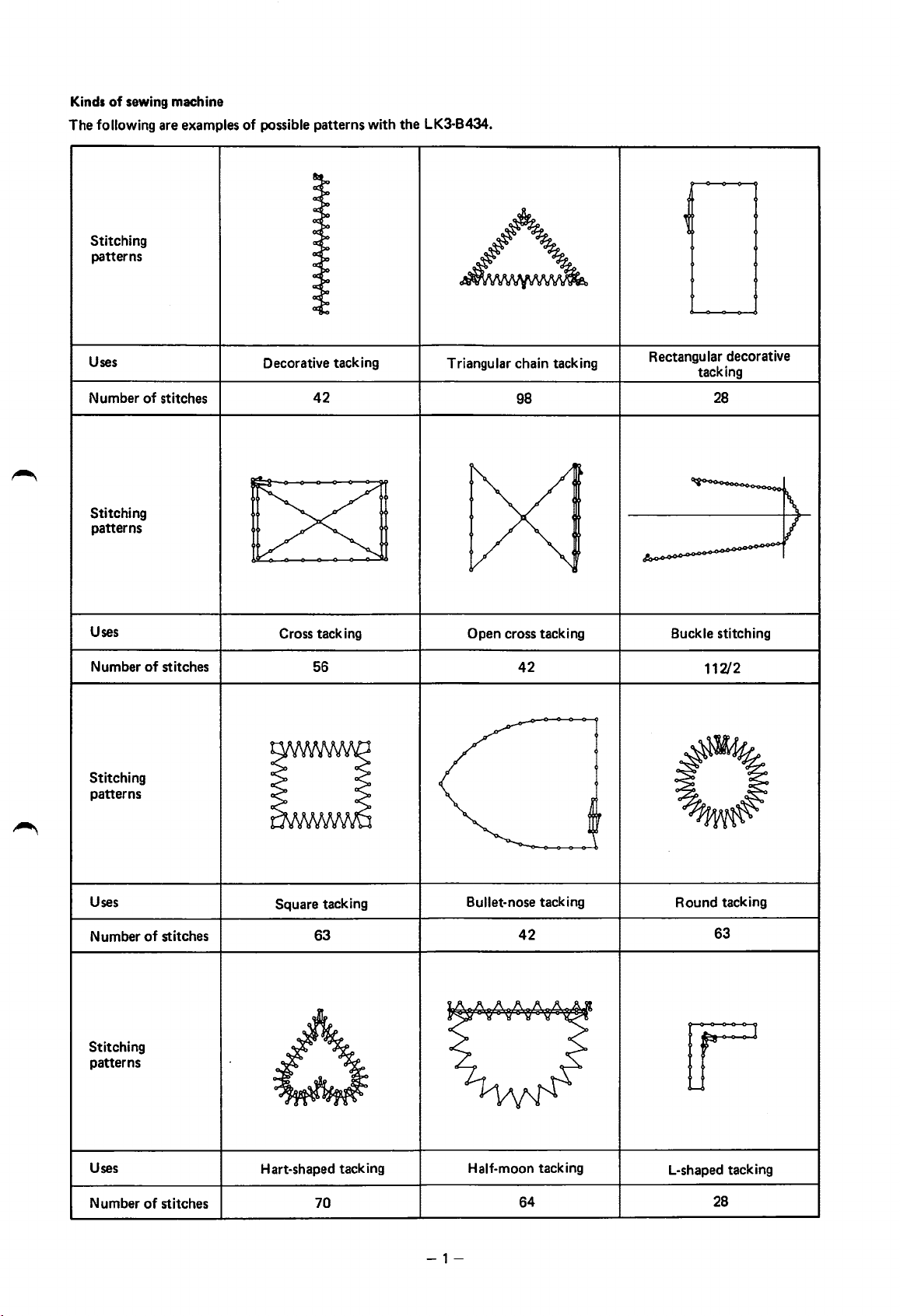
Kinds
of
sewing machine
The
following are examples
Stitching
patterns
of
possible patterns with
the
LK3-B434.
Uses
Number
Stitching
patterns
Uses
Number
Stitching
patterns
of
stitches
of
stitches
Decorative tacking
42
Cross tacking Open cross tacking
56 42
Triangular chain tacking
98
Rectangular decorative
tacking
28
Buckle stitching
112/2
Uses
Number
Stitching
patterns
Uses
Number
of
stitches
of
stitches
D
Square tacking
63
Hart-shaped tacking
70
Bullet-nose tacking
Half-moon tacking
-1-
42
64
0
Round tacking
63
L-shaped tacking
28
Page 6
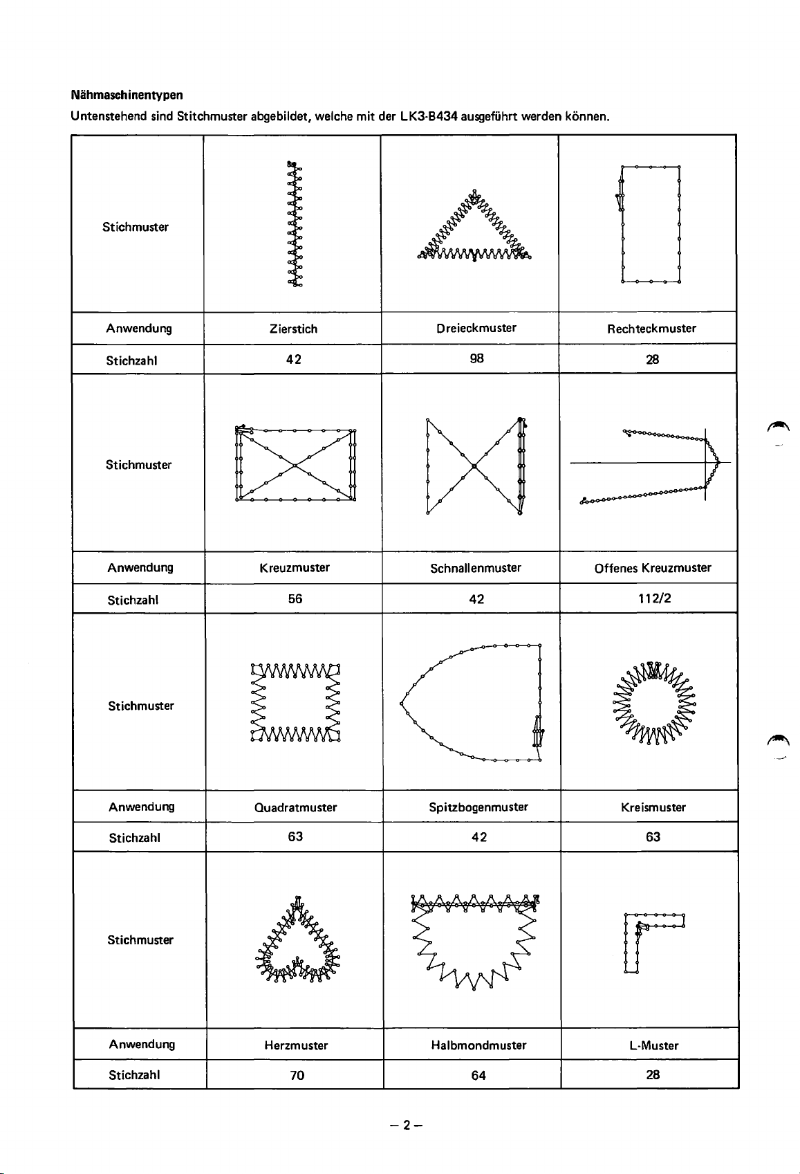
Niihmaschinentypen
Untenstehend sind Stitchmuster
Stichmuster
abgebildet, welche mit der LK3-B434 ausgeffihrt werden konnen.
Anwendung
Stichzahl
Stichmuster
Anwendung
Stichzahl
Stichmuster
Zierstich
42
Kreuzmuster
56
Dreieckmuster
98
Schnallenmuster Offenes Kreuzmuster
42
Rechteckmuster
28
112/2
Anwendung
Stichzahl
Stichmuster
Anwendung
Stichzahl
D
Quadratmuster
63
Herzmuster
70 64
Spitzbogenmuster
Halbmondmuster
-2-
42
0
Kreismuster
63
L-Muster
28
Page 7
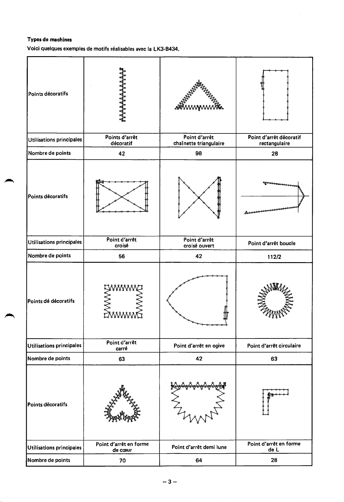
Types
de
machines
Voici
quelques exemples de motifs n!alisables avec
Points decoratifs
Ia
LK3-8434.
Utilisations
Nombre
Points decoratifs
Utilisations principales
Nombre
Points
principales
de
points
de
points
de
decoratifs
Points d'arret
decor
at
if
42
Point d'arret
croise
56
Point d'arret
chalnette
Point d'arret
croise ouvert
triangulaire
98
42
Point d'arret decoratif
rectangulaire
28
Point d'arret boucle
112/2
Utilisations principales
Nombre
Points decoratifs
Utilisations principales
Nombre
de
de
points
points
D
Point d'arret
carre
63
Point d'arret en forme
de
cmur
70
Point d'arret en ogive
42
Point d'arret demi lune
64
-3-
0
Point
d'arret
circulaire
63
Point d'arret en forme
deL
28
Page 8
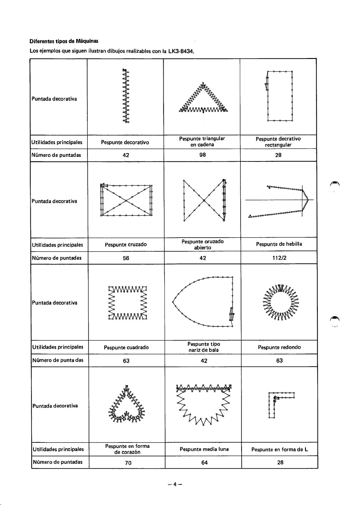
Diferentes tipos
Los ejemplos
Puntada decorativa
de
que
Maquinas
siguen ilustran dibujos realizables con
Ia
LK3-B434.
Util idades principales
de
Numero
Puntada decorativa
Util idades principales
Numero
Puntada decorativa
puntadas
de
puntadas
Pespunte decorative
42
Pespunte cruzado
56
Pespunte triangular
en cadena
98
Pespunte oruzado
abierto
42
Pespunte decrativo
rectangular
28
Pespunte
de
112/2
hebilla
Utilidades principales
Numero
Puntada decorativa
Utilidades principales
Numero
de
punta
de
puntadas
das
D
Pespunte cuadrado
63
Pespunte en forma
de
coraz6n
70
Pespunte
nariz
Pespunte media luna
-4-
de
42
64
tipo
bala
0
Pespunte redondo
63
Pespunte en forma
28
de
L
Page 9
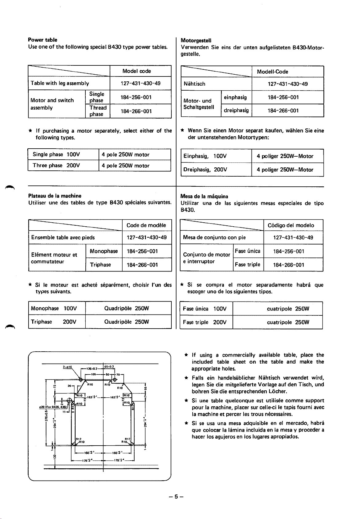
Power table
Use
one
of
the
following special
8430
type power tables.
Motorgestell
Verwenden Sie eins der unten aufgelisteten 8430-Motorgestelle.
Model code
leg
Table with
Motor and switch
assembly
*
If
purchasing a motor separately, select either of
following types.
Single phase 1
Three phase
Plateau de
Utiliser une des tables de
Ensemble table avec pieds
assembly
200V
Ia
machine
OOV
Single
phase
Thread
phase
4 pole 250W motor
4 pole 250W motor
type
127-431-430-49
184-256-001
184-266-001
8430
speciales suivantes.
Code
127-431-430-49
de
modele
Modeii-Code
Nahtisch
Motor- und
Schaltgestell
* Wenn Sie einen Motor separat kaufen, wahlen Sie eine
the
der untenstehenden Motortypen:
Einphasig, 1
Dreiphasig, 200V
Mesa
de
Ia
Utilizar una de
8430.
Mesa de conjunto con pie 127-431-430-49
einphasig
dreiphasig
OOV
maquina
las
siguientes mesas especiales de tipo
127-431-430-49
184-256-001
184-266-001
4 poliger
4 poliger
250W-Motor
250W-Motor
C6digo del modelo
Element moteur et
commutateur
*
Si
le
moteur est achete separement, choisir l'un des
types suivants.
Monophase 1
Triphase
OOV
200V
Monophase 184-256-001
Triphase
Ouadripole 250W
Ouadripole 250W
184-266-001
Conjunto de motor
e interruptor
*
Si
se
compra
escoger uno de los siguientes tipos.
F
ase
(an
ica 1 OOV
Fase triple 200V cuatripole 250W
*
If
using a commercially available table, place
included table sheet
appropriate holes.
Fase (mica 184-256-001
1-------+-----------1
Fase triple
el
motor
on
184-266-001
separadamente habra que
cuatripole 250W
the
table and make
* Falls ein handelsiiblicher Nahtisch verwendet wird,
legen
Sie die mitgelieferte Vorlage auf den Tisch, und
bohren
*
Si
*
Si
que colocar
hacer los agujeros en los lugares apropiados.
Sie die entsprechenden Locher.
une table quelconque est utilisee comme support
Ia
pour
Ia
machine, placer sur celle-ci
machine
se usa una mesa adquisible en
et
percer les trous necessaires.
Ia
lamina incluida en
le
tapis fourni avec
el
mercado, habra
Ia
mesa y proceder a
the
the
-5-
Page 10
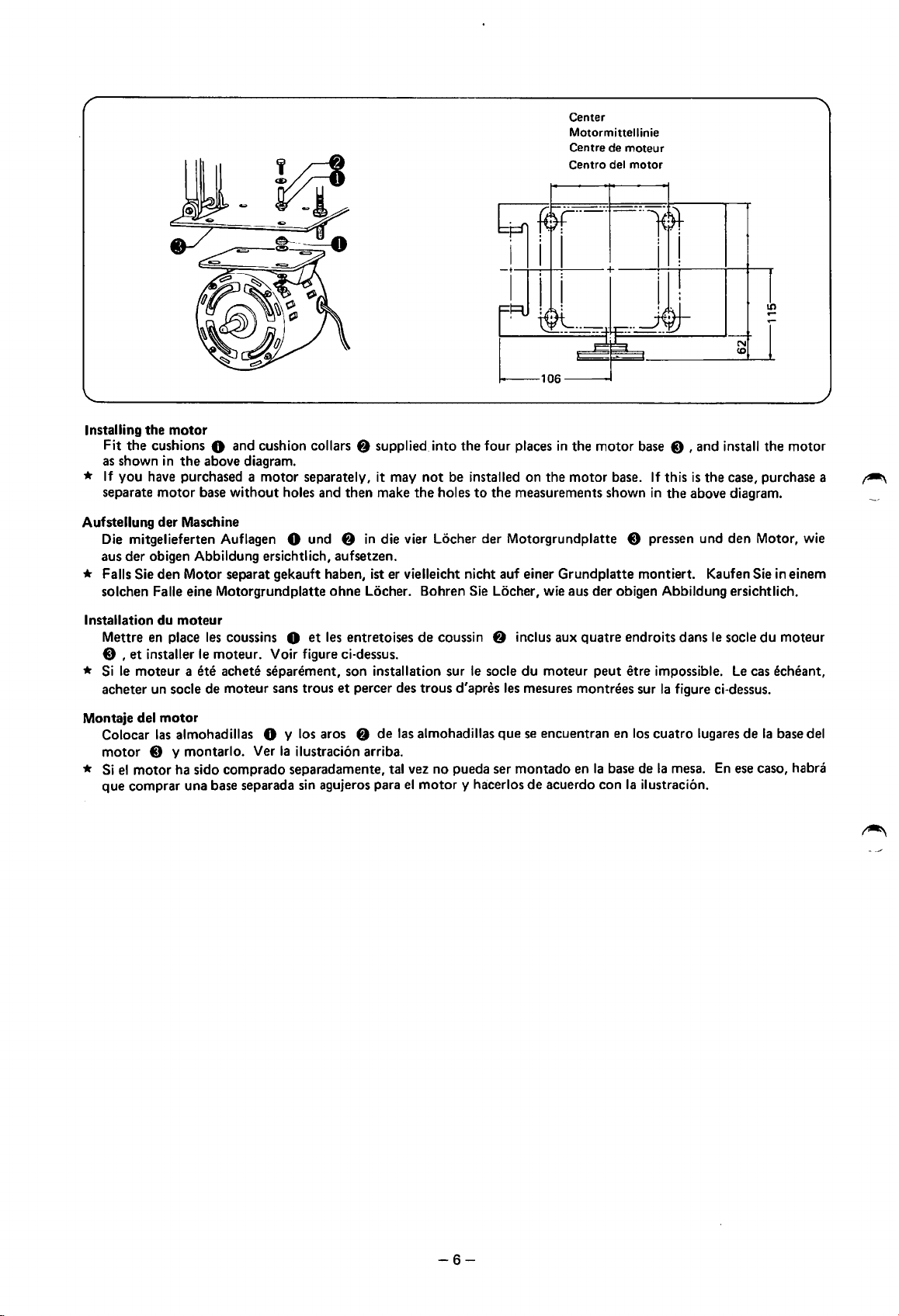
Center
Motormittellinie
Centre
de
moteur
Centro del
motor
U')
..-
N
(0
Installing
*
Aufstellung der Maschine
the
motor
Fit
the
as shown
If
separate
Die mitgelieferten
aus
cushions 0 and cushion collars
in
the
above diagram.
you have purchased a
motor
base
der
obigen Abbildung ersichtlich, aufsetzen.
motor
separately, it may
without
Auflagen 0 und
holes and
f)
supplied. into
then
make
f)
in
die vier Locher der Motorgrundplatte 0 pressen und
not
the
holes
the
four places
be installed
to
on
the
the measurements shown
in
the
motor
motor
base.
base 0 , and install the
If
this
is
the
case, purchase a
in
the
above diagram.
den
Motor, wie
motor
* Falls Sie den Motor separat gekauft haben, ist er vielleicht nicht auf einer Grundplatte montiert. Kaufen Sie in einem
solchen
Installation du
Mettre en place
0 ,
*
Si
acheter un socle de moteur sans trous
Montaje del
Colocar
motor
*
Si
que
Faile eine Motorgrundplatte
moteur
les
coussins 0
et
installer
le
moteur a
0 y montarlo. Ver
el
motor
comprar una base separada sin agujeros para
le
moteur. Voir figure ci-dessus.
ete
achete separement, son installation sur
motor
las
almohadillas 0 y los aros
Ia
ha sido comprado separadamente, tal vez no pueda ser
ohne
Locher. Bohren Sie Locher, wie aus
et
les entretoises
et
percer des trous d'apres les mesures montrees sur
f)
ilustraci6n arriba.
de
coussin
de
las almohadillas
el
motor
f)
inclus aux
le
socle
que
montado
y hacerlos
der
obigen Abbildung ersichtlich.
quatre
endroits dans
du
moteur
se encuentran en los
de
acuerdo
en
peut
etre impossible.
Ia
base de
con
Ia
Ia
figure ci-dessus.
cuatro
lugares
Ia
mesa.
ilustraci6n.
le
socle
du
Le
cas echeant,
de
Ia
En
ese caso, habra
moteur
base del
~
-6-
Page 11
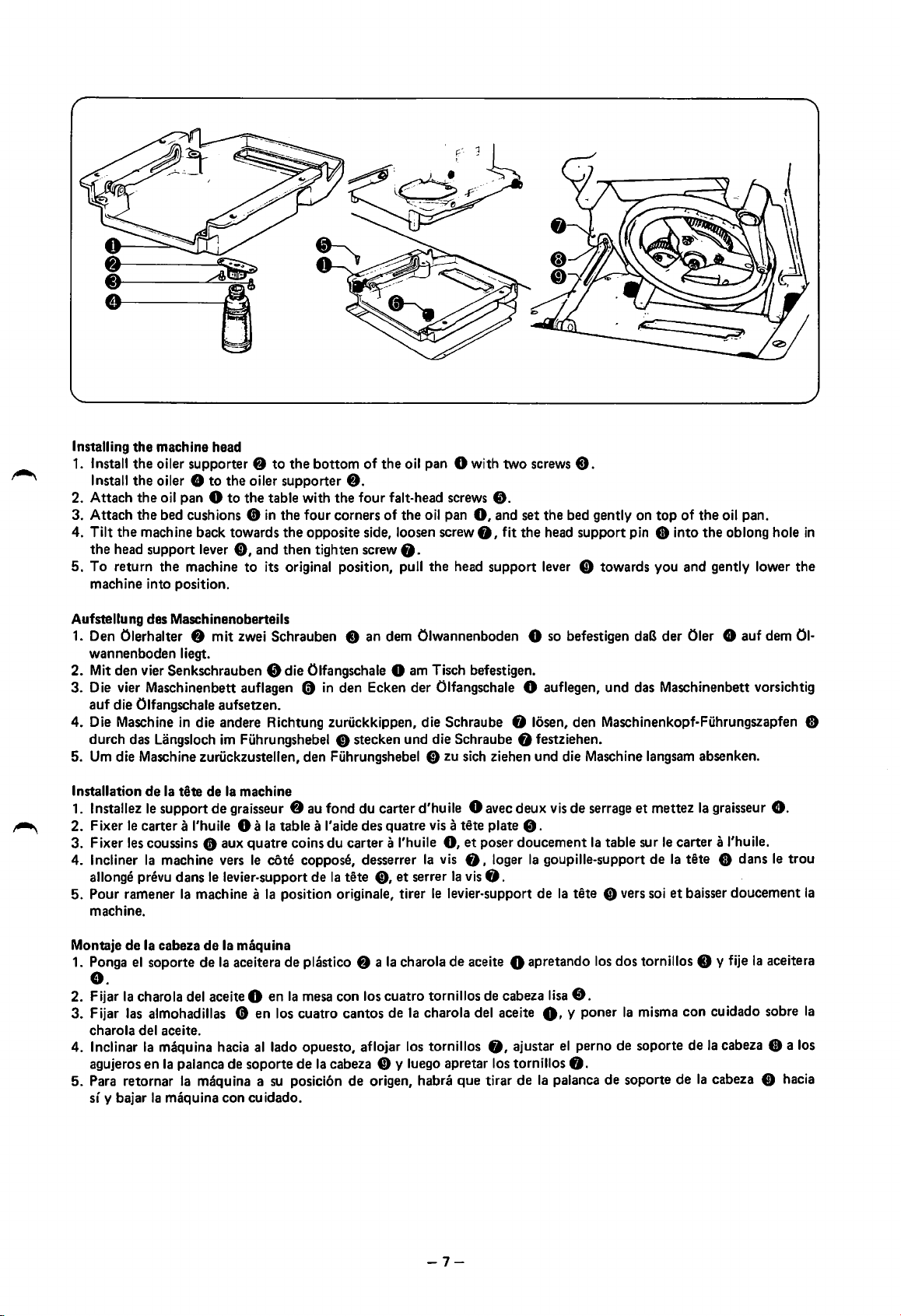
Installing
1.
2.
3.
4. Tilt
5.
Aufstellung des Maschinenoberteils
1. Den
2.
3.
4.
5. Um die Maschine
the
machine head
Install
the
oiler supporter
Install the oiler e
Attach
Attach
the
To
machine into position.
wannenboden liegt.
Mit den vier Senkschrauben 0 die Olfangschale 0 am Tisch befestigen.
Die vier Maschinenbett auflagen 0
auf
Die Maschine
durch das Uingsloch
the
oil pan 0
the
bed cushions
the
machine back towards
head support lever
return
the
machine
Olerhalter
die Olfangschale aufsetzen.
f)
in
die andere Richtung zuruckkippen, die Schraube 8 losen,
zuruckzustellen, den Fuhrungshebel 0 zu sich ziehen und die Maschine Iangsam absenken.
f)
to
the
bottom
to
the
oiler supporter
to
the
table with
(tin
the four corners
the
opposite side, loosen screw
0,
and
then
tighten screw
to
its original position, pull
mit
zwei Schrauben 8
im
Fuhrungshebel 0 stecken und die Schraube 8 festziehen.
in
f).
the
den
of
the
oil pan 0 with
four
fait-head screws
of
the
oil pan
0,
0,
0.
the
head
support
an
dem Olwannenboden 0 so befestigen
Ecken
der
Olfangschale 0 auflegen,
two
8.
and set
fit
the
screws
the
bed gently on
head
lever
8.
top
of
the
oil pan.
support
Ci)
den
pin 8 into
towards you and gently lower
daB
und
das Maschinenbett vorsichtig
Maschinenkopf-Fuhrungszapfen 0
der
the
Oler 0
oblong hole
auf
dem
in
the
01-
~
Installation
lnstallez
1.
2.
Fixer
3. Fixer les coussins
4.
Incliner
allonge prevu
5. Pour ramener
machine.
Montaje
1. Ponga
de
Ia
tate
de
Ia
le
support
le
carter a l'huile 0 a
Ia
machine vers
de
Ia
cabeza
el
soporte
de
(t
dans
le
Ia
machine a
de
de
aux
levier-support
Ia
Ia
graisseur
aceitera de plastico
e.
2.
Fijar
Ia
charola del aceite 0
3. Fijar las almohadillas 0
charola del aceite.
4. lnclinar
agujeros
5. Para retornar
sf y bajar
Ia
maquina hacia al lado opuesto, aflojar los tornillos
en
Ia
palanca de soporte
Ia
maquina a
Ia
maquina con cu idado.
machine
f)
au fond
Ia
table a
I'
quatre
coins
du
le
cote
coppose, desserrer
de
Ia
position originate, tirer
maquina
en
Ia
mesa con los
en
los cuatro
de
Ia
cabeza 0 y luego apretar los tornillos
su
posicion
aide
carter
Ia
tete
cantos
de
du
des
f)
carter d'huile 0 avec
quatre
vis a tete plate
a l'huile
0,
et
a
Ia
cuatro
de
origen, habra
0,
et
poser
Ia
vis
8,
serrer
Ia
vis
8.
le
levier-support
charola
de
aceite 0 apretando los
tornillos de cabeza lisa
Ia
charola del aceite O, y
que
tirar
deux
doucement
loger
0,
ajustar
de
vis
de
serrage
8.
Ia
Ia
goupille-support
de
Ia
tete
8.
poner
el
perno de soporte
8.
Ia
palanca
et
mettez
table sur
de
0 vers soi
dos
tornillos 0 y fije
Ia
misma
de
soporte
Ia
graisseur
le
carter a l'huile.
Ia
tete 0 dans
et
baisser
doucement
con
cuidado sobre
de
Ia
cabeza 8 a los
de
Ia
cabeza 0 hacia
e.
le
Ia
aceitera
trou
Ia
Ia
-7-
Page 12
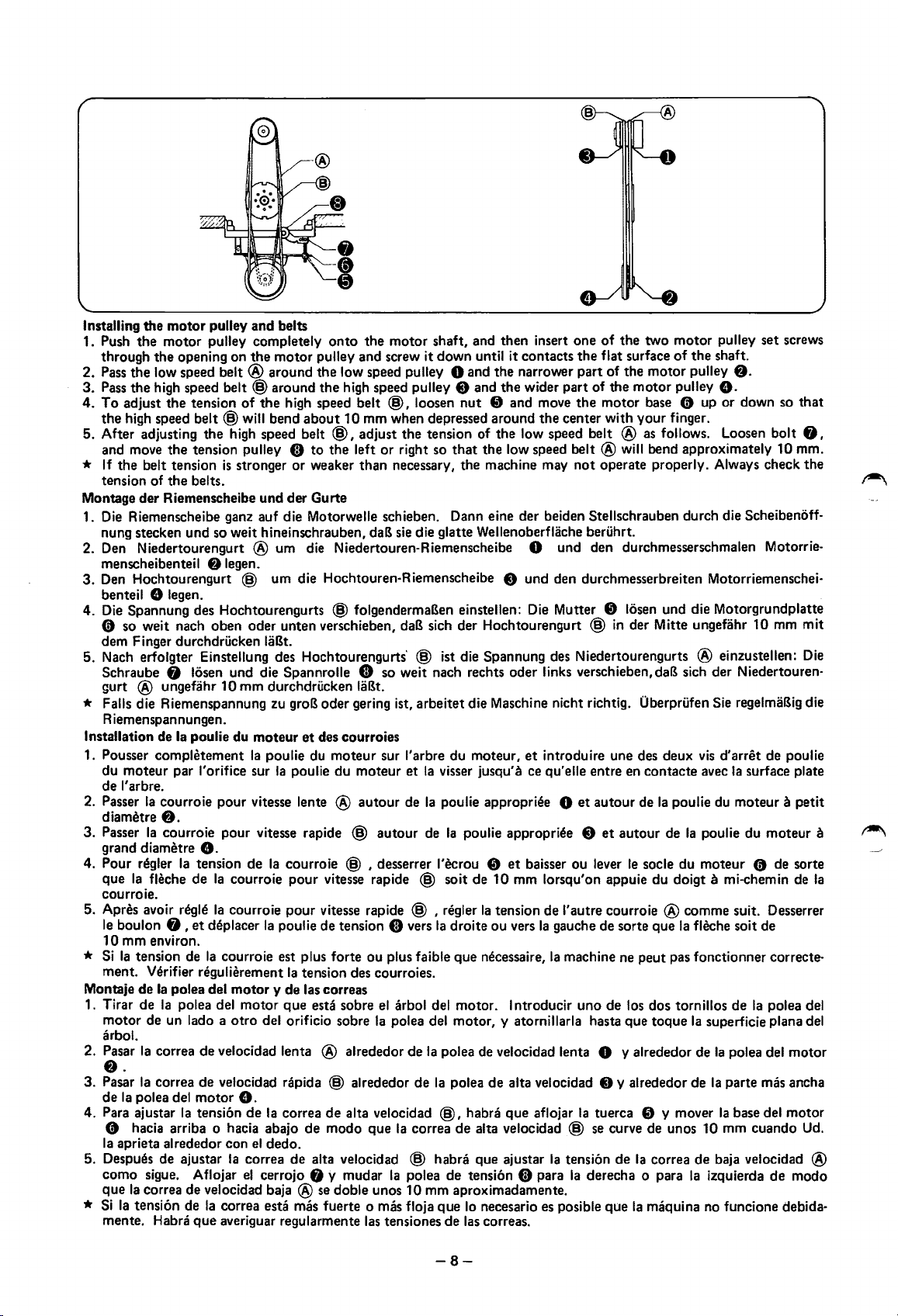
Installing
1. Push
2.
3.
4.
5. After adjusting
* If
Montage
1. Die Riemenscheibe ganz auf die
2. Den Niedertourengurt
3.
4.
5. Nach erfolgter Einstellung des Hochtourengurts' @ ist die Spannung des Niedertourengurts ® einzustellen: Die
* Falls die Riemenspannung zu groB
Installation de
1. Pousser
2. Passer
3.
4. Pour regler
5.
*
Montaje
1. Tirar
2. Pasar
3.
4.
5. Despues de ajustar
*
the
motor
the
through
Pass
Pass
To
the
and move
tension of
nung stecken
menscheibenteil
Den Hochtourengurt @ um die Hochtouren-Riemenscheibe 8
benteil
Die Spannung des Hochtourengurts @ folgendermaBen einstellen: Die Mutter 8 losen und die Motorgrundplatte
the
the
low speed
the
high speed
adjust
high speed
the
belt tension
der
8 legen.
0 so weit nach
dem Finger durchdrucken laBt.
Schraube
gurt
® ungefahr
R iemenspannungen.
du
de
diametre
Passer
grand diametre
que
courroie.
Apres avoir regie
le
1
Si
ment. Verifier
motor
arbol.
f).
Pasar
de
Para ajustar
comph!tement
moteur par l'orifice sur
l'arbre.
Ia
courroie
f).
Ia
Ia
fleche
boulon 8 ,
0 mm environ.
Ia
tension de
de
Ia
de
Ia
de un lado a
Ia
correa
Ia
correa
Ia
polea del
0 hacia arriba o hacia abajo
Ia
aprieta alrededor con
como
sigue. Aflojar
que
Ia
correa
Si
Ia
tension de
mente. Habra
pulley and belts
motor
pulley completely
opening
the
the
the
Riemenscheibe
on
belt®
belt@
tension
belt@
tension pulley C)
belts.
und
of
will bend
the
high speed belt
is
stronger
so weit hineinschrauben, daB sie die glatte Wellenoberflache beruhrt.
f)
legen.
oben
the
motor
around
around
the
und
® um die Niedertouren-Riemenscheibe 0 und den durchmesserschmalen Motorrie-
oder
unten verschieben,
onto
the
motor
shaft, and then insert
pulley and screw it
the
low speed pulley 0 and
the
high speed pulley 8 and
high speed belt
about
@,
to
the
or
weaker
der
Gurte
Motorwelle schieben. Dann eine der beiden Stellschrauben durch die Scheibenoff-
@,
10
mm when depressed around
adjust
left
or
than
down
until
it
contacts
the
narrower
the
wider
loosen
nut
8 and move
the
tension of
right so
necessary, the machine may
daB
sich der Hochtourengurt @
that
the
low speed belt ®
the
low speed belt
und
one
of
the
two
motor
pulley
set
the
flat surface
part
of the
part
of
the
the
motor
the
center with
®will
not
operate properly. Always check
den durchmesserbreiten Motorriemenschei-
in
of
the
pulley
pulley
finger.
shaft.
f).
e.
10
motor
motor
base 0 up or down so
your
as
follows. Loosen
bend approximately 10 mm.
der Mitte ungefahr
screws
bolt
mm
that
8,
the
mit
8 losen und die Spannrolle 0 so weit nach rechts oder links verschieben, daB sich der Niedertouren-
10
mm durchdrucken laBt.
oder
gering ist, arbeitet die Maschine nicht richtig. Oberprufen Sie regelmaBig die
Ia
poulie du
courroie
moteur
Ia
poulie du
Ia
pour
vitesse lente ®
pour
vitesse rapide @
et
des courroies
moteur
poulie
du
sur l'arbre
moteur
autour
autour
du
et
de
Ia
moteur,
visser jusqu'a ce qu'elle entre en
Ia
poulie appropriee 0
de
Ia
poulie appropriee 8
et
introduire une des deux
et
autour
et
autour
contacte
de
vis
avec
Ia
poulie du moteur a
de
Ia
poulie du moteur a
d'arret
Ia
surface plate
de poulie
petit
e.
Ia
tension
de
et
regulierement
polea del
polea del
de
de
motor
Ia
tension
de
que
de
Ia
Ia
courroie
Ia
courroie
deplacer
Ia
courroie est plus forte
motor
otro
velocidad lenta ® alrededor
velocidad rapida @ alrededor
courroie @ , desserrer l'ecrou 8
pour
vitesse rapide @ soit de
pour
vitesse rapide @ , n!gler
Ia
poulie de tension 0 vers
ou
plus faible
Ia
tension des courroies.
y de las correas
motor
que
esta sobre
del orificio sobre
el
arbol del motor. lntroducir
Ia
polea del motor, y atornillarla hasta que
8.
de
Ia
correa
de
alta velocidad
de
modo
que
el
dedo.
Ia
correa
de
alta velocidad @ habra que ajustar
el
velocidad baja ®
Ia
cerrojo 8 y mudar
Correa esta mas fuerte 0 mas floja
averiguar regularmente las tensiones
se
doble unos 10 mm aproximadamente.
Ia
Ia
et
baisser
ou
10
mm lorsqu'on appuie
Ia
tension
Ia
droite
ou
que
necessaire,
de
Ia
polea de velocidad lenta 0 y alrededor
de
Ia
polea
de
@,
correa
polea
habra
de
alta velocidad @
de
tension 0 para
que
lo
necesario es posible
de
las correas.
de
vers
Ia
alta velocidad 8 y alrededor
que
aflojar
lever
I'
autre courroie ® comme suit. Desserrer
gauche de sorte que
Ia
machine ne
uno
de
Ia
tuerca 8 y mover
se
curve de unos 10 mm cuando Ud.
Ia
tension
Ia
derecha o para
que
le
socle du moteur 0 de sorte
du
doigt a mi-chemin de
Ia
fleche soit de
peut
pas fonctionner correcte-
los dos tornillos de
toque
Ia
superficie plana del
de
de
de
Ia
correa
de
Ia
Ia
maquina no funcione debida-
Ia
Ia
polea del
Ia
parte mas ancha
Ia
base del
baja velocidad ®
izquierda
polea del
motor
motor
de
modo
~
~
Ia
-8-
Page 13
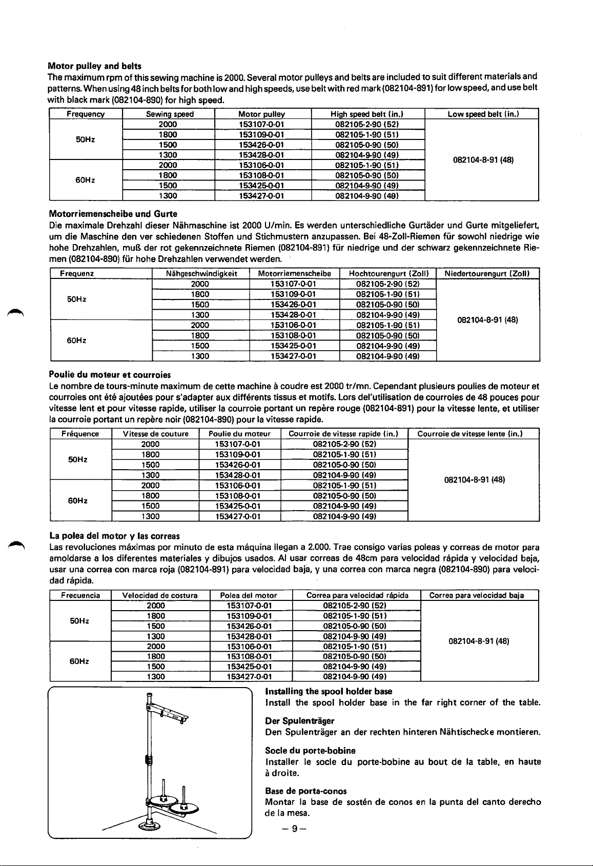
Motor pulley and belts
The maximum rpm
patterns. When using
with
black mark (082104-890)
Frequency
50Hz
60Hz
of
this sewing machine is 2000. Several
48
inch belts
Sewing
for
both
low
and high speeds, use belt
for
high speed.
speed
2000
1800
1500 153426-0-01 082105-0-90 (50)
1300 153428-0-01 082104-9-90
2000 153106-0-01 082105-1-90 (51)
1800
1500 153425-0-01
1300 153427-0-01
Motor
153107-0-01 082105-2-90
1531 09-0-01
153108-0-01 082105-0-90 (50)
motor
pulleys and belts are included to suit different materials and
with
pulley High
082105-1-90
0821 04-9-90
082104-9-90
red mark
speed
belt (in.)
(0821
(52)
(51)
(49)
( 49)
(49)
04-891)
for
low
speed, and use belt
Low
speed
082104-8-91 (48)
belt
Motorriemenscheibe und Gurte
Die maximale Orehzahl dieser Nahmaschine ist 2000 U/min.
urn die Maschine den ver schiedenen Stoffen und Stichmustern anzupassen.
hohe Drehzahlen,
(082104-890) fUr hohe Drehzahlen verwendet werden. -
man
Frequenz Nahgeschwindigkeit Motorriemenscheibe Hochtourengurt (Zoll) Niedertourengurt (Zoll)
50Hz
60Hz
muB der rot gekennzeichnete Riemen (082104-891) fUr niedrige und der schwarz gekennzeichnete Rie-
2000
1800
1500
1300
2000
1800
1500
1300
Es
werden unterschiedliche Gurtader und Gurte mitgeliefert,
Bei
48-Zoii-Riemen
153107-0-01 082105·2-90
153109-0-01 082105-1-90
153426-0-01 082105-0-90 (50)
1534 28·0·0 1 082104-9-90 (49)
153106-0-01 082105-1-90 (51)
1531 08-0-01 0821 05·0-90 (50)
153425-0-01
153427-0-01 082104-9-90
082104-9-90
(52)
(51)
(49)
(49)
fur
sowohl niedrige wie
082104-8-91 (48)
(in.)
~
Poulie du moteur
Le
nombre de tours-minute maximum de cette machine a coudre est 2000
courroies ont
vitesse lent
Ia
courroie portant un repere noir (082104-890) pour
Fn!quence
50Hz
60Hz
La
polea del motor y
Las
revoluciones maximas por minuto de esta maquina llegan a
amoldarse a los diferentes materiales y dibujos usados.
usar una correa con marca roja
et
courroies
ete ajoutees pour s'adapter aux differents tissus
et
pour vitesse rapide, utiliser
Vitesse de couture
2000
1800 153109-0-01
1500 153426-0·01
1300
2000
1800
1500
1300 153427-Q-01
las
correas
Ia
courroie portant un repere rouge (082104-891) pour
Ia
vitesse rapide.
Poulie du moteur Courroie de vitesse rapide (in.) Courroie de vitesse lente (in.)
153107-0-01
153428-Q-01
153106-0-01
153108-0·01
153425-0-Q
1
(082104-891) para velocidad baja, y una correa con marca negra (082104-890) para veloci-
et
motifs. Lors del'utilisation de courroies de 48 pouces pour
082105-2-90
082105-1-90
082105-0-90 (50)
082104-9-90
082105-1-90
082105-0-90 (50)
082104-9-90 (49)
082104-9-90
2.000.
AI
usar correas de 48cm para velocidad rapida y velocidad baja,
dad rapida.
Frecuencia Velocidad
50Hz
60Hz
2000
1800
1500
1300
2000
1800
1500
1300
de
costura
Poles del
153107-0-01
09-0·0 1
1531
153426-Q-01
153428-0-01
1531 06-0·01
1531
08-Q-0
153425-0-01
153427-Q-01
motor
1 082105-0-90 (50)
Correa para velocidad rapids Correa para velocidad baja
Installing the spool holder base
Install the spool holder
tr/mn.
Cependant plusieurs poulies de moteur et
Ia
vitesse lente,
(52)
(51)
(49)
(51)
(49)
082104-8-91 (48)
Trae consigo varias poleas y correas de
082105-2-90
082105-1-90 (51)
082105-0-90 (50)
082104-9·90
082105-1-90
082104-9-90
082104-9-90
(52)
(49)
(51)
(49)
(49)
base
in the far
082104-8-91
right
corner
et
motor
(48)
of
the table.
utiliser
para
Der Spulentrager
Den Spulentrager an der rechten hinteren Nahtischecke montieren.
Socle du porte-bobine
Installer
a
droite.
Base
Montar
de
le
socle
de porta-conos
Ia
base
Ia
mesa.
du
porte-bobine
de sosten de conos
-9-
au
bout
de
Ia
table,
en
Ia
punta del canto derecho
en
haute
Page 14
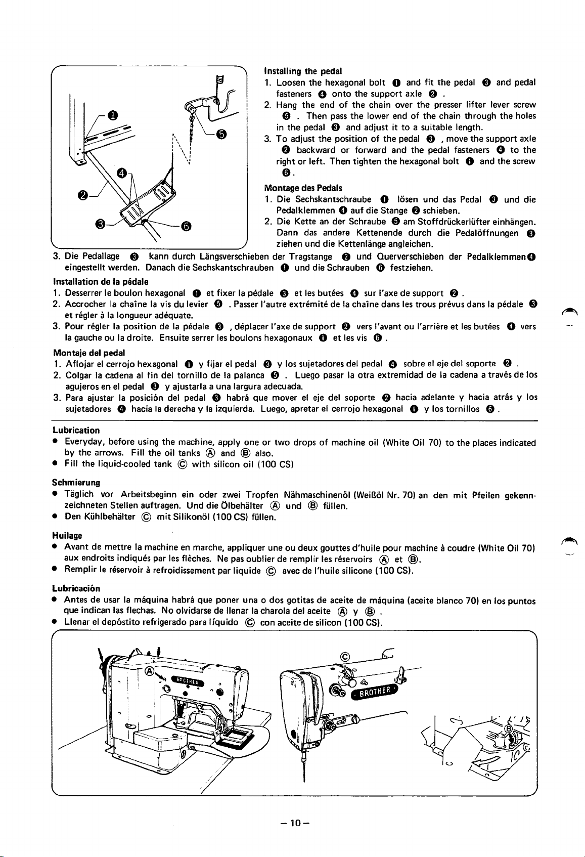
Installing the pedal
1.
Loosen the hexagonal bolt 0 and fit the pedal 0 and pedal
e onto the support axle
the end of the chain over the presser lifter lever screw
. Then pass the lower end of the chain through the holes
backward or forward and the pedal fasteners e
.
1\
I\
I \ I
I \ I
\\;
fasteners
2.
Hang
f)
in
the pedal 0 and adjust it to a suitable length .
3.
I
To adjust the position of the pedal 0 , move the support axle
f)
right or left. Then tighten the hexagonal bolt
0.
Montage des Pedals
1.
Die
Sechskantschraube 0 losen und das
Pedalklemmen
2.
Die
Kette an der Schraube
Dann
das
ziehen und die Kettenlange angleichen.
Die
Pedallage 0 kann durch Langsverschieben der Tragstange
3.
eingestellt werden. Danach die Sechskantschrauben 0 und die Schrauben 0 festziehen.
Installation de
1.
Desserrer
2. Accrocher
et
regler a
3. Pour
Ia
gauche ou
Ia
pedale
le
boulon hexagonal 0 et fixer
Ia
chaine
Ia
vis
du levier
Ia
longueur adequate.
n!gler
Ia
position de
Ia
droite. Ensuite serrer
Ia
Ia
f)
pedale 8 et
. Passer
I'
autre extremite de
les
pedale 8 I deplacer l'axe de support
les
boulons hexagonaux 0 et
Montaje del pedal
1.
Aflojar
2. Colgar
agujeros en
3. Para ajustar
sujetadores 8 hacia
el
cerrojo hexagonal 0 y fijar
Ia
cadena
al
fin del tornillo de
el
pedal 0 y ajustarla a una largura adecuada.
Ia
posicion
del
pedal 0 habra que mover
Ia
derecha y
el
Ia
Ia
izquierda.
pedal 0 y
palanca
f)
Luego,
los
sujetadores
.
Luego
el
apretar
8 auf die Stange
f)
andere Kettenende durch die Pedaloffnungen 0
f)
und Ouerverschieben der Pedalklemmen8
butees 8 sur l'axe de support
Ia
chaine dans
f)
vers
l'avant ou l'arriere et
les
vis
0 .
del
pedal 8 sobre
pasar
Ia
otra extremidad de
eje
del
soporte
el
cerrojo hexagonal 0 y
f)
hacia adelante y hacia atras y
f)
.
0 and the screw
Pedal
0 und die
f)
schieben.
am
Stoffdruckerlufter einhangen.
f)
.
les
trous prevus dans
el
eje del soporte 8 .
Ia
cadena a traves de los
los
tornillos 0 .
les
butees e
Ia
pedale 8
to
the
vers
los
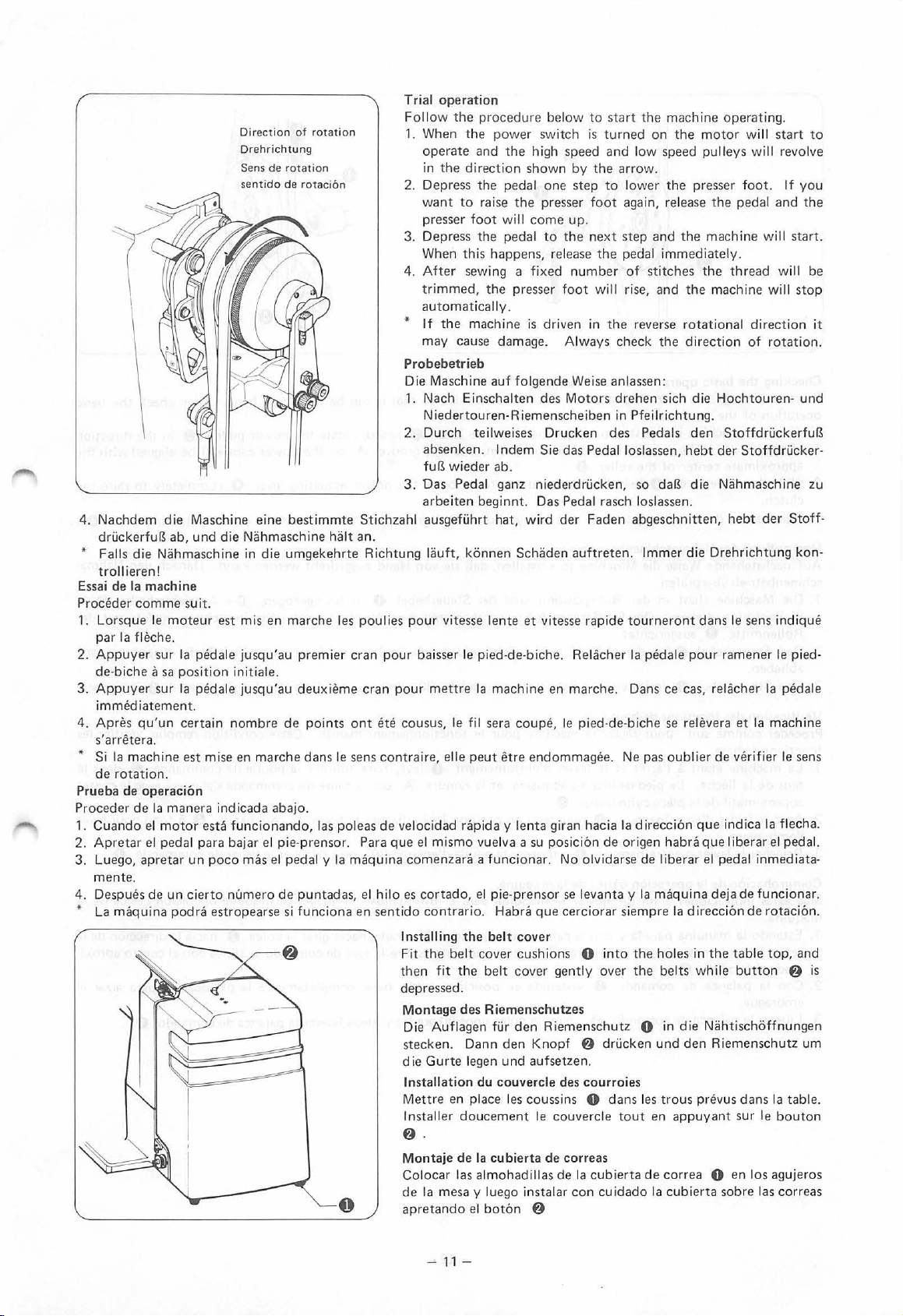
Lubrication
• Everyday, before
by the arrows.
•
Fill
the liquid-cooled tank © with silicon
using
Fill
Schmierung
• Taglich
vor
Arbeitsbeginn ein oder
zeichneten Stellen auftragen.
Den
•
Kuhlbehalter © mit Silikonol (100
Huilage
•
Avant de mettre
Ia
machine
aux endroits indiques par
• Remplir
le
reservoir a refroidissement par liquide ©
Lubricacion
• Antes de usar
que indican
• Llenar
el
Ia
maquina habra que poner una o dos gotitas de aceite de maquina (aceite blanco
las
flechas.
dep6stito refrigerado para liquido © con aceite de silicon (100
the machine, apply one or two drops
the
oil
tanks ® and @ also.
oil
(100
CS)
zwei
Tropfen Nahmaschinenol
Und
die Olbehalter ® und @ fullen.
CS)
fullen.
en
marche, appliquer une ou deux gouttes d'huile pour machine a coudre (White
les
fleches.
Ne
pas
oublier de remplir
avec
No
olvidarse de llenar
Ia
charola
of
machine
oil
(WeiBol
les
reservoirs ® et
de l'huile silicone ( 100
del
aceite ® y @ .
CS).
(White
Nr.
CS).
Oil
70)
to the places indicated
70)
an
den mit Pfeilen gekenn-
@.
70)
en
los puntos
Oil
70)
-10-
Page 15
4.
Nachdem
druckerfuB
* Falls
t roll
Essai
de
Proceder
Lo
rsque
1.
par
2.
Appuyer sur
de-biche
3.
Appuyer sur
d ie
ab,
die
Niihmaschine
ieren!
Ia
machine
comme suit
le
moteur
Ia
fli~che.
a sa
immediatement.
4.
Apres qu'un certain
s'
arrihera.
* Si
Ia
machine
de
rotation.
Prueba
Proc
1.
2.
3.
de
eder
Cuando
Apretar
Luego,
operacion
de
Ia
man
el
motor esta
el
pedal para
apretar
mente.
4.
Despu
es
de
un
* La
maqu
ina
Direction
Drehrichtung
Sens
sentido
Maschine
und
eine
die
Niihmaschine
in
.
est
mis
Ia
ped
ale
jusqu'au
position
Ia p
eda
initiale.
le
jusqu'au
nombre de
est
mise
en
marche
era ind i
cada
funcionando,
bajar
un
poco
mas
cier
to
numero
podra estropears
of
rotation
de
rotation
de rotaci6
best
immte Stichzahl
die
umgekehrte
en marc
premier
deuxieme
points
dans
abajo
.
el
pie
-prensor.
el
pedal y Ia
de
punta
e si funciona
n
halt
an.
Richtung liiuft,
he
le s poulies
cran pour
cran
pour
ont
ete
le sens con
las
pole
as
de
Para
que
maquina
das, e l
hilo
en sentido contrario.
0
Trial
operation
Follow
1. When
2.
3.
4.
the
the
operate
the
direction
in
Depress
want
to
presser
Depress
When
this happens,
After
sew
trimmed,
procedure
power
and
the
the
pedal
raise
foot
will
the
pedal
ing a
the
switch
high
shown
one
the
presser
come
to
fixed
presser
below
automatically.
* If
the
may
machine
cause
is
damage.
driven
Probebetrieb
Die
1.
Nach
Maschine
E insc
auf fol
halten
gende
des
Niedertouren·Riemenscheiben
2.
Durch
absenken.
fu~
3.
Oas
arbeiten
ausgefi.ihrt
pour
baisser le
cousus,
tra
ire, elle
velocid
el
comenzar
es
cortado,
In
sta
Fit
the belt
th
en
teil
weises
I n
wieder
ab.
Ped
al
ganz
beginnt. Das Pedal
hat,
konnen
vitesse
lente
pied-de-biche.
mettre
le f
Ia mach
il
sera
peut
ad
rapid
a y lenta giran
mismo vuelva
a a
funcionar.
el pi
Habra
lling
the
belt
cover
fit
the
belt
Drucken
dem
Sie
niederdri.icken,
wird
Schiiden
et
vitesse
ine
coupe,
etre
endommagee.
a su
posicion
e-pre
nsor
que
cov
er
cus
hion
cover
en
depressed.
Montage
Die
stecken.
die Gur
Installation
Mettre
Installer
f)
Montaje
Colocar
de
apretando
Auflage
en
.
Ia
mesa
des
Riemenschutzes
n fur
Dann
te
legen
und
du
couvercle
place
doucement
de
Ia
cubierta
las
almohadillas
y luego
el
bot6n
den
den
les
co
insta
Knopf
aufsetzen.
6
Riemenschutz
ussins 0
le
de
to
start the
is
turned
speed
and
by
the arro
step to lower
foot
again, release
up.
the
next
step
release
the
pedal
number
foot
Always
Weise
Motors
of
will rise,
in
the
check
an
lassen:
drehen
in Pfeilri
des
das Pedal
loslassen,
rasch
der
Faden
auftreten. lmmer
rapide
tourneront
Rel<kher
marche.
le
pied-de-biche
Dans
Ne pas
hacia
Ia d irecci
de
origen
No
olvidarse
se
levanta y Ia
cerciorar
s 0
gent
des
siempre
into
ly
over
f)
dr
ucken
courroies
dans
couvercle
tout
correas
de
Ia cub
ierta
lar
con cuidado
machine
on
the
motor will
low
speed
pulleys
w.
the
presser
and
the
machine
immedi
sti
tche
s the
and the
reverse
the
sich
rotational
direction
die
chtung.
Peda
ls
den
hebt
so
da~
die
loslassen.
abgeschnitten,
d ie
dans
Ia
pedale
pour
ce
cas,
se relevera
oub
lier
6n
que indi
habra
que I iberar
de
libe
rar
el pedal
maq
uina
Ia
direcci6n
the
holes
in
the belt
s whil e
0 in
die
und
den
les
trous
en
appuyant
de
correa
Ia
cubierta sobre
Niihtischoffnungen
prevus
operating.
start
to
wi ll revo
foot.
the
pedal and
ate
ly.
thread
machine will
direction
of
If
will
star
will
rotation
lve
you
the
t.
be
stop
it
.
Hochtouren-und
Stoffdri.ickerfu~
der
Stoffd
ri.icker-
Niihmaschine
hebt
der
Drehrichtung
le sens
ramener
relacher
et
Ia
de
verifi
ca
zu
Stoff-
kon-
indique
le pied-
Ia
pedale
machine
er
le sens
Ia flecha.
el
pedal.
inmediata-
deja de funciona
de
the tab
le
button
Riemen
schu
dans
sur
le
0 en los
las
rotaci6n.
top,
and
f)
tz
um
Ia
table.
bouton
agujeros
correas
r.
is
-11-
Page 16

Checking the basic operation
Proceed through
operation
1.
With
the
of
the
approximate center
2. With
3. Release the drive lever
Oberpriifung des Nahmaschinenbetriebs
Auf nachstehende
schinenbetrieb uberprufen.
1. Die Maschine
2. Den Steuerhebel
3.
Verification des fonctions
Proceder comme suit pour n!gler
fonctions
1.
2. Avec
3.
the
clutch.
Pfeilrichtung drehen. Der StoffdruckerfuB wird abgesenkt und die Nut ® des Steuernocken ungefafr
Rollenmitte
abheben.
Den Steuerhebel 0 loslassen, die Scheibe urn ungefahr 90° drehen und dann
de
La
machine
sens
de
approximatif
le
l'embrayage.
Relacher
the
following steps
of
the
machine.
machine
arrow. The presser
drive lever 0 held in
in
Weise
steht
8 ausgerichtet.
0
base.
etant
a l'arret
Ia
fleche.
levier
le
levier
Le
de
Ia
piece cylindrique
d'entrainement
d'entrainement
of
the
machine
to
adjust
the
machine so
the
stop
position and
foot
will
of
the
roller 8 .
the
0 ,
turn
the
die Maschine so einstellen, daB sie von Hand ausgedreht werden kann. Danach den Nahma-
in
der
Ruheposition, und der Steuerhebel 0 ist hochgezogen. Die Antriebsscheibe 8
in
der Hochstellung halten und durch Senken des Einschalthebels G die Kupplung ganz
de
base
Ia
machine pour
et
le
levier
pied-de-biche s'abaissera,
the
drive lever 0 raised, rotate
come
down, and
raised position, lower
pulley
about
90
le
fonctionnement manuel. Cette condition remplie, verifier les
d'entrainement
et
Ia
rainure ® sur
that
it can be
the
groove ® on
the
power actuating lever G completely
degrees, and
then
turned
the
release
0 leve, faire tourner
Ia
came
by hand. Then check
the
power pulley 8
power cam will be aligned with
the
power actuating lever G .
den
Einschalthebel G freigeben.
Ia
poulie
de
commande 8 dans
de
commande s'alignera avec
0.
0 maintenu en position levee, baisser
0 ,
tourner
Ia
poulie d'environ
le
90°,
puis relacher
levier
de
commande G a fond pour lever
le
levier
de
commande
in
the
to
the
basic
direction
the
raise
the
mit
der
le
centre
G.
in
le
Comprobacion
Siga estas indicaciones a fin
maquina.
1. Estando
seta.·
mado del
2. Con
embrague.
3. Liberar
de
Ia
operacion bilsica de
Ia
maquina parada y
El
pie prensor baja y
rodillo 8 .
Ia
palanca
Ia
de
palanca
Ia
miquina.
de
ajustar
con
Ia
comando 0 sostenida en posicion alzada, bajar completamente
de
comando 0 , girar
Ia
Ia
palanca
ranura ®
maquina para
de
comando 0 alzada, hacer girar
que
se
Ia
polea unos
el
uso manual. Y luego, verifique
encuentra sobre
90
grados y luego liberar
Ia
leva de comando se alinea con
-12-
Ia
Ia
polea 8 hacia
Ia
palanca 0 para alzar
Ia
palanca
de
operaci6n basica de
Ia
direcci6n de
el
centro
aproxi-
comando G .
Ia
Ia
el
Page 17

Basic
operation
When
the
drive lever 0 is raised, roller
contact
part
disengages again,
cam
With
with
fo
from
with
the
® wi
ll
rotate
part ® rotates from
the
final
power
pulley 8
ot
rises.
Finally,
power
pulley
of
the
power
power
stitch,
power
up
roller
the
8 .
presser
pulley
8 .
to
the
position
cam
8 will disengage
roller(!)
(II) disengages
and
clutch
power
is
lifter
When
of
to
roller (II)
cam
part ® rotates
cut
off
when
(!)
will disengage
this
happens
roller (II
and
). Then,
from
the power
the
presser foot
moves Clownwards
clutch
cam
and
move
power
will
when
pulley 8 and
comes
and,
from
roller (II)
part ® contacts
upwards
be
transmitted
clutch
down.
as
to
roller(!
~
and
to
cam
part ® pushes
the
power
before,
power
). During th
roller
(I
(II)
power
power
cam
will
cam 8 moves
)
and
power
cam
8 will
8 ,
against
be
cut
is
movement
cam
move
and
clutch
roller
off. While
into
the
8 disengages
int
cam
(II)
and
clutch
contact
presser
:>
Arbeitsweise
Wenn
der
Steuerhebel 0 angehoben
der
Steuernocken
des
Kupplungdaumens
und
wieder
brochen
druckerfuB
Beim le
mit der
Rolle
die
unterbrochen.
Fonction
Lorsque
8
Ia
cylindrique
degagera
coupee.
le
L
f)
cylindrique
coupee
se degage
wird.
abgesenkt.
tzten Stich
Antriebsscheibe
(!).
Durch
Rolle (I)
de
le levier
entrera
came
de
de
Pendant
pied·de·biche
ors
du
dernier
se
met
lorsque
de
commande 8 et
en
(I) a
des
Stoffdriickerliifters
f)
mit
dreht
abhebt,
base
en
(II).
nouveau,
Ia
lost
Wahrend
beruhrt
du
de
contact
descend.
point,
contact
Ia
Ia
poulie
sich
ruckt
die Rolle
diese
Drehung
und
releveur
commande 0 est
avec
Ouand
Ia
que
Ia
partie
Ia
avec
piece
partie ® de
de
commande
wird,
der
Antriebsscheibe
sich
zur
Rolle (II).
sich
der
Steuernocken
der
Teil ®
(II)
aus
8 in Beruhrung,
hebt
der
StoffdruckerfuB
sich
der
Steuernocken
du
presseur
leve,
Ia
poulie
de
Ia
partie ® de
Ia
partie ® mentionnee
came
de
commande
®
de
Ia
came
piece
cylindriq
Ia poulie
cylindrique
Ia
de
(II).
came
ue
commande
d'embrayage
8 .
wird
die
Rolle
8
in
Beruhrung,
Sobald
8
von
des
Kupplungdaumens
und
bewegt
und
der
Teil ®
8
Ia
piece
cylindrique
commande
Ia
came
plus
8 se degagera
d'embrayage
(II)
se degage
8
Pendant
ce
mouvement
(I)
ausgerastet
so
der
Teil ®
der
Antriebsscheibe
sich
nach
unten.
des
ab.
lndem
von
der
Antriebsscheibe
8 .
Cette
d'embrayage
haut
exercera
de
tourne
et
descend
et
Ia
partie ® de
touche
Ia
und
nach
daB Kraft
des
ubertragen
Kupplungdaumens
8 ,
von
der
Rolle
(I)
Wie zuvor,
Kupplungdaumens
schlieBiich
der
8 lost,
(I)
se degagera
condition
tournera
une
Ia
poulie
de
Ia
piece
et,
le
pied-de·biche
piece
cylindrique
et
remp
jusqu
pression
de
commande
cylindrique
comme
Ia
came
oben
gezogen. In
werden
so
daB
die
zur
Rolle
kommt
se levera
lie le
'a
auparavant,
remo
(I
der
dreht sich
Teil ®
wird
mouvement
atteindre
sur
Ia
piece cyl
(I) a
d'embrayage
nte.
)
et
Ia
der
Folge
kommt
kann. Der
gegen
die
Kraftubertragung unter·
(II)
dreht,
Steuernocken
von
der
des
Kupplungdaumens
die
Kraftubertragung
et
Ia
came
Ia
position
indrique
8
et !'alimentation
Ia
piece
Ia
came
tourne
Entin,
!'alimentation
came
de
Teil @
Rolle
(II)
wird
der
8
Rolle (II)
de
commande
sera
transmis
de
Ia
(II)
cyl
indrique
de
commande
de
Ia
commande
stol!t
Stoff-
piece
et
piece
nun
zur
a
se
sera
(II)
est
8
Operacion
Cuando
8
8 y
®
y
Ia
Con
contacto
ecuta
ej
embrag
basica del
Ia
palanca
entra
en
contacto con
una
parte ® de
hace
presion
alimantaci6n
Ia
ultima
puntada,
con
Ia
este
movimiento,
ue ® entra
de
sobre
se
corta.
polea
levantador
comando
Ia
Ia
leva
el
rodillo
Mientras
el rodillo
de
energia
el pie
en
contacto
del
0 esta l
polea
de
embrague
(II)
(II)
8 y Ia
prensor
con
prensor
de
de
evantada,
energia
gira
y se Iibera
Ia
parte
de
se Iibera y se
parte
se levanta.
el
rodillo
energia
el
8 .
hasta
de
Ia
leva
mueve
de
Ia
(I)
y
Ia
rod illo (I) se I ibera y se
Cuando
Ia
nuevo;
de
leva
Finalmente,
esto
posicion
Ia
leva
embrague
hacia abajo y,
de
embrague
leva
de
comando 8 se
-
13-
sucede
del
rod
de
comando
® gira del rodillo
Ia
alimentaci6n
Ia
energia
illo (II). Luego,
como
antes,
® gira del rod illo
mueve
8 se
se
suelta
hac
ia
arriba y Ia
es
transmitida a Ia
Ia
parte
suelta
de
(I)
al
(II) el pie baja.
Ia leva
de
comando
(Ill
corta
cuando
de
Ia
polea
de
Ia
polea
hacia
Ia
de
leva
leva
Ia
leva
de
8 se
el (I).
pa rte d e
comando
de
comando
de
comando
de
embrague
energia
pone
Mientras
Ia
leva de
8.
8
en
se
Page 18

Basic operation
• When
tension disc
main tension disc closes. While sewing
final stitch
releases.
•
The
outer
whether
of
cam part ©, and
the
moving blade operates,
0 momentarily increases
when trimmed. Thus,
Arbeitsweise
• lm Maschinenstillstand
ist. Wenn die Maschine zu arbeiten beginnt, ruckt
scheibe schlieBt. Wahrend
letzten
scheibe
• Die AuBenfeder an der Nebenspannscheibe ubt immer einen leichten Druck
davon,
Kurventeil
Spannungslosestift zuruckt vor dem Fadenabschneiden zum Kurventeil
kurzzeitig den Druck auf den Oberfaden verstarkt
verhindert.
of
the
upper tension discs
the
machine
the
spring
the
der
Stich rlickt die Kupplung ein: Der Spannungslosestift 0 ruckt zum Kurventeil ® ,
offnet
ob
die Maschine naht
©,
is
at
is
released. When
clutch engages,
of
the
machine
oberen
is
the
the
Spannscheiben
steht
sich.
und
die Spannungslosescheibe 0
a standstill,
auxiliary tension disc always supplies weak tension
sewing
tension releasing disc 0
the
the
remaining
der
des
the
tension releasing pin 0
the
machine starts,
the
the
tension releasing pin 0 moves
or
not.
The
tension releasing pin 8 moves into cam
tension
oder
on
end
of
Spannungslosestift 0 am Kurventeil ® , so daB die Hauptspannscheibe
Nahens wird auf
stillsteht. Der Spannungslosestift 8 der Nebenspannscheibe befindet sich am
the
tension releasing pin 0 moves
disc always supplies adequate tension
tension releasing pin 8
is
floating. With
the
upper
thread
thread
from
the
der
Spannungslosestift zum Kurventeil @ ,
den
Oberfaden stets ein ausreichender Druck ausgeubt. Beim
dreht
sich. Beim letzten Stich ruckt die Kupplung ein, der
is
at
the
up
to
of
the
the
final stitch
to
prevent it from being drawn
needle
is
always
position
cam
part
@,
und
die Fadenabnahme von der Spule wahrend des Abschneidens
Auf
diese Weise wird der Faden immer im gleichen Abstand von der Nadel abgeschnitten.
of
cam
part ® and
into
cam
to
the
upper
part
®,
and
the
to
the
upper thread, irrespective
auxiliary tension disc
the
clutch engages and, before
cut
auf
so
@ and
daB
the
tension releasing disc
out
to
a uniform length.
und
und
den
Oberfaden aus - unabhangig
die Spannungslosescheibe 0
the
main
part
@,
and
the
thread. With
main tension disc
is
at
the
from
die Hauptspann-
die Hauptspann-
position
the
spool
often
the
of
Fonction
• Ouand
•
Operacion
•
•
de
base des tendeurs
Ia
machine est a l'arret,
et
les disques
penetre
fil
de
monte
Le
ressort exterieur
de
ou
partie ©
l'action
tension 0
Ainsi
le
Cuando
el
disco
y
0 penetra en
superior es mantenida. Con
Ia
hacia
El
muelle
maquina esta o
de
Ia
leva
se ajusta y, antes
leva y
hilo salga
du
tendeur
Ia
partie @
dessus sera maintenue. Lors
jusqu'a
el
Ia
partie ®
du
l'arret
de
Ia
machine.
de
Ia
came,
de
Ia
lame,
Ia
tend
momentanement
bout
restant
du
basica
de
los discos
Ia
maquina esta parada,
de
tension principal
Ia
parte @
parte ®
exterior
de
disco 0
de
de
del disco
no
esta cosiendo.
comando
que
de
Ia
bobina
de
fil
Ia
goupille
principal
de
Ia
tendeur
et
le
goupille
fil
est toujours
Ia
leva y
© y
Ia
cuchilla movible funcione,
liberacion
cuando
sont
came,
et
de
Ia
came
de
La
goupille
disque
de
de
tension superior
el
se
abre. Cuando
de
Ia
el
ultimo
el
disco
de
tension auxiliar provee una tension
El
el
disco 0
de
el
mismo es ribeteado.
de
ouverts. Ouand
les disques
du
dernier
et
les disques
fil
auxiliaire
de
de
tension 0 est libre. Lors
relachement
Ia
tension
d'une
perno
de
leva, y
el
punto
de
tension principal se abre.
perno
de
de
presion
aumenta
relachement
du
point
reUichement
de
du
fil
longueur uniforme.
liberacion
Ia
disco
el
embrague
liberacion
liberacion
de
tension 0 est a
Ia
machine
tendeur
l'embrayage s'engage,
du
tendeur
tend
legerement le
de
tension 8 se loge dans
superieur
de
tension 0 esta en
maquina empieza a funcionar, el
de
tension principal se cierra. Mientras
se
de
de
presion
el
perno
momentaneamente
est
principal se referment. Pendant
principal s'ouvrent.
tension 8
du
pour
l'empecher
ajusta,
el
poco
tension 8 del disco auxiliar
queda
de liberacion
-14-
Ia
position
mise en marche,
Ia
goupille
fil
de
dessus independamment
du
tendeur
dernier.
perno
point
Ia
partie @
de
Ia
de
liberacion
resistente
flotando. Con
de
tension 8
Ia
tension del hilo superior para evitar
de
Ia
partie ®
Ia
goupille
de
de
fil
l'embrayage s'engage
de
se
debobiner
posicion
perno
al
hilo superior sin considerar
de
el
entra
de
Ia
couture
relachement
auxiliaire se trouve a
Ia
came
quand
de
Ia
parte ®
de
liberacion
se
cose,
Ia
de
presion 0 se mueve
tension esta en
ultimo
punto
en
Ia
de
Ia
came
relachement 0
Ia
tension
de
de
et
le
il
sera coupe.
tension del hilo
el embrague
parte @ de
tension
Ia
marche
et,
avant
disque
de
Ia
de
tension
Ia
posicion
que
du
Ia
de
leva
si
Ia
Ia
el
~
Page 19

(Figure
(Abbildung
(Figure
(F
Basic
operation
When
the
Figure
A,
to
the
position
low
speed. This is
presser
disc
presser pl
of
Arb
lm Masch inenstill
H
geze i
Stiche
de
riemensc
nahen
Stic
we
plate 0 then moves
0 ,
stopping
eitsweise der Kupp
ochtoure
gte
Stellun
mit
r N
ade
heibe@)
. Vier Sti
he
wieder Iangsam ausgefuhrt
il die Maschi
of
machine
and
the
shown
and
high
ate 0 moves
and
preserves
n- 8 u
g ruckt, wird d ie Niedertouren-Rie m
geringer N
l schiUpfen.
che
ne nicht plotzlich
A)
A)
igura
A)
the
clutc
is
at a standstill
high
speed pull
in Fi
to
prevent
speed
to
lu
ng
sta
nd liegen die
nd
Nied
ahgeschw
Danach
druckt
gegen die Kupplu ngsscheibe 0 ,
vor
Nahtende
AI
h
the
steel ball 0
ey
@)
and
the low
gure
B the l
ow
speed
the
thread
from
to
the
position
sewing begins. When
the
the
excellent
ertoure
ind i
ruckt
position
ange ha l
shown
durability
Stah
lkugel 0 u
n-Riem
enscheibe
gkeit
ausgefuh
die Kugel
ruckt
werde
druckplatte
die
Kuge ldruckpl
n. Auf diese Weise wird d ie L
ten
wir
(Figure
(Abbildung
(Figure
[Figura
speed pull
pulley
slipping
shown
in Figure C,
stitch
ing is
in
Figure B and
of
the
nd die Kuge ldru
0 Iau
enscheibe
rt werden. D
d.
B)
B)
B)
B)
and
the
ball presser
ey 0 are
0 presses again
out
of
the
completed
slow
sewing
machine.
te
n leer. Wenn d ie Kuge l
idling. When the ba
st
need
le
the
high speed
up
speed
ckplat
0 gegen den
8 in
und
atte
adurch ka
die
8 in
nn der F
die
in Abb. C
Maschine beg innt mi t groBer
die
in
ebensdauer
(Figure
[Abbildung
[Figure
[Figura
plate
0 are in
ll
stop
cam 0 and
at
the
commenceme
pulley
to
the
sewing begins again.
te 0 , wie in
Sperrnocke
aden beim Nahb
dargestellte Pos
Abb. B gezeigte
der Nahmaschine
fourth
druckp
@)
presses agai
stitch
Abb
lat
n 0
Ste
C]
C)
C]
C)
the
positions shown
presser
two stitch
te
llung,
plate 0 moves
es
are sewn
nt
of
sewing. The ba
nst
the
from
the
end,
This
eases t he
. A dargestellt. Die
0 , in die in
gedruck
ition: Die Hochtour
t,
so daB
eginn nicht me
Geschwindigke
so
daB d ie l
wesentlich verlanger
in
at
clutch
the ball
shock
Ab
b. B
zwe
hr
au s
en-
it
zu
etzte
t,
ll
i
n
Fonctio
Ou
Ia
deplace
sont
pression 0 se
d'embrayage 0 et
comme mon
abil
Operac
Cuando
posicion
minima.
velocidad 0 hace
que
in
em
Ia bola 0 se m ueve hacia Ia
el
n de base
and
Ia
figure A,
comme
cousus
ite
de
ion
Ia
el hilo se
dica
Ia figura
pieza
a coser a al
choque
de l'embra
machine
est a !'arret,
et
les
montre sur
poulies
a vitesse
deplace alors
Ia
tre
sur
Ia figure B
Ia
machine.
fund
ame ntal del em
maquina
indicada
Cuando
de
parada y conserva
en
Ia
escape
C,
Ia
no
Ia
presion
de
polea
ta
yage
pour
lente.
couture
esta
figura A, y
plancha
sobre
Ia
aguja al
de alta
vel
ocidad.
Ia
bille
vitesse
Ia
figure
B,
Cela a
pour
comme
a vitesse
et
Ia cou
brag
ue
funcionando,
Ia
polea
prensora
Ia
leva
comenzar
veloci
Cuando
posicion
Ia
excelente
d'acier 0 et
rapide 8 et
Ia
poulie
pour
but
d'empecher
montre
sur
rapide
ture
a vitesse len
Ia
bola
de
alta
de
Ia
bola
de
parada
a coser. La
dad
@)
se termina Ia
indicada
en
durabilidad
Ia
commence.
hace
Ia p l
aque
vitese
vitesse l
figure C, Ia
te
de
acero
velocidad
f)
se
mueve
0 y
dos
presion
cost
Ia
Figura
de
Ia
de
pression 0 se
lente 0 sont
ente
0 presse
le fil
de
se glisser
poulie
Ouatre
reprend.
0 y Ia
8 y
puntos
plancha
ura
By
maquina.
a Ia
sobre
hasta
el
points fin,
Ceci amort
plancha
Ia
polea
posicion
son
prensora
el d i
el
coser
trouvent
libres.
pour
de baja velocidad 0
cosidos
sco
cuarto
a velocidad baja
Ouand
contre
hors
de
vitesse
rapide
Ia plaque
it le
prensora
indicada
a velocidad baja. E
de
Ia bola 0 se mueve a
de embrague 0
pun
to
desde
dans
Ia plaq ue
Ia
came
l'aiguille
choc
de
Ia
en
Ia
el
empieza
Ia
position montree
d'amh
au
debut.
8 presse
de
pression
de !'arret
bola
0 se
estan
figura
yen
fin,
Ia
plan
otra
de
pression 0 se
0
et
deux
points
La
plaque
contre
le
disque
0 se
deplace
et
preserve Ia dur-
encuentran
funcionando
B,
Ia pol
ea
de
so
sirve
para
Ia
posicion
seguida
Ia
maquina
cha
prensora
vez. Eso suaviza
sur
de
en
Ia
en
baja
evitar
que
de
- 1
5-
Page 20

0
®
Basic operation
When
the
when sewing commences,
the
direction
the
moving blade 0 moves again so
the
moving blade 0 scoops
the
clutch engages and
Arbeitsweise des beweglichen Messers
lm Maschinenstillstand
Nahbeginn setzt
Messerecke
Ecke
8 nun
Messer 0 die Oberfadenschleife
ruckt
und der StoffdruckerfuB abhebt, schneidet das Messer 0 den Faden durch.
of
machine
of
the
der
0 uber
mit
the
moving blade
is
at
a standstill
the
arrow until
the
presser
steht
StoffdruckerfuB auf, und gleichzeitig wird das Messer 0
der
Markierung ® an
der
Stichplattenmarkierung @ ubereinstimmt. Beim letzten Stich fangt das bewegliche
the
moving blade 0
presser starts
the
corner 8
up
the
foot
das bewegliche Messer 0
und
that
upper
rises,
kehrt
to
come
down
of
the
corner
thread
0 coincides with mark @
loop and returns again
the
moving blade 0 always
der
Stichplatte liegt. Dann wird das Messer so weit gefuhrt, daB die
wieder
zur
is
in
the
position it reaches after trimming
and
the
moving blade coincides with mark ®
in
derselben Stellung wie nach Abschneiden des Fadens. Beim
Stichplattenmarkierung ® zuruck. Bevor die Kupplung ein-
®
•
moving blade 0
on
the
to
mark ®
cuts
the
in
Pfeilrichtung zuruckgezogen, bis die
the
thread. Then,
is
simultaneously forced back
on
the
needle plate. Then
needle plate.
on
the
needle plate. Thus, before
thread properly.
At
the
@
•
in
final stitch
~
Fonction de base de
Ouand
mise en marche
coin
de
Ia
le
Operacion fundamental de
Cuando
hilo. Cuando
en
plancha. Luego
garganta
hacia
prensor se alee,
Ia
machine est a l'arret,
0
de
Ia
sorte
que
boucle
du
pied-de-biche ne se leve,
Ia
maquina esta parada,
direcci6n
de
Ia
Ia
marca ® en
Ia
lame mobile
le
presseur descend
lame mobile co'incide avec
Ia
coin 8 co'incide avec
fil
de
dessus
Ia
maquina empieza a coser,
de
Ia
flecha hasta
Ia
cuchilla movible 0 se mueve
plancha. Con
Ia
Ia
cuchilla movible 0
Ia
lame mobile 0 est dans
et
Ia
lame mobile 0 est refoulee dans
Ia
marque ® sur
Ia
marque @ sur
et
retourne a
Ia
lame mobile 0 coupe toujours
Ia
cuchilla movible
Ia
que
Ia
puntada
garganta
Ia
marque ® sur
cuchilla movible 0
el
prensor baja y
el
canto
8 de
Ia
final
Ia
cuchilla movible 0 coge
de
Ia
plancha.
corta
De
el
hilo apropiadamente.
otra
Ia
position
Ia
plaque. Alors
Ia
plaque. Lors
Ia
plaque. Anisi, avant
le
fil
se
encuentra en
Ia
cuchilla movible 0 es simultaneamente forzada haica atras
cuchilla movible coincida
vez para
este modo, antes
ou
elle
Ia
Ia
du
dernier
proprement.
su
debida posicion despues de haber
que
el
canto
Ia
que
el
se
trouve apres avoir
direction
lame mobile 0 se deplace
con
de
Ia
point
Ia
lame mobile 0 entraine
que
l'embrayage ne s'engage
Ia
marca ® en
8 coincida
vuelta del hilo superior y retorna
embrague empiece a funcionar y
coupe
fleche jusqu'a ce que le
Ia
con
Ia
marca @ en
le fil. A
de
nouveau
et
que
cortado
garganta de
otra
el
Ia
el
~
Ia
Ia
vez
pie
-16-
Page 21

Installing
Loosen screw
the
tighten set screw
the
needle
0 , hold
front, push it
the
needle
in
completely until it hits the end, and then
f)
with
the
long groove facing
0 .
Nadelbefestigung
Die Schraube
Nut
zu Ihnen schaut, und bis zum Anschlag ganz hineinstecken.
Danach die
Mise en place
Desserrer
0 losen. Die Nadel
Stellschraube 0 festziehen.
de
l'aiguille
Ia
vis
0 , tenir l'aiguille 8 avec
vers l'avant, enfoncer complement
et
resserrer
f)
so halten,
daB
Ia
rainure longue
Ia
vis
0 .
die lange
Upper threading
Thread
the
upper thread correctly as shown below.
Einfiideln des Oberfadens
Den Oberfaden, wie unten gezeigt, einfadeln.
Enfilage superieur
Enfiler
le
fit
de
dessus correctement comme indique ci-dessous.
Hilo superior
et
Enhebrar
[Cotton
[Baumwollzwirn]
[ Fil de
[Hilo
hilo superior correctamente como
thread]
coton]
de algod6n]
Montaje
Aflojar
de
Ia
aguja
el
tornillo 0 , coger
Ia
aguja 8
de
manera que
encastre prolongado quede volteado hacia frente. Apretarla completamente hasta que llegue
se
muestra abajo.
[Synthetic thread]
[Syntheticsfaden]
[Fil
synththique]
[Hilo
sint~Stico]
al
fin y luego apretar
el
el
tornillo 0 .
Selecting a needle
type
The
thread
according
sewing
table below
of
to
be used differ
to
the
to
be done, and the
is
their seelction.
Needle
#9
DPx5
DPx5
#11
0Px5
#14
0Px5
#16
0Px17
#19
DPx17 #21
and
thread
needle and
type of
a guide
Thread
#100-#60
#
80-#50
#
30-#20
#
20-#10
to
Nadel und Nahfaden
und
Die Nadel
sind
Naharbeit
untenstehende
als R ichtlinie
der Nahfaden
endsprechend der
auszuwahlen. Die
Tabelle
ffir
die richtige
Wahl.
Feinheits-
Nadel .System
DPx5 Nr.9
DPx5 Nr.11
DPx5 Nr.14
0Px5
Nr.16
DPx17 Nr.19
DPx17 Nr.21
nummer
des
Nr.100-80
Nr.
Nr.
Nr.
Fadens
80"'50
30-20
20-10
Aiguille
Le
et
couture a faire.
dient
ci-dessous sert
choix
de
fit
Aiguille
DPx5
0Px5
DPx5
DPx5
DPx17
0Px17
et
fil
du
type d'aiguille
depend
#9
#11
#14
#16
#19
#21
de
#100-#80
#
#
#
-17-
du
type
La
guide.
Fil
80-#50
30-#20
20-#10
de
table
La
aguja y
El
tipo
que
se debe
d iferentes
tipo
de
se cose.
sirve
de
guia para elegir.
Aguja
0Px5
N°9
DPx5 N°11
DPx5
N°14
0Px5
N°16
DPx17
N°19
DPx17 N°21
el
hilo
de
aguja y
de
de
acuerdo con
material en
El
cuadro abajo
N°100-N°80
No
No
No
de
hilo
usar son
el
cual
Hilo
80-N°50
30-N°20
20-N°10
el
Page 22

Bobbin winding
that
the
1. Check
2.
Set
3. Do threading
4. Press
the
5. Remove
* If
you
winder stop latch
* When
If
the
tion
of
Der Spulvorgang
1. Kontrollieren,
Spule 0 auf die Spulerspindel stecken und sie fest aufdriicken.
2. Die
3.
Den Faden wie
wickeln.
4. Die Spulersperrlasche
menge auf
sperrlasche
5. Die
Spule 0
bobbin 0 and
wish
to
wind more
f)
the
thread piles up
thread piles
the bobbin winding thread guide 0 .
up
ob
die
in
der linken Abbildung einfadeln. Und den Faden einigemal
der
Spule aufgewickelt worden ist (80% des Aufnahmevermogens sind verbraucht), kehrt die Spuler-
f)
in
die vorige Ausgangsstellung zuriick.
entnehmen
cut
the
thread with
than
the
fixed
move downwards.
to
one
to
Stromzufuhr
f)
side:
one
side of
driicken. Der Faden wird nun automatisch aufgewickelt. Wenn eine bestimmte Faden-
und den Faden
the
eingeschaltet ist.
the
amount
The
bobbin can then be filled
bobbin while being wound, loosen
mit
dem Abschneider 0 durchtrennen.
power switch
the
bobbin 0 on
to
the
up
wind
direction
begin winding automatically. When a fixed
has been wound
filled
f)
thread
of
end.
the
thread around
of
the
bobbin winder
to
80%
will return
cutter
thread
onto
as
shown
the
arrow.
onto
of
its capacity),
to
its original position.
0 .
the
bobbin, loosen screw 8 and let
up
to
is
turned
the
bobbin winder spindle and push it
in
the
diagram
the
bobbin 0 a few times
stop
the
bobbin
this position
the
two
screws 0 and adjust
in
* Sollten Sie mehr Faden auf die Spule aufwickeln wollen, losen Sie die Schraube 8 ,
f)
weiter nach
unten
gleitet. Dann kann die Spule bis zu dieser Laschenstellung angefiillt werden.
* Ungleiches Aufwickeln des Nahfadens
Falls
der
Nahfaden ungleich auf der Spule aufgewickelt wird, losen Sie die Schraube 0 , und richten Sie die
des Spuler-Fadenfiihrers 0 .
on.
on
the left, and
latch
f)
and
the
amount
(that
is,
the
bobbin will be
the
bobbin winder
of
the
stop latch.
Pfeilrichtung urn die Spule 0
so
daB die Spulersperrlasche
then
in
the
thread will
of
thread
stop
latch
the
bobbin
the
posi-
Lage
~
Bobinage de
1. S'assurer que l'interrupteur marche/arnH est dans
2. Enfiler completement
3.
Enfiler l'aiguille comme·
0 dans
4. Appuyer sur
fixe de til aura ete embobinee (quand
a
sa
5. Enlever
* Pour enbobiner plus de fil que
remplie jusqu'a
* Ouand
Ouand
Como llenar
1. Cerciorarse
2. Colocar
3. Enhebrar
veces hacia
4. Apretar
Despues
capacidad),
Ouitar
5.
* Si Ud. desea devanar una cantidad mayor
8 Y dejar
puede llenar hasta
* Cuando
Si
posicion
Ia
canette
le
sens
de
le
position initiale.
Ia
canette 0 et
le
fil
s'embobine
le
fil
s'embobine
Ia
canilla
de
que
Ia
canilla 0 en
el
hilo
Ia
direccion
Ia
aldabilla
que
una cierta cantidad de hilo haya sido devanada en
Ia
aldabilla
Ia
can ilia 0 y
que
el
hilo se
el
hilo se
amontona
de
Ia
guia del hilo del devanador
Ia
canette
montre
Ia
fleche.
loquet
Ia
f)
du
bobinoir
couper
nouvelle position
d'un
cote:
d'un
cote
el
interrupter
el
carretel para enrollarla. Hay
de
acuerdo
de
Ia
aldabilla
Ia
posicion
amontona
con
que
indica
detencion del devanador
de
detencion del devanador
cortar
el
hilo con
de
de
de
un lado:
de
un lado de
sur l'axe
sur
le
Ia
de
el
detencion del devanador
Ia
du
bobinoir.
Ia
figure ci-contre a gauche
et
le
fil
Ia
canette
fil
avec
le
coupe-fil
quantite
du
energfa este prendido.
diagrama a
Ia
aldabilla
fixe, desserrer
loquet.
de
Ia
canette, desserrer les
Ia
seta.
el
cortador del mismo 0 .
de
hilo
de
detencion.
Ia
can ilia mientras
de
Ia
canilla 0 .
Ia
position marche.
et
enrouler
commencera a s'enbobiner automatiquement. Ouand une
sera remplie jusqu'a 80% de sa capacite)
le
fil
plusieurs fois
le
loquet
autour
de
f)
retournera
0.
Ia
vis 8 et
que
apretarla hasta
izquierda y luego enrollar
de
Ia
de
en
canilla
Ia
Ia
f)
canilla
can ilia
se
f)
que
de
Ia
canilla
devana, habra
baisser
le
loquet.
deux
vis 0 et
y
el
hilo empezara a devanarse automaticamente.
Ia
canilla
vuelve a su posicion
Ia
cantidad indicada, habra
se
que
ajuster
el
fin.
el
hilo alrededor
(es
decir,
mueva hacia abajo.
aflojar los dos tornillos 0 y arreglar
La
bobine
Ia
position
de
Ia
can ilia estara 80% llena de su
de
origen.
La
peut
du
Ia
canilla 0 algunas
que
aflojar
canilla, entonces,
guide-til 0 .
Ia
canette
quantite
alors etre
el
tornillo
~
se
Ia
-18-
Page 23

Inserting
1.
2.
3. Pass
and
Pull the sh
Pla
ce
the
While doing this,
the
end
removing
uttl
e r
bobbin
of
the
bobbin
ace
cover 0 towards
inside
the
bobbin
check
that
the
the
thre
ad
through
case
case,
bobbin
and
low
you and
and
is
the
tension
er thr
ead
then
then
draw
revo lving in
bracket
ing
open
it.
the thread
the
directi
hole 0
through
on
of
and
slot
the
draw
arr
it out
8 and
ow.
to
out
a len
of the deli
gth
of
very
about
eye
30
@ .
mm.
Einlegen
1.
2. Die
3.
Mi
1.
2. Placer Ia
3. Passer le
Para
1.
2.
3.
und
Entnehmen
Den
Schiffchen-Laufringdecke
Spu
le in die Kapsel
Ob
erpri.ifen Sie gleichzeitig,
Dann
das
Fadenende durch
se
en
place
et
depose
Tirer
le
couvercle
canette
Ia
bobine
inse
Tirar
Jalar
girando
Pasar el hilo
tourne
bout
rtar y sacar
de
Ia
tapa
el hilo
por
en
sent
por
Decrease
schwiicher
Diminuer
Rebajar
0
--+T-T--wt'S/,
dan
du
de
ido
el resor
du
dans
til
Ia
Ia lan
Ia
de
par
caja de
ranura
Increase
starker
du
s le sens
der
Spulenkapsel
stecke
ob
die
boitier
logement
le
boitier
!'orifice
Ia
zadera
8 y sacarlo
Ia seta.
te
de
und
Einfadeln
l 0 zu sich zieh
n. D
anach
den
sich die
Spannarmi:iffnung 0 fiihren
de
de
de
canilla e
Spu
le in
Ia
canette
Ia n
de
Ia
fleche.
du
tendeur 0 et tire
avette
Ia
canette
hilo
et
0 vers soi,
inferior
0 hacia si y abrirla.
por
el
tension 0 y sacar lo
des Unterfadens
en und
Faden
Pfeilrichtung
enfilage
et
passer le fil
r le fil sur u
Colocar
ojo
de sa lid a @ .
unos 30
Lower
Hold
lower t
the
tension
from s
screw
the
tension.
U
nterfaden
Spulenkapse
Die
R
egulierschraube
die
Spannung
kann.
Spannung zu,
abnehmen.
durch
den
dreht
und
inf
eri
eur
puis l'ouvrir.
Ia
mm.
thread
tension
the
bobbin
hre
ad
tension
unti
li
pping
and falling
to
the
right
spannu
Durch
Dre
durch Drehen
Schlitz 8 und
.
30
mm
weit her
par
l'encoche 8 et
ne
longueur
canilla
dentro
Mientra
case
l it
l am
das
hen
by
by
is just str
to i
ncrease the
ng
0 die
Eigen
der
s eso,
the
turn
from
Fadenende
Unterfad
gewicht
Regulierschrau
die
ausziehen.
l'ouverture
de
30
mm.
de
Ia
caja
habra
end
of
the thr
ing
the regulati
ong
enough
its
own weight.
tension,
enspann
der
nach links
Abnahmei:iffnung @ ziehen.
@.
$'assurer que
de
Ia mi
sma.
que
averigu
ar
si
Ia
canilla
esta
ead, and
ng scr
to
prevent
and
halten.
ung
Spulenkapsel gerade
be nac
ab.
then
adjust
ew 0 to reduce
the
bobbin
Turn
the
regulating
to
the
left
to
Durch
Dreh
so einstellen,
h r
echts
nimmt
the
case
redu
en
der
da~
tragen
ce
die
Tension
Ten
pour
son
tension.
Tension
Agarrar
0
por
t
ension
du
ir le
boltier
reduire Ia
propre
del hilo in
Ia caja de Ia
para
reducir
su
propio
habr
fil
de
dessous
de
Ia
tension
poid
s. T
ourner
ferio
can
Ia
tens
peso. Para a
a que girarlo
canette
de
sorte
r
illa por
ion
hac
par
qu'elle soit
Ia vis
el fin
hasta
ument
ia Ia
izquierda
le
bout
de
reglage vers
del
que este
ar Ia
tension
du
fil
et
nlgler
assez
forte
Ia
droite pour a
hilo
y regular
suficientement
habra que
.
Ia
pour
Ia
-
tens
empech
tens
ion del
e fuerte
girar
19-
ion
du
er
le
ugm
enter
para evitar
el
tornillo regul
ti l
de
boitier
Ia tension
hilo
dessous
inferior
de Ia
canette
et
dandole vuelta
que
Ia
caja
ador hac
en
tournant
de glisser
vers
Ia gauch
de
Ia
ia Ia derecha, y
can
Ia
vis
e po
al
tornillo
ilia se
de
reglage 0
et
de
ur
diminuer
escape
para
tomber
regulador
Y caiga
baj ar
de
Ia
Ia
Page 24

Upper thread tension
• With
• Adjust
Oberfadenspannung
• lm Maschinenstillstand ist die Nebenspannung
• Drehen Sie die Spannungsrandelmutter 8 , urn die Haupt-
the
machine
thumb
strong enough
needle and
increase the tension, and
by turning
thumb
to
nugsrandelmutter 8
zwischen der Nadel und dem
beginnt. Durch Drehen der Randelmutter nach rechts
Spannung zu, durch Drehen nach links ab.
spannung dem Nahgut anzupassen. Durch Drehen der Randal-
mutter
links ab.
nut 8 to
the
main tension
the
nut
to
reduce
the
nach rechts nimmt die Spannung zu, durch Drehen nach
at
a standstill,
reduce
to
prevent
the
cloth. Turn
tension regulating
the
right
to
tension.
so
turn
the tension regulating
the
auxiliary tension until it
the
thread from sagging between the
the
thumb
to
the
left
to
suit
the
thumb
increase
weit zu verringern,
the
Stoff
gerade nicht durchzuhangen
nut
to
reduce
type
of
nut
tension, and
to
the
the
fabric being sewn
8 . Turn
mit
daB
der Faden
is
just
right
tension.
to
the
der Span-
nimmt
the
left
die
to
Tension du
•
La
suffise justement pour prevenir
manter
• Ajuster
vers le droite
Tension
• Con
tension hasta
aumentar
• Regular
orejetas 8 hacia
fil
de
dessus
machine
etant
a l'arret,
Ia
tension
Ia
del hilo superior
Ia
maquina parada habra
Ia
Ia
et
tension principale selon
pour
augmenter
que
este lo suficientemente fuerte para evitar
tension habra
tension principal
Ia
Higher
Hoher
vers
derecha para aumentar
tourner
Ia
gauche pour n!duire
que
l'ecrou
le
fil
de
se relacher entre l'aiguille
le
type
Ia
tension
que
darle vuelta a
que
et
darle vuelta a
sea apropiada para
de
reglage
de
tension 8 pour reduire
Ia
tension.
de
tissu a coudre avec l'ecrou
vers
Ia
gauche
pour
reduire
Ia
tuerca
de
orejetas reguladora
Ia
tuerca
de
orejetas hacia
el
tipo
de
Ia
tension y hacia
Thread take-up spring
To adjust
0 and
tension
Fadenabnahmefeder
lndem
drehen, konnen
Urn
die Spannung der Feder zu regulieren, ist
mit
einem Schraubenzieher zu drehen.
Ia
the
turn
of
the
Sie die Schraube 0 losen und die ganze Vorrichtung
Ia
tension auxiliaire
le
tissu. Tourner l'ecrou vers
de
n!glage
de
tension
Ia
tension.
de
tension 8 a fin
que
el
hilo
se
afloje entre
Ia
derecha, y para bajarla hacia
tela usada y para eso habra
izquierda para reducirla.
height
of
the
thread take-up spring, loosen screw
the
whole regulator.
spring,
turn
the
tension stud 8 with a screwdriver.
Sie die Hohe der Fadenabnahmefeder einstellen.
Ia
If
you need
de
Ia
droite pour aug-
8.
Tourner l'ecrou
aguja y
Ia
que
girar
der
Spannstift 8
sorte qu'elle
de
reducir
Ia
tela. Para
izquierda.
Ia
tuerca
to
adjust the
Ia
de
Ressort du tendeur
Ia
Pour regler
et
tourner !'ensemble. Tourner
avec un tournevis pour regler
Muelle del tira hilo
Afloja
el
regular
atornillador
hauteur du ressort du tendeur, desserrer
tornillo 8 y darle vuelta completa
Ia
altura del tira hilo. Girar
si
Ud. necesita regular
-20-
Ia
tension
Ia
tige
de
n!glage de tension 8
du
ressort.
al
el
perno
de
Ia
tension del muelle.
Ia
vis
8
regulador a fin de
tension 8 con un
Page 25

the
stop
Using
When
the
the
thread
machine will
Der Stopphebel
Wenn
der
Faden abgeschnitten, der StoffdrUckerfuB
Maschine halt an.
lever
stop lever 0
will be trimmed
stop
automatically.
Stopphebel 0
is
pressed
and
in
in
the
direction
then
the
presser will rise
Pfeilrichtung gedruckt wird, wird
hebt
of
the
arrow,
and
the
der
ab, und die
•
Utilisation du levier
Quand
fil
Como usar
Cuando Ud. aprieta
seta,
funcionar.
le
levier d'arn1t 0 est pousse dans le sens
sera coupe, le pied-de·biche se levera
Ia
el
hilo
palanca
se
corta,
d'arret
de
parada
Ia
palanca
el
prensor
et
Ia
machine s'arretera.
de
parada 0 en direcci6n
se
levanta y
Ia
maquina deja de
de
Ia
fleche
de
le
Ia
Cleaning
1.
2.
3. Remove any fluff and
Reinigung des Schiffchen-Laufrings
1.
2. Die Sperrklinken des Laufrings 0
3. Den Schiffchen-Mitnehmer
Nettoyage du logement
1.
2. Tourner les loquets 0
3. Enlever les peluches
Como I impiar
1.
2. Abrir los pestillos
3. Quitar
the
shuttle race
Pull
the
shuttle race cover towards you and remove
Open
the
shuttle race catches 0
shuttle
guide, and
Den Schiffchen-Laufringdeckel zu sich ziehen und die Spulenkapsel entnehmen.
cheneinsatz 8 herausnehmen.
8 .
the
shuttle
dust
from
race itself. After cleaning apply a
in
the
direction
the
area around
in
Pfeilrichtung aufklappen, und
8 , den oberen FadenfUhrer
Staub
von
Tirer le couvercle
du
logement de
Tirar
lanzadera
hilo de
Ia
lanzadera.
und Stoffresten reinigen. Danach einen
de
Ia
navette
du
de
el
Ia
Ia
carrara
f)
pelillo y
Ia
carrara
logement
et
Ia
navette lui-meme. Appliquer une
carrara
de
de
Ia
de
y
Ia
parte interior
el
polvo
de
Ia
de
Ia
navette vers soi
du
logement
Ia
poussiere
Ia
lanzadera
lanzadera hacia si y quitarle
Ia
carrara
de
lanzadera y de
Ia
de
de
area
de
d'autour
Ia
Ia
misma 8 .
Ia
navette dans
lanzadera 0
de
Ia
polea impulsora de
Ia
lanzadera. Despues de haber Jimpiado
the
bobbin case.
of
the
arrows, and remove
the
shuttle
Tropfen
et
retirer
de l'entraineur 8 ,
goutte
Ia
caja
en
driver 8 ,
drop
of
im
Schiffchen-Laufring und den Laufring selbst grundlich
01
auf
den
le
boitier
le
sens des fleches
d'huile au logement
de
Ia
can ilia.
direcci6n
Ia
oil
to
den
Schiffchen-Laufring auftragen.
de
Ia
partie superieure
de
las setas, sacar
lanzadera 8 ,
the
shuttle race ring
the
upper
part
the
shuttle
Schiffchen-Laufring
Ia
canette.
et
retirer les pieces
race.
du
de
Ia
navette apres le nettoyage.
el
de
Ia
parte superior
todo,
aplique una gotita
f)
and
of
the
shuttle race thread
f)
und den Schiff-
f)
et
8 .
guide-fil du logement
cuerpo
de
Ia
carrara de
de
Ia
de
aceite en
the
et
Ia
guia del
-21-
Page 26

2.
Guitar
3.
Remover
4.
Sacar
5.
Sacar
una
6.
Remover
fija
7.
Despues
brazo
tornillos
•
Despues
los
los
el
nueva.
~
de
del
de
de fijar
------,
tornillos
los
dos
tornillos
tornillo
los
tornillos
para
ajustar
haber
corta
cabeza
0.5
ni-;;:,
"1---:-\
I I
I I
~
\ 0 /
' ,
'--.-"
~\
0 y
sacar
Ia
plancha
tornillos
0 .
reemplazado
hilo
Ia
garganta
sujetadores
0 .
mover
quitar
Q)
y
el
espacio
B.
Sujetar
lisa 0 .
el
dedo
Ia
cuchilla
reemplazar
entre
las
Ia
de
Ia
plancha,
~
/
@)
de
Ia
ella
cuchillas,
garganta
de
alimentaci6n
y los
dos
guia
del
movible
cuchilla
y el
disco
habra
de
Ia
verificar
Replacing
1.
Open
2.
Remove
3.
Remove
screws
4.
finger 0 and
5.
6.
one.
clearance
7.
After
*
Auswechseln
1.
2. Die
3.
entfernen
4.
Die
und
5.
6.
ein
der
lochscheibe
7.
Nach
abschneidearms B setzen.
beiden
*
Nach
Messers n
Changer
1.
Ouvrir
2.
Enle
3.
Enlever
0
4.
Enlever
5.
Enlever
6.
Enlever
nou
de
7.
Apres
bras
fil B •
deux
*
Contr61er
Ia
Reemplazar
1.
Abrir
tornillos
hilo
«!)
fija
perforado
que
plancha
otra
the
fixed and
the
shuttle
the
screws 0 and
the
two
0 .
and
Remove
Remove
0.
Remove
trimmer
B.
screws ~ and
After
of
Den
Die
Die
Bundmutter
Die
Fadenabschneidearm
0
mise
inferior
.
screw
0 .
collar
screw
0 .
and
replace
screws
When
doing
between
replacing
arm
C tJ)
Fasten
the
Schiffchen-Laufringdeckel
Schrauben
die
Schraube
the
the
attaching
moving
the
blade
der
beweglichen
0 losen
beiden
Schraube 0 entfernen
Klemmschrauben
und
die
Bundmutter
0
0
Schrauben
neues
Spielraum
dem
Klemmschrauben
dem
les
lames
le
ver
les vis 0
les
et
retirer
les vis 0
Ia
et
remplacer
velle.
0,5
mm
le
de
coupe-ti
vis
de
en
las
Ia
tapa
f)
de
4J)
austauschen.
zwischen
0,5
mm
Austauschen
Einbau
ochma
ls
fixe
couvercle
deux
Ia
plaque.
vis 0 .
les vis
Deplacer
entre
Ia
rem
placement
l C tJ)
Remettre
serrage ~ et
encore
place
de
cuchillas
de
Ia
.
cabeza
0 y Ia
Ia
tuerca
del
aro
~
por
una
de
Ia
aguja a 0,5
ajustar
el
brazo
en
su Iugar
vez
Ia
posicion
-22-
mov
ing
race
cover.
clamping
take
out
the
and
take
0 .
take
out
the
moving
4J)
and
replace
so.
move
it
and
the
the
moving
over
the
needle
4J)
plate
two
flat head
needle
(see page
und
und
Stich
pla
tte
0
abnehmen.
entfernen,
herausnehmen
entfernen
Beim
dem
betragt.
der
C tJ)
Die
@)
der
Stichplatte
ZU
uberpriifen.
et
mobile
du
logement
et
retirer
vis
de
serrage
et
retirer
retirer
Ia
Ia
lame
mobile
et
remplacer
Ia
lame
lame
et
le
des
sur
Ia plaque
les
une
fois
Ia
Ia
plaque
movibl
carrera
de
lisa 0 y
tuerca
del
0 y
nueva.
AI
hacerlo,
mm.
del
corta
hila
con
los
dos
de
Ia
cuchilla
blades
take
out
the
feed
plate
screws
blade
pin
plate.
die
das
beweglichen
und
Ia
Ia
lame
fixe
disque
Ia
deux
a aiguille.
es
Ia
remover
aro
reemplazar
tornillos
@)
and
the
two
needle
plate.
out
the
lower
thread
the
moving
with a new
the
the
fixed
needle
and
fixed
41)
in
place
screws
once
30).
festen
abnehmen.
Transportplatte
9
herausnehmen.
und
bewegliche
und
und
das
Einbau
festen
auf
den
Stichplatte
Senkschrauben 0 befestigen.
ist
(Siehe
de
Ia
plaque
@)
piece 0 et
mobile
par
Ia
~
a aiguille
lames
goupille
a aiguille
vis a
position
y fijadas.
lanzadera.
blade
one.
fixed
blade ~ with a new
blade ~ to
hole plate
of
with
blades.
the
thread
to
fit
the
0 .
again
check
Messer
und
Senkschrauben
den
Unterfadenfanger
Messer
ein
neues
Messer
teste
Messer
ist
darauf
zu
Messer
navette.
a aiguille
et
une
de
mobile
Ia
und
Stift
aufsetzen
die
Lage
Seite
les
deux
l'ecrou a collet
«!)
nouvelle.
lame
fixe
sorte
et
41)
en
place
tete
plate
de
Ia
lame
(voir
page
garganta
~
festen
41)
des
30)
f)
vis a
et
l'ecrou a collet
qu'il y ait
perfore.
fixe,
du
bras
et
de
«!)
f)
und
0 .
0 .
Ia
cuchilla
habra
que
mover
C tJ)
movible
sabre
el
sujetadores
(vea
pagina
perno
f)
.
flat
head
guiding
and
collar
adjust
0.5
mm.
the
thread
trimmer
two
clamping
the
position
abnehmen.
«!)
und
einsetzen.
~
gegen
achten,
der
stich·
Messer
des
Faden-
und
mit
beweglichen
.
tete
plate
~
par
un
ajuster
de
coupe·
resserrer
mob
ile
apres
30)
Ia
plancha.
movible
Ia cuchil la
41)
~
y
los
30).
the
arm
0
0
die
daiS
den
den
0.
une
jeu
le
les
por
del
dos
Page 27

Ajuste
de
Ia
altura
de
Ia
barra
Girar
Ia
polea para bajar
de
Ia
aguja hacia arriba o hacia abajo de
pareja
con
Ia
parte trasera mas baja del forro de metal
* Caso Ud. use
contando
una
desde abajo hacia arriba 0 ,
aguja
Ia
DP
de
Ia
barra
x 17, hay
aguja
de
Ia
aguja hasta
modo
que
ajustar
quede
Needle bar height
Turn
the
pulley
Then loosen screw
that
the
uppermost
the
with
*
Einstellung
Durch Drehen
Position
so
delstangenbezugslinie @
buchse 0 ubereinstimmt.
lower end
If
using a
reference line second from
of
the
bushing.
stellen. Dann die Schraube 8 losen
weit
nach
* Bei Verwendung
einzustellen, daB die zweite Bezugslinie
Buchsenunterkante ubereinstimmt.
Reglage
Tourner
tion
aiguille
a aiguille soit au niveau
barre a aiguille
* Dans
Ia
que
pareja
de
Ia
Ia
poulie
Ia
plus basse. Desserrer
de
sorte
le
aiguille
soit au niveau
posicion mas baja. Luego aflojar
Ia
de
Ia
de
I lnea mas alta de referencia ® de
Ia
barra de
barra
de
con
Ia
base del forro de metal.
adjustment
to
lower
8 and move
reference line @
of
the
DP
x 17 needle, adjust
der
Nadelstangenhohe
der
R iemenscheibe die Nadelstange
oben
oder
der
Nadel
hauteur
cas
sorte
Ia
de
pour
que
Ia
marque
0.
d'une
aiguille
que
de
Ia
base
Ia
aguja 0 .
aguja para
Ia
faire descendre
de
Ia
the
needle bar bushing 0 .
the
unten
mit
DP
barre a aiguille
Ia
de
l'extremite inferieure de
deuxieme marque
de
que
Ia
needle bar
the
bottom @ is
verschieben, daB die
der Unterkante
x 17 ist die Nadelstangenhohe so
vis
8
repere superieure ®
du
type
Ia
bague.
el
I
inea
to
its lowest position.
needle bar
of
the
the
needle bar so
von
Ia
barre a aiguille a sa posi-
et
lever
DPx17, regler
tornillo 8 y mover
Ia
barra de
de
referencia @ ,
up
needle bar
flush
und
die Nadelstange
der
unten @ mit
ou
baisser
de
repere
Ia
or
with
in
oberste
Nadelstangen-
Ia
bague
d'en
aguja quede
down so
die tiefste
Ia
de
Ia
Ia
is
flush
that
the
the
base
Na-
der
barre a
Ia
barre
de
Ia
barre a
bas @
Ia
barra
segunda
Reglage
Tourner
Ia
aiguille 0 . L'aiguille
navette
* Dans
Ajuste del curso
Girar
contando
de
pulsora
de
Ia
course
de
Ia
Ia
poulie
pour
fa ire
deuxieme ligne a partir
etant
dans
Ia
position ou
le
cas
d'une
aiguille
soit au niveau
Ia
polea para mover
metal 0 . Luego, ya
de
de
de
Ia
desde
Ia
parte
Ia
lanzadera para
Ia
barra
base
superior
* Caso Ud. use una aguja
quede
pareja
con
Ia
base del forro
barre a aiguille
remonter
du
haut
dans
l'extremte
du
de
Ia
de
Ia
Ia
barr a
con
que
DP
Ia
de
Ia
cette
du
type
DP
bague.
aguja
de
Ia
de
Ia
barra
Ia
barra
Ia
extremidad del gancho rotativo
x 17, hay
de
Needle bar stroke
Turn
the
pulley
and
set
the
reference line
bar, flush with
Then, with
8
and
hook
is
in
the
move
line with
the
* If using a DP x
lowest reference line @
bar bushing.
Einstellung
Die Nadelstange
die zweite Bezugslinie von
Nadelstangenbuchse
Stellung belassen, die lnnensechskantschraube 8 losen
Schiffchen-Mitnehmer so verschieben,
der
Stichlochmitte
* Bei Verwendung
einzustellen, daB die unterste Bezugslinie @
senunterkante
barre a aiguille
barre a aiguille, soit au niveau
position, desserrer le boulon a
crochet
x 17, regler
aguja
de
de
Ia
de
Ia
aguja en su posicion, afloje
que
ajustar
metal.
de
s'aligne avec
Ia
barre a aiguille
su posicion mas baja y ajustar
aguja,
de
Ia
barr a
sa
position
le
modo
de
des
Nadelstangenhubs
centre
que
quede
quede
Ia
aguja para
adjustment
to
move
the
needle bar up from its lowest
@,
second from
the
lower end
needle bar
shuttle driver so
the
center
17
needle,
durch
Drehen der Riemenscheibe hochziehen und
of
the
in
this position, loosen
of
the
needle.
adjust
is
flush with
oben @ mit
the
top
of
needle bar bushing 0 .
the
that
the
tip
of
the
the
needle bar so
the
base
of
the
der
Unterkante der
0 ausrichten. Die Nadelstange in dieser
daB die Schiffchennase uber
liegt.
der
Nadel
DP
x 17 ist der Nadelstangenhub so
mit
ubereinstimmt.
Ia
plus basse
de
l'extremite inferieure
tete
de
l'aiguille.
de
sorte
el
en I inea recta
de
creuse 8
que
Ia
pareja
con
cerrojo
que
sorte
que
Ia
marque
de
Ia
et
amener
Ia
marque
I inea
Ia
"Allen"
con
Ia
I inea mas baja
de
repere inferieure @
de
referencia @ ,
extremidad mas baja del forro
8 y mueva
el
centro
de
bague
de
l'entrainement
de
Ia
aguja.
de
referencia @
repere
Ia
Ia
the
needle
hex
rotating
that
needle
und
der
Ia
barre a
segunda
polea
point
bolt
the
den
Buch-
@,
de
im-
Ia
-23-
Page 28

Needle and shuttle
the
center
tip
of
pulley
of
the
Turn
the
eccentric shaft 8 so
the
hook
to
bring
the
needle. Then loosen screw 0 and
shuttle hook
clearance adjustment
the
tip
of
the
shuttle hook into line with
that
the
clearance between
is
between 0.01 and 0.08 mm.
the
needle and
turn
the
Einstellung des Abstands zwischen Nadel
Durch Drehen der Riemenscheibe die Schiffchennase mit der
Stichlochmitte ausrichten. Dann die Schraube
Exzenterwelle 8 so drehen,
der
und
Reglage de
Tourner
avec
excentrique 8 de sorte que
tremite
Ajuste
Rodar
en
tornillo 0 y voltear
entre
entre
Schiffchennase 0,01 bis 0,08 mm betragt.
Ia
distance aiguille-pointe
Ia
poulie afin d'aligner l'extremite
le
centre
de
l'aiguille. Desserrer
du
crochet
del espacio
Ia
polea para poner
I lnea con
Ia
aguja y
0,01 y 0,08 mm.
el
de
Ia
de
Ia
centro
el
Ia
extremidad del gancho
daB
Ia
navette soit entre 0,01
aguja y del gancho de
Ia
extremidad del gancho
de
Ia
aguja. Entonces habra
eje excentrico
unci
Schiffchennase
0 losen und die
der Abstand zwischen der Nadel
du
crochet
Ia
vis
distance entre l'aiguille
fJ
du
0
Ia
de
de
Ia
crochet
et
tourner
et
0,08 mm.
lanzadera
de
modo
de
Ia
canette
de
Ia
navette
l'arbre a
et
l'ex-
Ia
lanzadera
que
aflojar
que
el
espacio
lanzadera sea
el
part,
si
l'aiguille n'entre pas en
a usure.
sujette
de
Ia
Ajuste
Rodar
que
aflojar
impulsora de
Si
Ia
puede gastarse
polea impulsora de
Ia
polea para poner
el
aguja no se pone en
\ I
contact
II
faudra
done
faire tres
Ia
lanzadera y del
Ia
extremidad del gancho
tornillo 0 y darle vuelta
Ia
lanzadera.
y romperse. Tenga cuidado
Si
Ia
aguja penetra mas
contacto
con
Shuttle
the
Turn
the
center
eccentric shaft
shuttle driver.
may cause skipped stitches. Again, if
the
shuttle driver,
great wear and tear. Take care when making this adjustment.
Einstellung
und
Nadel
Durch Drehen
Stichlochmitte ausrichten. Dann die Schraube
Exzenterwelle
Mitnehmer beruhrt. Falls die Nadel weiter als notig einsticht,
werden Stiche ubersprungen.
den Schiffchen-Mitnehmer nicht beruhren, so wird die
nase ubermaBig abgenutzt. Fuhren Sie daher diese Einstellung sorgfaltig durch.
Reglage du
Tourner
avec le centre
excentrique
l'entrainement
basse que necessaire cela peut causer des sauts de point. D'autre
avec l'entrainement de
attention
al
Ia
lors
de
contacto
de
eje excentrico
de
lo
que
polea impulsora
al
hacer este ajuste.
ce reglage.
de
Ia
fJ
driver and needle
pulley
to
of
the
fJ
If
der
Beruhrungsflache zwischen Schiffchen-Mitnehmer
der
contact
bring
the
needle.
so
that
the
needle
the
tip
of
Riemenscheibe die Schiffchennase mit der
adjustment
tip
of
the shuttle hook into line with
Then
loosen screw 0 and
the
needle comes into
is
received deeper
the
the
shuttle hook may be subjected
contact
than
needle does
necessary it
not
0 losen und die
fJ
so drehen,
contact
Ia
poulie afin d'aligner l'extnflmite du crochet
Ia
lanzadera en I fnea con
de
es
necesario puede resultar que los puntos salgan salteados.
de
de
l'entrainement
de
l'aiguille. Desserrer
fJ
de
sorte que l'aiguille entre en
de
Ia
navette.
Ia
navette l'extremite du crochet de
aguja
modo que
Ia
lanzadera,
daB
die Nadel
Sollte aber andererseits die Nadel
de
Ia
Ia
vis 0 et
Si
l'aiguille est dans une position plus
el
centro
de
Ia
aguja se ponga en
Ia
extremidad del gancho
den
navette
tourner
Ia
aguja. Luego habra
contacto
Schiffchen-
Schiffchen-
et
de
l'aiguille
de
contact
Ia
navette sera
con
de
Ia
Ia
lanzadera
turn
the
with
the
contact
to
navette
l'arbre a
avec
Ia
polea
-24-
Page 29

Align these edges
Diese Kanten ausrichten
Aligner les
Alinear estas orillas
cotes
Shuttle
Adjust
screws
so
the
Einstellung des FadenfUhrers
Die Schrauben
race thread guide
the
position
0 and
that
they
are
diagram left.
adjustment
of
the
shuttle
f)
and moving
in
I ine and flush with
im
0 und
f)
losen.
race thread guide by loosening
the
two
parts
of
the
thread guide
the
shuttle
race body as in
Schiffchen-Laufring
Die
Lage des Fadenfuhrers
im
Schiffchen-Laufring so einstellen, daB die beiden Fadenfuhrerteile
gerade ausgerichtet sind und wie
in
der linken Abbildung am
Sch iffchen- Laufr ing I iegen.
Align these edges
Diese Kanten ausrichten
Aligner les
Alinear estas orillas
cotes
Decrease
schwacher
Reglage
Regier
rant
de
comme
Ajuste
Para ajustar
zadera habra
partes
con
du
guide-til
Ia
position
les vis 0
du
logement
du
guide-fil du logement
et
f)
et
en deplac;ant les
de
Ia
sorte qu'elles soient alignees avec
de
de
el
cuerpo
montre
sur
Ia
figure ci-contre.
Ia
guia del hilo de
Ia
posicion de
que
aflojar los tornillos 0 y
Ia
gula del hilo de
de
Ia
carrara
Ia
carrera de
Ia
gula del hilo
modo
de
Ia
lanzadera
que
navette
de
deux
le
logement
Ia
lanzadera
de
queden
como
Ia
navette en desser-
parties
Ia
carrara de
f)
y mover las dos
alineados y parejos
indica
izquierdo.
Brake spring tension adjustment
When very thick materials are sewn
on
a machine
specifications, frictional resistance becomes large and
not
turn
may
as far as
happens, remove
spring peg
f)
counterclockwise
the
stop
position
the
brake extension spring 0 , and
to
reduce
at
the
the
final stitch.
tension
extension spring 0 .
Einstellung
Falls sehr dicke
beitet werden,
Sperrnocken mitunter beim letzten
gedreht wird.
abnehmen und durch Drehen des Federhakens
der
Bremsenfederspannung
Stoffe
mit standardmaBigen Nahmaschinen bear-
nimmt
der Reibungswiderstand stark zu, so daB der
In
einem solchen Fall die Bremsenfeder 0
Stich nicht
in
die Ruhestellung
f)
Bremsenfederspannung verringern.
du
guide-fit
de
Ia
navette
Ia
lan-
el
diagrama
of
standard
the
stop
cam
If
this
turn
the
of
the
brake
nach links die
Reglage
de
Ia
tension
du
ressort de frein
Ouand des etoffes tres epaisses
coudre standard,
d'arret
ne
poit. Dans
et
tourner
mouvement des
du ressort
Ajuste de
de
Ia
Ia
resistance
peut
pas
tourner
un
tel cas, enlever
Ia
goupille du ressort
aiguilles
d'une
frein 0 .
tension del freno
Cuando se cose en materiales gruescs
caciones patrones
Ia
resistencia
leva de detencion quizas no gire hasta
Ia
ultima puntada.
Si
esto acontece, habra
de freno de extension 0 y darle vuelta a
en sentido contrario
del
muelle del freno
al
de
de
extension
-25-
sont
cousues sur une machine a
de
Ia
friction
dans
Ia
position
le
ressort d'extension
f)
dans
montre afin de reduire
de
muelle
con
una maquina
de
rozamiento es mas fuerte Y
Ia
las agujas en
el
reloj para bajar
0.
accroit
d'arret
du
le
sens contraire du
posicion
que
Ia
remover
clavija
de
de
et
Ia
came
au dernier
frein 0
Ia
tension
de
especifi-
parada con
el
muelle
muelle
Ia
tension
f)
Ia
Page 30

Highest
point
Hochstellung
Point
le plus haut
mas
Punto
Lowest
Tiefstell ung
Point
Punto
Needle
and
feed timing
The
intervals during which
upward movement
upward above
the
needle by loosening
turned
in
the
direction
ment
of
the
needle.
* When sewing
of
wayward stitching and ensure satisfactory tension.
thick
adjustment
of
the
line shown
the
of
fabrics it
_j
alto
point
~J
le plus
bas
mas
bajo
the
feed
is
moving
needle.
three
rotation
That
is,
in
the
above diagram. Adjust
allen bolts 0 and turning
the
timing
is
better
to
Feed
timing
Schnellerer Transporteur- und Nadelgleichlauf
Acceleration de
Feed
is
moving aguja
Der Transporteur
bewegt sich
Avance de !'alimentation
Alimentaci6n
miento
Feed
Der Transporteur steht
still
Arr~t
Alimentaci6n parada
or
the
feed should be moving only while
en
movi-
is
not
moving
de !'alimentation
stopped
should be timed
the
the
of
the
feed becomes faster relative
set
the
feed timing relatively faster because this will decrease
La sincronizaci6n de alimentaci6n y
timing
of
feed cam 8 little by little.
becomes faster
se
pone
mas
to
correspond with
the
feed
Ia
synchronisation aiguille-alimentation
rapida
the
needle
in
relation
to
the
de
Ia
the
downward and
is
moving downward
to
the
As
the
movement
feed cam 8
of
the
downward and upward move-
the
likelihood
or
is
r-'\
Einstellung des NadelDie Zeitintervalle, wahrend sich
Nadelbewegung ubereinstimmen: Der
gezeigten Linie nach
Losen der drei lnnensechskantschrauben 0
Wenn die Transporteurkurve
und
Transporteurgleichlaufs
der
Transporteur
Transporteur
unten
oder
oben
8
in
die Laufrichtung
bewegt
und
stillsteht,
dart
sich nur bewegen, wenn die Nadel uber der
gleitet. Der Gleichlauf zwischen
und
langsames Drehen der Transporteurkurve 8 eingestellt werden.
gedreht
wird, wird der Transporteurlauf
mi.issen
der
Nadel
mit
der
nach
unten
und
oben
in
der
und
dem Transporteur kann durch
im
Vergleich zur Nadel-
laufenden
Abbildung
bewegung schneller.
* Bei dickem Nahgut sollte ein schnellerer Transporteurgleichlauf eingestellt werden, urn unkontrollierte Stiche zu
verhindern und jederzeit die optimale
Reglage
Les intervalles
l'aiguille vers
au
peu
*
Ajuste
de
Ia
synchronisation aiguille-alimentation
pendant
le
haut
monte
au-dessus
Ia
came d'alimentation 8
8 est tournee dans
II
vaut mieux
et
assurer
de
Ia
acceh~rer
une
tension satisfaisante.
sincronizacion
lesquelles !'alimentation avance
et
vers
le
bas. Cela veut dire que !'alimentation
de
Ia
ligne montree sur
le
sens
de
Ia
!'alimentation quand des etoffes epaisses
de
alimentacion y
Los intervalos mientras los cuales
corresponder
movimiento solamente
gram
a.
"Allen"
de
rotaci6n
de
Ia
aguja.
* Mientras Ud. case
rapida pues esto reduce
con
los movimientos
Ajuste
cuando
Ia
sincronizaci6n
Ia
0 y dandole vuelta poco a poco a
Ia
sincronizaci6n
con
de
una tela gruesa es aconsejable ajustar
Ia
probabilidad
pour
Spannung zu gewahrleisten.
au
s'arrete doivent etre synchronisees avec les mouvements de
doit
avancer seulement
Ia
figure. Desserrer les trois boulons a
regler
Ia
synchronisation alimentation-aiguille. Ouand
rotation
I'
alimentation sera acceh!ree.
sont
cousues
de
Ia
aguja
Ia
alimentaci6n esta en movimiento o parada, deben
de
Ia
aguja hacia arriba y hacia abajo.
Es
decir,
aguja cam ina hacia abajo o hacia arriba por encima
de
Ia
alimentaci6n en relaci6n
Ia
leva
Ia
al
imentaci6n se
de
puntadas descarriadas y garantiza una tension satisfactoria.
8.
pone
mas rapid a relativa
al
Conforme
Ia
sincronizaci6n de
movimiento
Ia
leva
de
al
movimiento
de
alimentaci6n 8
quant
l'aiguille descend
tete
creuse 0
pour
eviter une
de
ser sincronizados a fin
Ia
alimentaci6n debe
de
Ia
Ia
aguja aflojando los tres cerrojes
de
hacia arriba y hacia abajo
Ia
alimentaci6n reiativamente mas
et
tourner
Ia
came d'alimentation
couture
irreguliere
de
I lnea indicada en
se
voltea en direcci6n
peu a
de
estar en
el
dia-
~
-26-
Page 31

Decrease
geringer
Einstellung des Fadenabnahmehebels
Der Maximathub
aus der Nadel
1. Den Netzschalter einschalten und das Pedal etwas niederdri.icken, urn
2. Den Netzschalter aus schalten. Nachdem die Maschine
durchtreten,
3. Die Schraube
des
schiUpft. Stellen Sie
so daB die Kupplung hochgezogen wird.
0 losen
Increase
groBer
Augmenter
Fadenabnahmehebels kann bis zu 5 mm verringert werden,
den
Hub
des
und
den
Fi.ihrungszapfen
Thread
The
mum magnitude
slipping
the
being sewn as
1.
2.
3. Loosen screw
4.
Fadenabnahmehebels folgendermaBen ein, je nach verarbeitetem
take-up lever
stroke
of
out
of
stroke
of
the
Turn
on
the
step
to
lower
Turn
off
the
completely, press
to
the
right
8 ,
or
to
the
thread
further
the
the
After
the
f)
than
thread take-up guide
mark.
making
machine back in normal working order.
vollstiindig zum Stillstand gekommen ist, das Pedal ganz
nach rechts schieben, urn
adjustment
the
thread
take-up lever can be reduced
of
5 mm in
the
needle
at
the
thread
take-up lever
follows.
power
the
switch and depress
presser.
power
switch. After
the
pedal
0 and move
to
increase
the
left
tension becomes
necessary, adjust
the
den
the
to
decrease
shaft
adjustment,
dam
Stoffdri.ickerfuB aufzusetzen.
order
to
prevent
commencement
to
suit
the
down
fully
the
thread
stroke
of
the
the
stroke. However, because
poor
if
the
the
stroke
f)
is
always with
turn
on
the
it
der
Faden beim Nahbeginn nicht
den
Hub des Fadenabnahmehebels
the
of
sewing. Adjust
the
type
the
pedal
machine has
to
raise
take-up guide
thread take-up lever
guide
shaft
so
that
power switch and set
thread
to
the
the
the
8 zu vergroBern, bzw, nach links, urn ihn zu verringern. Wenn der Fi.ihrungszapfen jedoch weiter als unbedingt
notwending verschoben wird, verschlechtert sich die Fadenspannung:
daB sich die Fi.ihrungszapfenmitte
ein,
4. Nach durchgefi.ihrter Einsteltung
f)
im
markierten Bereich befindet.
den
Netzschalter einschalten. Danach kann die Maschine normal bedient werden.
Stellen Sie
daher
den
Hub normalerweise so
to
of
material
the
stopped
shaft
is
center
range
Stoff:
a maxi-
from
first
clutch.
f)
moved
of
of
Reglage
La
course
de
Ia
1. Mettre
2. Mettre
brayage.
3. Desserrer
Cependant, parce que
course
4.
Apres
!""., Ajuste
El
curso
se
suelte
material. Seguir las instrucciones abajo.
1. Prender
2. Desconectar
para levantar
3. Aflojar
palanca del tira-hilo 8 , o hacia
flaca
Ia
4. Despues
posicion normal
du
guide-fil
du
guide-fit
couture.
de
gu
Regier
Ia
machine en marche
Ia
machine hors contact. Apres l'arret
Ia
vis 0 et
de
sorte
le
regtage,
Ia
palanca del tira hilo
de
Ia
palanca del tira-hilo puede ser reducido a una magnitud maxima
de
Ia
aguja
el
interrupter
el
el
el
tornillo 0 y mover
si
el
arbol
ia del tira-hilo
de
haber hecho los ajustes, habra
peut
etre
Ia
course
deplacer l'axe vers
Ia
tension
que
le
centre
mettre
en
cuando
de
energia y apretar un poco
interrupter.
embrague.
de
Ia
guia se mueve mas
f)
este siempre atineado
de
funcionamiento.
regiE!e
de 5 mm au maximum afin
du
guide-fit seton
et
appuyer
de
l'axe soit
contact
Ud. empieza a coser.
Cuando
el
sur
Ia
Ia
du
fit
devient insuffisante
toujours
et
remettre
Ia
maquina ya esta
arbol
de
Ia
Ia
izquierda para bajarlo. Sin embargo, a causa de que
de
lo
con
que
de
prevenir
le
type
d'etoffe
pedale jusqu'au premier cran
complet
droite
pour
dans
Ia
machine dans
Hay
que
el
pedal para bajar
guia del tira-hilo
que
es necesario, ajuste
Ia
rna rca.
prender
comme
appuyer
augmenter
Ia
marge
ajustar
completamente
el
interrupter
quand
de
l'etat
el
f)
Ia
reglage.
curso de
suit.
pedale
Ia
l'axe est deplace plus
demarche
el
hacia
el
de
que
le fit ne glisse hors
pour
faire baisser
entierement
course
ou
vers
d'avant.
de 5 mm
Ia
palanca del tira hilo para adaptarlo
prensor.
parada, habra
Ia
derecha para
curso
de
manera
energia y colocar
te
pied-de-biche.
afin
de
faire
Ia
gauche
a fin
que
Ia
que
pour
que
necessaire, regler
de
apretar
aumentar
tension del hilo se pone
el
centro
Ia
maquina
du
chas au
evitar
de
el
monter
Ia
diminuer.
que
todo
el
curso
del arbol
otra
debut
l'em-
Ia
el
hilo
al
pedal
de
Ia
de
vez en
-27-
Page 32

Tack length
Open
washer with the number corresponding
the
feed cam, and
the
adjustment
cover
0,
then
loosen
retighten
nut
8 and align
nut
8 .
to
the
number inscribed
the
notch
in the
on
Einstellung
Die Abdeckung
kerbe
ausrichten. Danach die Mutter
Riglage
Fa ire pivoter
de
Ia
grave sur
Ajuste de
Abrir
arandela con
en
el
der
Verriegelungslinge
0 entfernen, die Mutter 8 losen
mit
derselben Nummer wie auf
de
Ia
longueur du
le
couvercle 0 deserrer l'ecrou 8
rondelle en ligne avec
Ia
came, ensuite resserrer l'ecrou 8 .
Ia
largura
Ia
tapa
0,
el
numero
excentrico y volver a apretar
de
puntada
aflojar
que
point
Ia
corresponds
und
die Scheiben-
der
Transportsteuerkurve
8 wieder festziehen.
et
mettre
l'encoche
le
numero correspondant au numero
tuerca 8 y alinear
al
numero
Ia
tuerca 8 .
Ia
ranura de
que
trae escrito
Ia
Tack
width
adjustment
Open
the
cover 0 , loosen
washer with the number corresponding
the
feed cam,
Einstellung
Die Abdeckung
kerbe
ausrichten. Danach die Mutter
Reglage
Faire pivoter
de
Ia
rondelle en ligne avec
grave sur
Ajuste de anchura
Abrir
arandela con
en
el
excentrico y volver a apretar
and
then
der
Verriegelungsweite
0 entfernen, die Mutter 8 losen
mit
derselben Nummer wie auf der Transportsteuerkurve
de
Ia
largeur
le
Ia
came, ensuite resserrer l'ecrou 8 .
Ia
tapa
el
du
couvercle 0 deserrer l'ecrou 8
de
puntada
0,
aflojar
numero
nut
retighten
nut
8 wieder festziehen.
point
le
numero correspondant au numero
Ia
tuerca 8 y ali near
que
corresponda
Ia
8 and align the
tuerca 8 .
to
the number inscribed
8 .
und
et
mettre
Ia
al
numero
que
notch
in
the
on
die Scheiben·
l'encoche
ranura
de
trae escrito
Ia
-28-
Page 33

Work clamp stroke adjustment
The
maximum stroke
plate and the work clamp. Make this adjustment with
the presser arm lever plate
plate
0.
The
lifter plate
Hubverstellung des StoffdriickerfuBes
Der Maximalabstand zwischen der Stichplatte und dem
(Maximalhub des
0 and the presser arm lever plate 8
8 losen und das Plattchen des Stoffdruckerhebels
zwischen dem Plattchen und
StoffdruckerfuBes verringert werden: Wenn
StoffdruckeriUftplatte 0 vergroBert wird, wird der Hub des StoffdruckerfuBes kleiner.
of
the work clamp when the machine
f)
up
or
down so
stroke
of
the work clamp can be recuced
StoffdruckerfuBes}. Der
der
StoffdruckeriUftplatte 0 0,5 mm betragt. Auf die gleiche Weise kann
is
at
a standstill
the
presser
that
there
is
is
increased,
Hub
muB
bei aufgesetztem StoffdruckerfuB eingestellt werden. Die Schraube
f)
so weit nach oben oder unten verschieben,
der
Abstand zwischen dem Plattchen des Stoffdruckerhebels 8 und
in
a clearance
in
the same way. As the clearance between
the
stroke
StoffdruckerfuB betragt im Maschinenstillstand 17 mm
is
a distance
the
lowered position. Loosen screw 8 and move
of
0.5 mm between it and the presser lifter
of
the work clamp decreases.
of
17 mm between
the
daB
der Abstand
der
the
needle
presser
Hub des
der
~~
Reglage
La
et
plaque
pied-de-biche
course
Ajuste del curso
Cuando
plancha y
mover
entre
manera. A medida
prensor
de
Ia
course
du
pied-de-biche
course maximum
le
pied-de-biche}. Faire ce reglage avec le presseur en position abaissee. Desserrer
de
reglage
du
pied-de-biche diminue.
Ia
maquina esta parada
el
pie prensor. Habra
Ia
palanca
Ia
palanca y
8 aumenta,
du
du
presseur
peut
etre reduit
del pie prensor
de
Ia
plancha del barzo prensor
Ia
plancha elevadora del prensor 0 .
que
el
pied-de-biche quand
f)
pour obtenir un espace libre
de
Ia
meme maniere. Quand l'espace libre entre les pieces 0
el
curso maximo del pie prensor
que
el
espacio entre
curso del pie prensor baja.
Ia
machine est a l'arret est
hacer este ajuste
Ia
plancha elevadora del prensor 0 y
de
de
0,5
mm entre les pieces
es
de
una distancia
con
el
prensor en su posicion mas baja. Aflojar
f)
hacia arriba o hacia abajo a fin
El
curso del pie prensor puede ser reducido
17 mm
(Ia
distance entre
Ia
vis
C)
f)
et
de
17 mm entre
de
que haya un espacio
Ia
palanca
de
Ia
plaque a aiguille
et
lever
ou
et 0 .
Ia
La
f)
est augmente,
Ia
garganta
el
tornillo 8 y
de
de
plancha del braze
baisser
course du
de
0,5 mm
Ia
misma
Ia
Ia
Ia
-29-
Page 34

Moving blade position
1.
Turn
the
pulley until
to
the
up
then
circumference
make
the
adjustment. Loosen screw 0 and move
moving blade 8 so
the
needle plate.
2.
With
the
machine stopped and
position, turning
normal
the
guiding finger
trimmer
rotation
will bring
cam depression.
0
adjusting shaft 0
adjustment
the
thread
of
the
that
its
corner
the
pulley little by little
the
thread
Then,
loosen
touches
the
to
lower
adjust.
trimmer lever roller 0 moves
thread
trimmer
cam
fj
I and
the
coincides with mark ®
the
work clamp in
in
the
direction
trimmer
set
thread
lever claw 0
screw 0 so
and
turn
that
the
the
on
down
into
thread
thread
of
Positionierung
1. Durch Drehen der Riemenscheibe die
denhebels
Danach kann die
0 losen
die Ecke
2. Drehen
des
beweglichen Messers
Rolle des Fadenabschnei-
0 aus der Fadenabschneidekurve 8 ziehen.
Einstellung durchgeffihrt werden. Die Schraube
und
das bewegliche Messer 8 so positionieren,
mit
der Stichplattenmarkierung @ ubereinstimmt.
Sie das Gurtrad bei stehendem Motor
und
aufgesetztem
StoffdruckerfuB ein wenig in Laufrichtung, bis die Rolle des
Fadenabschneidehebels in die Steuerkurvenvertiefung ruckt.
Lockern
Sie dann die Stellschraube 0 I so daB
der
fuhrungsfinger 0 den Unterfaden beruhrt. Stellen Sie die
Fadenabschneiderwelle
Positionnement
1.
Tourner
0
entre
Ia
en
de
poulie
contact
Ia
0 durch Drehen ein.
lame mobile
de
sorte
que
avec
Ia
came
le
galet
du
du
levier
coupe-fil
du
fj
coupe-fil
et
reglage.
Desserrer
que
2.
La
machine a l1arret
rotation
normal,
came. Ensuitel desserrer
doigt
tourner
Ia
vis 0
et
le coin co'incide avec
et
du
volant, effectuee
amime
le
galet
du
guide-fil 0 vienne en
1
1
arbre
de
reglage 0
deplacer
Ia
le
du
levier
Ia
Ia
lame mobile 8
marque®
sur
Ia
plaque.
pied presseur en position bassel
petit a petit
de
vis
de
contact
du
coupe-fil jusqu'a
dans
le
sensde
coupe-fil dans
maintien 0 jusqula ce
avec
le
fil inferieur, puis
le
creux
Ia
position
de
rotation
reglage voulue.
daB
Faden-
faire
sorte
de
que
~
le
Ia
Ia
le
de
Fil
de dessous
Hila
inferior
de
Ajuste
1. Girar
posicion
Ia
mueva hasta
luego hacer los ajustes. Aflojar
movible 8
marca
®en
2. Con
Ia
maquina parada y
poco
a poco
lo cual
el
del excentrico. A continuaci6nl aflojar
que
Ia
uiieta del gulahilos 0
eje regulador del cortah ilos 0 para hacer
de
polea hasta
Ia
circunferencia
de
modo
Ia
garganta
Ia
polea en le sentido
rod illo
de
Ia
cuchilla movible
que
Ia
palanca del rollo del
de
Ia
leva del
el
tornillo 0 y mover
que
el
canto
de
Ia
misma coincida con
de
Ia
plancha.
el
prensatelas bajado hasta abajo, girar
de
su rotaci6n normal
Ia
palanca del cortah ilos entrara en
el
tornillo 0
toque
el
hilo
de
el
corta
hilo 0
corta
hilo
Ia
cuchilla
Ia
ranura
de
manera
abajo, y girar
ajuste
como
fj
se
I y
~
Ia
con
el
es
debido.
I
-30-
Page 35

34mm
20mm
~
Thread wiper
1.
With
support
2mm.
2. Loosen
wiper
about
E
instellung des Fadenwischers
1.
Den Fadenwischer mit der Nadelstangenmitte ausrichten, die Schraube 0 losen
so weit nach
betragt.
2. Die lnnensechskantschraube
oben
Faden nach
34 mm betragen.
Reglage
1. L'ote-fil
8
2. Desserrer
soit a
l'aiguille apres avoir
Ajuste del libra-hilo
1. Con
Ia
construcci6n del libra-hila 8 hacia arriba o hacia abajo de manera
de
Ia
2.
Afloje
que
distancia
adjustment
the
thread wiper aligned with
8 upward
the
screw 8 and move
is
at
a distance
34 mm from
schieben, daB der Spielraum zwischen dem Fadendwischer
oben
de
l'ote-fil
etant
de
sorte
que
Ia
vis a tete
une
distance d'environ 20 mm de l'aiguille avant
el
libra-hilo alineado
aguja sea
el
tornillo
el
libra-hilo
de
cerca
or
downward so
of
about
the
needle
unten
oder
oben
gezogen wird. Nachdem
aligne avec
l'espace libre entre l'ote-fil
de
2 mm.
"Allen"
quede a una
de
le
creuse 8
ote
le
fil.
8 y mueva
34 mm de
con
the
center
of
the needle bar, loosen screw 0 and move
that
the
clearance between
the
thread wiper connecting plate 8 upward
20
mm from
after
sweeping
schieben daB der Abstand zwischen dem Fadenwischer
8 losen
centre
el
distancia de cerca de 20 mm de
Ia
und
de
Ia
et
lever ou baisser
centro
Ia
aguja despues de cogerlo.
the
needle before sweeping
the
thread.
die Verbindungsplatte des Fadenwischers 8 so weit nach
der
Faden weggezogen wurde, sollte
barre a aiguille, desserrer
et
Ia
pointe
de
l'aiguille soit
Ia
plaque
d'oter
le
de
Ia
barra
de
Ia
aguja, afloje
plancha de
conexi6n
the
thread
und
der
Ia
vis 0 et
de
de
connexion
fil
vers le
haut
el
que
del libra hilo 8 hacia arriba o hacia abajo
Ia
aguja antes de coger
the
thread wiper frame
wiper and
or
the
thread upward, and
und
Nadel ungefahr 20 mm betragt, bevor der
der
lever ou baisser le
2 mm.
de
l'ote-fil 8
eta
une
tornillo 0 y luego mueva
el
espacio entre
the
tip
of
the
needle
downward so
den Fadenwischertrager 8
und
Abstand zur Nadel ungefahr
distance d'environ 34
el
hilo hacia arriba, y a una
that
the
thread
at
a distance
der Nadelspitze 2 mm
unten
support
de
el
libra hilo Y
sorte
de
que
el
soporte
de
l'ote-fil
l'ote-fil
mm
Ia
punta
manera
is
of
oder
de
de
-31-
Page 36

Changing
• Follow the procedure described below when
1.
2.
3. Loosen the
4. Loosen the three bolts 0 , and remove
the
feed cam and changer gear
Remove the braided string from its support.
Loosen the
lever
0
in
the direction
bolt
0 from the pinch sleeve, pull
of
the arrow.
bolt
8 , and remove the feed cam 0 .
At
this time,
the
the
machine
out
changer gear W G.
is
not
the cross-feed cam lever shaft
be
careful
in
operation.
not
to
drop
the slide block
f),
and remove
8.
the
cross-feed cam
Austauschen
• Fuhren Sie bei stehendem Motor folgende Anweisungen aus:
1.
Die geflochtene Schnur von der Halterung nehmen.
2.
Den R ingbolzen 0 der Klemmhlilse losen, die Welle
Ouertransportsteuerhebel
3. Die Schraube 8 lockern
4. Die drei Schrauben
Changement de
• Proceder
1. Detacher
2. Desserrer
enlever
garde
3.
Desserrer
4. Desserrer les trois boulons 0
Manera
• Hacer cuanto se expone a continuaci6n con
1.
Sacar
2. Aflojar
cruzada
el
tren desplazable.
3.
A flo jar
4. Aflojar los tres pernos 0 y sacar
der
Transportsteuerkurve und des Wechselrades
Olockern
Ia
came d'entrarnement
de
Ia
maniere decrite ci-dessous avec
le
cordon soutache
le
boulon a mil 0
le
levier
de
Ia
came
a ne pas laisser tomber
le
boulon 8
de
cambiar
de
su soporte
el
perno
f)
y sacar este ultimo C) en
el
perno 8 y quitar
et
el
excentrico
Ia
cuerda trenzada.
de
argolla 0 del manguito retenedor, sacar
f)
0
in
Pfeilrichtung abziehen. Der Gleitklotz dart dabei nicht hinunterfallen.
und
die Transportsteuerkurve 0 entfernen.
und das Zahnrad W G entfernen.
et
de
l'engrenage
Ia
de
son support.
du
manchon
d'entrainement
Ia
glissiere.
enlever
Ia
came
et
enlever l'engrenage
de
alimentacion y el engranaje de cambio
el
excentrico
el
engranaje
de
serrage, retirer l'axe
croise 0 en
d'etrainement
Ia
maquina parada.
Ia
direcci6n indicada
de
alimentaci6n 0 .
de
du
changeur
machine en
le
tirant dans
0.
du
changeur W
porIa
cambio W G .
des Ouertransportsteuerhebels herausziehen und den
etat
d'arret.
du
levier
de
Ia
came
Ia
direction
de
Ia
fleche.
d'entrainement
Ace
croise
f)
moment, prendre
G.
el
eje
de
Ia
flecha.
palanca del excentrico
AI
hacerlo, poner cuidado para no dejar caer
de
alimentaci6n
et
~
-32-
Page 37

Changing
• Follow
5. Tighten
6. Place
7. Attach
8.
9.
10. Attach
Austauschen der Transportsteuerkurve und des Wechselrades
• Fiihren Sie bei stehendem Motor folgende Anweisungen aus:
5.
6.
7. Den Gleitklotz
8. Die
9. Die
10. Die geflochtene Schnur wieder an der Halterung befestigen.
the
feed cam and changer gear
the
procedure described below when
the
changer gear W 0 with
the
changer gear so
the
slide block 8
Insert
the
cross-feed cam lever roller 0 into
arrow, and insert
Insert
the
the
Mit den drei Schrauben 0 das Wechselrad W 0 befestigen.
Das Wechselrad so ausrichten, daB die Stelle ® der Transportsteuerkurve 0
Danach die Schraube
the
cross-feed cam lever shaft 8 and tighten
braided string
that
the
feed cam 0 take-in
to
the
adjusting shaft.
slide brock into
to
ist support.
8 festziehen.
the
machine
the
three bolts 0 .
the
the
cross-feed cam lever groove.
is
®fits
groove, move
the
pinch sleeve bolt
not
in
in
the
8 an der Einstellwelle befestigen.
Rolle
Ci)
des Ouertransportsteuerhebels
schieben und den Gleitklotz
Welle 8 des Ouertransportsteuerhebels einsetzen und die KlemmhUisenschraube 0 festziehen.
in
die Nut des Ouertransportsteuerhebels einpassen.
in
die Nut einsetzen, den Ouertransportsteuerhebel 0
operation.
bad take-in
the
cross-feed cam lever 0
®,
0.
in
der Maschi nenbettaufnahme ® sitzt.
then tighten
in
the
the
direction
bolts
t).
in
Pfeilrichtung
of
the
~
Changement de
• Proceder
5. Serrer l'engrenage W 0
6. Poser l'engrenage
de
Ia
7. Fixer
8.
lnserer
ment
ment
9. lnserer l'axe
10. Fixer
Manera de cambiar
• Hacer cuanto se expone a continuaci6n con
5.
Apretar
6. Colocar
en
el
7. lnstalar
8.
Meter
excentrico
de
Ia
9. lnsertar
1
0.
Volver a unir
Ia
came d'entrainement
de
Ia
manh!re decrite ci-dessous avec
du
changeur avec
du
changeur
partie ®
Ia
crois~
croise.
le
tomador ® de
el
palanca del excentrico
et
ensuite resserrer
glissiere 8 sur l'axe
le
galet du levier
0 dans
du
levier
cordon soutache a son support.
el
excentrico
el
engranaje de cambia W 0 con los tres pernos 0 correspondientes.
el
engranaje de cambia de manera que
el
tren desplazable 8 en
rodillo de
de
alimentaci6n cruzada 0 en
el
eje
de
Ia
Ia
cuerda trenzada
de
Ia
Ia
direction
de
Ia
came d'entra1nement croise 8
Ia
mesa
Ia
palanca del
palanca del excentrico de alimentaci6n cruzada 8 y apretarel pernodel manguito retenedor
et
de
de
telle
fa~on
le
boulon
de
reglage.
came d'entrainement
de
Ia
fleche, puis inserer
de
alimentacion y
de
fijaci6n, pasando, luego, a apretar
el
eje
de
exc~ntrico
de
alimentaci6n cruzada.
al
soporte
l'engrenage du changeur
Ia
machine en
les
trois boulons
que
Ia
partie
etat
0.
@de
d'arrAt.
8.
crois~
t)dans
Ia
glissiere dans
et
resserrer
el
engranaje de cambio
Ia
maquina parada.
el
tomador@
ajuste.
de
alimentaci6n cruzada
el
sentido que indica
de
Ia
misma.
del excentrico de alimentaci6n 0 quede engranado
Ia
came d'entra1nement 0
Ia
gorge, deplacer
Ia
le
boulon du manchon
el
perno
t)
Ci)
Ia
flecha e insertar
le
gorge du levier de
.
en
Ia
ranura, mover
el
se
place dans l'encoche
levier de
tren desplazable en
Ia
came d'entra1ne-
Ia
came d'entra1ne-
de
serrage
Ia
0.
palanca del
Ia
ranura
0.
-33-
Page 38

0
---~
i
I
Changing
1. L
2.
3.
4.
the
presser, feed pl
oosen
hex
bolt
Loosen h
Loosen flat head scr
needle plate
Fasten
8.
a
li
gned
ex
bolt
the
desired feed
Be sure
when
0 , and
8 , and remove
ew
0,
and
cha
that
the
the
presser
ate,
and
needle
hole
change
0 and
nge
plate 0 temporarily with
feed pl
is
down,
clamping
the
ate
the
presser 8 .
the
feed
needle
openi ng
and
plate
screw 0 , remove t he
hole
plate
and
tighten
pla
te
0 .
0 .
the
the
pre
sser 8 are
the hex bolt
hex
bolt
8.
Changement
1. Desserrer le
2.
Desserrer le
3.
Desserrer Ia vis a
d'aiguille
4. Fixer
provisoirement
Ia
plaque
bou
lon a six p
du
pied
presseur,
boulon
boulon
a six pans 0 ,
a s
tete
0.
Ia
d'entrainement
ans
8 .
de
Ia
plaque
et
ix
pans 8 ,
plate 0
plaque d'en
et
et
et
Ia
le pied presseur 8 so
Austauschen
Stichlocheinsatzes
1. Die
ta
uschen.
2.
Die
fern
3.
Die
Stich
tauschen
4.
Die richtige
schraube
t iefgestellte Stoffdriicker 8 miissen
werden.
d'e
ntr
aine
ment
et
changer le pied presse
enlever Ia
vis
trai
plaque d'entrainement
de
fixation
nement 0 voulue avec le
0,
nt
alignes lorsque
des
Stoffdriickers,
Sec
hskantsc
Sechskantschraube
en.
Flachkopf
lo chp
.
hraube
schr
aube 0 und
latt
e 0 e
ntf
Transportplatte
8 befestigen. Die
Dana
ch
die
Sechskantschraube
de
Ia
pla
que
d'aigu
ur
8 .
0.
enlever
Ia plaque
boulon
ce
dern
der
0 losen
8 losen
ernen und
0 provisorisch
Transportplattenoffnung
ille
a aiguille 0
a six
pan
s
ier
est
Transportplatte
und
den
und
die Transportp
die Klemmschraube 0 losen, die
den
Stichlocheinsatz
miteinander
und
des
Stof
fdriicker 8 aus·
latt
mit der
Sechskant·
ausge
e 0 e
0 aus·
und
richt
nt·
der
et
8 festziehen.
et chan
8.
en
S'assurer
position
ge Ia plaqu
basse, puis serrer
et
te a trou
que l'ouverture
de
le
Cambio
1.
2. Afl
3. Aflojar
4. Suj
del
Aflojar
ojar
de
Ia aguja
etar Ia
de
Ia
hexag
pren
el
el
el
perno
perno
tornil
satelas, placa
hexagonal 0 y
hexagonal 8 y
lo d e
cabeza
de
chata
alime
ntacion y de
cambi
guitar
0 y el
ar
el prensatelas 8 .
Ia
placa
de suj
0.
placa de alime
placa d e al imentaci6n y el prensatelas 8
ona
l 8 .
ntaci6n
deseada 0 provis
Ia placa del aguje
de
alim
entaci6
eci6
n 0 ,
quitar
oriamente con el
queden
al in
eados
ro
de
n
0.
Ia placa
perno hexagona
cuando
Ia aguja
de
Ia
el pren
aguja 0 y
l
8.
satelas est a b
cambiar
Fijarse bien
Ia placa del agujero
ajado
que
Ia
apertura
y apretar el perno
-34-
Page 39

~
* Changements
Les pieces indiquees ci-dessous
tissus epais. Changer les pieces en fonction
de
pieces necessites par les differents tissus:
sont
0 Navette
8 Bague
8 Ressort
1. Ouvrir
2. Enlever
principal
3.
Desserrer
* Apres avoir change
point
de
le
couvercle
le
8.
Ia
d'arret
coursiere
du
releveur
et
regulateur
vis
de
blocage,
le
ainsi
que
de
navette
de
fil
changer
de
tension
et
nombre
Ia
vitesse
Ia
navette 0
du
changer
de
points, regler
de
Ia
*
Part
changes necessitated
The
parts mentioned below are supplied
One
set
for standard fabrics, and one for thick fabrics. Change
the
parts according
0
Shuttle
8
Shuttle
8 Thread take-up spring
1.
Open
the
cover and change
ring
8.
2. Remove
thread take-up spring 8 and main tension spring 8 .
3. Loosen
*
After
stroke
needle and feed timing.
the
the
changing
of
the
* Ein Teil eignet sich fiir Normalgewebe, die
Stoffe.
Die Teile
getauscht werden.
0 Schiffchen
8 Schiffchenlaufring
8 Fadenabnahmefeder
1.
Die Abdeckung entfernen und das Schiffchen 0 und den
Schiffchenlaufring
2. Den Oberfaden-Spannungsregler entfernen und die
abnahmefeder 8 und die Hauptspannfeder 8 austauschen.
3. Die Stufenschraube
* Nach Umstellen
Nadelstange, die Stichlange und -weite sowie der Nadel- und
Transportgleichlauf nachgestellt werden.
fournies en
8 Ressort
9 Ressort du pied presseur
fit
superieur,
le
ressort
plaque
deux
series. Une serie
du
tissus a coudre.
de
tension principal
et
Ia
bague
de
et
changer
du
pied presseur
Ia
hauteur
d'entrainement
coursiere
le
et
Ia
course
et
de
by
different materials
in
two
different sets.
to
the
fabric being sewn.
8 Main tension spring
race ring
upper thread tension regulator, and change
step
screw, and change
the
number
needle bar,
miissen je nach dem zu verarbeitenden Nahgut aus-
t)
Presser spring
the
shuttle 0 and
the
presser spring
of
stitches, readjust the height and
the
tack length and width, and the
the
shuttle race
t)
andere
the
.
fiir dicke
8 Hauptspannfeder
t)
AnpreBfeder
8 austauschen.
Faden-
losen und die AnpreBfeder 9 austauschen.
der
de
ressort
t)
.
de
l'aiguille.
Stichzahl mussen die Hohe und
pour
les tissus normaux,
navette 8 .
du
releveur
Ia
barre a aiguille
de
fil 8 et
Ia
longueur
et
le
der
une serie
ressort
et
Ia
Hub
pour
de
tension
largeur
der
les
du
* Cambios
Las
telas ordinarias y
estuviese cosiendo.
0 Lanzadera
8 Aro
8 Resorte
1.·
Abrir
2. Ouitar
principal
3. Aflojar
* Despues
longitud y anchura
de
piezas requeridos segun los diferentes materiales usados:
piezas
que
se
enumeran a continuaci6n se proveen en dos juegos diferentes. Uno de dichos juegos es para
el
otro
para los tejidos gruesos. Habra
de
Ia
pista
de
Ia
lanzadera
de
toma
del hilo
Ia
tapa y cambiar
el
regulador
Ia
lanzadera 0 y
de
Ia
tensi6n del hilo superior y cambiar
8 .
el
tornillo escalonado y cambiar
de
haber cambiado
de
pespunte y
el
numero
Ia
8 Resorte
t)
Resorte del prensatelas
el
el
de
sincronizaci6n
de
tensi6n principal
aro
de
Ia
pista
resorte del prensatelas
pespuntes, volver a regular
de
Ia
que
cambiar las piezas segun lo requiera
de
Ia
aguja y
lanzadera
el
resorte
t)
de
8.
de
.
Ia
altura y
Ia
alimentaci6n.
-35-
toma
el
del hilo 8 y
recorrido
el
tejido
el
resorte de tensi6n
de
Ia
barra
de
que
agujas,
las
se
Ia
Page 40

Trouble shooting
~---T_r_o_u_bl_e----~~~
Thre
ad slips
out
of
at
first
stitch
Therad breaks
needle
~------c_a_u_~----~~~
Thr
ead take-up lever stroke
too
small.
tension
incorrectly
too
thread tension
of shuttle ho
thick
between
shuttle
installed.
for
ok
hook
1--
Upp
.--
f--
-
'---
r--
1--
er t hread
great.
Needle
Thread
needle.
L
ower
great.
Clearance between needle
and
tip
large.
Poor
contact
needle and
~----C_h_e_~_po
Stroke
1-
lever.
too
Upper
f.- f.-
I-
Direction
Needle and thread.
-
too
1-
Lower thread
Clearance between needle
1-
too
and shu
I-
Needle bar
.
of
thread
of
ttle
__
i_nt--~~~
take-up
thread
tension .
needle.
tension.
hook.
stroke.
~--
----
R_mn
__
~_v
Adjust
stroke
f.-
take-up lever
being sewn.
to
Adjust
sion.
Install needle
f.-
groove facing
See
"Selecti
f.-
thread".
Adjust
I-
f.-
I-
to appropriate
sion.
Adj
ust clearance between
n
eed
le and
Adjust stroke
of
to
appro
priate ten·
with
front.
ng a needle
sh
uttl
of
needle bar.
______
thread
suit
fabric
long
and
ten-
h
ook.
e
L_P_~_e~
27
20
17
17
19
24
23
Skipped
stitches
Needle breaks Needle is
Needle received
into
shuttle
1--
Needle is
L.,_
Needle incorrectly
Needle
.--
shutt
le h
L.,_
Wayward
cont
ook.
stitc
driver
bent.
acti
bent.
too
ng
hing.
deeply
.
installed.
tip
Clearance between
1-
driver
and needle.
Bent
1-
1-
of 1-Clearance
1-
1-
needle.
Oi rection
and
shuttle hook.
Bent
needle.
Needle and feed
of
needle
between
shuttle
needle
timing.
I-
1-
1-
1-
1-
1-
Adjust
shuttle
contact.
needle
See
"Selecting
thread"
and replace needle.
Install
needle
groove
facing
Adjust
clearance
needle
and
See
"Selecting
thread"
and replace needle.
Adjust
timing,
shutt
needle
driver
and
a needle and
with
long
front.
between
le
hook.
a needle and
nd
feed
a
24
17
17
24
17
26
-36-
Page 41

~---T-ro_u_b_le----~~
Ll
_____
c
_a_u_
~
----~~~
L ___ c
_h_
ec_k_p_o_in_t
__
~ll
L-----R-em
__
~_v
____
_LI_Pa_ge~~
Thread
Thread
not
trimmed
ensnared
Fi
xed
.----
f---
I--
L.._
.----
-
blade
Thread trimmer
tension
weak a
moving
move
completely
Moving
scoop
up
Because
skipped, moving bla
not
scoop
Position
faulty.
take-up spring
Thread
weak.
Poor
contact
needle
and shuttle
Shuttle
does
not
is
blunt.
lever spring
nd
blade does
blade does
of
race
therefore
to
end.
upper
thread.
final
stitch
up
separate thread.
de
upp
er thread.
moving
between
thread guid
not
not
does
blade
too
hoo
k.
f-
f--
f-
is
f--
f-
1-
1-
e
f-
Edge
of
fixed
Tension
lever spring.
Position
thread
Skipping
Positi
Tension
spnng.
Needle bar
Positi
thread
on
on
of
of
guide
of
of
of
guide
blade.
thread
shuttle
.
final
moving
thread
stroke.
of
.
trimmer
stitch.
shuttle
race
blade. -
take-up
race
Sharpen
f-
blade.
Repl
1-
lever spring.
In
sta
f-
w
ith
See
-
st
itches"
same.
Adjust
blade.
Adjust
-
of
Adj
-
Insta
-
with
ace
ll
gui
shuttle
paragraph
position
tension
thread
ust
stroke
ll
guide
shuttle
or
replace
thread
de
in
race
for
prevention
take-up
of
in
race
trimmer
straight
body.
"Skipped
movi ng
of
and
spring.
needle
straight
body.
fixed
line
of
height
bar.
line
22
v
25
36
30
20
23
25
Thread
Preeser
Clutch
and
bar
repeated
tension
does not
does
not
tacking
poor
rise
engage,
cyc
le is
1--
Upper thread
.----
weak.
Th
read take-
too
L
ower thread
'--
weak.
Presser
.----
ficient.
Brake
s
ion
'--
Motor
In
suff
.---
presser plate.
C
lutch
L.._
t
oo
large.
up
lifter
tension
too
great.
is
in
reverse. f--
icien t
lever s
weak
.
tensi
on
lever stroke
tensi
on
torque
spring ten-
oil
on
prin
g tensi
too
too
insuf
ball
-
on
f-
Upp
Stroke
f--
lever.
L
f-
f-
Tension
Ten
f-
spnng.
Rotational
motor
1-
Ball
Ten
1-
sp
er
thread tension .
of
ower
thread
of low speed be
sion
.
presser
sion of c
ring.
take-up
thread
tensio
n.
lt
of brake tension
direction
plate
lut
of
oil.
ch lever
Adjust
f-
sion.
Adjust stroke
1-
take-up lever.
Adjust
f-
sio n.
Adjust
1-
.
belt
Adjust tension
f--
tens
Set motor
f--
tion.
f--
Lubricate ball
Move c
1-
seco
to
appropriate
to appropriate
tension
.
ion
spring.
in
lut
ch lev
nd
pos
ition
of
of low
of brake
norm
presser
er
spr
.
thread
speed
al
rot
plate.
ing
ten·
ten
·
a·
to
17
27
19
8
25
11
10
v
-37-
Page 42

Fehlersuche
Auftretender Fehler
Beim ersten
der
Oar Faden reiBt.
Faden a
Stich
us
der
schliipft
Nadel
t--
Hub
des Fadenabnahme·
hebles
Die
-
-
1--
'--
r-
Spannung des Ober-
fadens ist zu stark.
Di
e Nadel
befestigt.
Der
Faden ist fur
wendete
Die Spannu
fadens i
Der
Abstand
Nadel
und
ist zu
groB.
Ursache
ist
falsch
die
Nadel zu stark.
ng
des
st
Unt
zu stark.
zwischen
Schiffchennase
ver-
er-
Zu kontrollierende
Stelle
zu k urzer
t-
F adenabnahmehebels
Oberfadenspannung
t-
Richtung
t-
Nadel
t-
U nterfadenspannu
t-
Spielraum
t-
und
Hub
der
und
Faden
zwischen Nadel
Schiffchen-Laufring
des
Nadel
ng
Fehlerbeseitigung
Den
Hub
abnahmehebels, entspre-
t-
chend
Nahgut, einstellen.
Die geeignete Spa
t-
einstellen.
Die Nadel so befestigen, daB
-
die
gerichtet
Siehe
r--
Nahfaden"
Die
t-
einstellen.
Den
r--
des Faden-
dem
bearbeiteten
lange
Nut
nach
ist.
Abschnitt
gee
ignete Spannung
Abstand einstell
.. Nadel
nnung
vern
en.
und
Seite
27
20
17
17
19
24
Obersprungene Sticha
Die
Nadel
bricht.
Schlechtes Zusammenspiel
von
t--
Schiffchennase
Di
im
1--
Die
Die
'--
stigt
Die
r--
Schiffchennase.
Die Nadel ist verbogen.
'--
Unkontrollierte Stiche
Nadel
e Nadel ste
Schiffchen-Mitnehmer
Nadel
ist
Nadel ist fal
.
Nadel
beruhrt
und
ht
zu
tief
verbogen.
sch
befe-
die
Nadelstangenhub
t-
Abstand zwischen Nadel
t-
.
und
Schiffchen-Mitnehmer.
Verbogene Nadel
t-
R
ichtung
und
auf
der
-
Spielraum zwisch
-
und Schiffch
-
Verbogene Nadel
Nadel·
-
gleichl
Nadel
en
Nadel
en-L
aufring
Transporteur
Den Nadelstangenhub
r--
einstellen.
Die
Beruhrungsflache
t-
schen
Schiffchen-Mitnehmer
und
Nadel einstellen.
Abschnitt
Siehe
und
Nahfaden
t-
ersetzen.
Die
Nadel
die
lange
-
gerichtet
Den Abstand einstellen.
t-
Siehe
t-
-
r--
Abschnitt
Nahfaden";
ersetzen.
Den Nadelporteurgleichlauf
..
Nadel
";
die
so
befestigen, daB
Nut
nach
ist.
.. Nadel
die
Nadel
und Tra
einstellen.
zwi·
Nadel
vern
ns-
23
24
17
17
24
und
17
26
-
38-
Page 43

Auftretender Fehler
Ursache
Zu kontrollierende
Stelle
Fehlerbeseitigung
Seite
Der Faden
abgesch
nitt
Verwickelter
wird nicht
en.
Faden
Das feste Messer
r--
stumpf.
Die
Spannung
Fadenabschneidehebel i
f--
schwach,
Messer ganz
Das bewegliche Messer
fangt
faden.
Da
der
ausgefiihrt
f--
bewegl iche Messer
Oberfaden
Schlechte
'--
des beweglichen Messers
Die
~
Spannung
abnahmefeder ist zu
schwac
Schlechtes -Zusammenspiel
von
Nadel
chennase
um
das bewegliche
durchzuzie
nicht
den
letzte
Stich
wird,
nicht
Positionierung
h.
und
der
Ober·
der
Schiff.
ist
Feder am
nicht
kann
das
den
Iangen.
Faden·
Schneide des festen
r-
Messers
Spannung
st
zu
-
Fadenabschneideh e
hen.
Lage des Fadenfiihrers
-
Schiffchen-Laufring
Oberspringen des letzten
-
Stiches
Lage des bewegl ichen
r-
Messers.
Spannung
1--
mefeder
r-
Nad
der
Feder am
der
Fadenabnah·
elstangenhub
bel
im
Das feste Messer scharfen
r-
oder
ersetzen.
Die
Feder Fade nabschnei·
r-
dehebel ersetzen.
Den F
'--
-
-
-
-
adenfiihrer
Schiffchen-Laufring
ausrichten.
Siehe
unter
Stich";
beseitigen.
Das bewegl iche Messer
richtig
Die
der
ei
nstellen.
Den
einstellen.
.. Obersprungene
die Fehlerursache
positionieren.
Spannung und Hohe
Fadenabnahmefeder
Nadelstangenh
mit
dem
gerade
ub
22
v
25
38
30
20
23
Schlechte
Der S
nicht
Faden
toffdriickerfull hebt
ab.
spa
nnun
Der
~
,.--
g
~
-
'--
Fadenfiihrer
chen·Laufring
den
Faden.
Die
Oberfadenspannung
zu schwach.
Zu
groller
abnahmehebels
Die
Unterfadenspannung
ist zu schwach.
Die
Drehung
driickerliifters
unzureichend
Die
Spannung
Ied
er ist zu stark.
Der
Motor liiUft
kehrte
R ic
Hub
des
.
htung
im
Schiff·
teilt
nicht
des Faden·
Stoff·
ist
der
Brems·
in
umge·
.
Lage des
r-
Schiff
ist
Oberf
r-
Hub
r-
hebe Is
U
r-
Spannung des Niedertour-
r-
engurts
Bremsf
r-
Motordrehrichtung
r-
Fadenfiihr
chen-
adenspann ung
des Fadenabnahme-
nterf
adenspannu
ederspa
Laufri
nnung
ng
ng
ers
im
r-
r-
r-
1--
r-
r-
r-
Den
Fadenfiihrer
Schiffchen·Laufring ge
a
usricht
en.
Die
geeignete Spannung
einstellen.
Den
Hub
abnahmehebels einstellen.
Die
geeignete Spannung
einstellen.
Die
Spannung des Nieder-
tourengurts
Die Spa
nnung der
feder einstellen.
Die Laufrichtung
berichtigen.
mit
Faden·
des
einstellen.
Brem
des
dem
rade
Motors
25
17
27
19
8
s·
25
11
Die
Kugeldruckplatte ist
unzureichend ge61t.
Di
e Spannung
lun
gshebelfeder
schwach.
der
ist
Kupp-
zu
Clan der
r-
Spannung
r-
shebelfeder
Kugeldruckplatte
der
Kupplung-
Die Kupplung
ei
n; der
Verri
zyklus wiede
rii
ege
rholt
ckt nicht
lung
sst
sich.
ich
,.--
1--
'--
-39-
Die Kugeldruckplatte
1--
r-
schmiere
Die
in
schieben.
n.
Kupplungshebelfeder
die
andere
10
Position
v
Page 44

Guide de depannage
L_
____
P_ro_b_l_e_m_e
Le
fil
glisse
lors
des
Fil
casse.
hors
premiers
______
du
chas
points.
~l
~~------c_a
Tension
tr
op
forte.
Aiguille
Fil trap
l'aiguille.
Tension
trop
forte
Espace
l'extn!m
Ia
nave
l'aiguille
navette_
du
du
mal installee.
epais
du
.
libre
tte
interact
et
Course
petite.
-
-
f--
-
'----
et
r-
de
Mauvaise
r--
_u_se------~
guide-til
fil
fi I de de
entre
ite
le
de
par
du
trap
ion
crochet
trop
dessus
rapport
sso
l'aig
uille
crochet
grande.
entre
us
de
a
I-
-
-
-
-
I-
I-
Point a
Course
Tension
Direction
Aigu
ille et
Tension
Espace
et
le
logement
Course
aiguille. a aiguille.
du
du
de l'aig
du
libre
de
guide-fil
fil
verifier
fil
de
dessus.
uille
fi
I de dessous
entre
l'aiguille
de
Ia
navette
Ia
bar
re
Comment y
Regier Ia course
-
l'etoffe
Regier
-
adequate
Ins
taller l'a
-
longue
Voir
-
fil"
Regier
-
adequate
Regier
-
Regier Ia course
a~
employee.
fila
tension
iguille
rainure
ion
"Aiguille
sect
a ·Ia tension
l'e
space
remedier
selon
du
avec
vers
!'avant
libre.
de
Ia
barre
et
Page
27
20
Ia
17
17
19
24
23
Saut
de
Aiguille
points
cassee
'entraineur
L
re
~oit
necessaire.
Aiguille
r--
'----
Aiguille
Aiguille
r-
le croc
Aiguille
'---
Points irreguliers
l'aiguille
tordue
mal
en
het
de
tordue.
Ia
de
plus que
installee.
contact
navette
navette
avec
.
Espace
traineur
I-
l'aiguille
Aiguille
I-
Direction
I-
Espace
I-
et
le logeme
Aiguille
I-
Synchronisation
I-
alimenta
libre
de
.
tordue
de
libre
tordue
tion
entre
Ia
nave
l'aiguille.
entre
nt
de
Ia nave
aiguille-
l'en-
tte
et
l'aiguille
tte.
Regier
l'entraineur
!--
et
l'aiguille
Voir
~
fil"
Installer
!--
longue
'--
Regier l'espace
Voi
r
c-
fil"
Regier Ia
-
aiguille-alim
le
.
section
et
remplacer l'a
l'aiguille
rainure
sec
tion
et
remplacer
synchronisation
entati
contact
de
Ia
"Aiguille
vers
libre.
"Aiguille
on
entre
navette
iguille
avec
l'avant.
l'aiguill
et
Ia
et
24
17
.
17
24
17
e
26
-4
0 -
Page 45

L-----P-rob
__
••_m_•----~~
~~------c_au
__ • ______
_J
Point A vllrifier Comment y rem6dier
Page
Le
fil
n'est pas coupe.
Fil embrouilll!
.....-
Lame
fixe
emoussee.
Parce
que
Ia
du levier
t--
Iaible Ia lame mobile ne
deplace
La lame
fi
l de dessus.
La
fil
--
point
Position
--
mo
Ressort
~
Iache.
Mauvais
l'aiguille
navette.
Le guide-fil
Ia
navette
'--
fil.
tension du r
du coupe-Iii
pas
completement.
mobile
lame mob
parce que le
bile.
ile
est saut
fautive de Ia lame
du
contact entre
et
du
ne
essort
est
trop
n'ote
pas
n'ote
pas Ia
dernier
e.
guide-fi
l
trop
le crochet de
logement
separe
pas
de
Le
tranchant
I-
fixe
.
Tension
I-
se
levier
du
coupe-fil.
Po
sit
Ia
I-
I-
I-
f-
le
ion
logeme
nt
Saut
du
dernier
Positi
on
de Ia lame
Tension
guide-fil.
Course de Ia barre a
I-
Po
sitio
I-
n de
logement de Ia navette.
de
Ia
lame
r
esso
du
du
de Ia navette.
du
rt
guide-fil
point
mobile
ressort
ai
guide-fil
du
du
.
du
guille.
du
Aiguiser
f-
lame
fixe
Re
mpl
f-
levier du
Aligner
f-
logement de
Voir
-
. -
-
-
-
section "
sautes"
Regier Ia
lame
mob
Regier Ia tension
haute
ur
guide-fil.
Regier Ia course
a aiguil le.
Aligner
corps
navette.
ou
remplacer Ia
.
acer le ressort
coupe
-fil.
le
guide avec
Ia navette.
Points
pour
Ia
prevention
position
ile
ressort
du
de
Ia
le guide
du
logement
avec
de
et
bar
de
du
v
Ia
.
Ia
Ia
du
re
le
Ia
22
25
40
30
20
23
25
Tension
du fil
Le
presseur ne
L'embrayage
le
et
est rl!plttl! .
cyc
pas
d'arrAt
hiche.
se
relllve pas.
ne s'engage
le
de
points
1--
Tension
.--
trop
Course
grande.
Tens
'--
trop
Le
.--
presseur est
Tension de ressort de
trop
Renversement de
'--
che
Hu
;-
in
Tension
'----
levier
Iache.
du
Iache.
du
ion
du
Iache.
co
upl
e du
grande. de frein.
du moteur.
ile
du presse
suffisante.
du
d'e
fil
de
guide-fil
fil
de d
leve
insuffisant.
ur
ressort
mbr
ayage
dessus
esso
ur
Ia
de
1-
Tension
tro
p
I-
Course du
us
Tension
1-
Tension de Ia
du
f-
vitesse lente.
frein
f-
Tens
mar·
Direction
f-
moteur
bille
I-
Hu
ile
du
Tension du ressort
trop
I-
levier
du
fil
de dessus.
guide-fil.
du fil de dessou
ion
du
ressort de frein .
de
du
presseur de
d'e
mbrayage.
courroie
rotation
bille.
R
eg
ier a Ia tension
f-
adequate.
Regier Ia course
I-
fi
l.
Re
gi
s.
de
du
du
I-
1-
I-
I-
I-
f-
er a Ia tension
adequate.
Regier
Ia
courroie
Regier Ia tension
Mettre
le
tion
normale.
Lubrifier
Am
d'embrayage a Ia deuxieme
position.
le presseur de
ene
r le ressort du levier
du guid
tension de
de vitesse
du
moteur
en
lente.
resso
rota·
bille
17
e·
27
19
Ia
rt
25
11
.
10
v
8
-41
-
Page 46

Localizacion
de
fallas
~--
---
F
-
al
-
la
_s
______
El
hilo
se
Se
Ia
primera
rompe
escapade Ia aguja
puntada.
el
hilo
.
con
~ll
~-------c_a_u_sa_s
El
cu rso
de
Ia palanca del
hilo esta
muy
muy
agu
.
interaccion
muy
el
hil
fuert
e.
no
esta colocada
en
te.
es
muy
grueso para
hilo
fuerte.
entre Ia
ja y el gancho de t-Espacio e
el
gancho de Ia t-agu
a.
1--
tira
La tension d
,--
esta
La aguja
r--
correctam
El
hilo
r--
Ia aguja.
La tension del
'----
esta
1 El
espac1o
,--
de
Ia
Ia lanzadera esta muy carrera de Ia lanzadera.
lgrande
Mala
r--
aguja y
lanzader
______
o superior
~
Curso
r-
corta
.
tira
hilo.
Tension del
r-
Direccion
r-
Aguj
a e
r-
inferior
punta
entre Ia Curso de Ia
Tens
ion
t-
ja.
Punto de comprobacion
Ia palanca del
de
hilo
super
de Ia aguja.
hilo.
del
hilo inferior.
ntr
e Ia aguja y Ia
bar
ior.
ra de Ia
~
r-
r-
r-
r-
r-
t-
Ajustar
palanca
adaptarlo
adecuada.
Col
castre
adecuada.
del
Ajustar a Ia
ocar
Ia aguja
prolongado
frente.
Vea
Ia
el
hilo
"
y
Aj
ustar
a Ia tension
Ajustar
el espacio.
Ajustar
el
de
Ia
aguja.
Medidas
el curso
a Ia tela.
tension
parte
curso de Ia barra
tira
hilo
con
"La
de
para
el en·
hacia
agu
Ia
27
20
17
ja
17
19
24
23
Puntad
Se
rompe
as
salteadas.
Ia aguja.
1----+---1 siado
La aguja
de
lanzadera. aguja.
t--
La aguja esta
_
No
int
alacion de Ia aguja.
La aguja
-
con
zadera.
La aguja
L-
Punt
penetr6
en
Ia
pol
ea
impu
torcida.
se
encuentra
el
ada
correcta
esta
en cont
gancho de Ia I an· -
esta
tor
cida.
descarriada
dema
· Espacio
lsora r- pulsora
r-
Aguja
Ia _
Direcci6n
acto
Espacio
carrera de Ia aguja.
Aguja
-
Sincronizacion
-
de Ia
ent
de
torcida
de Ia aguja.
entre
torcida
alimen
re Ia pol
Ia lanzadera y
tacion.
ea im·
.
Ia aguja y Ia
.
de Ia aguja
Ajustar
Ia
r-
de Ia lanzadera y el
tacto
de
Vea
t-
r-
r-
r-
t-
Ia parte " La aguja y
hilo".
lnsta lar Ia aguja
castre
frente.
Ajuster
Vea
Ia parte
el h
ilo"
aguja.
Ajustar
de
Ia aguja
cion
.
Ia polea
Ia
prolongado
el espacio.
impulsora
aguja.
con
el en·
hacia
"La
y
Ia sincronizacion
aguja y
reemplazar Ia
Ia alimenta·
y
con·
el
24
17
17
24
17
26
-42-
Page 47

~------F-a
l-la_s----
--~~~
~------c_a_u_s_as------~
,--
La
cuchilla
r--
La
pres16n
hila
est~
siguiente
no
se mueve
hasta
el fin.
esta desafilada.
del
muelle
debil
por con·
v
Ia
cuchilla
completamente
del
cona
movible
f-
f-
Corte
de Ia
Tension del
palanca del
Punto de comprobacion
cuchilla
muelle
corta hilo.
fijada.
de
Medidas
A
filar
0 reemplazar
cuchilla
fijada.
Reemplazar el muelle de Ia
palanca
del
Ia
f-
1-
corta
hilo.
Ia
22
v
El
El
hilo
hilo
nose
corta.
esta atrapado.
La
cuchi
coge
A cuasa de
puntada
r--
cuchilla
el
hilo
La posicion de
'---
movib
El
,---
'---
,---
muelle
esta
muy
Mal
contacto
el
gancho de Ia aguja. aguja. de Ia aguja.
y
La guia del
rera
separa el
tension
La
rior
esta
lla
el
hilo
esta saltada,
movible
superior.
le no
debil.
de
Ia lanzadera
hilo.
muy
movible
superior.
que
Ia
ultima
no coge
Ia
cuchilla 1-Posicion
esta correcta.
del tira hilo
entre Ia aguja 1-Curso de
hilo
de Ia car-
supe-
hilo
del
debil.
Posicion de Ia gu Ia de
no
f-
carrera de
La u l
Ia
f-
sal tad
movible.
Tension del
1-
hilo.
Posicion de
1-
no
carrera de Ia lanzadera.
1-
Tension
Ia lanzadera.
tima
a.
de
Ia
del hilo su
pun
tad a
Ia cuchi
muelle
barr
Ia
guia
est
del
a
de
de
perior.
lnstalar
Ia
f-
recta
carrera de Ia lanzadera.
a
Vea
1-
saltada"
Ajustar
lla
1-
cuchilla
Ajustar
tira
f-
del
muelle del
A
just
Ia
1-
lnstalar
Ia
1-
recta con el
carrara de Ia lanzadera.
Ajustar a Ia
1-
cuada.
Ia guia en linea
con
el
cuerpo
par
rafo
el
para evitarla.
posicion
Ia
movible.
Ia tension y
tira
ar
el
curso
de
Ia
guia
cuerpo
tensi on ade-
de
Ia
"puntada
de
Ia
altura
hilo.
Ia barr
linea
en
de
25
42
30
20
a
23
Ia
25
17
Mala tension del
prensor
emb
da,
de
rague
y el
coser
no
El
El
grana
barra
hilo
sube.
no
es
t a en-
cic
lo
de Ia
es repetido.
1---
El curso de
hilo
tira
grande.
La tension del
'---
esta
muy
collar
El
.--
prensor
L.a
tension del
del fr
tension
fuerte.
'---
El
motor
I nsu
ficiencia
plancha
,--
bola.
El
muelle
'----
embrague esta dl!bil.
palanca del
Ia
demasiado
es
hilo
debil.
del alzador del Tension
no
esta i
prensadora de
de
inferior
es
suficient
muelle de Ia
eno
esta
muy
nvertido
aceite
de
Ia palanca de
Curso de Ia palanca de l
f-
hilo.
Tension del
f-
f-
e.
baja velocidad.
Tension del
f-
tension del
Direccion de
1-
.
motor.
Ia
Aceite
Ia
1-
sadora de Ia bo
Tension del
f-
palanca
hilo
inferior.
Ia
de
correa
muelle
freno.
rotacion
de
Ia plancha pren-
la.
muelle de
de embrague.
tira
de
de Ia
del
Ajustar
f-
palanca del
Ajustar
f.-
cuada.
Aj
ustar Ia
f-
correa de baja
Ajustar
f-
muelle
Colocar
f-
ci
on
Lubricar
f.-
sadora de Ia bola.
Mover
Ia
1-
palanca de
segunda
curso
el
tira
hilo.
Ia
tension ade-
a
..
tens1on
velocidad.
Ia tension del
de tension del freno.
el
motor
muelle
emb
rague a
en
normal.
Ia plancha
el
po~icion.
de
de Ia
rota
pren-
de
Ia
27
19
25
-
11
10
Ia
Ia
v
8
-43-
Page 48

BROTHER
INDUSTRI~S,
LTD.
NAGOYA, JAPAN
Printed in Japan/Gedruckt in Japan /Imprime au Japon/Impreso en Jap6n
11.8-434
192434-202
1994.07B
®
 Loading...