

Brother HL-2060 Service Manual

LASER PRINTER
SERVICE MANUAL
MECHANICS & ELECTRONICS

No part this publication may be reproduced in any form or by any means without permission in
writing from the publisher.
Trademarks:
• BR-Script, DX-2000 and LT-2000 are registered trademarks of Brother Industries, Ltd.
• Centronics is a registered trademark of Genicom Corporation.
• PostScrip is a registered trademark of Adobe Systems Incorporated.
• IBM Proprinter XL is a registered trademark of International Business Machines Corporation.
• EPSON FX-850 is a registered trademark of Seiko Epson Corporation.
• HP-GL and HP Laser Jet 5 are registered trademarks of Hewlett Packard Company.

PREFACE
This service manual contains basic information required for after-sales service of the laser printer
(hereinafter referred to as “this machine” or “the printer”). This information is vital to the service
technician in maintaining the high printing quality and performance of the printer.
This manual consists of the following chapters:
CHAPTER I : GENERAL
Features, specifications, etc.
CHAPTER II : THEORY OF OPERATION
Basic operation of the mechanical system and the electrical system, and their timing.
CHAPTER III : ELECTRICAL SYSTEM
Theory of the electronics circuit
CHAPTER IV : MECHANICAL SYSTEM
Requirements for a suitable location, disassembling and reassembling procedure of
mechanical system.
CHAPTER V : MAINTENANCE AND SERVICING
Parts replacement schedule, list of tools, lubricants and cleaners.
CHAPTER VI : TROUBLESHOOTING
Reference values and adjustment, troubleshooting for image defects, troubleshooting
for malfunctions, etc.
APPENDICES : Engin Block Daiagram, PCB Circuitry Diagrams, etc.
Information in this manual is subject to change due to improvement or re-design of the product.
All relevant information in such cases will be supplied in service information bulletins (Technical
Information).
A thorough understanding of this printer, based on information in this service manual and service
information bulletins, is required for maintaining its quality performance and fostering the pratical
ability to find the cause of troubles.

CONTENTS
CHAPTER I GENERAL..................................................................... I-1
1. FEATURES......................................................................................................I-1
2. SPECIFICATIONS...........................................................................................I-1
3. SAFETY INFORMATION.................................................................................I-6
3.1 Laser Safety (110 - 120V Model only)...................................................................................I-6
3.2 CDRH Regulations (110 - 120V Model only) ........................................................................I-7
3.3 Additional Information ...........................................................................................................I-7
4. PARTS OF THE PRINTER..............................................................................I-8
4.1 External Views ......................................................................................................................I-8
4.2 Cross Sectional View............................................................................................................I-9
5. STORAGE AND HANDLING OF EP-ED CARTRIDGES...............................I-10
5.1 Storage of Sealed EP-ED HC Cartridges............................................................................I-10
5.2 Storage of Unsealed EP-ED HC Cartridges........................................................................I-10
CHAPTER II THEORY OF OPERATION .........................................II-1
1. BASIC OPERATIONS.....................................................................................II-1
1.1. Mechanical Configuration....................................................................................................II-1
1.2. Main Drive...........................................................................................................................II-2
1.3. Basic Sequence of Operations............................................................................................II-3
2. LASER/SCANNER SYSTEM..........................................................................II-4
3. IMAGE FORMATION SYSTEM......................................................................II-5
3.1 Outline..................................................................................................................................II-5
3.2 Printing Process...................................................................................................................II-5
3.2 1 Electrostatic latent image formation stage..................................................................II-6
3.2 2 Developing stage ........................................................................................................II-8
3.2 3 Transfer stage.............................................................................................................II-9
3.2 4 Fixing stage...............................................................................................................II-10
3.2 5 Drum cleaning stage.................................................................................................II-10
3.3 Operation ...........................................................................................................................II-11
4. PAPER PICK-UP/FEED SYSTEM................................................................II-12
4.1 Outline................................................................................................................................II-12
4.2 Cassette Feed....................................................................................................................II-13
4.3 MP Tray Feed ....................................................................................................................II-14
4.4 Paper Jam Detection..........................................................................................................II-15
i

CHAPTER III ELECTRICAL SYSTEM............................................III-1
1. MAIN PCB......................................................................................................III-1
1.1. Outline................................................................................................................................III-1
1.2. Video Controller Circuit......................................................................................................III-2
1.3. Engine Controller Circuit....................................................................................................III-6
2. PAPER FEED DRIVE CIRCUIT.....................................................................III-7
3. DISPLAY CIRCUIT........................................................................................III-9
3.1 Outline.................................................................................................................................III-9
3.2 Operation ............................................................................................................................III-9
4. LOW-VOLTAGE POWER SUPPLY ASSY ..................................................III-10
4.1 Outline...............................................................................................................................III-10
4.2 Protection Functions .........................................................................................................III-10
5. HIGH-VOLTAGE POWER SUPPLY ASSY..................................................III-12
5.1 Outline...............................................................................................................................III-12
5.2 Operation of the Components of the High-Voltage Power Supply Assy...........................III-12
CHAPTER IV MECHANICAL SYSTEM ..........................................IV-1
PRINTER DISASSEMBLING PROCEDURE..................................................... IV-2
PRINTER BODY................................................................................................ IV-3
1.1 Configuration.................................................................................................................... IV-3
1.2 Control Panel Unit............................................................................................................ IV-3
1.3 Toner Cartridge Lid.......................................................................................................... IV-3
1.4 Side Cover L ....................................................................................................................IV-4
1.5 Font Cover Assy .............................................................................................................. IV-5
1.6 Upper Cover Assy, Rear Cover Assy............................................................................... IV-5
1.6.1 Upper cover assy, rear cover assy.......................................................................... IV-5
1.6.2 Changeover guide, jam remove cover.....................................................................IV-7
1.7 Side Cover R.................................................................................................................... IV-7
1.8 DC Fan Motor................................................................................................................... IV-8
1.9 Main PCB.........................................................................................................................IV-9
1.10 Laser Unit....................................................................................................................... IV-11
1.11 Cartridge Stopper Assy.................................................................................................. IV-12
1.12 Paper Feed Chassis Unit............................................................................................... IV-13
1.13 Separation Pad Assy...................................................................................................... IV-15
1.14 MP PE Sub Actuator...................................................................................................... IV-15
1.15 P Feed /Size-SW PCB Assy .......................................................................................... IV-16
1.16 Size-Switch Spring......................................................................................................... IV-16
1.17 Regist Sensor Actuator.................................................................................................. IV-16
1.18 PE Sensor Actuator MP................................................................................................. IV-17
ii

1.19 Tray Sensor Holder........................................................................................................ IV-17
1.20 Roller Holder.................................................................................................................. IV-18
1.21 Paper Pick-up Roller Assy, Bearing............................................................................... IV-18
1.22 Paper Pick-up Solenoid.................................................................................................. IV-20
1.23 Paper Feed Motor Assy ................................................................................................. IV-20
1.24 MP Tray Cover............................................................................................................... IV-21
1.25 MP Tray Assy................................................................................................................. IV-22
1.26 Paper Path Separation Plate, Paper Path Separation Film ...........................................IV-23
1.27 Latch ..............................................................................................................................IV-23
1.28 Fixing Unit (for both 120V and 230V, the only difference is the halogen heater)........... IV-24
1.29 Transfer Unit .................................................................................................................. IV-27
1.30 DC Gear Holder Assy ....................................................................................................IV-28
1.31 PS Switch Wire, Remote Switch.................................................................................... IV-29
1.32 High-Voltage Power Supply PCB Assy.......................................................................... IV-29
1.33 Low-Voltage Power Supply PCB Assy........................................................................... IV-30
1.34 Toner Cartridge (EP-ED HC Cartridge) .........................................................................IV-31
1.35 Paper Tray ..................................................................................................................... IV-32
CHAPTER V MAINTENANCE AND SERVICING............................V-1
1. PERIODICAL REPLACEMENT PARTS ........................................................ V-1
2. CONSUMABLE PARTS STANDARD ENDURANCE TABLE........................ V-1
3. LIST OF STANDARD TOOLS........................................................................ V-2
4. LIST OF LUBRICANTS AND CLEANERS..................................................... V-3
CHAPTER VI TROUBLESHOOTING..............................................VI-1
1. INTRODUCTION .......................................................................................... VI-1
1.1 Initial Check........................................................................................................................ VI-1
1.2 Basic Procedure................................................................................................................. VI-2
2. TEST PRINTING AND MECHANICAL CHECK............................................ VI-2
2.1 Test Printing....................................................................................................................... VI-2
3. IMAGE DEFECTS......................................................................................... VI-3
3.1 Image Defect Examples..................................................................................................... VI-3
3.2 Troubleshooting Image Defects......................................................................................... VI-4
4. TROUBLESHOOTING OF MALFUNCTIONS............................................. VI-11
5. TROUBLESHOOTING PAPER TRANSPORT PROBLEMS....................... VI-18
5.1 Paper Jams...................................................................................................................... VI-18
5.2 Incomplete Paper Feed....................................................................................................VI-21
iii

6. OPERATION................................................................................................ VI-23
6.1 Line Inspection Mode Procedure ..................................................................................... VI-23
6.2 DRAM Test....................................................................................................................... VI-25
7. STATUS MESSAGE LIST .......................................................................... VI-26
CHAPTER VII TROUBLESHOOTING............................................VII-1
1. HIDDEN FUNCTIONS ................................................................................. VII-1
1.1 Holding down Specified key(s) at Power on...................................................................... VII-1
1.2 Off-line and Hold down Mode + FF CONT keys ............................................................... VII-2
1.3 Off-line and Hold down CONT + SEL keys..................................................................... VII-17
APPENDIX A
1. Engine Block Diagram .................................................................................. A-1
2. Paper Feed/Size-SW PCB Circuitry Diagram (1/1)....................................... A-2
3. Main PCB Circuitry Diagram (1/7)................................................................. A-3
4. Main PCB Circuitry Diagram (2/7)................................................................. A-4
5. Main PCB Circuitry Diagram (3/7)................................................................. A-5
6. Main PCB Circuitry Diagram (4/7)................................................................. A-6
7. Main PCB Circuitry Diagram (5/7)................................................................. A-7
8. Main PCB Circuitry Diagram (6/7)................................................................. A-8
9. Main PCB Circuitry Diagram (7/7)................................................................. A-9
10. Control Panel PCB Circuitry Diagram (1/1)................................................. A-10
11. Laser LD PCB Circuitry Diagram (1/1)........................................................ A-11
12. Serial NO. Description ................................................................................ A-12
iv

CHAPTER I GENERAL
1. FEATURES
A. This high-speed, non-impact (low-noise) printer is based on electrophotography,
electronics and laser technology.
B. The printer is compact and easy to carry. The internally-storable, front-loading
paper cassette enables you to save an occupation space for the machine; the
printer can now be installed in a smaller place.
C. The charging roller, developing cylinder, photosensitive drum and cleaner of the
printer are combined into a single assembly called an “EP-ED HC cartridge”. The
cartridge can be replaced by the user when necessary without a need of service
call. High printing quality is maintained by a simple cleaning procedure.
D. Laser beam safety is designed into the printer. The printer is approved by the US
Center for Devices and Radiological Health (CDRH).
E. Paper can be fed in two ways, by the multi-purpose paper feed tray and paper
cassette.
F. Maintenance is easy with print component units which are directly detachable, and
they require no adjustment after reassembly.
2. SPECIFICATIONS
(1) Type Desktop page printer
(2) Printing method Electrophotography (single-component dry toner)
(3) Printing speed
Cassette feed 20 ppm (600 x 600 dpi or 300 x 300 dpi, A4 size)
(4) First print time 16 seconds or less
(5) Warm-up (WAIT) time Max. 1 minute at 20°C (68°F)
(6) Optical system
Laser Semiconductor laser
Scanning system Rotating six-faced polygon mirror
(7) Resolution
Horizontal 600 dots/inch and 1,200 dots/inch
Vertical 600 raster lines/inch and 1,200 raster lines/inch
21 ppm (600 x 600 dpi or 300 x 300 dpi, Letter size)
10 ppm (1,200 x 1,200 dpi, A4 & Letter size)
(A4 size by face-down print delivery from the paper cassette)
Prestart by software command for 10 second first print
Output power : 5mW max.
Wave length : 780 nm
I-1

(8) Printing system
Photosensitive drum OPC
Charging Charging Roller
Exposure Laser scanning system
Development Toner projection development system
Paper feed Cassette or manual feed
Image transfer Roller method
Separation Natural(utilizing a small drum radius),
Fixing Heated fixing roller
Toner supply Included in the replaceable EP-ED HC cartridge
Life expectancy 9,000 pages/cartridge
(9) Paper
Cassette feed Plain paper for Letter, Legal, A4 (A4 or letter size paper
Static charge eliminator
with the print density set at level 8 with 5% coverage,
recommended: 60 g/m
2
- 105 g/m2)
Multi-purpose Tray Plain paper of 95 x 148 mm - 216 x 356 mm
(recommended: 60g/m
projector (OHP) film, postcards, label stock and
envelopes (specified sizes)
(10) Cassette (Tray 1)
Paper cassette A4
Letter / Legal
Universal (Option) : A4, Letter, Legal, Executive, ISO
B5, A5, ISO B6, A6 and approx. 20
envelopes.
Maximum load height A4: 55 mm (500 sheets of 80 g/m
Letter / Legal: 52 mm (500 sheets of 75 g/m
Feedable paper type 60 - 105 g/m
2
(11) Print delivery Face-down or (face-up)
(12) Print delivery tray capacity
Face-down Approx. 500 sheets (80 g/m
Face-up Discharge only
2
- 200 g/m2, overhead
2
paper)
2
)
2
paper)
I-2
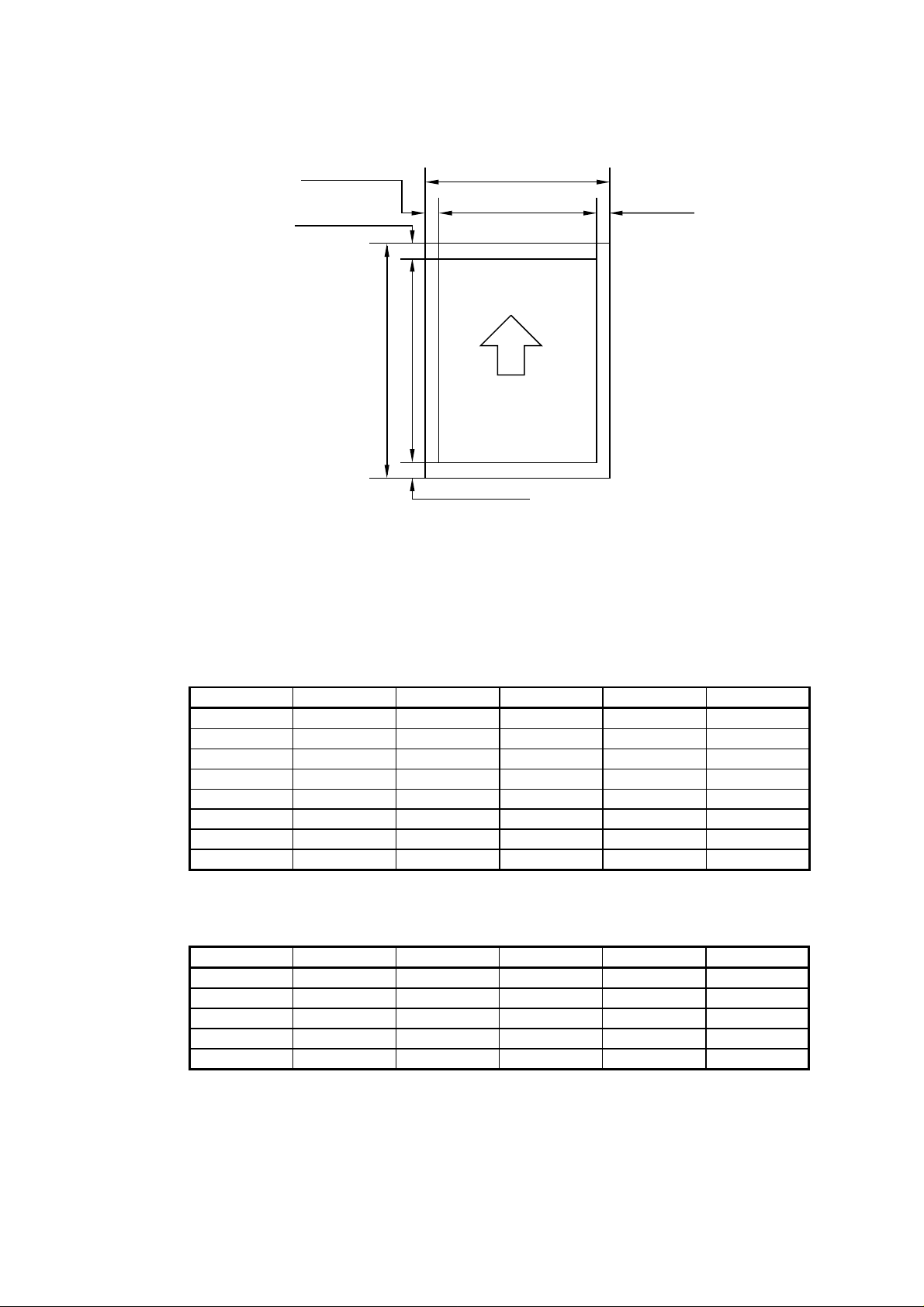
(13) Effective printing area
EA
E
D
B
C
Printable area
E
E
Figure 1.1 Printable Area
Effective printable area is referred to as a area within which is guaranteed the printing of
all interface signal data on a hard copy without any omission.
The tables below shows the effective printable area for each paper size.
Table 1.1 Plain Paper
SIZE A (mm) B (mm) C (mm) D (mm) E (mm)
A4 210.0 297.0 203.2 288.5
Letter 215.9 279.4 207.4 270.9
Legal 215.9 355.6 207.4 347.1
B5 (ISO) 176.0 250.0 167.5 241.5
Executive 184.2 266.7 175.7 258.2
A5 148.0 210.0 139.5 201.5
B6(ISO) 125.0 176.0 116.5 167.5
A6 105.0 148.0 96.5 139.5
Table 1.2 Envelope
SIZE A (mm) B (mm) C (mm) D (mm) E (mm)
COM-10 104.8 241.3 96.3 232.8
MONARCH 98.4 190.5 89.9 182.0
DL 110.1 221.0 101.6 212.5
C5 162.2 228.6 154.1 220.1
B5 (ISO) 176.0 250.0 167.5 241.5
(The sizes above are nominal sizes according to ISO.)
An A4 sheet accepts 80 PICA-pitch characters (203.2mm).
3.39 ± 1.0
4.23 ± 1.0
4.23 ± 1.0
4.23 ± 1.0
4.23 ± 1.0
4.23 ± 1.0
4.23 ± 1.0
4.23 ± 1.0
4.23 ± 1.0
4.23 ± 1.0
4.23 ± 1.0
4.23 ± 1.0
4.23 ± 1.0
I-3

(14) Standard interfaces Automatic interface selection
• Centronics, Bi-directional parallel
• RS-232C serial
Baud rate : 150, 300,1200, 2400, 4800, 9600
19200, 38400, 57600, 115200bps
Stop bit : 1 bit
Start bit : 1 bit or 2 bits
Data length : 7 bits or 8 bits
Parity : Odd, Even, or None
Protocol : Xon/Xoff or DTR
(15) Emulation Automatic emulation selection
• HP Laser Jet 5 (PCL Level 6)
• EPSON FX-850
• IBM Proprinter XL
• BR-Script level 2 (PostScript language emulation
interpreter)
• HP-GL
(16) CPU MB86832 100MHz (SPARC architecture)
(17) Resident fonts 75 scalable fonts and 12 bitmapped fonts
HP Laser Jet 5, EPSON FX-850, IBM Proprinter XL
Scalable Fonts:
Intellifont Compatible Fonts:
• Albertville, Extrabold
• Antique Oakland, Oblique, Bold
• Brougham, Oblique, Bold,
Bold Oblique
• Cleveland Condensed
• Connecticut
• Guatemala Antique, Italic, Bold,
Bold Italic
• Letter Gothic, Oblique, Bold
• Maryland
• Oklahoma, Oblique, Bold,
Bold Oblique
• PC Brussels Light, Light Italic, Demi,
Demi Italic
• PC Tennessee Roman, Italic, Bold,
Bold Italic
• Utah, Oblique, Bold, Bold Oblique
• Utah Condensed, Oblique, Bold,
Bold Oblique
Bitmapped Fonts (Portrait and Landscape):
• Letter Gothic 16.66 Medium, Italic, Bold, Bold Italic
• OCR-A
• OCR-B
Windows 3.1 Compatible Fonts:
• Tennessee Roman, Italic, Bold,
Bold Italic
• Helsinki, Oblique, Bold, Bold Oblique
• BR Symbol
• W Dingbats
BR-Script Fonts:
• Atlanta Book, Book Oblique, Demi,
Demi Oblique
• Copenhagen Roman, Italic, Bold,
Bold Italic
• Portugal Roman, Italic, Bold, Bold Italic
• Calgary Medium Italic
Brother Original Fonts:
• Bermuda Script
• Germany
• San Diego
• US Roman
I-4

BR-Script Level 2 Mode
Scalable Fonts:
• Atlanta Book, Book Oblique, Demi,
Demi Oblique
• Brussels Light, Light Italic, Demi,
Demi Italic
• Brougham, Oblique, Bold, Bold Oblique
• Helsinki, Oblique, Bold, Bold Oblique
• Helsinki Narrow, Oblique, Bold,
Bold Oblique
• Copenhagen Roman, Italic, Bold,
Bold Italic
• Portugal Roman, Italic, Bold, Bold Italic
• Tennessee Roman, Italic, Bold, Bold Italic
• Calgary Medium Italic
• BR Symbol
• BR Dingbats
(18) RAM 8M bytes (expandable to 72M bytes with SIMMs)
(19) PCMCIA card slots Two slots
Right slot for Type I and II
Left slot for Type I, II and III compatible for flash
memory or HDD cards
(20) Power souse USA and Canada : AC 110 to 120 V, 50/60 HZ
Europe and Australia : AC 220 to 240 V, 50/60 HZ
(21) Power consumption Printing : 500 WH or less
Stand-by : 90 WH or less
Sleep : 25 WH
(22) Noise Printing : 55 dB A or less
Stand-by : 40 dB A or less
(23) Dimensions (W x H x D) With A4 paper cassette:
396 x 400 x 389 mm (15.6 x15.7 x 15.3 inches)
With Letter / Legal paper cassette:
396 x 452 x 389 mm (15.6 x18.8 x 15.3 inches)
(24) Weight Approx. 15 kg (33 Ibs)
(25) Environmental conditions
Operating Temperature 10 ~ 32.5°C
environment Relative humidity 20 ~ 80%RH
Air pressure 71.0 ~ 101.3 kPa
Non-operating Temperature 0 ~ 35°C
environment Relative humidity 10 ~ 80%RH
Storage conditions
• Printer Temperature
Normal (total storage time x 9/10)
0 ~ 35°C
Severe (total storage time x 1/10)
High Low
35°C ~ 60°C -20°C ~ 0°C
Temperature change (within 3 minutes)
High Low
60°C 15°C -20°C 25°C
• Albertville, Extrabold
• Antique Oakland, Oblique, Bold
• Cleveland Condensed
• Connecticut
• Guatemala Antique, Italic, Bold, Bold Italic
• Letter Gothic, Oblique, Bold
• Maryland
• Oklahoma, Oblique, Bold, Bold Oblique
• Utah, Oblique, Bold, Bold Oblique
• Utah Condensed, Oblique, Bold,
Bold Oblique
• Bermuda Script
• Germany
• San Diego
• US Roman
(No condensation allowed)
(0 ~ 2,500 m above sea level)
(No condensation allowed)
I-5

Relative humidity
Normal (total storage time x 9/10)
35 ~ 85%RH
Severe (total storage time x 1/10)
High Low
85 ~ 95%RH 10 ~ 35%RH
Air pressure 71.0 ~ 101.3 kPa
Total storage time 0.5 years
• EP-ED HC cartridge Temperature
Normal (2.45 years max.)
0 ~ 35°C
Severe (0.05 years max.)
High Low
35°C ~ 40°C -20°C ~ 0°C
Temperature change (within 3 minutes)
High Low
40°C 15°C -20°C 25°C
Relative humidity
Normal (2.45 years max.)
35 ~ 85%RH
Severe (0.05 years max.)
High Low
85 ~ 95%RH 10 ~ 35%RH
Air pressure 71.0 ~ 101.3 kPa
Maximum total storage time:
2.5 years including used time
3. SAFETY INFORMATION
3.1 Laser Safety (110 ~ 120V Model only)
This printer is certified as a Class 1 laser product under the US Department of Health and
Human Services (DHHS) Radiation Performance Standard according to the Radiation
Control for Health and Safety Act of 1968. This means that the printer does not produce
hazardous laser radiation,
Since radiation emitted inside the printer is completely confined within the protective
housings and external covers, the laser beam cannot escape from the machine during
any phase of user operation.
I-6
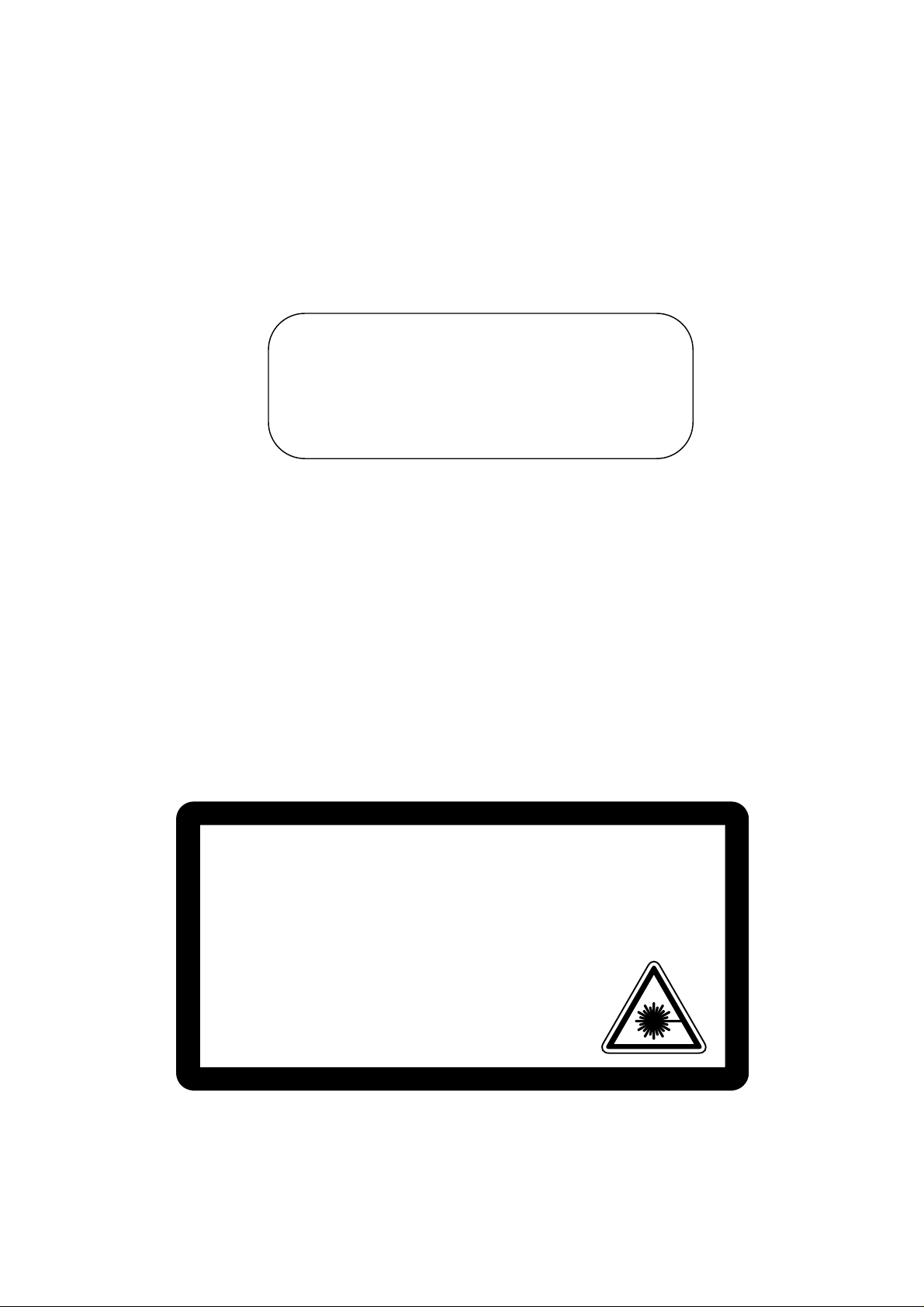
3.2 CDRH Regulations (110 ~ 120V Model only)
The center for Devices and Radiological Health (CDRH) of the US Food and Drug
Administration implemented regulations for laser products on August 2, 1976. These
regulations apply to laser products manufactured from August 1, 1976. Compliance is
mandatory for products marketed in the United States. The label shown below indicates
compliance with the CDRH regulations and must be attached to laser products marketed
in the United States.
MANUFACTURED :
BROTHER INDUSTRIES, LTD.
15-1, Naeshiro-cho, Mizuho-ku Nagoya 467, Japan.
This product complies with FDA radiation
performance standards , 21 CFR chapter 1
subchapter J.
Figure 1.2
Caution: Use of controls, adjustments or performance of procedures other than those
specified in this manual may result in hazardous radiation exposure.
3.3 Additional Information
When servicing or adjusting the optical system of the printer, be careful not to place
screwdrivers or other reflective objects in the path of the laser beam. Be sure to take off
any personal accessories such as watches and rings before working on the printer.
A reflected beam, though invisible, can permanently damage the eyes.
Since the beam is invisible, the following label is attached to the inside of covers where
danger of exposure to laser radiation exist.
INVISIBLE LASER RADIATION WHEN OPEN AND INTERLOCK DEFEATED. AVOID DIRECT EXPOSURE TO BEAM.
CAUTION-
CLASS 38 LASER PRODUCT.
USYNLIG LASER STRÅLING NÅR KABINETLÅGET STÅR ÅBENT. UNGDÅ DIREKTE UDSÆTTELSE FOR STRÅLING.
ADVARSEL-
KLASSE 38 LASER.
OSYNLIG LASERSTRÅLNING NÄR DENNA DEL ÄR ÖPPNAD OCH SPÄRRAR ÄR URKOPPLADE.
VARNING-
STRÅLEN ÄR FARLIG. KLASS 38 LASER APPARAT.
AVATTAESSA JA SUOJALUKITUS OHITETTAESSA OLET ALTTINA NÄKYMÄTTÖMÄLLE LASERSÄTEILYLLE
VAROI-
ÄLÄ KATSO SÄTEESEEN. LUOKAN 38 LASERLAITE.
USYNLIG LASERSTRÅLING, UNNGÅ DIREKTE KONTAKT MED LASERENHETEN NÅR TOPPDEKSELET ER ÅPENT.
ADVARSEL-
KLASSE 38 LASERPRODUKT.
RADIATIONS LASER INVISIBLES QUAND OUVERT ET VERROUILLAGE ENLEVE.
ATTENTIGM-
EVITER EXPOSITIONS DIRECTES AU FAISCEAU. PRODUIT LASER CLASSE 38.
VORSICHT-
UNSICHTBARE LASERSTRAHLUNG WENN ABDECKUNG GEÖFFNET UND
SICHERHEITSVERRIEGELUNG ÜBERBRÜCKT. NICHT DEM STRAHL AUSSETZEN.
SICHERHEITSKLASSE 38.
RADIACIÓN LASER INVISIBLE CUANDO SE ABRE LA TAPA Y EL INTERRUPTOR
ATTENCIÓN-
INTERNO ESTÅ ATASCADO. EVITE LA EXPOSICIÓN DIRECTA DE LOS OJOS.
PRODUCTO LASER CLASE 38.
Figure 1.3
I-7
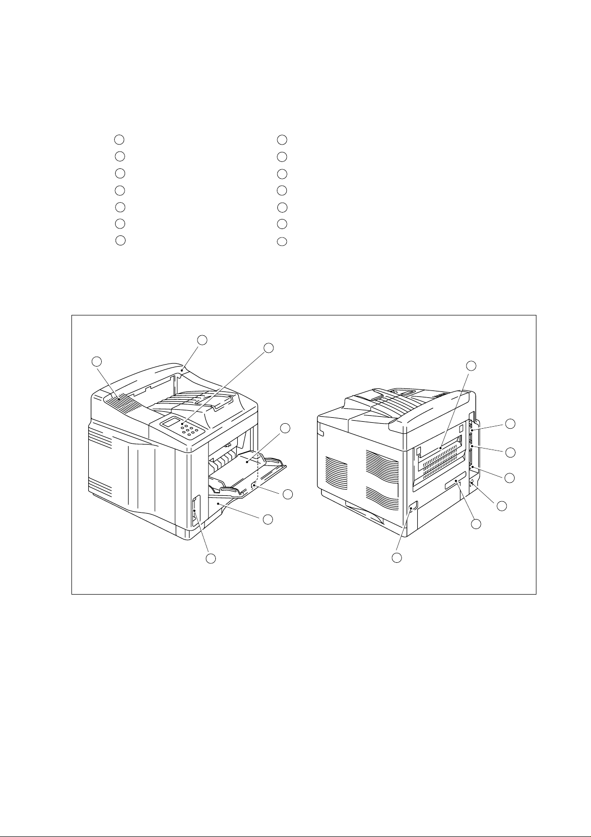
4. PARTS OF THE PRINTER
4.1 External Views
1
Upper cover
2
Control panel
3
MP tray
Tray 1
4
5
Power switch
6
PCMCIA card slots
7
Fan outlet port
1
7
8
Face-up print delivery port
9
Centronics interface connector
RS-232C interface connector
10
11
USB port
12
Duplex unit, Lower tray unit connector
13
Rating label
AC inlet
14
2
8
3
9
10
11
5
12
4
6
14
13
Figure 1.4
I-8

4.2 Cross Sectional View
14
13
12
6
2
1
3
4
5
7
8
11
1
Control panel
2
EP-ED HC cartridge
3
Photosensitive drum
Laser unit
4
5
Transfer unit
6
Face-down tray
7
Print-delivery path
8
Fixing unit
10
9
Low-voltage power supply assy
High-voltage power supply assy
10
11
Paper cassette (Tray 1)
12
Pick-up rollers
13
MP tray
Registration rollers
14
9
Figure 1.5
I-9

5. STORAGE AND HANDLING OF EP-ED HC CARTRIDGES
An EP-ED HC cartridge is influenced by the storage conditions even if it is sealed in its
package, so its life depends on the way in which it is used or stored. EP-ED HC
cartridges should be handled carefully.
5.1 Storage of Sealed EP-ED HC Cartridges
When storing sealed EP-ED HC cartridges in a warehouse or workshop, the storage
conditions shown in (25) Environmental conditions on Page 1-5 must be met. Follow the
instructions below:
1) Avoid direct sunlight.
2) Do not store cartridges on a surface that is subject to vibration.
3) Do not hit or drop the packages containing cartridges.
4) The cartridges should be stored horizontal when they are removed from the body
(with their label side upside).
5) Avoid putting the cartridges near a CRT screen, a disk or a floppy disk (to keep their
data from being destroyed).
5.2 Storage of Unsealed EP-ED HC Cartridges
Each EP-ED HC cartridge contains a photosensitive drum that has an organic
photoconductor (OPC) which deteriorates when exposed to strong light. It also contains
toner. The user, therefore, should be fully informed about the correct storage and
handling of EP-ED HC cartridges.
(1)Storage requirements
1) Avoid places exposed to direct sunlight or near a window. Do not leave an EP-ED
HC cartridge in a car in warm or hot weather even if it is in its storage box.
2) Avoid places with a too-high or too-cool temperature and/or humidity. Also avoid
places exposed to sudden temperature or humidity changes (such as near an air
conditioner outlet).
3) Avoid dusty places or places exposed to ammonia fumes or other harmful fumes.
4) Do not store an EP-ED HC cartridge in a temperature above 40°C.
(2)EP-ED HC cartridge life
The effective life of an EP-ED HC cartridge is 2.5 years from the date of manufacture
(printed on the cartridge.) The expiry year and month (date of manufacture plus 2.5
years) is shown on the EP-ED HC cartridge box. An EP-ED HC cartridge used after
the expiry may produce low-quality printing, so a cartridge should be used within the
stated period.
I-10

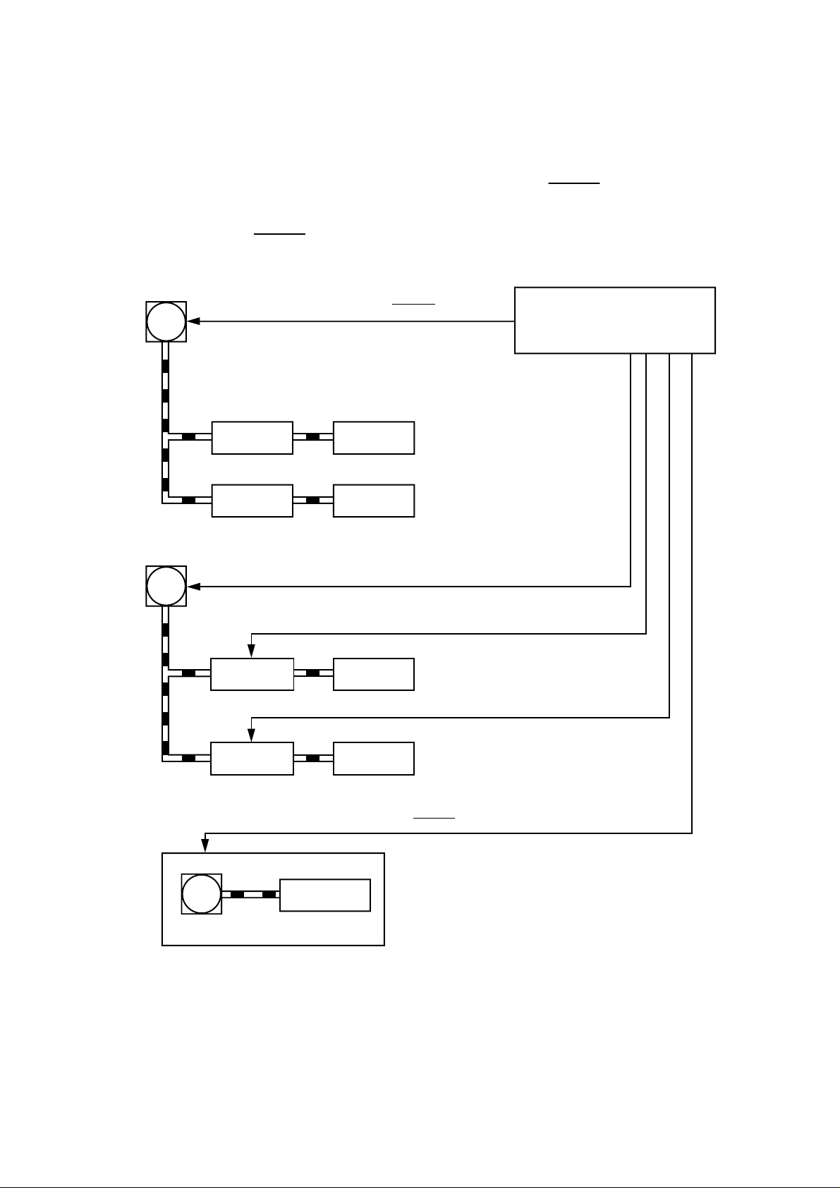
CHAPTER II THEORY OF OPERATION
This chapter describes the printer functions, the relationship between the electrical
systems and mechanical systems, and the timing of operations.
Striped conduits (
appearing with a signal name indicate the transmission of single control signals and
outlined thick arrows (
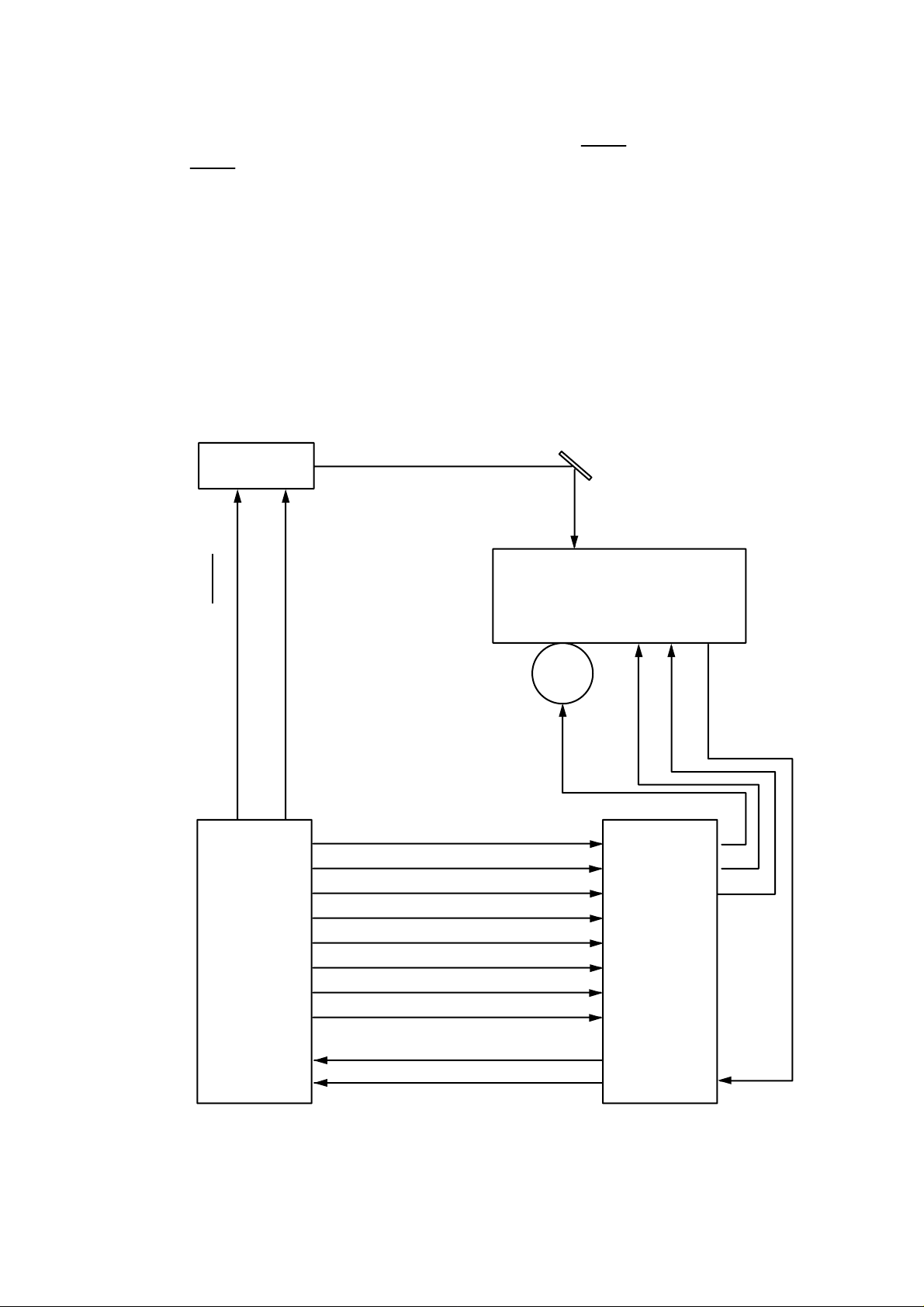
1. BASIC OPERATIONS
1.1 Mechanical Configuration
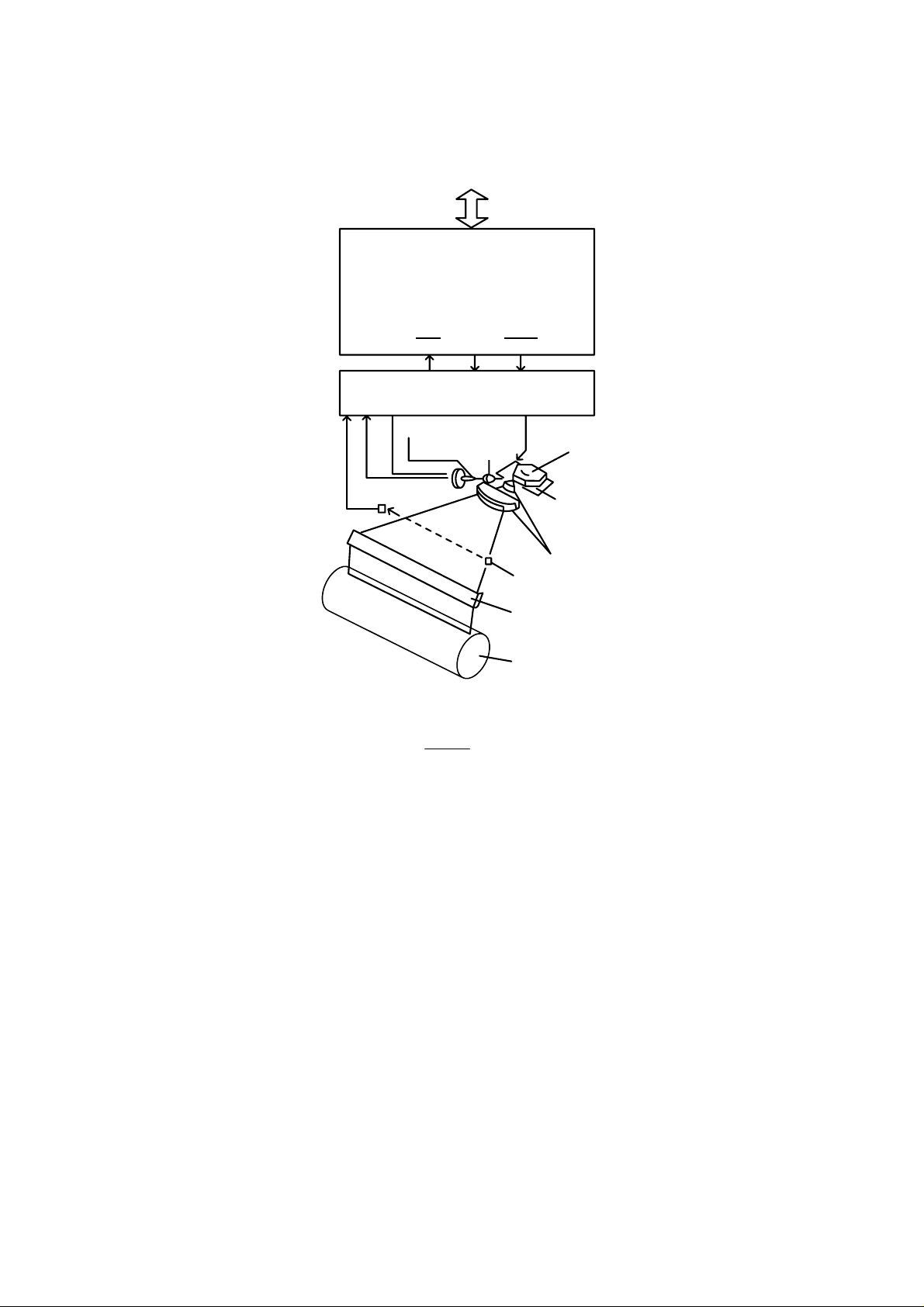
The printer functions can be divided into four blocks: the laser system, the image
formation system, the paper pick-up/feed system and the control system.
) indicate mechanical linkages; solid thin arrows ( )
) indicate the transmission of groups of signals.
Expansion memory
(SIMM)
Control panel
Font card
(2 slots)
Main PCB
IMAGE FORMATION SYSTEM
Photosensitive drum
Cleaning unit
Optional I/O
(MIO)
External Device
CONTROL SYSTEM
Laser unit
Developing
unit
LASER SYSTEM
Delivery rollers
PAPER PICK-UP/FEED SYSTEM
Fixing unit
Feeder
Figure 2.1
Transfer
separation
unit
MP tray
Tray 1
Tray 2
(Option)
II-1
1.2 Main Drive
The power necessary for driving the printer is supplied by the main motor, the paper feed
motor and the laser unit motor.
The main motor is controlled by the main motor drive signal (MDRIVE) output from the
main PCB, and the paper feed motor is controlled by the paper feed motor drive signal
output from the main PCB, and the laser unit motor is controlled by the laser unit motor
drive signal (SDRIVE) output from the main PCB.
Main motor
Main motor drive signal (MDRIVE)
Main PCB
Paper feed motor
Drum gear
Fixing unit
Paper feed motor drive signal
MP tray pick-up roller solenoid drive signal (MPSOL)
MP tray pick-up
roller solenoid
Tray1 pick-up roller solenoid drive signal (PUCL1)
Tray1 pick-up
roller solenoid
Laser unit motor drive signal (SDRIVE)
Photosensitive
drum
Paper delivery
rollers
MP tray
pick-up roller
Tray1
pick-up roller
Laser unit motor
Laser unit
Scanning mirror
Note: There are cases, in the following pages,
that a main motor is referred to as a DC
motor, but they are identical.
Figure 2.2
II-2

1.3 Basic Sequence of Operations
Timing for two consecutive prints on A4 paper.
Power on Print
Ready lamp
Fixing heater
Main motor
Laser unit motor
Paper feed
motor
Pick-up roller
solenoid
WAIT STBY PRINT
180 C control 210 C
0.18 sec
0.12 sec
1.50 sec
1.38 sec
control
STBY
180 C
control
Laser diode
Registration
sensor
2.54 sec
Figure 2.3
II-3
2. LASER SYSTEM
To external device
Main PCB
SBD DATA VOFF
Laser unit driver
Collimator lens
Cylindrical lens
Optical sensor
Scanning mirror
Laser unit motor
Focusing lenses
Beam detect mirror
Reflective mirror
Photosensitive drum
Figure 2.4
In response to the print signal transmitted from the external device, the main PCB
generates the drive signals (DATA,VOFF) for the laser diode and sends the signals to the
laser unit.
The laser diode in the laser unit generates a laser beam modulated by DATA.
The modulated laser beam is aligned into a parallel beam by a collimator lens and a
cylindrical lens and then brought to the scanning mirror which is rotating at a constant
speed.
The laser beam reflected by the scanning mirror focuses on the photosensitive drum via
the focusing lenses arranged in front of the scanning mirror.
The path of the beam coming through the focusing lenses is reflected by the reflective
mirror.
As the scanning mirror rotates at a constant speed, the laser beam scans the
photosensitive drum at a constant speed.
As the photosensitive drum rotates at a constant speed and the laser beam scans the
drum, an images is formed on the drum.
II-4
3. IMAGE FORMATION SYSTEM
3.1 Outline
The image formation system is the main part of the printer. The print information, after
input from the video controller circuit into the engine controller circuit as a TVDO signal,
forms a toner image on the photosensitive drum.
Then the toner image is transferred onto the paper by the transfer charging roller. The
image formation system is composed of the photosensitive drum the charging unit, the
developing unit and the cleaning unit.
3.2 Printing Process
The major part of the image formation system is contained in the cartridge, as shown in
Figure 2.5.
Cartridge
Primary charging roller
Cleaning blade
Photosensitive drum
Static charge eliminator
Laser beam
Blade
Developing cylinder
Paper
Transfer charging roller
Figure 2.5
The cartridge used by the printer has a seamless photosensitive drum with the structure
shown in Figure 2.6. The outer layer of the drum consists of an organic photoconductor
(OPC); the base is aluminum.
The printing process can be divided into five major stages:
Photoconductive layer
Base
Figure 2.6
1. Electrostatic latent image formation stage
Step 1 Primary charge (-)
Step 2 Scanning exposure
2. Developing stage
Step 3 Development
II-5

3. Transfer stage
Step 4 Transfer (+)
Step 5 Separation
4. Fixing stage
Step 6 Fixing
5. Drum cleaning stage
Step 7 Drum cleaning
Electrostatic latent image
formation stage
2. Scanning exposure
1. Primary charge
6. Fixing
7. Drum cleaning
5. Separa tion
4. Transfer
Transfer stage
Drum cleaning stage
Fixing stage
Print delivery
Figure 2.7
3.2.1 Electrostatic latent image formation stage
This stage has two steps, which together produce a pattern of electrical charges on the
photosensitive drum.
At the end of the stage, negative charges remain in the unexposed “dark” area. Charges
are absent from the “light” areas, where the laser beam struck (exposed) the drum
surface.
Since this image of negative charges on the drum is invisible to the eye, it is called an
“electrostatic latent image”.
3. Develop
ment
Cassette feed
Developing stage
Registration
Paper path
Direction of drum rotation
Multi-purpose tray feed
0
-100
-500
Primary
Surface potential (V)
charge
(step 1)
Exposed
area
Scanning
exposure
(step 2)
Figure 2.8
II-6
Unexposed
area
Transfer
(step 4)
Time (t)
Primary
charge
(step 1)
Step 1 Primary charge
,,
,
,
,,
,,
,
,
,
,,
,,
,,
,
,
,,
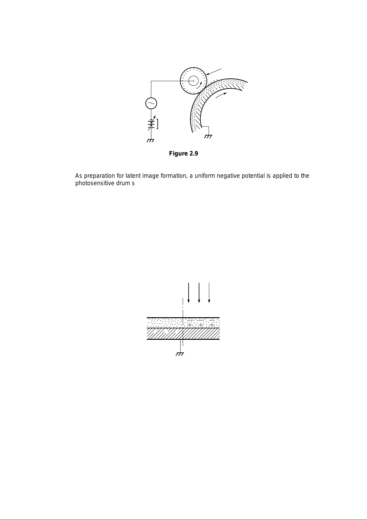
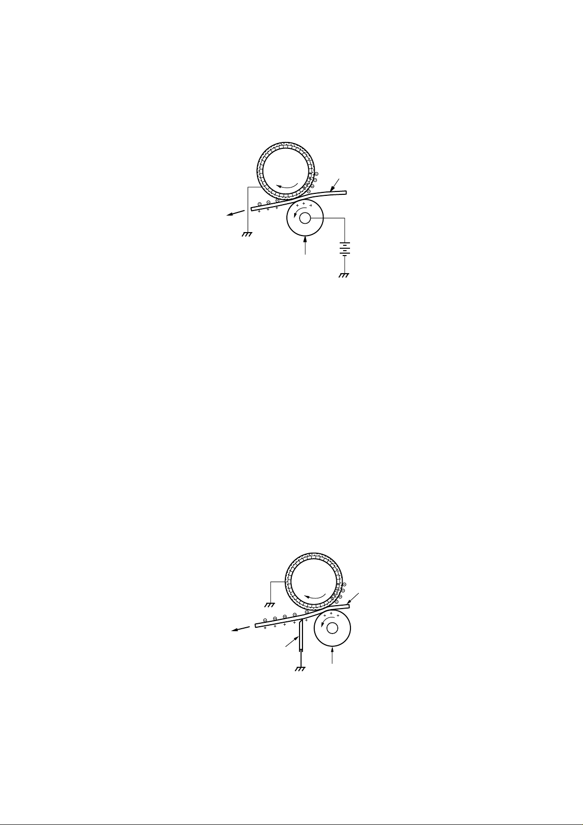
As preparation for latent image formation, a uniform negative potential is applied to the
photosensitive drum surface. The printer uses the charging method that directly charges
the drum for the primary charge.
The primary charging roller consists of conductive rubber. In addition to DC bias, AC bias
is applied to the primary charging roller to keep the potential on the drum surface uniform.
This DC bias is changed with the developing DC bias.
This charging method has advantages such as lower applied voltage, less ozone
generation, etc., compared with the corona charge system.
Primary charging roller
AC bias
Photosensitive drum
DC bias
Figure 2.9
Step 2 Scanning exposure
When the laser beam scans the drum surface, it causes the charge to be neutralized in
the areas struck by the beam. Areas on the drum with no charge form the electrostatic
latent image.
Laser beam
___
+++
Unexposed area Exposed area
Figure 2.10
II-7
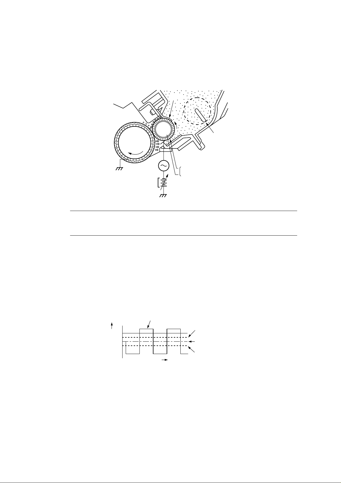
3.2.2 Developing stage
Development places particles of toner onto the areas of the drum that have been cleared
of charge by the laser beam. This makes a visible image. This printer uses the toner
projection development method with a single-component toner.
Step 3 Development
Blade
Photo-
sensitive
drum
AC bias
DC bias
Developing cylinder
Cylinder
Magnet
Stirrer
Figure 2.11
Note: The charges on the light areas on the photosensitive drum are shown as positive
in this figure. Actually they are negative, but they are more positive than the
developing cylinder and explanation is simplified by regarding them as positive.
As shown in Figure 2.11, the developing unit consists of a developing cylinder and rubber
blade. The developing cylinder rotates around a fixed internal magnet. The singlecomponent toner consists of magnetite and a resin binder, and is held to the cylinder by
magnetic attraction. The toner is an insulator, and acquires a negative charge by friction
due to the rotation of the cylinder.
The areas on the drum that were exposed to the laser beam have a higher potential (are
less negative) than the negatively charged toner particles on the developing cylinder.
When these areas approach the cylinder, the potential difference projects the toner
particles onto them. This is called toner projection, and the latent image on the drum
becomes visible.
Developing cylinder
surface potential
+V
0
Drum surface
potential
(exposed area)
DC bias
-V
Voltage (V)
Time t
Drum surface
potential
(unexposed area)
Figure 2.12
An AC bias is applied to the developing cylinder to help project the toner particles to the
drum surface and improve the contrast of the printed image. The center voltage of the AC
bias (1600 Vp-p) varies with the DC bias voltage.
The IMAGE DENSITY ADJUSTMENT signal (sent from the Engine CPU to the highvoltage power supply) changes the DC bias, and thus the potential difference between
the cylinder and drum. This changes the density of the print.
This printer has a stirring mechanism to supply toner in the cartridge smoothly to the
cylinder.
II-8
3.2.3 Transfer stage
In the transfer stage, the toner image is transferred from the drum surface to the paper.
Step 4 Transfer
A positive charge applied to the back of the paper attracts the negatively charged toner
particles to the paper. The printer accomplishes transfer by using the charging roller
method. Advantages compared with the corona transfer method are as follows:
• Low transfer voltage that is less than half that for corona transfer.
• Less ozone generation.
• The paper is supported by the transfer charging roller and photosensitive drum, so
feed is more stable.
Photo-
sensitive
drum
Transfer charging roller
Figure 2.13
Paper
Reference:
If the image on the photosensitive drum is not completely transferred to the paper due to
jamming, etc., the toner may adhere to the transfer charging roller. The printer removes
the toner from the transfer charging roller by switching the transfer voltage between
positive and negative in sequence. During wait, initial rotation, and last rotation, the
printer sets the primary DC voltage to zero, and sets the charge on the drum to zero. In
this case, the transfer voltage is made negative to remove the negatively-charged toner
on the transfer charging roller to the drum. The transfer charging roller is thus cleaned.
Step 5 Separation
Static charge
eliminator
Figure 2.14
Photo-
sensitive
drum
Transfer charging roller
Paper
The stiffness of the paper causes it to separate from the drum. (Curvature separation)
To stabilize the paper feed and prevent small white circles from appearing in the printed
image at low temperature and humidity, the charge on the back of the paper is reduced
by the static charge eliminator after transfer.
II-9

3.2.4 Fixing stage
The toner image transferred to the paper in the transfer stage is held only by electrostatic
attraction and slight physical adhesion, so even a light touch will smear the image.
In the fixing stage, the toner image is fixed by heating the paper and applying pressure.
This fuses the toner particles to the paper to make a permanent image.
Step 6 Fixing
Halogen heater
Upper fixing roller
Toner
Paper
Lower fixing roller
Figure 2.15
The upper roller surface is PFA-coated. The upper and lower roller surfaces are
grounded via a diode to prevent the negative potential of the upper roller becoming higher
than that of the lower roller, resulting in the toner being drawn to the lower roller, and
adhering to the lower roller surface.
3.2.5 Drum cleaning stage
In the transfer stage, not all the toner is transferred to the paper. Some remains on the
photosensitive drum. This residual toner is cleaned off in the drum cleaning stage so that
the next print image will be clear.
Step 7 Drum cleaning
Cleaning blade
Photo-
sensitive
drum
Sweeper stripCleaner container
Figure 2.16
Prior to the next printing, the residual toner on the drum surface is scraped away by the
cleaning blade to clean the drum surface. The removed toner is collected in the cleaner
container.
II-10
3.3 Operation
When the engine controller circuit receives a print signal (PRINT) or a pre-feed signal
(PRFD) from the video controller circuit, the engine controller circuit drives the main
motor to rotate the photosensitive drum.
After the drum surface is charged negatively by the primary charge roller, the laser beam
modulated by a DATA signal scans the drum surface to from a latent image on the drum.
The latent image formed on the drum surface is converted into a visible image by the
toner on the developing cylinder and then image is transferred onto the paper by the
transfer roller unit. Then the residual toner is removed from the drum surface with the
cleaner blade.
The cartridge also has a toner sensor. When the output from this sensor falls below a
certain level, it warns that the EP-ED HC cartridge will be out of toner with an alarm.
Laser unit
Reflection mirror
Laser beam
Laser diode drive signal (DATA)
Scanner motor drive signal (SDRIVE)
Primary charge (AC) drive (HV1AC)
Main
PCB
Primary charge (DC) drive (HV1DC)
Developing bias (AC) drive (DBAC)
Developing bias (DC) drive (DBDC)
Transfer charger 1 drive (HVT1)
Transfer charger 2 drive (HVT2)
Transfer charger 3 drive (HVT3)
Transfer charger 4 drive (HVT4)
EP-ED HC cartridge
Transfer
roller
High-voltage
power supply
PCB
Toner sensor signal 1 (TONER 1)
Toner sensor signal 2 (TONER 2)
Figure 2.17
II-11
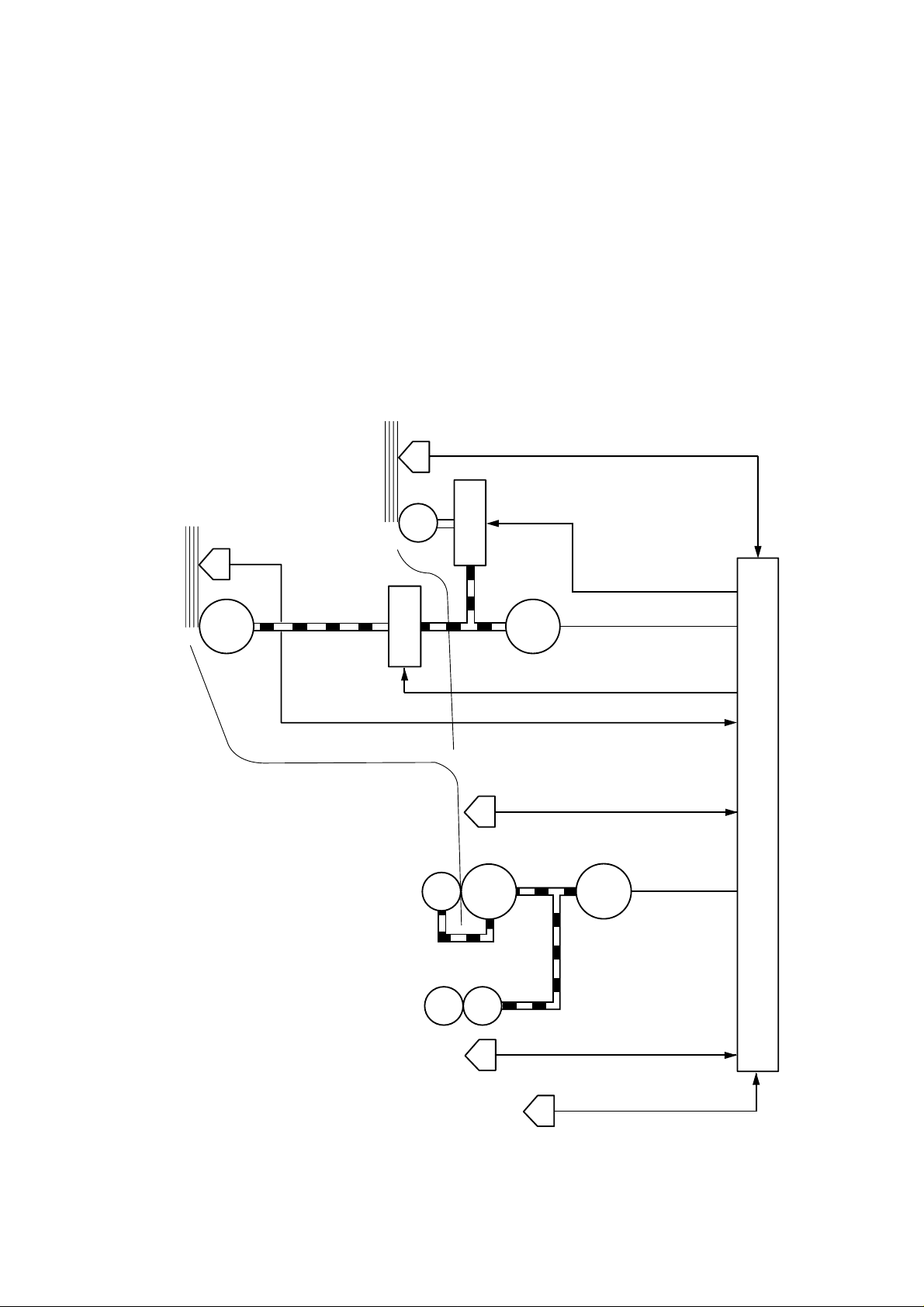
4. PAPER PICK-UP/FEED SYSTEM
4.1 Outline
If a tray1 paper pick-up roller solenoid drive signal (PUCL1) is input to the circuit while the
paper feed motor is rotating, the paper pick-up solenoid comes on and the paper pick-up
roller solenoid is engaged. As a result, the paper pick-up roller rotates to feed paper
down to the photosensitive drum.
The paper position is controlled by the registration sensor so that the leading edge of the
paper is aligned with the leading edge of the image on the photosensitive drum. After this
operation, the paper is deliveried to the face down tray via the fixing unit. Paper ejection
is detected by the paper ejection sensor; if printed paper has not reached or not cleared
the paper ejection sensor in a specified time, the printer judges that a paper jam has
occurred. In this case a paper jam is noticed to the external devise by a status signal.
MP tray
paper empty sensor
Tray paper
empty sensor
MP tray paper empty sensor signal (PEMP)
MP tray Pick-up
roller solenoid
MP tray pick-up roller
solenoid drive signal (MPSOL)
Paper feed motor drive signal
Tray1 Pick-up
roller solenoid
Transfer roller
Fixing rollers
Paper-
feed
motor
Tray1 pick-up roller solenoid drive signal (PUCL1)
Tray1 paper empty sensor signal (PETRAY1)
Registration sensor signal (REGIST)
Registration
sensor
drum
Photosensitive
Paper ejection sensor signal (EJECT)
Main motor drive
signal (MDRIVE)
Main motor
Main PCB
Paper ejection sensor
Figure 2.18
II-12
Stuck-full sensor
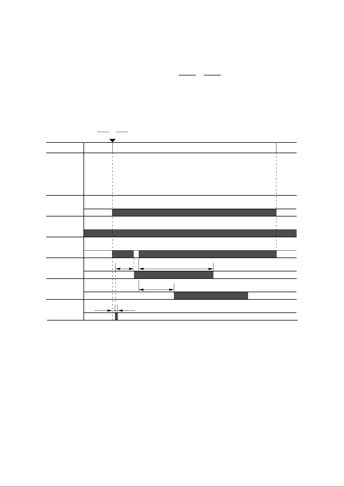
4.2 Cassette Feed
When the fixing rollers reach the specified temperature while a cassette with paper is in
the printer, the READY lamp changes from flashing to lighting.
When the engine controller circuit receives PRNT or PRFD signal from the video
controller circuit, the paper feed motor starts rotation. About 0.2 seconds later, the printer
actuates the tray1 pick-up roller solenoid and the pick-up roller makes one rotation.
This feeds paper to the photosensitive drum.
Timing chart for the pick-up one sheet
PRNT or PRFD
STBY PRINT STBY
Main motor
Paper empty
sensor
Paper feed
motor
Registration
sensor
Paper ejection
sensor
Pick-up roller
solenoid
0.12 sec
1.38 sec 2.54 sec
1.74 sec
0.12 sec
Figure 2.19
II-13
 Loading...