

Page 1
Home Sewing Machine
SERVICE MANUAL
MODEL :
J14/LS14/LX-1400/X14/L14/STAR1400
JS1400/JS1410/J17/LS17/LX-1700
X17/L17/JS1700/AS1430S/JSL15/JSL18/LS200
LS300/artwork19/artwork22/SL10/HQ18/X7/JX1410
JX1710/JX2517/AS1450/RS100/RS200/JX1400
JS1420/LS2225/LS2325/SL100/VitrageM71
VitrageM73/ArtCity140/JS1750/NB1400/NB1700
KD144/K14/F14/K17/F17/KE14/ArtCity170
CONFIDENTIAL
c
2012 Brother Industries, Ltd.
All rights reserved.
Published :
Revised :
Aug.,2012
May,2015
Page 2
Page 3

LIST of UPDATE RECORD
Date Added Models Contents
Dec.,2012 JS1700
Feb.,2013 AS1430S
Mar.,2013 X7/artwork19/JSL15/LS200
Mar.,2013 SL10/HQ18/artwork22/JSL18/LS300
Apr.,2013 JX1710/JX2517
May,2013 JX1410
Jul.,2013 AS1450
Sep.,2013 RS100/RS200
Mar.,2014 JX1400
Apr.,2014 JS1420
Jun.,2014
LS2225/LS2325
-
-
-
-
-
-
-
-
-
-
-
Aug.,2014
Feb.,2015
Mar.,2015
Apr.,2015
Apr.,2015
May,2015
SL100
VitrageM71/VitrageM73
ArtCity140
JS1750/NB1400/NB1700
KD144/K14/F14/K17/F17/KE14
ArtCity170
-
-
-
-
-
-
Page 4

1. Outline of Mechanism ........................................................................1 - 1
Main mechanisms ..............................................................................................1 - 2
Driveline .............................................................................................................1 - 3
Positions of electronic components ...................................................................1 - 5
Control system block diagram ...........................................................................1 - 6
2. Basic of Disassembly/Assembly .......................................................2 - 1
Disassembly
Preparation ........................................................................................................2 - 2
Disconnecting cables & Removing accessories .................................................................................2 - 2
Main frame and Covers .....................................................................................2 - 3
Removal of Face plate assy and Front cover assy .............................................................................2 - 4
Removal of Rear cover assy and Base plate L/R ...............................................................................2 - 5
Main motor unit ..................................................................................................2 - 7
Removal of LED lamp assy ...............................................................................................................2 - 8
Removal of Motor 3P supply assy .....................................................................................................2 - 9
Feed unit / Feed control ...................................................................................2 - 10
Removal of Tension pulley assy and Lower shaft B assy ...............................................................2 - 11
Removal of Feed module .................................................................................................................2 - 12
Removal of Feed connecting lever assy ..........................................................................................2 - 13
Needle threading mechanism ..........................................................................2 - 14
Removal of Thread tension dial assembly .......................................................................................2 - 15
Pattern selecting mechanism ...........................................................................2 - 16
Removal of Pattern selecting unit assy ............................................................................................2 - 17
Bobbin winder, Upper shaft, Needle-presser module ......................................2 - 18
Removal of Bobbin winder assy ......................................................................................................2 - 19
Removal of Upper shaft assy ...........................................................................................................2 - 20
Removal of Needle-presser module .................................................................................................2 - 21
Assembly
Bobbin winder, Upper shaft, Needle-presser module ......................................2 - 23
Attachment of Needle-presser module ............................................................................................2 - 24
Attachment of Upper shaft assy .......................................................................................................2 - 26
Attachment of Bobbin winder assy ..................................................................................................2 - 27
Pattern selecting mechanism ...........................................................................2 - 28
Lubrication .......................................................................................................................................2 - 29
Attachment of Pattern selecting unit assy ........................................................................................2 - 30
Needle threading mechanism ..........................................................................2 - 32
Attachment of Thread tension dial assembly ...................................................................................2 - 33
Feed unit / Feed control ...................................................................................2 - 34
Lubrication .......................................................................................................................................2 - 35
Attachment of Feed connecting lever assy ......................................................................................2 - 36
Attachment of Feed module .............................................................................................................2 - 37
Attachment of Lower shaft B assy and Tension pulley assy ........................................................... 2 - 38
Phase matching of Upper shaft and Lower shaft .............................................................................2 - 39
i
Page 5

Main motor unit ................................................................................................2 - 40
Attachment of Motor 3P supply assy ...............................................................................................2 - 41
Attachment of LED lamp assy .........................................................................................................2 - 42
Main frame and Covers ...................................................................................2 - 43
Attachment of Rear cover assy and Base plate L/R .........................................................................2 - 4 4
Attachment of Face plate assy and Front cover assy .......................................................................2 - 46
3. Application of Disassembly/Assembly .............................................3 - 1
Disassembly
Main frame and Covers .....................................................................................3 - 2
Disassembly of Face plate assy .........................................................................................................3 - 3
Disassembly of Rear cover assy ................................. .......................................................................3 - 4
Disassembly of Base plate L/R ..........................................................................................................3 - 5
Main motor unit ..................................................................................................3 - 6
Disassembly of Motor 3P supply assy ...............................................................................................3 - 7
Feed unit ............................................................................................................3 - 8
Disassembly of Tension pulley assy ..................................................................................................3 - 9
Disassembly of Lower shaft B assy .................................................................................................3 - 10
Disassembly of Feed module ...........................................................................................................3 - 11
Needle threading mechanism ..........................................................................3 - 19
Disassembly of Thread tension dial assembly .................................................................................3 - 20
Pattern selecting mechanism ...........................................................................3 - 21
Disassembly of Pattern selecting unit assy ...................................................................................... 3 - 22
Bobbin winder, Upper shaft, Needle-Presser module ......................................3 - 23
Disassembly of Bobbin winder assy ................................ ................................................................3 - 24
Disassembly of Upper shaft assy ........................................... .......................................................... 3 - 25
Disassembly of Needle-presser module ...........................................................................................3 - 26
Assembly
Bobbin winder, Upper shaft, Needle-Presser module ......................................3 - 30
Lubrication .......................................................................................................................................3 - 31
Assembly of Needle-presser module ...............................................................................................3 - 32
Assembly of Upper shaft assy .........................................................................................................3 - 36
Assembly of Bobbin winder assy ............................ ........................................................................3 - 37
Pattern selecting mechanism ...........................................................................3 - 38
Lubrication .......................................................................................................................................3 - 39
Assembly of Pattern selecting unit assy ..........................................................................................3 - 40
Needle threading mechanism ..........................................................................3 - 41
Assembly of Thread tension dial assembly .....................................................................................3 - 42
Feed unit ..........................................................................................................3 - 43
Lubrication .......................................................................................................................................3 - 44
Assembly of Feed module ...............................................................................................................3 - 45
Assembly of Lower shaft B assy .....................................................................................................3 - 53
Assembly of Tension pulley assy ....................................................................................................3 - 54
Main motor unit ................................................................................................3 - 55
Assembly of Motor 3P supply assy .................................................................................................3 - 56
ii
Page 6

Main frame and Covers ...................................................................................3 - 57
Assembly of Base plate L/R ............................................................................................................3 - 58
Assembly of Rear cover assy ....................... ....................................................................................3 - 59
Assembly of Face plate assy ............................................................................................................3 - 60
4. Adjustment ..........................................................................................4 - 1
Removal of covers .............................................................................................4 - 2
Needle point damage .........................................................................................4 - 4
Timing belt tension .............................................................................................4 - 5
Motor belt tension ..............................................................................................4 - 6
Needle plate holder assy position ......................................................................4 - 7
Presser foot hole / Needle plate hole position (front/back) ................................4 - 8
Needle swing timing ...........................................................................................4 - 9
Three point needle drop ...................................................................................4 - 10
Needle interference left/right ............................................................................4 - 11
Needle bar rising ..............................................................................................4 - 12
Needle bar height ............................................................................................4 - 14
Needle clearance .............................................................................................4 - 15
Left straight stitch needle drop and
zigzag stitch maximum left needle drop position .............................................4 - 16
Feed dog position (front/back and left/right) ....................................................4 - 18
Feed dog height ...............................................................................................4 - 19
Upper thread tension .......................................................................................4 - 20
Left and right stitch of buttonhole stitch length ................................................4 - 22
Bobbin winder ..................................................................................................4 - 25
Lower thread tension .......................................................................................4 - 26
5. Failure Investigation for Electronic Parts .........................................5 - 1
Sewing lamp does not light ................................................................................5 - 2
Main motor does not turn or Rotation speed is slow ..........................................5 - 3
6. Special Instructions of Wiring ...........................................................6 - 1
Motor 3P supply assy ........................................................................................6 - 2
LED lead wire ....................................................................................................6 - 3
iii
Page 7

1
Outline of Mechanism
Main mechanisms..................................................... 1 - 2
Driveline.................................................................... 1 - 3
Positions of electronic components........................... 1 - 5
Control system block diagram................................... 1 - 6
1 - 1
Page 8
Outline of Mechanism
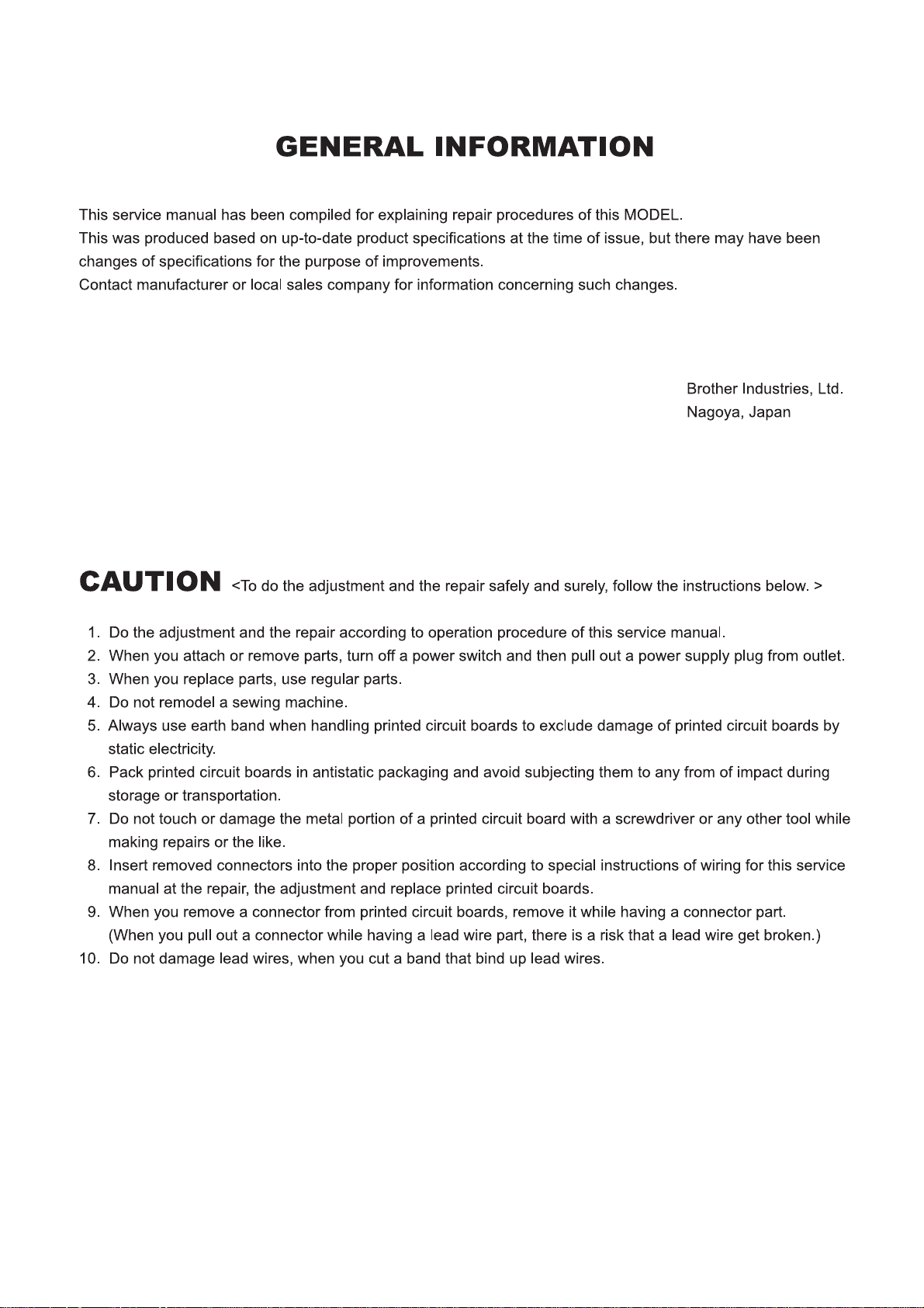
Main mechanisms
Bobbin winder Mechanism
Outline of
Mechanism
Needle bar / Presser foot
Mechanism
Front Side View
Zigzag Mechanism
Lower shaft Mechanism
Thread guide Mechanism
Horizontal feed Mechanism
Feed / Rotary hook Mechanism
Upper shaft Mechanism
Pattern selecting
Mechanism
Outline of
Mechanism
1 - 2
Back Side View
Page 9

Outline of Mechanism
Driveline
(A) Up and down movement of needle bar, movement of thread take-up lever and
zigzag movement of needle bar mechanism
Main motor
Outline of
Mechanism
Needle bar crank
Needle bar
crank rod
Needle bar
block shaft
Needle bar block
Needle bar
Needle
Z finger frame
Thread take-up
counter weight
Needle bar
supporter
Pattern cam
Worm gear
Motor belt
Timing pulley
Upper shaft Pulley
Worm gear
Pattern cam
Z finger frame
Zigzag
connecting rod
Timing pulley
Selecting cam
Pulley
Outline of
Mechanism
A
Thread take-up counter weight
Needle bar crank rod
Needle bar block
Needle bar
supporter
Needle
Upper shaft
Needle bar crank
Needle bar block shaft
Zigzag connecting rod
Needle bar
1 - 3
Selecting cam
A
Motor belt
Main motor
Page 10

Outline of Mechanism
Driveline
(B) Movement of feed dog and rotary hook
Main motor
Motor belt
Outline of
Mechanism
Lower shaft gear
Outer rotary
hook assy
Vertical lever
Vertical adjuster screw
Feed stand spring cap
Feed cam
Feed arm B
Feed arm A
Feed stand
Feed dog
Timing pulley DLower shaft
Feed adjuster
Timing belt
Feed connecting
lever
Upper shaft pulley
Upper shaft
pulley
Feed regulator plate
A / B
Timing pulley
Timing pulley
Upper shaft
Selecting cam
Pulley
Pattern selecting dial
Pulley
Outline of
Mechanism
Feed stand spring cap
Vertical lever
Feed dog
Feed stand
Lower shaft gear
Upper shaft
Feed cam
Feed connecting lever
Vertical adjuster screw
Feed adjuster
Feed arm A
Outer rotary hook assy
Selecting cam
Pattern selecting dial
Feed regulator plate A / B
Feed arm B
V feed attachment
Timing belt
Motor belt
Timing pulley D
Main motor
Lower shaft
1 - 4
Page 11
Outline of Mechanism
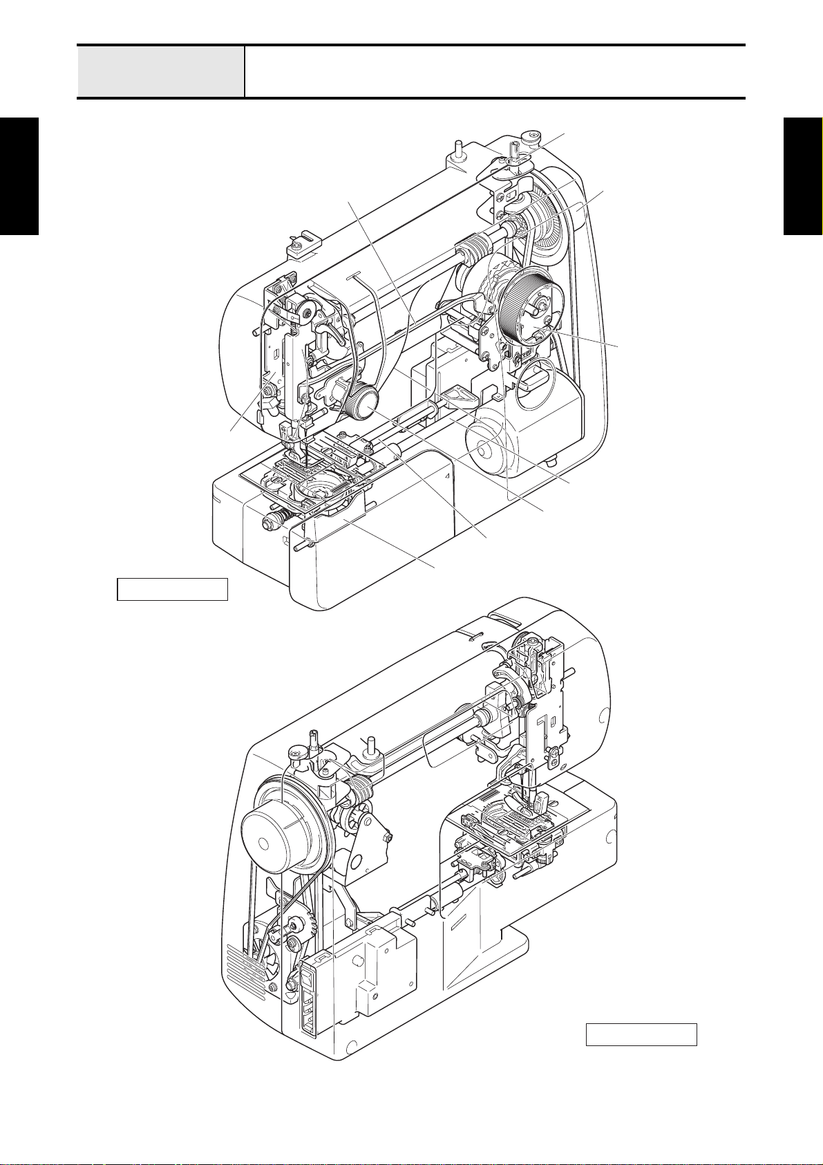
Positions of electronic components
Outline of
Mechanism
Power supply PCB
Sewing lamp (LED)
3pin socket
Power SW
Main motor
Outline of
Mechanism
1 - 5
Page 12
Outline of Mechanism
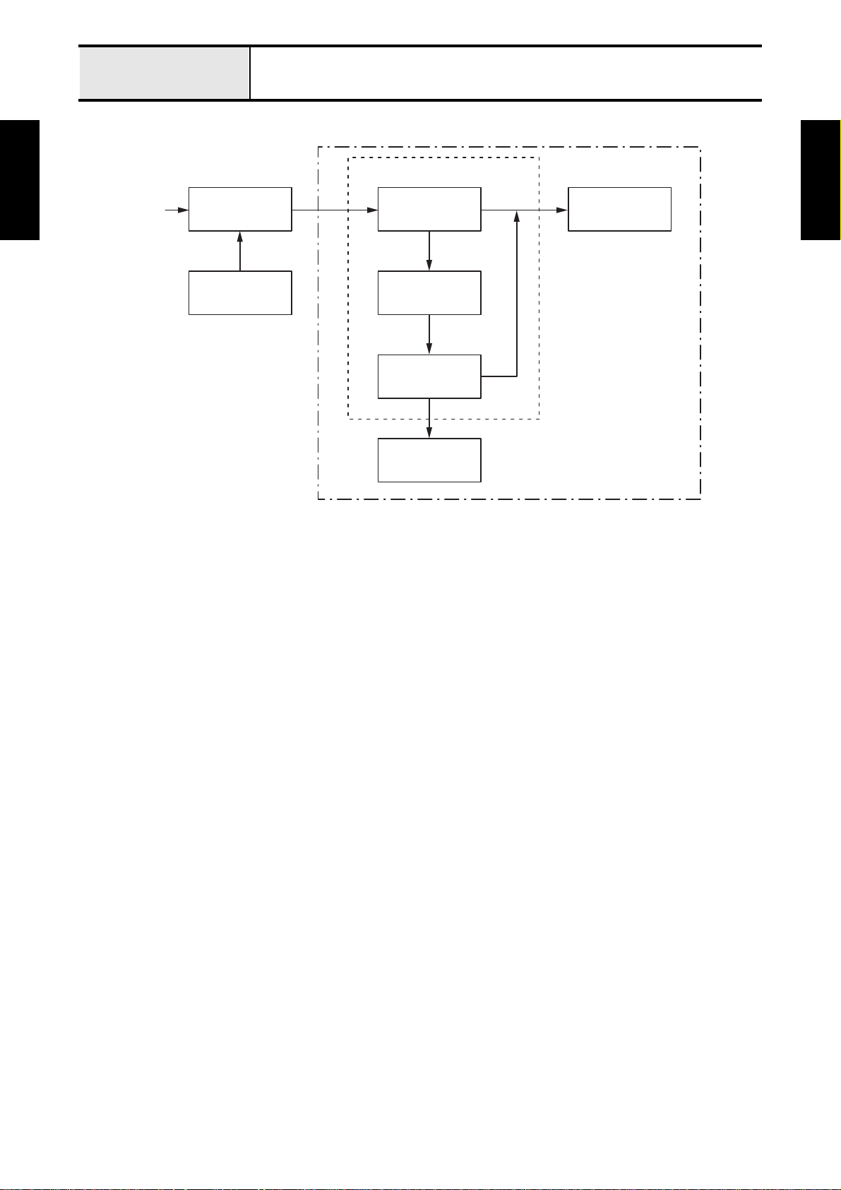
Control system block diagram
In the 3pin socket
Outline of
Mechanism
AC
Foot controller plug
(3pin)
Foot controller
3pin socket
Power SW
Power supply PCB
Sewing lamp
(LED)
Main motor
SEWING MACHINE
Outline of
Mechanism
1 - 6
Page 13

Basic of
2
Disassembly/Assembly
When repair and replace the part of the unit, refer to
“CHAPTER 3: Application of Disassembly/Assembly”.
Disassembly Preparation...................................... 2 - 2
Main frame and Covers................... 2 - 3
Main motor unit................................ 2 - 7
Feed unit / Feed control................. 2 - 10
Needle threading mechanism........ 2 - 14
Pattern selecting mechanism ........ 2 - 16
Bobbin winder, Upper shaft,
Needle-presser module................. 2 - 18
Assembly Bobbin winder, Upper shaft,
Needle-presser module................. 2 - 23
Pattern selecting mechanism ........ 2 - 28
Needle threading mechanism........ 2 - 32
Feed unit / Feed control................. 2 - 34
Main motor unit.............................. 2 - 40
Main frame and Covers................. 2 - 43
2 - 1
Page 14
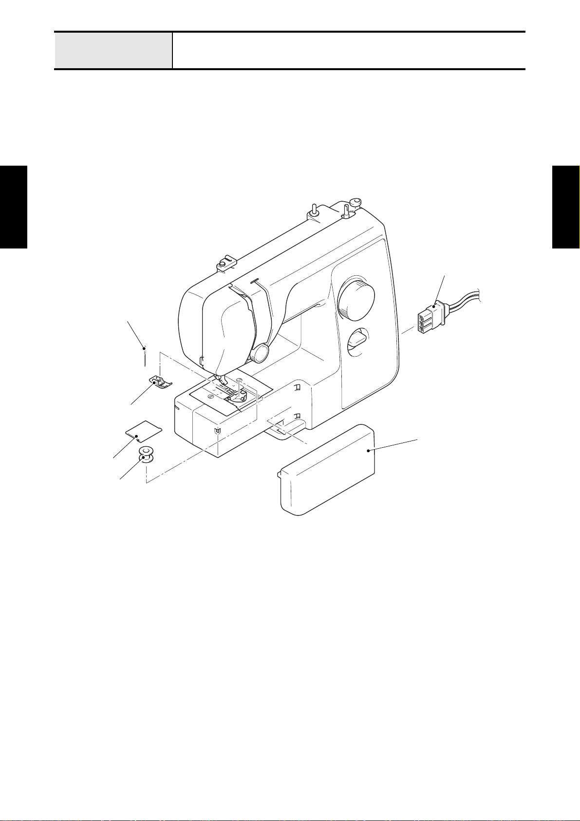
Basic of Disassembly
Preparation
1 Disconnecting cables & Removing accessories
• Foot controller socket
• Needle
• Presser foot
• Accessory table
• Slide plate
• Bobbin
Basic of
Disassembly
Basic of
Disassembly
Foot controller socket
Needle
Presser foot
Accessory table
Slide plate
Bobbin
2 - 2
Page 15
Basic of Disassembly
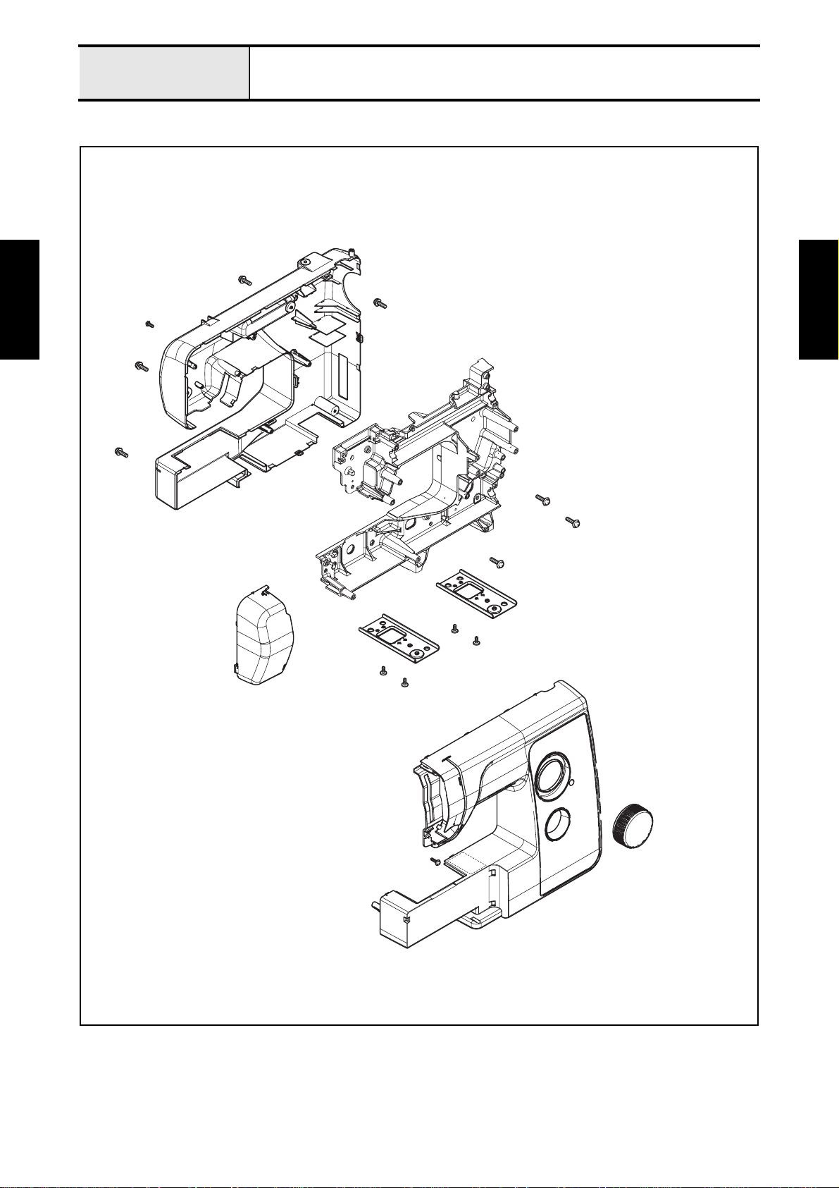
Main frame and Covers
Main frame and Covers location diagram
Basic of
Disassembly
Basic of
Disassembly
2 - 3
Page 16
Basic of Disassembly
Main frame and Covers
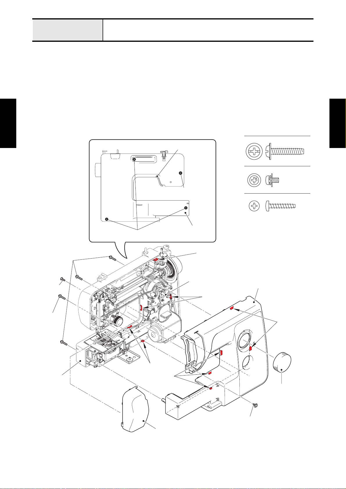
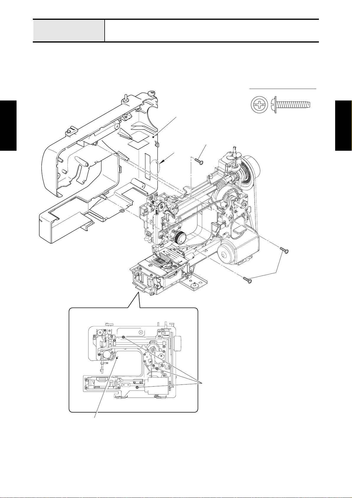
1 Removal of Face plate assy and Front cover assy
1. Remove the screw (taptite, cup P M4X20) from the rear cover side, and then open the bottom side of
face plate assy to remove the face plate assy from the rear cover assy.
→Refer to 3 - 3 Disassembly of Face plate assy.
2. Remove the pattern selecting dial from the shaft of pattern selecting unit assy.
3. Remove the screw (screw, pan (S/P washer) M3X6) from the front cover side. And remove the three
screws (taptite, cup P M4X20) and screw (taptite, bind P M3X16) from the rear cover side.
4. Release the five hooks of front cover assy from the five hook trays of rear cover assy, and then open
the bottom side of front cover assy to remove the front cover assy from the rear cover assy.
→Refer to 3 - 4 Disassembly of Rear cover assy.
Basic of
Disassembly
Taptite, cup P
M4X20
Taptite, bind P
M3X16
Taptite, cup P M4X20
Taptite, bind P M3X16
Taptite, cup P M4X20
(Face plate assy)
Rear cover assy
Hook tray
Shaft of pattern
selecting unit assy
Hook trays
Taptite, Cup P M4X20
Screw, Pan (S/P washer) M3X6
Taptite, Bind P M3X16
Front cover assy
Basic of
Disassembly
Taptite, cup P
M4X20
Rear cover
assy
Hooks
Hook trays
Hooks
Pattern
selecting dial
Screw, pan (S/P washer) M3X6
Face plate assy
2 - 4
Page 17
Basic of Disassembly
Main frame and Covers
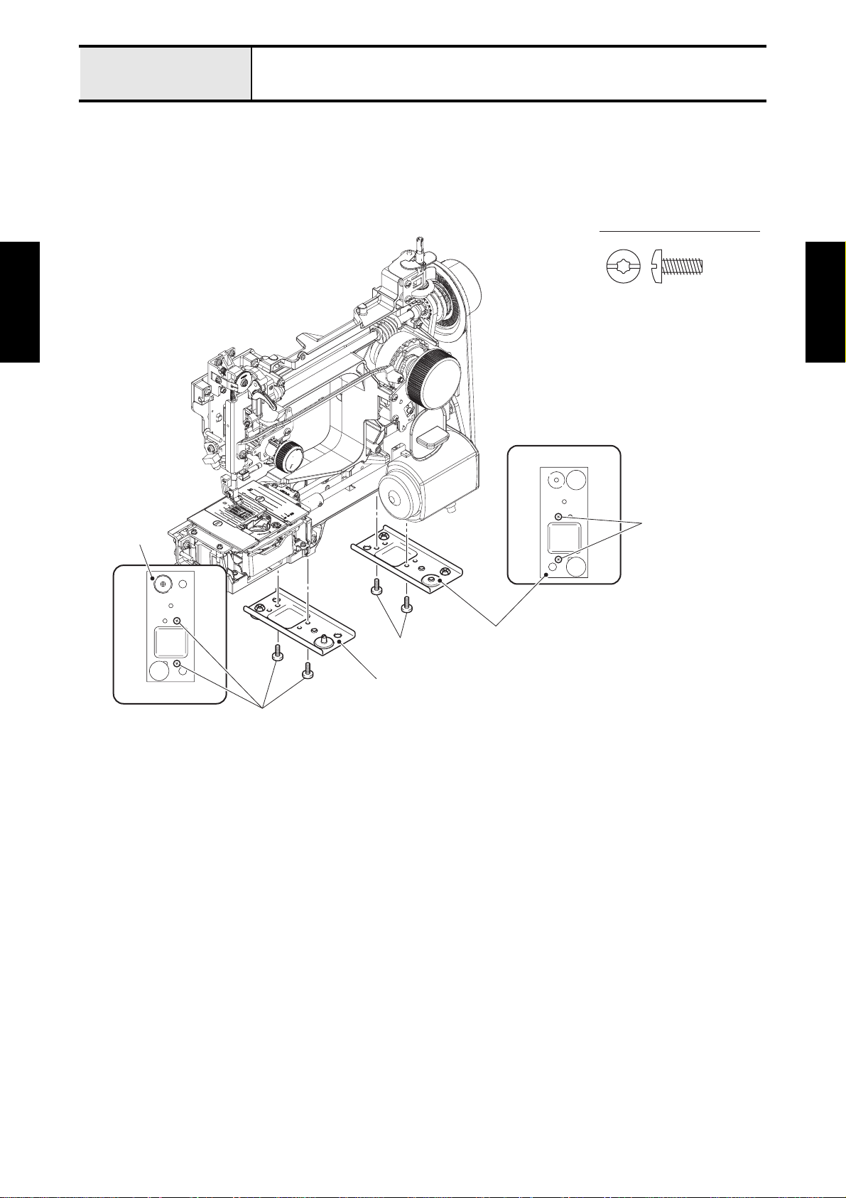
2 Removal of Rear cover assy and Base plate L/R
1. Pull down the presser foot lifter.
2. Remove the three screws (taptite, cup P M4X20), and then remove the rear cover assy fro m the arm
bed while the "A" of rear cover assy is bending.
Taptite, Cup P M4X20
Rear cover assy
Basic of
Disassembly
Taptite, cup P M4X20
"A"
Basic of
Disassembly
Taptite, cup P
M4X20
Presser foot lifter
Taptite, cup P M4X20
2 - 5
Page 18
Basic of Disassembly
3. Remove the two screws (taptite, bind S M4X10) to remove the base plate L from the bottom side of arm
bed.
4. Remove the two screws (taptite, bind S M4X10) to remove the base plate R from the bottom side of
arm bed.
Main frame and Covers
→Refer to 3 - 5 Disassembly of Base plate L/R.
Taptite, Bind S M4X10
Basic of
Disassembly
Base plate L
<bottom side>
Basic of
Disassembly
<bottom side>
Taptite, bind S M4X10
Base plate R
Taptite, bind S M4X10
Base plate L
Taptite, bind S M4X10
2 - 6
Page 19
Basic of Disassembly
Main motor unit
Main motor unit location diagram
Basic of
Disassembly
Basic of
Disassembly
2 - 7
Page 20
Basic of Disassembly
Main motor unit
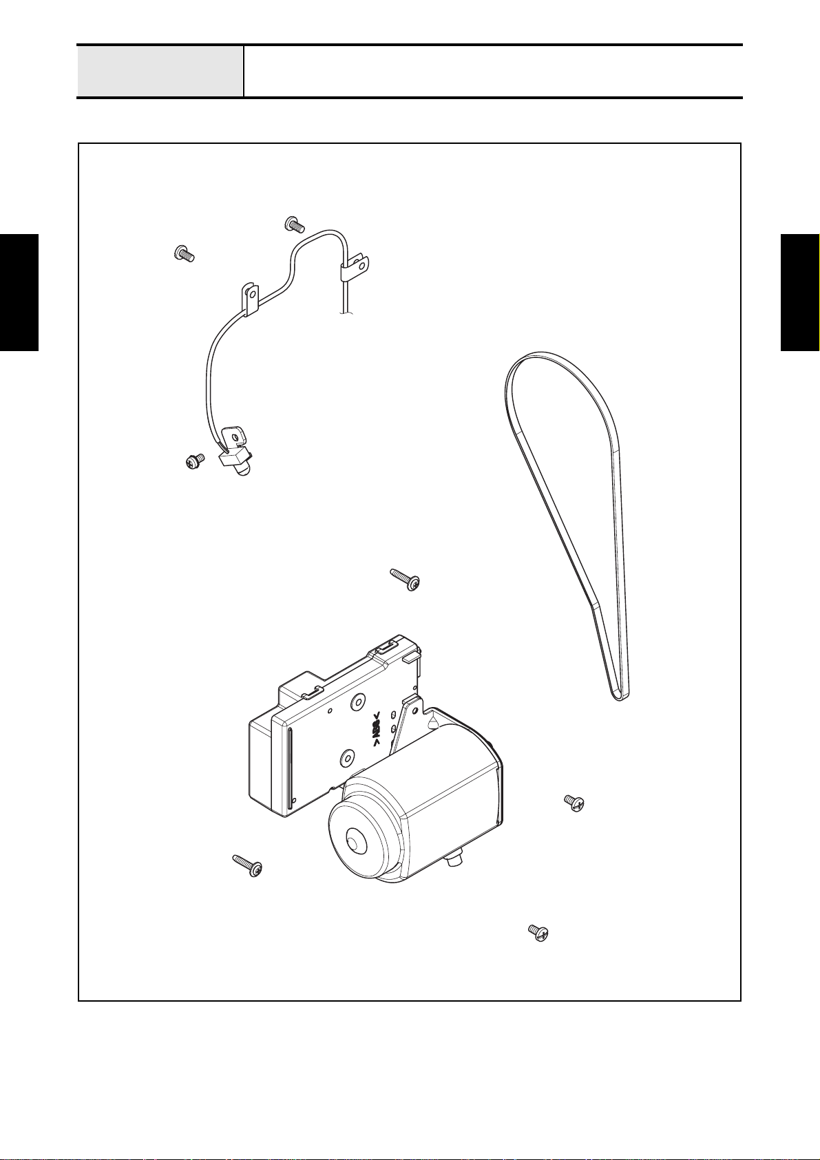
1 Removal of LED lamp assy
1. Remove the two screws (taptite, bind S M4X10) to remove the two cord clamps from the arm bed, and
then remove the two cord clamps from the lead wire of LED lamp assy.
2. Disconnect the connector of LED lamp assy from the PCB of motor 3P supply assy.
Taptite, Bind S M4X10
Taptite, bind S M4X10
Basic of
Disassembly
Lead wire of LED
lamp assy
PCB
Cord clamps
Motor 3P
supply assy
3. Remove the screw (screw, pan (S/P washer) M4X8) to remove the LED lamp assy from the b ase holder
assy.
Screw, Pan (S/P washer) M4X8
Connector of LED
lamp assy
Basic of
Disassembly
Screw, pan (S/P washer) M4X8
Base holder assy
LED lamp assy
2 - 8
Page 21
Basic of Disassembly
Main motor unit
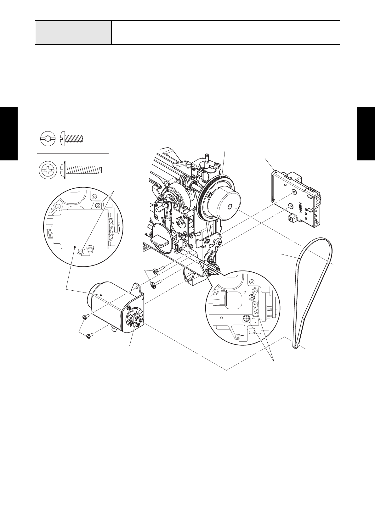
2 Removal of Motor 3P supply assy
1. Remove the timing belt from the T pulley and motor T-pulley.
2. Remove the two screws (taptite, bind S M4X10) to remove the motor assy of motor 3P supply assy
from the arm bed.
3. Remove the two screws (taptite, cup P M4X20) to remove the 3P socket unit of motor 3P supply assy
from the arm bed.
→Refer to 3 - 7 Disassembly of Motor 3P supply assy.
Taptite, Bind S M4X10
Basic of
Disassembly
Taptite, Cup P M4X20
Motor assy
Taptite, bind S
M4X10
Taptite, cup P
M4X20
T pulley
3P socket unit
Timing belt
Basic of
Disassembly
Taptite, bind S
M4X10
Motor T-pulley
Taptite, cup P M4X20
2 - 9
Page 22

Basic of Disassembly
Feed unit / Feed control
Feed unit / Feed control location diagram
Basic of
Disassembly
Basic of
Disassembly
2 - 10
Page 23
Basic of Disassembly
Feed unit / Feed control
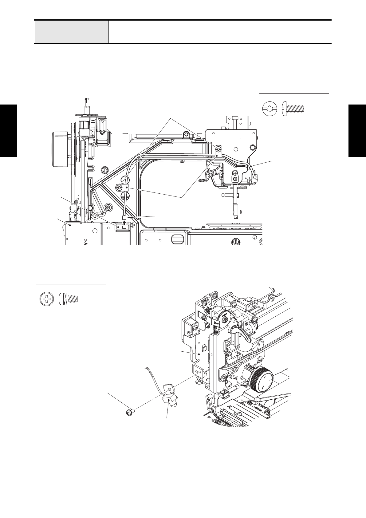
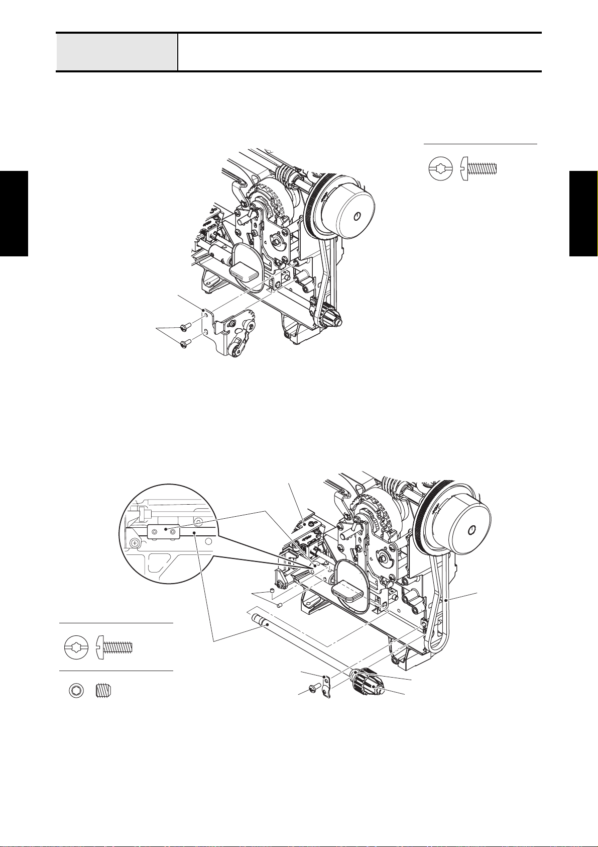
1 Removal of Tension pulley assy and Lower shaft B assy
1. Remove the two screws (taptite, bind S M4X10) to remove the tension pulley assy from th e arm bed.
→Refer to 3 - 9 Disassembly of Tension pulley assy.
Taptite, Bind S M4X10
Basic of
Disassembly
Basic of
Disassembly
Tension pulley assy
Taptite, bind S M4X10
2. Remove the timing belt from the timing pulley D of lower shaft B assy.
3. Remove the screw (taptite, bind S M4X10) to remove the bushing presser from the arm bed.
4. Remove the two screws (set screw, socket (CP) M5X5) from the fixed joint. And pull out the lower shaft
B assy from the fixed joint of feed module while lifting up the lower shaft bushing of lower shaft B assy.
→Refer to 3 - 10 Disassembly of Lower shaft B assy.
Feed module
Fixed joint
Taptite, Bind S M4X10
Set Screw, Socket (CP) M5X5
Hex wrench 2.5 mm
Set screw, socket
(CP) M5X5
Lower shaft B assy
Taptite, bind S M4X10
Timing belt
Bushing presser
Lower shaft bushing
Timing pulley D
2 - 11
Page 24
Basic of
Disassembly
Basic of Disassembly
Feed unit / Feed control
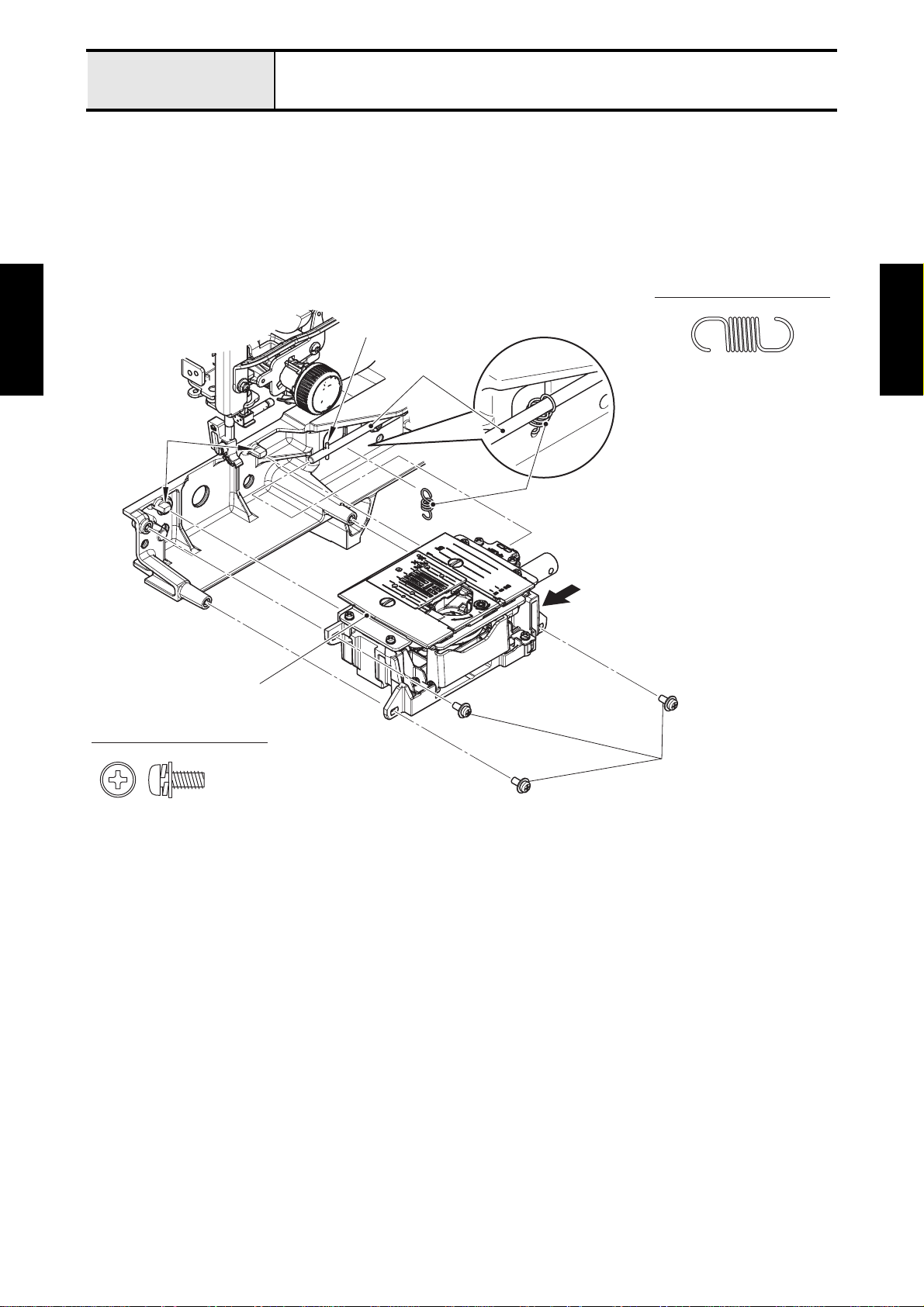
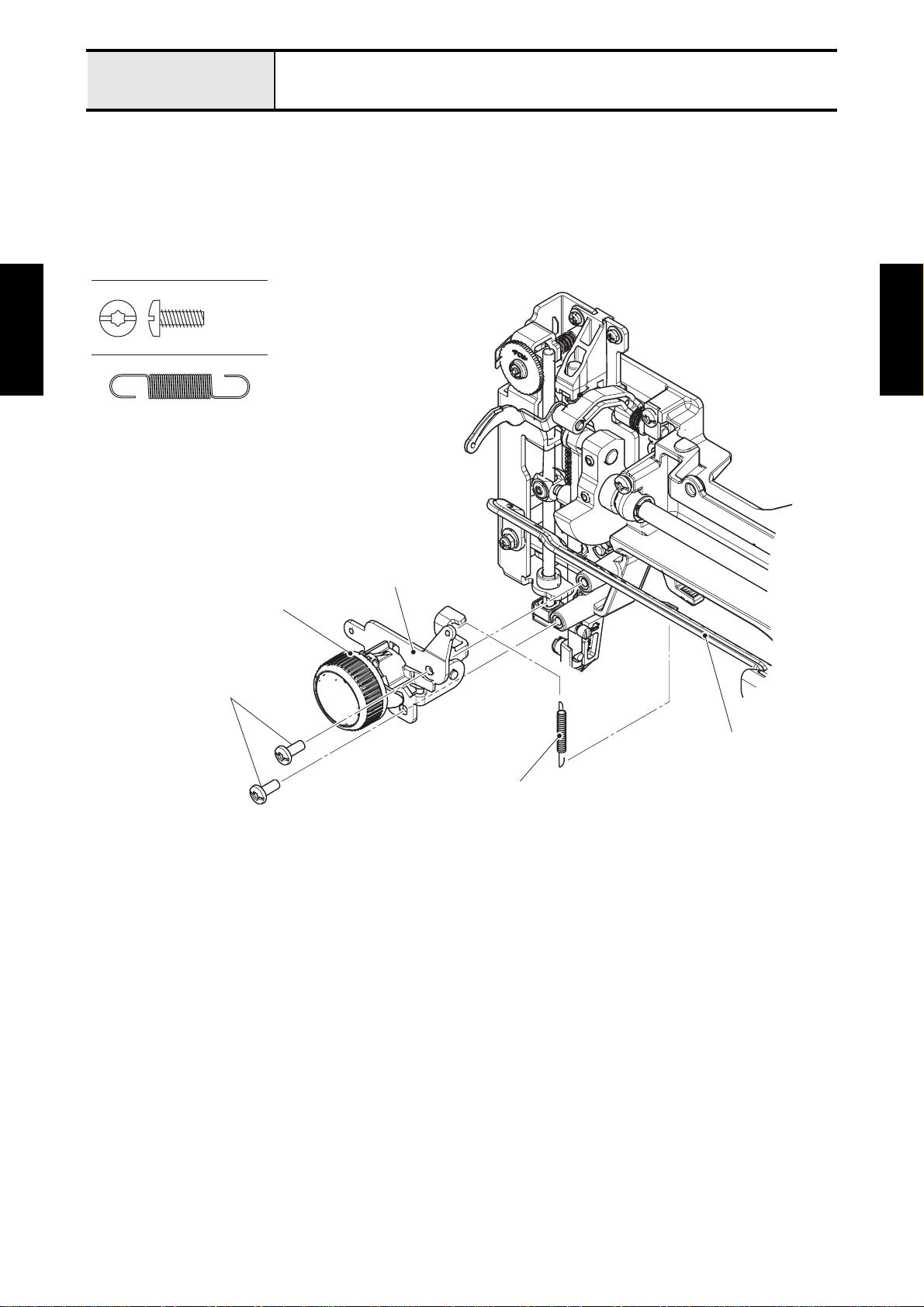
2 Removal of Feed module
1. Remove the spring (XF5134) from the feed adjusting shaft of feed connecting lever assy and the arm
bed.
2. Remove the three screws (screw, pan (S/P washer) M4X10) from the feed module. And lift up the feed
module to remove it from the two bosses on arm bed, and slide it in the direction of the arrow to remove
the feed adjuster of feed module from the feed adjusting shaft of feed connecting lever assy.
→Refer to 3 - 11 Disassembly of Feed module.
Spring (XF5134)
Pin
Feed adjusting
shaft
Bosses
Spring
(XF5134)
Basic of
Disassembly
Feed module
Screw, Pan (S/P washer) M4X10
Screw, pan
(S/P washer) M4X10
2 - 12
Page 25
Basic of Disassembly
Feed unit / Feed control
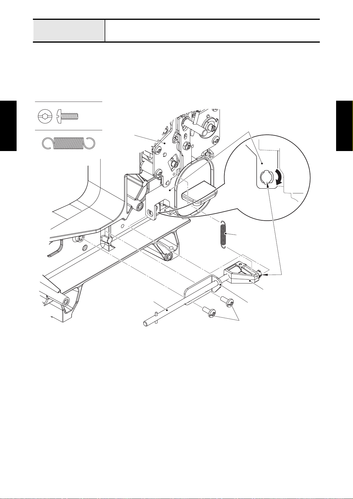
3 Removal of Feed connecting lever assy
1. Remove the spring extension C (XE9262) from the fee d connecting lever of feed connecting lever assy
and the pattern selecting unit assy.
2. Remove the two screws (taptite, bind S M4X10) to remove the feed adjusting shaft holder of feed
connecting lever assy from the arm bed. And turn the feed connecting lever of feed connecting lever
assy 90 degrees to remove it from the feed regulator plate B of pattern selecting unit assy.
Taptite, Bind S M4X10
Basic of
Disassembly
Spring extension C (XE9262)
Pattern selecting
unit assy
Feed connecting lever assy
Feed regulator plate B
Basic of
Disassembly
90°
Spring
extension C
(XE9262)
Boss
Feed connecting lever
Feed adjusting shaft holder
2 - 13
Taptite, bind S M4X10
Page 26

Basic of Disassembly
Needle threading mechanism
Needle threading mechanism location diagram
Basic of
Disassembly
Basic of
Disassembly
2 - 14
Page 27
Basic of Disassembly
Needle threading mechanism
1 Removal of Thread tension dial assembly
1. Remove the spring (XF3522) from the tension control holder assy of thread ten sion dial assem bly and
the zigzag connecting rod.
2. Remove the two screws (taptite, bind S M4X10) to remove the thread tension dial assembly from the
arm bed.
→Refer to 3 - 20 Disassembly of Thread tension dial assembly.
Taptite, Bind S M4X10
Basic of
Disassembly
Spring (XF3522)
Thread tension dial assembly
Taptite, bind S M4X10
Basic of
Disassembly
Tension control holder assy
Zigzag connecting rod
Spring (XF3522)
2 - 15
Page 28
Basic of Disassembly
Pattern selecting mechanism
Pattern selecting mechanism location diagram
Basic of
Disassembly
Basic of
Disassembly
2 - 16
Page 29
Basic of Disassembly
Pattern selecting mechanism
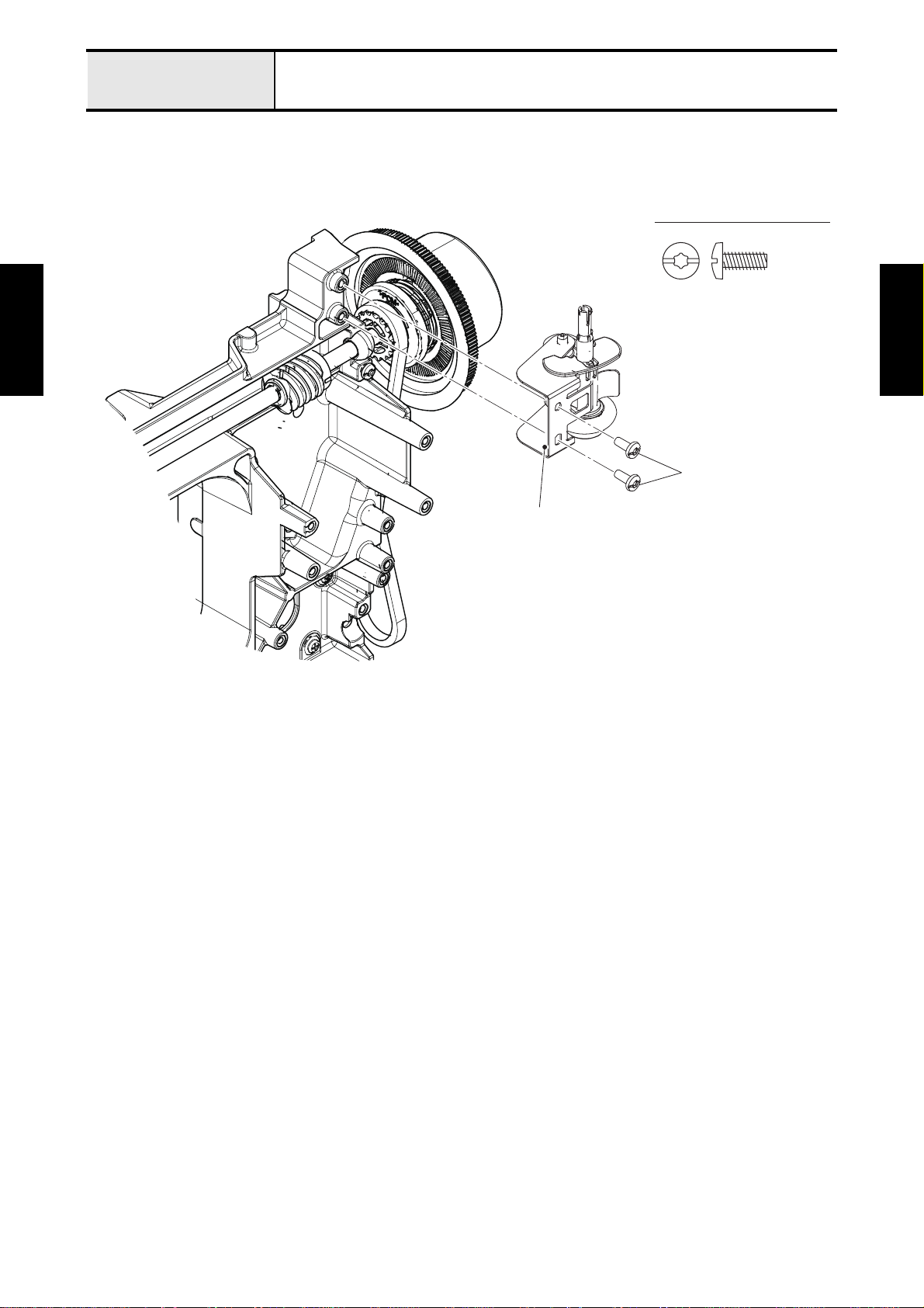
1 Removal of Pattern selecting unit assy
1. Remove the screw (screw, pan M3X10) to remove the zigzag adjusting nut from the base holder assy
of needle unit supply assy. And remove the retaining ring E4 to remove the zigzag connecting rod from
the shaft of pattern selecting unit assy.
Screw, Pan M3X10
Needle unit supply assy
Basic of
Disassembly
Shaft
Pattern selecting
unit assy
Retaining ring E4
Zigzag connecting rod
Zigzag adjusting nut
Screw, pan M3X10
2. Remove the four screws (taptite, bind S M4X10) to remove the pattern selecting unit assy from the arm
bed.
→Refer to 3 - 22 Disassembly of Pattern selecting unit assy.
Taptite, Bind S M4X10
Basic of
Disassembly
Pattern selecting unit assy
2 - 17
Taptite, bind S M4X10
Page 30
Basic of Disassembly
Bobbin winder, Upper shaft, Needle-presser module
Bobbin winder, Upper shaft, Needle-presser module location diagram
Basic of
Disassembly
Basic of
Disassembly
2 - 18
Page 31
Basic of Disassembly
Bobbin winder, Upper shaft, Needle-presser module
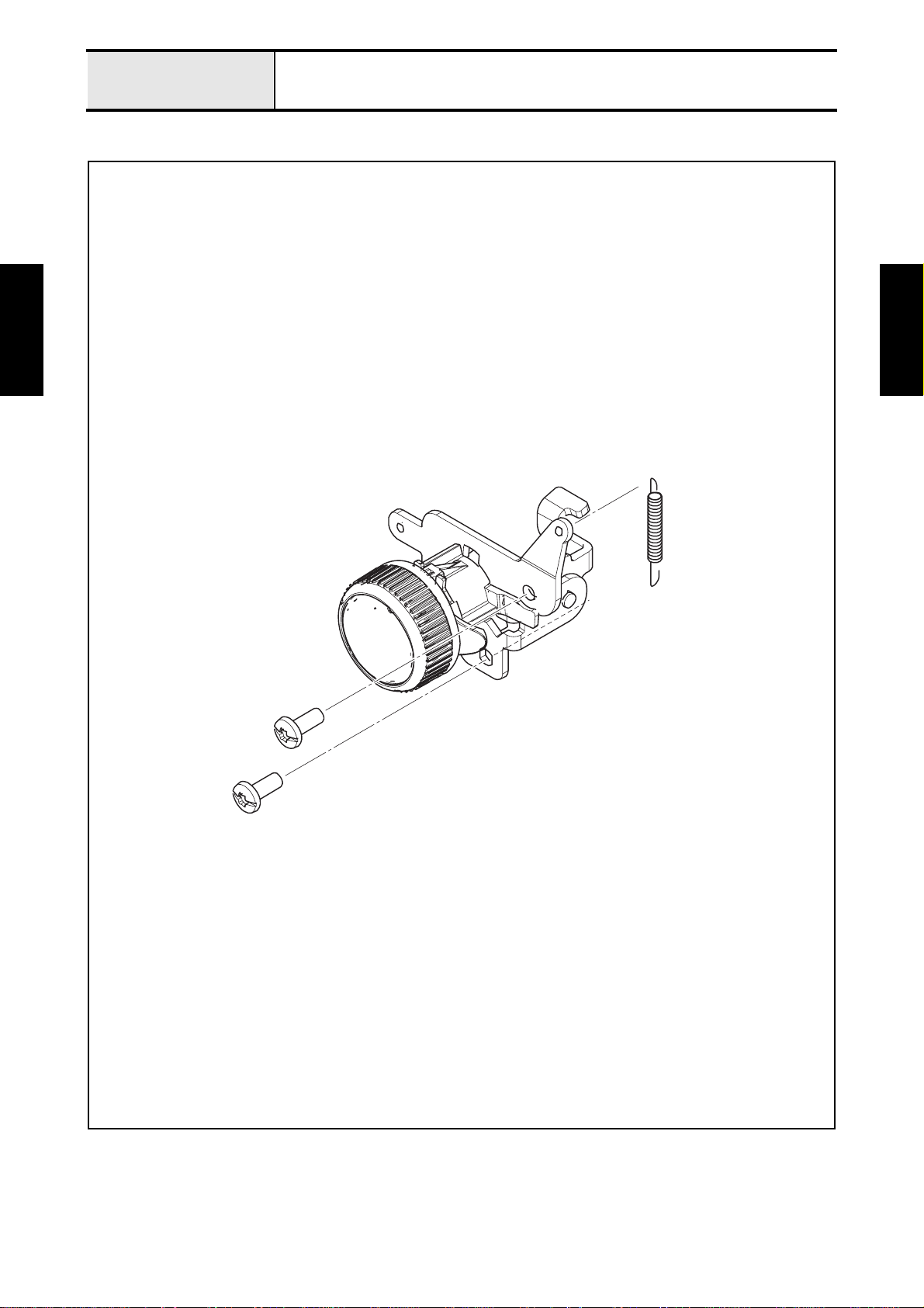
1 Removal of Bobbin winder assy
1. Remove the two screws (taptite, bind S M4X10) to remove the bobbin winder assy from the arm bed.
→Refer to 3 - 24 Disassembly of Bobbin winder assy.
Taptite, Bind S M4X10
Basic of
Disassembly
Basic of
Disassembly
Taptite, bind S M4X10
Bobbin winder assy
2 - 19
Page 32

Basic of Disassembly
Bobbin winder, Upper shaft, Needle-presser module
2 Removal of Upper shaft assy
1. Remove the timing belt from the upper shaft assy.
2. Remove the screw (set screw, socket (FT) M5X5) from the thread take- up counter weight of upp er shaft
assy.
3. Remove the two screws (taptite, bind S M4X10) to remove the two bushing pressers from the arm bed.
And remove the two lower shaft bushings of upper shaft assy from the arm bed, and then slide the
upper shaft assy in the direction of the arrow to remove the thread take-up counter weight of upper
shaft assy from the shaft of thread take-up lever.
→Refer to 3 - 25 Disassembly of Upper shaft assy.
Basic of
Disassembly
Mounting positions
Shaft of thread take-up lever
Thread take-up
counter weight
Upper shaft assy
Lower shaft bushing
Bushing pressers
Taptite, bind S M4X10
Lower shaft bushing
Set screw, socket (FT) M5X5
Timing belt
Set Screw, Socket (FT) M5X5
Hex wrench 2.5 mm
Taptite, Bind S M4X10
Basic of
Disassembly
2 - 20
Page 33

Basic of Disassembly
Bobbin winder, Upper shaft, Needle-presser module
3 Removal of Needle-presser module
1. Remove the screw (screw, bind M4X8) to remove the stopper plate from the back side of arm bed.
2. Remove the screw (cup screw M3X20) from the back side of arm bed.
Screw, Bind M4X8
Cup screw M3X20
Basic of
Disassembly
Basic of
Disassembly
Stopper plate
Screw, bind M4X8
Cup screw M3X20
2 - 21
Page 34

Basic of Disassembly
3. Remove the two screws (screw, bind M4X10) to remove the two presser plates from the arm bed. And
remove the needle-presser module from the arm bed.
→Refer to 3 - 26 Disassembly of Needle-presser module.
Bobbin winder, Upper shaft, Needle-presser module
Screw, Bind M4X10
Basic of
Disassembly
Basic of
Disassembly
Presser plates
Needle-presser module
Screw, bind M4X10
2 - 22
Page 35

Basic of Assembly
Bobbin winder, Upper shaft, Needle-presser module
Bobbin winder, Upper shaft, Needle-presser module location diagram
Basic of
Assembly
Basic of
Assembly
2 - 23
Page 36

Basic of Assembly
Bobbin winder, Upper shaft, Needle-presser module
1 Attachment of Needle-presser module
1. Set the shaft of needle-presser module to the two mounting positions on arm bed, and insert the tab of
arm bed into the positioning hole of needle-presser module.
2. Attach the presser plate to the arm bed with th e scr ew (screw, bind M4X10). (2 locations)
Screw, Bind M4X10
Mounting positions
Basic of
Assembly
Tab
Shaft
Positioning hole
Needle-presser module
Presser plates
Screw, bind M4X10
Basic of
Assembly
2 - 24
Page 37

Basic of Assembly
3. Tighten the screw (cup screw M3X20) temporarily to the back side of arm bed.
4. Attach the stopper plate to the back side of arm bed with the screw (screw, bind M4X8).
Bobbin winder, Upper shaft, Needle-presser module
→Refer to 3 - 32 Assembly of Needle-presser module.
Cup screw M3X20
Screw, Bind M4X8
Basic of
Assembly
Stopper plate
Screw, bind M4X8
Cup screw M3X20
Basic of
Assembly
2 - 25
Page 38

Basic of Assembly
Bobbin winder, Upper shaft, Needle-presser module
2 Attachment of Upper shaft assy
1. Insert the thread take-up counter weight of the upper shaft assy into the shaft of needle bar crank rod
assy, and set the two lower shaft bush ings of upper shaft assy to the two moun ting positions on arm
bed. And attach the two bushing pressers to the arm bed with the two screws (taptite, bind S M4X10).
2. Align the D cut surface of needle bar crank rod assy with the screw hole on thread take-up counter
weight, and secure it with the screw (set screw, socket (FT) M5X5).
3. Pass the timing belt to the upper shaft assy.
→Refer to 3 - 36 Assembly of Upper shaft assy.
Basic of
Assembly
Shaft of thread take-up lever
Needle bar
crank rod assy
Mounting positions
D cut surface
Thread take-up
counter weight
Thread take-up counter weight
Screw hole
Upper shaft assy
Upper shaft assy
Lower shaft bushing
Bushing pressers
Lower shaft bushing
Set screw, socket (FT) M5X5
Timing belt
Taptite, bind S M4X10
Taptite, Bind S M4X10
Set Screw, Socket (FT) M5X5
Hex wrench 2.5 mm
Basic of
Assembly
2 - 26
Page 39

Basic of Assembly
Bobbin winder, Upper shaft, Needle-presser module
3 Attachment of Bobbin winder assy
1. Attach the bobbin winder assy to the arm bed with the two screws (taptite, bind S M4X10).
→Refer to 3 - 37 Assembly of Bobbin winder assy.
Taptite, Bind S M4X10
Basic of
Assembly
Bobbin winder assy
Taptite, bind S M4X10
Basic of
Assembly
2 - 27
Page 40

Basic of Assembly
Pattern selecting mechanism
Pattern selecting mechanism location diagram
Basic of
Assembly
Basic of
Assembly
2 - 28
Page 41

Basic of Assembly
Pattern selecting mechanism
1 Lubrication
Lubrication point Lubricating oil type Quantity of lubrication
1 Z finger frame assy 1 place EPNOC AP (N) 0 Rice-grain size
2 Zigzag adjusting nut 1 place EPNOC AP (N) 0 Rice-grain size
Basic of
Assembly
Z finger frame assy
Basic of
Assembly
1
2
Zigzag adjusting nut
2 - 29
Page 42

Basic of Assembly
Pattern selecting mechanism
2 Attachment of Pattern selecting unit assy
1. Match the mark on worm gear of upper shaft assy with the mark on gear of pattern selecting unit assy,
and attach the pattern selecting unit assy to the arm bed with the four screws (taptite, bind S M4X10).
Basic of
Assembly
Upper shaft assy
Worm gear
Pattern selecting
unit assy
Marks
Gear
Taptite, Bind S M4X10
Taptite, bind S M4X10
Basic of
Assembly
2 - 30
Page 43

Basic of Assembly
Pattern selecting mechanism
2. Set the zigzag connecting rod to the shaft of pattern selecting un it assy, and secure it with the retaining
ring E4. And set the zigzag adjusting nut to the zigzag connecting rod, and set them to the base holder
assy of needle unit supply assy, and tighten the screw (screw, pan M3X10) temporarily.
*Key point
• Confirm that place the zigzag adjusting nut with the larger en d facing the top side.
• Fully tighten the screw after performing “4 - 10 Three point needle drop”.
→Refer to 3 - 40 Assembly of Pattern selecting unit assy.
Screw, Pan M3X10
Basic of
Assembly
Zigzag adjusting nut
Screw, pan M3X10
Base holder assy
Needle unit supply assy
Zigzag connecting rod
Zigzag adjusting nut
Screw, pan M3X10
Shaft
Pattern selecting
unit assy
Retaining ring E4
Basic of
Assembly
2 - 31
Page 44
Basic of Assembly
Needle threading mechanism
Needle threading mechanism location diagram
Basic of
Assembly
Basic of
Assembly
2 - 32
Page 45

Basic of Assembly
Needle threading mechanism
1 Attachment of Thread tension dial assembly
1. Attach the thread tension dial assembly to the arm bed with the two screws (taptite, bind S M4X10).
*Key point
• Confirm that there is "A" of upper tension control releaser on the upper side of presser foot lifter as shown in
the illustration below.
2. Hang the spring (XF3522) to the tension control holder assy and the zigzag connecting rod.
→Refer to 3 - 42 Assembly of Thread tension dial assembly.
Taptite, Bind S M4X10
Basic of
Assembly
Spring (XF3522)
Presser foot lifter
Thread tension dial assembly
Taptite, bind S M4X10
"A"
Upper tension control releaser
Tension control holder assy
Zigzag connecting rod
Basic of
Assembly
Spring (XF3522)
2 - 33
Page 46

Basic of Assembly
Feed unit / Feed control
Feed unit / Feed control location diagram
Basic of
Assembly
Basic of
Assembly
2 - 34
Page 47

Basic of Assembly
Feed unit / Feed control
1 Lubrication
Lubrication point Lubricating oil type Quantity of lubrication
1 Feed adjusting shaft holder 1 place EPNOC AP (N) 0 Rice-grain size
2 Feed connecting lever 1 place EPNOC AP (N) 0 Rice-grain size
Basic of
Assembly
Feed adjusting shaft holder
Basic of
Assembly
Feed connecting lever
1
2
2 - 35
Page 48

Basic of Assembly
Feed unit / Feed control
2 Attachment of Feed connecting lever assy
1. Insert the boss of feed connecting lever into the positioning hole of feed regu lator plate B, and turn it 90
degrees. And attach the feed adjusting shaft holder of feed connecting lever assy to the arm bed with
the two screws (taptite, bind S M4X10).
2. Attach the spring extension C (XE9262) to the feed connecting lever and the pattern selecting unit
assy.
Taptite, Bind S M4X10
Basic of
Assembly
Spring extension C (XE9262)
Pattern selecting unit assy
Feed connecting lever assy
Feed regulator plate B
Spring
extension C
(XE9262)
Feed adjusting shaft holder
Positioning hole
Boss
Feed connecting lever
Basic of
Assembly
2 - 36
Taptite, bind S M4X10
Page 49

Basic of
Assembly
Basic of Assembly
Feed unit / Feed control
3 Attachment of Feed module
1. Insert the feed adjuster into the feed adjusting shaft of feed connecting lever assy, a nd set the pin of the
feed adjusting shaft to the two slits of feed adjuster. And insert th e two positioning holes of back side of
feed module into the two tabs of arm bed, and set the feed module to the arm bed, and secure it with
the three screws (screw, pan (S/P washer) M4X10).
2. Attach the spring (XF5134) to the feed adjusting shaft of feed connecting lever assy and the arm bed as
shown in the illustration below.
→Refer to 3 - 45 Assembly of Feed module.
Spring (XF5134)
Pin
Feed adjusting
shaft
Tabs
Pin
Spring
(XF5134)
Feed adjusting
shaft
Basic of
Assembly
Feed module
Screw, Pan (S/P washer) M4X10
Feed adjuster
Screw, pan
(S/P washer) M4X10
2 - 37
Page 50

Basic of
Assembly
Basic of Assembly
Feed unit / Feed control
4 Attachment of Lower shaft B assy and Tension pulley assy
1. Insert the lower shaft B assy into the fixed joint, and set the lower shaft bushing of the lower shaft B
assy to the mounting position of arm bed. And attach the bushing presser to the arm bed with the screw
(taptite, bind S M4X10). And tighten the two screws (set screw, socket (CP) M5X5) temporarily to the
fixed joint.
*Key point
• Fully tighten the two screws after performing “4 - 12 Needle bar rising”.
2. Hang the timing belt to the timing pulley D of lower shaft B assy.
→Refer to 3 - 53 Assembly of Lower shaft B assy.
Feed module
Fixed joint
Set screw,
socket (CP)
M5X5
Timing belt
Basic of
Assembly
Taptite, Bind S M4X10
Lower shaft B assy
Set Screw, Socket (CP) M5X5
Hex wrench 2.5 mm
Bushing presser
Taptite, bind S M4X10
Lower shaft bushing
Timing pulley D
3. Attach the tension pulley assy to the arm bed with the two screws (taptite, bind S M4X10).
→Refer to 3 - 54 Assembly of Tension pulley assy.
Taptite, Bind S M4X10
Tension pulley assy
Mounting position
Taptite, bind S M4X10
2 - 38
Page 51

Basic of Assembly
Feed unit / Feed control
5 Phase matching of Upper shaft and Lower shaft
1. When set the groove of upper shaft pulley frontward by rotating the pulley of upper shaft, and set the
mark of outer rotary hook assy frontward by rotating the lower shaft A assy, and set the feed cam with
larger end facing backward, and tighten the two screws (set screw, socket (CP) M5X5) of fixed joint.
Set Screw, Socket (CP) M5X5
Basic of
Assembly
Hex wrench 2.5 mm
Feed cam
Outer rotary
hook assy
Upper shaft pulley
Groove
Lower shaft A assy
Basic of
Assembly
Mark
Fixed joint
Set screw, socket (CP) M5X5
2 - 39
Page 52

Basic of Assembly
Main motor unit
Main motor unit location diagram
Basic of
Assembly
Basic of
Assembly
2 - 40
Page 53

Basic of Assembly
Main motor unit
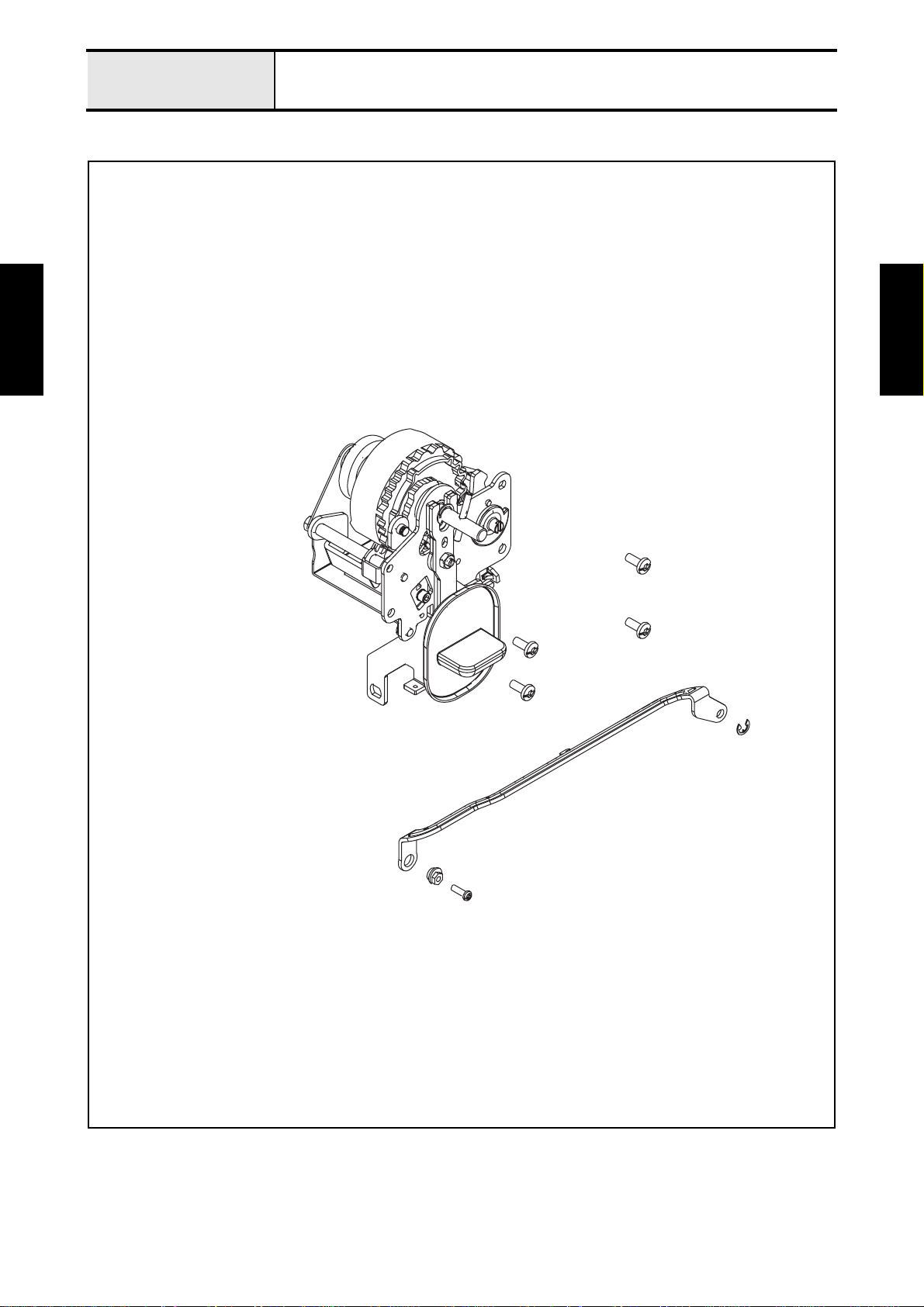
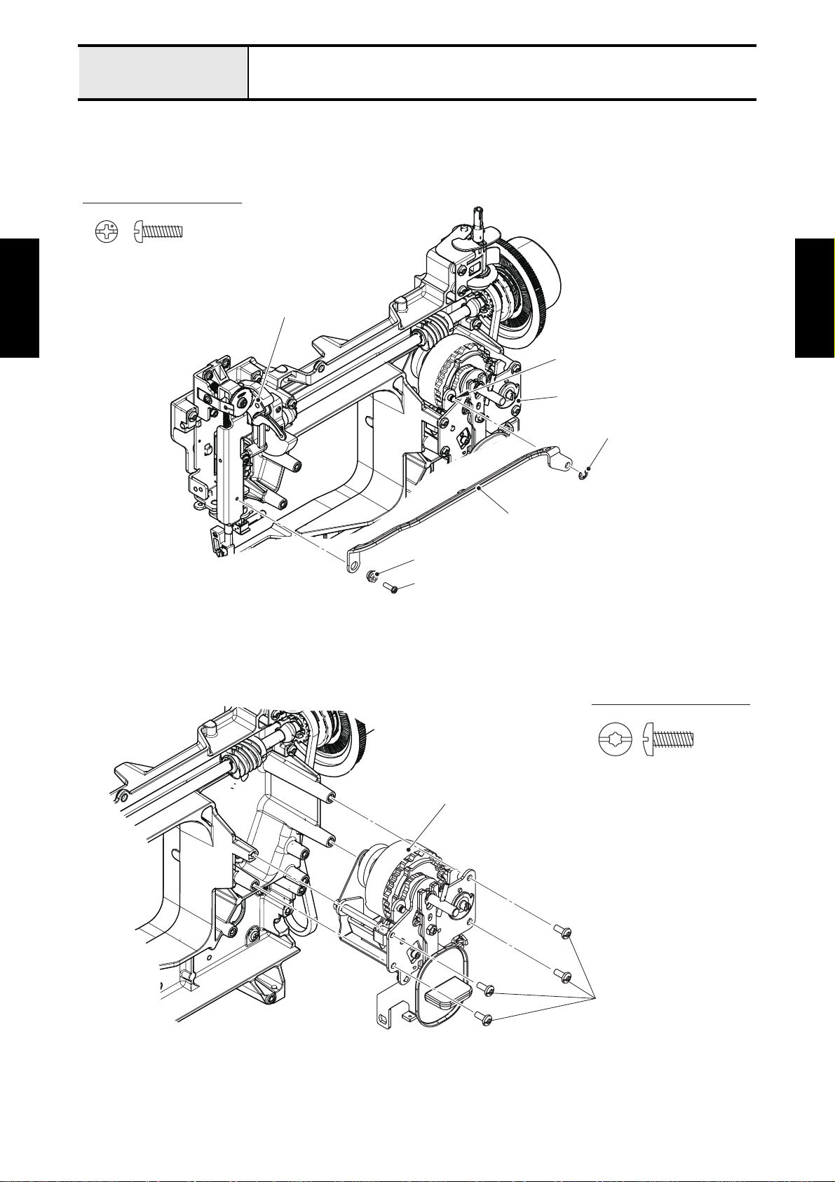
1 Attachment of Motor 3P supply assy
1. Insert the two pins of 3P sock et un it of motor 3 P su pply assy int o the tw o positio ni ng hole s of ar m be d,
and secure it to the arm bed with the two screws (taptite, cup P M4X20).
2. Attach the motor assy of motor 3P supply assy to the arm bed with the two screws (taptite, bind S
M4X10).
3. Hang the timing belt on the T pulley and the motor T-pulley. And set the motor tension pulley on the
timing belt so that pushing it.
→Refer to 3 - 56 Assembly of Motor 3P supply assy.
Taptite, Cup P M4X20
Basic of
Assembly
Taptite, Bind S M4X10
Motor assy
Taptite, bind S
M4X10
Taptite, cup P
M4X20
Positioning holes
T pulley
Motor tension pulley
3P socket unit
Pins
Timing belt
Pin
Basic of
Assembly
Taptite, bind S
M4X10
Motor T-pulley
Pin
Taptite, cup P M4X20
2 - 41
Page 54

Basic of Assembly
Main motor unit
2 Attachment of LED lamp assy
1. Align the boss of LED lamp assy with the positioning hole of base holder assy, and attach it with the
screw (screw, pan (S/P washer) M4X8).
Screw, Pan (S/P washer) M4X8
Base holder assy
Basic of
Assembly
Positioning hole
Boss
Screw, pan (S/P washer) M4X8
LED lamp assy
2. Connect the connector of LED lamp assy to the PCB of motor 3P supply assy.
3. Set the cord clamp to the lead wire of LED lamp assy, and attach it to the arm bed with the screw
(taptite, bind S M4X10). (2 locations)
Taptite, Bind S M4X10
Taptite, bind S M4X10
Basic of
Assembly
PCB
Motor 3P supply assy
Lead wire of LED
lamp assy
Cord clamps
Connector of LED
lamp assy
2 - 42
Page 55

Basic of Assembly
Main frame and Covers
Main frame and Covers location diagram
Basic of
Assembly
Basic of
Assembly
2 - 43
Page 56

Basic of Assembly
Main frame and Covers
1 Attachment of Rear cover assy and Base plate L/R
1. Attach the base plate R to the bottom side of arm bed with the two screws (taptite, bind S M4X10).
2. Attach the base plate L to the bottom side of arm bed with the two screws (taptite, bind S M4X10).
→Refer to 3 - 58 Assembly of Base plate L/R.
Taptite, Bind S M4X10
Basic of
Assembly
Base plate L
<bottom side>
Taptite, bind S M4X10
Taptite, bind S M4X10
Base plate L
Base plate R
<bottom side>
Taptite, bind S M4X10
Basic of
Assembly
2 - 44
Page 57

Basic of
Assembly
Basic of Assembly
3. Pull down the presser foot lifter.
4. Set the rear cover assy to the arm bed, and secure it with the three screws (taptite, cup P M4X20).
Main frame and Covers
→Refer to 3 - 59 Assembly of Rear cover assy.
Taptite, Cup P M4X20
Rear cover assy
Taptite, cup P M4X20
Basic of
Assembly
Presser foot lifter
Taptite, cup P
M4X20
Taptite, cup P M4X20
2 - 45
Page 58

Basic of Assembly
Main frame and Covers
2 Attachment of Face plate assy and Front cover assy
1. Set the front cover assy to the rear cover assy, and hang the five hooks of front cover assy on the five
hook trays of rear cover assy.
2. Secure the front cover assy to the arm bed with the three screws (taptite, cup P M4X20) and the screw
(taptite, bind P M3X16) from the rear cover side. And tighten the screw (screw, pan (S/P washer)
M3X6) to the front cover side.
3. Attach the pattern selecting dial to the shaft of pattern selecting unit assy.
4. Insert the pin of face plate assy into the positioning hole of front cover assy, and set the face plate assy
to the rear cover assy, and secure it with the screw (taptite, cup P M4X20) from the rear cover side.
→Refer to 3 - 60 Assembly of Face plate assy.
Basic of
Assembly
Taptite, cup P M4X20
Taptite, bind P
M3X16
Taptite, cup P M4X20
Taptite, bind P M3X16
Taptite, cup P M4X20
(Face plate assy)
Hook tray
Shaft of pattern
selecting unit assy
Hook trays
Taptite, Cup P M4X20
Screw, Pan (S/P washer) M3X6
Taptite, Bind P M3X16
Front cover assy
Basic of
Assembly
Taptite, cup P
M4X20
Rear cover assy
Face plate assy
Hook trays
Hooks
Pin
2 - 46
Hooks
Pattern
selecting dial
Screw, pan (S/P washer) M3X6
Positioning hole
Page 59

Application of
3
Disassembly/Assembly
In this chapter, explains the disassembly and assembly of
the each module. When fix and replace the each module,
use this chapter.
Disassembly Main frame and Covers................... 3 - 2
Main motor unit................................ 3 - 6
Feed unit.......................................... 3 - 8
Needle threading mechanism........ 3 - 19
Pattern selecting mechanism ........ 3 - 21
Bobbin winder, Upper shaft,
Needle-Presser module................. 3 - 23
Assembly Bobbin winder, Upper shaft,
Needle-Presser module................. 3 - 30
Pattern selecting mechanism ........ 3 - 38
Needle threading mechanism........ 3 - 41
Feed unit........................................ 3 - 43
Main motor unit.............................. 3 - 55
Main frame and Covers................. 3 - 57
3 - 1
Page 60

Application of
f
Main frame and Covers
Disassembly
Main frame and Covers location diagram
Disassembly
Application o
Disassembly
Application of
3 - 2
Page 61

Application of
f
Main frame and Covers
Disassembly
1 Disassembly of Face plate assy
1. Remove the screw (taptite, bind B M3X1 0) to remove the face plate cutter holder and the NT lower
thread cutter from the face plate assy.
Taptite, Bind B M3X10
Face plate assy
NT lower thread cutter
Face plate cutter holder
Disassembly
Application o
Taptite, bind B M3X10
Disassembly
Application of
3 - 3
Page 62

Application of
f
Main frame and Covers
Disassembly
2 Disassembly of Rear cover assy
1. Remove the spool pin from the rear cover while pulling the spool pin spring.
2. Remove the spool pin spring from the rear cover.
3. Remove the spool pin stand from the rear cover.
4. Remove the screw (taptite, pan P (S/P W) 3X12) to remove the bobbin presser from the rear cover.
5. Remove the screw (taptite, cup P M4X20) to re mo ve the threa d gu id e ass y fro m th e re ar cover.
Spool pin
Taptite, pan P (S/P W) 3X12
Disassembly
Application o
Spool pin spring
Spool pin stand
Rear cover
Bobbin presser
Positioning groove
Spool pin spring
Thread guide assy
Taptite, cup P M4X20
Disassembly
Application of
Taptite, Pan P (S/P W) 3X12
Taptite, Cup P M4X20
3 - 4
Page 63

Application of
f
Main frame and Covers
Disassembly
3 Disassembly of Base plate L/R
1. Remove the base rubber A from the base plate L.
2. Remove the adjusting screw assy from the base plate L.
3. Remove the two base rubbers A from the base plate R.
Base plate R
Base plate L
Disassembly
Application o
Base rubber A
Base rubbers A
Adjusting screw assy
Disassembly
Application of
3 - 5
Page 64

Application of
f
Main motor unit
Disassembly
Main motor unit location diagram
Disassembly
Application o
Disassembly
Application of
3 - 6
Page 65

Application of
f
Main motor unit
Disassembly
1 Disassembly of Motor 3P supply assy
1. Remove the retaining ring E3 to remove the frange and motor T-pulley from the shaft of motor 3P
supply assy.
Disassembly
Application o
Motor 3P supply assy
Shaft
Motor T-pulley
Frange
Retaining ring E3
Disassembly
Application of
3 - 7
Page 66

Application of
f
Feed unit
Disassembly
Feed unit location diagram
Disassembly
Application o
Disassembly
Application of
3 - 8
Page 67

Application of
f
Feed unit
Disassembly
1 Disassembly of Tension pulley assy
1. Remove the retaining ring E3 to remove the motor tension pulley assy and the spring (XF3404) from
the shaft of tension pulley holder B assy.
2. Remove the screw (screw, pan (S/P washer) M4X8) to remove the M tension pulley stopper from the
tension pulley holder B assy.
3. Remove the screw (screw, pan (S/P washer) M4X8) to remove the tension pulley sub assy from the
tension pulley holder B assy.
Spring (XF3404)
Tension pulley sub assy
Shaft
Disassembly
Application o
Tension pulley holder B assy
Screw, Pan (S/P washer) M4X8
M tension pulley stopper
Screw, pan (S/P washer) M4X8
Spring (XF3404)
Motor tension pulley assy
Boss
Retaining ring E3
Disassembly
Application of
3 - 9
Page 68

Application of
f
Feed unit
Disassembly
2 Disassembly of Lower shaft B assy
1. Remove the lower shaft bushing from the lower shaft B sub assy.
2. Remove the retaining ring E6 to remove the timing pulley D from the lower shaft B sub assy.
Retaining ring E6
Disassembly
Application o
Lower shaft bushing
Lower shaft B sub assy
Timing pulley D
Disassembly
Application of
3 - 10
Page 69

Application of
f
Feed unit
Disassembly
3 Disassembly of Feed module
1. Remove the two screws (screw needle plate) to remove the needle plate B from the need le plate holder
assy.
2. Remove the two screws (screw, pan (P washer) M2.6X6) to remove the needle p late A fro m the nee dle
plate B.
3. Remove the four screws (taptite, pan P (S/P W) 3X12) to remove the needle plate holder assy from the
feed holder.
4. Remove the screw (screw, bind M3X3), and remove the spring plate and the spring assist plate from
the needle plate holder.
5. Remove the inner rotary hook assy from the outer rotary hook assy.
6. Remove the sheet from the feed adjuster holder.
Disassembly
Application o
Screw needle plate
Needle plate A
Screw, pan
(P washer)
M2.6X6
Taptite, pan P (S/P W) 3X12
Screw needle plate
Needle plate B
Spring plate
Needle plate holder
Spring assist plate
Inner rotary hook assy
Screw, bind
M3X3
Sheet
Feed
adjuster
holder
Disassembly
Application of
Screw, Pan (P washer) M2.6X6
Taptite, Pan P (S/P W) 3X12
Screw, Bind M3X3
Feed holder
Pins
Outer rotary hook assy
3 - 11
Page 70

Application of
f
Feed unit
Disassembly
7. Remove the two screws (bolt, socket M3X5) to remove the feed dog from the feed stand.
8. Release the four hooks to remove the two feed arm A pins. And remove the feed stand from the feed
arm A sub assy.
Bolt, Socket M3X5
Bolt, socket M3X5
Hex wrench 2.5 mm
Disassembly
Application o
Feed dog
Hooks
Feed arm B assy
Feed stand
Hooks
Feed arm A pin
Disassembly
Application of
Feed arm A pin
Feed arm A sub assy
3 - 12
Page 71

Application of
f
Feed unit
Disassembly
9. Remove the two screws (screw, bind M3X3) to remove the vertical feed spring plate from the feed
stand.
10.Turn the feed stand spring cap 90 degrees in the direction of th e arrow to align the tab “B” of feed stand
spring cap with the notch part of feed stand, and remove it from the feed stand.
11.Remove the feed stand spring (XF3457) from the vertical adjuster screw. And remove the vertical
adjuster screw from the feed stand.
Screw, Bind M3X3
Feed stand spring (XF3457)
Disassembly
Application o
Vertical feed spring plate
Feed stand spring
(XF3457)
Feed stand spring cap
Notch part
Tab A
Feed stand
90°
Tab B
Feed
stand
Disassembly
Application of
Screw, bind M3X3
Vertical adjuster screw
3 - 13
Page 72

Application of
f
Feed unit
Disassembly
12.Remove the two screws (taptite, pan P (S/P W) 3X12) to remove the feed adjuster holder fr om the feed
holder.
13.Pull out the feed adjuster and the feed adjuster spring (XF5127) from the feed a djuster holde r as shown
illustration below.
Taptite, Pan P (S/P W) 3X12
Disassembly
Application o
Groove
Feed adjuster spring (XF5127)
Feed adjuster
Shaft
Taptite, pan P (S/P W) 3X12
Feed adjuster holder
Groove
Feed holder
Tab
Feed adjuster
Tab
Groove
Disassembly
Application of
Feed arm B assy
Feed adjuster spring (XF5127)
3 - 14
Page 73

Application of
f
Feed unit
Disassembly
14.Remove the two screws (taptite, pan P (S/P W) 3X12) to remove the two horizontal feed shaft pressers
from the feed holder. And remove the horizontal feed shaft of feed arm A sub assy from the feed holder.
Taptite, Pan P (S/P W) 3X12
Disassembly
Application o
Taptite, pan P (S/P W) 3X12
Horizontal feed shaft presser
Feed arm A sub assy
Horizontal feed shaft presser
Horizontal feed shaft
Disassembly
Application of
Feed holder
3 - 15
Page 74

Application of
f
Feed unit
Disassembly
15.Release the two hooks to pull out the feed arm B assy from the feed arm A sub assy. And remove the
screw (taptite, cup B M4X10) to remove the feed supporting plate from the feed arm B assy.
16.Remove the retaining ring E3 from the horizontal feed shaft, and pull out the horizontal feed shaft to
remove the horizontal feed shaft washer, the horizontal feed shaft spring (XF3451), the two polyester
sliders from the feed arm A sub assy. And remove the retaining ring E3 from the horizontal feed shaft.
Taptite, Cup B M4X10
Disassembly
Application o
Hooks
Taptite, cup B M4X10
Feed arm A sub assy
Groove B
Horizontal feed shaft
Horizontal feed shaft washer
Retaining ring E3
Feed arm B assy
Feed supporting plate
Groove A
Retaining ring E3
Polyester sliders
Horizontal feed shaft spring (XF3451)
Horizontal feed shaft spring (XF3451)
Disassembly
Application of
3 - 16
Page 75

Application of
f
Feed unit
Disassembly
17.Remove the screw (set screw, socket (CP) M4X6) from the shaft supporter. And pull out the outer
rotary hook shaft to remove the washer, the magnet, the washer, the outer rotary hook assy and the
washer,thrust from the shaft supporter.
18.Remove the two screws (taptite, pan P (S/P W) 3X12) to remove the shaft supporter from the feed
holder.
Set Screw, Socket (CP) M4X6
Disassembly
Application o
Outer rotary hook shaft
Magnet
Washer
Outer rotary hook assy
Taptite, pan P (S/P W) 3X12
Shaft supporter
Washer
Wahser,thrust
Hex wrench 2.0 mm
Taptite, Pan P (S/P W) 3X12
Disassembly
Application of
Feed holder
Set screw, socket (CP) M4X6
3 - 17
Page 76

Application of
f
Disassembly
19.Remove the two screws (taptite, pan P (S/P W) 3X12) to remove the bushing presser from the feed
20.Remove the retaining ring E6 to pull out the washer,thrust, the lower shaft bushing, the lower shaft
21.Release the two h ooks to remove the ve rtical feed shaft from the feed holder. And pull out the vertical
Retaining ring E6
Disassembly
Application o
Feed unit
holder. And remove the lower shaft A sub assy from the feed holder.
washer and the lower shaft spring (XF3479) from the lower shaft A sub assy. And remove the two
screws (set screw, socket (FT) M5X5) to remov e the fixed joint from the lower shaft A sub assy.
lever from the vertical feed shaft.
Taptite, Pan P (S/P W) 3X12
Washer,thrust
Lower shaft washer
Lower shaft bushing
Lower shaft spring
(XF3479)
Taptite, pan P (S/P W) 3X12
Bushing presser
Lower shaft A sub assy
Set Screw, Socket (FT) M5X5
Hex wrench 2.5 mm
Lower shaft spring (XF3479)
Disassembly
Application of
Feed holder
Fixed joint
Vertical feed shaft
Hooks
Set screw, socket (FT) M5X5
Vertical lever
3 - 18
Page 77

Application of
f
Needle threading mechanism
Disassembly
Needle threading mechanism location diagram
Disassembly
Application o
Disassembly
Application of
3 - 19
Page 78

Application of
f
Needle threading mechanism
Disassembly
1 Disassembly of Thread tension dial assembly
1. Release the hook to turn the thread tension stand in the direction of the arrow while pulling the hook,
and then align the three tabs of thread tension stand with the three notch parts of tension control hold er
assy, and remove it from the tension control holder assy.
2. Remove the thread tension label from the tension control knob. And remove the screw (taptite, bind B
M3X10) to remove the tension control knob from the thread tension stand. And remove the tension
control stud to remove the tension control nut and the tension spring (X55630) from the thread tension
stand. And pull out the tension disc plate, the two tension discs, the th read tension d isc presser and the
spring (X55821) from the thread tension stand.
3. Remove the retaining ring E4 to remove the upper tension control releaser from the shaft on tension
control holder assy.
Tension control nut
Disassembly
Application o
Upper tension
control releaser
Lock
Notch part
Tension spring
(X55630)
Tab
Tab
Retaining ring E4
Thread tension stand
Notch part
Notch part
Thread tension stand
Tension control holder assy
Hook
Straight
line part
Hook part
Tab
Spring (X55821)
Thread tension disc presser
Notch part
Tension discs
Tension disc plate
Taptite, Bind B M3X10
Tension spring (X55630)
Spring (X55821)
Tension control stud
Taptite, bind B M3X10
Disassembly
Application of
Tension control knob
Thread tension label
3 - 20
Page 79

Application of
f
Pattern selecting mechanism
Disassembly
Pattern selecting mechanism location diagram
Disassembly
Application o
Disassembly
Application of
3 - 21
Page 80

Application of
f
Pattern selecting mechanism
Disassembly
1 Disassembly of Pattern selecting unit assy
1. Remove the reverse sewing button from the feed regulator plate B.
2. Remove the retaining ring E3 to remove the washer plain M4 from the shaft A of pattern selecting unit
assy. And remove the retaining ring E5 from the shaft B of pattern selecting unit assy to remove the
feed regulator plate B and the feed regulator plate A assy from the pattern selecting unit assy. And
remove the nut 4 from the feed adjusting screw to remove the feed adjusting screw from the feed
regulator plate B.
Pattern selecting unit assy
Disassembly
Application o
Shaft A
Feed regulator plate A assy
Feed regulator plate B
Retaining ring E5
Shaft B
Feed adjusting screw
Nut 4
Washer plain M4
Retaining ring E3
Disassembly
Application of
3 - 22
Reverse sewing button
Page 81

Application of
f
Bobbin winder, Upper shaft, Needle-Presser module
Disassembly
Bobbin winder, Upper shaft, Needle-Presser module location diagram
Disassembly
Application o
Disassembly
Application of
3 - 23
Page 82

Application of
f
Bobbin winder, Upper shaft, Needle-Presser module
Disassembly
1 Disassembly of Bobbin winder assy
1. Remove the bobbin winder assy from the bobbin winder spring plate.
2. Remove the bobbin winder rubber band from the bobbin winder assy.
Bobbin winder assy
Bobbin winder spring plate
Disassembly
Application o
Bobbin winder rubber band
Disassembly
Application of
3 - 24
Page 83

Application of
f
Bobbin winder, Upper shaft, Needle-Presser module
Disassembly
2 Disassembly of Upper shaft assy
1. Remove the pulley from the upper shaft supply assy.
Pulley
Upper shaft supply assy
Disassembly
Application o
Disassembly
Application of
3 - 25
Page 84

Application of
f
Bobbin winder, Upper shaft, Needle-Presser module
Disassembly
3 Disassembly of Needle-presser module
1. Remove the screw (tightening scr ew 3.57) to rem ove the presser foot holder from the presser bar sub
assy.
2. Remove the retaining ring E4 to remove the washer, the spring (XF3413) and the thread take-up lever
link from the shaft.
3. Remove the thread take-up lever and the needle bar crank rod assy from the needle bar block shaft of
needle bar crank rod assy.
Tightening screw 3.57
Shaft
Spring (XF3413)
Retaining ring E4
Disassembly
Application o
Tightening screw 3.57
Presser foot holder
Needle bar
block shaft
Thread take-up lever
Presser bar sub assy
Needle bar
crank rod assy
Thread take-up lever li nk
Spring (XF3413)
Washer
Disassembly
Application of
3 - 26
Page 85

Application of
f
Bobbin winder, Upper shaft, Needle-Presser module
Disassembly
4. Remove the screw (screw, flat SM3.57-40X7 L) to remove the thread take-up lever from the needle bar
crank rod assy.
*Key point
• The screw is reverse threaded.
Needle bar crank rod assy
Thread take-up lever
Disassembly
Application o
5. Remove the screw (set screw, socket (FT) M4X4), and then pull out the needle bar assy N from the
6. Remove the needle clamp screw from the needle block of needle bar assy N.
Screw, flat SM3.57-40X7 L
base holder assy to remove the needle bar block of needle bar crank rod assy.
Set screw, socket (FT) M4X4
Base holder assy
Needle bar block
Needle bar assy N
Disassembly
Application of
Needle block
Set Screw, Socket (FT) M4X4
Hex wrench 2.0 mm
Needle clamp screw
3 - 27
Page 86

Application of
f
Bobbin winder, Upper shaft, Needle-Presser module
Disassembly
7. Remove the screw (screw, pan (S/P wa sher) M3X6) to remove the spring plate fr om the base holder
assy.
8. Remove the nut 2 M3 and needle bar supporter presser to remove the needle bar supporter assy from
the base holder assy.
9. Remove the needle bar supporter spring (XF3423) from the base holder assy.
10.Remove the screw (screw 3X10) to remove the needle bar supporter guide from the base holder assy.
11.Remove the screw (screw 3X10) to remove the shaft from the base holder assy.
Screw, Pan (S/P washer) M3X6
Screw 3X10
Hex wrench 2.5 mm
Disassembly
Application o
Base holder assy
Spring plate
Screw, pan (S/P washer) M3X6
Shaft
Screw 3X10
Needle bar supporter spring
(XF3423)
Needle bar supporter presser
Needle bar supporter assy
Nut 2 M3
Disassembly
Application of
Needle bar supporter guide
Screw 3X10
Needle bar supporter spring (XF3423)
3 - 28
Page 87

Application of
f
Bobbin winder, Upper shaft, Needle-Presser module
Disassembly
12.Remove the two screws (screw, pan (S/P washer) M3X6), and then pull out the presser bar guide and
the spring (XC4900) from the presser bar sub assy.
13.Slide the presser bar sub assy until the presser bar clamp pin align with the notch part, and turn it to the
direction of the arrow 90 degrees. And pull out the presser bar sub assy from the base holder assy.
14.Release the two hooks to pull out the presser foot lifter from the base holder assy.
Screw, Pan (S/P washer) M3X6
Disassembly
Application o
Spring (XC4900)
Presser bar sub assy
Spring (XC4900)
Disassembly
Application of
Screw, pan (S/P washer) M3X6
Presser bar guide
Hooks
Notch part
Presser bar clamp pin
Base holder assy
Shaft
Presser foot lifter
3 - 29
Page 88

Application of
f
Bobbin winder, Upper shaft, Needle-Presser module
Assembly
Bobbin winder, Upper shaft, Needle-Presser module location diagram
Assembly
Application o
Assembly
Application of
3 - 30
Page 89

Application of
f
Bobbin winder, Upper shaft, Needle-Presser module
Assembly
1 Lubrication
Lubrication point Lubricating oil type Quantity of lubrication
1 Base holder assy 1 place EPNOC AP (N) 0 Small amount
2 Presser foot lifter 2 places EPNOC AP (N) 0 Rice-grain size
3 Presser bar sub assy 1 place Oiler Apply liberally (tip 20mm)
4 Presser bar clamp pin 1 place EPNOC AP (N) 0 Rice-grain size
5 Needle bar supporter assy 2 places EPNOC AP (N) 0 Rice-grain size
6 Needle bar supporter presser 1 place EPNOC AP (N) 0 Rice-grain size
7 Needle bar assy N 1 place Oiler Apply liberally (tip 20mm)
8 Thread take-up lever 1 place EPNOC AP (N) 0 Rice-grain size
9
Needle bar crank 2 places
10 EPNOC AP (N) 0 Small amount
11 Needle bar block shaft 1 place MOLYKOTE M DISPERSION* 1 to 2 drops
12 Shaft 1 place EPNOC AP (N) 0 Rice-grain size
13 Lower shaft bushing 1 place FBK OIL RO 100 1 to 2 drops
* Mix the MOLYKOTE M DISPERSION in the following rations. MOLYKOTE M DISPERSION 10% : OILER 90%
EPNOC AP (N) 0 Rice-grain size
Assembly
Application o
Presser bar
clamp pin
Base holder assy
4
Shaft
3
1
2
12
8
2
Presser foot lifter
9
10
Thread take-up lever
5
Needle bar crank
Assembly
Application of
11
Needle bar block shaft
6
Needle bar
supporter
presser
7
Presser bar sub assy
5
Needle bar
13
Lower shaft bushing
of upper shaft assy
13
supporter assy
Needle bar assy N
3 - 31
Page 90

Application of
f
Bobbin winder, Upper shaft, Needle-Presser module
Assembly
2 Assembly of Needle-presser module
1. Set the presser foot lifter to the shaft of base holder assy, and secure it with the two hooks.
2. Insert the presser bar sub assy into the base holder assy, and slide it to the position where the presser
bar clamp pin matches the notch part. And turn the presser bar sub assy to th e directio n of the arrow 90
degrees, and align the pin with the groove. And slide the presser bar sub assy to the direction of the
arrow.
3. Set the spring (XC4900) to the presser bar sub assy. And set the presser bar guide to the base holder
assy and the presser bar sub assy, and secure it with the two screws (screw, pan (S/P washer) M3X6).
Spring (XC4900)
Assembly
Application o
Screw, Pan (S/P washer) M3X6
Spring (XC4900)
Assembly
Application of
Presser bar clamp
Presser bar sub assy
Groove
Screw, pan (S/P washer) M3X6
Presser bar guide
Hooks
Notch part
Presser bar clamp
Presser bar clamp pin
Base holder assy
Shaft
Presser foot lifter
3 - 32
Page 91

Application of
f
Bobbin winder, Upper shaft, Needle-Presser module
Assembly
4. Set the shaft to the base holder assy, and secure it with the screw (screw 3X10).
5. Align the boss of base holder assy with the positioning hole of needle bar supporter guide, and set the
needle bar supporter guide to the base holder assy, and tighten the screw (screw 3X10) temporarily.
*Key point
• Fully tighten the screw after performing “4 - 11 Needle interference left/right”.
6. Set the needle bar supporter spring (XF3423) to the shaft of base holder assy.
7. Set the pin of needle bar supporter assy to the positioning hole on needle bar supporter guide, and set
the needle bar supporter assy to the shaft of base holder assy. And set the nut 2 M3 to the needle bar
supporter presser, and tighten them to the shaft of base holder assy.
8. Set the spring plate to the base holder assy, and secure it with the screw (screw, pan (S/P washer)
M3X6).
Screw, Pan (S/P washer) M3X6
Screw 3X10
Assembly
Application o
Hex wrench 2.5 mm
Base holder assy
Spring plate
Screw, pan (S/P washer) M3X6
Boss
Pin
Shaft
Screw 3X10
Shaft
Needle bar supporter spring (XF3423)
Needle bar supporter presser
Nut 2 M3
Needle bar supporter assy
Assembly
Application of
Positioning hole
Needle bar supporter guide
Screw 3X10
Needle bar supporter spring (XF3423)
3 - 33
Page 92

Application of
f
Bobbin winder, Upper shaft, Needle-Presser module
Assembly
9. Tighten the needle clamp screw to the needle block of needle bar assy N.
10.Insert the needle bar assy N into the bottom side hole of base holder assy, the needle bar block of
needle bar crank rod assy and the upper side hole of base holder assy, and tighten the screw (set
screw, socket (FT) M4X4) temporarily.
*Key point
• Fully tighten the screw after performing “4 - 14 Needle bar height”.
Assembly
Application o
Set Screw, Socket (FT) M4X4
Hex wrench 2.0 mm
Base holder assy
Set screw, socket (FT) M4X4
Needle bar block
Needle bar assy N
Assembly
Application of
Needle block
Needle clamp screw
11.Set the thread take-up lever to the needle bar crank rod assy, and secure it with the screw (screw, f lat
SM3.57-40X7 L).
*Key point
• The screw is reverse threaded.
Needle bar crank rod assy
Thread take-up lever
Screw, flat SM3.57-40X7 L
3 - 34
Page 93

Application of
f
Bobbin winder, Upper shaft, Needle-Presser module
Assembly
12.Set the thread take-up lever and the needle bar crank rod assy to the needle bar block shaft of needle
bar crank rod assy.
13.Set the thread take-up lever link to the shaft and the shaft of thread take-up lever. And set the spring
(XF3413) and the washer, and attach the retaining ring E4.
14.Set the presser foot holder to the pres ser bar sub assy, and secure it with the screw (tightening screw
3.57).
Tightening screw 3.57
Shaft
Spring (XF3413)
Assembly
Application o
Tightening screw 3.57
Presser foot holder
Needle bar
block shaft
Thread take-up lever
Presser bar sub assy
Retaining ring E4
Needle bar
crank rod assy
Assembly
Application of
Thread take-up lever li nk
Spring (XF3413)
Washer
3 - 35
Page 94

Application of
f
Bobbin winder, Upper shaft, Needle-Presser module
Assembly
3 Assembly of Upper shaft assy
1. Attach the pulley to the upper shaft supply assy.
Pulley
Upper shaft supply assy
Assembly
Application o
Assembly
Application of
3 - 36
Page 95

Application of
f
Bobbin winder, Upper shaft, Needle-Presser module
Assembly
4 Assembly of Bobbin winder assy
1. Attach the bobbin winder rubber band to the bobbin winder assy.
2. Attach the bobbin winder assy to the bobbin winder spring plate.
Bobbin winder assy
Bobbin winder spring plate
Assembly
Application o
Assembly
Application of
Bobbin winder rubber band
3 - 37
Page 96

Application of
f
Pattern selecting mechanism
Assembly
Pattern selecting mechanism location diagram
Assembly
Application o
Assembly
Application of
3 - 38
Page 97

Application of
f
Pattern selecting mechanism
Assembly
1 Lubrication
Lubrication point Lubricating oil type Quantity of lubrication
1 Selecting cam shaft 1 place EPNOC AP (N) 0 Rice-grain size
2 Feed regulator guide pin 1 place EPNOC AP (N) 0 Rice-grain size
3 Unit base F assy 1 place EPNOC AP (N) 0 Rice-grain size
4 Selecting cam 14 1 place EPNOC AP (N) 0 Light covering
Assembly
Application o
Unit base F assy
Selecting cam 14
4
Selecting cam shaft
Assembly
1
3
2
Feed regulator guide pin
Application of
3 - 39
Page 98

Application of
f
Pattern selecting mechanism
Assembly
2 Assembly of Pattern selecting unit assy
1. Set the feed adjusting screw to the feed regulator plate B, and tighten the nut 4 temporarily.
*Key point
• Fully tighten the screw after performing “4 - 22 Left and right stitch of buttonhole stitch length”.
2. Set the feed regulator plate A assy to the pattern selecting unit assy.
*Key point
• Confirm that inset the pin of feed regulator plate A assy to the groove on gear of pattern selecting unit assy,
and insert the shaft A of pattern selecting unit assy into the positioning hole A of feed regulator plate A assy.
3. Set the feed regulator plate B to the pattern selecting unit assy.
*Key point
• Confirm that insert the shaft A of pattern selecting unit assy into the positioning hole of feed regulator plate B,
4. Attach the retaining ring E5 to the shaft B of pattern selecting unit assy, and set the washer plain M4 to
5. Attach the reverse sewing button to the feed regulator plate B.
and align the feed adjusting screw with the positioning hole B on feed regulator plate A assy.
the shaft A, and attach the retaining ring E3 to the shaft A.
Assembly
Application o
Pattern selecting unit assy
Shaft A
Pin
Positioning hole B
Feed regulator plate A assy
Positioning hole A
Feed regulator plate B
Retaining ring E5
Shaft B
Feed adjusting screw
Assembly
Application of
Nut 4
Positioning hole
Washer plain M4
Retaining ring E3
Reverse sewing button
3 - 40
Page 99

Application of
f
Needle threading mechanism
Assembly
Needle threading mechanism location diagram
Assembly
Application o
Assembly
Application of
3 - 41
Page 100

Application of
f
Needle threading mechanism
Assembly
1 Assembly of Thread tension dial assembly
1. Set the upper tension control releaser to the shaft of tension control holder assy, and secure it with the
retaining ring E4.
2. Insert the straight line part of spring (X55821) into the middle one of five holes on thread tension stand,
and set the spring (X55821) to the thread tension stand. And set the thread tension disc presser to the
thread tension stand, and hang the hook part of spring (X55821) on the notch part of thread tension
disc presser. And set the two tension discs and the tension disc plate to the thread tension stand, and
set the tension spring (X55630) and the tension control nut to the bottom side of thread tension stand,
and tighten the tension control stud.
3. Set the tension control knob to the thread tension stand, and secure it with the screw (taptite, bind B
M3X10). And attach the thread tension label to the tension control knob.
4. Align the three tabs of thread tension stand with the three notch parts of tension control holder assy as
shown in the illustration below. And set the thread tension stand to the tension control holder assy, and
turn the thread tension stand in the direction of the arrow, and lock it with the hook.
Tension control nut
Assembly
Application o
Upper tension
control releaser
Lock
Notch part
Tension spring
(X55630)
Notch part
Tab
Tab
Retaining ring E4
Middle one of
five holes
Thread tension stand
Straight line part
Notch part
Thread tension stand
Tension control
holder assy
Hook
Hook part
Notch part
Tab
Spring (X55821)
Thread tension disc presser
Tension discs
Tension disc plate
Thread
tension stand
Taptite, Bind B M3X10
Spring (X55821)
Tension spring (X55630)
Tension control stud
Taptite, bind B M3X10
Assembly
Application of
Tension control knob
Thread tension label
3 - 42
 Loading...