

Page 1

LASER PRINTER
SERVICE MANUAL
DX-2000
MECHANICS & ELECTRONICS
Page 2

CONTENTS
CHAPTER I GENERAL....................................................................I-1
1. SPECIFICATIONS...........................................................................................I-1
CHAPTER II MECHANICAL SYSTEM............................................II-1
1. BLOCK DIAGRAM..........................................................................................II-1
2. PAPER FEED MECHANISM..........................................................................II-1
3. PAPER FEED SEQUENCE............................................................................II-2
4. PAPER PRESSER MECHANISM...................................................................II-3
CHAPTER III ELECTRICAL SYSTEM...........................................III-1
1. COMPOSITION .............................................................................................III-1
2. MAIN PCB FUNCTION..................................................................................III-1
2.1 I/F Circuit .......................................................................................................................III-1
2.2 Regulator.......................................................................................................................III-1
2.3 Fan Drive Circuit............................................................................................................III-1
2.4 Motor Drive Circuit.........................................................................................................III-1
2.5 Solenoid Actuator ..........................................................................................................III-1
2.6 Sensor Input ..................................................................................................................III-1
3. I/F PCB..........................................................................................................III-2
4. COMMUNICATION WITH THE PRINTER.....................................................III-2
CHAPTER IV DISASSEMBLY......................................................IV-1
1. EXTERNAL COVERS................................................................................... IV-1
1.1 Composition.................................................................................................................. IV-1
1.2 Side Cover R ................................................................................................................IV-1
1.3 Side Cover L.................................................................................................................IV-3
1.4 Bottom Cover................................................................................................................ IV-4
1.5 Top Cover..................................................................................................................... IV-5
2. OUTSIDE FRAME UNIT............................................................................... IV-7
2.1 Composition.................................................................................................................. IV-7
2.2.1 Removing the outside frame unit from the Duplex unit................................................. IV-7
2.2.2 Mounting the outside frame unit in the Duplex unit....................................................... IV-9
2.3 Duplex I/F PCB...........................................................................................................IV-10
2.4 Outside Frame R Assy, L Assy................................................................................... IV-11
2.5 Paper Pressing Gear 1, 2........................................................................................... IV-12
i
Page 3

2.6 Paper Presser Motor................................................................................................... IV-13
2.7 T Belt B40S2M396...................................................................................................... IV-14
2.8 Photo Interrupter 1240................................................................................................ IV-14
3. INSIDE FRAME UNIT................................................................................. IV-15
3.1 Reversible Frame ....................................................................................................... IV-15
3.2 Photo interrupter 1240................................................................................................IV-15
3.3 Solenoid...................................................................................................................... IV-16
3.4 Carriage Guide 2 Assy................................................................................................ IV-16
3.5 Carriage Guide 1 ........................................................................................................IV-17
3.6 Duplex PCB Assy ....................................................................................................... IV-17
3.7 DC Fan Motor............................................................................................................. IV-18
3.8 Reversible Motor Assy................................................................................................ IV-19
4. DU TRAY CARRYING WAY UNIT.............................................................. IV-20
CHAPTER V TROUBLESHOOTING..............................................V-1
APPENDICES
1. CONNECTION DIAGRAM............................................................................. A-1
2. MOTOR DRIVE CIRCUIT.............................................................................. A-2
3. MAIN PCB CIRCUIT...................................................................................... A-3
ii
Page 4

CHAPTER I GENERAL
1. SPECIFICATIONS
(1) Paper type Cut sheet
Feedable paper weight : 60 ~ 105 g/ m
(2) Paper size Max. : 216.0 x 356.0 mm
Min. : 182.0 x 257.0 mm
A4, Letter, Legal, Executive, ISO B5 (not available for
the optional lower paper cassette)
(3) Input power supply 24V DC ± 10%, max. 0.7 A (supplied from the printer)
(4) Feeding system Type :Reversal type
Paper feeding system :Alternate paper feeding system
(5) Paper feed Paper feeding rate : 117.6 mm/sec. (20 ppm)
94.1 mm/sec. (16 ppm)
70.6 mm/sec. (12 ppm)
Feedable paper size :A4 210.0 x 297.0 mm
Letter 215.9 x 279.4 mm
Legal 215.9 x 355.6 mm
Executive 184.2 x 266.7 mm
B5 182.0 x 257.0 mm
(6) Dimensions 323.0 (W) x 105.0 (D) x 286.0 (H) mm
(7) Weight 5.4 kg
2
(8) Environmental conditions
1) Operating Temperature : 10°C ~ 32.5°C
Humidity : 20% RH ~ 80% RH (No dew
condensation allowed)
2) Idling Temperature : 0°C ~ 35°C
Humidity : 10% RH ~ 80% RH (No dew
condensation allowed)
3) Storage
Store the unit under the following conditions to ensure reliable performance.
Normal (90% of entire storage period)
Temperature Severe (10% of entire storage period) High
Low
Temperature variation (within 3 minutes)
Normal (90% of entire storage period) 35%RH ~ 85%RH
Humidity* Severe (10% of entire storage period) High 85%RH ~ 95%RH
Low 10%RH ~ 35%RH
Air pressure 613 ~ 1013hPa
Storage life 0.5 years
0°C ~ 35°C
35°C ~ 60°C
-20°C ~ 0°C
60°C →15°C
-20°C→25°C
*No dew condensation allowed
I-1
Page 5
4) Transportation conditions
Environment :
5) Vibration
During operation
At standby
When packed
6) Inclination The feeder must operate properly even at an
7) Mechanical noise During printing : 55 dB (A) or below
(9) Interface
1) Connector signal table (8 pin modular jack)
Temperature
-20°C ~ 60°C
Humidity 95%RH or below
Vibration
acceleration
Vibration
frequency
Measuring method
0.2 G 5 ~ 100 Hz Refer to the evaluation test standard.
0.2 G 5 ~ 100 Hz Same as above.
1.5 G 10 ~ 100 Hz Same as above.
inclination angle of 2.
At standby : 40 dB (A) or below
Pin Signal name
1 24V
2 SIDATA
3 24V
4 SICLK
5 GND
6 /ATTN
7 /RESET
8 GND
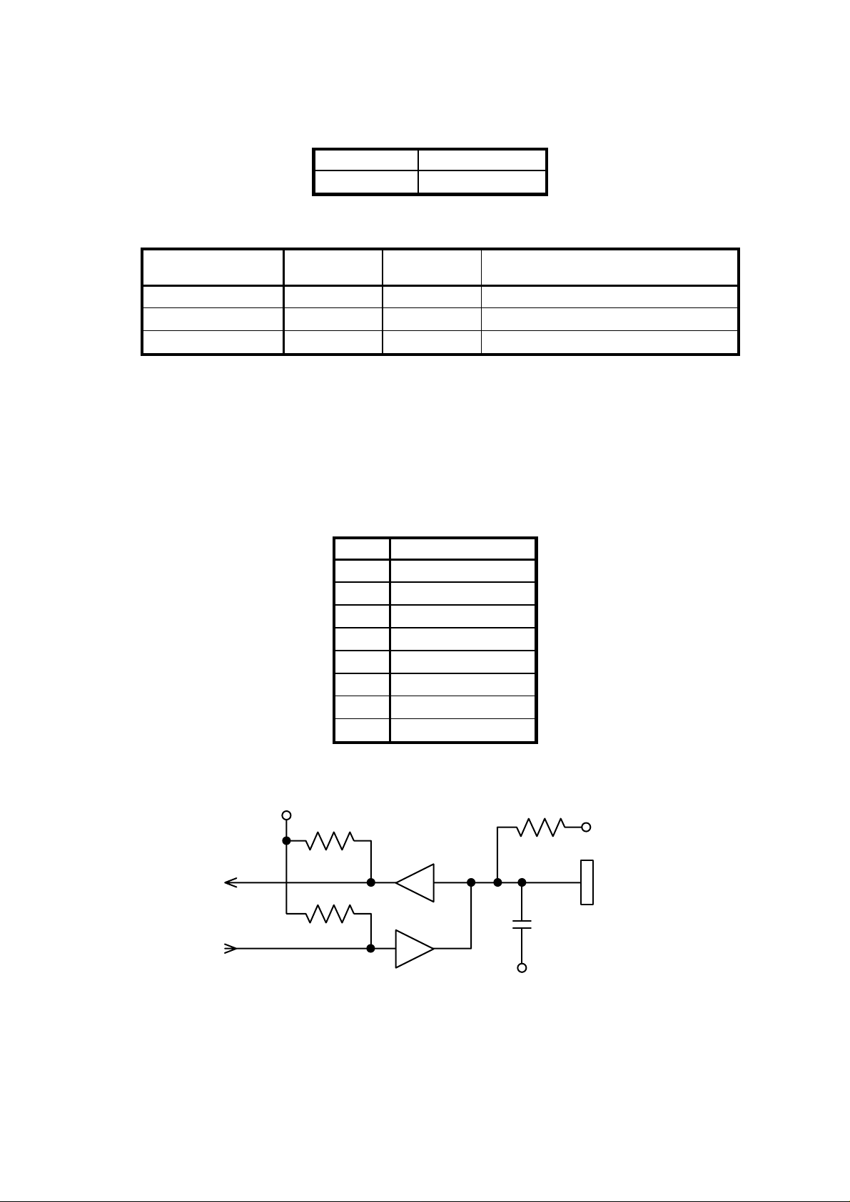
2) Interface circuit
5V
5V
Connector
0V
74LS07 or equivalent
I-2
Page 6
CHAPTER II MECHANICAL SYSTEM
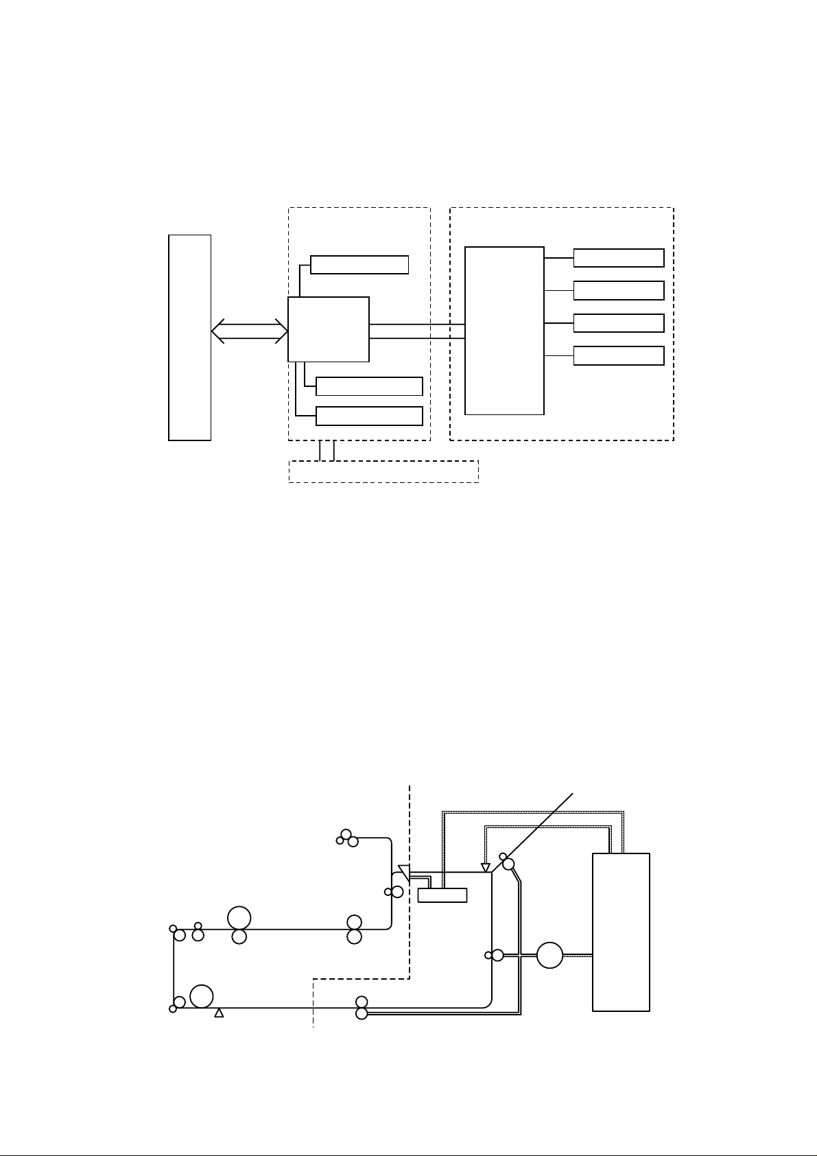
1. BLOCK DIAGRAM
The Duplex unit is composed of an outside frame, an inside frame and a Duplex tray, and
operates according to signals sent from the printer in serial communication.
Inside frame Outside frame
Printer
Serial
communication
Open cover sensor
I/F PCB
Paper pressure motor
Cassette sensor
Duplex tray
2. PAPER FEED MECHANISM
As soon as the printer requests for drive, a signal from the main PCB turns on the
solenoid to run the reversible motor clockwise (when viewed from the motor output shaft).
The Duplex unit will draw paper from the printer by turning on the solenoid.
The supplied paper is further transferred by the reversible motor driven reversible gears.
Figure 2.1
Main PCB
Fan motor
Reversible motor
Reverse sensor
Solenoid
When the reverse sensor detects the rear end of the paper, the reversible motor comes
to a momentary stop, and begins running counterclockwise.
Then the reversible motor enables the carriage rollers to feed the paper into the Duplex
tray installed within the Duplex unit. With the printer’s Duplex sensor on, the Duplex unit
stops the reversible motor by a request from the printer.
One cycle of paper feeding operation is completed in this way.
Duplex unitPrinter
Photosensitive drum
Pick up roller
Duplex sensor
Positioner
Du carriage roller
Reverse
sensor
Solenoid
Reversible gear
Reversible
motor
Main PCB
Figure 2.2
II-1
Page 7
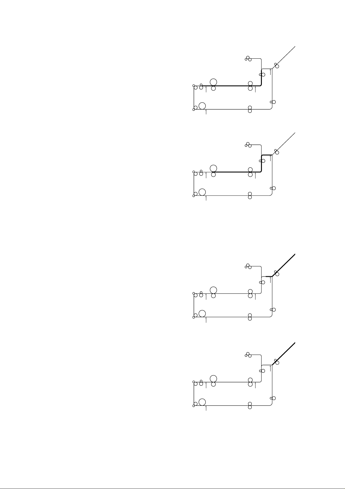
3. PAPER FEED SEQUENCE
(1) As soon as the printer requests for Duplex drive,
the solenoid is turned on, the flapper is switched,
and the motor runs forward.
(2) The reverse sensor is monitored to measure the
time from when the solenoid is turned on to when
the sensor is turned on.
If the sensor has not turned on after a specified
time passed, it is deemed that paper jam has
occurred.
(3) The solenoid is turned off in response to
instructions from the printer, and the flapper is
returned as it was before.
After the reverse sensor is turned on, the time up
to when the paper has passed through the reverse
sensor is monitored.
If the sensor has not turned off within a specified
time, it is deemed that paper jam has occurred.
(4) Immediately after the reverse sensor is turned off,
the motor begins through-down, stops for a
specified time, and runs backward.
II-2
Page 8
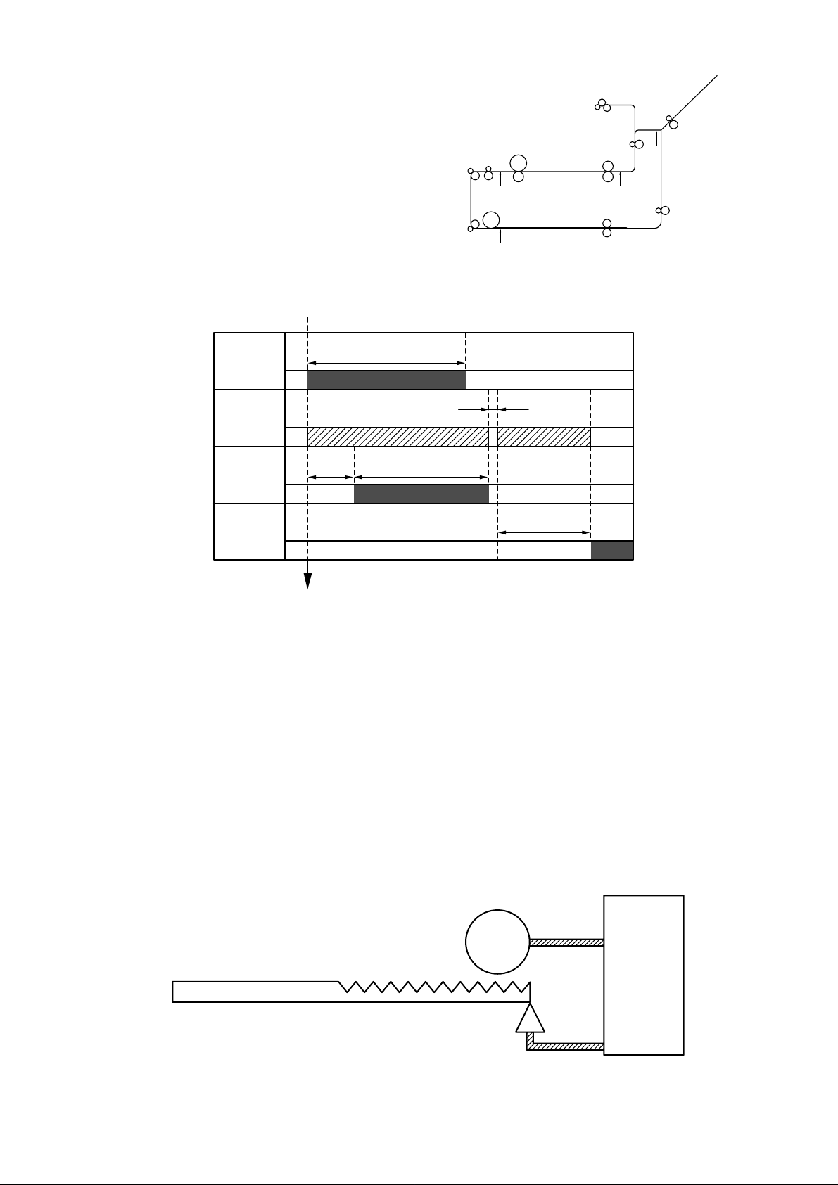
(5) As soon as the printer requests for stop, the motor
stops and goes into a standby state.
•• Paper Feed Timing Chart
(when only one piece of A4 paper is reversed and printing speed is 12 ppm)
Solenoid
Reversible
motor
Reverse
sensor
Duplex
sensor
Duplex drive request from the printer
1.3 sec* 4.21 sec*
4.84 sec*
C.W C.C.W
Figure 2.3
* The paper feed timing varys in the printing speed.
For 16 ppm, 12/16 times the above values.
For 20 ppm, 12/20 times the above values.
4. PAPER PRESSURE MECHANISM
Upon a request from the printer, the paper pressure unit built in the Duplex tray is moved
up or down by the paper pressure motor connected to the I/F PCB.
0.1 sec
3.2 sec*
The paper pressure unit is moved up only when the first tray is selected on the printer to
supply paper, or down when paper is fed from another tray.
The cassette sensor detects the position of the paper pressure unit, and whether the
Duplex tray is loaded into the Duplex unit.
Paper pressure motor
I/F PCB
Paper pressure unit
Cassette sensor
Figure 2.4
II-3
Page 9
CHAPTER III ELECTRICAL SYSTEM
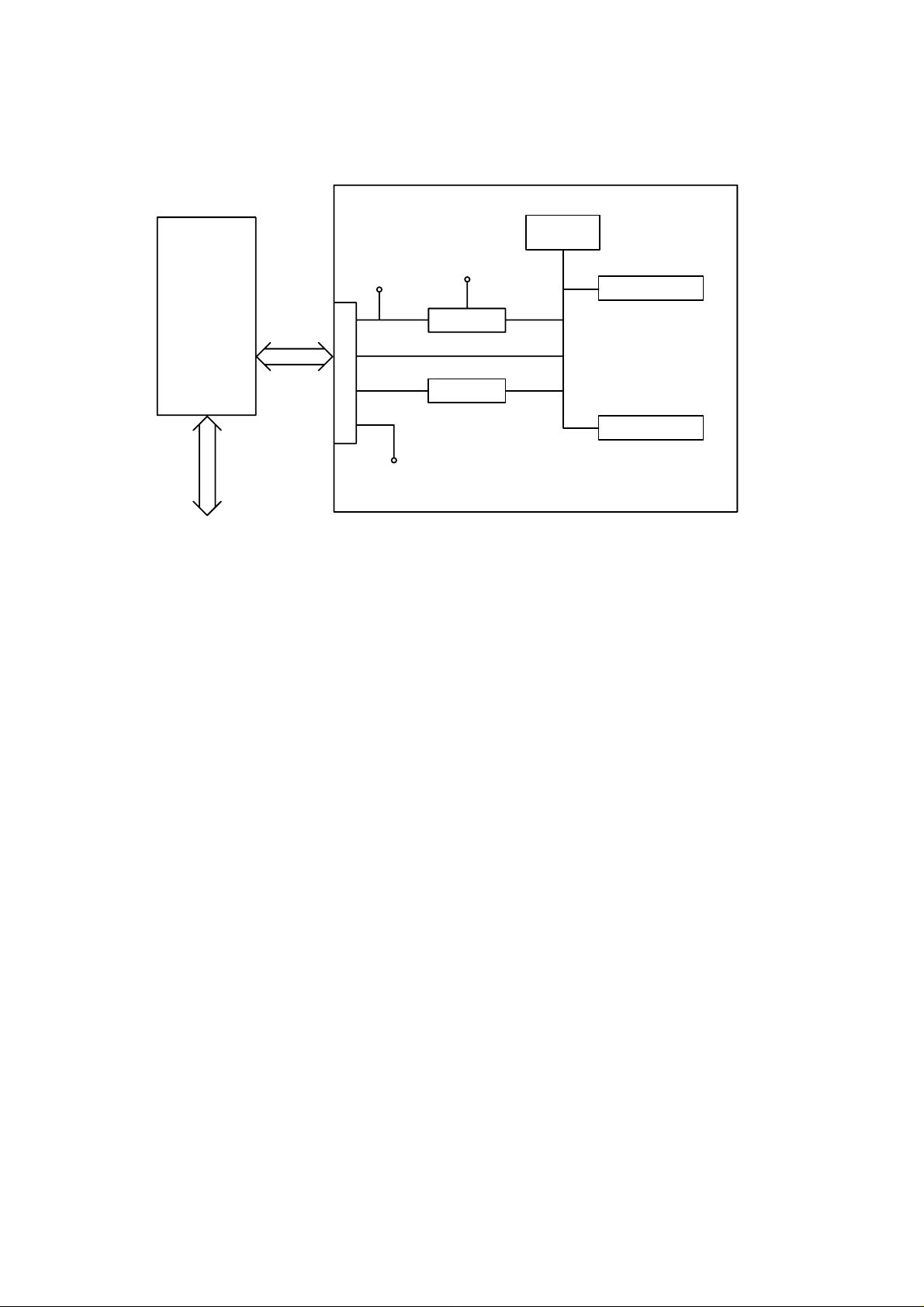
1. COMPOSITION
I/F PCB
Printer
2. MAIN PCB FUNCTION
2.1 I/F Circuit
+24V
Main PCB
CPU
M50927
+5V
Motor drive circuit
Regurator
I/F circuit
Fan drive circuit
GND
Figure 3.1
This interface circuit is used to transmit and receive data with the printer. Since the
Duplex unit responds only to commands from the printer, the Duplex unit transmits its
status upon request from the printer.
2.2 Regulator
The regulator produces +5V logic power supply from the +24V supplied by the printer.
2.3 Fan Drive Circuit
This circuit drives the cooling DC fan.
The fan rotation speed is switched between two different levels according to the signal
from the CPU. It operates at high speed when the Duplex unit feeds paper, or it runs at
low speed while the unit is not in operation.
When the DC fan functions properly, it sends a /FLOCK signal to the CPU to confirm that
it is normal.
2.4 Motor Drive Circuit
According to the signal from the CPU, this circuit drives both the reversible motor and the
paper pressure motor.
2.5 Solenoid Actuator
According to the signal from the CPU, this actuator turns the solenoid on or off.
2.6 Sensor Input
Signals to each of the reverse sensor, cassette sensor and open cover sensor are
imported to the CPU port.
III-1
Page 10
3. I/F PCB
The I/F PCB consists of two connectors (8-pin modular jack connectors) for connection of
the printer to other optional devices, a paper pressure motor, a cassette sensor, an open
cover sensor connector, and a connector for connection of the harness from the main
PCB.
This board only relays signals among the paper pressure motor, cassette sensor, open
cover sensor and printer and the main PCB.
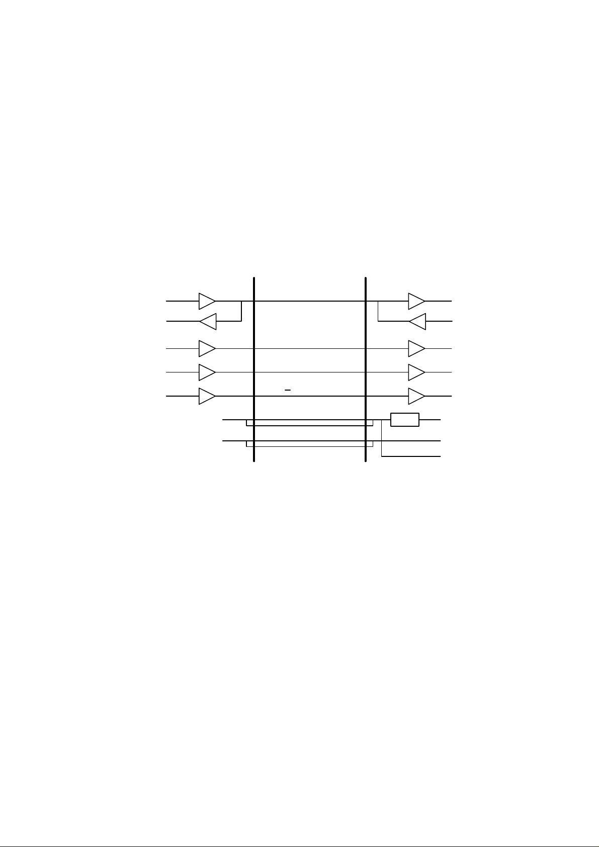
4. COMMUNICATION WITH THE PRINTER
A 3-line clock synchronous serial interface is used for communication between the
Duplex unit and the printer.
The following describe the timing of communication way.
Printer Duplex unit
DATAOUT
DATAIN
CLKOUT
/ATNOUT
/OPRST
+24V
GND
SIDATA
SICLK
/ATTN
/OP RESET
+24V
GND
Figure 3.2
REG.
DATAIN
DATAOUT
CLKIN
/ATNIN
/RESET
+5V
GND
+24V
III-2
Page 11
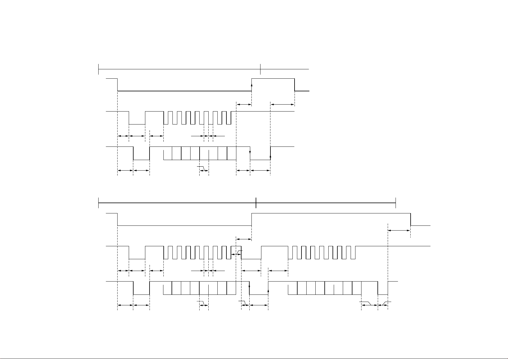
• Without a STATUS request
COMMAND transmission/receipt sequence
/ATTN
SICLK
500 min200 µs
III-3
400 min4µs
SIDATA
500 max
350 max
50 µs 12.8 µs
• Within a STATUS request
COMMAND transmission/receipt sequence
/ATTN
SICLK
400 min4µs
SIDATA
500 max
350 max
50 µs 350 max
6.4 min6.4 min
D0 D1 D2 D3 D4 D5 D6 D7
6.4 min
D0 D1 D2 D3 D4 D5 D6 D7
6.4 min
350 max
200 µs
350 max
200 µs
150 min
150 µs12.8 µs
STATUS transmission/receipt sequence
500 min
350 max
D0 D1 D2 D3 D4 D5 D6 D7
70 µs/1000 max 350 min
Page 12
CHAPTER IV DISASSEMBLY
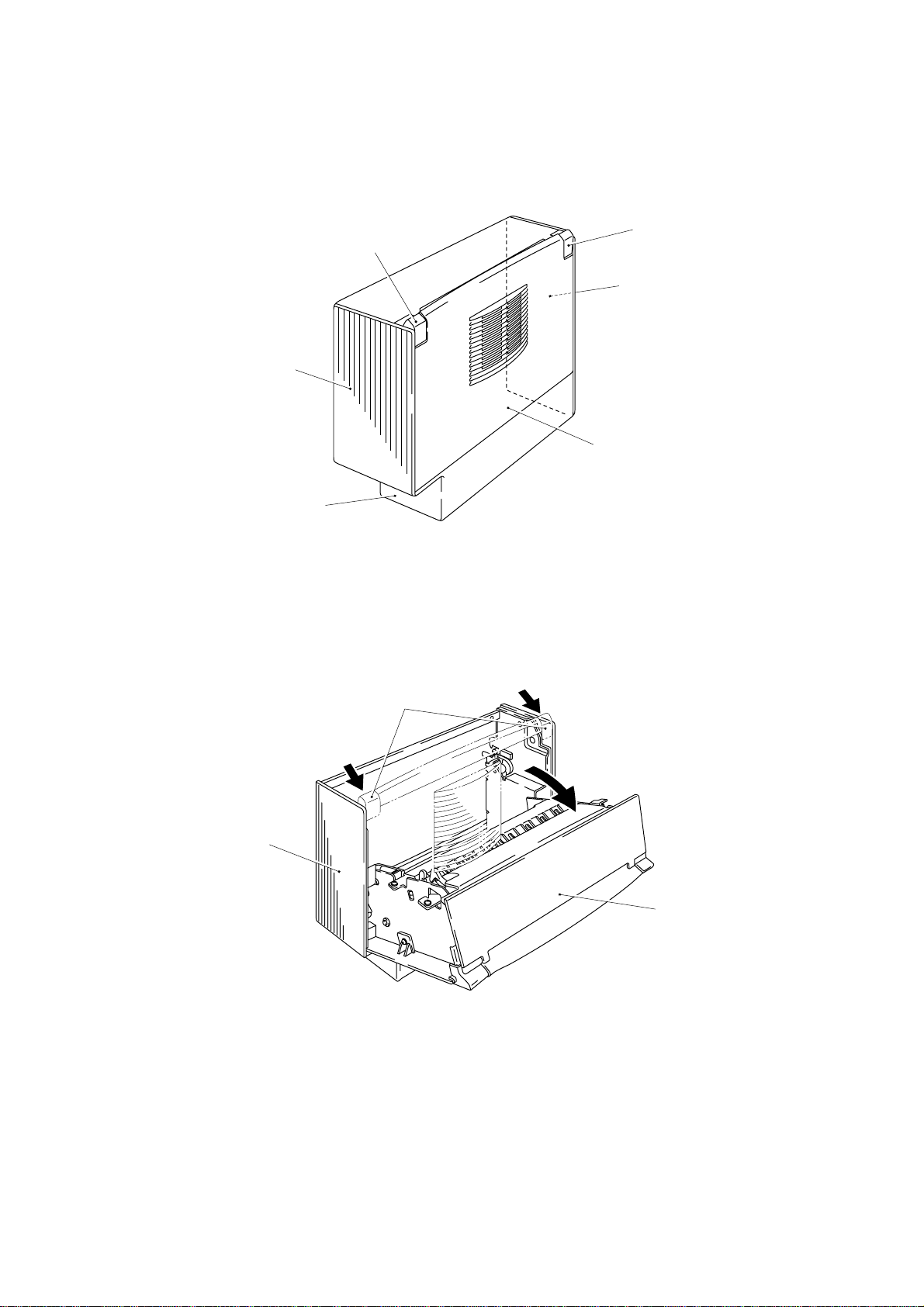
1. EXTERNAL COVERS
1.1 Composition
Side cover R
Bottom cover
1.2 Side Cover R
(1) Push the lock lever cover, turn and open the inside frame unit.
Lock lever cover
Lock lever cover
Side cover L
Top cover
Figure 4.1
Outside frame unit
Lock lever cover
Inside frame unit
Figure 4.2
IV-1
Page 13
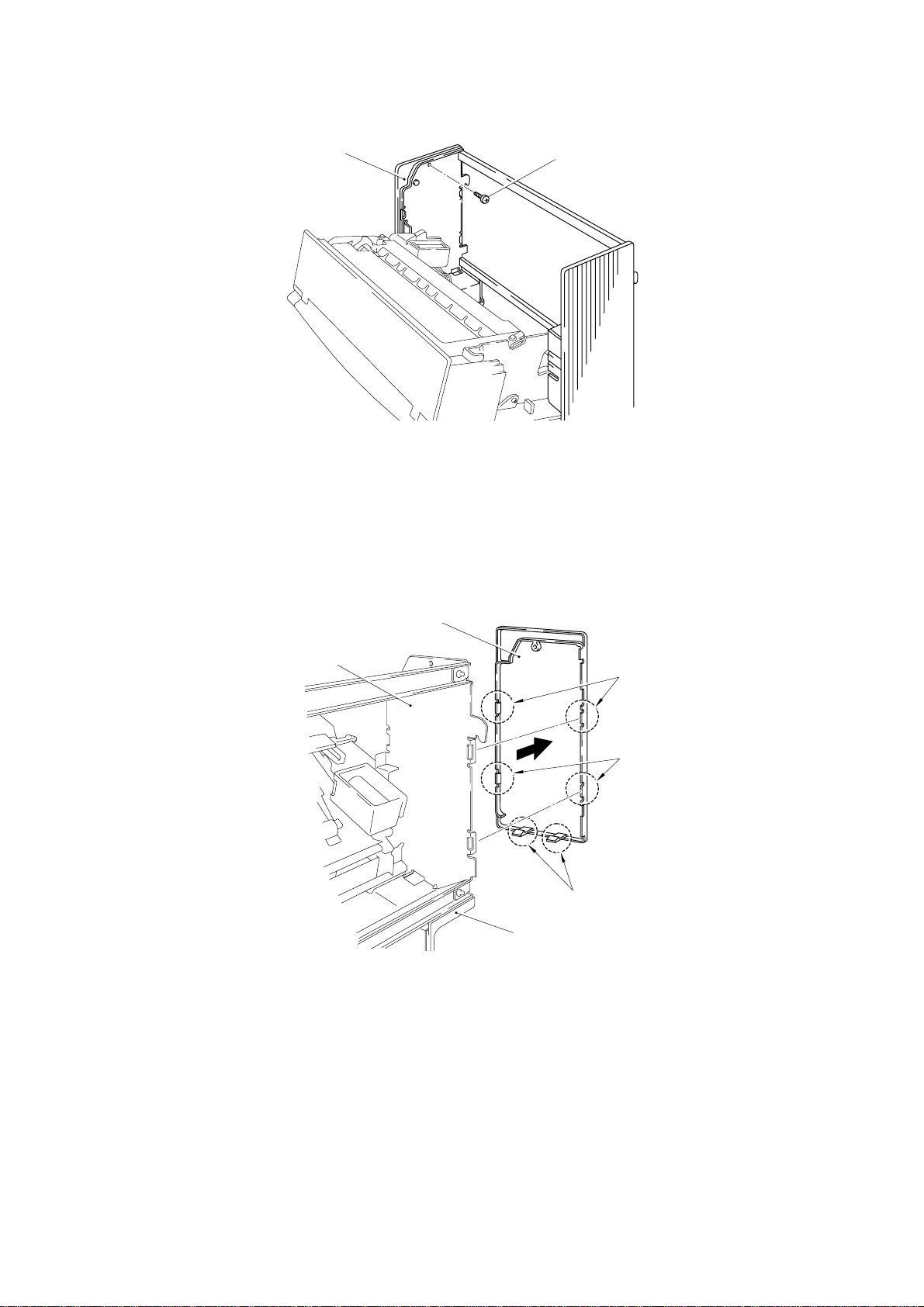
(2) Loosen the screw fastening the side cover R.
Side cover R
Taptite, bind B M3 x 6
Figure 4.3
(3) Using a small minus screwdriver, disengage the six hooks to remove the side
cover R from the outside frame R and the bottom cover.
(4) Separate the side cover R from the Duplex unit.
Outside frame R
Side cover R
Hooks
Hooks
Hooks
Bottom cover
Figure 4.4
IV-2
Page 14
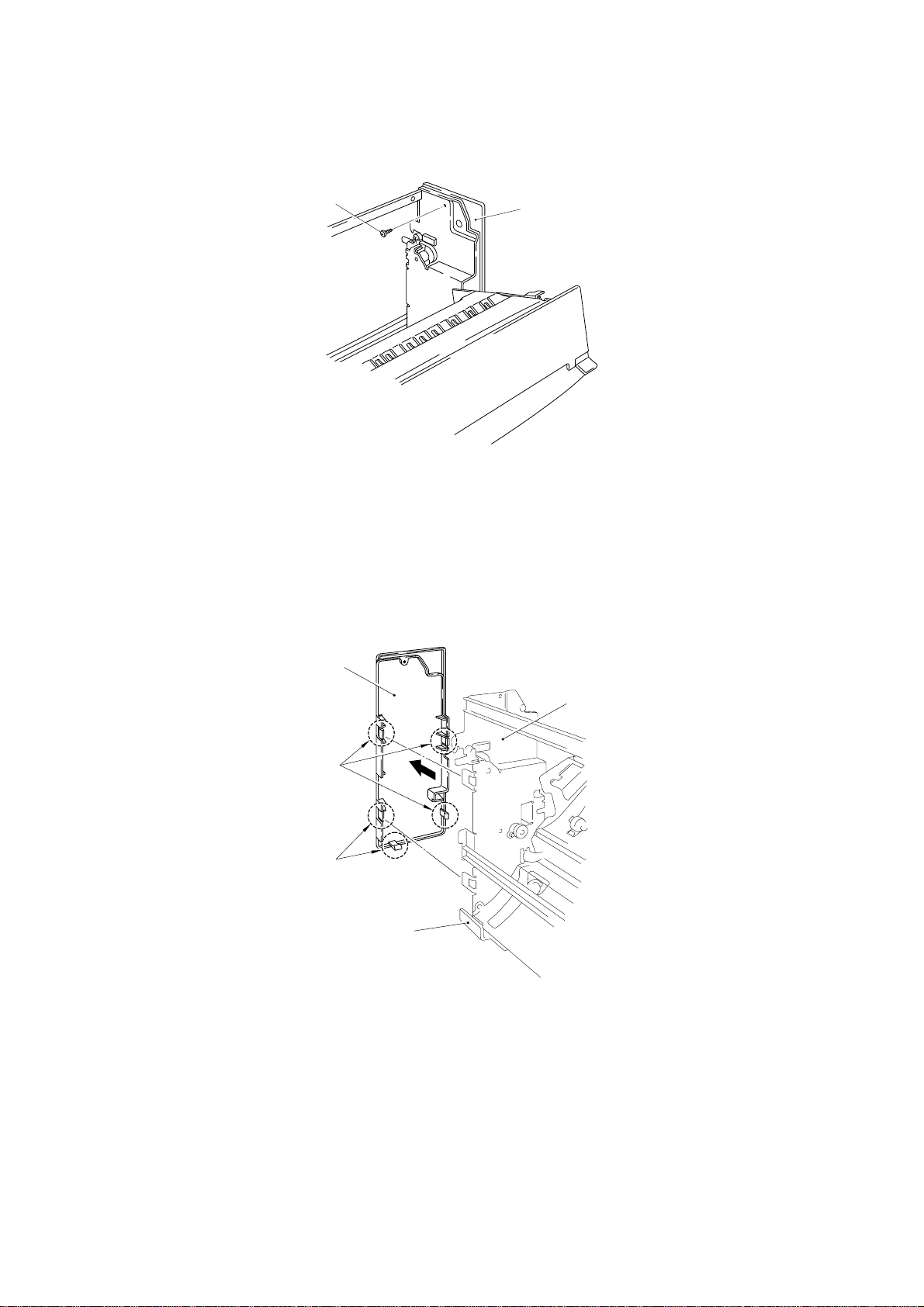
1.3 Side Cover L
(1) Unfasten the screw fastening the side cover L.
Taptite, bind B M3 x 6
Side cover L
Figure 4.5
(2) Using a small minus screwdriver, disengage the five hooks to remove the side
cover L from the outside frame L and the bottom cover.
(3) Separate the side cover L from the Duplex unit.
Side cover L
Hooks
Hooks
Outside frame L
Bottom cover
Figure 4.6
IV-3
Page 15
1.4 Bottom Cover
(1) Turn and close the inside frame unit.
(2) Lay down the Duplex unit on the side to face up the bottom cover.
(3) Loosen the two screws.
Bottom cover
Taptites, cup S M3 x 6
PR99079
Figure 4.7
(4) Disengage the engaging locks of the bottom cover from the outside frame L, and
separate the cover from the Duplex unit.
Bottom cover
Engaging locks
Figure 4.8
IV-4
Page 16
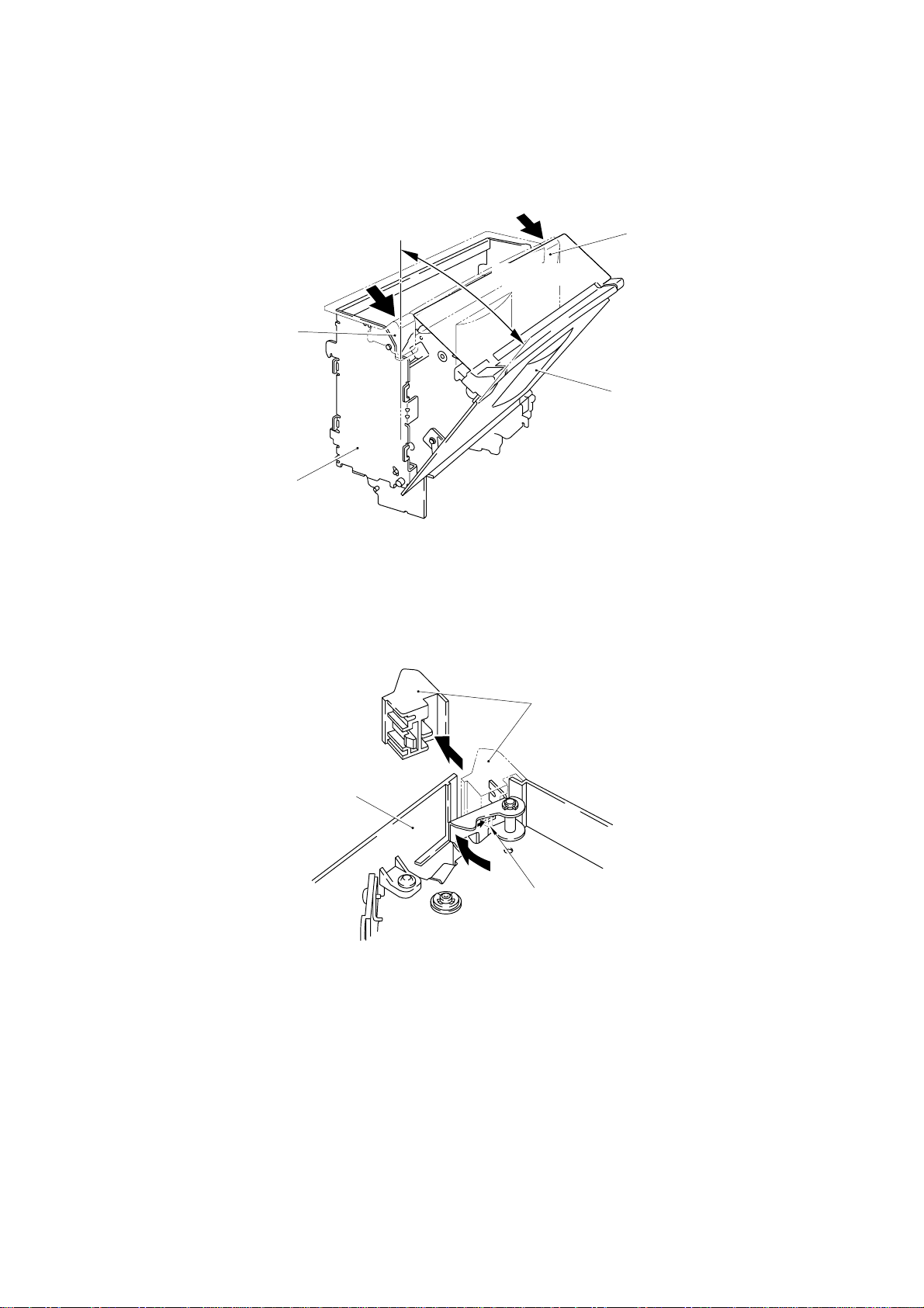
1.5 Top Cover
(1) Place the Duplex unit with the bottom down.
(2) Pushing the lock lever cover, turn and open the inside frame slightly. (approx.
30°)
Lock lever cover
Outside frame unit
Lock lever cover
Approx. 30°
Inside frame unit
Figure 4.9
(3) Disengage the hook of the lock lever cover by using a minus screwdriver, and pull
out the cover slantingly.
Lock lever cover
Top cover
Hook
Figure 4.10
IV-5
Page 17

(4) Loosen the four screws (two on each side).
g
Top cover
Taptites,
cup S M3 x 6
(5) Slide up the top cover to disengage the five engaging locks from the inside frame
unit, and separate the top cover from the Duplex unit.
Push the bosses in these holes,
and remove the
ear cover.
Top cover
Taptites,
cup S M3 x 6
Top cover
Figure 4.11
Gear cover
Engaging locks
Inside frame unit
Engaging locks
Figure 4.12
IV-6
Page 18

2. OUTSIDE FRAME UNIT
2.1 Composition
Outside frame R assy
Carriage guide 3
Paper pressure motor
Tower bars
Outside frame L assy
Figure 4.13
2.2.1 Removing the outside frame unit from the Duplex unit
(1) Turn and close the inside frame unit.
(2) Disconnect the relay harness assy from the Duplex I/F PCB assy and the edge
saddle.
(3) Pull out the fulcrum shaft R by using pliers.
(4) Remove the fulcrum spring.
Retaining ring E4
Retaining ring E6
Outside frame unit
Inside frame unit
Fulcrum shaft L
Fulcrum shaft R
Bearing collar
Fulcrum spring
Figure 4.14
IV-7
Page 19

Edge saddle
Relay harness assy
Duplex I/F PCB assy
Figure 4.15
(5) Slide the R side of inside frame unit toward you to remove it from the fulcrum
shaft L and the outside frame unit.
Inside frame unit
R side
Outside frame unit
Fulcrum shaft L
Figure 4.16
IV-8
Page 20

2.2.2 Mounting the outside frame unit in the Duplex unit
(1) Keeping the inside frame unit slantwise, mate the hole for the fulcrum shaft L of
the inside frame unit with the fulcrum shaft L.
Note1 : Do not get the relay harness assy caught between the inside
frame unit and the outside frame unit.
Note2 : If the solenoid assy harness is slack, stretch it.
(2) Turn the inside frame unit on the fulcrum shaft L to set it in the outside frame unit.
Solenoid assy harness
Solenoid
Outside frame unit
Inside frame unit
Hole for the fulcrum shaft L
Fulcrum shaft L
Figure 4.17
(3) Insert one end of the fulcrum spring in the hole in the outside frame unit.
Outside frame unit
Hole in the outside frame unit
Fulcrum spring
Relay harness assy
Inside frame unit
Figure 4.18
IV-9
Page 21

(4) Pass the fulcrum shaft R through the outside frame unit, the fulcrum spring and
the inside frame unit.
(5) Using nippers, set the other end of the fulcrum spring (inside frame unit side) in
the inside frame unit.
Outside frame unit
Retaining ring E6
2.3 Duplex I/F PCB
(1) Disconnect the paper pressure motor harness, the cover sensor harness assy
and the cassette sensor assy from the Duplex I/F PCB assy.
(2) Unfasten the screw.
(3) Remove the Duplex I/F PCB from the outside frame L.
Retaining ring E4
Fulcrum shaft R
Fulcrum spring
Figure 4.19
Inside frame unit
Bearing collar
Outside frame L
Taptite, cup S M3 x 5
Duplex I/F PCB
Cassette sensor assy
Cover sensor harness assy
Paper pressure motor harness
Figure 4.20
IV-10
Page 22

2.4 Outside Frame R Assy, L Assy
(1) Unfasten the four screws.
(2) Remove the two tower bars from the outside frame unit.
Taptites, cup S M3 x 5
(3) Unfasten the two screws.
(4) Remove the outside frame R assy from the carriage guide 3.
Tower bars
Taptite, cup S M3 x 5
Outside frame unit
Taptite, cup S M3 x 5
Figure 4.21
Outside frame R assy
Taptites, cup S M3 x 5
Carriage guide 3
Figure 4.22
IV-11
Page 23

(5) Unfasten the four screws.
(6) Remove the outside frame L assy and the paper pressure frame assy from the
carriage guide 3.
Taptites, cup S M3 x 5
Outside frame L assy
Carriage guide 3
Paper pressure frame assy
Taptites, cup S M3 x 5
Figure 4.23
2.5 Paper Pressing Gear 1, 2
(1) Remove the gear release spring from the paper pressure frame assy and the gear
release lever.
(2) Draw the paper pressure frame assy from the gear release lever in the direction
of the arrow.
(3) Remove the paper pressing gear 2.
Paper pressing gear 2
Gear release spring
Paper pressure frame assy
Gear release lever
Figure 4.24
IV-12
Page 24

(4) Remove the two retaining rings E3.
(5) Pull out the two paper pressing gear shafts.
(6) Remove the paper pressing gears 1 and 2.
Paper pressing gear 2
Gear release lever
Paper pressing gear shafts
2.6 Paper Pressure Motor
(1) Unfasten the screw A.
(2) Remove the cassette sensor lever and the leaf switch from the outside frame L
assy.
(3) Unfasten the two screws B.
Paper pressing gear 1
Retaining rings E3
Figure 4.25
(4) Remove the paper pressure motor from the outside frame L assy.
Paper pressure motor
Outside frame L assy
Leaf switch
Screw B (Taptite, bind S M3 x 5)
Cassette sensor lever
Screw A (Taptite, cup S M3 x 5)
Figure 4.26
Screw B (Taptite, bind S M3 x 5)
IV-13
Page 25

2.7 T Belt B40S2M396
(1) Remove the belt tension spring.
(2) Unfasten the screw.
(3) Remove the T belt B40S2M396.
Outside frame L assy
Taptite, cup S M3 x 5
T Belt B40S2M396
Belt tension spring
2.8 Photo Interrupter 1240
(1) Flexing the hook inward, turn the photo interrupter 1240 in the direction of the
arrow and remove it.
Photo interrupter 1240
Figure 4.27
Outside frame L assy
Hooks
Figure 4.28
IV-14
Page 26

3. INSIDE FRAME UNIT
3.1 Reversible Frame
(1) Unfasten the six screws.
(2) Remove the reversible frame.
Screws, pan
(S/P washer) M3 x 8
Switching guide
Reversible frame
Taptites, cup S M3 x 6
Inside frame unit
3.2 Photo interrupter 1240
(1) Disconnect the reverse sensor harness assy from the photo interrupter 1240.
(2) Flex the hooks of the photo interrupter 1240 to the inside to remove it.
Figure 4.29
Reverse sensor harness assy
Photo interrupter 1240
Hooks
Figure 4.30
IV-15
Page 27

3.3 Solenoid
y
(1) Remove the solenoid spring.
(2) Unfasten the two screws.
(3) Remove the solenoid.
(4) Detach the retaining ring E3.
(5) Remove the switch arm and the solenoid link.
Note1 : Since the solenoid assy harness is connected to the conductor,
handle it with care.
Note2 : Mount the solenoid without leaving the harness exposed
excessively.
Inside frame unit
Retaining ring E3
Switch arm
Solenoid link assy
Solenoid spring
Solenoid
3.4 Carriage Guide 2 Assy
(1) Unfasten the screw A and the screw B.
(2) Slide the carriage guide 2 assy slightly in the direction of the arrow, and
disengage the hooks.
(3) Remove the carriage guide 2 assy.
Note1 : When removing the carriage guide 2 assy, take care not to
damage the solenoid assy harness.
Hook
Screws, cup M3 x 5
Solenoid assy harness
Figure 4.31
Carriage guide 2 assy
Hook
(Taptite,
Screw A
cup S M3 x 5)
Figure 4.32
Solenoid ass
Washer
Screw B (Shoulder screw M3-4 x 4.4)
harness
IV-16
Page 28

3.5 Carriage Guide 1
(1) Slid the carriage guide 1 slightly in the direction of the arrow.
(2) Disengage the carriage guide 1 from the engaging locks of the inside frame assy.
(3) Slide up and remove the carriage guide 1.
Carriage guide 1
Engaging lock
Engaging lock
Inside frame unit
Figure 4.33
3.6 Duplex PCB Assy
(1) Disconnect the connectors of the solenoid, DC fan motor, reversible motor assy
and reverse sensor harness assy from the Duplex PCB assy.
(2) Detach the two retaining rings E3.
(3) Remove the two PF bearings 05.
(4) Remove the carriage roller assy.
Reversible motor assy
Retaining rings E3
PF bearing 05
DC fan motor
Duplex PCB assy
PF bearing 05
Retaining ring E3
Reverse sensor
harness assy
Solenoid
Carriage roller assy
Figure 4.34
IV-17
Page 29

(5) Unfasten the four screws.
(6) Remove the Duplex PCB assy.
Taptites, cup S M3 x 5
Duplex PCB assy
Taptites, cup S M3 x 5
Figure 4.35
3.7 DC Fan Motor
(1) Use a minus screwdriver to disengage the hook of the reversible gear 15-30, and
detach the gear.
(2) Detach the retaining ring E3.
(3) Remove the PF bearing 05.
(4) Remove the reversible gear assy.
Reversible gear 15-30
DC fan motor
PF bearing 05
Retaining ring E3
Reversible gear 15-30Hook
Reversible gear assy
Figure 4.36
IV-18
Page 30

(5) Unfasten the three screws.
,
y
(6) Remove the DC fan motor.
Note1 : The DC fan motor should be so mounted that the label will not be
Screws, pan (washer)
M3 x 29.5
exposed.
Screw, pan (washer)
M3 x 29.5
DC fan motor
3.8 Reversible Motor Assy
(1) Unfasten the two screws.
(2) Remove the reversible motor assy.
Figure 4.37
Figure 4.38
Reversible motor ass
Screws
cup M4 x 6
IV-19
Page 31

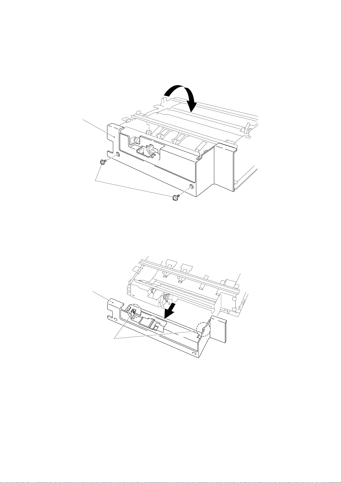
4. DU TRAY CARRYING WAY UNIT
(1) Unfasten the screw on the back of unit.
Taptite, bind B M3 x 6
DU tray carrying way
Roller
Figure 4.39
(2) Turn the unit to the face and remove the pressure roller.
DU tray carrying way
Pressure roller
Figure 4.40
IV-20
Page 32

(3) Unfasten the three screws.
Taptite, bind B M3 x 6
Carriage guide 4
Figure 4.41
(4) Remove the four hooks on the back of unit and carriage guide 4.
Hook
Hook
Hook
Carriage guide 4
Hook
DU tray carrying way
Figure 4.42
Figure 4.43
IV-21
Page 33

Front ground spring
(5) Remove the tray pulley gear shaft from the clamp.
Note1 : Take care not to come off the rear ground spring.
When reassembling the rear ground spring, put it in the locating boss.
Rear ground spring
Locating boss
Figure 4.44
Paper pressure plate
DU tray carrying way
T Belt B40S2M396
Tray pulley gear
Clamp
Figure 4.45
IV-22
Page 34

(6) Remove the paper pressure fulcrum shaft from the two clamps.
Paper pressure 1
Paper pressure 2 assy
Paper pressure fulcrum shaft
DU tray carrying way
Clamps
Figure 4.46
(7) Remove the roller assy from the clamp.
Clamp
Figure 4.47
Roller assy
IV-23
Page 35

(8) Remove the discharge brush.
Discharge brush
Front ground spring
Clamps
Figure 4.48
IV-24
Page 36

Troubleshooting (1)
Problem Cause Check Result Remedy
CHAPTER V TROUBLESHOOTING
V-1
be set on the panel.
message appears.
appears.
MisoperationThe Duplex mode cannot
Modular cable
Main PCB
Misoperation“NO DX TRAY” error
Main PCB Does a voltage of 24V appear at pins 3
Paper pressure
motor
Misoperation“DX OPEN” error message
Open cover sensor
Main PCB
Is the modular cable connected properly? No Turn off the power to the printer, and connect
Does a voltage of 24V appear at pin 14 or
15 of I/F PCB’s connector P4?
Is the Duplex tray loaded properly into the
cassette according to the manual?
and 4 of I/F PCB’s connector P3, and does
the voltage vary from 0V to 24V at pins 1,
2, 5 and 6 when the paper cassette is set?
Does the paper pressure motor run when
the paper cassette is set?
Is the hook of the Duplex unit’s reversing
mechanism engaged completely with the
outside frame?
Does a voltage of 5V appear at pin 3 of I/F
PCB’s connector P1 when the cover is
closed?
the modular cable properly. Then, turn on the
power again.
Yes Replace the main PCB.
No
No Load the Duplex tray into the cassette according
No Replace the main PCB.
No Replace the paper pressure motor.
Yes Replace the cassette sensor lever and
No Close the reversing mechanism so as to engage
No Replace the open cover sensor or cover sensor
Yes Replace the main PCB.
Replace the modular cable.
to the manual.
leaf switch. Refer to Figure 4.26 (IV-9).
the hook securely with the outside frame.
harness.
message apprears.
Main PCB“DX FAN MALF” error
Fan
Main PCB
Does a voltage of more than15V appear
at pin 1 of main PCB’s connector P1?
Is the voltage 0V at pin 2 of main PCB’s
connector P1?
No Replace the main PCB.
No Replace the fan.
Yes Replace the main PCB.
Page 37

Troubleshooting (2)
Problem Cause Check Result Remedy
V-2
the Duplex unit.
"JAM DUPLEX" error
message appears though
no paper is supplied in the
Duplex unit.
The paper supplied in the
Duplex unit stops halfway.
"JAM TRAY" error
message appears.
The first or second sheet of
paper is not supplied to the
HL-1260 resist sensor.
MisoperationPaper is not supplied in
Main PCB Does the voltage vary from 24V to 0V at
Solenoid Does the solenoid function? No Replace the solenoid.
Main PCB Does the voltage vary from 24V to 0V at
Reversible motor Does the reversible motor run? No Replace the reversible motor.
Switching guide Does the switching guide move smoothly?
Main PCB
Reverse sensor
DU detection
(HL-1660/2060)
HL-1660/2060 unit
Pickup roller
(HL-1660/2060)
Duplex tray
Is the Duplex unit set properly in the
printer?
pin 2 of main PCBÕs connector P2?
pins 1, 2, 3 and 4 of main PCB's
connector P6?
Refer to Figure 4.29 (IV-11).
Does the voltage vary from 5V to 0V at pin
3 of main PCB's connector P5 while the
switching guide is moving?
Does the actuator (Parts reference list,
11-20) move smoothly?
Supply paper in Simplex mode.
Is paper correctly supplied?
No Set the Duplex unit properly according to the
manual.
No Replace the main PCB.
No Replace the main PCB.
No Reset the switching guide, or replace its parts.
No Replace the reverse sensor or reverse sensor
harness.
Yes Replace the main PCB.
No Replace the HL-1660/2060 actuator.
No Repair the HL-1260 unit.
(Pickup mistake with the first sheet of paper)
Yes Set the Duplex tray correctly.
1
2
Set the HL-1660/2060 pickup roller correctly.
(Pickup mistake with the second sheet of paper)
Page 38

Appendix 1. Connection Diagram
A-1
Page 39

Appendix 2. Motor Drive Circuit
A-2
Page 40

Appendix 3. Main PCB Circuitry Diagram
A-3
Page 41

July, ’98
54T047NE0-DX-2000
Page 42

R
DUPLEX UNIT
PARTS REFERENCE LIST
MODEL:DX-2000
Page 43

NOTE FOR USING THIS PARTS REFERENCE LIST
1. In the case of ordering parts, it needs mentioning the following items:
(1) Code
(2) Q'ty
(3) Description
(4) Symbol ( PCB No., Revision , and Parts location mounted on the PCB.)
Note : No orders without Parts Code or Tool No. can be accepted.
< Example >
(1)
REF.NO. CODE Q’TY DESCRIPTION SYMBOL REMARK
Revision No.: marked on the printed circuit board.
(2)
(3)
(4)
B48K056 - 201A
Design change indication
Specification No .
Pattern alteration No.
Circuit board No.
2. Design-changed parts :
If the parts are changed, any one of the following symbols is indicated in the REMARKS
column.
#A : compatible between old and new
#B : replaceable from old to new
#D : incompatible
# : newly established
3. The original of this list was made based on the information available in November, 1997.
4. Parts are subject to change in design without prior notice.
Page 44

CONTENTS
1. INSIDE FRAME UNIT ...........................................................................1
2. OUTSIDE FRAME UNIT .......................................................................1
3. MAIN PCB.............................................................................................3
4. COVERS...............................................................................................3
5. TRAY CARRYING UNIT .......................................................................5
6. PAPER TRAY .......................................................................................5
7. DOCUMENTS & ATTACHMENTS........................................................7
8. PACKING MATERIALS.........................................................................7
Page 45

1. INSIDE FRAME UNIT
3
4
1
2
6
5
2
8
7
MODEL DX-2000 54T-X10-510
2. OUTSIDE FRAME UNIT
2
3
7
6
5
4
8
1
-1-
MODEL DX-2000 54T-X10-550
Page 46

1. INSIDE FRAME UNIT
REF.NO. CODE Q'TY DESCRIPTION REMARK
1 UH2124001 1 DC FAN MOTOR
2 UJ3415001 2 SCREW, PAN(P WASHER) M3X29.5
3 UH3726001 1 REVERSING MOTOR 55 ASSY 2
4 UF4444001 2 SCREW, PAN(P WASHER) M4X6
5 UH1707001 1 SOLENOID ASSY
6 U50553001 2 SCREW, CUP M3X5
7 UJ4232000 1 PHOTO INTERRUPTER:1240
8 UH1732001 1 REVERSE SENSOR HARNESS ASSY
MODEL DX-2000 54T-X10-510
2. OUTSIDE FRAME UNIT
REF.NO. CODE Q'TY DESCRIPTION REMARK
1 UH1655001 1 T BELT, B40S2M396
2 Z25996001 1 MOTOR, BP484223LM31-FD
3 085320515 2 TAPTITE, BIND S M3X5
4 UH1734001 1 CASSETTE SENSOR ASSY
5 UH1751000 1 CASSETTE SENSOR LEVER
6 UJ4232000 1 PHOTO INTERRUPTER:1240
7 UH1733001 1 COVER SENSOR HARNESS ASSY
8 UH1786001 1 P PRESSURE MOTOR HARNESS ASSY
- 2 -
MODEL DX-2000 54T-X10-550
Page 47

3 . MAIN PCB
2
1
4
2
3
T/I No. PR99027
2
9
MODEL DX-2000 54T-X10-100
4 . COVERS
9
1
2
8
6
7
10
5
-3-
3
4
MODEL DX-2000 54T-X10-400
Page 48

3. MAIN PCB PR99027
REF.NO. CODE Q'TY DESCRIPTION SYMBOL REMARK
1 UK4106001 1 MAIN PCB ASSY, DX-2000 B48K264-2A CHG REV.
2 087320516 4 TAPTITE, CUP S M3X5
3 UK4108001 1 DUPLEX IF PCB ASSY, DX-2000 B48K265-1
4 087320516 1 TAPTITE, CUP S M3X5
MODEL DX-2000 54T-X10-100
4. COVERS
REF.NO. CODE Q'TY DESCRIPTION REMARK
1 UH1667001 1 TOP COVER
2 087320616 4 TAPTITE, CUP S M3X6
3 UH1668001 1 BOTTOM COVER
4 087320616 2 TAPTITE, CUP S M3X6
5 UH1669001 1 SIDE COVER L
6 085310616 1 TAPTITE, BIND B M3X6
7 UH1670001 1 SIDE COVER R
8 085310616 1 TAPTITE, BIND B M3X6
9 UH1671001 2 LOCK LEVER COVER
10 UH1770001 1 GEAR COVER
- 4 -
MODEL DX-2000 54T-X10-400
Page 49

5 . TRAY CARRYING UNIT
1
MODEL DX-2000 54T-X10-610
6 . PAPER TRAY
5
1-7
6
1
3
2
4
7
MODEL DX-2000 54T-X10-650
-5-
Page 50

5. TRAY CARRYING UNIT
REF.NO. CODE Q'TY DESCRIPTION REMARK
1 UH2035001 1 DU TRAY CARRYING WAY UNIT 2
MODEL DX-2000 54T-X10-610
6. PAPER TRAY
REF.NO. CODE Q'TY DESCRIPTION REMARK
1 - 7 UH3162001 1 PAPER TRAY S UNIT DX3 (SP)
1 UH2487001 1 SEPARATION PAD ASSY T
2 UH2841001 1 SEPARATION PAD SPRING 200
3 UH2360000 1 ROLLER
4 UH2459000 1 ROLLER HOLDER
5 UH1776001 1 PAPER FRONT GUIDE DU, BLUE6155
6 UH2472001 1 TRAY GUIDE PLATE 1
7 UH2804001 1 ADJUST KNOB STOPPER
- 6 -
MODEL DX-2000 54T-X10-650
Page 51

7 . DOCUMENTS & ATTACHMENTS
1
4
2
3
MODEL DX-2000 54T-X10-910
8 . PACKING MATERIALS
1
2
4
2
R
3
-7-
MODEL DX-2000 54T-X10-930
Page 52

7. DOCUMENTS & ATTACHMENTS
REF.NO. CODE Q'TY DESCRIPTION REMARK
1 UH3728001 1 USER'S GUIDE, DX-2000
2 UH1735001 1 MODULAR CORD 8PDX
3 UH2440001 1 PAPER FEED ROLLER ASSY DU2
4 UH2439001 1 INSERTION SHEET
MODEL DX-2000 54T-X10-910
8. PACKING MATERIALS
REF.NO. CODE Q'TY DESCRIPTION REMARK
1 UE0694001 1 CARTON, DX-2000
1 UE0695001 1 CARTON, DX-2000 BROTHER
2 UE0457000 1 STYROFOAM PAD ASSY
3 UE0454000 1 CARTON ,TRAY
4 UE1109001 1 PE BAG, 215X290H
- 8 -
MODEL DX-2000 54T-X10-930
Page 53

July, ’98
54T048NE0-DX-2000
 Loading...