

Page 1
SERVICE MANUAL FOR
COMPUTERIZED SEWING MACHINE
LOW-END COMPUTER SERIES
CS4000
BC2100
BC2300
RS240
RS250
ES2000
ES2000t
ES2200
ES2010
ES2210
ES2020
ES2220
comfort40E
CE4000
CS6000
CS6000b
CS6000t
CS6000i
BC2500
RS260
XR7700
ES2400
ES2410
ES2420
comfort60E
CS100t
EX-660
BC1000
HS1000
The CD-ROM version of service manual contains movie!
CD-ROM version of service manual contains movies "2. Disassembly"
"3. Assembly".Please click on mark to start the movie.
10.2005.
6.2007.
Page 2
Page 3

1. Outline of Mechanism ........................................................................1 - 1
Main Mechanisms ...........................................................................1 - 2
Driveline ..........................................................................................1 - 3
Positions of electronic components ...................................................................1 - 4
Control system block diagram ...........................................................................1 - 5
Control system block diagram ...........................................................................1 - 6
Operation of other electronic components .........................................................1 - 7
2. Disassembly ........................................................................................2 - 1
Main parts ..........................................................................................................2 - 2
Accessory table removal ....................................................................................................................2 - 3
Bottom cover removal .......................................................................................................................2 - 3
Needle plate B assembly removal ......................................................................................................2 - 4
Needle plate B ASSY disassembly ..............................................................................................2 - 4
Face plate assembly removal .............................................................................................................2 - 5
Face plate A ASSY disassembly .................................................................................................2 - 5
Front cover removal ...........................................................................................................................2 - 6
Thread tension holder assembly and thread take-up holder B removal .............................................2 - 7
Thread tension holder ASSY disassembly ..................................................................................2 - 7
Thread take-up holder B disassembly ...........................................................................................2 - 8
LED lamp removal .............................................................................................................................2 - 8
Operation PCB assembly and SSVR PCB assembly removal ...........................................................2 - 9
Button removal ..................................................................................................................................2 - 9
Front panel and LCD removal ...........................................................................................................2 - 9
SV keytop removal ..........................................................................................................................2 - 10
Base plate rubber removal ...............................................................................................................2 - 10
Upper cover thread guide removal ...................................................................................................2 - 10
Main PCB assembly removal ..........................................................................................................2 - 11
Main PCB ASSY disassembly ...................................................................................................2 - 11
Power PCB assembly removal .........................................................................................................2 - 12
Power PCB ASSY disassembly ................................................................................................2 - 12
Inlet assembly removal ....................................................................................................................2 - 12
FC jack removal ...............................................................................................................................2 - 13
Main motor assembly removal ........................................................................................................2 - 13
Main motor ASSY disassembly ................................................................................................2 - 13
Tension pulley assembly removal ....................................................................................................2 - 14
Tension pulley ASSY disassembly ............................................................................................2 - 14
Feed unit assembly removal ...........................................................................................................2 - 14
Upper shaft assembly removal .........................................................................................................2 - 15
Needle-presser unit removal ............................................................................................................2 - 15
Plate spring removal ........................................................................................................................2 - 15
Bobbin base assembly removal ........................................................................................................2 - 16
Bobbin base ASSY disassembly ................................................................................................2 - 16
Bobbin winder assembly removal ....................................................................................................2 - 16
Spool pin removal ............................................................................................................................2 - 17
Bobbin presser removal ...................................................................................................................2 - 17
Thread guide assembly removal ......................................................................................................2 - 17
Base plate rubber removal ...............................................................................................................2 - 18
Feed unit ..........................................................................................................2 - 19
Needle plate A assembly removal ...................................................................................................2 - 20
i
Page 4

Needle plate A ASSY disassembly ...........................................................................................2 - 20
Spring removal .................................................................................................................................2 - 20
Inner rotary hook bracket assembly removal ...................................................................................2 - 20
Feed dog removal .............................................................................................................................2 - 21
Vertical adjuster screw assembly removal .......................................................................................2 - 21
Outer rotary hook removal ...............................................................................................................2 - 21
Shaft supporter removal ...................................................................................................................2 - 21
Feed bar removal .............................................................................................................................2 - 22
Needle plate supporter shaft B removal ...........................................................................................2 - 22
Feed arm A assembly removal .........................................................................................................2 - 23
Feed arm B ASSY disassembly ................................................................................................2 - 23
Feed adjuster assembly removal ......................................................................................................2 - 24
Feed adjuster disassembly .........................................................................................................2 - 24
Vertical lever removal .....................................................................................................................2 - 24
FPM holder assembly removal ........................................................................................................2 - 25
FPM disassembly .......................................................................................................................2 - 25
Timing pulley D removal .................................................................................................................2 - 25
Lower shaft assembly removal ........................................................................................................2 - 26
Lower shaft bushing removal ..........................................................................................................2 - 26
Needle-presser unit .........................................................................................2 - 27
Threader hook assembly .................................................................................................................2 - 28
LED lamp left assembly removal ....................................................................................................2 - 28
BH switch assembly removal ..........................................................................................................2 - 28
Thread take-up lever and needle bar crank removal ........................................................................2 - 28
Thread take-up lever link removal ...................................................................................................2 - 29
Needle bar assembly removal ..........................................................................................................2 - 29
Needle bar ASSY disassembly ...................................................................................................2 - 29
Needle holder assembly removal .....................................................................................................2 - 30
Needle holder ASSY disassembly .............................................................................................2 - 31
Presser bar removal ..........................................................................................................................2 - 32
Z zigzag lever assembly removal .....................................................................................................2 - 32
Z zigzag lever disassembly .......................................................................................................2 - 33
Z zigzag camp removal ....................................................................................................................2 - 33
Shaft bushing removal .....................................................................................................................2 - 33
Presser foot lifter removal ................................................................................................................2 - 33
Thread release lever removal ...........................................................................................................2 - 34
Lock nut removal .............................................................................................................................2 - 34
Z pulse motor removal .....................................................................................................................2 - 34
Presser switch assembly removal ....................................................................................................2 - 34
3. Assembly .............................................................................................3 - 1
Main parts ..........................................................................................................3 - 2
Base plate rubber attachment .............................................................................................................3 - 3
Thread guide assembly attachment ....................................................................................................3 - 3
Bobbin presser attachment .................................................................................................................3 - 3
Spool pin attachment .........................................................................................................................3 - 4
Bobbin winder assembly attachment .................................................................................................3 - 5
Bobbin base assembly attachment .....................................................................................................3 - 6
Bobbin base ASSY assembly .......................................................................................................3 - 6
Plate spring attachment ......................................................................................................................3 - 6
Needle-presser unit attachment ..........................................................................................................3 - 7
Upper shaft assembly attachment ......................................................................................................3 - 8
Feed unit assembly attachment ..........................................................................................................3 - 9
Upper shaft and lower shat phase matching ......................................................................................3 - 9
Tension pulley assembly attachment ...............................................................................................3 - 10
ii
Page 5

Tension pulley ASSY assembly ................................................................................................3 - 10
Main motor assembly attachment ....................................................................................................3 - 10
Main motor assembly .................................................................................................................3 - 10
FC jack attachment ..........................................................................................................................3 - 11
Inlet assembly attachment ................................................................................................................3 - 11
Power PCB assembly attachment ....................................................................................................3 - 12
Power PCB ASSY assembly .....................................................................................................3 - 12
Main PCB assembly attachment ......................................................................................................3 - 13
Main PCB assembly ..................................................................................................................3 - 13
Upper cover thread guide attachment ..............................................................................................3 - 13
Base plate rubber attachment ...........................................................................................................3 - 14
SV keytop attachment ......................................................................................................................3 - 14
Front panel LCD attachment ............................................................................................................3 - 14
Button attachment ............................................................................................................................3 - 15
Operation PCB assembly and SSVR PCB assembly attachment ....................................................3 - 15
LED lamp attachment ......................................................................................................................3 - 16
Thread tension holder assembly and thread take-up holder B attachment ......................................3 - 16
Thread tension holder ASSY assembly .....................................................................................3 - 16
Thread take-up holder B assembly..............................................................................................3 - 17
Front cover attachment ....................................................................................................................3 - 18
Face plate A assembly attachment ...................................................................................................3 - 19
Face plate A ASSY assembly ...................................................................................................3 - 19
Needle plate B assembly attachment ...............................................................................................3 - 20
Needle plate B ASSY assembly .................................................................................................3 - 20
Base cover attachment .....................................................................................................................3 - 20
Accessory table attachment .............................................................................................................3 - 21
Feed unit ..........................................................................................................3 - 22
Lower shaft bushing attachment ......................................................................................................3 - 23
Lower shaft assembly attachment ....................................................................................................3 - 23
Timing pulley D attachment ............................................................................................................3 - 23
FPM holder assembly attachment ....................................................................................................3 - 24
FPM assembly ...........................................................................................................................3 - 24
Vertical lever attachment .................................................................................................................3 - 25
Feed adjuster assembly attachment ..................................................................................................3 - 26
Feed adjuster ASSY assembly ...................................................................................................3 - 26
Feed arm A assembly attachment ....................................................................................................3 - 27
Feed arm B ASSY assembly ......................................................................................................3 - 28
Needle plate supporter shaft B attachment ......................................................................................3 - 29
FPM gear engagement .....................................................................................................................3 - 30
Feed bar attachment .........................................................................................................................3 - 31
Shaft supporter attachment ..............................................................................................................3 - 31
Outer rotary hook attachment ..........................................................................................................3 - 32
Vertical adjuster screw assembly attachment ..................................................................................3 - 32
Feed dog attachment ........................................................................................................................3 - 32
Inner rotary hook bracket assembly attachment ..............................................................................3 - 33
Spring attachment ............................................................................................................................3 - 33
Needle plate A assembly attachment ...............................................................................................3 - 33
Needle plate A ASSY assembly ................................................................................................3 - 33
Needle-presser unit .........................................................................................3 - 34
Presser switch assembly attachment ................................................................................................3 - 35
Z pulse motor attachment ................................................................................................................3 - 35
Lock nut attachment .........................................................................................................................3 - 36
Thread release lever attachment ......................................................................................................3 - 36
Presser foot lifter attachment ...........................................................................................................3 - 37
Shaft bushing attachment .................................................................................................................3 - 37
iii
Page 6

Z zigzag cam attachment .................................................................................................................3 - 38
Z zigzag lever assembly attachment ................................................................................................3 - 39
Z zigzag lever ASSY assembly .................................................................................................3 - 39
Presser bar attachment .....................................................................................................................3 - 40
Needle holder assembly attachment ...............................................................................................3 - 41
Needle holder ASSY assembly .................................................................................................3 - 42
Needle bar assembly attachment ......................................................................................................3 - 43
Needle bar ASSY assembly .......................................................................................................3 - 43
Thread take-up lever link attachment ..............................................................................................3 - 43
Thread take-up lever and needle bar crank attachment ...................................................................3 - 44
BH switch assembly attachment ......................................................................................................3 - 44
LED lamp left assembly ..................................................................................................................3 - 45
Threader hook attachment ...............................................................................................................3 - 45
4. Adjustment ..........................................................................................4 - 1
Test mode ..........................................................................................................4 - 2
Timing belt tension adjustment ..........................................................................4 - 3
Motor belt tension adjustment ............................................................................4 - 4
Upper thread tension adjustment .......................................................................4 - 5
Three point needle drop adjustment ..................................................................4 - 6
Needle drop position adjustment for needle bar unit and rotary hook unit ........4 - 7
Needle interference left/right adjustment ...........................................................4 - 8
Needle bar rise adjustment ................................................................................4 - 9
Needle bar height adjustment ..........................................................................4 - 10
Needle interference adjustment .......................................................................4 - 11
Adjust the needle thread block ........................................................................4 - 12
Presser bar height and parallel adjustment .....................................................4 - 13
Inner rotary hook (bobbin thread) tension ........................................................4 - 14
Feed forward/reverse adjustment ....................................................................4 - 15
Bobbin winder (uneven bobbin winding and bobbin winding amounts) adjustment
.....4 - 16
BH lever switch position adjustment ................................................................4 - 17
Forward and back adjustment of needle and presser. .....................................4 - 18
Feed dog forward/reverse and left/right adjustment ........................................4 - 19
Feed dog height adjustment ............................................................................4 - 20
Inner rotary hook bracket position adjustment .................................................4 - 21
5. Special Instructions of Wiring ...........................................................5 - 1
iv
LED lamp right supply assy ...............................................................................5 - 2
Operation PCB supply assy and SSVR PCB supply assy .................................5 - 3
Operation PCB supply assy ...............................................................................5 - 4
Lead wire assy, FPM-LE ....................................................................................5 - 5
Page 7

Lead wire assy, Power-LE .................................................................................5 - 6
BH switch assy ..................................................................................................5 - 7
LED lamp left supply assy .................................................................................5 - 8
Needle bar unit ..................................................................................................5 - 9
Upper side of shutter cover ..............................................................................5 - 10
FC jack supply assy .........................................................................................5 - 11
6. Failure Investigation for Electronic Parts .........................................6 - 1
Error message list ..............................................................................................6 - 2
v
Page 8

vi
Page 9

1
Outline of Mechanism
Main Mechanisms .................................................... 1 - 2
Driveline ................................................................... 1 - 3
Positions of electronic components .......................... 1 - 4
Control system block diagram .................................. 1 - 5
Operation of other electronic components ............... 1 - 7
1 - 1
Page 10
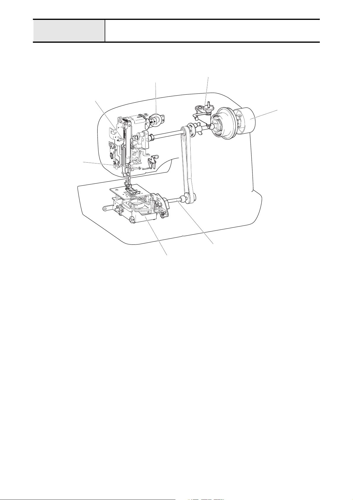
Outline of Mechanism Main Mechanisms
Sewing Machine
Thread guide mechanism
Needle bar /
Presser mechanism
Needle threader
mechanism
Bobbin winder mechanism
Upper shaft
mechanism
Feed / Rotary hook mechanism
Side feed mechanism
1 - 2
Page 11
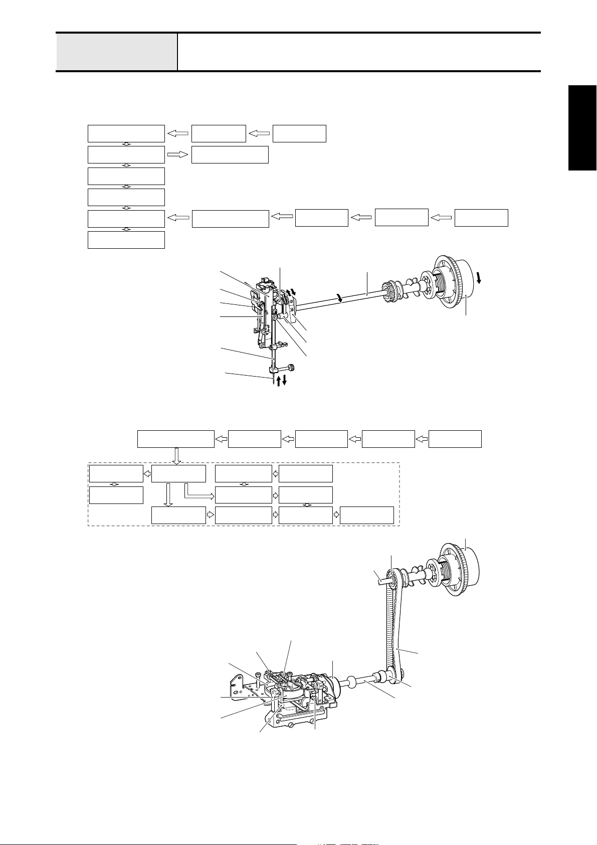
Outline of Mechanism Driveline
A) Up and down movement of needle bar, movement of thread take-up lever and zigzag
mechanism
Thread take-up
counter weight
Needle bar crank
Needle bar crank rod
Needle bar block
Needle bar
Needle
Needle bar supporter assy
Upper shaft
Thread take-up lever
Needle bar supporter
assy
Needle bar crank
Pulley
Z zigzag cam
Z pulse motor
Z zigzag lever
Needle bar
Needle
B) Movement of feed dog and rotary hook
Z zigzag lever
Z zigzag cam
Upper shaft
Thread take-up counter weight
Needle bar crank rod
Needle bar block
Z pulse motor
Pulley
Outline of
Mechanism
Lower shaft
gear
Outer rotary
hook
Timing pulley D Timing belt
Lower shaft
Vertical lever
Feed adjuster
Feed arm b
assy
Vertical
adjusting screw
Vertical adjusting screw
Feed bar
Feed arm A
Outer rotary hook
Lower shaft gear
Upper shaft
pulley
F pulse motor
Feed arm A
Feed bar Feed dog
Upper shaft
Feed dog
F pulse motor
Feed arm b assy
Upper shaft Pulley
Feed module
Pulley
Upper shaft pulley
Timing belt
Timing pulley D
Lower shaft
1 - 3
Page 12
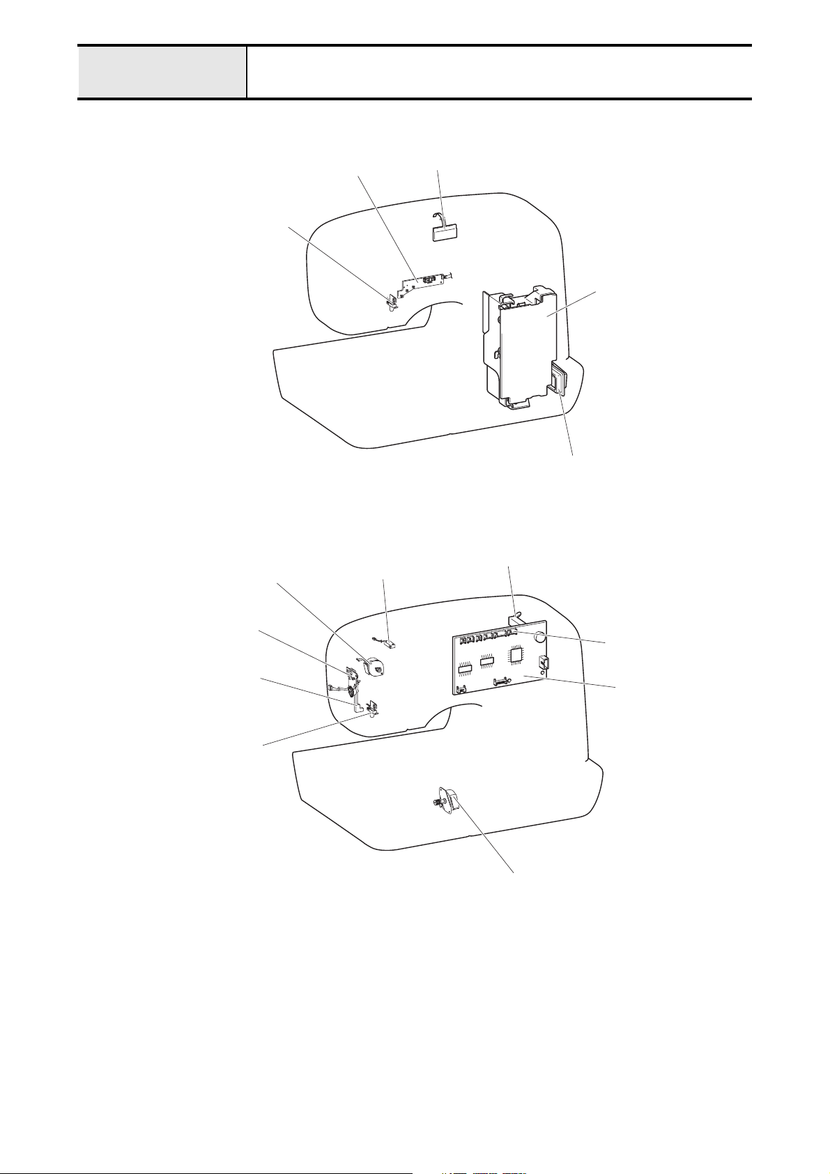
Outline of Mechanism Positions of electronic components
Sewing Machine
SS-VR PCB assy
LED Lamp SR assy
Z pulse motor
LCD PCB assy
Power PC assy
Power switch/Inlet assy
BWSW-S assy
PFSW-S assy
BH change switch assy
BH switch lever
LED Lamp SL assy
NP sensor
Main PCB assy
F pulse motor
1 - 4
Page 13
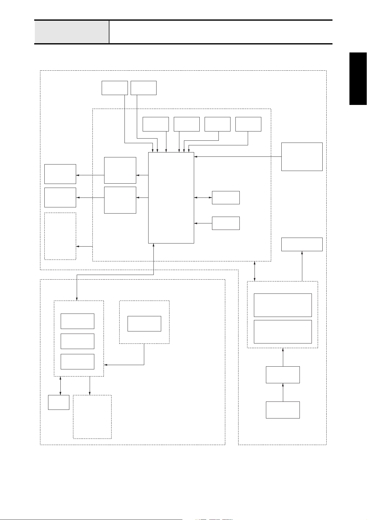
Outline of Mechanism Control system block diagram
CPS33 S34
ZPM
FPM
LED PCB
LIGHT
WHITE COLOR
LED (LEFT)
PFSW
MAIN PCB
ZPM
DRIVER
FPM
DRIVER
BHSW
BWSW
CPU
NP
SENSOR 2NPSENSOR 1SPSENSOR
EEPROM
RESET IC
FOOT
CONTROLLER
JACK
MAIN MOTOR
Outline of
Mechanism
FRONT
COVER
OPERATION PCB BK PCB
Z KEY X2
F KEY X2
PATTERN
SELECTION X4
LCD
LED PCB
LIGHT
WHITE COLOR
LED (RIGHT)
BK SW
POWER SUPPLY PCB
SWITCHING POWER
30V / 5V CIRCUIT
MAIN MOTOR
DRIVE CIRCUIT
POWER
SWITCH
INLET
1 - 5
Page 14
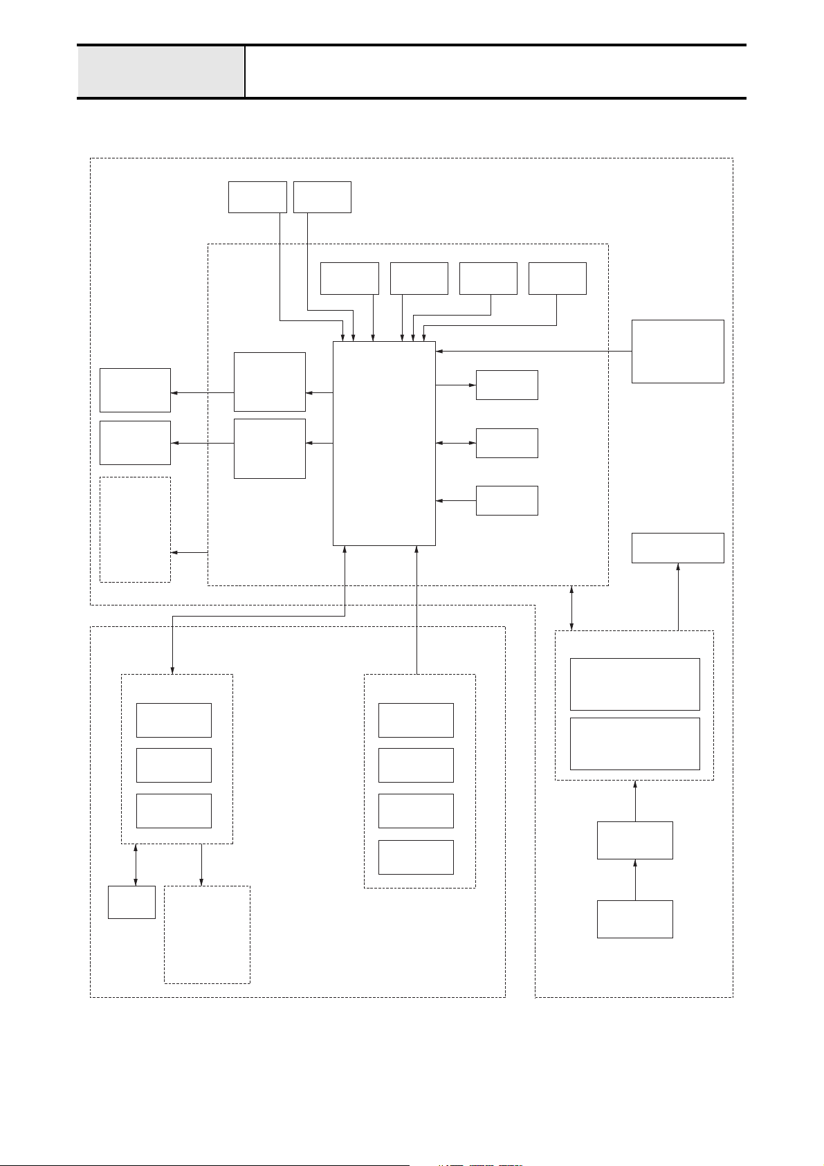
Outline of Mechanism Control system block diagram
CPS36 S37
ZPM
FPM
LED PCB
LIGHT
WHITE COLOR
LED (LEFT)
PFSW
MAIN PCB
ZPM
DRIVER
FPM
DRIVER
BHSW
BWSW
CPU
NP
SENSOR 2NPSENSOR 1SPSENSOR
FOOT
CONTROLLER
JACK
BUZZER
EEPROM
RESET IC
MAIN MOTOR
FRONT
COVER
OPERATION PCB
Z KEY X2
F KEY X2
PATTERN
SELECTION X4
LCD
LED PCB
LIGHT
WHITE COLOR
LED (RIGHT)
SSVR PCB
SS SW
BK SW
NP SW
SPEED VR
POWER SUPPLY PCB
SWITCHING POWER
30V / 5V CIRCUIT
MAIN MOTOR
DRIVE CIRCUIT
POWER
SWITCH
INLET
1 - 6
Page 15

Outline of Mechanism Operation of other electronic components
Start/Stop (SS) Switch . . . . . . . . . . . . . . . . . . . . . . Switch for starting and stopping the sewing machine. The machine
operates at a slow speed while the switch is being held down.
Reverse switch . . . . . . . . . . . . . . . . . . . . . . . This switch is for backtracking or ending a seam. If the switch is
pushed, it makes three to four stitches in that place and stops
automatically. If the switch is held down, it sews at a slow speed
in the reverse direction as long as the switch is held.
Raise needle switch . . . . . . . . . . . . . . . . . . . . This switch toggles the needle between the up and down positions.
Outline of
Mechanism
Operation PCB assembly
BH (buttonhole) switch . . . . . . . . . . . . . . . . This switch is for detecting the forward and rear ends of the
BH (button hole) lever switch . . . . . . . . . . . . . .
NP sensor . . . . . . . . . . . . . . . . . . . . . . . . . . . This sensor detects the drive timing for the pulse motor for
Speed sensor. . . . . . . . . . . . . . . . . . . . . . . . . This sensor detects the rotational speed of the main motor. It
Presser switch. . . . . . . . . . . . . . . . . . . . . . . . This switch detects the vertical position of the presser foot lifter.
BW (bobbin winder) switch . . . . . . . . . . . . . When the bobbin thread is wound, this switch detects whether
. . . . . . . . . . . . . . . . Input for pattern selection and other conditions necessary for sewing.
buttonhole according to the BH presser and lever.
This switch detects whether the BH lever is up or down.
zigzagging and feed, the vertical stop position for the needle. It
detects the upper shaft angle of rotation using a shutter attached
to the upper shaft and an optical sensor.
detects the upper shaft rotational speed using a shutter attached
to the upper shaft and an optical sensor.
the bobbin is set for winding or not.
Foot control jack. . . . . . . . . . . . . . . . . . . . . . . This is the jack for plugging in the foot controller when it is used.
LED lamp SR assy., SL assy. . . . . . . . . . . . . White LED lamps for illuminating the work space.
1 - 7
Page 16

1 - 8
Page 17

2
Disassembly
Main parts........................................ 2 - 2
Feed unit........................................ 2 - 19
Needle-presser unit ....................... 2 - 27
With the CD-ROM version, click to start the movie clip.
2 - 1
Page 18
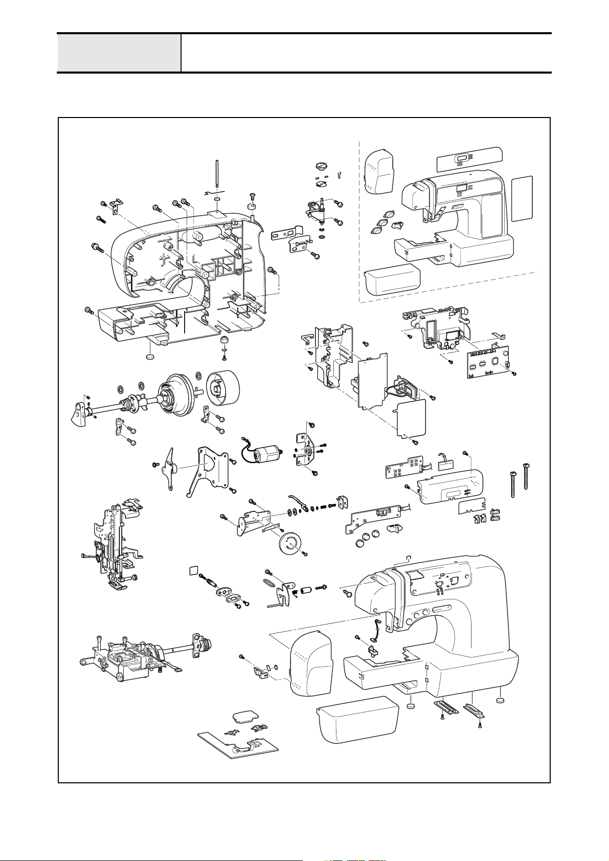
Main unit
Main parts location diagram
2 - 2
Page 19
Main unit
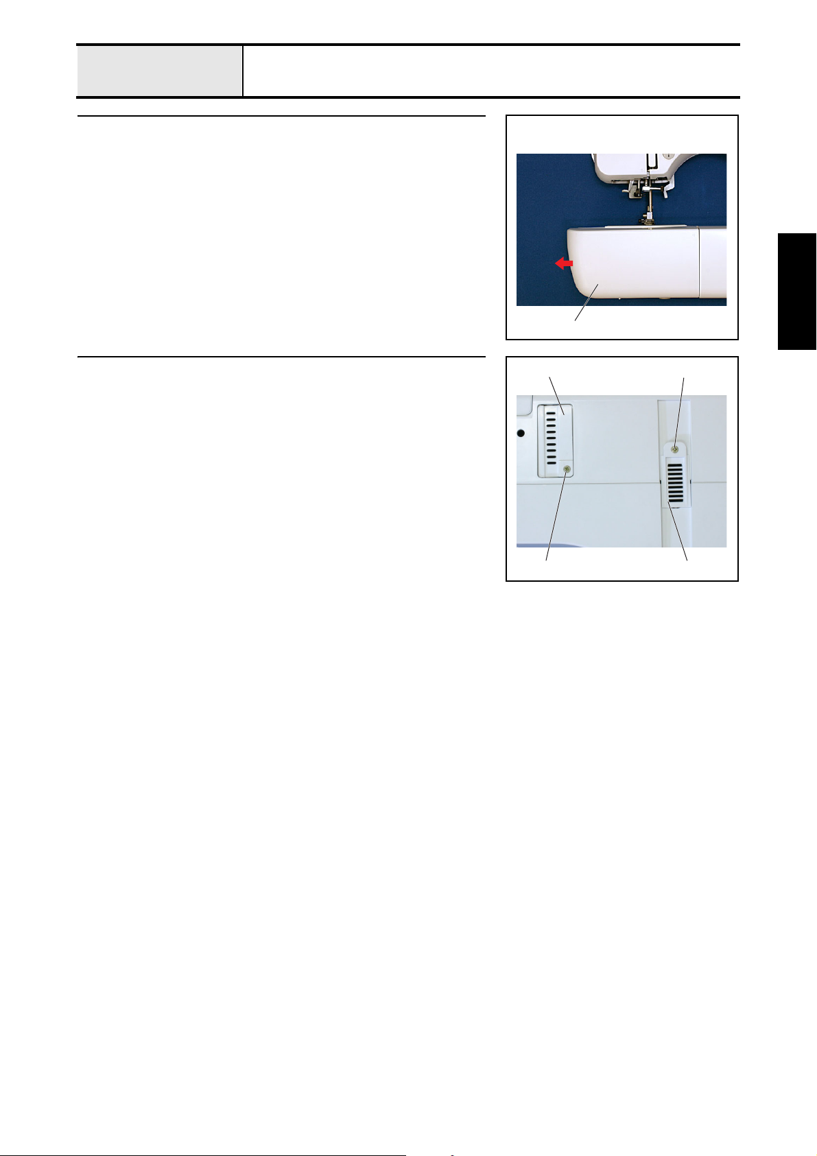
1 Accessory table removal
1. Remove the accessory table 1.
Main parts
1
Disassembly
2 Bottom cover removal
1. Remove the screw 1, and then remove the base cover 1.
2. Remove the screw 2, and then remove base cover A 2.
12
1 1
2 - 3
Page 20
Main unit
Main parts
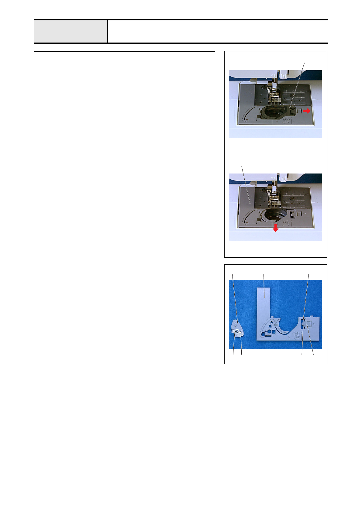
3 Needle plate B assembly removal
1. Remove the needle plate cover 1.
2. Remove the needle plate B assembly 2.
1
2
3-1 Needle plate B ASSY disassembly
1. Remove the cutter cover 2 from the needle plate B assembly 1.
2. Remove the spring plate 3 from the cutter cover 2, and then remove the
NT lower thread cutter 4.
3. Remove the 2 slide button hooks 5, and then remove the slide button 6.
21 5
6543
2 - 4
Page 21
Main unit
Main parts
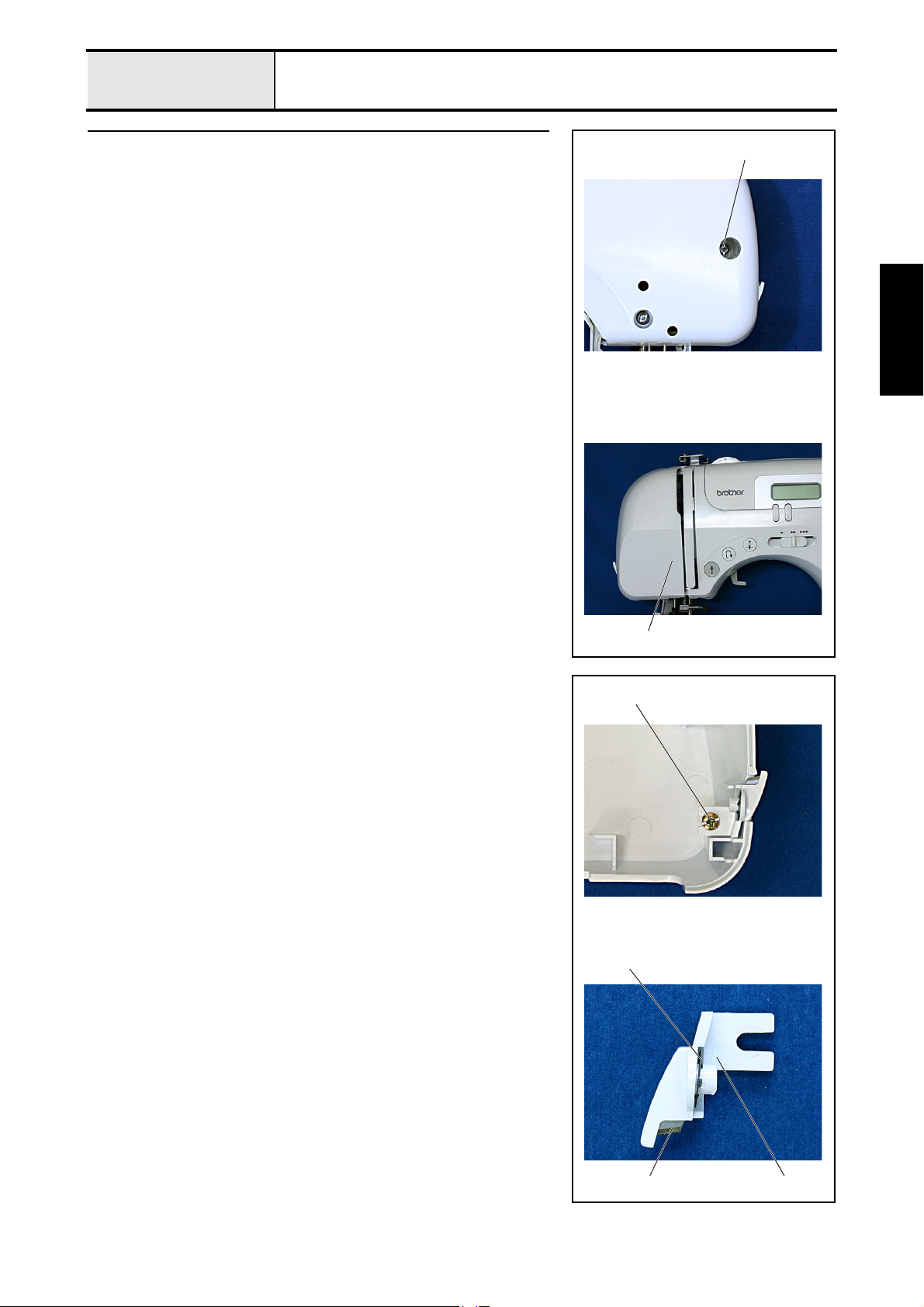
4 Face plate assembly removal
1. Remove the screw 1, and then remove the face plate assembly 1.
1
Disassembly
4-1 Face plate A ASSY disassembly
1. Remove the screw 1, and then remove the cutter cover assembly 1.
2. Remove the CS retaining ring 2, and then remove the NT lower thread
cutter 3.
1
1
2
31
2 - 5
Page 22
Main unit
Main parts
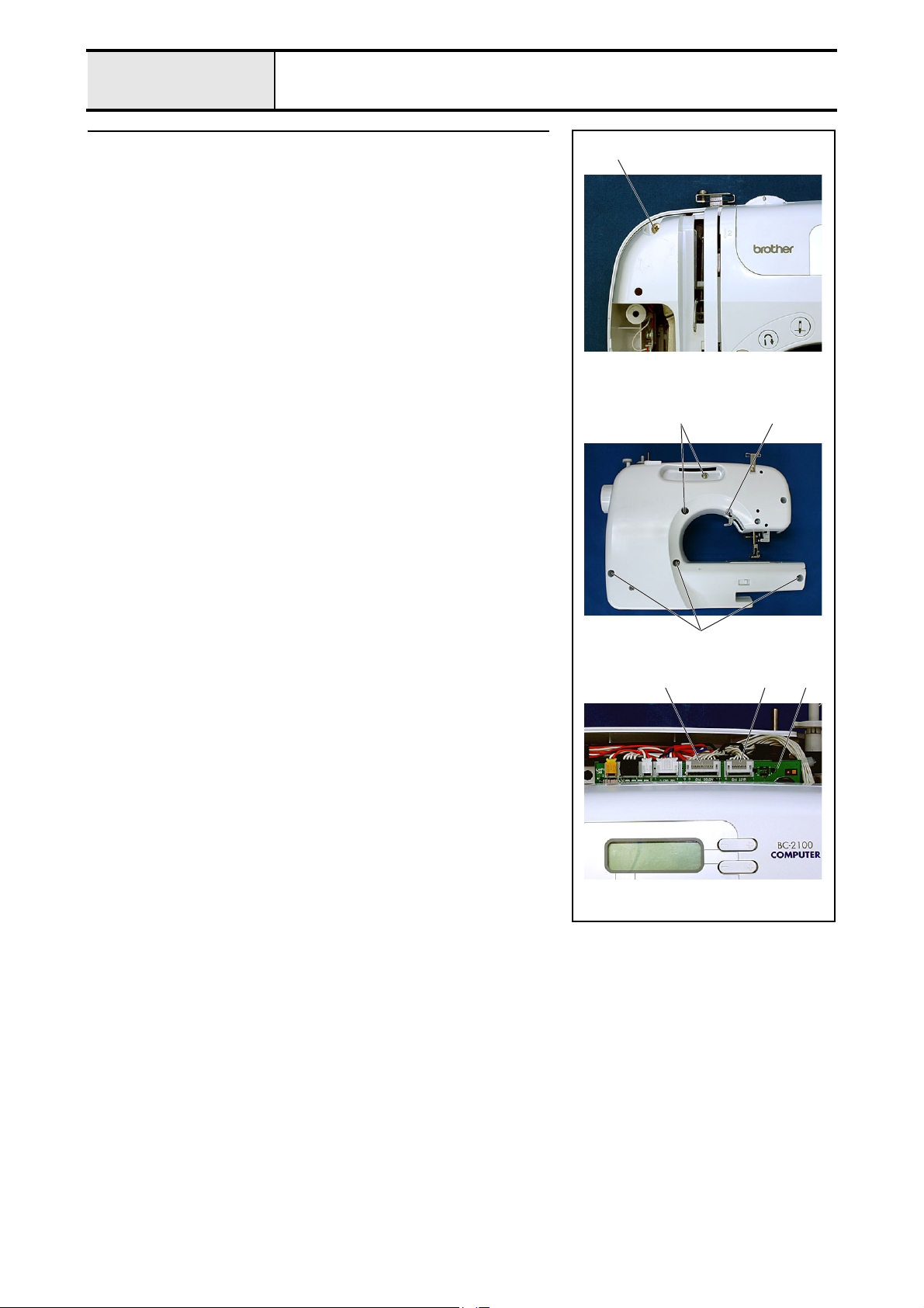
5 Front cover removal
1. Remove screws 1 (front, 1 pc.), 2 (rear, 1 pc.), and 3 (rear, 5 pcs.), and
then remove the front cover.
*Key point
• Disconnect the SSVR PCB lead wire connector 1 and the
operation PCB lead wire connector 2 from the main PCB
assembly 3 located near the front cover.
1
3
2
3
213
2 - 6
Page 23
Main unit
Main parts
6
Thread tension holder assembly and thread take-up holder B removal
1. Remove the two screws 1.
2. Remove the thread guide A assembly 1.
3. Remove the screw 2.
4. Remove the thread guide B assembly 2.
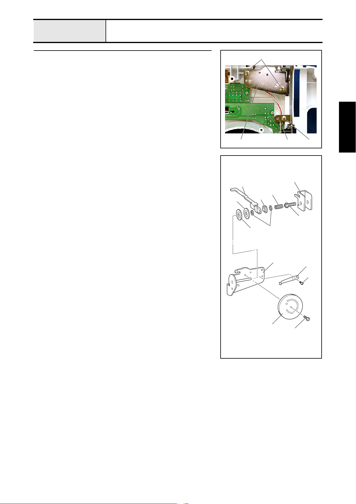
6-1 Thread tension holder ASSY disassembly
1. Remove the screw 1, and then remove the notch spring 2 from the thread
tension holder assembly 1.
2. Remove the thread dial shaft 3.
*Key point
• Turn the dial clockwise until it stops.
3. Remove the thread tension dial 4 and the thread tension plate assembly
5.
4. Remove the spring 6, washer 7, tension disc washer 8, thread release
plate 9, washer 7, tension disc B ;, and then tension disc A A in this
order from the caulking shaft of the thread tension holder assembly 1.
5. Remove the thread tension adjusting screw B from the thread tension plate
assembly 5.
0
9
A
1
221
Disassembly
5
6
8
B
7
4
1
2
1
3
2 - 7
Page 24
Main unit
Main parts
6-2 Thread take-up holder B disassembly
1. Remove the screw 1.
2. Remove the thread catching spring case 2 from thread take-up holder B
1.
3. Remove the thread take-up spring 3 from the thread catching spring case
2.
4. Remove the thread guide wire 4 from thread take-up holder B 1.
1
32
1
2
7 LED lamp removal
1. Disconnect the LED lamp connector 2 from the operation PCB 1.
2. Remove the screw 1, and then remove the LED lamp 3.
4
1
12
2 - 8
1 3
Page 25
Main unit
Main parts
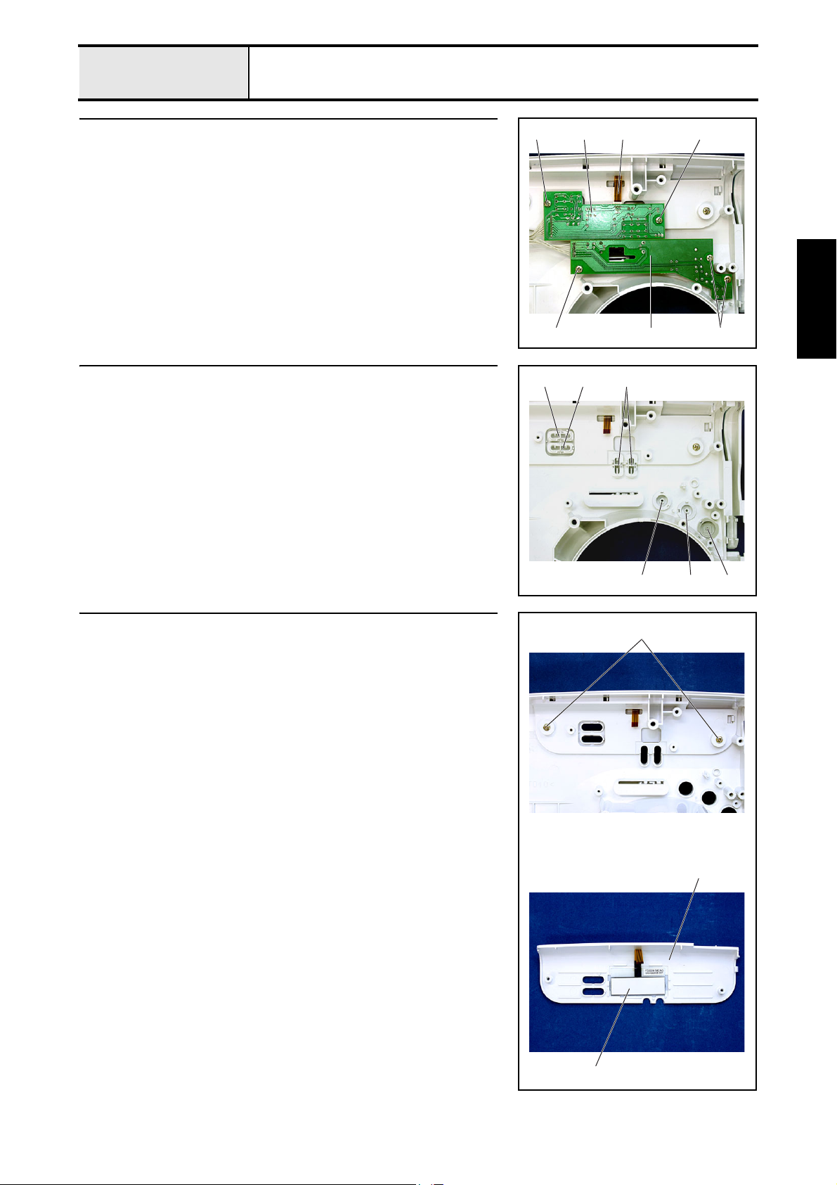
8
Operation PCB assembly and SSVR PCB assembly removal
1. Remove the 2 screws 1, and then remove the operation PCB assembly 1.
2. Disconnect the LCD cable 2 from the operation PCB assembly 1.
3. Remove the 3 screws 2, and then remove the SSVR PCB assembly 3.
*Key point
• Remove the bands (2 locations) securing the cords of the
operation PCB assembly 1 and the SSVR PCB assembly 3.
9 Button removal
1. Remove the 2 selecting buttons 1.
2. Remove manual button A 2 and manual button B 3.
3. Remove the SS button 4, the backstitching button 5, and the NP button
6.
1
12
23 1
3
1
22
Disassembly
10 Front panel and LCD removal
1. Remove the 2 screws 1.
2. Remove the front panel 1 and the LCD 2.
654
1
1
2
2 - 9
Page 26
Main unit
Main parts
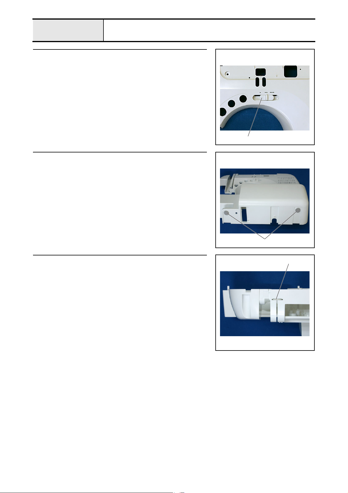
11 SV keytop removal
1. Remove the SV keytop 1.
*Key point
• Press the SV keytop hooks (2 locations) from the inside of the
front cover to remove the SV keytop.
12 Base plate rubber removal
1. Remove the 2 base plate rubbers 1.
1
13 Upper cover thread guide removal
1. Remove the upper cover thread guide 1.
1
1
2 - 10
Page 27
Main unit
Main parts
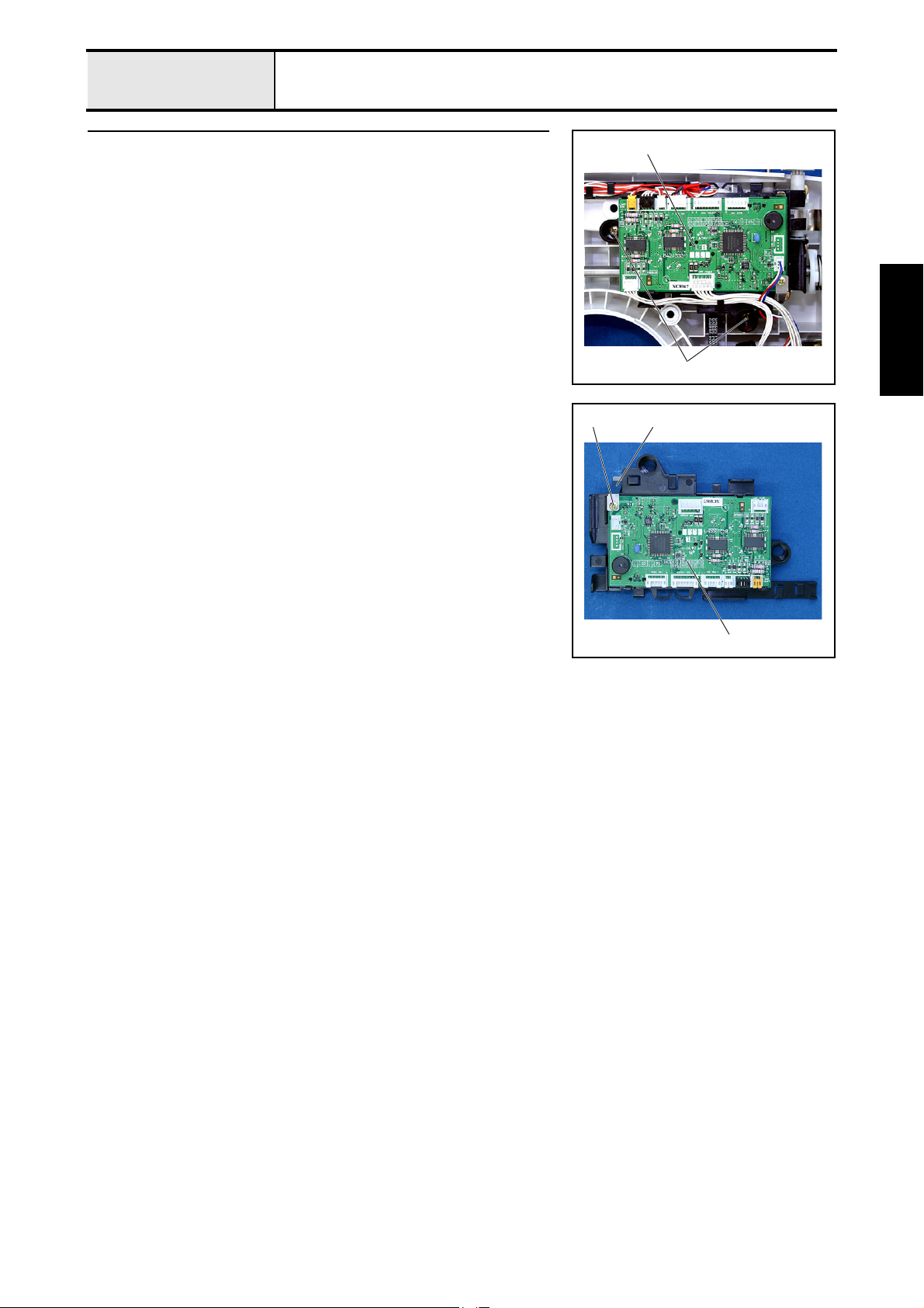
14 Main PCB assembly removal
1. Remove the 2 screws 1.
2. Remove the main PCB assembly 1.
14-1 Main PCB ASSY disassembly
1. Remove the screw 1.
2. Remove the main PCB plate spring 1, and then remove the main PCB 2.
1
1
1
Disassembly
1
2
2 - 11
Page 28
Main unit
Main parts
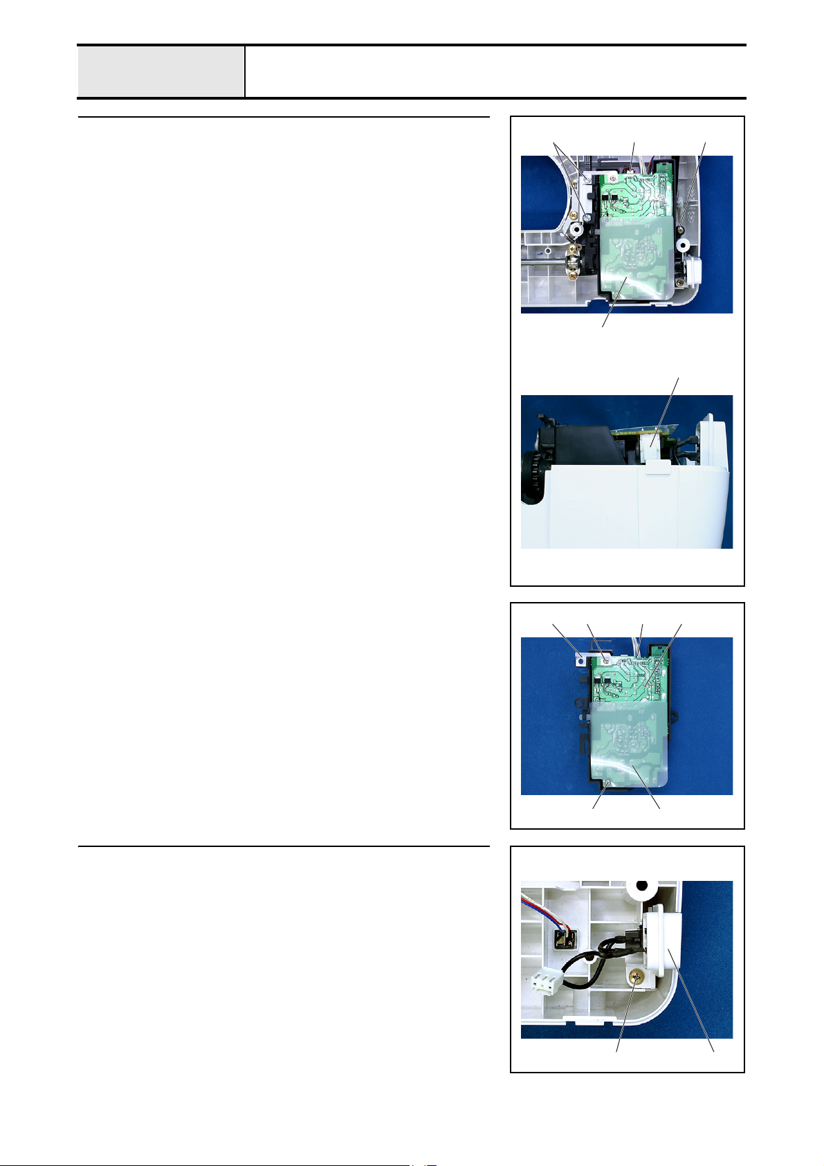
15 Power PCB assembly removal
1. Remove screws 1 and 2 (2 pcs. /1pc.), and then remove the power PCB
assembly 1.
2. Disconnect the main motor lead wire 2 and the inlet assembly connector
3.
*Key point
• Hold the hook on the inlet assembly connector 3 and pull it
out.
1 2 2
1
3
15-1 Power PCB ASSY disassembly
1. Disconnect the power lead wire assembly connector 1.
2. Remove the screw 1, and then remove the power plate spring 2.
3. Remove the screw 2, and then remove the insulator sheet 3.
4. Remove the power PCB 4.
16 Inlet assembly removal
1. Remove the screw 1, and then remove the inlet assembly 1.
121
2 3
4
2 - 12
1 1
Page 29
Main unit
Main parts
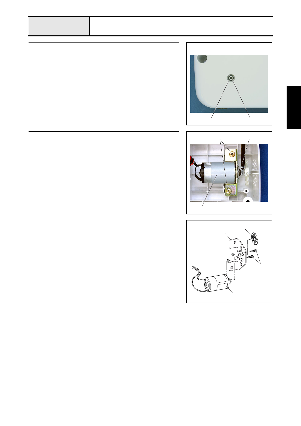
17 FC jack removal
1. Remove the jack nut 1, and then remove the FC jack assembly 2.
12
Disassembly
18 Main motor assembly removal
1. Remove the 2 screws 1, and then remove the main motor assembly 1.
2. Remove the motor belt 2 from the main motor assembly 1.
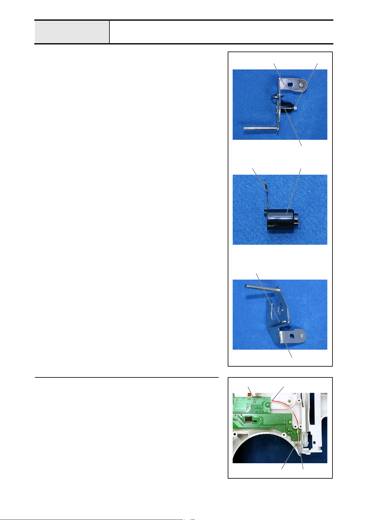
18-1 Main motor ASSY disassembly
1. Remove the motor fan 1.
2. Remove the 2 screws 1, and then remove the main motor 3 from the
motor holder 2.
1 2
1
1
2
1
3
2 - 13
Page 30
Main unit
Main parts
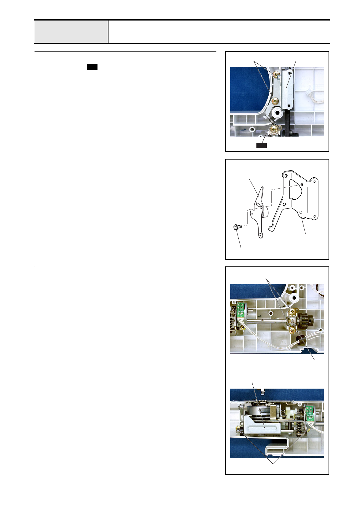
19 Tension pulley assembly removal
1. Remove spring .
2. Remove the 2 screws 1, and then remove the tension pulley assembly 1.
19-1 Tension pulley ASSY disassembly
1. Remove the screw 1, and then remove the tension pulley holder 2 from
the tension pulley assembly 1.
S09
1 1
S09
1
20 Feed unit assembly removal
1. Remove the 2 screws 1, and then remove the upper shaft bearing presser
1.
2. Remove the 2 screws 2, and then remove the feed unit assembly 2.
2
1
1
1
2
2 - 14
2
Page 31

Main unit
Main parts
21 Upper shaft assembly removal
1. Remove the screw 1.
2. Remove the 4 screws 2, and then remove the 2 upper shaft bearing
pressers 1.
3. Remove the upper shaft assembly 3 from the needle bar crank 2, and
then remove timing belt 420-5GT-6 4 and timing belt 372-2GT-6 5.
22 Needle-presser unit removal
1. Peel the label, and then remove the screw 1.
2. Remove the 2 screws 2, and then remove the needle-presser unit 1.
1 1 2 1
23 4 5
Disassembly
1
23 Plate spring removal
1. Remove the adjusting screw 1.
2. Remove the 2 screws 1, and then remove the adjusting plate 2 and the
plate spring 3.
1
2
1
213
2
3
1
2 - 15
Page 32

Main unit
Main parts
24 Bobbin base assembly removal
1. Remove the bobbin base assembly 2 from the bobbin winder shaft 1.
24-1 Bobbin base ASSY disassembly
1. Remove the bobbin thread cutter holder 2 from the bobbin base assembly
1, and then remove the NT lower thread cutter 3.
12
1
2
25 Bobbin winder assembly removal
1. Remove the screw 1, and then remove the bobbin winder shaft stopper 1
and the bobbin winder spring 2.
2. Remove the 2 screws 2, and then remove the bobbin winder assembly 3.
3. Remove the rubber ring 4 from the bobbin winder pulley.
3
1243
1
2
2 - 16
Page 33

Main unit
Main parts
26 Spool pin removal
1. Remove the spool pin spring 1 and pull out the spool pin 2.
2. Peel the spool pin stand 3.
2
1
Disassembly
3
27 Bobbin presser removal
1. Remove the screw 1, and then remove the bobbin presser 1.
28 Thread guide assembly removal
1. Remove the screw 1, and then remove the thread guide assembly 1.
11
1
1
2 - 17
Page 34

Main unit
Main parts
29 Base plate rubber removal
1. Remove the screw 1, and then remove the plain washer (M 3.5) 1 and
rubber cushion A 2.
2. Remove the base plate rubber 3.
3
1
12
2 - 18
Page 35

Main unit
Feed unit location diagram
Disassembly
2 - 19
Page 36

Main unit
Feed unit
1 Needle plate A assembly removal
1. Remove the 2 screws 1, and then remove the needle plate A assembly 1.
1-1 Needle plate A ASSY disassembly
1. Remove the screw 1, and then remove the F gear stopper plate 1.
2. Remove the screw 2, and then remove the stopper plate 2.
1 1
21
2 Spring removal
1. Remove the spring .
S10
3 Inner rotary hook bracket assembly removal
1. Remove the screw 1, and then remove the inner rotary hook bracket
assembly 1.
21
S10
2 - 20
11
Page 37

Main unit
Feed unit
4 Feed dog removal
1. Remove the 2 screws 1, and then remove the feed dog 1.
5 Vertical adjuster screw assembly removal
1. Remove spring .
2. Remove the M5 nut 1
3. Remove the vertical adjuster screw assembly 2.
S10
1
1
Disassembly
1
6 Outer rotary hook removal
1. Remove the screw 1, and then remove the outer rotary hook shaft 1,
washer 6 2, outer rotary hook assembly 3, spacer 4, and washer 6 2 .
7 Shaft supporter removal
1. Remove the 2 screws 1, and then remove the shaft supporter 1 and the
collar 2.
2
S04
2
1
3
4
1
2
11
1
2 - 21
Page 38

Main unit
Feed unit
8 Feed bar removal
1. Remove the retaining ring (CS4).
2. Remove the polyester slider 1, feed bar 2, and polyester slider 1 in this
order.
Start movie clip (CD-ROM version only)
9 Needle plate supporter shaft B removal
1. Remove nut 1 (M3) 1.
2. Remove needle plate supporter shaft B 2, and feed arm supporter 3.
*Key point
• Press the hook on the feed arm supporter 3 from the rear of
the feed bar to remove the supporter.
3. Remove the feed arm supporter 3 from the needle plate supporter shaft B
2.
2
1
Retaining ring CS4
2
1
2
3
3
2
2 - 22
3
Page 39

Main unit
Feed unit
10 Feed arm A assembly removal
1. Remove the screw 1, and then remove the set collar 1 and the thrust
wafer 2 in this order.
2. Remove the screw 2, and then remove the horizontal feed shaft 3.
3. Remove the feed arm A assembly 4 and the thrust wafer 2.
Start movie clip (CD-ROM version only)
10-1 Feed arm B ASSY disassembly
1. emove the retaining ring (CSTW-3.5), and then remove the feed arm B
assembly 1 and the polyester slider 2.
2. Remove the screw 1, and then remove the feed supporting plate 4 and
feed supporting plate B 5 from the feed arm B 3.
1
3
2
1
2
Retaining ring CSTW-3.5
4
2
Disassembly
1
2
3
4
15
2 - 23
Page 40

Main unit
Feed unit
11 Feed adjuster assembly removal
1. Remove the feed adjuster assembly 1, polyester slider 2, and spring
in this order.
Start movie clip (CD-ROM version only)
11-1 Feed adjuster disassembly
1. Remove spring , and then remove the F gear 2 from the feed adjuster
1.
S05
S06
S06
S05
1
2
12 Vertical lever removal
1. Remove the 4 retaining rings (E3).
2. Pull out the vertical feed shaft 1, and then remove the plain washer (L4)
2, spring , vertical lever 3, and drop knob 4.
Start movie clip (CD-ROM version only)
S07
12
S05
4
2
3
S07
Retaining ring E3
Retaining ring E3
1
Retaining ring E3
2 - 24
Page 41

Main unit
Feed unit
13 FPM holder assembly removal
1. Remove the screw 1, and then remove spring .
2. Remove the screw 2, and then remove the FPM holder assembly 1.
13-1 FPM disassembly
1. Remove the lead wire assembly (FPM-LE) 1.
2. Remove the 2 screws 1, and the remove the FPM 2.
3. Remove the rubber 3.
S08
211
S08
Disassembly
2
14 Timing pulley D removal
1. Remove the 2 screws 1, and then remove timing pulley D 1.
2. Remove the retaining ring (E6), and then pull out the lower shaft bushing
2.
1
Retaining ring E6
1
3
1
12
2 - 25
Page 42

Main unit
Feed unit
15 Lower shaft assembly removal
1. Remove the retaining ring (E6), and then remove the thrust washer 1.
2. Remove the lower shaft assembly 2.
*Key point
• Push down the lower shaft assembly 2 to remove it.
• Check that the gear does not contact the base plate.
3. Remove the 2 screws 1, and then remove the thrust wafer 1 and the set
collar 3.
1
Retaining ring E6
2
3
1
2
16 Lower shaft bushing removal
1. Remove the 3 screws 1.
2. Remove bushing presser B 1 and the lower shaft bushing 2.
2
1
1
1
2 - 26
Page 43

Main unit
Needle-presser unit location diagram
Disassembly
2 - 27
Page 44

Main unit
Needle-presser unit
1 Threader hook assembly
1. Pull the needle thread slider 1 toward you, and then remove the threader
hook assembly 2.
2 LED lamp left assembly removal
1. Remove the screw 1, and then remove the LED lamp left assembly 1.
1
2
1
3 BH switch assembly removal
1. Remove the screw 1, and then remove the BH switch assembly 1.
4 Thread take-up lever and needle bar crank removal
1. Remove the needle bar crank rod 1.
2. Remove the screw 1, and then remove the needle bar crank 3 from the
thread take-up lever 2.
1
1
1
1
2
3
2 - 28
1
Page 45

Main unit
Needle-presser unit
5 Thread take-up lever link removal
1. Remove the retaining ring (E5) and spring washer 1, and then remove the
thread take-up lever link 3 from the shaft 2.
2. Remove the screw 1, and then pull the shaft 2 out of the base holder.
Start movie clip (CD-ROM version only)
6 Needle bar assembly removal
1. Loosen the screws 1 and 2, and then pull the needle bar 1 down and
remove the needle thread block 2 and the needle bar block 3.
Start movie clip (CD-ROM version only)
1 2
Retaining ring E5
3
1232
1
Disassembly
6-1 Needle bar ASSY disassembly
1. Remove the screw 1, and then remove the needle block assy 1.
1
11
2 - 29
Page 46

Main unit
Needle-presser unit
7 Needle holder assembly removal
1. Remove springs and .
2. Remove the screw 1, and then remove the shaft 1, needle holder block
2, and needle holder assembly 3.
*Key point
• Pull out the needle holder assembly from the top.
Start movie clip (CD-ROM version only)
S02 S03
S02
2
1
1
S03
3
2 - 30
Page 47

Main unit
Needle-presser unit
7-1 Needle holder ASSY disassembly
1. Remove spring .
2. Remove the screw 1, and then remove the plate 1.
3. Remove the screw 2. Pull out the shaft 2, and then remove needle holder
shaft A 3.
4. Remove the screw 3, and then remove the zigzag adjusting nut 4.
Start movie clip (CD-ROM version only)
S01
1
3
2
S01
1
2
Disassembly
34
2 - 31
Page 48

Main unit
Needle-presser unit
8 Presser bar removal
1. Remove the screw 1. Pull out the presser bar 1, and then remove the
spring 2 and the presser bar clamp 3.
*Key point
• Remove the presser bar 1 and the presser feed holder
assembly 4.
2. Remove the J foot 5 from the presser feed holder assembly 4.
3. Remove the screw 2, and then remove the presser feed holder assembly
4.
Start movie clip (CD-ROM version only)
1
23
9 Z zigzag lever assembly removal
1. Remove the retaining ring (E4), and then remove the Z zigzag lever 1.
2. Remove the polyester slider 2.
Start movie clip (CD-ROM version only)
2154
Retaining ring E4
1
2 - 32
2
Page 49

Main unit
Needle-presser unit
9-1 Z zigzag lever disassembly
1. Pull out the Z zigzag cap 2 from the Z zigzag lever 1.
10 Z zigzag camp removal
1. Remove the retaining ring (E3), and then remove the Z zigzag cam 1.
2. Remove the rubber 2.
Start movie clip (CD-ROM version only)
1
Retaining ring E3
1
2
Disassembly
11 Shaft bushing removal
1. Remove the 2 screws 1, and then remove the shaft bushing 1.
12 Presser foot lifter removal
1. Remove the retaining ring (E4), and then remove the presser foot lifter 1.
2
1
1
Retaining ring E4
1
2 - 33
Page 50

Main unit
Needle-presser unit
13 Thread release lever removal
1. Remove the retaining ring (CS4), and then remove the thread release lever
1 and the spring 2.
14 Lock nut removal
1. Remove the lock nut 1, and then remove the screw 1.
2
Retaining ring CS4
11
1
15 Z pulse motor removal
1. Remove the 2 screws 1, and then remove the Z pulse motor 1.
16 Presser switch assembly removal
1. Remove the screw 1, and then remove the presser switch 1.
1
1
1
2 - 34
1
Page 51

3
Assembly
Main parts........................................ 3 - 2
Feed unit........................................ 3 - 22
Needle-presser unit ....................... 3 - 34
With the CD-ROM version, click to start the movie clip.
3 - 1
Page 52

Main unit
Main parts location diagram
3 - 2
Page 53

Main unit
Main parts
1 Base plate rubber attachment
1. Attach the base plate rubber 1 to the arm bed cover.
• Attach rubber cushion A 2 and the plain washer (M3.5) 3 to the
arm bed cover with the screw 1.
1
Taptite, Pan B
M3X12
Color; Silver
2 Thread guide assembly attachment
1. Attach the thread guide assembly 1 to the arm bed cover.
2. Temporarily tighten the screw 1.
*Key point
• Tighten the screw after performing "4 - 16 Bobbin winder
(uneven bobbin winding and bobbin winding amounts)
adjustment"
Torque
0.59 – 0.78 N
·m
1
1
32
1
Assembly
1
3 Bobbin presser attachment
1. Attach the bobbin presser 1 with the screw 1.
*Key point
• Place the bobbin presser with the smaller end facing the rear.
• Tighten the screw after performing "4 - 16 Bobbin winder
(uneven bobbin winding and bobbin winding amounts)
adjustment"
1
Giza Tite
4X12
Color; Gold
Taptite, Pan B (S/P washer)
M3X12
Color; Silver
Torque
0.88 – 1.18 N
Torque
0.39 – 0.78 N
·m
·m
1
11
3 - 3
Page 54

Main unit
Main parts
4 Spool pin attachment
1. Attach the spool pin stand 1 so that it does not protrude from the
attachment section.
2. Insert the spool pin 2 into the arm bed cover. Insert the pin from the
grooved end.
3. Attach the spool pin spring 3 to the arm bed cover.
*Key point
• Check that the spool pin 2 moves lightly.
1
2
3
3 - 4
Page 55

Main unit
Main parts
5 Bobbin winder assembly attachment
1. Attach the rubber ring 1 to the bobbin winder pulley.
2. Insert the bobbin winder shaft 2 into the groove on the arm bed cover, and
secure the shaft with the 2 screws 1.
3. Insert the BW switch lever 3 into the bobbin winder shaft stopper 4.
4. Set the bobbin winder spring 5 and then the bobbin winder shaft stopper
4 to the stopper attachment section of the arm bed cover, and secure them
with the screw 2.
*Key point
• Check that the bobbin winder spindle base passes over the
bobbin winder spring when the bobbin winder is switched.
• Check that the bobbin winder spring returns to the original
position when the bobbin winder is switched.
1
14
Assembly
1
2
Giza Tite
5X16
Color; Gold
Torque
1.18 – 1.57 N
·m
2
54 6
2
3 - 5
Page 56

Main unit
Main parts
6 Bobbin base assembly attachment
1. Attach the bobbin base assembly 1.
6-1 Bobbin base ASSY assembly
1. Attach the 2 NT lower thread cutters 2 and the bobbin thread cutter holder
3 to the bobbin base assembly 1.
1
1
3
7 Plate spring attachment
1. Attach the adjusting plate 1 and then the plate spring 2 from the inside of
the arm bed cover with the 2 screws 1.
2. Tighten the adjusting screw 3 to the plate spring 2.
1
Taptite, Bind B
M4X10
Color; Gold
Torque
0.78 – 1.18 N
·m
3
2
231
1
2
1
3 - 6
Page 57

Main unit
Main parts
8 Needle-presser unit attachment
1. Attach the needle-presser unit 1 to the arm bed cover with screws 1 and
2 (1 pc. and 2 pcs. respectively).
*Key point
• Lift the presser foot lifter 2 and insert it into the hole on the
arm bed cover 3 to set the needle-presser unit 1 to the
attachment position.
Start movie clip (CD-ROM version only)
1
Screw, Pan
M3X25
Color; Silver
Torque
0.78 – 1.18 N
1
2
Assembly
·m
2
Giza Tite
5X20
Color; Gold
Torque
1.18 – 1.57 N
·m
1
2
3 - 7
Page 58

Main unit
Main parts
9 Upper shaft assembly attachment
1. Pass timing belt 420-5GT-6 (timing belt) 2 and timing belt 372-2GT-6
(motor belt) 3 to the upper shaft assembly 1.
2. Attach the needle bar crank 5 to the thread take-up lever crank 4.
3. Set the upper shaft bushing 6 to the arm bed cover attachment position.
4. Attach the 2 upper shaft bearing pressers 78 with the 4 screws 1.
*Key point
• Check that the bobbin base assembly is on the left side.
• Attach the left upper shaft bearing presser 7 so that the
projecting part of 7 is positioned at the upper right. And attach
the right upper shaft bearing presser 8 so that the projecting
part of 8 is positioned at the lower shaft.
5. Apply 1 or 2 drops of OILER to the matching section of the upper shaft
and the upper shaft bushing.
6. Align the D-cut face of the needle bar crank with the screw hole on the
thread take-up lever crank, and tighten the screw 2.
Apply OILER to the matching section of the upper shaft
and the upper shaft bushing.
1 - 2 drops
XZ0206***
1
23
54
1
Giza Tite
5X16
Color; Gold
Torque
1.18 – 1.57 N
·m
6
7 1 8
66
D cut face
D cut face
2
2
3 - 8
2
Set Screw, Socket (FT)
M5X5
Color; Black
Torque
1.18 – 1.57 N
·m
Page 59

Main unit
Main parts
10 Feed unit assembly attachment
1. Fit the feed unit 1 to the arm bed cover attachment position, and secure
them with the 2 screws 1.
2. Fit the lower shaft bushing 2 to the arm bed cover attachment position, set
the lower shaft bearing presser 3, and secure them with the 2 screws 2.
*Key point
• Set the lower shaft bearing presser 3 so that the projecting
part of 3 is positioned at upper right.
3. Apply 1 or 2 drops of OILER to the matching section of the lower shaft 4
and the lower shaft bushing 2.
Apply OILER to the matching section of the lower shaft
and the lower shaft bushing.
1
Giza Tite
5X16
Color; Gold
1 - 2 drops
XZ0206***
Torque
1.18 – 1.57 N
1
1
2
Assembly
·m
2
Giza Tite
5X16
Color; Gold
Torque
1.18 – 1.57 N
11 Upper shaft and lower shat phase matching
1. Rotate the upper shaft 1 until the trench on the upper shaft pulley 2 is at
the front.
2. Turn the lower shaft 3 to the point where the mark on the outer rotary
hook 4 is at the front, the larger feed cam 5 is at the rear, and the hole on
the lower shaft 6 is at the top.
3. Pull the timing belt 7 and hang it over the timing pulley D 8.
Start movie clip (CD-ROM version only)
·m
8
1
4
2
24
7
3
3
7
6
5
3
3 - 9
Page 60

Main unit
Main parts
12 Tension pulley assembly attachment
1. Attach the tension pulley assembly 1 to the arm bed cover with the 2
screws 1.
2. Attach spring .
*Key point
• Perform "4 - 3 Timing belt tension adjustment.
1
S09
12-1 Tension pulley ASSY assembly
1. Align the boss 3 on the tension pulley holder 2 with the hole on the
tension pulley assembly 1, and secure the tension pulley assembly with
the screw 1.
S09
19.8
Giza Tite
5X16
Color; Gold
5
Torque
1.18 – 1.57 N
SPRING
XC2538***
1 1
·m
S09
2
1
1
Screw, Pan (S/P washer)
M4X8DA
Color; Silver
Torque
1.18 – 1.57 N
13 Main motor assembly attachment
1. Hang the motor belt 2 over the main motor assembly 1.
2. Attach the main motor assembly 1 to the arm bed cover assembly with the
2 screws 1.
*Key point
• Perform "4 - 4 Motor belt tension adjustment.
1
Giza Tite
5X16
Color; Gold
13-1 Main motor assembly
1. Attach the main motor 2 to the motor holder 1 with the 2 screws 1.
2. Attach the motor fan 3.
Torque
0.29 – 0.49 N
·m
·m
3
1
1 2
1
3
1
3 - 10
1
Screw, Pan (S/P washer)
M3X8DB
Color; Silver
Torque
0.59 – 0.78 N
·m
1
2
Page 61

Main unit
Main parts
14 FC jack attachment
1. Insert the FC jack assembly 1 from the inside of the arm bed cover
assembly.
2. Attach the jack nut 2 from the outside of the arm bed cover assembly.
*Key point
• Pass the lead wire of the FC jack assembly 1 through the
rear of the main motor.
15 Inlet assembly attachment
1. Attach the inlet assembly 1 with the screw 1.
21
Assembly
1
Taptite, Bind B
M4X10
Color; Gold
Torque
0.78 – 1.18 N
·m
1 1
3 - 11
Page 62

Main unit
Main parts
16 Power PCB assembly attachment
1. Attach the power unit assembly 1 with screws 1 and 2 (1 pc. and 2 pcs.
respectively).
*Key point
• Attach the power plate spring 3 to the upper screw 2.
2. Attach the main motor lead wire assembly connector 4 to the power PCB
2.
3. Attach the inlet assembly connector 5 to the power PCB 2.
1
Taptite, Bind B
M4X10
Color; Gold
Torque
0.78 – 1.18 N
21243
1
52
·m
2
Screw, Bind
M4X8
Color; Silver
Torque
1.18 – 1.57 N
16-1 Power PCB ASSY assembly
1. Attach the power PCB 2 and the insulator sheet 3 to the insulation cover
1 with the screw 1.
2. Attach the power plate spring 1 with the screw 2.
1
2
Taptite, Bind B
M3X8
Color; Gold
Torque
0.39 – 0.78 N
·m
·m
1
24
1 3
2
3 - 12
Page 63

Main unit
Main parts
17 Main PCB assembly attachment
1. Insert the bobbin winder switch of the main PCB 2 into the slot on the
bobbin winder stopper plate 1, and then insert the boss on the arm bed
cover into the screw hole on the shutter cover 3.
2. Main PCB assembly 4 with the 2 screw 1.
*Key point
• Refer to "5 - 1 Special Instructions of Wiring" for wiring details.
1
3
2
4
Assembly
1
Taptite, Bind B
M4X10
Color; Gold
Torque
0.78 – 1.18 N
17-1 Main PCB assembly
1. Attach the main PCB plate spring 2 and the main PCB 3 to the shutter
cover 1 with the screw 1.
1
Taptite, Bind B
M3X8
Color; Gold
Torque
0.39 – 0.78 N
18 Upper cover thread guide attachment
1. Attach the upper cover thread guide 1.
·m
·m
1
12
1 3
1
3 - 13
Page 64

Main unit
Main parts
19 Base plate rubber attachment
1. Attach the 2 base rubber plates 1.
20 SV keytop attachment
1. Attach the SV keytop 1.
1
21 Front panel LCD attachment
1. Attach the LCD 1 and the front panel 2 with the 2 screws 1.
*Key point
• Insert the LCD cable 3 into the hole in the upper section of
the front cover.
1
2
1
1
3 - 14
1
Taptite, Bind B
M3X8
Color; Gold
Torque
0.39 – 0.78 N
·m
3
Page 65

Main unit
Main parts
22 Button attachment
1. Attach the SS button 1, the backstitching button 2, and the NP button 3.
2. Attach manual button A 4, manual button B 5, and 2 selecting buttons
6.
123
456
45 6
Assembly
23
Operation PCB assembly and SSVR PCB assembly attachment
1. Attach the operation PCB assembly 1 with the 2 screws 1.
2. Attach the SSVR PCB assembly 2 with the 3 screws 2.
*Key point
• Insert the speed dial of the SSVR PCB assembly 3 into the
slot on the SV keytop 4.
3. Connect the LCD cable 5 to the operation PCB assembly 1.
*Key point
• Bind the operation PCB cord and SSVR PCB cord, and secure
these with two bands. <Refer to "5 - 1 Special Instructions of
Wiring" for wiring details.>
1
321
15
2
3
1
22
1
1
2
Taptite, Bind B
M3X8
Color; Gold
Torque
0.39 – 0.78 N
·m
4
2
3 - 15
Page 66

Main unit
Main parts
24 LED lamp attachment
1. Attach the LED lamp 1 with the screw 1.
2. Attach the LED lamp connector 2 to the operation PCB 3.
*Key point
• Secure the LED lamp lead wire 1 to the rib on the front cover.
• <Refer to "5 - 1 Special Instructions of Wiring" for wiring
details.>
1
25
Thread tension holder assembly and thread take-up holder B attachment
1. Attach the thread tension holder assembly 1 with the 2 screws 1.
2. Attach the thread take-up holder B 2 with the screw 2.
*Key point
• Insert the wire of the thread tension holder assembly B 2 into
the groove on the front cover, and then insert the boss into the
hole on the front cover.
Taptite, Bind B
M3X8
Color; Gold
Torque
0.39 – 0.78 N
·m
32
1 1
1
1
2
Taptite, Bind B
M4X14
Color; Gold
Torque
0.78 – 1.18 N
25-1 Thread tension holder ASSY assembly
1. Attach tension disc A 2, tension disc B 3, washer 4, thread release plate
5, tension disc washer 6, washer 7, and spring 8 in this order to the
caulking shaft of the thread tension holder assembly 1.
2. Attach the thread tension adjusting screw ; to the thread tension plate 9.
3. Engage the ridge of the thread tension plate 9 with the groove on the
thread tension dial A, insert them into the caulking shaft of the thread
tension holder assembly 1, and secure them with the tension dial shaft B.
4. Attach the notch spring C to the thread tension holder assembly 1 with
the screw 1.
*Key point
• Hold the notch spring with the ridge side up, and insert it into
the lower thread tension dial A. Align the round hole with the
boss on thread tension holder assembly 1.
·m
3
5
2
6
4
8
1
7
221
9
;
C
1
3 - 16
1
Screw, Pan
M3X4
Color; Silver
Torque
0.78 – 1.18 N
·m
A
B
Page 67

Main unit
Main parts
25-2 Thread take-up holder B assembly
1. Attach the wire 2 to thread take-up holder B assembly 1.
2. Insert the tip of the thread take-up spring 3 into the second hole from the
bottom on the thread catching spring case 4, secure 9.7 to 10.7 mm from
the top of the groove on thread take-up holder B assembly 1 to the ridge
of the thread hanging section on the thread take-up spring, and attach the
thread take-up spring to thread take-up holder B assembly 1 with the
screw 1.
*Key point
• Attach the thread hanging section on the thread take-up spring
to the section between the ribs of the thread catching spring
case.
• Insert the 2 ribs of the thread catching spring case into the slot
on thread take-up holder B 1.
2
1
34
Assembly
1
Screw, Pan (S/P washer)
M3X18DA
Color; Silver
Torque
0.59 – 0.78 N
·m
1
9.7-10.7mm
2
4
3
1
4
3 - 17
Page 68

Main unit
Main parts
26 Front cover attachment
1. Connect the SSVR PCB connector 1 and the operation PCB connector 2
to the main PCB 3.
*Key point
• Pass the lead wires to the hook section of the shutter cover 4
while preventing them from lifting or disconnecting.
<Refer to "5 - 1 Special Instructions of Wiring" for wiring
details.>
2. Attach the front cover to the arm bed cover with screws 1 (front, 1 pc.), 2
(rear, 1 pc.), and 3 (rear, 5 pcs.).
213
1
1
2
3
Giza Tite
4X12
Color; Gold
Giza Tite
4X25
Color; Gold
Giza Tite
5X16
Color; Gold
Torque
0.88 – 1.18 N
Torque
0.88 – 1.18 N
Torque
1.18 – 1.57 N
·m
·m
·m
3
2
3
3 - 18
Page 69

Main unit
Main parts
27 Face plate A assembly attachment
1. Attach the face plate A assembly 1 with the screw 1.
1
1
Assembly
1
Taptite, Cup P
M4X20
Color; Silver
Torque
0.78 – 1.18 N
27-1 Face plate A ASSY assembly
1. Attach the NT lower thread cutter 2 to the cutter cover 1, and then attach
the CS retaining ring 3.
*Key point
• Insert the narrow edge of the NT lower thread cutter 2 into
the cutter cover 1 first.
• Align the tab of the CS retaining ring with the groove on the
shaft of the cutter cover 1.
2. Attach the cutter cover assembly to face plate A 4 with the screw 1.
·m
3
21
1
1
Taptite, Bind B
M3X8
Color; Gold
Torque
0.39 – 0.78 N
·m
3 - 19
Page 70

Main unit
Main parts
28 Needle plate B assembly attachment
1. Attach the needle plate B assembly 1.
2. Attach the needle plate cover 2 to the needle plate B assembly 1.
1
2
28-1 Needle plate B ASSY assembly
1. Attach the slide button 1 to needle plate B 2.
2. Attach the NT lower thread cutter 3 and the spring plate 4 to the cutter
cover 5.
3. Attach the cutter cover to needle plate B 2.
29 Base cover attachment
1. Attach the base cover 1 with the screw 1.
2. Attach base cover A 2 with the screw 2.
52
134
12
3 - 20
1
Screw, Flat B
M3X8
Color; Gold
Torque
0.39 – 0.78 N
·m
2 1
Page 71

Main unit
Main parts
30 Accessory table attachment
1. Attach the accessory table 1.
1
Assembly
3 - 21
Page 72

Main unit
Feed unit location diagram
3 - 22
Page 73

Main unit
Feed unit
1 Lower shaft bushing attachment
1. Attach the lower shaft bushing 2 and bushing presser B 3 to the base
plate assembly 1 with the 3 screws 1.
1
Taptite, Bind B
M3X6
Color; Gold
Torque
0.39 – 0.78 N
2 Lower shaft assembly attachment
1. Temporarily tighten the 2 screws 1 to the set collar 1, and attach the set
collar to the lower shaft assembly 2.
*Key point
• Set the set collar with the machined surface facing out.
2. Insert the thrust washer 3 into the lower shaft assembly 2, and attach
them to the lower shaft bushing 4.
3. Insert the thrust washer 5 into the lower shaft assembly 2, and attach the
retaining ring (E6).
4. Push the lower shaft assembly 2 from the retaining ring side, move the set
collar 1 to the lower shaft bushing 4, and then secure them with the 2
screws 1.
Start movie clip (CD-ROM version only)
·m
3
2
1
2
1
1
31
Assembly
1
Set Screw, Socket (CP)
M4X4
Color; Black
Torque
0.78 – 1.18 N
·m
3 Timing pulley D attachment
1. Insert the upper shaft bushing 2 into the lower shaft assembly 1, and
attach the retaining ring (E6).
Insert the timing pulley D 3 into the lower shaft assembly 1, and secure
them with the 2 screws 1.
1
Set Screw, Socket (CP)
M5X5
Color; Black
Torque
1.18 – 1.57 N
·m
4
5
Retaining ring E6
1
Retaining ring E6
2
2
3
1
3 - 23
Page 74

Main unit
Feed unit
4 FPM holder assembly attachment
1. Insert the FPM holder assembly 1 into the feed adjuster shaft 3 of the
base plate assembly 2.
2. Insert spring between the base plate assembly 2 and the FPM holder
assembly 1, and secure them with the screw 1.
*Key point
• Tighten the screw 1 until the tip of the screw protrudes 7 mm.
3. Attach the screw 2.
Start movie clip (CD-ROM version only)
1
2
S08
Bolt, Socket
M4X25
Color; Black
Screw
M3X8
Color; Black
Torque
0.59 – 0.78 N
·m
2
S08
1
21
23
S08
21
5
SPRING
XC2537***
4-1 FPM assembly
1. Attach the rubber 2 to the caulking shaft of the FPM holder assembly 1.
2. Attach the FPM 3 with the 2 screws 1.
3. Apply 1 or 2 drops of FBK OIL RO 100 to the shaft bushing of FPM 3.
4. Attach the lead wire assembly (FPM-LE) 4.
Apply FBK OIL RO 100 to the shaft bushing of FPM.
1 - 2 drops
XC8388***
1
1
2
3
3 - 24
1
Screw, Bind
M3X4
Color; Silver
Torque
0.78 – 1.18 N
·m
1
4
Page 75

Main unit
Feed unit
5 Vertical lever attachment
1. Insert the vertical feed shaft 1 into the inside of the drop knob 2, and
then insert the plain washer (L4) 3, spring , vertical lever 4, and
drop knob 5 in this order.
*Key point
• Determine which end of the vertical feed shaft 1 is closer to
the retaining ring and hold this end, and insert the shaft from
the left side of the base plate assembly.
2. Attach the 2 retaining rings (E3).
3. Place the groove on the vertical feed shaft 1 inside the base plate
assembly 6, and attach the retaining ring (E3).
4. Move the vertical feed shaft to the left, and attach the retaining ring (E3).
Start movie clip (CD-ROM version only)
S07
2
4
S07
Retaining ring E3
5
Retaining ring E3
3
1
Retaining ring E3
S07
11
5.7
SPRING
XC2550***
Assembly
3 - 25
Page 76

Main unit
Feed unit
6 Feed adjuster assembly attachment
1. Insert the polyester slider 2 into the shaft of the feed adjuster assembly 1,
and then attach spring .
*Key point
• Insert the spring from the smaller end.
2. Apply 1 or 2 drops of OILER to the shaft of the feed adjuster assembly 1.
3. Attach the feed adjuster assembly 3 to the base plate assembly.
Apply OILER to the shaft of the feed adjuster assembly.
S06
1 - 2 drops
XZ0206***
S06
2
1
3
S06
8.8
9.9
5.5
SPRING
XC2531***
6-1 Feed adjuster ASSY assembly
1. Attach the flat side of the F gear 1 to the shaft of the feed adjuster 2, and
then attach the ends of spring to the F gear 1 and the feed adjuster
gear 2.
S05
S06
21
S05
2
S05
3 - 26
S05
15.1
5
SPRING
XC2530***
Page 77

Main unit
Feed unit
7 Feed arm A assembly attachment
1. Insert the feed arm A assembly 1 from the rear of the base plate assembly
2, and then insert the square shaft 4 of the feed arm B assembly 3 into
the feed adjuster 5.
2. Insert the thrust washer 7 between the feed arm A assembly 1 and the
base plate assembly 6.
3. Apply a bead of EPCON AP(N) 0 to the hole on the feed arm A assembly
1 and the hole on the base plate assembly 6.
4. Insert the horizontal feed shaft 8 into the feed arm A assembly 1, and
secure them with the screw 1.
*Key point
• Insert the horizontal feed shaft 8 through the feed arm A
assembly 1 so that the hole on the shaft faces FPM, and
align this hole with the hole on the base plate assembly 6.
5. Attach the feed supporting plate 9 and feed supporting plate B 8 to the
feed arm B assembly 3 with the screw 2.
6. Insert the thrust washer 7 and the set collar 9 into the horizontal feed
shaft 8, and then secure them with the screw 3.
Start movie clip (CD-ROM version only)
0
3
6
3
1
2
9
4
7
5
8
2
Apply EPCON AP(N) 0 to the hole on the feed arm A
assembly and the hole on the base plate assembly.
1
2
3
Screw, Bind
M3X12
Color; Silver
Taptite, Bind B
M3X6
Color; Gold
Set Screw, Socket (CP)
M4X4
Color; Black
Bead
XC8387***
Torque
0.78 – 1.18 N
Torque
0.00 – 0.00 N
Torque
0.78 – 1.18 N
·m
·m
·m
6
Assembly
1
3 - 27
Page 78

Main unit
Feed unit
7-1 Feed arm B ASSY assembly
1. Insert the polyester slider2 into the shaft of the feed arm A assembly 1.
2. Apply a bead of MOLYKOTE EM-30L to the shaft of the feed arm A
assembly 1.
3. Attach the feed arm B assembly 3 to the shaft of the feed arm A assembly
1, and then attach the retaining ring (CSTW-3.5).
2
1
Apply MOLYKOTE EM-30L to the shaft of the feed arm
A assembly.
Bead
XC8385***
3
Retaining ring CSTW-3.5
3 - 28
Page 79

Main unit
Feed unit
8 Needle plate supporter shaft B attachment
1. Insert the feed arm supporter 1 into the needle plate supporter shaft B 2,
and attach them to the base plate assembly 3.
2. Tighten nut 1 (M3) 4.
3. Move the feed arm supporter 1 down, and fit the hook 5 to the base plate
assembly 3.
2
2
3
1
3
5
Assembly
2
1
1
4
3 - 29
Page 80

Main unit
Feed unit
9 FPM gear engagement
1. Rotate the FPM gear 1 clockwise until the stopper 2 of the FPM gear 1
contacts the shaft 3 of the bushing B assembly .
2. Rotate the feed adjuster assembly 4 to the point 5 it contacts the FPM
gear 1.
*Key point
• Hold the F pulse motor gear with your finger to prevent it from
rotating when the feed adjuster assembly 4 contacts the F
pulse motor gear.
3. Align the feed adjuster assembly 4 with the F gear teeth 6, and engage
them with the FPM gear 1.
*Key point
• Check that the mark 7 on the feed adjuster assembly 4 is
aligned with the mark 8 on the FPM gear.
4. Apply a bead of EPNOC AP (N) 0 to the circumference of the F gear 6.
Start movie clip (CD-ROM version only)
Apply EPNOC AP (N) 0 to the entire circumference of
the F gear.
Bead
XC8387***
4231
46
51
78
3 - 30
Page 81

Main unit
Feed unit
10 Feed bar attachment
1. Insert the polyester slider 2 to the left shaft of the feed arm A assembly
1.
2. Apply a bead of MOLYKOTE EM-30L to the shaft of the feed arm A
assembly 1.
3. Insert the feed bar 3 into the shaft of the feed arm A assembly 1.
4. Insert the polyester slider 2 into the left shaft of the feed arm A assembly
1, and then attach the retaining ring (CS4).
3
2
Retaining
ring CS4
ApplyMOLYKOTE EM-30L to the shaft of the feed arm
A assembly.
Bead
XC8385***
11 Shaft supporter attachment
1. Insert the collar 2 between the shaft supporter 1 and the base plate
assembly, and secure the shaft supporter with the 2 screws 1.
2
1
Assembly
2
1
Screw, Bind
M4X20
Color; Silver
Torque
0.78 – 1.18 N
·m
11
1
3 - 31
Page 82

Main unit
Feed unit
12 Outer rotary hook attachment
1. Apply a light covering of EPNOC AP (N) 0 to the groove on the outer
rotary hook shaft 1.
2. Insert the outer rotary hook shaft 1 into the the spacer 4 and outer rotary
hook assembly 2 .
3. Place spacer 4 and then the washer 6 3 onto the outer rotary hook shaft
1.
4. Attach the outer rotary hook assembly 2 to the shaft supporter 5 with the
screw 1.
*Key point
• Rotate the lower shaft until the larger feed cam is at the rear
and the hole on the lower shaft is at the top, and attach the
outer rotary hook assembly so that the mark is at the front.
Start movie clip (CD-ROM version only)
3
1
2
4
1
5
Apply EPNOC AP (N) 0 to the groove on the outer
rotary hook shaft.
1
Set Screw, Socket (CP)
M4X4
Color; Black
13 Vertical adjuster screw assembly attachment
1. Attach the vertical adjuster screw assembly 1.
2. Attach the M5 nut 2 to the vertical adjuster screw assembly 1.
3. Attach spring .
S04
Light covering
XC8387***
Torque
0.78 – 1.18 N
·m
2
S04
18.8
SPRING
XC4935***
14 Feed dog attachment
1. Temporarily tighten the 2 screws 1 to attach the feed dog 2 to the feed
bar 1.
*Key point
• Tighten the screws after performing "4 - 19 Feed dog forward/
reverse and left/right adjustment"
1
Screw, Bind
M3X6
Color; Silver
Torque
0.78 – 1.18 N
3 - 32
·m
S04
1
1
1
2
Page 83

Main unit
Feed unit
15 Inner rotary hook bracket assembly attachment
1. Align the inner rotary hook bracket 1 with the boss on the base plate
assembly 2, and temporarily tighten the screw 1.
*Key point
• Tighten the screw after performing "4 - 21 Inner rotary hook
bracket position adjustment."
1
Screw, Pan (S/P washer)
M3X6
Color; Silver
16 Spring attachment
1. Attach the spring .
S04
S10
28
17 Needle plate A assembly attachment
1. Attach the needle plate A assembly 1 with the 2 screws 1.
Torque
0.59 – 0.78 N
SPRING
XC6364***
·m
11 2
S10
Assembly
1 1
1
Screw
M4
Color; Silver
17-1 Needle plate A ASSY assembly
1. Attach the F gear stopper plate 1 with the screw 1.
2. Attach the stopper plate 2 with the screw 2.
1
2
Screw, Bind
M2.6X3
Color; Silver
Torque
0.78 – 1.18 N
Torque
0.59 – 0.78 N
·m
21
·m
21
3 - 33
Page 84

Main unit
Needle-presser unit location diagram
3 - 34
Page 85

Main unit
Needle-presser unit
1 Presser switch assembly attachment
1. Attach the presser switch assembly 1 to the base holder assembly with the
screw 1.
NOTE
• Engage the ridge of the presser switch 1 with the trench of
the base holder assembly 2.
1
Screw, Bind
M3X6
Color; Silver
Torque
0.78 – 1.18 N
2 Z pulse motor attachment
1. Attach the Z pulse motor 1 to the base holder assembly with the 2 screws
1.
2. Apply 1 or 2 drops of FBK OIL RO 100 to the shaft bushing 2 of the Z
pulse motor 1.
Apply FBK OIL RO 100 to the shaft bushing of the Z
pulse motor.
1 - 2 drops
XC8388***
·m
1
1
2
1
Assembly
1
Screw, Bind
M3X6
Color; Silver
Torque
0.78 – 1.18 N
·m
1
2
3 - 35
Page 86

Main unit
Needle-presser unit
3 Lock nut attachment
1. Attach the screw 1 to the lock nut 1.
*Key point
• Screw 1 the screw in half way.
2. Attach the screw 1 to the base holder assembly.
*Key point
• Tighten the screw until the lock nut 1 contacts the base
holder assembly.
1
1
1
1
Set Screw, Socket (CP)
M4X12
Color; Black
4 Thread release lever attachment
1. Apply a bead of EPNOC AP (N) 0 to the caulking shaft 2 of the base
holder assembly 1.
2. Attach the thread release lever 3 and the spring 4 to the caulking shaft 2
of the base holder assembly 1, and then attach the retaining ring (CS4).
*Key point
• Position the tip of the spring at the top, and align the spring
with the hole on the thread release lever 3.
• Secure 0.2 mm between the thread release lever 3 and the
base holder 5.
Apply EPNOC AP (N) 0 to the caulking shaft of the
base holder assembly.
Bead
XC8387***
1
24
1
3
3
3 - 36
4
Retaining ring CS4
Page 87

Main unit
Needle-presser unit
5 Presser foot lifter attachment
1. Apply a bead of EPNOC AP (N) 0 to the presser foot lifter shaft 1 of the
base holder assembly.
2. Attach the presser foot lifter 2 to the shaft 1.
3. Attach the retaining ring (E4).
4. Apply a bead of EPNOC AP (N) 0 to the cam face 3 of the pressure foot
lifter 2.
Apply EPNOC AP (N) 0 to the presser foot lifter
attachment shaft of the base holder assembly.
Apply EPNOC AP (N) 0 to the cam face of the pressure
foot lifter.
Bead
XC8387***
Bead
XC8387***
6 Shaft bushing attachment
1. Attach the shaft bushing 2 to the base holder assembly 1 with the 2
screws 1.
*Key point
• Tighten the 2 screws 1 in the following order: temporarily
tighten the left screw, tighten the right screw, and then tighten
the left screw.
Retaining ring E4
1
3
1
Assembly
2
1
Screw, Bind
M3X6
Color; Silver
Torque
0.78 – 1.18 N
·m
1
3 - 37
Page 88

Main unit
Needle-presser unit
7 Z zigzag cam attachment
1. Attach the rubber 2 to the shaft 1 of the base holder assembly.
2. Apply a bead of EPNOC AP (N) 0 to the Z zigzag cam shaft 3 of the base
holder assembly.
3. Attach the Z zigzag cam 4 to the shaft 3.
*Key point
• Align the mark on the Z zigzag cam 4 with the mark on the Z
pulse motor 5.
4. Attach the retaining ring (E3).
5. Apply a light covering of EPNOC AP (N) 0 to the gear of the Z zigzag cam
4 and the circumference of the cam.
Start movie clip (CD-ROM version only)
Apply EPNOC AP (N) 0 to the Z zigzag cam shaft of
the base holder assembly
Apply EPNOC AP (N) 0 to the gear of the Z zigzag cam
and the circumference of the cam.
Bead
XC8387***
Light covering
XC8387***
34
14 5
2
3 - 38
Page 89

Main unit
Needle-presser unit
8 Z zigzag lever assembly attachment
1. Attach the polyester slider 2 to the Z zigzag lever shaft 1 of the base
holder assembly.
2. Apply a bead of EPNOC AP (N) 0 to the Z zigzag lever shaft 1 of the base
holder assembly.
3. Attach the Z zigzag lever assembly 3, and then attach the retaining ring
(E4).
*Key point
• Place the caulking shaft 4 on the left side of the Z-zigzag cam
5.
Start movie clip (CD-ROM version only)
Apply EPNOC AP (N) 0 to the Z zigzag lever shaft of
the base holder assembly.
Bead
XC8387***
2 1
45
Retaining ring E4
Assembly
8-1 Z zigzag lever ASSY assembly
1. Attach the Z zigzag cap 2 to the Z zigzag lever 1.
3
1
2
3 - 39
Page 90

Main unit
Needle-presser unit
9 Presser bar attachment
1. Attach the presser feed holder assembly 2 to the presser bar 1 with the
screw 1.
2. Attach the J foot 3.
3. Apply a light covering of OILER to the circumference of the presser bar 1
(upper 20 mm).
4. Insert the lower end of the presser bar 1 into the base holder 4, and then
attach the presser bar 1, presser bar clamp 5, and spring 6 in this order
to the base holder 4.
5. Temporarily tighten the screw 2 to the presser bar clamp 5.
*Key point
• Tighten after performing "4 - 13 Presser bar height and
parallel adjustment".
• Adjust the distance from the base holder bottom face to the tip
of the presser bar 1 to approximately 50 mm.
Apply OILER to the circumference of the presser bar
(upper 20 mm).
Light covering
XZ0206***
1
1
23
65
1
2
Screw
3.57
Color; Silver
Set Screw, Socket (CP)
M5X8
Color; Black
Torque
1.18 – 1.57 N
Torque
Hand tighten
14
2
·m
3 - 40
Page 91

Main unit
Needle-presser unit
10 Needle holder assembly attachment
1. Apply 1 or 2 drops of FBK OIL RO 100 to the circumference of needle
holder shaft A 1 of the needle holder assembly.
2. Apply 1 or 2 drops of MOLYKOTE M DISPERSIOIN to the
circumference of the needle holder assembly 2.
3. Insert the needle holder assembly between the H holder attachment section
4 of the base holder 3 and the Z zigzag lever 5, and then attach the
needle holder shaft A 1 to the shaft bushing 6.
4. Insert the shaft of the needle holder assembly into the small hole on the
needle holder block 7, and then insert the shaft of the shaft assembly 8
into the hole on the needle holder block 7 and the hole on the base holder
3. Secure them with the screw 1.
5. Attach springs and .
*Key point
• Set spring with the longer hook down.
Start movie clip (CD-ROM version only)
Apply FBK OIL RO 100 to the circumference of needle
holder shaft A of the needle holder assembly.
Apply MOLYKOTE M DISPERSIOIN to the
circumference of the needle holder assembly.
S02 S03
S03
1 - 2 drops
XC8388***
1 -2 drops
XC8386***
163
25 4
Assembly
1
S02
Screw
3X10
Color; Black
14.3
5
A decided hook form is the same.
Torque
0.59 – 0.78 N
SPRING-Z
XC2748***
·m
S02
8
17
S03
24.5
SPRING
XC2429***
S03
3 - 41
Page 92

Main unit
Needle-presser unit
10-1 Needle holder ASSY assembly
1. Attach the zigzag adjusting nut 1 with the screw 1.
2. Apply OILER to the circumference at the top of the needle holder 2.
3. Pass the needle holder shaft A 3 from the end with the hole through the
rear of the needle holder assembly 4, and then pass the shaft 5 through
the hole on the needle holder assembly 4 and the hole on needle holder
shaft A 3 so that the narrow end of the shaft is on the left side.
4. Insert the plate 6 into the groove on the shaft 5, and then attach them to
the needle holder assembly 4 with the screw 2.
5. Attach the screw 3.
6. Attach spring to the plate 6 and the needle thread slider 7.
Start movie clip (CD-ROM version only)
Apply OILER to the circumference at the top of the
needle holder.
S01
1 - 2 drops
XZ0206***
S01
6
2
4
3
11
5
3
1
2
3
S01
23
Bolt, Socket
M3X10
Color; Black
Screw, Bind
M3X5
Color; Silver
Screw, Bind
M2X4
Color; Silver
4
Torque
0.78 – 1.18 N
Torque
0.78 – 1.18 N
Torque
0.29 – 0.49 N
SPRING
X50476***
·m
7
·m
2
·m
3 - 42
Page 93

Main unit
Needle-presser unit
11 Needle bar assembly attachment
1. Insert the needle bar assembly 1 from the bottom of the needle holder
assembly, and then insert the needle bar block 2 and the needle thread
block 3 through the needle bar assembly and then through to the upper
hole.
*Key point
• Insert the needle bar block 2 and the needle thread block 3
so that the shaft of the needle bar block 2 is on the right side
and the tab of the needle thread block 3 is on the left side.
Start movie clip (CD-ROM version only)
11-1 Needle bar ASSY assembly
1. Attach the presser feed holder assembly 1 to the needle bar assembly 2
with the screw 1.
*Key point
• The screw 1 should be on the right side when the groove on
the needle bar assembly 2 faces the front.
23
1
2
Assembly
1
Needle Clamp Screw
Color; Black
12 Thread take-up lever link attachment
1. Insert the shaft 1 into the base holder 2, and then align the screw 1 with
the trench on the base holder 2, and tighten it temporarily.
2. Attach the thread take-up lever link 3.
3. Apply a light covering of MOLYKOTE EM-30L to the circumference of
the shaft within 10 mm of the retaining ring.
4. Insert the spring washer 4 into the shaft 1.
5. Attach the retaining ring (E5) to the groove on the shaft 1.
Start movie clip (CD-ROM version only)
Apply MOLYKOTE EM-30L to the circumference of the
shaft within 10 mm of the retaining ring.
Light covering
XC8385***
1
134
Retaining ring E5
1
1
2
1
Screw, Pan (S/P washer)
M3X8DB
Color; Silver
Torque
Hand tighten
1
3 - 43
Page 94

Main unit
Needle-presser unit
13 Thread take-up lever and needle bar crank attachment
1. Apply a light covering of MOLYKOTE EM-30L to the thread take-up
lever attachment section of the needle bar crank 1.
2. Attach the thread take-up lever 2 to the needle bar crank 1 with the
screw 1.
3. Apply a light covering of MOLYKOTE EM-30L to the shaft of the thread
take-up lever 3.
4. Attach the thread take-up lever assembly 4 to the thread take-up lever link
5, and then attach the needle bar crank rod 6 to the needle bar crank 1
and the needle bar block 7.
*Key point
• Move the shaft 8 to the right, and then attach the thread takeup lever assembly 4.
5. Tighten the screw 2.
6. Temporarily tighten the needle bar block 7 and the needle thread block 8
with the screw 3.
1
2
1
3
5
Apply MOLYKOTE EM-30L to the thread take-up lever
attachment section of the needle bar crank.
Apply MOLYKOTE EM-30L to the shaft of the thread
take-up lever.
1
2
3
Screw, Flat
SM3.57-40X7 L
Color; Black
Screw, Pan (S/P washer)
M3X8DB
Color; Silver
Set Screw, Socket (FT)
M4X4
Color; Black
Light covering
XC8385***
Light covering
XC8385***
Torque
1.18 – 1.57 N
Torque
0.59 – 0.78 N
Torque
Hand tighten
·m
·m
8
9
2
3
1
6
4
7
14 BH switch assembly attachment
1. Attach the BH switch assembly 1 with the screw 1.
NOTE
• Align the boss 2 on the base holder with the hole on the BH
switch assembly 1.
1
Screw, Pan (S/P washer)
M4X8DA
Color; Silver
3 - 44
Torque
1.18 – 1.57 N
·m
1
1
2
Page 95

Main unit
Needle-presser unit
15 LED lamp left assembly
1. Attach the LED lamp L assembly 1 with the screw 1.
NOTE
• Align the boss 2 on the LED lamp L assembly 1 with the hole
on the base holder 3.
1
Screw, Pan (S/P washer)
M4X8DA
Color; Silver
Torque
1.18 – 1.57 N
16 Threader hook attachment
1. Pull the needle thread slider 1 toward you, and then align the D-cut of the
threader hook assembly 2 with the D-cut of the needle thread shaft 3.
·m
3
2
1 3
1
1
Assembly
2
3 - 45
Page 96

3 - 46
Page 97

4
Test Mode Test mode............................................... 4 - 2
Adjustment Timing belt tension adjustment ............... 4 - 3
Adjustment
Motor belt tension adjustment................. 4 - 4
Upper thread tension adjustment............ 4 - 5
Three point needle drop adjustment ....... 4 - 6
Needle drop position adjustment for needle bar unit and rotary hook unit
Needle interference left/right adjustment 4 - 8
Needle bar rise adjustment ..................... 4 - 9
Needle bar height adjustment ............... 4 - 10
Needle interference adjustment............ 4 - 11
Adjust the needle thread block.............. 4 - 12
Presser bar height and parallel adjustment
Inner rotary hook (bobbin thread) tension
Feed forward/reverse adjustment ......... 4 - 15
Bobbin winder (uneven bobbin winding and bobbin winding amounts) adjustment
BH lever switch position adjustment ..... 4 - 17
Forward and back adjustment of needle and presser.
Feed dog forward/reverse and left/right adjustment
Feed dog height adjustment ................. 4 - 20
Inner rotary hook bracket position adjustment
. 4 - 13
4 - 14
4 - 16
. 4 - 18
4 - 19
. 4 - 21
4 - 7
4 - 1
Page 98

Adjustment Test mode
1. Starting in test mode
• With the front cover in place press and while turning the power on; the buzzer will sound four times,
and test mode will start.
U
1
2. Mode selection
• Press and select pattern number (mode).
3. Starting and stopping test mode
• Press (If not , use foot controller)
4. Test modes (used for adjustments)
Mode
3 point needle
drop
Mode selection
Screen number
Press 2 times and
select pattern number.
02
Press 5 times and
Feed
adjustment
select pattern number.
05
or
Z (zigzag)
operations
Switches left base line / center
base line / right base line with
each stitch
*Pressing stops the base
line from changing.
100 stitches forward on the left base line
100 stitches reverse on the right baseline
U
0
F (feed)
operations
0 mm
(none)
Operating speed
Any speed may be
selected using the
speed control key
Switches low / middle /
high speed with each
push of .
When the test mode will be changed the power off and the test mode will start again.
4 - 2
Page 99

Adjustment
1. Loosen the pan (S/P washer) M4X8 screw on the tension pulley assembly.
2. With a force of 1.96 N (200 g) pushing on the center of the belt, adjust the tension pulley assembly position for a
deflection of 4 - 5 mm.
3. Tighten the pan (S/P washer) M4X8 screw on the tension pulley assembly.
XC2277001 Push-pull gauge (3 N)
Timing belt tension adjustment
1.96N (200g)
Pan head screw
(S/P washer, M4x8)
4-5mm
Tension pulley assembly
Adjustment
4 - 3
Page 100

Adjustment Motor belt tension adjustment
1. Loosen the giza tite 5 x 16 (two) in the motor holder.
2. With a force of 0.98 N (100 g) pushing on the center of the belt, adjust the motor pulley position for a deflection
of 3 - 4 mm.
3. Tighten the giza tite 5 x 16 (two) in the motor holder.
XC2277001 Push-pull gauge (3 N)
Motor holder
3-4mm
0.98N (100g)
GIZA TITE 5x16
4 - 4
 Loading...