

Page 1
INSTRUCTION
FOR
MANUAL
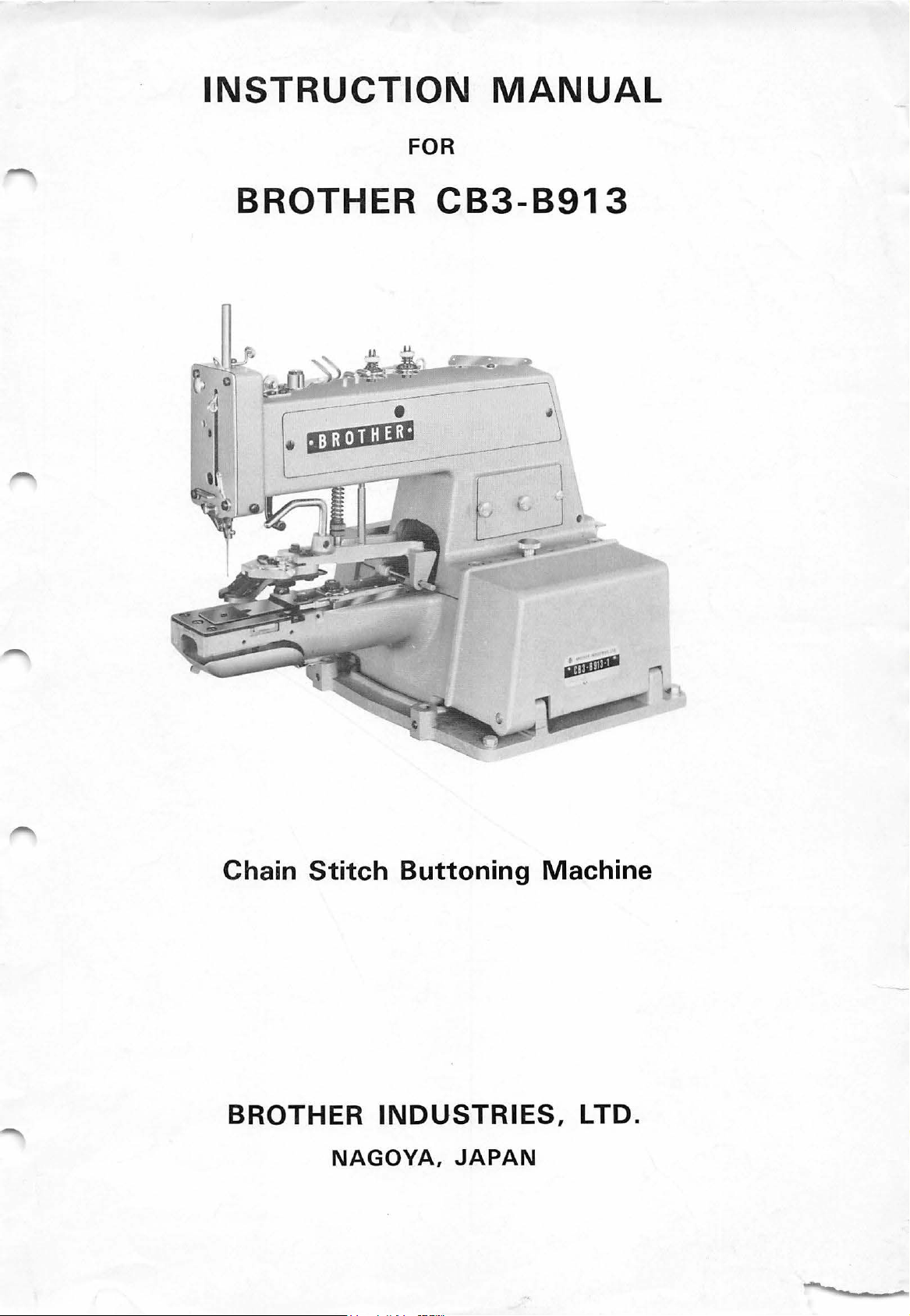
BROTHER
CB3-B913
Chain
BROTHER
Stitch
INDUSTRIES,
NAGOYA,
Buttoning
JAPAN
Machine
LTD.
Page 2
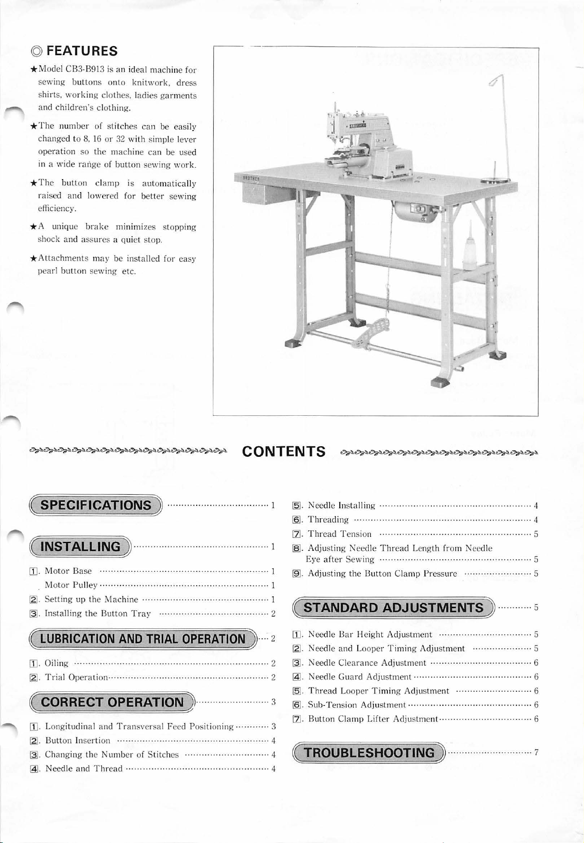
© FEATURES
* Model CB3-B913 is
sewing
shirts.
and children's clothing.
The number
*
changed to
ope
in a wide
*T
rai
efficiency.
* A
shock
*
Attachments may
pearl
buttons on
workin
ration
so
ran
he
button clamp
sed
and lowered
unique
and ass
button sewing
g c
lothe
of stitches ca
8.
16
or
the
machine can
ge
of
brake
ure
s a qui et stop.
an
ideal ma
to
s, l
32
with
butt
on sewing
I S
for
minimi
be installed fo r
etc.
chine fo r
knitw
ork.
adies gar
n be easily
simple le
be used
automatically
bett
er sewi
zes
stopping
dre
ss
ment
ver
work.
ng
easy
s
,:{l
.~
·-,·~J
u"
-i~
~
·
""'
( SPECIFICATIONS )
( INSTALLING )
[I].
Motor Base ......
Mot
or
Pull
ey
......
~
-
Sett
ing up
the Machine
~-
Install
ing the
(
LUBRICATION
[I]
. Oiling
[2]
.
Trial
Operati
........
Button
.. .. ..... ·
on
......... · ·
....
· · ..
.............
Tray ........................ · .. · ...........
AND
..... · .................... · ........
......
··
............ · .............................
.............
........
........
.....................
.. ·
.................
....
.....
....................................
TRIAL
OPERATION , ....
( CORRECT OPERATION )
. Longitudinal
~-
Button Inserti
~-
Chang
@.
Needle and
and
Tran
on
·· · ........
ing the Number
Thr
ead ...... ·
sversa
l Feed Positioning ·
· · · · ··· · .. · · · ·
of
Stitch
es
......
. ·
........
..............................
....
.....
...
.....
· · ........ · .... · ......
· .. ·· ·
.. · ........
·· .. ··
...... · ........
. ·· · .. · ·
...
.................
..........
.......
· ·
.. · ....
· .. · ·
....... ·
.......... · .....
......
......
........
....... 2
.....
....
· ... 4
· ·
1
~-
Needle Installing .
[Q].
T
hreading
[1]
.
Thread
. 1
~-
Adjusting ·
E
I
~
-
Adjust ing the
I
I
( STANDARD ADJUSTMENTS )
2
[D . Needle
2
~
-
Needle and Looper
2
~
-
Needle
@ . Needle
~
-
Thread
3
[Q].
Su
[1]
. Button C
( TROUBLESHOOTING )
··
. 3
4
4
ye
after
b-T
T ension
Sew
Bar
Clea
Guard
Looper
ension
lamp
......
...
................................... ····
.....
· · ..
.................
........ · .............. · ........
eed
le
Thre
ing · ·
.......
Button
Cla
Hei
ght
Adjus
Timing
ran
ce
Adjustme
Adjustment ................................
Timing
Adjustme
Lift
er
Adjustme
... ·
ad
Length fr om Needle
·· · · ·
......
mp Pressu
tment
Adjus
nt
......
Adjus
tment
nt
.........................................
nt
...........
· ... · · ·
......................
........................
···
.... · ......
·· ·
.........
··
· ... · · ·
.....
re
... · ....... · ..... · ......
tment
···
..................
· · · ....... · · ·
........................
..........
....
...........
. ·
·· ··· 4
·· ... ... 4
· .. ·
..
· ... 5
· ... · .. · · · ··· 5
............
.. ····
·· ..
· ..... 6
· .. · ...... 6
... 6
... 6
.........
···
·· .
........ 7
5
5
. 5
5
6
Page 3
( SPECIFICATIONS J
Sub-clas
Stitc
h type
Speed
Sewable
Numbe
Nee
dl e
Nee
dle
s - 1
button
size
r of stitches
bar
stro.ke
Single ch
single
8 to
2.5
TQ
TQ
ain
thread
30
mm in outside
to
6.5 mm in b
8, 16,
32
X 1 for A at button s
X 7 for
( INSTALLING J
[I]
.
Motor
In
case
shown below.
Power requirement
Base
of
using a comm
Single-ph
Three-pha
ase
se
ercial
s
motor,
I
stitch, single needle,
(JIS C
1,500 r
utton
I
48
mm
shank
butt
select one
Motor
4P,
250
W mot
4P,
250
W m
-2
ll)
pm
diam
eter
hole
6, 12,
ewing
on
se\\'ing
of those * In
or
oto
r
spac
24
ing.
Motor
(s
ingle-or
Belt
S
tit
Form
case
Button
cla
mp
lift S
thr
ee-phase)
diameter
Fla
t bu
tton
ch
Sha
nk
button
of
using a co mmercial table. dr
0
Lf)
4P, 250 W mo
6.5
0
U')
tandard
mm
¢ round
e
2
14
mm,
tor
ill
Maximum
leather
hol
belt
es
as shown below.
20
@
mm
Motor
Select the corr
which s
~
Source
frequen
50
Hz
60Hz
-
Setting
Pulley
ui
ts the power sour
cy
ect
motor pull
Machi
ne
speed
1,500
rpm
1,500 rpm
up
the
ey from
ce
frequency
Outside di
75
65
Machine
the table below
of
Mo
tor pull
ameter
mm
mm
your
area.
ey
Pulley
N-75 pulley
N-65 pulle y
0
0
N
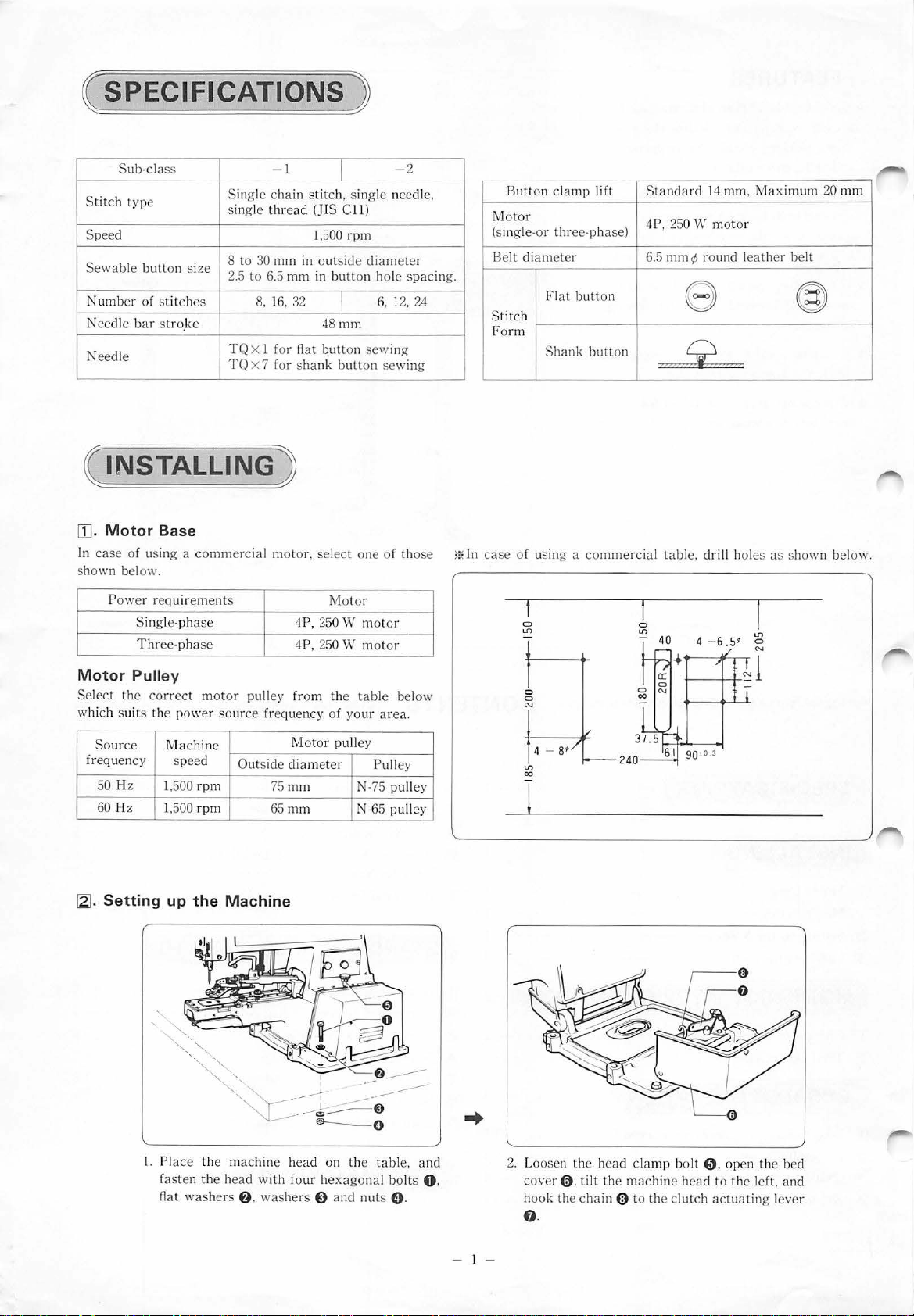
1.
-,.
U')
co
l.
Pl
ace
the
machin e
faste
n the head with four h
n
at
washe
rs
f)
.
was
head
her
s 0
on the t
exagonal bolt
and
nut
able
s 0 .
, and
s 0 .
- I -
2. Loosen
cover
ook th
h
f)
.
0 . tilt
the
head
clamp
the machine head
e chain (l) to the c
bolt 0 .
lut
ch
actuat
open th
to
the
e bed
left, and
ing l
ever
Page 4
~
-
Installing
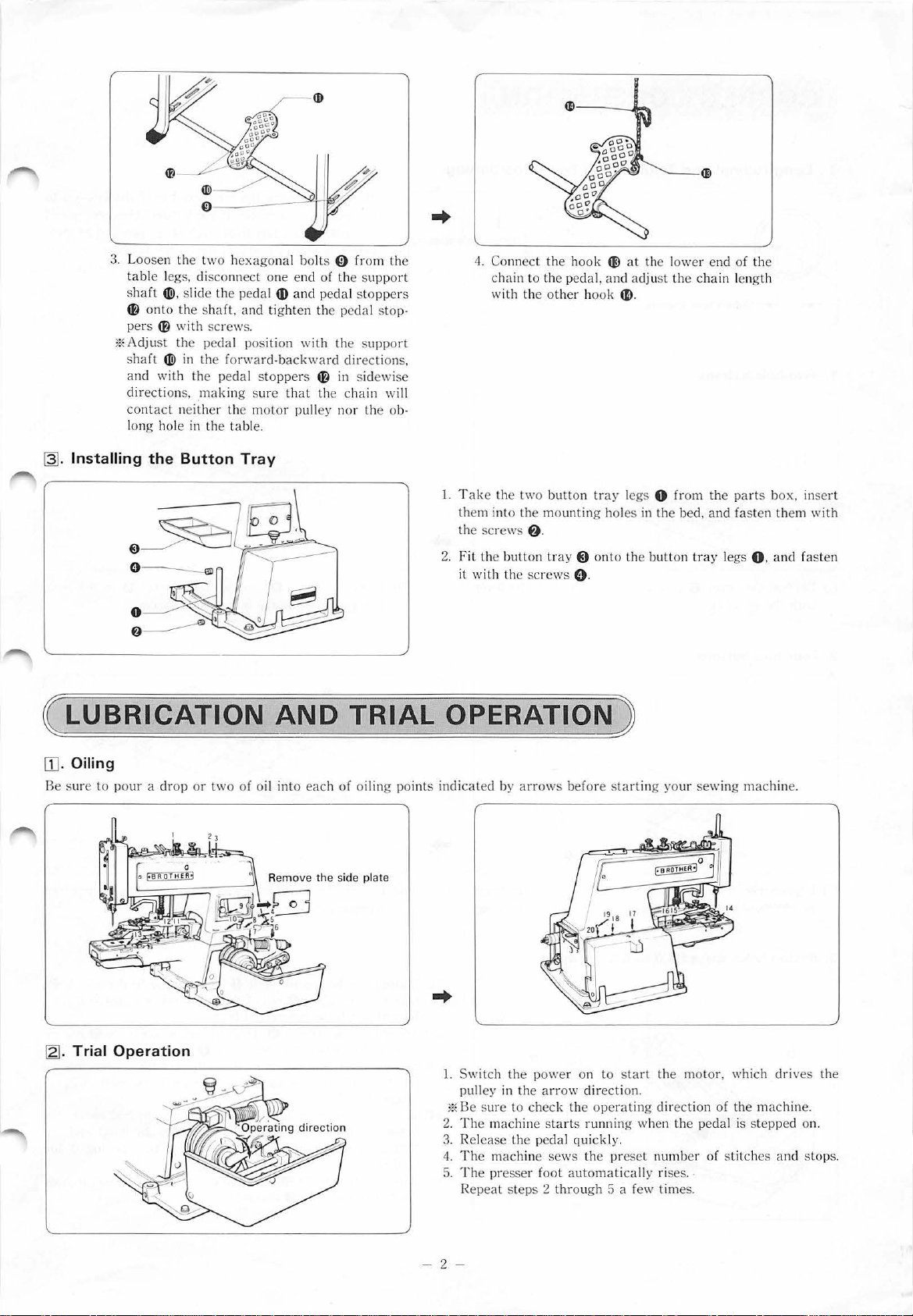
3.
Loosen
table legs, di
sh
~
pers ~ with screw
*A
s
and
direction
contact
l
ong
the
aft
4Ji)
, slide
o
nto
the shaft. and tig
dju
st the pedal position
haft
4Ji)
in
with
the
s,
.ma
neither the m
hole in the
the
Button
- Y
two hexagonal bolts 0 fro m
sconnect one
th
e pedal
s.
the
forward·backward
ped<
tl stoppe
kin
g s
tab
Tray
end
4D
and
hten
with the suppo
rs ~ in sidewise
ure
that
oto
r pulley nor the
le.
of the su
pedal stoppers
the p
edal stop·
directions,
the chain wi
the
pport
rt
ob·
ll
..
4.
Connect the hook
chain to the p
with
l.
T
ake the two b
them into the mo
the scr
2.
Fit the bu
th the sc
it wi
th
ews
tton
eda
e other hoo
utton tray legs
unting holes
f)
.
tray@ on
rew
s 0 .
til
at the lower end of
l, and
adjust
the c
k
41)
.
0 f
in
the
to
the
butt
on tr
hain lengt
rom the
bed,
and
ay legs
the
h
parts
box, inse
fas
ten
O. and fas
them
rt
with
te
n
( LUBRICATION
[1
].
Oiling
Be sure
~
-
Trial
to
pour
a dr
Operation
op
or
two
of o
AND
il into each
TRIAL
of
oiling poin
OPERATION)
ts
indi
cated
by
arrows before startin
1.
Switch
pulley in
*Be sur
2. The machine starts running when
3.
Release the p
4.
The machine
5. The presser fool
R
the powe
the arrow direc
e to check the op
epea
t steps 2
r on
eda
l quickl y.
sews
automaticall
thr
ough 5 a f
to start
the
tion.
erat
preset
g yo
ur sewing machine.
the m
oto
ing direc
ew
the
number
y ri
ses
times.
tion
. .
r, which dri ves
of the machine.
pedal is
of sti
step
tch
es and stops.
the
ped on.
- 2 -
Page 5

( CORRECT OPERATION)
[
[].
Longitudinal
and Transversal
Feed
Positioning.
1 .
Two-hole
(1
) Depress the l
with the
Button hole spacing
button
s
ever
0 and align the
©mari
e
arr
ow on the lever
Be sure to check the hole spacing of th e but
be sew n on
2.5 to
tioned in steps 1 and 2. If the
4.0 to 6.5 mm a
and 3.
(2) Loosen the nut
tion representing the bu
to
4.0 mm a
a fabric.
part
from
par
t from
f)
, and
If
the bu
tto
eac
h other. proceed as men·
butt
each ot
set
the pointer $ to the posi-
tto
n hole spacing.
ton
s to
n hol
es
are spaced
on holes are sp
her. take steps 1, 2
ace
d
2. Four-hole
(1) Depress the lever 0 and move
to th e posit ion representing the bu
3.
Button
buttons
holes spaced 4 .0
to
th
e arrow on the lever
tt
on hole spacing.
6.5
mm
apart
.
..
(2
) Loosen the
pr
esenting th e button hole spaci ng.
re
(1) Loosen the he
tak
e the feed pl
porarily with the he
(2
) Loosen the set screw 0 . push the adjusting plate 0 a
wa
y,
and retighten the set screw 0 .
(3
) Set the lever and the poin ter to the positions representing
the button hole sp
gra
phs 1 and 2.
4)
With the power switch
(
press the pedal,
that the needle wi
feed
pl
ate.
(5
) Aft
er
the feed p
the h
exago
xago
nal bo
nut
f)
, and set the pointer 8 to the pos
nal bolt 0 . remove the feed plate A
ate
8 out of the pa
xag
onal bolt.
ac
ing in the manner mentioned in Para·
OFF
turn
the machine pulley by hand and
ll
not hit the edges of the opening in the
lat
e 8 h
as
been correctly positioned, tighten
lt
0 sec
urely.
rt
s box,
, open the
rig
and
ht
install
bed
cov
it
ion
f)
it
tem·
ll
the
er, de·
see
,
- 3 -
Page 6

IZJ.
Button Insertion
3.
1 . Two-hole buttons.
2.
Four-hole buttons.
Sewing
continually.
on
same-sized buttons
•
0
0
(1) When the cam plate 0 is pushed, the button clamp 8 opens. Insert a button into the button clamp,
(2)
Insert a button into the clamp in the correct direction as shown above, and re- and make sure
lease the cam plate
0.
securely gripped. With the button gripped by the clamp, loosen the set screw
•.
pull the adjusting plate e toward
yourself until there is a clearance of
about
0.5
ing plate e and the screw
Then tighten the set screw
to
1.0
that
the button has been
mm
between the adjust-
•.
@).
~-
Changing the Number of Stitches.
Turn the power switch OFF
a desired number of stitches
~-
Needle and Thread
Needle
Size of thread Kind of thread
#
100
to
80
60
40
30
30
to
to
to
to
to
;1:80
#60
#40
#30
#24
;!:
16
# 9
#11
#14
#16
#18
#20
#
#
#
#
#
at
the normal machine stop position, open the left bed cover, and depress the pedal
as
follows.
Cotton, silk
II
II
II
II
,
II
II
II
II
II
~-
Needle Installing
as
you select
1 . 8 stitches
The figure
2.
1 6 stitches
at
left shows the case of 8 stitches.
Pull the stitch select knob 0 toward yourself and
in
move it
3.
32
(1) Pull the stitch select knob 0 toward yourself
the arrow direction.
stitches
and move it in the arrow direction.
(2)
Loosen the hexagonal bolt
@)
in
lever
the hexagonal bolt
1§1.
the arrow direction, and retighten
fj.
Threading
fj,
push down the
Pull the thread whtJe pressmg the button.
Select a needle and thread by referring
to the above table.
3*
Use a TQ X 1 needle for sewing flat
buttons on ; a TQ
X 7 needle for
shank buttons.
Hold the needle with its long groove
side
0 facing
sert the needle into the needle
hole all the way, and clamp
the screw
in
8
your direction,
it
in-
bar
with
-4-
Page 7
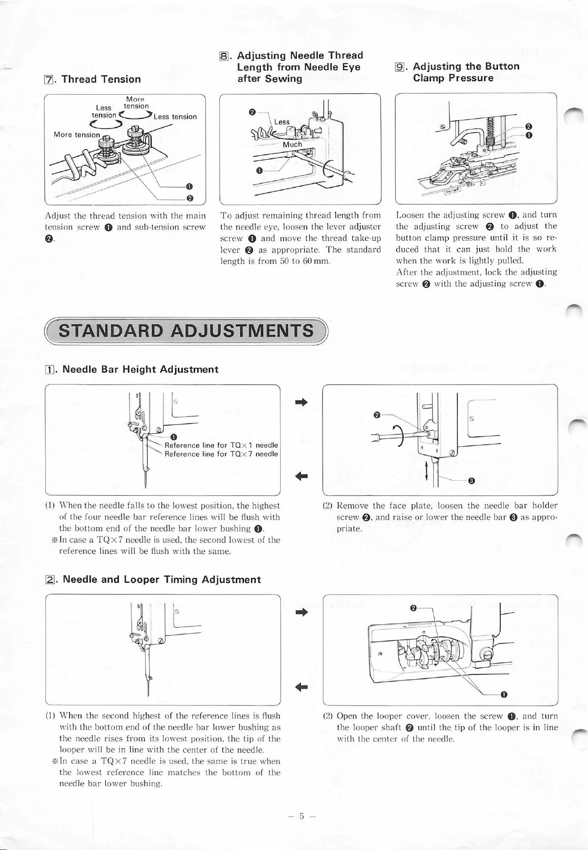
[ZJ
.
Thread
CJ
Tension
ss
Le
tension
MorP.
tension
<.____>L
ess tension
~a~.
Adjusting
Length
after
Needle
from
Sewing
Thread
Needle
Eye
~.
Adjusting
Clamp
the
Button
Pressure
@
0
Adju
st the
thread
tension with the main
tension screw 0
f).
(
sTANDARD
[[]. Needle
(I)
When the needle falls
of the four
the
bott
l?<
In case a TQ
refere
nce
and
Bar
Height
nee
dle
om end of the need le bar lower bushing 0 .
X 7
ne
lines will
sub·ten sion sc
ADJUSTMENTS
Adjustment
L
·-
o
Reference line
Re
ference line for TQx 7 needle
to
the lowest position.
bar
reference lin
edle is used,
be
flu
sh with the same.
To
adju
rew
the
needle
screw 0 an
lever
length is from
for
TQ x 1 needle
the
es
will
be
the second lowe
st
f)
high
flu
sh with
st
remaining
eye
. loosen the l
d move the
as ap
propr
50
est
of
the
thread
thread
iate. The st
to
60 mm.
)
(2
up
d
.. and
Loosen the
the
b
utt
on cl
duc
ed
when the
After
sc
rew 8 with
rai
se
len
gth from
ever adjuster
take·
andar
) Remove the face plate, loosen the needle
scr
ew
f)
priate.
adjusting
adjusting
amp pressure
that
work
the adju
or l
ower
scr
ew
it
can
just
is lightly pulle
stment. l
the
adjusting scr
the
needle
screw
f)
to
unt
hold
ock the
bar~
il it is
0 ,
and
adju
st
so
the
work
d.
adjusting
ew
0 .
bar holder
as
appro·
turn
the
re·
12]
.
(I)
When the
wi
th
ooper
l
mIn ca
th
need le b
Needle
th
e needle ri
e lowe
and
Looper
second
the bott
se a TQ
om
end
ses
from its l
will be in line wi
x 7 needle is used.
st
reference line
ar lower
Timing
highest of the ref
of the needle b
owes
t pos
th
the cent
match
bushing.
Adjustment
erence
lines is
ar lower
ition.
the
er
of
the need
the same
es
is true when
the bott
bushing
tip
of the
le.
om
of
flu
sh
as
the
- 5 -
(2)
Open the looper cover, loosen the screw 0 . and turn
the looper shaft
the
with
center
f)
until th
e.
of the needle.
tip
of
the
looper is
in
line
Page 8

~-
Needle Clearance
Adjustment
Loosen the set collar screw 0 and move
the looper to adjust the clearance
tween the needle arid the tip of the looper
to
0.03
to
0.08
mm when the tip of the
in
looper is
needle.
line with the center of the
be-
~-
Needle Guard Adjustment
Loosen the screw
guard
0 to adjust the clearance between
the needle and the needle guard
about
0.1
mm.
f)
and move the needle
0 to
~-Thread
Looper Timing
Adjustment
1.
Loosen the screw
reference line on the groove cam
with
that
on the looper shaft
2.
Loosen the screw
reference line on the thread looper
triangle cam
shaft
f).
8 with
O.
and align the
8.
and align the
that
on the looper
f).
8
!§].
Sub-Tension Adjustment
Reference line
1.
Check to see
on the needle
matches the reference line on the
needle
these reference lines
make an adjustment by loosening the
hexagonal bolts
that
bar
bar
drive lever shaft
8 and
the reference line
drive lever 0
are
unaligned,
8.
f).
If
0
0
2.
Turn
the pulley by hand to raise the When raising
needle
bar
until the top of the needle clamp by means of the pedal.
bar
0 is
44
to
48
end of the needle
0.
At
this time, the tension disc must
begin to float. Loosen the screw
and turn the sub-tension stud G until
the above-mentioned timing
tained.
*In
case a TQ X 7 needle is used, the
tension disc must begin floating when
the top of the needle
58
mm above the top of the needle
upper bushing.
To decrease
mm above the top
bar
upper bushing hole
bar
is
IZJ.
Button Clamp Lifter
Adjustment
----~-=--a.:~~
·-~~
or
lowering the button
1.
Remove the screw
f),
and retighten the screw
2.
Hook the chain 8 into the hole
8
is
ob-
54
to
bar
button clamp connecting rod
*The
pedal and chain
0.
move it into the
are
optional.
e.
in
0.
the
-6-
Page 9

{
TROUBLES~OOTIN
_
G )
Trouble
Needle breaks.
Stitches ski p.
I
Cause
I
Button ins
improperly.
Longitudinal
and point
improperly.
Wrong
timing. timing.
Wrong nee
l
ooper
T
oo
between nee
looper.
Need le
incorrect.
T
oo
be
tween need
needle
erted
feed
er pos
ition
thread loop
dle and Needle and looper Adju
timing. timing. looper timing.
g r
·eat a clearance
dle
and
bar
hei
ght
g reat a c le
guar·d.
le a
aranc
lever
er
nd
I
ed
e
Check point
I
Button hole
Longitudin al feed l
and pointer positions.
Thr
ead looper
Needle
Needle
Clea rance between
needle
dir
clearanc
bar
height.
and
needle guard.
ection. h
timing.
e.
ever
I I
Inse
oles are
direction.
Adju
f
eed
to butt
Adjust
Adjust
betwe
l
oope
Adjust needle ba r
height.
Adju
Remedy
rt
button
so
in
the
st lo n g
itudin
lever and poin
o n hole s p
thread
loop
st needle and
c le
aran
needle
ce
gua
e n needle and
r.
st
its
correct
a l
ter
acing.
er
rd.
I
Page
l
Stitch
es
Thr
ead breaks.
loose.
Remaining
length too short. length.
Sub-tension di
improperl
Sub
-tension too weak. Sub-tension tensio
Needle installed
inc
orrectly.
Sub-tension di
timing
Needle too thin for
thread.
thread
sc
floats
y.
sc float
wr
ong. timin g.
Remai ning thread
Ten
Needle
Tension disc
Need le
sion di
dire
and thea
sc
ction.
float.
flo
at
cl.
Adjust remainin g
t
hread len
Adjust s
float.
n.
Adju
tension.
Install needle
long g r·
fron
Adju
R
efer
for need le
gth
ub-tension disc
st
sub-tension
oove
t.
st
facin
sub-tens ion.
to inst
ructions
and
.
with
thr
g
its
ead
.
-
7-
Page 10

~--·
•.
118-913
192913-1-02
Printed in Japan
 Loading...