

Page 1
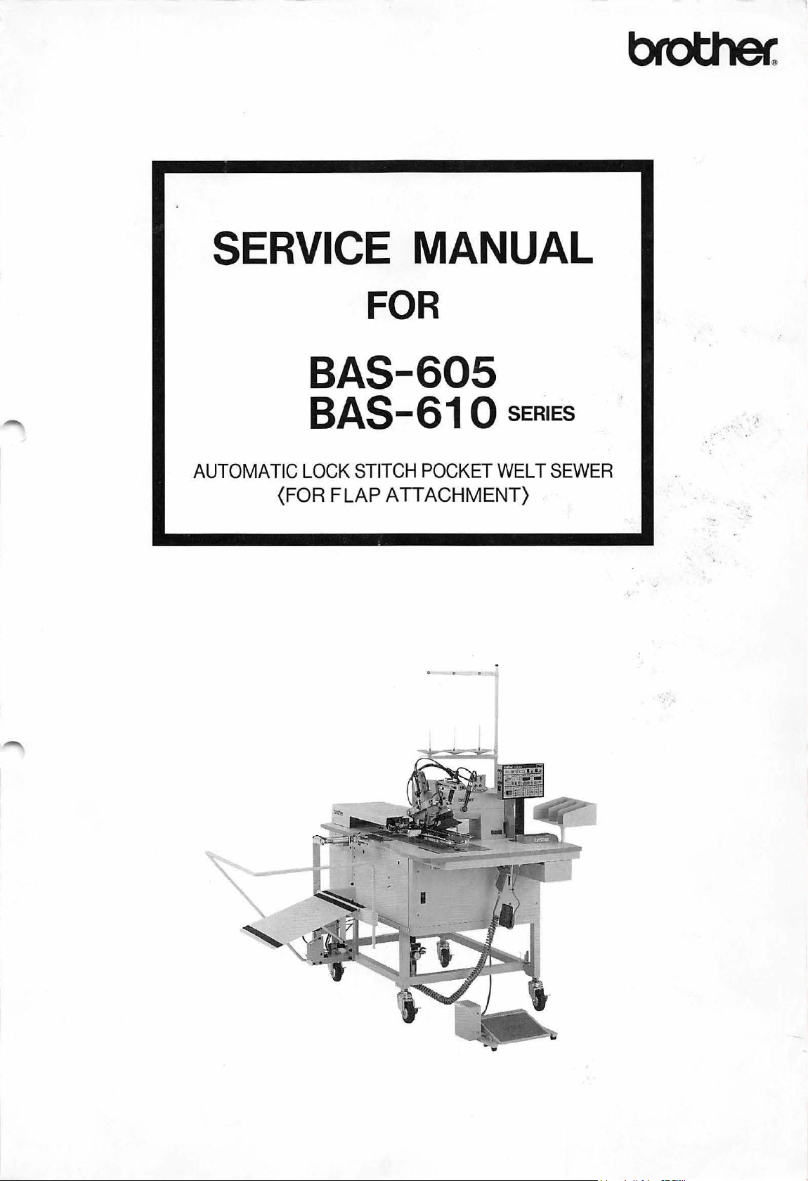
SERVICE MANUAL
FOR
BAS-605
AUTOMATIC
(FOR FLAP ATTACHMENT)
BAS-61 0
LOCK
STITCH
POCKET
SERIES
WELT
SEWER
Page 2
CONTENTS
(
SEWING
I]] Sewing machine specifications . . . . . . . . . . . . . . . . . . . . . . . . . . . . . . . . . . . . . . . . . . . . . . . . . . . . . . . . . 1
~
(
INSTALLATION
rn
~
(
LUBRICATION
I]] Lubrication . . . . • . . . . . . . . . . . . . . . . . . . . . . . . . . . . . . . . . . . . . . . . . . . . . . . . . . . . . . . . . . . . . . . . . . . . . . 7
~
(
OPERATION
MACHINE
Specification comparative
SPECIFICATIONS
) · · · · · · · · · · · · · · · · · · · · · · · · · · · · · · · · · · · · · · · · · · · · · · · · · · · · · · · · · · · · · · · · · · · · · 4
Installing
Attachingtheairtubes
the
stacker
..................................................................
................................................................
) · · · · · · · · · · · · · · · · · · · · · · · · · · · · · · · · · · · · · · · · · · · · · · · · · · · · · · · · · · · · · · · · · · · · · · · 7
Oiling
................................................................................
)
···························
table
) · · · · · · · · · · · · · · · · · · · · · · · · · · · · · · · · · · · · · · · · · · · · · · 1
. . . . . . . . . . . . . . . . . . . . . . . . . . . . . . . . . . . . . . . . . . . . . . . . . . . . . . . . 3
· ·
········ · ········ · ·······
·· ··
··········
· · ·
··
4
6
8
9
I]]
Marking
(
SEWING
[]]
Backtacking (N} (Rear reference position)
~
Backtacking
liD
Backtacking (V)(Rear reference position)
1!1
Backtacki
[§] Condensed stitching (Rear reference position)
III Condensed stitching (Front
(
SEWING
I]] Backtacking (N)
~
Backtacki
liD
Condensed stitching
1!1
Backtacking (slant) BAS-612
(
DISASSEMBLY
light
.........................................................................
FLOWCHART
(N)(Front
ng
(V)(Front
FLOWCHART
..................................................................
ng
(V) . . . . . . . . . . . . . . . . . . . . . . . . . . . . . . . . . . . . . . . . . . . . . . . . . . . . . . . . . . . . . . . . . . . . . . 18
) · · · · · · · · · · · · · · · · · · · · · · · · · · · · · · · · · · · · · · · · · · · · · · · · · · · · · · · · · · · · · · · · · · · · · ·
BAS-605, 606 ) · · · · · · · · · · · · · · · · · · · · · · · · · · · · · · · · · · · · · · · · · · · · · · · ·
or
center reference position) . . . . . . . . . . . . . . . .
or
center reference position) .
or
center reference position) . . . . . . . . . . . . . . . . . . . . . . . . . . . . . . . . .
BAS-610, 611, 612 ) · · · · · · · · · · · · · · · · · · · · · · · · · · · · · · · · · · · · · · · · · · · ·
...................................................
...........................................................
..............................................
..
. . .
..
. . .
..
.. . ..
. . .
..
..
..
. . .
..
.. ..
..
. .
..
. .
..
. . .
..
.. . ..
..........................................
..
. . . . . . . .
. . . . .
..
. .
..
. . .
·
...............
.. ..
..
.. ..
. .
. . . . . .
..
. . . . . 14
:
...
9
11
11
12
13
15
16
17
17
19
20
21
I]] Preparations
~
Removing
liD
Removing
1!1
Removing
[§] Removing
III Removing
Removing
Ill
Removing
for
disassembly . . . . . . . . . . . . . . . . . . . . . . . . . . . . . . . . . . . . . . . . . . . . . . . . . . . . . . . . . .
the
cloth
guide
(left)
the
binder
the
face
the
machine head . . . . .
the
carriage feed mechanism . . . . . . . . . . . . . . . . . . . . . . . . . . . . . . . . . . . . . . . . . . . . . . . . 26
the
feed mechanism . . . . . . . . . . . . . . . . . . . . . . . . . . . . . . . . . . . . . . . . . . . . . . . . . . . . . . . . 27
the
padding cloth presser assembly . . . .
.................................................................
plate
..............................................................
. . . . . . . . . . . . . . . . . . . . . . . . . . . . . . . . . . . . . . . . . . . . . . . . . . . . . . . 23
..
. . . . . . . . . . . . . . . . . . .
..
..
. . . . . . . . . . . .
. . . . . . .
.. . ..
. . . .
..
. . . . . . . . . . . . .
MODEL
.. . ..
No.
..
..
. . .
.. .. . ..
BAS-605,
21
23
24
..
25
. . 28
610
SERIES/
Page 3

(
ASSEMBLY
) · · · · · · · · · · · · · · · · · · · · · · · · · · · · · · · · · · · · · · · · · · · · · · · · · · · · · · · · · · · · · · · · · · · · · · · · · ·
29
[I] Attaching
IZ1
Attaching
@1
Attaching
00
Attaching
[§]
Attaching
liD
Attaching
!I1
Attaching
00
Attaching
[11
Attaching
1iDJ
Other . . . . . . . . . . . . . . . . . . . . . . . . . . . . . . . . . . . . . . . . . . . . . . . . . . . . . . . . . . . . . . . . . . . . . . . . . . . . . . . 38
(
STANDARD
[]]
Adjusting
IZ1
Adjusting
@]
Adjusting
00
Adjusting
[§]
Adjusting
liD
Adjusting
!I1
Adjusting
00
Adjusting
[11
Adjusting
liDJ
Adjusting
Ill!
Adjusting
Hi~
Adjusting
~
Adjusting
Ml
Adjusting
H§l
Adjusting
Hm
Adjusting
Ill!
Adjusting
lift!
Stacker operation . . . . . . . . . . . . . . . . . . . . . . . . . . . . . . . . . . . . . . . . . . . . . . . . . . . . . . . . . . . . . . . . . . . .
Ill Adjusting
181
Adjustingtheflapsensor(BAS-611,612)
~ Carriage feed step operation . . . . . . . . . . . . . . . . . . . . . . . . . . . . . . . . . . . . . . . . . . . . . . . . . . . . . . . . . .
IDl
Error codes (BAS-605, 606) . . . . . . . . . . . . . . . . . . . . . . . . . . . . . . . . . . . . . . . . . . . . . . . . . . . . . . . . . . . .
Error codes
1211
Initializing
~
DIP
~
110
checking
the
feed mechanism assembly . . . . . . . . . . . . . . . . . . . . . . . . . . . . . . . . . . . . . . . . . . . . . . .
the
machine head
the
face plate . . . . . . . . . . . . . . . . . . . . . . . . . . . . . . . . . . . . . . . . . . . . . . . . . . . . . . . . . . . . . .
the
binder . . . . . . . . . . . . . . . . . . . . . . . . . . . . . . . . . . . . . . . . . . . . . . . . . . . . . . . . . . . . . . . . .
the
doth
guide . . . . . . . . . . . . . . . . . . . . . . . . . . . . . . . . . . . . . . . . . . . . . . . . . . . . . . . . . . . . .
the
movable knife assembly . . . . . . . . . . . . . . . . . . . . . . . . . . . . . . . . . . . . . . . . . . . . . . . . . 34
the
bobbin thread knife assembly . . . . . . . . . . . . . . . . . . . . . . . . . . . . . . . . . . . . . . . . . . . .
the
carriage feed mechanism . . . . . . . . . . . . . . . . . . . . . . . . . . . . . . . . . . . . . . . . . . . . . . . . 36
the
padding cloth presser
ADJUSTMENT
the
upper and
the
clearance between
the
clearance between
the
needle bar
the
clearance between
the
carriage feed mechanism
the
binder
the
doth
the
thread take-up (Required
the
center knife assembly . . . . . . . . . . . . . . . . . . . . . . . . . . . . . . . . . . . . . . . . . . . . . . . . . . .
the
movable
the
bobbin thread
the
corner knives . . . . . . . . . . . . . . . . . . . . . . . . . . . . . . . . . . . . . . . . . . . . . . . . . . . . . . . . . . .
the
padding cloth presser
the
tension release
the
pickup stacker . . . . . . . . . . .
the
bar stacker
the
foot
(BAS-61
the
memory
switch settings (BAS-605, 606) . . . . . . . . . . . . . . . . . . . . . . . . . . . . . . . . . . . . . . . . . . . . . . . . . . . . .
.........................................................................
.................................................................
guide
knife
switch
0 series) . . . . . .
..........................................................
foot
spring . . . . . . . . . . . . . . . . . . . . . . . . . . . . . . . . . . . . . . . . 38
) · · · · · · · · · · · · · · · · · · · · · · · · · · · · · · · · · · · · · · · · · · · · · · · · · · · · · · · · ·
lower
shaft
timing
the
needle and the rotary hook . . . . . . . . . . . . . . . . . . . . . . . . .
the
rotary
lift
stroke and
the
rotary hook and
.............................................................
assembly
knife
assembly . . . . . . . . . . . . . . . . . . . . . . . . . . . . . . . . . . . . . . . . . . . .
foot
..
. . . . . . .
.............................................................
(BAS-61
...............................................................
0,
611, 612)
..
. . . . . . . . . . .
............................................
hook
and
the
needle plate . . . . . . . . . . . . . . . . . . .
the
needle bar height . . . . . . . . . . . . . . . . . . . . . . . . . . . .
the
bobbin
................................................
to
assure thread remainder
.................................................
spring .
.. . ..
.. ..
...............................................
.. . ..
..
. . . . . . . . .
..
. . . . . . .
..
..
..
..
. . . . . . . .
.. . .. ..
.. . ..
. .
.. . .. . ..
..
case
opener . . . . . . . . . . . . .
for
sewing start.)
. . .
..
.. .. ..
..
. .
..
. . . . . . . . . . . . . . . . . . .
. . . . .
..
..
..
..
. . . . . . . . .
..
..
..
. . . .
.. . .. ..
. . . .
. . . . .
..
..
..
. .
. . . .
. .
..
..
..
..
. . . . .
..
. . . . . . .
. .
..
.. . ..
..
. . .
..
..
..
. . . 80
29
31
32
33
33
35
39
39
39
40
40
40
41
45
46
47
47
52
55
58
65
66
67
72
73
. 7 4
75
78
79
81
82
87
'
MODEL
No.
BAS-605,
610
SERIES
Page 4
( STANDARD ADJUSTMENT [ELECTRONIC PORTION] ) · · · · · · · · · · · · · · · · · · · · · · · · · · · · · 88
ill
Replacing
~
Replacing
(
OPTIONALPARTSINSTALLATION)
ill
Flap
~
Spacerfor
00
Hand switch . . . . . . . . . . . . . . . . . . . . . . . . . . . . . . . . . . . . . . . . . . . . . . . . . . . . . . . . . . . . . . . . . . . . . . . . .
!!I
Marking
[§]
Thread breakage
[§]
Lower feed device . . . . . . . . . . . . . . . . . . . . . . . . . . . . . . . . . . . . . . . . . . . . . . . . . . . . . . . . . . . . . . . . . . . .
111
Pedal . . . . . . . . . . . . . . . . . . . . . . . . . . . . . . . . . . . . . . . . . . . . . . . . . . . . . . . . . . . . . . . . . . . . . . . . . . . . . . .
Ill
Air
ejector
~
Darts stretcher assembly . . . . . . . . . . . . . . . . . . . . . . . . . . . . . . .
!iDl
Replacing
guide
lights
the
circuit board
the
fuse
...................................................................
. . . . . . . . . . . . . . . . . . . . . . . . . . . . . . . . . . . . . . . . . . . . . . . . . . . . . . . . . . . . . . . . . . . . . . . . . .
working
the
while
.......................................................................
detector
..........................................................................
gauge . . . . . . . . . . . . . . . . . . . . . . . . . . . . . . . . . . . . . . . . . . . . . . . . . . . . . . . . . . . . . . .
...........................................................
····
········
standing
. . . . . . . . . . . . . . . . . . . . . . . . . . . . . . . . . . . . . . . . . . . . . . . . . . . . . . . . . . . .
up
. . . . . . . . . . . . . . . . . . . . . . . . . . . . . . . . . . . . . . . . . . . . . . . . .
········· · ·········
..
. . . . . . . . . . . . . . . . . . .
·····
············
..
. . . . . . . .
88
93
95
95
95
96
96
97
97
97
98
99
103
( TROUBLESHOOTING GUIDE )
(ERROR
CODES)····································································
······
· ·
·········· · ······· · ·······
· ·
··
··········
·····
( CONTROL CIRCUIT BLOCK DIAGRAM ) · · · · · · · · · · · · · · · · · · · · · · · · · · · · · · · · · · · · · · · · · · ·
106
113
123
MODEL
No.
BAS-605,
610
SERIES
Page 5
(
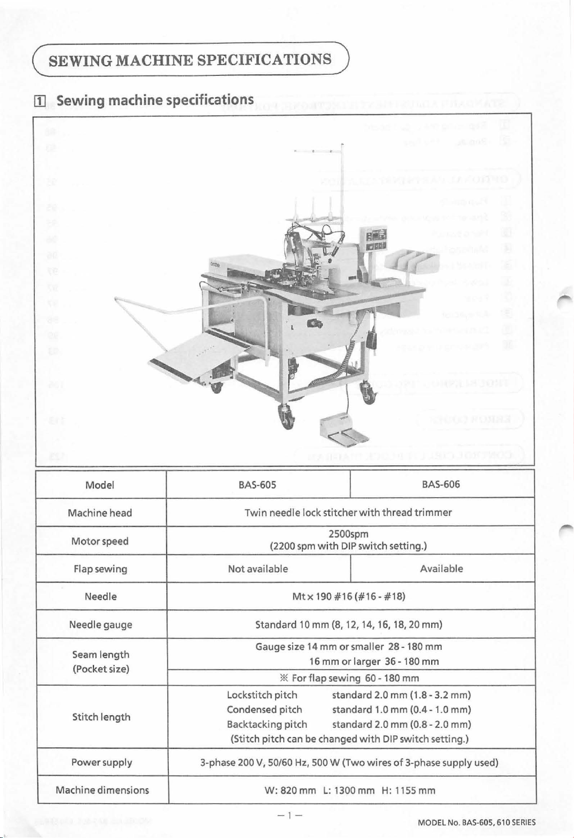
SEWINGMACHINESPECIFICATIONS)
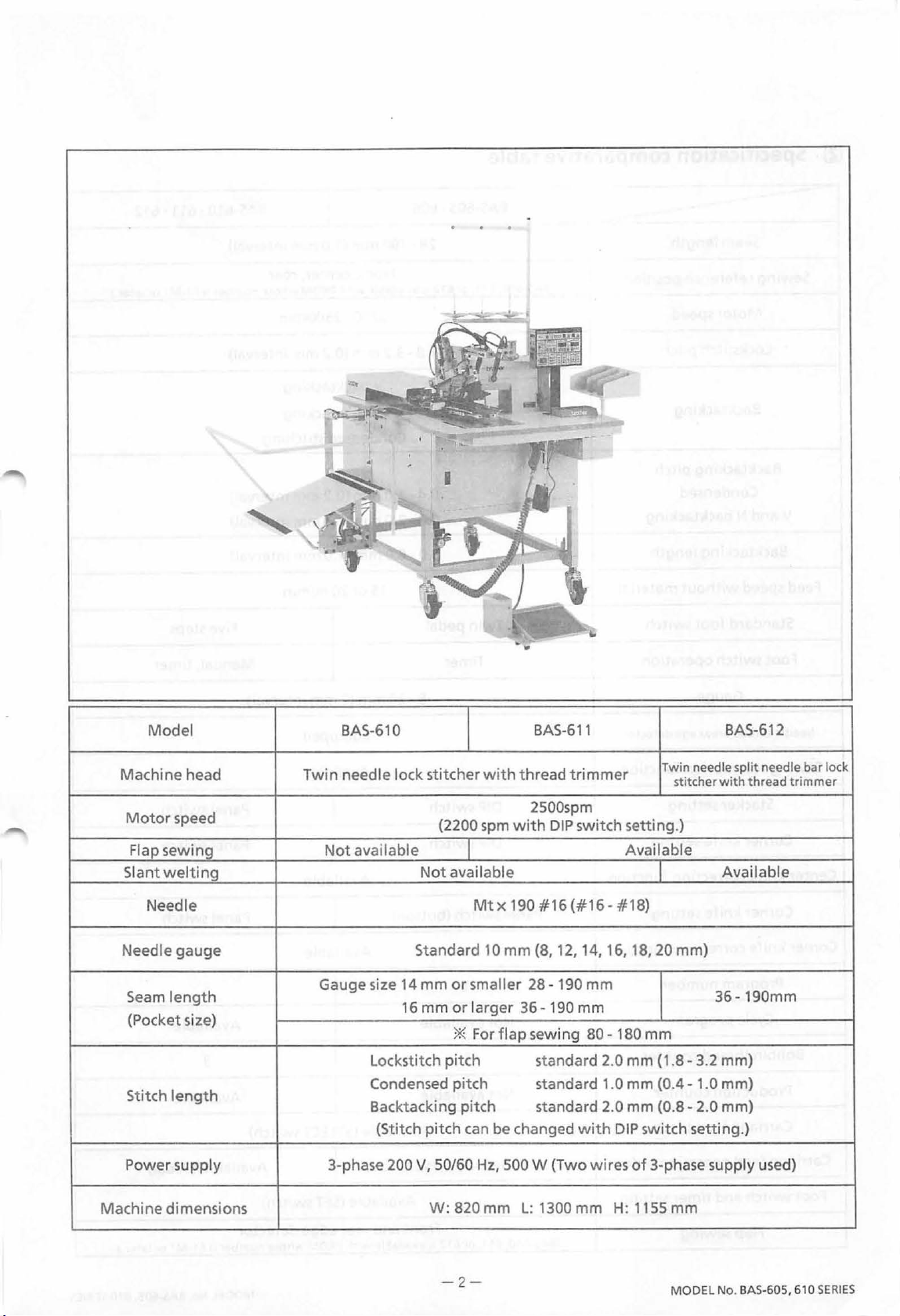
11J
Sewing
machine
specifications
Model
Machine head
Motor
Needle gauge
speed
Flap sewing
Needle
.·
~
' A·
...
Not
BAS-605
Twin needle lock stitcher
2500spm
(2200
spm
with
available
Mtx
190#16(#16-#18)
Standard
10
mm (8,
with
thread t
DIP
switch setting.)
12,
14,
16, 18,
BAS-606
rimmer
Available
20
mm)
Seam
length
(Pocket size)
length
Stitch
Power supply
Machine dimensions
Lockstitch pitch
Condensed pitch
Backtacking pitch
(Stitch pitch
3-phase 200
Gauge size
V,
50/60Hz,
W:
-1-
14
mm
16
mm
*
Forflapsewing
can
be
changed
500
820 mm
L:
or
smaller
or
larger
standard 2.0 mm (1.8-3.2 mm)
standard
standard
with
W (Two wires
1300 mm
28-180
36-
60-180mm
1.0 mm
2.0 mm (0.8-2.0 mm)
DIP
of
H:
mm
180
mm
(0.4-
1.0 mm)
switch setting.)
3-phase supply used)
1155 mm
MODEL No.
BAS-605,
610
SERIES
Page 6
Model
BAS-610
BAS-611
BAS-612
Machine head
Motor
Slant
Needle
Power supply
Machine dimensions
speed
Flap sewing
welting
Needle
gauge
Seam
length
{Pocket size)
Stitch
length
Twin
needle lock stitcher
Not
available Available
Gauge size 14 mm
16 mm
Lockstitch pitch
Condensed pitch
Backtacking pitch
{Stitch pitch
3-phase
200
with
thread
spm
{2200
Not
available
Standard
or
or
*
can
V,
50/60Hz, 500 W (Two wires
W:
820 mm
with
Mt X 190 # 16
10
mm (8, 12,
smaller
larger
36-190
Forflap
be changed
L:
trimmer
2500spm
DIP
switch setting.)
( #
28-
190
mm
sewing
standard
standard
standard
with
1300
mm
Twin needle split needle bar lock
stitcher
16
- #
18)
14,
16, 18, 20 mm)
mm
80-
180 mm
2.0 mm
1.0 mm (0.4- 1.0 mm)
2.0 mm (0.8- 2.0 mm)
(1.8-
3.2 mm)
DIP
switch setting.)
of
3-phase supply used)
H:
1155 mm
with
thread
Available
36-190mm
trimmer
-2-
MODEL No. BAS-605,
610
SERIES
Page 7
~
Specification comparative table
--------
Sewing reference position
Feed
Seam
length
Motor
Lockstitch pitch
Backtacki ng pitch
V and N backtacking
Backtacking
speed
Standard
Foot switch operation
speed 2200 · 2500spm
Backtacking
Condensed
length
without
foot
material
switch
BAS-605
(BAS-610, 611,
Twin pedal
Timer
or
612
• 606
28-190
is
1.8-3.2
0.4-
0.8-
3.0-6.0
mm (1.0 mm interval)
Front, center, rear
available
with
PROM whose
mm (0.2 mm interval)
V backtacki ng
N backtacking
Condensed stitching
1.0 mm (0.2 mm interval)
2.0 mm (0.4 mm interval)
mm
(1.0 mm interval)
15
or
20m/min
BAS-610 • 611
number
is
61-M1
Five steps
Manual,
timer
• 612
or
later.)
Gauge
Needle
thread
breakage
Sewing resumption
Stacker setting
Corner
Center
Corner
Corner
Bobbin thread counter
Production counter
Carriage feed
knife
knife
correction
knife
knife
correction
Program
Cycle program
detector
function
DIP
switch
DIP
setting
function
setting Panel switch (button)
function
number
timer
switch
1 5
Not
available
1 3
Not available Available
8-20
mm
Equipped
Available
Available
Available
Available
{2
mm interval)
(SELECT
switch)
Panel switch
Panel switch
Panel switch
Available
Carriage feed
Foot switch and
operation
timer
Flap sewing
order
setting Available
Available
(BAS-610,
(THREAD TRIMMER switch) Available (Pedal)
611,or
Front and rear edge detector
612
isavailablewith
(SET
PROM
-3-
switch)
whose
number
is
61-M1
or
later.)
MODEL No. BAS-605, 610
SERIES
Page 8
c
INSTALLATION)
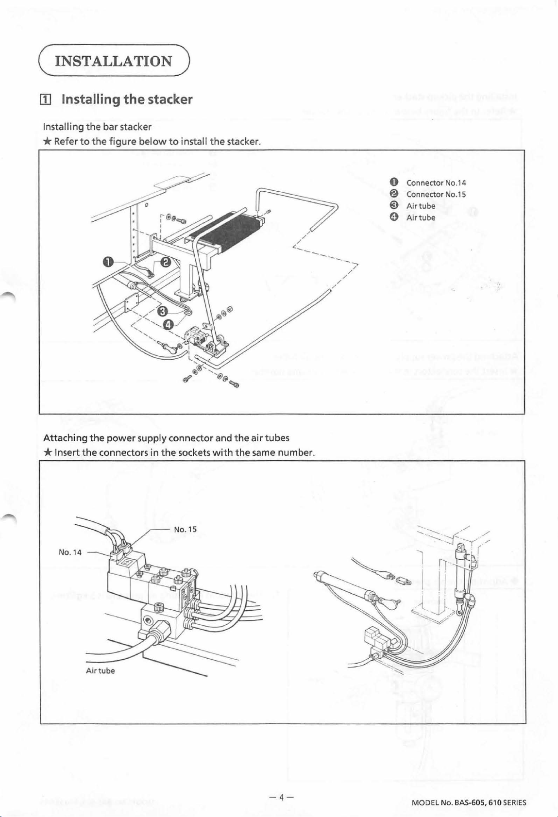
[I]
Installing
In
stalling
*Refer
the
to
the
the
bar
stacker
figure below
stacker
to
install
the
stacker.
Attaching
*
Ins
ert
the
power
the
connectors in
supply connector
the
sockets with
and
the
air
tubes
the
same number.
/
.::
__
/
/
--
---/
Connector
0
@
Connector
@)
Air
Air
e
/
/
No.14
No.15
tube
tube
- 4 -
MODEL No. BAS-605,
610
SERIES
Page 9
Installing
* Refer
the
pickup stacker
to
the
figure
below
to
install
the
stacker.
0 Connector No.14
@ Connector No.15
@)
Airtube
0
Airtube
Attaching
*Insert
+Adjusting
the
the
power
connectors in
the
air
Decrease Increase
supply connector and
the
sockets
pressure
with
the
the
air
tubes
same
number.
1.
The
--~
k
standard operating air pressure
2Ppl"g
is
5 kgf/cm2.
-5-
MODEL No. BAS-605, 610
SERIES
Page 10
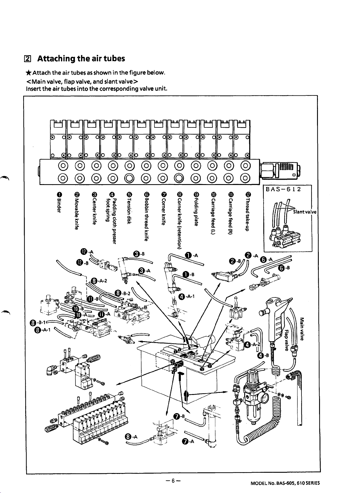
~
Attaching
the
air tubes
*Attach
<Main
Insert
the
the
valve,
air tubes
0
air
tubes
as
shown
flap
valve, and slant valve>
into
the corresponding valve unit.
in
the
figure below.
BAS-612
If''"'"''"
~
~
-6-
MODEL No. BAS-605, 610
SERIES
Page 11
c
LUBRICATION)
*Be
sure
to
use
Brother-specified machine oil (High White #70).
[lJ
Lubrication
1.
Filling
the
arm
top
oil
tank
*Pour
*Replenish
the oil from
reaches
lower line
the upper line
the
oil
cap
0 until
of
the oil gauge
the oil when the oil level
of
the oil gauge
window@.
the
oil level
window@.
is
under
the
2.
Adjusting
*Be
sure
hook
in
the
the
rotary
to
adjust
is
replaced. (The proper oil absorption scattered from
figure above.)
the
hook
oil amount
lubrication
of
the rotary hook by turning the oil adjusting screw @)after the rotary
*
Remove
Remove
the
rotary hook
the
front
cover.
the oil collected
Oil
_\
·\
White paper
for
ten
seconds
in
the
poly oiler
is
as
0.
shown
-7-
MODEL No.
BAS-605,
610
SERIES
Page 12
~
Oiling
The
oiling
Apply a few
first
time
or
places on
drops
is
not
used
the
BAS-605 and 606 are
of
oil
at
each place indicated by
for
extended period.
the
same
the
as
those on
arrows
the
when
BAS-61
the
0.
sewing machine
is
operated
for
the
-8-
m
MODEL No.
BAS
-605, 610
SERIES
Page 13
c
OPERATION)
III
Marking light
1.
Adjusting the focus
*The
*Loosen
marking
switch
hood @
material; this [ tit] mark should be sharply
focused.
By loosening the
focused [
sewing start and the other
0
*
The
sewing start
twobolts0.
light
will
come on when the power
is
turned on.
the screw
to
focus the [
tit
1 marks properly
left-right position
@,
and
bolt
e I adjust the positions
can
be adjusted by loosening
raise
or lower
tit
1 mark projected on
so
that
one
is
at
the sewing end.
of
the [ tit] mark
the
is
of
at
at
lens
the
the
the
the
the
2.
Adjusting the marking
*Loosen
Ex.
If
the
the
bolt 9 to
1:
When sewing start and end are determined
seam
is
140 mm and
light
position
adjust
the
position
the
bodice marks are set 5
Sewiogeod
of
the marking
light
as
mm
in from both ends
~
desired.
L 5
centerofthecarriagefer,'-J,.t:r:----------...:::;jr-'
5mm 130mm
5
l5
140mm
*If
the
center
*If
marking lights are positioned
of
the
[tit 1 marks, a
the
seam
length changes, loosen
welt
as
in
the
140 mm long
the
bolt 9 to
figure on the
will
be formed
adjust the marking
left
and the bodice marks are aligned
at
the desired positions.
light
positions.
with
the
-9-
MODEL No. BAS-605, 610
SERIES
Page 14
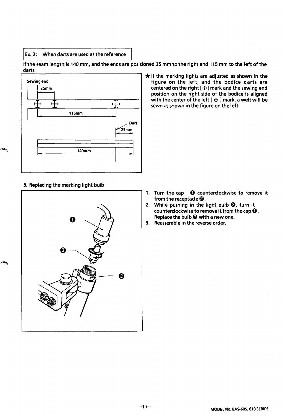
I
Ex.
2:
If
the
darts
Sewing end
3.
Replacing
When darts are
seam
length
~
25mm
r·
·1
!
..
the
marking
used
as
the reference
is
140
mm, and the ends are positioned
115mm
~mm
140mm
light
bulb
Dart
25
mm
to
the right and
*If
the marking lights are adjusted
figure
centered on the right [
position on
with
sewn
1.
2.
3.
on
the
left,
and
the
right
side
the center
as
shown in the figure on the left.
Turn the
from the receptacle
While pushing in the
counterclockwise
Replace
Reassemble
of
the
cap
0 counterclockwise
to
the bulb@)
in the
left
@.
remove
with
reverse
+]
115
mm
the
bodice
mark
and
of
the bodice
[ + ] mark, a
light
bulb
it
from
a new one.
order.
to
the
left
of
as
shown in the
darts
the sewing end
is
aligned
welt
will
to
remove
@J,
turn
it
the
cap
0.
the
are
be
it
-10-
MODEL
No.
BAS-605,
610
SERIES
Page 15
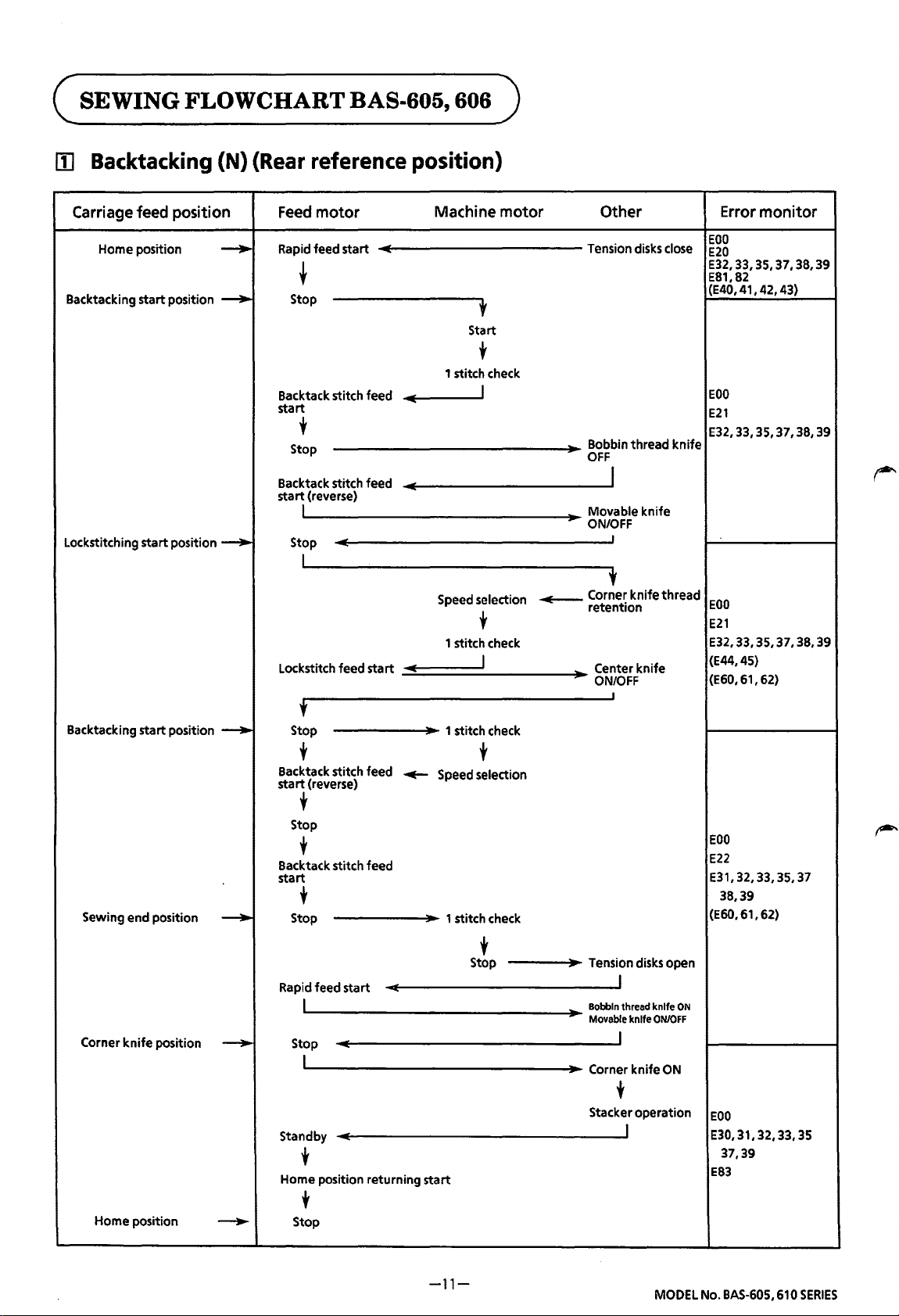
c
SEWING
FLOWCHART
BAS-605, 606 )
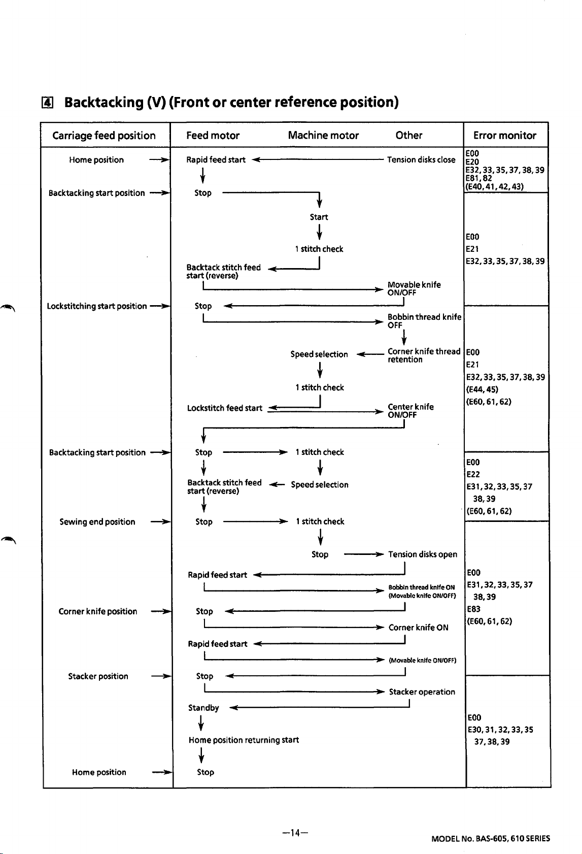
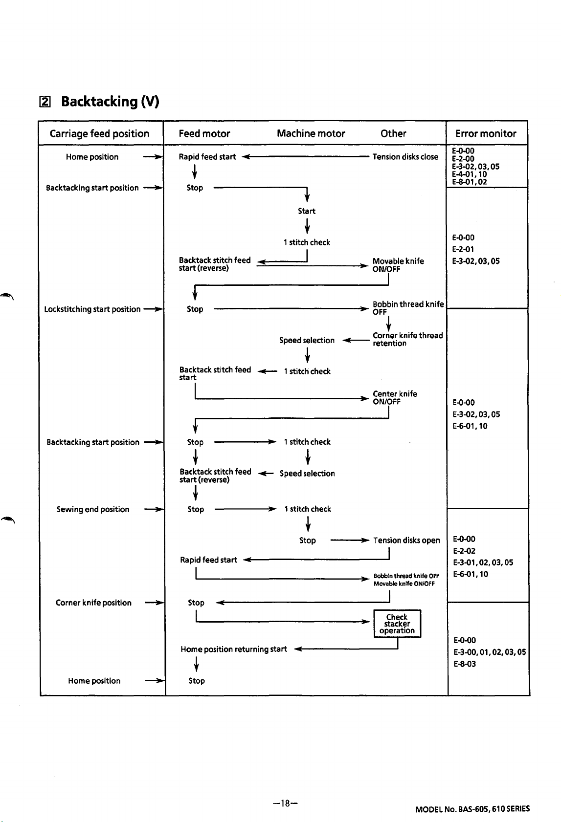
IIl Backtacking (N) (Rear reference position)
Carriage feed position
Home
position
Backtacking
Lockstitching
start
start
position
position
---..
---..
---..
Feed
motor
Rapid feed
start
t
Stop
Backtack stitch
start
•
Stop
Backtack stitch feed
startl (reverse)
Stop
I
Lockstitch
feed
feed
start
Machine
1 stitch check
IIIIi
Speed selection
1 stitch check
IIIIi
t
Start
t
I
t
I
motor
..,___
Other Error
Tension disks close
Bobbin
thread
OFF
EOO
E20
E32,33,35,37,38,39
E81,82
(E40,
EOO
E21
E32,33,35,37,38,39
knife
I
Movable
ON/OFF
Cor!er
retention
Center
ON/OFF
knife
knife
knife
thread
EOO
E21
E32,33,35,37,38,39
(E44,45)
(E60, 61, 62)
monitor
41, 42, 43)
Backtacking
Sewing
Corner
knife
start
end
position
position
position
---..
---..
~
t
Stop
Backtack stitch
•
start
(reverse)
t
Stop
Backtack stitch
•
start
t
Stop
Rapid feed
start
I
Stop
I
Standby
t
Home
position
feed
~
feed
returning
1 stitch check
t
Speed selection
1 stitch check
t
Stop
start
Tension disks open
I
Bobbin
thread knife
Movable knife
ON
ON/OFF
I
Corner
knife
ON
•
Stacker
operation
I
EOO
E22
E31,32,33,35,37
38,39
(E60, 61, 62)
EOO
E30,31,32,33,35
37,39
E83
Home
position
---..
•
Stop
-11-
MODEL No. BAS-605, 610
SERIES
Page 16
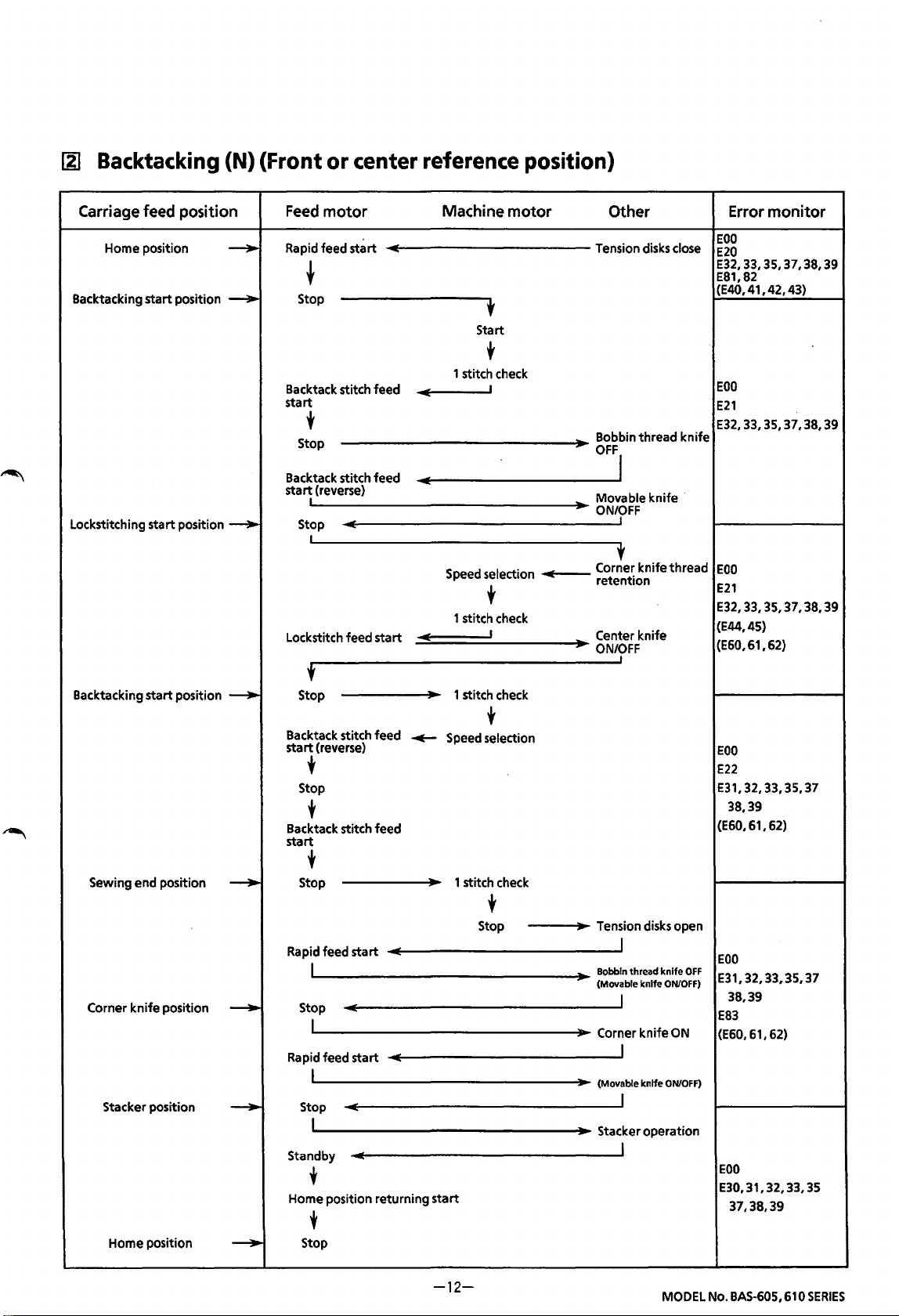
IZI
Backtacking (N) (Front
or
center reference position)
Carriage feed position
Home position
start
start
position
position--..
Backtacking
Lockstitching
--..
__.
Feed
motor
Rapid feed
sti~rt
t
Stop
Backtack stitch feed
start
t
Stop
Backtack stitch feed
sta~
(reverse)
Stop
I
Lockstitch feed
start
Machine
1 stitch check
.,
Speed selection
1 stitch check
...,
t
Start
t
I
t
I
motor
IIIIi
Other Error
Tension disks close
Bobbin
thread
OFF'
Movable
ON/OFF
Cor!er
retention
Center knife
ON/OFF
knife
knife
thread
EOO
E20
E32,33,35,37,38,39
E81,82
(E40,41,42,43)
EOO
E21
E32,33,35,37,38,39
knife
EOO
E21
E32,33,35,37,38,39
(E44,45)
(E60,61,62)
monitor
Backtacking
Sewing end position
Corner
start
knife
position
Stacker position
Home position
position
---+-
----..
____..,
----..
----..
t
Stop
Backtack stitch feed
start
(reverse)
~
t
Stop
t
Backtack stitch feed
start
t
Stop
Rapid feed
start
I
Stop
I
Rapid feed
start
I
Stop
I
Standby
t
Home position returning
t
Stop
1 stitch check
t
Speed selection
1 stitch check
t
Stop Tension disks open
Bobbin
(Movable
Corner
(Movable
Stacker operation
start
I
thread
I
I
I
I
knife
knife
knife
knife
ON/OFF)
ON
ON/OFF)
EOO
E22
E31,
38,39
(E60,61,62)
EOO
OFF
E31,32,33,35,37
38,39
E83
(E60, 61,
EOO
E30, 31, 32,
37,38,39
32, 33,
62)
35,37
33,35
-12-
MODEL No. BAS-605, 610
SERIES
Page 17
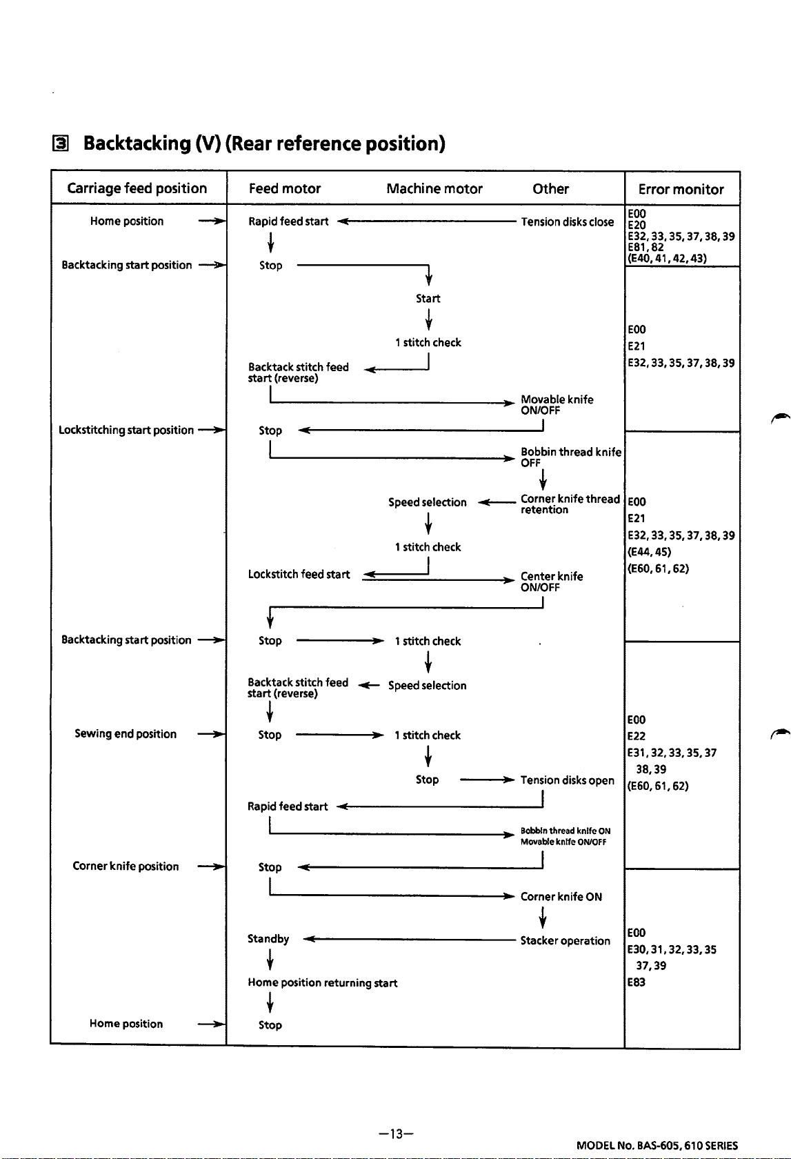
~
Backtacking
(V)
(Rear
reference position)
Carriage feed position
Home position
Backtacking
Lockstitching
start
start
position
position
--+-
_..,.
--+-
Feed
motor
Rapid feed
start
Machine
motor
Other
Tension disks close
t
Stop
t
Start
t
1 stitch check
Backtack stitch feed
stal
(reverse)
Stop
Ollf
I Bobbin thread
I
Movable
ON/OFF
_I
OFF
t
Speed selection
~
Corner
retention
t
1 stitch check
Lockstitch feed
start
Ill!
I
Center
ON/OFF
J
knife
knife
knife
knife
thread
Error
monitor
EOO
E20
E32,33,35,37,38,39
E81,
82
(E40, 41, 42,
EOO
E21
E32,33,35,37,38,39
EOO
E21
E32,33,35,37,38,39
(E44,45)
(E60,61,62)
43)
Backtacking
Sewing end position
Corner
start
knife
position
Home position
position ----+
--+-
--+
--+
Stop
'
Backtack stitch feed
start
(reverse)
t
Stop
Rapid feed
start
I
Stop
I
Standby
t
Home position returning
t
Stop
~
1 stitch check
t
Speed selection
1 stitch check
t
Stop
start
Tension disks open
J
Bobbin
thread knife
Movable knife
ON
ON/OFF
I
Corner
knife
ON
t
operation
Stacker
EOO
E22
E31,32,33,35,37
38,39
(E60,61,62)
EOO
E30,31,32,33,35
37,39
E83
-13-
MODEL No. BAS-605, 610
SERIES
Page 18
~
Backtacking
(V) (Front or center reference position)
Carriage feed position
Home
position
8acktacking
Lockstitching
start
start
position
position
--...
--..
--..
Feed
motor
Rapid
feed
start
t
Stop
Backtack stitch
sta~
(reverse)
Stop
I
Lockstitch feed
feed
start
Machine
1 stitch check
...
Speed selection
1 stitch check
...
l
Start
t
I
t
I
motor
..---
Other Error
Tension disks close
Movable
ON/?FF
Bobbin
OFF
knife
thread
EOO
E20
E32,33,35,37,38,39
E81,82
(E40,41,42,43)
EOO
E21
E32,33,35,37,38,39
knife
t
Corner
knife
retention
Center
knife
ONfFF
thread
EOO
E21
E32,33,35,37,38,39
(E44,45)
(E60,61,62)
monitor
Backtacking
Sewing
Corner
knife
Stacker position
start
end
position
position
position
--..
__..
__..
__..
t
Stop
t
Backtack stitch feed
start
(reverse)
t
Stop
Rapid
feed
start
I
Stop
I
feed
I
I
position
start
returning
Rapid
Stop
Standby
t
Home
1 stitch check
-4--
Speed selection
1 stitch check
start
t
t
Stop Tension disks open
I
Bobbin
thread
knife
knife
ON/OFF)
knife
ON
knife
ON/OFF)
operation
ON
(Movable
I
Corner
I
(Movable
I
Stacker
I
EOO
E22
E31,
32, 33, 35, 37
38,39
. (E60, 61, 62)
EOO
E31,32,33,35,37
38,39
E83
(E60, 61,
EOO
E30,
31, 32, 33,
37,38,
62)
39
35
t
Stop
Home
position
__..
-14-
MODEL No. BAS-605, 610
SERIES
Page 19
~
Condensed
stitching
(Rear
reference position)
Carriage feed position
Home
position
Condensed
Lockstitching
Condensed
s_ti.tching
posrtron
start
s_ti.tching
positron
start
position
start
____.,
____.,
----..
____.,
Feed
motor
Rapid feed
start
t
Stop
Condensed stitch feed
start
I
Lockstitch
Condensed stitch feed
start
I
I
feed
start
Machine
2 stitch check
Oil!
)I
Speed selection
.._
Speed selection
Start
t
I
motor
Oil!
____.
IIIIi
Other Error
Tension disks close
knife
Corner
retention
thread
EOO
E20
E32,33,35,37,38,39
E81,82
(E40,41,42,43)
I
EOO
E21
E32, 33, 35,
39
Bobbin
thread
knife
OFFJ
Movable
ON/OFF
Center
Center
t
I
knife
knife
knife
ON
OFF
EOO
E32,33,35,37,38
39
(E44,45)
(E60, 61, 62)
I
monitor
37,38
Sewing
end
Corner
knife
Home position
position
position
__.,.
__.,.
__.,.
+
Stop
Rapid feed
I
Stop
I
Standby
t
Home
position
t
Stop
start
returning
2 stitch check
start
t
Stop
Tension disks
I
Bobbin
thread knife
Movable
knife
ON/OFF
I
Corner
knife
t
Stacker
operation
open
ON
ON
EOO
E22
E31,
32, 33, 35,
38,39
(E60,61,62)
EOO
E30,
31, 32, 33, 35
37,39
E83
37
-15-
MODEL No. BAS-605,610
SERIES
Page 20
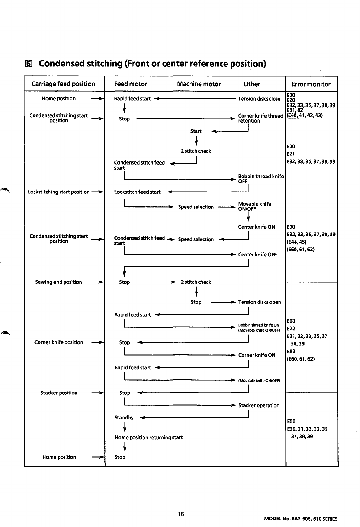
Iii
Condensed
stitching
(Front
or
center
reference
position)
Carriage feed position
Home
position
Condensed
Lockstitching start position
Condensed
stitching start
position
stitching start
position
......
_...,
---..
_...,
Feed
motor
Rapid
feed start
t
Stop
Condensed
start
Lockstitch feed start
Condensed
start
stitch feed
I
I
stitch feed
I
Machine
..,
...
_.
2 stitch
Speed
Speed
motor
Start
~
check
I
selection
selection
llf
____,.
Other
Tension
Corner
retention
Bobbin thread knife
OFF
Movable knife
ON/OFF
Center knife
II!
Center knife
disks
knife thread
I
I
~
I
I
close
ON
OFF
monitor
Error
EOO
E20
E32,33,35,37,38,39
E81,82
(E40,
41,42,43)
EOO
E21
E32,33,35,37,38,39
EOO
E32,33,35,37,38,39
(E44,45)
(E60,
61,
62)
Sewing end position
Corner
knife position
Stacker position
Home
position
......
---.
---.
......
+
Stop 2 stitch
Rapid
feed start
I
Stop
I
Rapid
feed start
I
Stop
I
Standby
t
Home
position returning start
t
Stop
check
~
Stop
Tension
disks
open
I
Bobbin
thread knife
(Movable knife
_I
Corner knife
I
(Movable knife
I
Stacker operation
I
ON
ON/OFF)
ON
ON/OFF)
EOO
E22
E31,
32, 33,
35,37
38,39
E83
(E60,
61,
62)
EOO
E30,31,32,33,35
37,38,39
-16-
MODEL
No.
BAS-605,
610
SERIES
Page 21
(SEWING
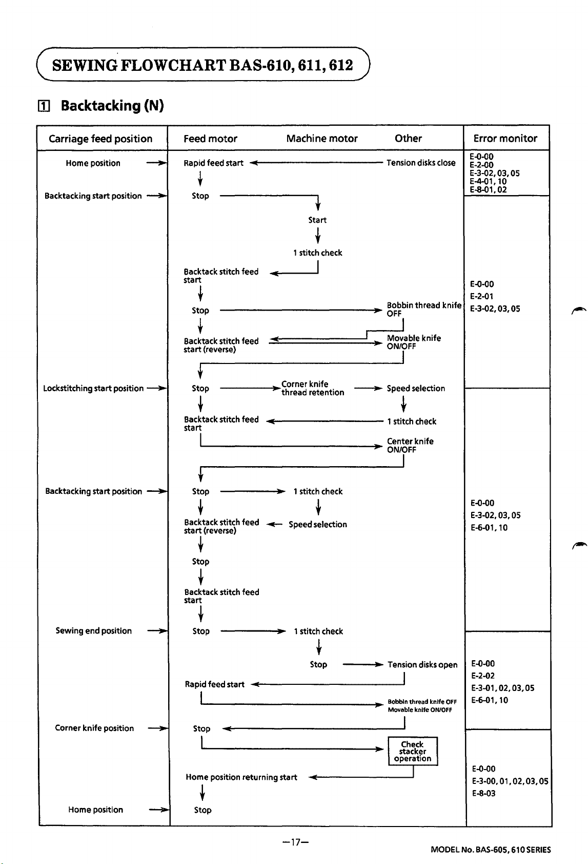
[j]
Backtacking
FLOWCHART BAS-610, 611,
(N)
612)
Carriage feed position
Home position
Backtacking
Lockstitching
start
start
position
position
--...
--...
--...
Feed
motor
Rapid feed
start
t
Stop
Backtack stitch feed
start
t
Stop
t
Backtack stitch feed
start
(reverse)
t
Stop
t
Backtack stitch feed
start
I
Machine
~
OlliE
Corner
thread
motor
t
Start
t
1 stitch check
I
knife
retention
~
Other
Tension disks close
Bobbin
,
OFF
I
I
Movable
ON/OFF
I
Speed selection
t
1 stitch check
Center
ON'IFF
thread
knife
knife
knife
Error
monitor
E-0-00
E-2-00
E-3-02, 03,
E-4-01, 10
E-8-01, 02
E-0-00
E-2-01
E-3-02, 03,
OS
OS
Backtacking start position
Sewing
end
position
Corner
knife
position
Home
position
--...
--...
--...
---..
f
Stop 1 stitch check
t
Backtack stitch
start
(reverse)
feed
~
t
Speed selection
t
Stop
t
Backtack stitch
start
feed
t
Stop
1 stitch check
t
Stop Tension disks open
Rapid feed
start
I
Stop
I
Home position
returning
start
t
Stop
I
Bobbin
thread
knife
knife
ON/OFF
Movable
J
I Check I
stacker
operation
I
E-0-00
E-3-02, 03,
E-6-01, 10
E-0-00
E-2-02
E-3-01, 02, 03,
E-6-01,10
OFF
E-0-00
E-3-00, 01, 02, 03,
E-8-03
OS
OS
OS
-17-
MODEL No. BAS-60S, 610
SERIES
Page 22
~
Backtacking
(V)
Carriage feed position
Home position
Backtacking
Lockstitching
Backtacking
start
start
start
position
position
position
--+-
--+-
--+-
~
Feed
motor
Rapid feed start Tension disks close
Machine
motor
Other Error
t
Stop
t
Start
~
1 stitch check
Backtack stitch feed
start
(reverse)
+
Stop
Backtack stitch feed
start
I
+
Stop
~
....--
I
Speed selection
~
1 stitch check
1 stitch check
...,___
Movable
ON'IFF
Bobbin
OFF
Corner knife
retention
Center knife
ON/rF
knife
thread
~
knife
thread
monitor
E-0-00
E-2-00
E-3-02, 03,
E-4-01, 10
E-8-01,02
E-0-00
E-2-01
E-3-02, 03,
E-0-00
E-3-02, 03,
E-6-01, 10
OS
OS
OS
Sewing end position
Corner
knife
position
Home position
--+-
~
--+-
~
Backtack stitch feed
start
(reverse)
......
~
Stop
Rapid feed
start
I
Stop
I
Home position returning
t
Stop
~
Speed selection
1 stitch check
~
Stop Tension disks open
Bobbin
Movable knife
~
start
I
thread knife
I
Check
stacker
operation
I
OFF
ON/OFF
_I
E-0-00
E-2-02
E-3-01, 02, 03,
E-6-01, 10
E-0-00
E-3-00, 01, 02, 03,
E-8-03
OS
OS
-18-
MODEL No. BAS-605, 610
SERIES
Page 23

~
Condensed
stitching
Carriage feed position
Home position
Condensed
Lockstitching start position
Condensed
stitching start
position retention
~i~ching
positiOn
start
~
__,.
--..
__..
Feed
motor
Rapid
feed start
~
Stop
Condensed
start
stitch feed
~
Stop
~
Lockstitch feed start
Condensed
stal
stitch feed .,._
--...
Machine
2 stitch
..,
Speed
Speed
motor
Start
~
check
I
selection
selection
..,
~
Other
Tension
Corner knife thread
Bobbin thread knife
OFF
Movable knife
ON/OFF
Center knife
..,
Center knife
disks
I
I
~
I
J
close
ON
OFF
Error
monitor
E-0-00
E-2-00
E-3-02,
03,
E-4-01,
10
E-8-01,02
E-0-00
E-2-01
E-3-02,
03,
E-0-00
E-3-02,
03,
E-6-01,
10
OS
OS
OS
Sewing end position
Corner knife position
Home position
~
__,..
~
+
Stop
Rapid
feed start
I
Stop
L
Home position returning start
t
Stop
2 stitch
Stop
check
~
Tension
I
Bobbin
thread
Movable
J
l
Check
stacker
operation
knife
I
disks
knife
ON/OFF
open
J
ON
E-0-00
E-2-02
E-3-0
1,
E-6-01,
E-0-00
E-3-00,
E-8-03
02, 03,
OS
10
01, 02, 03,
OS
-19-
MODEL
No.
BAS-60S,
610
SERIES
Page 24
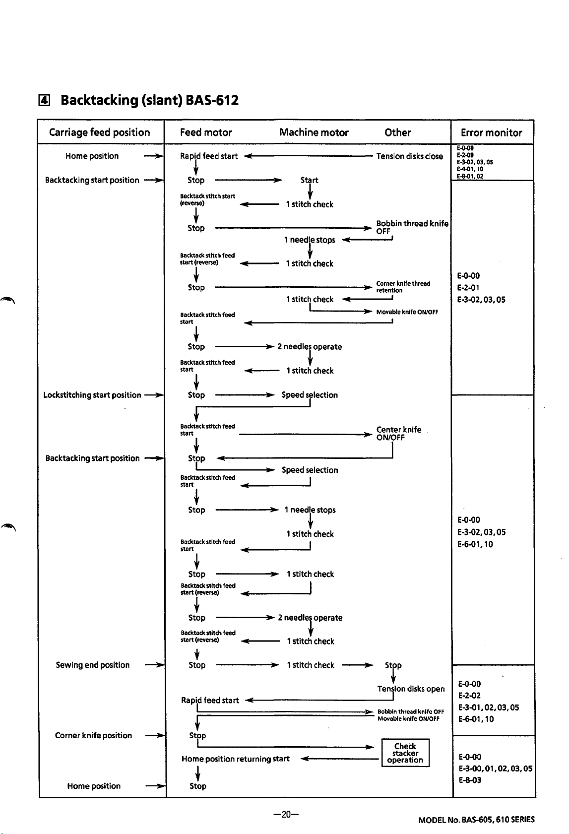
lj] Backtacking (slant)
BAS-612
Carriage feed position
Home position
Backtacking start position
Lockstitching start position
Backtacking start position
~
~
---...
---...
Feed
motor
Rap~d
feed
start
Stop Start
Backtack
stitch start
(reverse)
~
Stop
Backtack
stitch feed
start (reverse)
~
Stop
Backtack
stitch feed
start
~
Stop
Backtack
stitch feed
start
~
Stop
t
Backtack
stitch feed
start
Machine
1 stitch
1 needle
1 stitch
1 stitc,
2
needle~
1 stitch
Speed
~
strp
Becktack
start
stitch feed
Speed
motor
~
check
stops
~
check
check
operate
check
sjlection
selection
I
Other Error
Tension
disks
close
Bobbin thread knife
OFF
1
Corner knife thread
reten:lon
...
Movable knife
Center knife
ON,FF
ON/OFF
I
E-!1..00
E·2..00
E-3..02,
03,
E-4-01,10
E-8-01,02
E-0-00
E-2-01
E-3-02,
monitor
OS
03,
OS
Sewing
end
Corner
knife position
Home position
position
~
~
~
~
Stop
Backteck
stitch feed
start
~
Stop 1 stitch
Backteck
stitch feed
~
Stop
Backteck
stitch feed
(reverse)
start
Stop
.,
.,
1
1 stitch
2
needle~
1 stitch
1 stitch
'
Rapild
feed start
f
strp
Home
position returning start
~
Stop
.,
needr
I
I start (reverse)
stops
check
check
operate
check
check
)lo
Tenjion
Bobbin
Movable knife
I
Slp
disks
thread knife
Check
stacker
operation
open
OFF
ON/OFF
I
E-0-00
E-3-02,
03,
E-6-01,
10
E..()-00
E-2..()2
E-3-01,
02, 03,
E-6-01,10
E..()..()O
E-3..()0,
01,
E-8..()3
OS
OS
02, 03,
OS
-20-
MODEL
No.
BAS-605,
610
SERIES
Page 25
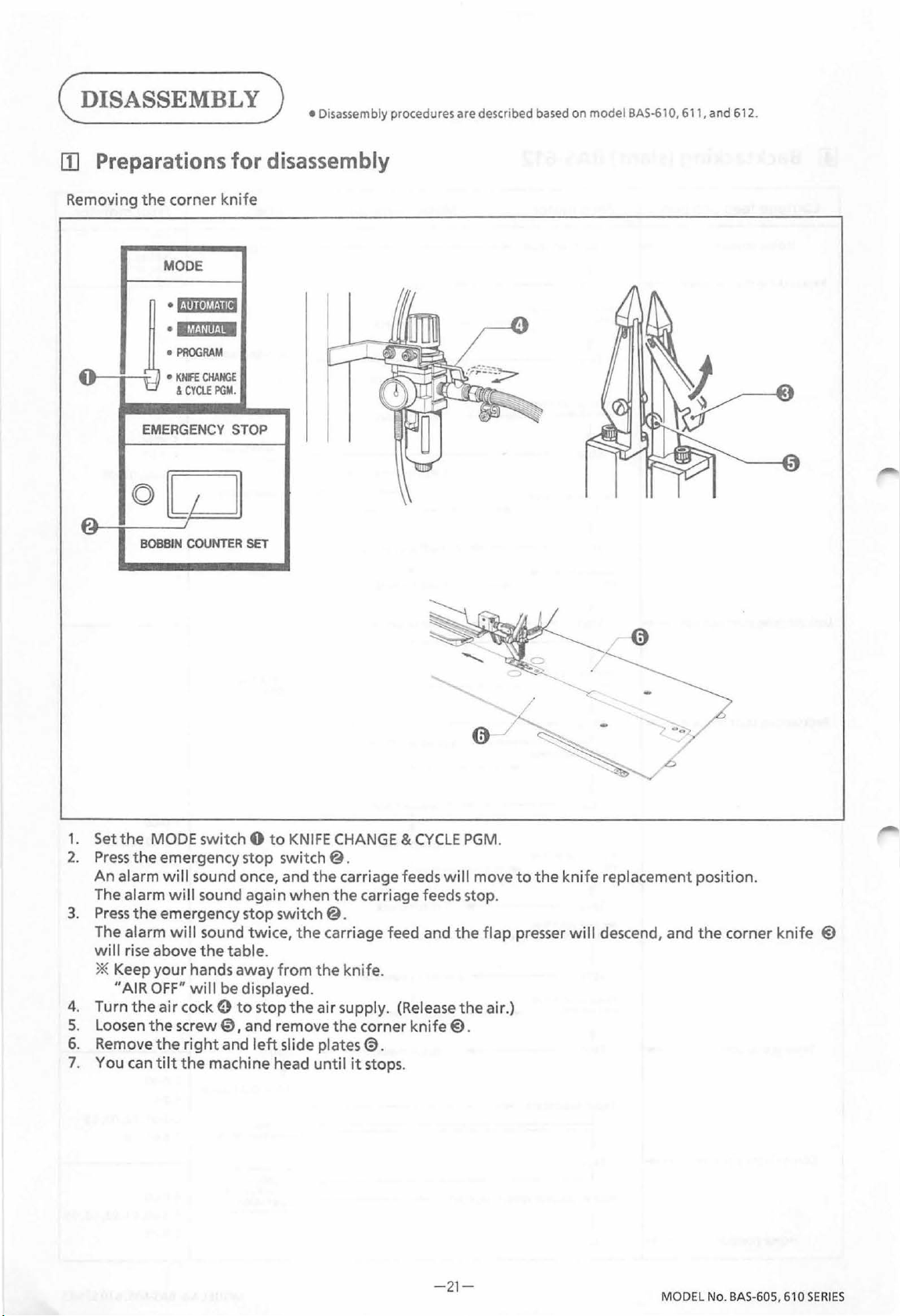
(DISASSEMBLY)
• Disassembly procedures are descnbed
based
on model
BAS-61
0, 611, and 612.
[I] Preparations for
Removing
~
'-="'
the
corner
MODE
•
·l~~~·!~ll!iJ.
•
8'
•
EMERGENCY STOP
(Q)
II
BOBBIN
knife
lil'ii·J~~·n~a
PROGRAM
KNfl:
CHANGE
&
CYClE
PGM.
I I
COUNTER
SET
disassembly
1. Set the MODE switch 0
2.
Press
the
emergency stop switch @ .
An
alarm
will
sound once, and
alarm
will
The
3.
Press
the
The alarm will sound twice,
will
rise above
sound again
emergency stop switch
the
table.
* Keep your hands away
"AIR
OFF"
will
be displayed.
4.
Turn
the
air
5. Loosen
6. Remove
7. You can
the
the
tilt
cock 0
screw
right
the
to
0,
and remove
and
machine head
to
KNIFE
the
when
the
from
the
stop
the
air supply. (Release
left
slide plates@.
until
~
CHANGE & CYCLE
carriage feeds
the
carriage feeds stop.
@.
carriage feed and
knife.
the
corner kni
it
stops.
fe@.
will
the
the
0
PGM
move
.
-'~
:<,
.
to
the knif
flap presser
air.)
0
-
. '>)
~-....../b
e replacement position.
will
descend, and the corner k
nife
@
-2
1-
MODEL No.
BAS-605,
610
SERIES
Page 26
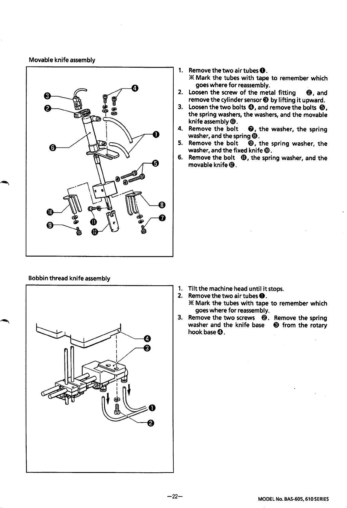
Movable knife assembly
1.
RemovethetwoairtubesO.
* Mark the tubes
goes
where
2.
loosen the screw
remove the cylinder
3.
loosen the
the spring
knife
4.
Remove
washer, and the spring
5.
Remove
washer, and the fixed knife
6.
Remove
movable knife 4i.
two
washers,
assembly
the
the
the
for
reassembly.
bolts
<9.
bolt
bolt
bolt
with
of
CD,
tape
to
remember which
the metal
sensor
e,
and remove the bolts
the washers, and the movable
&,
the
(D.
(i),
the
fitting
8 by
lifting
washer,
spring washer,
@,
it
upward.
the
spring
and
0,
the
4I!>.
the spring washer, and the
Bobbin thread knife assembly
1.
Tilt the machine
2.
Remove
the
* Mark the tubes
goes
where
3.
Remove
washer
hook
the
and
base
two
for
two
the knife
e.
head
until
air tubes
with
tape
reassembly.
screws
base
it
8.
@.
stops.
to
remember which
Remove
8 from
the spring
the
rotary
-22-
MODEL
No.
BAS-605,
610SERIES
Page 27
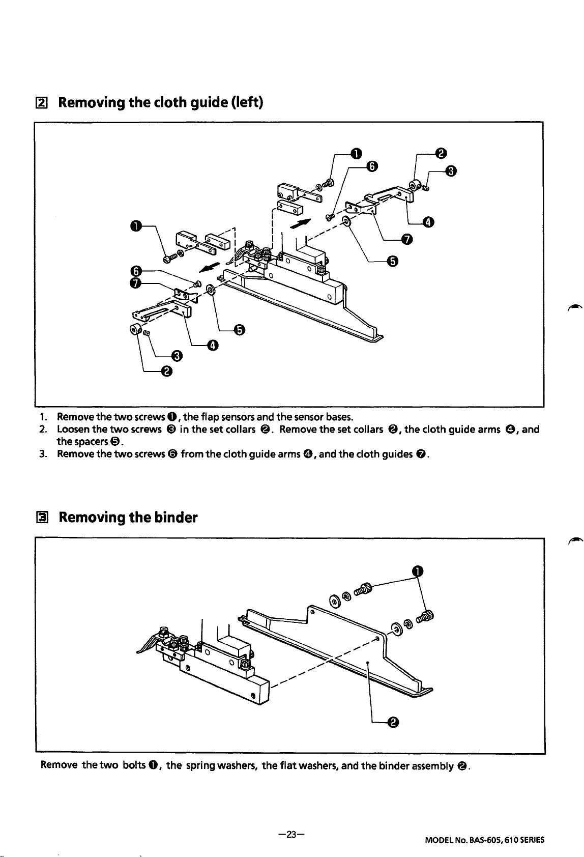
1:2]
Removing
the
cloth
guide (left}
1.
Remove
2.
Loosen
the
spacers
3.
Remove
[I
Removing
the
the
the
two
screws
two
screws
0.
two
screws
the binder
0,
@)
<9
the
flap
sensors
in
the
set collars @. Remove
from
the
cloth guide arms e, and
and
the
sensor
bases.
the
set collars
the
@,the
cloth guides & .
cloth guide arms e, and
Remove
the
two
bolts
0,
the
spring washers,
the
flat
washers, and
-23-
the
binder assembly @.
MODEL No.
BAS-605,
610
SERIES
Page 28
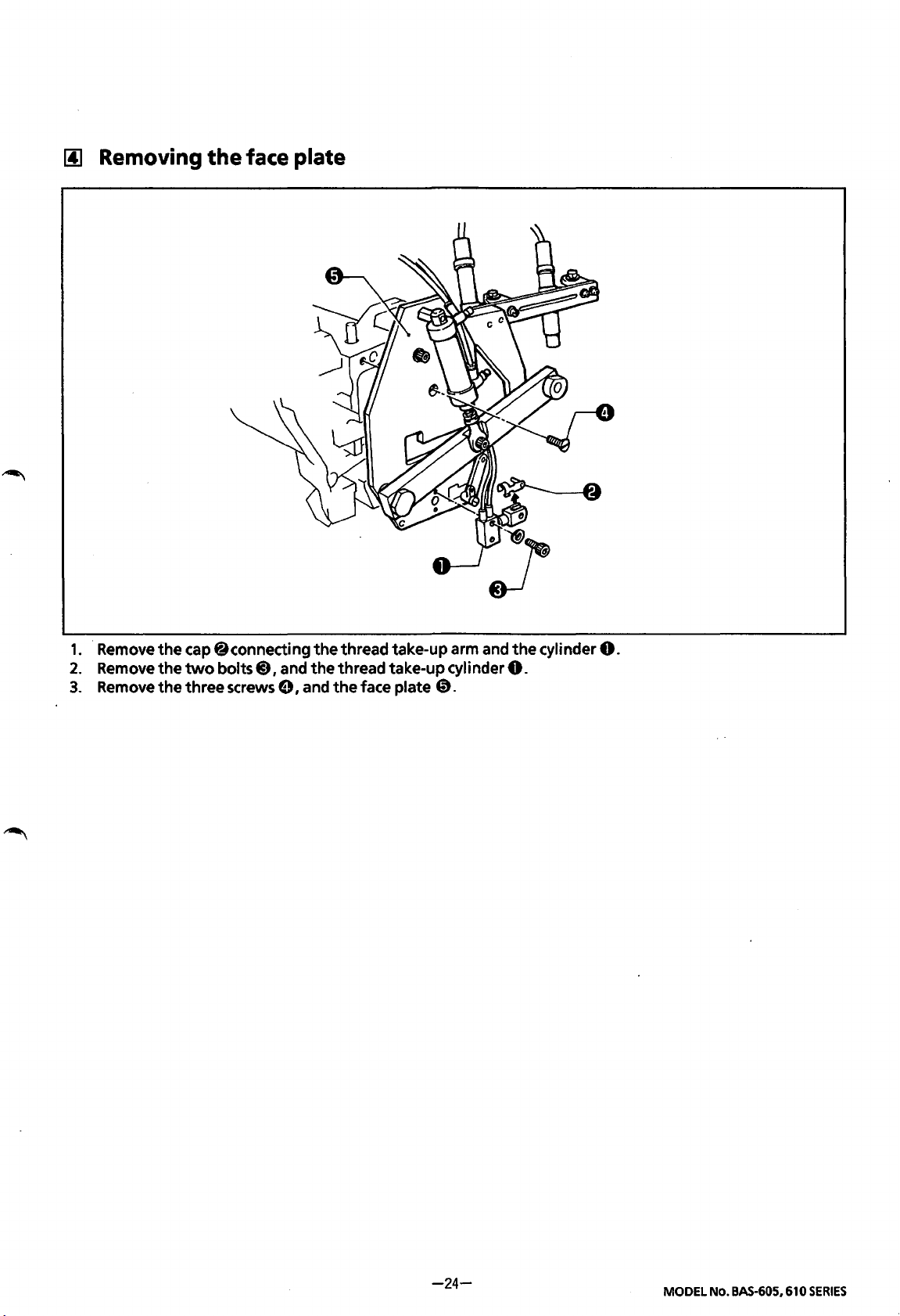
1!1
Removing
the
face plate
1.
2.
3.
Remove
Remove
Remove
the
cap @connecting
the
two
bolts@) I and
the
three screws e I and
the
thread take-up arm and
the
thread take-up cylinder
the
face plate
0.
the
0.
cylinder
0.
-24-
MODEL No. BAS-605, 610
SERIES
Page 29
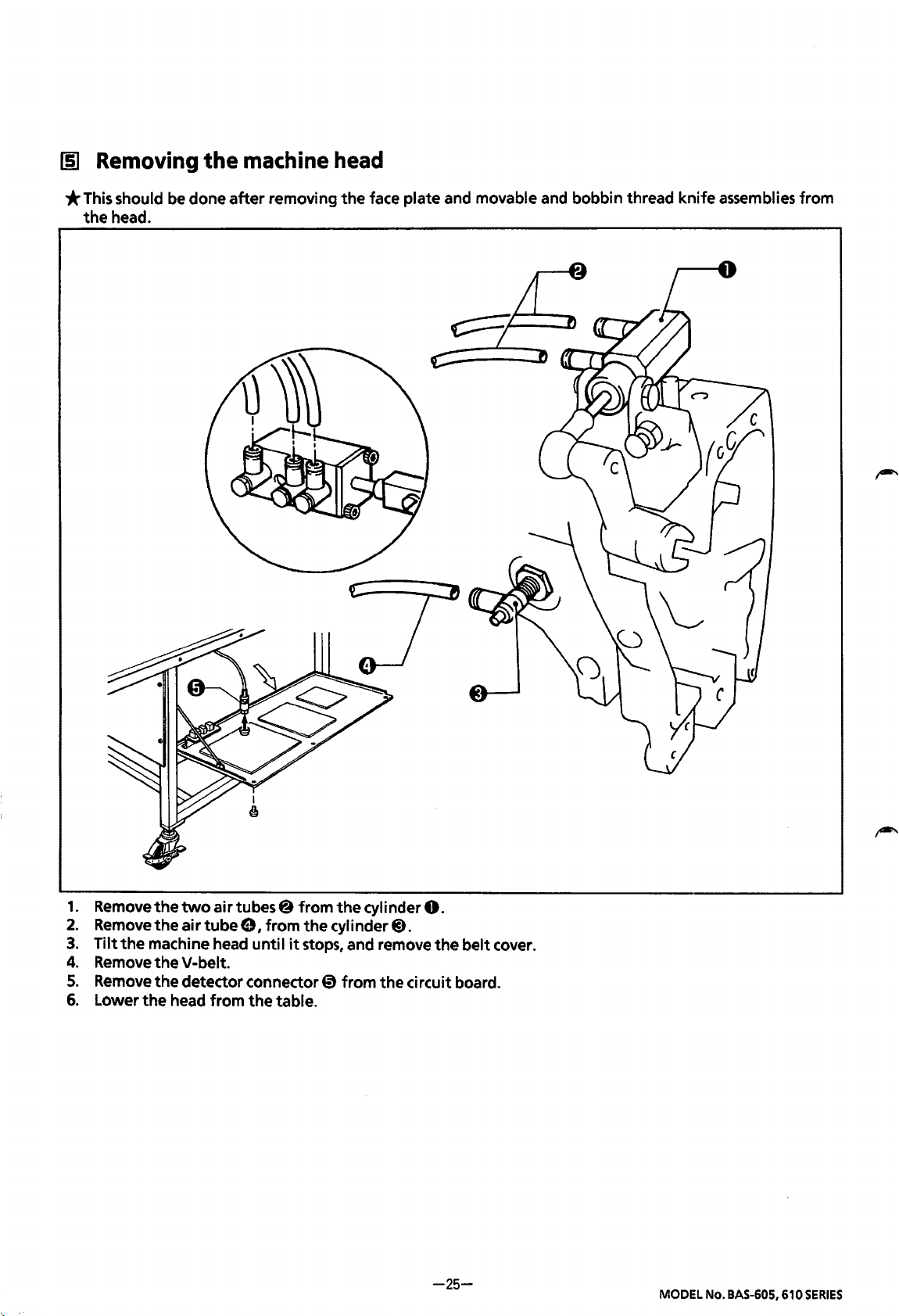
[§]
Removing
the
machine head
*This
the
should
head.
be
done
after
removing
the
face plate and movable and bobbin thread knife assemblies from
1.
2.
3.
4.
5.
6.
Remove
Remove
Tilt
Remove
Remove
Lower
the
two
air
the
air
tube
the
machine head until
the
V-belt.
the
detector connector 0 from
the
head from
tubes@ from
e I from
the
the
it
stops, and remove
table.
the
cylinder
cylinder
the
0.
8.
the
circuit board.
-25-
belt cover.
MODEL No.
BAS-605,
610
SERIES
Page 30
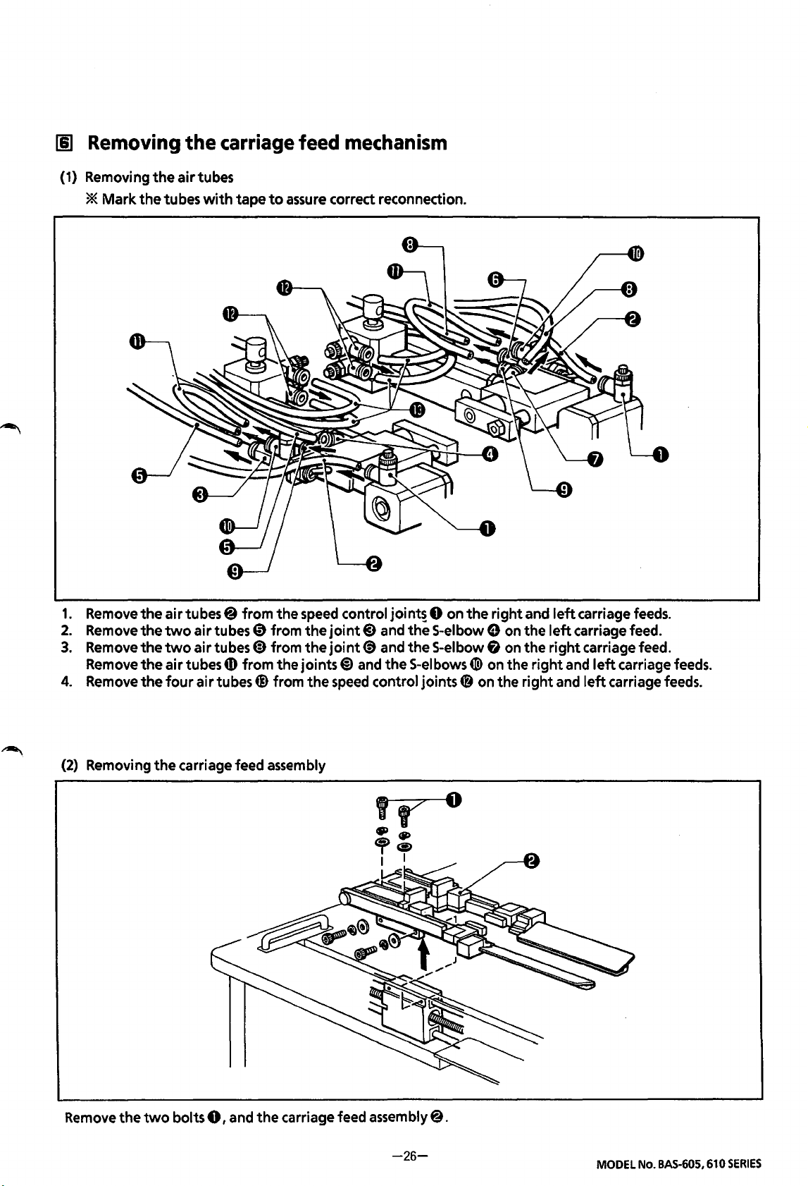
111
Removing
(1) Removingtheairtubes
*
Mark
the
the
tubes
with
carriage
tape
to
assure
feed
mechanism
correct reconnection.
1.
Remove
2.
Removethetwoairtubes@
3.
Remove
Remove
4.
Remove
(2)
Removing
the
air
tubes@ from
the
two
air
the
air tubes
the
four
air tubes@) from
the
carriage feed assembly
the
speed
from
thejoint8
tubes
(D
from
the
41)
from the joints@) and
the
control
joint(§) and
speed
joint~
and
the
control
0 on
the
the
S-elbow0
the
S-elbow8
S-elbows
joints~
4D)
on
right and
on the
on the
on the
the
right
right and
left
carriage feeds.
left
carriage feed.
right
carriage feed.
and
left
left
carriage feeds.
carriage feeds.
Remove
the
two
bolts
0,
and
the
carriage feed assembly@.
-26-
MODEL
No.
BAS-605,610
SERIES
Page 31

[1]
Removing
the feed
mechanism
(1) Removing the
(2)
Removing the corner knife cylinder assembly
DC
motor assembly
1.
Remove
assembly 0 from the circuit board.
2.
Loosen
belt0.
3.
Remove
washers,
1.
Loosen
sensor@
2.
Remove
3.
Remove
washers, and
the
two
connectors @
the
two
bolts
the
two
and the
the
screw
by sliding
the air tubes@ and
the
two
the
@,and
bolts
DC
motor assembly
0,
and remove
it
downward.
bolts
@,
corner knife cylinder assembly
@).
remove the
@,
the
0.
the
washers,
of
flat
the
0.
DC
motor
timing
and spring
the
cylinder
the
spring
(3)
Removing
the
corner knife adjusting
base
1.
Remove
2.
Remove
washers, and the corner knife adjusting
-27-
the spring
the
two
0.
bolts
@,the
MODEL
flat
No.
BAS-605,
and spring
base
@).
610
SERIES
Page 32

(4)
Removing
* Do
[I]
Removing
not
the
feed mechanism assembly
remove
or
disassemble
the
padding
the
feed mechanism unless
1.
2.
cloth
presser
absolut~ly
Remove
Remove
mechanism assembly@).
*
the
the
Be
careful
assembly@).
air
tube
four
not
necessary.
to
assembly
0.
bolts
drop
@I
and
the
feed mechanism
the
feed
(1) Removing padding cloth presser
1.
Remove
2.
Loosen
3.
Remove
(2)
Removing padding cloth presser
1.
Remove
2.
Remove
3.
Loosen
the
the
the
the
the
the
two
air
tubes
0.
two
screws@ 1 and remove padding cloth presser
two
bolts 0 I and remove
air
tube(¥).
two
screws & 1 and remove padding cloth presser
two
screws
@)I
and remove
foot
foot
I
I
I
oJ
spring
spring
(R)
the
cylinder assembly 0
(L)
the
cylinder assembly
foot
from
foot
4ID
spring
spring
from
the
the
(R)
@).
table.
(L)
@)from
table.
the
table.
-28-
MODEL No. BAS-605, 610
SERIES
Page 33

(ASSEMBLY)
[!]
Attaching the feed
(1)
Attaching
1.
Attach the feed mechanism
frame
2.
lnserttheairtube@) into the S-elbow
*The
adjusted later.
the
feed mechanism
with
the
four bolts
carriage feed
8.
position
mechanism
assembly
assembly 0 to
0.
needs
to
assembly
(2)
Attaching the corner knife adjusting
1.
the
be
Attach the corner knife adjusting
ball
the
2.
Mount the spring 0
screw
flat
*The
needs
base
base
support
and
spring
corner knife adjusting base
to
be
(R)
@)
with
washers.
on
the spring hook
adjusted later.
the
two
0
to
bolts
@,
0.
position
(3)
Attaching
the
corner knife cylinder
assembly
1.
Insert the pins @ into the channel in the corner
0.
knife lifting plate
cylinder
with
*At
assembly
flat
and
spring
this time, make
plate 0
pin
pulled
sure
original position
@.
to
that
is
not
If
it
is,
the
left
the slider
@)
pushed
the slider
Attach the corner knife
to
ball
screw
support
washers
by hand and
with
and
two
sure
the corner knife
too
far
back
~may
~
smoothly returns
the
pressure
stick when
released.
bolts
towards the
ofthe
&.
Check
that the pins @ do
the
channel in
because
2.
Connect the air tube
connect the air tube
3.
Insert the cylinder
fitting, and temporarily tighten the screw
*The
later.
they are not inserted properly.
corner knife
corner knife
41!>
to
sensor
sensor
not
come
lifting
@)
to
the
joint
the half union G).
4f}
into the metal
needs
to
be
out
plate 0
(R)
e
0.
lifting
it
is
Make
to
its
spring
of
the
@),
and
(D.
adjusted
~
(;----
---- --------
~--:J
X
-29-
MODEL
No.
BAS-605,
610
SERIES
Page 34

{4)
Attaching
the
DC
motor
assembly
0.05-0.25mm
2.5-3.Smm
1.
Attach the
2.
Insert the key 0
clearance between pulley B 0 and the motor shaft
screws~.
3.
Attach the
DC
motor
DC
assembly 0
into
the
motor assembly 0
to
the
motor bracket@
key way on the
to
support L 6 using
with
the
DC
motor shaft, and then slide pulley B @ on.
bush
to
0.05-0.25 mm, and tighten
each
two
then temporarily tighten them.
[Adjusting
4.
Mount
there
5.
Insert
the
timing
the
timing
is
2.5-3.5 mm
the
two
belt
of
belt @)on the
of
give when a
connectors
the
fD
DC
of
motor
timing
600
the
DC
assembly]
pulley
±50
g load
@and
is
applied
motor assembly
-30-
pulley B
to
0.
0.
the center
four washers and bolts@.
Set
the
the
two
set
washers, spring washers, and bolts @,
Firmly tighten
of
the
the
timing
MODEL
bolts
belt@).
No.
BAS-605,
@so
610
that
SERIES
Page 35

00
Attaching the
machine
0
head
~
I
I
I
I
1.
Set
the
head 0
* Make sure
not
more
2.
Loop
the
The V-belt @ tension should
that
sure
the
four
bolts
3.
Attach
4.
Position slide plates
that
(D)
the
the
clearances on
and fulcrum pin guides
onto
the
that
the
than
a 0.3 mm step, and
V-belt@ over
the
centers
C9,
air
tubes and
of
and slide
(R)
table
@.
bed surface
the
machine pulley e and
the
the
the
and
(L)
the
right
(R)
of
the
that
allow
15-20 mm
machine pulley e and
motor G to
detector connector.
@)
so
that
and
left
and
(L)
tD
head 0 and
the
machine head does
the
of
give when
motor
adjust
the
there
is
no clearance
sides
of
the
so
that
there
-31-
the
top
of
the
not
motor
alignment.
slide plates are equal. Adjust
is
pulley
the
belt @ is
pulley 0 are aligned.
at
the
no play either front-back
table @ are flush
wobble.
0.
pressed
front
of
the needle plate @),and
or
MODEL
or
that
there
by hand. Also make
If
they are not, loosen
the
positioning bolts
left-right.
No.
BAS-605,
610
SERIES
is
so
Page 36

jjJ
Attaching the
face
plate
1.
2.
3.
Attach
Attach
Attach
the
face plate 0
the
thread take-up cylinder@)
the
thread take-up arm and
to
the
machine head using
to
the face plate 0 using the
the
cylinder using
-32-
the
three screws@.
the
cap
0.
two
bolts
9.
MODEL No.
BAS-605,
610
SERIES
Page 37

1!1
Attaching the binder
00
Attaching the
cloth
guide
1.
Attach
plate using
bolts.
2.
Make
adjusting
slide plate.
the
binder assembly 0
the
two
the
binder and
the
height between
to
the
ruler
springs,
the
flat
washers, and
needle plate parallel by
the
binder and
fitting
the
1.
Attach
2.
Put
3.
Place
screws
up and
4.
Attach
* Refer
the
left
the
spacers
the
cloth guide arms
f)
so
that
down
the
flap
to
page 46,
and
right
e on
the
there
(down by
spacers@)
"00
cloth guides 0
fulcrum shaft@).
@)
and
is
no
play
left-right
the
spring pressure). ·
and
the
sensor
Adjusting
the
to
the
cloth guide arms
The
number
the
set collars ~ onto
in
the
cloth guide arm
bases@)
cloth guide."
using
-33-
@)
of
the
spacer 9 must match
the
fulcrum shaft
the
screws
using
@)
4ID.
two
and
screws
that
@ each.
the
gauge
@),
and tighten
the
arm moves smoothly
MODEL
No.
size.
BAS-605,
the
610
two
SERIES
Page 38

[§)
Attaching
the
movable
knife
assembly
1.
Insert the movable knife 0
with
that
of
the
knife bar@. Tighten the washer and bolt
2.
Secure
washers, and
3.
Check
and
*
4.
Attach the movable knife
Be
cylinder rod
*The
5.
Insert the cylinder
fitting
6.
Connectthetwoairtubes@
the fixed knife 0 and
bolts~
that
the knife bar @ moves both smoothly and easily, up and down. Adjust the fixed knife e
the
thread retainer spring@
lfthe
angle
of
the thread retaining spring 0
the
bolts~
sure
the
pressure should be adjusted
If
the
0)
and 8 are tightened
cylinder rod
4lD
moves easily
thread
is
to
adjust the
not
sensor
into
the
slot
of
the knife bar @, and align the hole
the
thread retainer spring @ temporarily using the washers, spring
and
8.
so
that
the thread retainer spring 0 touches the movable knife
too
much,
assembly@)
4lD
and the knife bar @ are straight and
and
cut properly, increase the
41
into
sensor.
to
using the washers, spring washers, and
does
not
strike the
to
as
little
as
the metal
the
cylinderS-elbows.
fitting
@).
is
incorrect, the thread
the
knife operation
head
when moved up and down by hand.
will
cut the thread.
pressure
slightly.
ID,
then temporarily tighten
will
of
the movable knife 0
will
not
be
properly held. Also,
become
not
too
stiff.
four
bolts@).
twisted. Also, make
the
screw
0.
sure
of
the metal
if
the
-34-
MODEL
No.
BAS-605,
610
SERIES
Page 39

[1]
Attaching
the
bobbin thread knife assembly
1.
Remove slide plates
2.
Align
the
two
bobbin thread knives @
the
insert
3.
Attach the knife
*The
knives@.
position
0.
4.
Move the cylinder rod 8
5.
6.
Connect
Return
*The
the
two
the
machine head
bobbin thread knife position needs
(R)
and
base 9 to
will
not
air
tubes@)
(L),
then
tilt
the
machine head until
of
knife holder
rotary hook
change when
left
or
right
to
the cylinder@).
to
its original position, and attach slide plates
base
the
knife
by hand
to
(R)
0 using
base 9 is
to
be adjusted later.
(L) 0 with
the
make sure
two
fitted
it
moves smoothly and easily.
it
stops.
the holes
screws@.
against
of
the
needle plate
the
step in rotary hook
(R)
and
(L).
8,
base
then
(R)
-35-
MODEL
No.
BAS-605,
610
SERIES
Page 40

[I] Attaching the
(1)
Carriage feed
carriage
feed
mechanism
~
IS\IJ>
~®
I I
I I
l
1.
Attach
washers and
2.
Make sure there
assembly and
carriage feed assembly 0
after
*After
(2)
Air
the
carriage feed assembly 0
bolts@) each.
the
the
carriage feed assembly 0
attachment, make sure
at
the
aligned
tubes
sewing end position. ·
to
the
carriage feed
is
a uniform 1 mm clearance between both the
carriage feed assembly.
right
or
is
that
If
the
left
to
adjust
removed, and
the
needle and the
clearance
the
it
fitting
is
incorrect, loosen
clearance.
is
not
usually needed.
left
and right carriage feed reference lines are
Reference
plate @ using
left
and right
the
This
adjustment
lines
the
two
flat
and spring
sides
of
the
bolts @),and shift
will
be
required only
binder
the
1.
Connect
2.
Connect
feed.
Connect
3.
Connect the air tubes@)
4.
Connect
the
the
the
the
air
tubes@
two
two
two
to
air tubes
air
tubes 0
to
air tubes
the
flap presser cylinders 0 on both carriage feeds.
@to
the
folding plate cylinders
to
the joint@) and
the
folding plate cylinder
4I!)
to
the carriage feed
the
S-elbow 9 on the
(S)
lifting
-36-
@)
and the S-elbows 9 on
and
the
cylinders
5-elbow
@).
right
carriage feed.
6.
MODEL
the
No.
left
BAS-605,
carriage
610
SERIES
Page 41

(3) Flap presser assembly
(if
not
attached)
1.
2.
3.
Remove
Lift
Attach
up
the
two
the
carriage feed
the
flap
bolts 0 and
presser assembly e
@).
the
connecting shaft supporter@.
to
the
left
carriage feed 0 using
@.
* Make sure
1 mm clearance
4.
Repeat
5.
Gently
6.
Attach
7.
Attach
*Adjust
8~
Connect
that
when
the
flap
at
the
rear
of
the
same steps
tilt
the
carriage feed.
the
connecting shaft supporter@
the
flap
stopper@)
the
flap
the
air
tube $ to
for
the
right
to
the
stopper@) according
the
cylinder assembly
presser assembly e makes contact
flap
presser
carriage feed.
carriage
to
feed@
to
the'
(L)
6.
the
carriage feed movable
using
the
washer and spring washer, and screw
flap
shape.
0.
-37-
the
with
base@)
two
spring washers and bolts
the
carriage feed
using
the
two
MODEL
No.
BAS-605,
0,
bolts
there
0.
4Ii).
610
is
a
SERIES
Page 42

00
Attaching
the
padding cloth presser
foot
spring
(1) Padding cloth presser
1.
Attach
boltsO.
2.
Attach padding cloth presser
3. Connect
(2) Padding cloth presser
1.
Set
@).
2.
Attach
3.
Attach padding cloth presser
4.
Connect
1m!
Other
1.
Make sure
tight,
2.
Turn on
3.
Set a piece
the
Check
adjust
Carriage feed".
4.
Attach
5.
Check
switch
6.
Sew and correct any improperly adjusted
the
cylinder assembly
the
two
the.top
carriage feed
end
the
cylinder@)
the
air
that
there
and
that
operation
the
air
and
of
material under
that
the
needle
the
clearance between
the
corner knives.
the
sewing operation. Next, set
to
ON, and sew.
foot
spring
@to
foot
air
tubes@
foot
of
the padding cloth pusher @)to
tube@)
is
the
to
the
to
spring (L)
to
the
table using
foot
to
the
speed control
no
excessive
is
normal.
power, and set
the
sewing end position.
is
aligned
the
(R}
the
table using
spring
the
spring
carriage feed, and operate the treadle.
with
carriage feed and the binder
(R} 9 to
cylinder speed control joints
the
two
(L)
0)
joint
play in any parts,
the
MODE
the
left
the
center knife switch
places.
the
two
washers, spring washers, washer
the
spring
55
spring washers and
to
the
table using the
fitting
mm above the
tD.
that
parts do
switch
and
Refer
to
MANUAL.
right
reference lines on the carriage feed.
to
the
sewing
shaft 8 using
f).
not
to
1 mm, referring
to
ON,
top
face
screws«!>.
two
screws@.
rub,
that
Press
and
sew.
flow
chart.
bases,
the
two
screws~.
of
the
end
of
the
all screws and bolts are
the
start switch
to
page 36, "
Then set the corner knife
cylinder
to
If
it
is
00
and
move
not,
(1}
-38-
MODEL
No.
BAS-605,
610
SERIES
Page 43

c
STANDARD
For
tilting
[]
1.
2.
3.
4.
5.
or
Adjusting
Reference line
Remove
Tilt
Align
Without
line, and remount
Return
the
the
machine head
mark A
the
ADJUSTMENT
removing
needles.
moving the upper shaft, alig n
machine head
the
on
the
machine head, refer
upper and
until
the
pulley
the
timing
to
lower
it
stops, and remove
with
the
mark on
belt
0.
its original position, and reattach
)
to
page
shaft timing
the
the
belt
the
arrow
25.
timing
cover.
mark on
belt
the
0.
lower
the
needles.
belt
@with
fG
the
arm bed referen
ce
~
Adjusting
Rotary
hook
point
1.
Loosen
clearance between
2.
Tighten
by
3.
Securely
NOTE:
the
the
turning
tighten
Tighten
Be
sure
move.
the
clearance between
Needle
0.
05
mm
or
less
screws ® , ®, © and ©
the
needle and
screws © . Adjust
the
adjust screw@.
the
screws ® , ® , and © .
the
screw ©
to
tighten
the
the
when
the
screws © securing
the
,and
shift
the
rotary hook
the
rotary hook
clearance between
lower
shaft gear@) slightly contacts
the
point
lower
needle and
base 0 to
to 1 -3
the
shaft gears
mm.
needle and
the
rotary hook
the
left
the
rotary
the
guide plate
@)
so
that
or right
hook
their
to
adjust
point
to
0.05 mm
9.
screw flats
do
the
not
-39-
MODEL No.
BAS
-605, 610
SERIES
Page 44

~
Adjusting the
clearance
between the rotary
hook
and
the
needle
plate
""'-
*The
[!]
(1) Needle bar
*The
(2)
*The
clearance between
two
screws@), and adjust
Adjusting the needle
Needle
lift
stroke
rotary hook
lowest position.
Loosen
when
Loosen
When
the
the
Needle bar height
clearance between
the
rotary
the
the
BAS-612
clearance between
point
two
screws
hook
screw@), and raise
is
the
rotary hook 0 and
the
clearance by moving
bar
should be aligned
0,
and adjust
the
upper end
point
is
aligned
or
lower
used, remove
the
upper end
the
lift
stroke
with
the
stroke by
of
the
needle hole and
with
the needle center.
the
needle bar
screw
0,
of
the
needle hole and the rotary hook
the
needle plate
the
rotary hook 0
and
the
the
needle center when
turning
and
the rotary
to
adjust
turn
the screw @
the
@should
up
needle
hook@.
rotary hook
the
height.
or
bar
the
of
be
0.6-0.9
down.
height
J*lnsertthe
needle
point
the
needle bar
point
mm. Loosen
needle bar clamp
the
way
into
the
all
is
2.4 mm above its
should be 1 - 1.5 mm
damp
to
1·-
1.5
needle bar.
to
mm.
the
adjust
~
Adjusting the
the
bobbin
clearance
case
opener
between the rotary
*The
-40-
clearance between
bobbin
bobbin
the direction
Loosen
opener @
clearance.
case
case
the bolts
hook
opener @should be
opener @
of
the
to
and
arrow.
@),
the
the
is
left
rotary hook 0 and
0.2
mm when
shifted
and shift the
or
right
MODEL
as
No.
far
as
bobbin
to
BAS-605,
the
the
possible in
case
adjust
610
the
SERIES
Page 45

[§]
Adjusting the
(1) carriage feed
<Making
1.
(Adjustment)
Loosen
Loosen
Loosen
the
needle and
Return
When moving,
the
the
the
the
bolts 0
bolts@)
bolts 0
carriage
the
carriage feed
the
carria1;1e
to
shift
to
shift carriage feed
to
shift
feed
carriage feed
to
its stop position.
feed should
carriage feed
carriage feeds
mechanism
parallel>
be
parallel
(R) @ left
(L) 9 left
(R)
or
right.
or
right.
@ and (L) e
with
left
the
or
needles
right
together.
as
shown
in
the
figure below.
<Adjusting
*The
(Adjustment)
Loosen
Set a piece
the
material slightly, check
the
carriage feed
carriage feed should contact
the
screw~
of
material under
J_-;-o---~==
0 0
and
angle>
the
material evenly.
the
stud screw 6
the
carriage feeds @ and
that
the
r-----J
qpzzaa??*&&?ZU&za&Z?&??&?&&??&&?QZ???Z&?????Qz:???
to
front
and rear parts
adjust
the
angles
9,
then
of
the
of
the
carriage feeds@ and
clamp
the
carriage feeds
material.
press
the
e.
At
this time, by pulling
material evenly.
-41-
MODEL No. BAS·605,610SERIES
Page 46

<Adjusting
*The
carriage feed
position.
the
carriage feed
front
height>
should
be
approximately
20
mm
20mm
high when
the
carriage feed
is
at
its home
~
(Adjustment)
Loosen
Loosen
*At
the
nut
the
bolt@
this time, set
head by
manually moving
---
_r-------w-----------®-1
1
0,
and adjust
to
raise the carriage feed,
the
the
height using the
power switch
the
carriage feed back and forth.
to
or
OFF,
bolt
@.
tighten the
and check
20mrj
bolt@
that
the
to
lower it.
flap
presser
does
not
strike
the
machine
-42-
MODEL
No.
BAS-605,
610
SERIES
Page 47

(2)
Folding plate
~
I
I
I
I
1.
Adjusting
The edge
the
position
of
the carriage feed 0 should be aligned
folding plate@ should be
(Adjustment)
Loosen
of
carriage feed
2.
Make
the
the
carriage feed
sure
that
two
bolts @),and shift the folding plate @
is 3-3.5
the
(Adjustment)
Bend
the folding plate@
3.
When the folding plate @
needle.
*To
check, manually pull the cylinder connecting plate 0 toward the needle, and move
0 back and forth.
feed
(Adjustment)
Release
Pull
needle.
Tighten the
secure the
*While
4.
When the gauge
carriage feed
the air.
the
cylinder connecting plate 0 toward the folding plate
Loosen
moving
the nuts 0 and @,reduce the clearance between the needle and
nut
@until the clearance between
nut
0 using a wrench, tighten the
the
is
U-SR@)
within 3-3.5
0.
Slide the folding plate @ back and
mm
in from the
mm, then tighten the bolts@).
folding plate@
so
that
is
is
fitted
on the carriage feed 0 surface.
it
lies
flat
on the carriage feed 0 surface.
protruding the furthest, there should be a clearance between
the
nut@.
cylinder connecting plate 0 toward
set
for
using
single
the
two
welt
screws
larger than
@).
with
the
edge
of
the
folding plate
front
edge
of
the carriage feed
left
or
right
so
that
its edge
forth
so
that
the distance
@by
hand. Turn
the
needle and the folding plate @
the
needle by hand, tighten the
16
mm, mount
the
folding plate supporter
@,
0.
is
aligned
to
pulley
the
folding plate @.
with
the edge
it
the
to
lower
is
1 mm. Then,
nut
0.
and
the
that
of
the
and
the
carriage
the
f)
to
-43-
MODEL No. BAS-605, 610
SERIES
Page 48

(3)
Flap presser
30mm
1.
Flap
presser angle
When
contact
a 1 mm
the
front
with
the
clearance
of
carriage feed
at
(Adjustment)
Loosen
the
flap. Then tighten
2.
Flap
The
the
flap
presser
flap
two
presser
lift
presser
bolts
0
the
stroke
0 should be approximately 30
mm above the folding plate
@ should
it
is
not
make contact
moved back and
(Adjustment)
Loosen
presser
the height or
Tighten
the
nut
0.
by either tightening
loosening
the
nut
approximately 30 mm.
the flap presser 0 makes
@,
there should be
the
rear
of
the
flap
@,
and adjust
so
that
it
presses
presser
the
the
angle
entire
0.
of
bolts@.
9.
The
carriage feed
with
other parts when
forth
by hand.
Adjust
the
0
the
the
bolt
when
height
bolt
(i
(ito
the
of
the
flap
to
increase
decrease it.
height
is
(4)
Carriage feed and flap presser operating
speed
1.
Carriage feed descent
Adjust
the
speed
assembly
carriage feed operation
2.
Carriage feed
Adjust
the
speed
assembly
carriage feed
Decrease
I
c::...L;)
i
I
Increase
-44-
decrease,
3.
Flap
Adjust
assembly
presser
loosen
or
presser descent
the
9to
operation
to
increase,
0
to
lifting
0
to
loosen
speed
the
speed
control
the
speed
occurs.
speed
control
the
speed
operation
to
increase,
speed
control
speed
at
occurs.
the
speed.
joint @ of
at
which no shock
joint
at
@of
which
occurs.
the
speed.
joint
0of
which no shock
Tighten
MODEL
No.
to
BAS-605,
the
cylinder
the
cylinder
no
shock in
Tighten
the
cylinder
in
decrease,
610
SERIES
in
to
flap
or
Page 49

Ll1
Adjusting
the
binder
Equal clearances
-Jt:
Needle
~'T~
z:;
1.
Adjusting
When
location in
(Left-
Loosen
approximately
(Front-back adjustment)
·Loosen
the
the
2.
Parallelism
The binder
and
(Adjustment)
Loosen
needle plate. Then
* Make sure
3.
Cloth slide plate height
When
cloth slide plate
*The
0.
(Adjustment)
Loosen
(standard). Then
4.
Vertical speed
The speed
ascending
(Adjustment)
1 Ascent 1
.....__
__
I Descent I Loosen (turn counterclockwise) the speed control
.....__
__
*The
the
position
the
binder
the
right
adjustment)
the
the
two
edge
of
slide plate
to
@)
seen
from
the
two
the
binder
clearance should be enough
the
nut([!)
should be adjusted
or
Loosen
_.
the
_.
increase
folding
is
lowered,
binder, and there should be a clearance from
bolt
the
the
that
descending stroke.
0,
and shift
the
center
bolts @),and shift
binder and
<9
is
carriage feed
should be parallel
the
front.
bolts
the
@)
<9
should be approximately 1 mm (standard), and these surfaces should
of
tighten
of
the
speed;
plate
of
so
1 mm. Then
8,
and shift
tighten
(turn counterclockwise)
the
timer
the
needle descends
is
lowered,
the
cylinder@), and
the
binder
tighten
speed;
can
the
needle should descend
fitting
the
needle location in
fitting
that
the
tighten
to
the
fitting
bolts
8.
the
clearance between
so
nut
4Ii).
so
that
It
should descend before
(turn clockwise)
tighten
be adjusted
r Parallel
plate A @
the
plate B 9 back and
clearance between
the
two
bolts@).
inner surface
plate C
to
the center
that
two
turn
the
binder travels
the
(turn clockwise)
to
250
@)
of
piles
the
cylinder rod until
speed control $ on
to
decrease
msec.
to
approximately
the
needle
left
or
right
binder. Then
the
of
the
carriage feed when
left
or
the
binder needle location.
the
bottom
of
the
material
as
fast
the
the
to
decrease
or
350
tighten
forth
so
bottom
right
so
of
the
as
possible
folding plate starts
the
speed.
tD
on
the
msec.
using
the
center
to
the
slot
of
so
that
the
the
bolt
that
the
needle does
of
the
binder
the
that
the binder
the
binder
will
move easily under
clearance
top
the
bottom
speed.
DIP
without
of
the
switch
is
to
cylinder
of
of
the
needle
the
binder.
needle descends
0.
not
contact
@)
and
the
top
binder
@)
approximately 1 mm
operate.
@)
is
is
parallel
and
the
top
be
parallel.
the
any shock on
@)
to
the
cylinder
2-4.
lowered
to
the
of
the
binder
the
increase
@)
to
of
to
-45-
MODEL
No.
BAS-605,
610
SERIES
Page 50

111
Adjusting
0.5-1.5
mm
1.
Left-right cloth guide position
The
clearance between
sides.
The cloth guide 0 should
The clearance
*
2.
Cloth guide
The clearance between
be
0.5-
1.5 mm (standard).
*The
(Adjustment)
Loosen
while
The clearance between
not
3.
Plate spring tension
Adjustthe
*The
(Adjustment)
Turn
4.
Cloth guide movement
There
than
the
(Adjustment)
Loosen
Adjust
than
Tighten
*For
clearance should be adjusted according 'to material thickness, and should
slide easily over
the
holding
exceed 1.5 mm. Turn
tension
may break.
the
should be no play on
5 mm
plate spring
the
the
5 mm
sewing machines
spring
the
will
height
the
nut
8 I and
the
bolt e so
tension
nut
when
two
cloth guide arm
when
the
screws@).
€)
ofthe
will
vary
If
it
is
8 clockwise
lifted
€).
screws@), and move
lifted
and
the
cloth
vary
too
cloth guide arm
guide
Spring
pressure
the
cloth guide 0 and
not
make contact
with
the
clearance between the binder and
the
bottom
cloth guide
turn
the
that
the
bottom
the
plate spring
with
material thickness;
strong,
to
increase
the
by hand, and should be descend smoothly when controlled by
@)
by hand.
with
a flap sensor, adjust
of
0.
bolt
e (tighten
it
will
of
set
screw~
€)
the
welt
the
left
and
the
so
that
there
@).
the
not
the
right
the
binder assembly @ should be equal on
with
both the needle and
the
cloth guide 0 and the
to
raise, loosen
turn, tighten the
cloth guide 0 and
to
adjust
in the cloth guide 0 according
may be pulled.
tension,
set collar
is
the
clearance.
if
the
tension
or
counterclockwise
sides
of
the cloth guide arm
4ID.
no
play on the
the
sensor
to
nut
8.
the
is
left
and
fitting
top
lower)
top
too
weak, the
right
screw
needle.
of
the
to
of
the
to
the
to
decrease
@).
sides,
so
the
binder assembly @ should
adjust
binder assembly @ should
material thickness.
that
Needle location
Equal
clearances
left
and
right
binder assembly@.
allow
the material
the
clearance. Then,
welt
may slip
the
tension.
The arm should rise more
and
so
it
does
the
that
not
or
pressure
it
rises
hit
needles
more
the
plate
to
of
-46-
MODEL
No.
BAS-605,
610
SERIES
Page 51

[I]
Adjusting the thread take-up (Required
rmJ
Adjusting the
center
knife
assembly
to
assure
1.
Make
arm and
passage.
(Adjustment)
Turn the
thread take-up
thread remainderforsewing start.)
sure
the thread take-up 0
that
it
does
not
cylinder rod
to
adjust the position
does
disrupt
the
0.
not
hit
thread's
of
the
the
(1) Adjusting the center knife
8mm
X
X
0
When
the
center knife guide 0 bottom
the center knife
guideO).
(Adjustment)
loosen the
center
* Make
two
knife@
sure
that
@
tip
and the needle plate 8
stud
screws
and
the
the center knife @ does not make contact
e, and
needle plate 8
is
raise
top
aligned
or
is
with
the
tip
top
should be 8
lower
the
center knife @
8 mm. Tighten the stud
with
-47-
of
the center knife@,
mm
screws
the fixed knife
(the
so
the
clearance between
same
height
that
the clearance between
as
the center knife
e.
0.
MODEL No.
BAS-605,
610
the
SERIES
Page 52

(2)
Adjusting
the
center
knife
stroke
Needle
---------------·
--
_J
1
1
plate
1
Stitches
_______ j _____
--------------------
_
--L
1
2
1.
The center
(Check)
Set
the
center
At
@
knife@
(Adjustment)
a. Set
b. Loosen
c.
2.
Make sure
lowest position.
(Adjustment)
Make sure
shaft.
*The
knife@
this
time,
is
at
the
knife,
that
sure
of
the
Check
If
clearance between
Center
Small gauge (8, 10, 12, 14 mm)
Large gauge (16, 18,20 mm)
knife@
power
its highest position,
should be 4 mm.
power
turn
the
the
center knife @
that
there
arm
that
that
the
it
is
not,
stroke should be approximately 6.6 mm.
and
the
air
up
and down.
make sure
the
screw 9
when
the
the
set screw
knife@
that
and
the
pulley
to
in
is a minimum
the
center
stroke
reset
is
center knife @ reaches its lowest position shortly
f)
the
ON
supply
air
the
to
the
center knife @ stroke
the
clearance between
supply
move
the
crank shaft arm
is
4 mm above
of
1 mm clearance between
knife@
6.6 mm.
in
the
eccentric wheel
set screw &
the
center
timing
OFF.
to
OFF.
center
does
in
knife@
Push
the
cylinder 0 by hand, and
is
approximately 6.6 mm. When
the
needle plate
While
pushing
knife@
the
not
the
eccentric wheel (!).
Center knife Correction
correction 0
to
@).
Change
needle plate top. Tighten
operate.
@)
and
the
1, = l2
1, = 62
the
cylinder 0 by hand
its
down
position, then stop
the
angle
the
top
is
properly positioned on
needle should
(1
increment) ·
= 5.5
= 9.4
mm-
mm-
turn
the
pulley
top
and
the
corner
to
the
of
the
upper
knife
the
screw
9.
of
the
knife holder and
after
the
needle bar reaches its
the
screw
be
5.5 mm.
approx. 0.3 mm
approx. 0.3 mm plus
to
the
center knife
of
the
operate
pulley.
At
the
rock shaft 0
this
time,
the
flat
in
the
Correction 9
8.5mm
12.5 mm
move
center
center
make
bottom
upper
the
so
-48-
MODEL No. BAS-605, 610
SERIES
Page 53

(3)
Adjusting
the
center knife pressure
1.
Adjusting
The proper position
shown in
(Adjustment)
Loosen
fixed knife @and
2.
Adjusting
Make
with
*
If
properly.
(Check
1.
After
2.
Turn the pulley while pushing
the
3.
When
turn, and should move smoothly.
(Adjustment)
Loosen
(Attach
When
smoothly and
Tighten
the
center knife
the
figure marked
the
screw @),and
the
the
center knife pressure
sure
that
the
the
center knife
the
knife pressure
for
correct knife pressure)
turning
fixed knife
the
the
the
the
the
off
8,
center knife 0
screw
CS,
center knife 0
center knife 0
the
pulley does
screw
CS.
for
center knife 0
0.
the
check
and shift
0
left-right
the
center knife 0 and
with@.
turn
the center knife holder 0
center knife
is
greater than required,
power and
that
the
crosses
the
to
the
crosses
not
X
angle
0.
Then
is
as
shown in
the
air supply, seta thread over the fixed knife
the
link
thread
with
knife bracket 8
fixed knife 8
with
become
§
tighten
ball
is
cut.
the
the
fixed knife
difficult
§
@
the
cutting edge
left
or
the
screw
@).
the
figure above when
the
knife
will
wear quickly, and
0.
When the center knife 0
fixed knife
left
0.2
mm in
to
or right.
as
@,adjust
turn.
8,
the
shown in
pulley should
of
the
fixed knife
right
to
adjust
the
fixed knife @ starts
the
figure above.)
the
center knife 0
the
the
8.
descends
not
become
@should
parallelism
knife
will
and
crosses
difficult
so
that
it
be
of
to
cross
not
with
moves
as
the
cut
to
-49-
MODEL
No.
BAS-605,
610
SERIES
Page 54

(4)
Replacing
the
center
knife
1.
Setthe
2.
Set
the
3.
Set
the
4.
Remove
* Attachment
MODE
n
•l!ll•lr111·!111
J
~
• lt!·IIIRI.
•
PROGRAM
•
KNIFE
CHANGE
&
CYa.£
PGll.
4~
MODE switch 0
CARRIAGE
power
the
switch 8
screws
is
the
FEED
9,
reverse
to
MANUAL
switch@
to
OFF.
and
the
of
CARRIAGE
FEED
to
FORWARD.
center knife
removal.
The carriage feed
0.
will
Smm
l
advance.
cautions concerning attachment
1.
Align
the
screws
2.
The
(Align
3.
Set
center knife guide
When BAS-605
1.
Set
2.
Set
3.
Remove
e.
tip
of
the
the
power
the
CARRIAGE
the
power switch@)
the
* Attachment
center knife 0
the
center knife 0 should be 8 mm above
center knife
switch
fj.
or
606
is
used
FEED
screws 0 and
is
the
tip
with
to
ON,
switch@
to
OFF.
the
reverse
with
the
screw-hole in the center knife bracket
the
center knife guide
and make sure
to
FORWARD.
center knife
of
removal.
the
that
the center knife 0
The carriage feed
0.
needle plate top.
fj
bottom.)
will
<9,
tip
does
advance.
and
secure
not
protrude from
it
using
the
the
-50-
MODEL
No.
BAS-605,
610
SERIES
Page 55

(5)
Adjusting
the
center knife cylinder
When
the
center knife 0
should be on
As
well, when
block@) should be on the
(Adjustment)
off
Turn
Loosen
so
that
Tighten
the
right
of
the
center knife 0
the
power and
the
nut ~ of
the
driving connector slide block@)
the
nut
~.
the
the
When the cylinder rod
Smm
is
raised 8 mm above
forked part
left
of
air supply, and retract the cylinder rod.
cylinder
of
the
is
raised 4 mm above
the
forked
0,
and adjust
the
selector lever
partofthe
the
is
on
the
is
extended
needle plate
$with
the
selector
protrusion
left
of
the
When the cylinder
@,the
a slight clearance.
needle plate @,
Ievere
of
the
forked part
driving connector slide block
with
a slight clearance.
cylinder rod
of
the
rod
is
retracted
the
driving connector slide
fi
by changing its length
selector lever
e.
@)
(6)
Replacing
the
MODE
D •
)
~
• MMtlihiM
•
•
fixed knife
n•ll•l!l·na
PROGRAM
KNJE
CHANGE
&CYa..EPGM.
-~
1.
Set
the
MODE switch 0
2.
Set
the
CARRIAGE
3.
Set
the
power switch
4.
Remove cloth slide plates Rand
5.
Remove
6.
Remove set
the
* Attachment
FEED
to
screw e I and
screws~,
is
the
reverse
CARRIAGE
FEED
liel&yJ.Jijel
to
MANUAL
switch@
OFF.
the
and
the
of
to
FORWARD.
L@)
needle plate
fixed knife
removal.
0.
fi.
The carriage feed
will
advance.
-51-
MODEL No. BAS-605, 610
SERIES
Page 56

IHI
Adjusting the movable knife
assembly
(1) Adjusting
the
movable
knife
stroke
There should be a
plate
8 when
(Adjustment)
Loosen
clearance.
Extend
Retract
the
the
the
the
nut
rod 0
rod 0
1.5-
2.0 mm clearance from
movable knife 0
e in
the
cylinder assembly
to
decrease
to
increase
the
the
is
at
the
clearance.
clearance.
the
bottom
@),
tip
of
the movable knife 0
of
its stroke.
and extend
or
to
the
top
of
retract the cylinder rod 0
the
cloth slide
to
adjust
the
-52-
MODEL
No.
BAS-605,
610
SERIES
Page 57

(2)
Adjusting
the
movable knife sensor
MODE
•
PROGRAM
•
KNRCHANGE
&CYQ.EPGM.
MODE
•
i·iille'f,f!ili
el@hifiitiiM
•
PROGRAM
•
KHfE
CHANGE
&
CYa.E
PGII.
~ROO
)lflitNUMBER
1 2 3 4 5
@@@@@
DCOJOJ
RAMMING
THREAD
TRIMMER
I
,-
If
I
:J
l_f
S
:?-===s
DODO
E SET
[ l
SELECT
@@@
N0.1
0
N0.2 N0.3
1.
Set
the
MODE
Set
the
seam
2.
Set
the
MODE
3.
Set a piece
4.
Press
the
The carriage feed
5.
Set
the
THREAD
The movable knife 9
Use
the
6.
Slide
the
does
not
*When
already on.
switch 0
length
switch 0
of
material
start switch@.
TRIMMER
movable knife sensor@
movable knife sensor @ up
strike
the
the movable knife e
to
PROGRAM.
to
150
mm.
to
MANUAL.
in
place
will
move
to
switch 8
will
descend.
flap presser (or
so
that
the sewing start position.
to
is
the
cushion on the underside
to
UPPER.
adjustthe
or
down, and secure
folding
off,
plate).
it
will
timing
not
operate
-53-
of
when
it
if
the
thread trimmer turns
at
the
the
movable knife sensor indicator @
of
the
carriage feed
position where
MODEL
will
not
off.
the
movable knife e
No.
BAS-605,
wear.
610
SERIES
is
Page 58

(3) Replacing
the
movable
knife
MODE
]
•1·!•11·1~1·!11
rt=l
•
Mt.!flijjM
•
PROGRAM
•
KNfE
CHANGE
I
CYCLE
PGII.
CARRIAGE
4~
FEED
1.
Set
the
2.
Set
the
replacement
3.
Set
the
4.
Remove
5.
Remove
*
Attachment
* Increase
MODE switch 0
CARRIAGE
power
the
the
the
FEED
is
easier.
switch 8
screw
9,
screw@), and
is
the
reverse
pressure
to
MANUAL.
switch @
to
OFF.
and
the
the
if
the
to
FORWARD
movable knife
fixed
knife
of
removal.
knife does
0.
& .
not
cut properly.
to
move
the
carriage feed
out
of
the
way
so
that
knife
-54-
MODEL No.
BAS-605,
610
SERIES
Page 59

Iii)
Adjusting
the
bobbin
thread knife
assembly
(1) Adjusting
the
bobbin thread knife
left-right
position
X
X
When
@left
(Adjustment)
2.
the
bobbin thread knives @ are in
or
right manually. The cylinder
*If
the cylinder rod @ movement
@ are in
1.
Loosen
Move knife holder
the
*There
the
needle plate knife holes.
the
bolt
0 in knife holder
(L)
cylinder
positioned properly
and adjust
8
at
rod@
is
usually no need
the
position
the
position where
moves easily.
0 and
to
or
if
the
of
the
the
two
knife holes
rod@
is
stiff,
(L)
the
cylinder rod @
loosen
cylinder rod movement
knife holder
cylinder rod @ moves easily.
should move smoothly.
the
knives @ may
0.
left
or
the
bolt$
(R)
in knife holder
(i}
while
of
the needle plate
be
twisted because only
right. Tighten
(R)
(i}.
is
stiff, loosen
moving
the
cylinder rod
the
bolt @ at
However,
the
bolt
0,
move the cylinder rod
the
tops
of
the
the
position where
if
the
right
knife
f)
in knife holder
@.
Then tighten
knives
is
(R)
the
not
(i},
bolt
-55-
MODEL
No.
BAS-605,
610
SERIES
Page 60

(2)
Adjusting
the
bobbin thread knife height and angle
During operation
During thread retention
The bobbin thread knives 0 should be flush
groove
operate (when
(Adjustment)
Loosen
Turn
the
* Sew
of
the
bobbin thread knives 0 should align
the
cylinder
the
bolts e I and move
the
knives 0
knives 0 operate (when
to
make sure there are neither thread
left
or
rod@
the
right
the
retracts).
bobbin thread knives 0 up
so
that
the
cylinder
rod@
with
the
top
of
the
with
the
needle plate @ groove when
or
knives 0 are parallel
extends
trimming
to
the
errors
left). Then
nor
needle plate @
down
to
adjust
to
the
groove in
thread retention errors.
their
tighten
or
the
the
up
heights.
to
0.2 mm lower. The
the
knives 0
needle plate @ when
bolts
9.
-56-
MODEL No. BAS-605, 610
SERIES
Page 61

(3)
Replacing
the
MODE
D
·l·l•ll•l!!·sla
Ji
.
•
•
4~
bobbin thread knives
CARRIAGE
FEED
l!i!·llllft1.
PROGRAM
KNfE
CHAI«iE
&CYCLE
PGM.
1.
Set
the
MODE
2.
Set
the
The
carriage feed
3.
Set
the
4.
Remove
5.
Tilt
the
6.
Loosen
C9,
and
* Attachment
Cautions on attachment
1.
Make sure
not
extend above
2.
When
grooves in the bobbin thread knives
aligned
the
switch 0
CARRIAGE
power switch
slide plates
machine head until
the
two
screws
the
knife
is
the
that
the
cylinder rod
with
the
grooves in
to
FEED
switch
will
advance.
@)
to
(R)
and
@,
base
fl
.
reverse
bobbin thread knives
the
needle plate top.
MANUAL.
OFF.
it
and remove
is
@to
(L)
0.
stops.
of
removal.
fully
the
needle plate.
FORWARD.
the
screws
retracted,
@)
should be
@)
do
the
THREAD
TRIMMER
-57-
MODEL No. BAS-605, 610
SERIES
Page 62

Ill Adjusting
the
corner knives
(1) Adjusting
When
two
the
<Dimensional
pieces
correction value
* Change
When
the
corner knife position correction value according
the
ceramic corner knife
corner knife standard position
drawing>
Sewing start
b
b
of
serge are sewn
is
set
to
0-0,
the
after
corner knife position correction value
above dimensions should
is
used,
the
Sewing end
a
a
be
1 mm.
to
material thickness.
dimensions may change according
is
set
to
to
5-S
and center knife
the
knife position.
(2)
Adjusting
1.
Adjusting
the
corner knife front-rear position (standard)
the
corner knife position
2mm
at
the
end
of
sewing
1)
Set
the
PGM.,
MODE
raise
switch
the
corner knives
to
KNIFE
CHANGE & CYCLE
0,
and release
air.
2)
The corner knives 0 cutting position should be 1
mm in from
Value
side, and move
and
forth
3)
Loosen
adjust
so
that
the
two
the
sewing end position
a.
Loosen
to
the
the
knife
the
corner knives 0
the
bolt
@ on
the
knife
base
adjust
it,
then retighten
bolt
0 on
the
sewing start side, and
base
assembly
clearance between the back
is
as
shown
the
sewing end
assembly
the
bolt
@)
back and
2 mm, then retighten
thebolt0.
*When
because
knife
or
2 mm. There should
the
knife
of
base
assembly (either on
base assembly is replaced
gauge replacement, replace one
sewing end side), and adjust
be
no significant change in
the
sewing start
the
clearance
the cutting position.
@)
back
0 .
forth
sides
the
in
of
to
-58-
MODEL
No.
BAS-605,
610
SERIES
Page 63

2. Adjusting the corner knife position
at
the
start
of
sewing
After
performing
front-rear position
Adjust
the
(Adjustment)
the
corner knife position
sewing start position
Loosen
*Sew
the
to
confirm
nut
0,
the
adjustment
is
not
correct.
as
shown in Value
turn
the
knob@
the
above dimensions.
so
in
that
to
1.
on
the
adjust
The corner knife
~
-------------------
.........
~
will
move inward.
,,"'>-731------
------------------
The
corner knife
the
preceding page, perform this adjustment
corner knife cutting position
bon
the
preceding page.
it,
then retighten
will
move outward.
the
nut
0.
of
the
if
sewing start
the sewing start
is
1 mm in from
(3)
Adjusting
*The
(Adjustment)
Sewing end:
Sewing start:
cutting position
positions,
identical.
the
corner knife
as
shown in Values c and d on
Loosen
c),
Loosen
d), then
then
the
tighten
the
tighten
of
two
two
left-right
the
corner knives should be 1 mm
bolts
0,
the
two
bolts
@)
the
two
position (angle) (standard)
the
preceding page.
move slide guide
bolts
0.
, move slide guide
bolts
@)
.
(L) @ left
(R) 0 left
X
X
in
The
_)_
__________
-)>.----------~-.
from
both
the
sewing start and end
left
and
right
clearances should also be
or
right
to
or
right
obtain
to
obtain
the
dimensions (Value
the
dimensions (Value
<(,
-59-
MODEL
No.
BAS-605,
610
SERIES
Page 64

(4) Replacing
the
corner knives
MODE
X _)
•
l·liilaJhtjili
•
war.uuraw
•
PROGRAM
•
KHlF£
CHANGE
&
CYCLEPGM.
EMERGENCY
BOBBIN
___________
STOP
COUNTER
SET
(_+
Align the
edges.
1.
Set
the
MODE switch 0
2.
Press
the
EMERGENCY
An
alarm
will
sound once, and
The alarm
3.
Press
The alarm
@)will rise above
* Keep
4. Turn
The corner knives
5.
Loosen
*Align
6.
After
7.
Pressthe
The alarm
descend.
The carriage feed
Caution concerning
o
When
applied halfway. Do over steps 1
o
If
the
corner knife@) angle.
will
the
EMERGENCY
will
your
the
air
cock 0
the
set screw
the
edge
replacing
EMERGENCY
will
you failed
corner
knife
sound once more
sound
hands
the
sound
attachment
to
the
away
to
will
€),
of
the
knives,
twice,
will
restore
@)
to
STOP
STOP
twice,
table.
stop
be locked
and replace
corner knife@)
STOP
move
is
not
KNIFE
CHANGE & CYCLE
switch@.
the
carriage feed
when
the
switch@
the
from
the
air
turn
switch@
the
to
the
the
in
the
again.
carriage feed and
the
rising knife. The display shows "AIR OFF."
supply. (Release
at
the
the
the
air
..
carriage feed and
stop position, and
air
supply
to
7.
center
PGM.
will
move
carriage feed stops.
the
the
upper position.
corner knives@)
with
the
edge
cock 0
in
step 6,
as
to
restore
the
shown
the
the
in
to
the
flap
pressers
air.)
with
new
of
the
sliders<».
the
air
flap
pressers
alarm
will
corner knives
the
figure, loosen
knife
replacement position.
will
ones.
supply.
wi
II
sound once.
will
descend, and
rise, and
the
not
be lowered even
the
screws & , and adjust
the
corner knives
corner knives
@)
if
wi
air
II
is
the
-60-
MODEL
No.
BAS-605,
610
SERIES
Page 65

(5) Adjusting
the
corner
knife
sensor
mm
MODE
l
•1·1!11•11111
)
eMii"MM
•
PROGRAM
•
KNFE
&CYa.EPGM.
4t
CHANGE
A
q
@PROGRAMMING
NUMBER
1 2 3
©>©>©>©>©>
O[[li:]J
4
5
r;;--
1
CORNER
--------------a\
::·--
-----------
KNIFE
CENTER
KNIFE
El
t
Gaugedimension
--------Q
C"'leogth
1.
Set
the
2.
Set
the
3.
Set a piece
4. When
stops.
Make sure
low,
the
MODE switch 0
CORNER
the
corner knives
KNIFE
of
material
corner knives operate
that
the
to
switch@
in
place, and
blade
will
AUTOMATIC.
and
the
press
after
of
the
corner knife cuts
not
rise sufficiently.
CENTER
the
sewing, adjust
KNIFE
start switch
the
-61-
switch@)
e.
the
position
material
to
of
at
this time.
ON.
the
sensor 0
If
the
MODEL
to
where
sensor position
No.
the
BAS-605,
610
alarm
is
too
SERIES
Page 66

{6) Corner knife operation
l
-->
1
:
Seam
1
l2
:
l3:
:
1
4
Is
: Total feed
length
Feed
amount
Feed
amount
(13 =
11 + 12)
Feed
amount
(Is
=l1 + l2 + l4)
amount
timing
=1,-2
in respect
6
No stitching 12 Skipped
4
to
seam
<----1-----l±<----
to
sewing start position
from
feed operation start position
from
sewing end position
length
65 Total stroke
Seam
length
6
Constant
1
..
to
corner knife operating position
3
to
sewing end position
~
Small gauge
Large gauge
Small gauge
Largegaug?
I,
28-190 47-209
36-190
26
,.. ~I
>
--l
~
1---7.5
---1
j'--(4)
r<:
l.:=j
1
..
34
11.5
12
47-201
(mm)
13
(1, +
12)
237
237
*Because
the large gauges (16, 18,20 mm) are 4 mm
than
(8,10, 12,14 mm),
divided
No
Min. sewing
*Actual
28~26,36~34
the
that
into
stitch feed
(t4l
length
dimensions when
14
124
120
cutting length
of
the
small knives
the
dimensions
the
large and small gauges.
Small
124mm
Small gauge
28mm
the
Is
(1, + 12 +
361
357
of
the
large knives
(S)
gauge
material
for
14)
(L)
longer
small gauges
below
Large gauge
Large gauge
is
will
120mm
36mm
cut:
for
be
-62-
MODEL
No.
BAS-60S,
610
SERIES
Page 67

(7)
Corner knife cutting
Cutting
width
width
Cutting length
Knife
{S):
approx. 7.5
Knife {L): approx. 11.5
mm
mn'\
1.
To
increase
standard:
When
width
to
Turn over one corner knife when attaching
that
the
right side
0.8mm.
Turn over both knives
mm.
2.
To
increase
knife
(L)
Cutting
Cutting length increases from 7.5 mm
*Set
bring
This
ceramic corner knife
sharp.
the
cutting
the
material
obtain a better finish angle.
left
side
of
for
example)
the
cutting length by attaching corner
on the small gauge:
width
increases 0.8 mm.
DIP
switch
the
adjustment
3-1
corner knife 4 mm closer
width
is
thin, increase
the knife
to
increase
to
increase
to
OFF,
and
can
not
be
because
to
is
attached on
turn
performed
its cutting edge
greater
the
cutting
the
width
width
to
11.5 mm.
the
knob
to
the
than
it
(so
the
by
by 1.6
to
front.
for
the
is
K
~
Standard
One corner knife reversed
Both corner knives reversed
(L)
Using corner knife
corner knife
Using ceramic corner knife
or
(S)
Cutting
ceramic
(L)
width
according
8
6 8
6.8 8.8
7.6 9.6 11.6 13.6
6.8 8.8 10.8 12.8
7.6 9.6 11.6
10
to
gauge
12
10 12
10.8
size
14
12.8
13.6 14.8 16.8 18.8
16 18
14
14.8
15.6 17.6
16
16.8 18.8
20
18
19.6
--------
-63-
MODEL No.
BAS-605,
610
SERIES
Page 68

(8)
Replacing
the
knife
f
base
set
1.
Set
PGM.
2.
Loosen
3.
Press
The
4. Stop
*
If
contact the
the
MODE
the set screws 0
the
corner knives
the
the
switch
EMERGENCY
air. Replace
set screw
slide guide@).
to
KNIFE
half
STOP
will
be raised above
the
knife
is
loosened
CHANGE & CYCLE
a turn.
switch twice.
the
table.
base
set@.
too
much,
it
may
Setting
the
knife
for
slant
welting
Corner knife
1.
(L)
Loosen
direction
knife
sewing start position.
2.
It
mm. .
3.
As
using
stitch
l
_________
:
'),_______
base
is
possible
the
the
can
the
knife
r-7---------
screws
of
the
set by adjusting
base
set screws
be easily adjusted.
0,
move knives
arrow, and attach
to
set
the
deviation
set
for
slant
@),
_
Corner knife
the
the
(S) @ to
them
position
to
welting
distance
the
to
the
to
the
maximum 4
is
adjusted
from
the
Corner knives (Knife
Size
I
Knife
base
set
Corner knife
Corner knife
Ceramic
corner knife
LR
LL
SR
SL
L
s
base
8
S15881..()()1
set
is
optional part.)
10
S15882..001
12
S15883..()()1
14
S1588~01
S09416-001
509417..001
508322..()01
S08302..001
S14051..001
s
14050..001
-64-
s
16 18
15885..()()1
S15886-001
20
515887.001
MODEL
No.
BAS-605,
610
SERIES
Page 69

Ill Adjusting the padding
(1)
Adjusting the padding cloth
The
same
presser
height
cloth
as
presser
foot
spring
the table Also, loosen the
foot
(R)
height
*When
spring
padding cloth
raised
installation surface should
the table.
(Adjustment)
adjust the protrusion
distance between the
spring
the cylinder 8
spring
tighten the
(when the treadle
Loosen
cloth
the
fittingshaft0
(R)
0 holds the padding cloth when padding
presser
nut
foot
nut
@)
nut
so
0.
ofthe
that
spring
presser
of
is33.5 mm.
foot
spring
is
pressed
be
cylinder assembly
the cylinder rod
top
of
@,
and adjust the height
padding cloth
(R)
backward),
the
same
the cylinder and the
0
is
lowered, then
(R)
height
8,
so
that
presser
0
the
as
and
the
of
foot
is
(2)
Adjusting the padding cloth
presser
foot
spring
(L)
height
1.
When padding cloth
raised, the padding cloth pusher 8 should
mm
higher than the table.
(Adjustment)
Remove
assembly
Loosen
the cylinder rod, then tighten the
Reattach the cylinder
using the
2.
Make sure
springs
padding cloth
the cloth
carriage feed operates,
sacking cloth
3.
Make
and
position
caught on spring
the
two
e from the table.
the
nut
two
screws@).
that
(R)
and
or
will
not
can
sure
that
the
carriage feed returns
with
the material held, the material
presser
screws
0,
and
the
spring tension
(L)
is
adjusted
sacking cloth
slip easily, and
be
removed smoothly.
when sewing
(R)
or
foot
@),
adjust the protrusion
assembly
the
(L).
is
padding cloth and
has
spring
and
nut@.
so
being positioned,
so
been completed
the
0
that
that
to
(L)
cylinder
to
the table
of
the
when
when
the
0
be
two
the
the
home
is
not
is
2
of
-65-
MODEL
No.
BAS-605,
610
SERIES
Page 70

(3)
Adjusting
1.
Adjusting padding cloth presserfoot spring
The ascend and descend speed should be adjusted
during presser
(Adjustment)
Tighten
speed.
Tighten
the
2.
Adjusting padding cloth presser
The
foot
(Adjustment)
Tighten
speed.
the
padding cloth presser
foot
the
screw @
the
screw e
speed.
ascend
spring operation.
speed should be adjusted
the
screw 8
spring operation.
of
the
cylinder assembly
of
the
cylinder assembly @
foot
of
the
cylinder assembly 0
foot
spring
to
spring
be
ascend
(R) 0 ascend
@to
(L) 0 ascend
as
fast
speed
to
be
decrease
to
decrease the descend speed; loosen
as
possible
to
decrease the
and descend speed
as
fast
as
possible
the
ascend
speed
without
ascend
speed; loosen
causing any shock during presser
speed; loosen
without
causing any shock
it
to
it
to
increase
it
to
increase
the
increase
the
111
Adjusting
the
tension
release
*Make
tension disk
release operates (when
not
(Adjustment)
Loosen
assembly
sure
sewing).
the
0,
that
is
at
nut
and adjust
the
least
@
play
of
in
the
needle
0.5
mm when
the
power
the
tension release cylinder
the
position
is
turned
of
the
the
thread
tension
off
and
cylinder.
-66-
MODEL
No.
BAS-605,
61 0 SERIES
Page 71

Ill Adjusting the
(1)
Adjusting
the
stacker table position
pickup
stacker
1.
Stacker table 0 height
There are
position
Raise
2.
Stacker table 0 angle
The
stacker table
0
into
*When
stacker arm e in
stacker table
of
the
which
six
vertical adjustment positions
the
arm
to
the
the
above stacker table 0 height and angle adjustments have been completed, move
cloth stock arm
reduce
0.
the
stock number; lower
can
be adjusted
table supporter
the
direction
If
the
arm strikes
for
the
8.
the
to
one
of
seven
bar@)
is
inserted.
of
normal operation by hand
the
table, readjust
stacker
arm
angles depending upon
table
to
increase
the
angle and height.
the
to
make sure
depending upon
number.
the
the
hole in
arm does
the
installation
the
stacker table
not
strike
the
the
-67-
MODEL
No.
BAS-605,
610
SERIES
Page 72

(2)
Adjusting
the
sub
table
position
Clearances should be identical on both sides.
Align
Atleasts'
1.
Sub
table 0 left-right
Adjust
the
2.
Sub
ThesubtableO
3.
Sub table 0 front-rear position
The sub table 0 should be approximately flush
4.
Sub table 0 operating angle
There should be
*The
(Adjustment)
(
(2) To remove any play
(3) Make sure
the
sub
right
and
table 0 height
table
1)
Loosen
Move
the
bolts@.
smoothly
(If
table
the
the
the
table
table 0 so
left
will
four
sub table 0 back and
@,
that
up
position
that
sides, and there
should
at
not
and
and down.
is
least a
rise
bolts
so
the
too
heavy,
beat
most
5°
angle
if
step
8.
left-right,
that
the
conditions
the
the
clearances between
is
no
0.1
in
the
3.
above
slide
forth
clearances on
in
steps 1.-4. above are satisfied, and
sub table supporter 0 may
play on
mm higher, and
the
either
with
sub
table
0 when
is
not
adjusted correctly.
sub
table
so
that
the
the
right
the
supporter e inward, and move
front-back edge
the
sub table 0 and
side.
at
most0.3 mm
front
of
it
is
and
left
be
0.1mm-0.3mm
~·
the
table @ are identical on
lower
than
the
table
8.
raised.
of
the
sub table 0
sides
are identical. Retighten
that
the
sub table 0 moves
too
close.)
the
the
table@.
sub table
is
flush
with
the
0.
four
-68-
MODEL
No.
BAS-605,
610
SERIES
Page 73

(3) Adjusting
the
stacker clamp position 1
Make sure
(Adjustment)
1.
Loosen
the
2.
Loosen
the
3.
the
the
the
table surface,
the
edge
Loosen
the
center
chuck
four
four
of
the
two
of
holder@
bolts 8 I and adjust
then
bolts (!) in
table,
bolts
the
sub
tighten
then
8,
adjust
table
is
the
tighten
0,
positioned
the
the
four
two
pillow
the
the
setting plate
then
tighten
at
the center
stacker arm e
bolts
8.
blocks 0 I adjust
bolts(!).
@)
the
two
of
the
sub table 0 and parallel
so
that
vertically
bolts
8.
the
top
of
the
stacker arm e
so
that
the
to
it.
the
stacker arm e
so
that
chuck holder @
is
it
is
parallel
is
positioned
parallel
with
to
at
-69-
MODEL
No.
BAS-605,
610
SERIES
Page 74

(3)
Adjusting
the
stacker clamp position 2
Make sure
(Adjustment)
1.
Press
assembly@
2.
Loosen
assembly@
3.
The standard opening
(Adjustment)
1.
Loosen
2.
Tighten
be decreased.
Loosen
will
3.
When
4.
Operate
the
stacker reaches
the
check
is
the
nut
is
the
nuts @ and
the
nut @ to
the
nut
be increased.
the
position
the
chuck holder assembly@
button 0 to
flush
with
e I and adjust
flush
with
of
@}.
move
@to
move
is
adj usted1 retighten
to
the
edge
of
the
sub table.
operate
the
edge
the
edge
the
chuck holder assembly@ should be
the
the
the
chuck holder assembly @I and make sure
of
the
sub
table@).
the
length
of
the
chuck holder assembly @ towards
chuck holder assembly
so
of
the
cylinder rod
sub
table@) 1 then tighten
the
nuts@ and
that
it
closes,
@away
@}.
then
secure
so
the
35
mm.
the
from
the
that
the
nut
e •
slide guide
the
slide guide
stopper
edge
t»
using the
that
the
of
the
8.
The opening
f).
chuck holder
chuck holder
will
The opening
nut
@).
-70-
MODEL No. BAS-605,
610
SERIES
Page 75

(4)
Adjusting
the
cloth release
timing
*Adjust
(Adjustment)
Loosen
material
(5) Adjusting
the
Move
Move
the
is
the
the
position
two
placed on
limit
limit
the
of
the
limit
bolts @),move
the
stacker table
switch assembly@
switch assembly@
pickup stacker operating
.,_~....,""""'4~
---.h:llo~•
switch assembly@
the
limit
switch assembly
0,
then
tighten
to
the
top
right
to
the
bottom
speed
and
Direction A
so
that
the
material
@to
the
the
bolts@).
to
advance
left
to
the
stop cushion
Adjusting
Tighten
Loosen
Adjusting
Tighten
Loosen
*
The
material extends beyond
side.
Adjusting
Tighten
cylinder speed.
Loosen
Adjusting
Adjust
the
delay
the
the
cushion
the
screw 0
the
screw 0
the
cushion when stopping
the
screw@
the
screw@
pickup stacker
the
speed in direction A
the
screw
the
screw@)
the
speed in direction B
the
valve speed control screw 9
is
placed on
top
right
or
cloth release
cloth release
when
to
decrease
to
increase
to
decrease
to
increase
cannot
@)
clockwise
to
increase
the
stacker table
bottom
timing.
timing.
stopping
the
the
the
the
be used unless
the
table on
to
the
0.
left
so
that
toward
stop speed.
stop speed .
toward
stop speed.
stop speed.
decrease
speed.
the
as
above.
A
B
stacker
the
the
the
air
-71-
MODEL
No.
BAS-605,
610
SERIES
Page 76

Ill] Adjusting
(
1)
Stacker plate
the
bar stacker
(2)
Stacker bar stop positi
on
1. Stacker plate 0
The
height
depend ing upon
cloth base@
2.
Stacker plate 0
Loosen
stacker plate 0
drapes evenly over
retighten
the
in
two
the
height
can be adj
the
the
left-right
bolts a I adjust the position
left
bolts
usted
position
frame@.
position
or right
the
stacker plate
a.
of
so
to six
the
that
positions
bar stacker
of
the
the
material
0,
then
*Make
sure
that
table.
(Adjustment)
1.
Loosen
stacker
2.
Loos
of
* The stacker bar must
the
bar@
en
the
the
table, then
four bolts@
the
stacker bar @ stops
nut a in
is
the
20
mm
retighten
away
in
not
.<:::.:.
o--1
1 \ f
_
__
J f
20
mm away from
cylinder assembly @I adjust
from
the
frame
01
then
retighten
the
pillow
the
extend beyond
block 01 adjust
bol
ts@.
the
edge
the
of
~=
=
::.::.::.
_
T•b
'""rt"e
1
the
frame 0 I and is
the
protrusion
the
stacker
the
bar@
table.
:.::::.
-:.}::::::.-:.
of
the
nut
a.
so
that
:.~
''l'lle
below
and parallel
cylinder rod
it
is
parallel
l
so
to
that
the
to
edge
the
the
-72-
MODEL No. BAS-605, 610
SERIES
Page 77

Ill Stacker operation
Bar stacker
Pickup stacker
No
stacker
Corner
turns corner
0.35
sec.
0.4
sec.
Start switch
Binder rises
.1.
Stacker
bar
(L) ON
.1.
Corner
knife
ON
.1.
knife
sensor
is
activated,
knife
OFF
.1.
0.2
sec.
timer
.1.
Flap presser rises
.1.
Carriage feed rises
.1.
Folding
plate
OFF
.1.
Wiper
barON
.1.
Corner
knife
FREE
.1.
0.2
sec.
timer
.1.
delay;
wiper
bar
.1.
delay;
holding
bar
.1.
monitor
OFF
OFF
Binder rises
Stacker
Corner
Corner
Stacker sensor
1.0
sec.
knife
turns
corner
0.2
Flap presser rises
Carriage feed rises
Folding
Stacker swing
Corner
0.2
stacker chuck
delay; Stacker swing
Start switch
.1.
chuck
.1.
knife
.1.
sensor
knife
.1.
sec.
timer
.1.
.1.
.1.
plate
.1.
.1.
knife
.1.
sec.
timer
.1.
is
activated;
.1.
.1.
ON
ON
is
activated,
OFF
OFF
ON
FREE
OFF
monitor
turns
OFF
Corner
Binder rises
.1.
Corner
knife
.1.
knife
sensor is
turns
corner
knife
.1.
0.2
sec.
timer
.1.
Flap presser rises
.1.
Carriage feed rises
.1.
Folding plate
.1.
Corner
knife
.1.
0.2
sec.
timer
.1.
Start switch
monitor
ON
activated,
OFF
OFF
FREE
Start switch
ON
Start
switch
OFF
monitor
monitor
Operation
Regular stitching; Stacker switch
cycle sewing end
During
Regular stitching;
cycle sewing end
During
of
the
stacker
cycle sewing
cycle sewing
and
carriage
Stacker switch
Stacker switch
Stacker switch
Stacker switch
Stacker switch
Stacker switch
Stacker switch
-73-
feed
ON
OFF
ON
OFF
ON
OFF
ON
OFF
after
Stacker operates; carriage feed stops
Carriage feed stops
Carriage feed stops
Carriage feeds stop
Stacker operates; carriage feed is reset
Cloth held; carriage feed
Cloth held; carriage feed
Cloth' held; carriage feed
sewing
MODEL No.
is
reset
is
reset
is
reset
BAS-605,
610
SERIES
Page 78

Iii Adjusting the foot
switch
(BAS-610,
611,
612)
*Adjust
1.
Attach
the
2.
Secure
left
3.
Position
plate 0 breaks through
the
Fine adjustment
plateO.
When
pressed
backward
the
foot
switch
the
photocoupler actuator plate 0
oval holes on the photocoupler actuator plate
the
arm
or right.
the
photocoupler actuator plate 0
arm
so
that
the
all switches turn on when the
@)
to
the
foot
switch lever 0 using the
@)
so
that: when the
the
top
photosensor
can
be made by loosening the
Neutral
to
the
foot
switch
@):
is
released from the bottom photosensor & .
arm
@)
0.
two
is
pressed
when the
screws
When
pressed
forward
foot
switch
so
that
screws @ so
backward, the photocoupler actuator
foot
8
and
is
pressed.
the
screws
switch
moving the photocoupler actuator
that
is
pressed
8 are in
there
is
forward,
the
no play
centers
to
the
top
of
the
of
-74-
MODEL
No.
BAS-605,
61 0 SERIES
Page 79

IDI
Adjusting the flap
sensor
(BAS-611,
612)
(1) Attach the flap
Tighten the
*
Put
(Right: (!] Left: [I) )
(2)
Attach the
• Insert the flap
to
the spring
•
Secure
*
The
(3)
Adjust the flap
Loosen
sensors
flap
screws@)
the stickers
sensor
the
sensor
flap
spacer
the nuts
come
sensor
so
on
the
base@
spacer
base
e using the
base 8 so
0 and the
sensor
Q)
I
and
to
the centers
on the
sensor
that the
sensor 0 to
to
sensor 0 is
the spring
base.
distinguish
base
0 between the
screws@
that the cloth guide 6
screws@
left-right position.
adjust the flap
of
should
sensor
the windows in flap
on
0.
sensor
.
the inside
left
(L)
base @ and
rises
be
replaced
position
by
The
flap
sensors
of
the
sensor
and
right
(R).
the spring
at least 5
corresponding
turning the bolts
pressers
(R)
mm.
@)
come
to
the center
base@.
base
e I
and
to
the gauge width.
())
so
and
(L)
@).
of
the window.
temporarily attach
that
both
left
and
~
it
right
-75-
MODEL
No.
BAS-605,
610
SERIES
Page 80

Adjusting
1.
2.
3. Insert a piece
4.
5.
6.
the
flap
Set
the
MODE switch 0
Set
the
MODE
damaged.
Press
the
start switch
The carriage feed
monitoring.
Release
Make sure
8
After
The carriage feed
the
air. Move
that
to
position A (both ends
adjustment
MODE
sensor sensitivity
to
PROGRAM,
switch 0
of
At
this time, adjust
the
to
material
@.
will
move
the
flap sensor
is
finished,
will
return
MANUAL.
carriage feed
of
and set
to
prevent
to
the
the
LEOs
flap sensor slot). (Turn the screws@ and 6
press
to
the
the
sewing start position, and
sensitivity referring
9 and 0 are
the
EMERGENCY
home position.
the
seam
leng
th
to
190
rubber on the underside
the
left
to
the
following
to
position B manually, and resupply air.
not
lit
when
the
carriage feed
STOP
switch@.
mm.
of
the carriage feed
and ri
ght
flap
page.
is
to
turn
off
from
being
sensors
moved from position
the
LEOs
@will
.)
start
•I·J'II•lt*1!,iUI
.M,
'&Uiit!1M
rw•PROGRAM
•
KNFE
CHANGE
&CYClE
PGM
•
. 0
EMERGENCY
Oy
STOP
I
/
BOBBIN
CQUNTER
«1)
SET
I
,-,
-,
II
,_,
E SET
f
S
~---~
DODD
'J?•:.Ot?::tiJ:=
FLAP
SENSOR
B A
~
---------
l I
~~=~=
~
~~~~~
·
~
Flap sensor
1
8~
~~=
slot
f3~
-7
6-
MODEL No. BAS-605, 610
SERIES
Page 81

<Adjust
1.
ing the sensitivi
With
the reflection plate under
positions where
2.
Turn them clockwise
3.
Place
a piece
ty>
the
sensor,
the
flap
sensor
about
of
material on the reflection plate, and make
LEOs
turn
45· from these positions.
turn
on and
off
the
.
sensitivity adjusting knobs @ and
sure
that
the
flap
sensor
LEOs
are lit.
fi
to
the
Clean
the
lamps on
Flap sensor
the
underside
of
the
flap sensor and
the
folding
plate top.
(folding
plate)
-77-
MODEL No. BAS-605, 610
SERIES
Page 82

~
Carriage feed step operation
*This
1. Insert a piece of material.
2. Holding
3.
4. Every
5.
6.
function
operating
Set
DIP
SW
Set
DIP
SW
The carriage feed
Press
the
The carriage feed
time
On
the
wi
II
operate.
When
Press
the
The carriage feed
* During
stopped,
is
the
machine every
4-7
to
4-7
to
down
start
the
second
DIP
SW
start switch @.
the
it
bfother
ft:W'J
-----
THREAD TRIMMER
J::
UPPER
1'
LOWER
used
to
ON
to
operate
OFF
to
deactivate
the
SELECT
wi
II
move
switch@.
will
move
start switch@
to
last step,
4-7
is
set
to
will
return t o its home position .
above steps
will
return
BAS-605
S E
>=====<
D
move
the
carriage feed
time
the
start switch
the
stacker.
the
stacker.
switch, 0
to
to
is
the
OFF,
3-
5, when
to
its home position.
press
the sewing start position .
the
end position
pressed,
carriage feed,
the stacker
the
the
CORNER K./CENTER K.
as
memorized on a program
is
pressed
the
start switch@.
of
condensed stitching
carriage feed
the
flap presser, and
will
not
operate.
EMERGENCY
~-
SEAM LENGTH
J-tj~Mttf~j~Mtt
1'*1J'J::.t9 A
BOBBIN
COUNTER
t?•y
t--
SET
.
will
STOP
0)
~
'-'
V
il
move
switch @ is
tR
D
or
backtacking.
to
the
the
binder
pressed
by
next step.
will
with
each step
rise, and
the carriage feed
without
the
stacker
~Fm~.L.t
------
EMERGENCY STOP
ON
sw41
42 43
oo
OF
F
~
44
45
46
47 48
o o o o • o
- 78-
MODE
L No. BAS-605, 610
SERIES
Page 83

IZil
Error
codes
(BAS-605,
606)
*The
When
machine
will
either when turning on
The
following are description
E-139:!
Switch related
Machine related
E-2*
Carriage feed related
E3*
-
Code
E-00
E-10
E-11
E-12
E-20
E-21
E-22
E-30
E-31
E-32
E-33
E-34
E-35
E-36
E-37
E-38
E-39
E-40
E-41
E-42
E-43
E-44
E-45
E-60
E-61
E-62
E-70
E-81
E-82
E-83
<Emergency
machine motor
Emergency stop switch pressed
Start switch pressed
Pedal pressed
Pedal pressed
Machine
Needle
Needle
Feed
Feed
Feed
Waiting
Incorrect feeding
Abnormal feed stop
Overrun
Feed
Feed
Abnormal
Right
Left
Right
Left
Right
Left
Left
Rightthread
Left
Memory
Corner
Positioning rod and corner
Positioning rod and corner
motor
not
at
not
stopping
home position overrun.
overrun.
not
move
for
a feed command.
to
home position
motor
encoder defective.
data
broken.
feed
flap
sensor cannot
flap
sensor cannot
flap
sensor cannot
flap
sensor cannot
flap
sensor cannot
flap
sensor cannot
and
right
thread
breakage
write/read
knife
stop>
the
EMERGENCY
will
not
operate when characters unrelated
the
error
error
when
when
power
when
power
not
stopping machine
upper position
at
to
specified position
after
operating.
thread
breakage
breakage
function
rises
at
sewing start.
STOP
stop immediately.
turned on. ·The carriage feed
pressed.
power
error
upper
restoring error.
detect
detect
detect
detect
detect
detect
or
of
each
Contents
while
power
turned
turned
on. (Padding cloth presser
turned
on. (Carriage feed
at
sewing start.
position
when
power
front
front
front
front
rear edge.
rear edge.
defective.
knife
base make contact
knife
do
switch
will
remain in the
during sewing.
error code.
Sensor related
E-4*
Thread breakage related
E-6*
Corner knife related
E-8*
of
error codes
carriage feed moving.
on.
or
with
needle
at
upper position.
at
sewing end.
within
fixed
time.
(Feed time-up)
turned
on.
edge.
edge.
edge.
edge.
when
not
contact
when
corner knife operates.
is
pressed
The
while the carriage feed
machine
same
error
foot
binder
is
rod
is
will
now
position
to
the program appear on the
error
error
See
below.
Release
spring
lowered.)
caught.
be
as
is
raised.)
in the
when the
Release
Release
Turn pulley
position.
off
Turn
Turn
off
Turn
off
off
Turn
off
Turn
off
Turn
Turn
off
off
Turn
Move carriage feed
manually.
Replace encoder
off
Turn
off
Turn
Same
as
Same
as
Same
as
Same
as
Same
as
Same
as
Same
as
Same
as
Same
as
Replace
Turn
off
Turn
off
off
Turn
is
moving,
same
status when
EMERGENCY
LED
Reset procedure
start
switch.
yourfoot
your
power.
power.
power.
power.
power.
power.
power.
power.
power.
power.
emergency stop.
emergency stop.
emergency stop.
emergency stop.
emergency stop.
emergency stop.
emergency stop.
emergency stop.
emergency stop.
PCB
power.
power.
power.
the
from
foot
from
to
set needles
with a new
with a new
feed
forward
motor
the
STOP
display,
pedal.
pedal.
to
upper
one.
one.
and
power
is
switch was
Resetting after emergency stop
*Press
the
move
to
will
operate.
Press
the
The
carriage feed
EMERGENCY
the
thread trimming position and
EMERGENCY
will
STOP
switch again.
STOP
switch again, then
return
to
the home position, and the machine
The
machine
rise.
Both the movable knife and
press
will
trim
the start switch.
the thread, and the carriage feed
will
-79-
the
be ready
bobbin thread knives
to
start sewing.
MODEL No. BAS-605. 610
will
SERIES
Page 84

Error
codes
(BAS-61 0 series)
*The
machine
either
The
following
E-1·**
E-2·**
E-3·**
when
will
not
operate when characters unrelated
turning
on
the
are description
Switch related
Machine related
Carriage
feed related
error
~
E-0-00
E-1-00
E-1-01
E-1-02
E-2-00
E-2-01
E-2-02
E-2-03
E-2-04
E-3-00
E-3-01
E-3-02
E-3-03
E-3-04 Incorrect feeding
E-3-05
E-3-06
E-3-07
E-4-01
E-4-02
E-4-10
E-S-00
E-6-01
E-6-10
E-7-00
E-8-01
E-8-02 Positioning rod and corner
E-8-03
E-9-01
E-9-02
E-9-03 Incorrect
E-9-04
<Emergency
When
machine
turned on. The carriage feed
pressed.
Resetting
*Press
EMERGENCY
Start
Treadle pressed
Treadle pressed
Machine
Needles are
Machine does
Upon stopping, pulley
Upon stopping, pulley
Carriage
Carriage feed overruns
Feed tii'T!e-up.
Waiting
Abnormal
Carriage
Feed counter
Right
No flaps
Left
flap
Cycle program
Rightthread
Left
thread
Memory
Corner
Positioning rod and corner
Malfunctioning
Incorrect
Incorrect
STOP
switch pressed
motor
not
feed overruns
for a feed
feed stop.
feed overruns
error
flap
sensor defective.
sensor defective.
breakage
breakage
read/write
knife
rises
binder
binder
flap
feeder
stop>
the
EMERGENCY
move
knives
Press
motor
the
to
will
the
will
after
emergency stop
EMERGENCY
the
thread
operate.
EMERGENCY
The carriage feed
switch pressed
when
when
power
when
power
not
stopping machine
at
upper position
not
stop
with
has
has
to
to
command.
after
restoring error.
to
interrupted.
function
at
sewing start.
welt
piece
vertical
motion
sliding
motion
motion
STOP
stop immediately. The machine
STOP
trimming
STOP
will
return
power
error
power
passed
not
home position side
feeding direction.
home position side
knife
knife
tray
or
during
of
each error code.
E-4-*
E-6-*
error
E-8-*
Contents
turned
turned
needles
reached
(Cycle program
defective
base make contact
do
switch
will
of
while
carriage feed moving.
turned
on.
on. (Padding cloth presser
on. (Carriage feed
with
at
sewing start.
at
upper
the
correct stopping
the
not
contact
is
pressed
remain
sewing.
*
Sensor
*
Thread breakage related
*
Corner knife related
error
code
needle
at
upper position.
positions
correct stopping
after
when
is
cleared.)
sewing.
power
when
when
at
point
corner
while
in
the
same position
switch again. The machine
position and
switch again, then
to
the
home position, and
will
press
to
related
foot
or
binder
is
sewing end.
by a fixed angle.
point
by a fixed angle.
turned
on.
rod
is
caught.
knife
operates.
the
carriage feed
will
now
will
rise. Both
the
start switch.
the
the
program are shown on
error
spring
lowered.)
machine
error
error
is
raised.)
is
moving,
be in
the
same status
as
when
the
EMERGENCY
trim
the
thread, and
the
movable knife and
will
be ready
the
LED
display,
Resetting procedure
See
below.
start
Release
Release your
Release
Turn
position.
Turn
Turn
Turn
Turn
Turn
Turn
Turn
Turn
Turn
Turn
Move carriage feed
operator
Same
Same
Insert flap.
Same
Cycle
reset
Same
Same
Replace circuit board.
Turn
Turn
Turn
Adjust cylinder position.
Adjust
Adjust cylinder sensor position.
Adjust cylinder sensor position.
switch.
foot
from
treadle.
your
foot
from
treadle.
pulley
to
set needle
off
power.
off
power.
off
power.
off
power.
off
power.
off
power.
off
power.
off
power.
off
power.
off
power.
manually.
as
emergency stop.
as
emergency stop.
as
emergency stop.
program
after
as
as
off
off
off
will
it
is
cleared.
emergency stop
emergency stop
power.
power.
power.
cylinder sensor position.
the
feed
when
STOP
the
carriage feed
the
to
start sewing.
to
away
be automatically
motor
the
switch was
bobbin thread
upper
from
power
and
is
will
-80-
MODEL No. BAS-605, 610
SERIES
Page 85

Ia Initializing
the
memory
*This
1.
2.
3.
<Default
is
used
to
clear and initialize
Turn
off
the
power.
Set
DIP
SW
3-8 on
Turn on the power.
will
Memory
After
writing
bobbin thread number
Turn
off
Set
DIPSW
values
Display
Seam
Reference position
Corner knife
correction value
Center knife
correction value
Bobbin thread
counter value
Production
counter value
be cleared, and standard data
the
power.
3-8to
for
length
the
main circuit board
is
completed,
OFF.
BAS-605
36 mm
28 mm.(for
the
backup data required
the
buzzer
LEOs 1 to 3 will
,
606>
Seam
length
(for
large gauge)
small gauge)
Rear
5=5
0-0
100
0
to
ON.
will
will
all light.
for
sewing.
be
written
sound once, and program number
to
<Default
Cycle
Program
Program®
Program@
Flap correction
Flap
the
machine.
values
for
sewing
BAS-610,
<D
Program®
Program~
<D
correction ® 40.0mm
LEOs 1 to
611,
612>
1-+2-+3
28mm(36mm)
SOmm
100mm
·150mm
190mm
40.0mm
5 and
the
Flap
correction®
correction ®
Flap
correction
Flap
Corner
Corner knife correction ®
Corner knife correction ®
Corner knife correction @
Corner knife correction
knife correction
Bobbin thread
Bobbin
Bobbin
thread®
thread®
<S>
<D
<S>
<D
40.0mm
40.0mm
40.0mm
5-5
5-5
5-5
5-5
5-5
100
150
200
pes.
-81-
MODEL No. BAS-605, 610
SERIES
Page 86

Ill
*
DIP
Be
switch settings
sure
to
turn
off
the
power
(BAS-605,
before
changing
606)
the
DIP
switch setting.
Lockstitch pitch
Fraying prevention
Backtackin~
Condensed stitch
Backtackin~
length
seam
Motor
Carriage
feed
Carriage
operating
Flap presser
sequence
stitch
lengt
length
seam
con ensed SW2-2
length
speed SW2-3
feed
rapid
speed
feed
sequence
operating
SW1-1
SW1-2
SW1-3
(mm)
SW1-4 ON : Backtacking (V,
SW1-5
SWt-6
(mm)
SW1-7
SW1-8
(mm)
SW2-1
(mm)
SW2-4
SW2-5
SW2-6
~
SW2-7
OFF
OFF OFF
OFF OFF OFF
1.8
OFF
OFF
0.8 1.2 1.6
OFF
OFF
0.4 0.6
OFF
OFF OFF
3.0 4.0
ON:
ON:
Right-+Left Left-+Right
ON
2.0 2.2
ON
OFF
ON.
OFF
ON
2500spm
20m/min
OFF
OFF
ON
OFF
OFF
ON
OFF
ON
OFF
ON
0.8
OFF
ON ON
5.0
OFF
OFF : 15
:Right
flap
:Right
flap
: 2200 spm
m/min
ON
OFF
Right-+
Left-+
ON
ON
OFF
2.4
ON
ON
2.0
ON
ON
1.0
ON
6.0
Left Left
Right
OFF
OFF
ON
N)
Simultaneous
ON
OFF
ON ON ON
2.6 2.8
OFF
: Condensed
~
/-;;
6
I
ON
I
OFF
ON ON
carriage feeds
flap
Left
flap
~
SW1
2345678
L&R
Left-+
Right-+
OFF
ON ON
3.0 3.2
ON
~
<
~
SW2
SW3
ON
Simultaneous carriage feed
and flap pressers
Right
Left
I Foot switch
Gauge
Operation
breakage
Stacker
I Carriage
I Sensor
Memory
feed
adjustment
initialization
Option
operation
after
I SW2-8
thread
/
type
standby I SW3-6
I SW3-7
SW3-1
SW3-2
SW3-3
SW3-4
SW3-5
~
SW3-8
SW4-1
SW4-2 ON : Corner
SW4-3
SW4-4
SW4-5 Unused
SW4-6 ON : Center
SW4-7
SW4-8
OFF
OFF
No
monitoring
OFF
OFF
Pick-up Bar Roller
ON
: Adjusting sensor
: Initializing
ON
ON : Darts stretcher
ON : Automatic
:
Automatic
ON
ON
: Stacker used
ON:
N-shaped backtacking
memory
knife
welt
knife
ON:
sensor
flap
used
ON
8,10,12,14
Stop
ON
: Start switch
piece
feeder
: Multi-steps OFF: Timer
ON
OFF
at
corner
position
ON
OFF
feeder
mm
knife
monitor
OFF: V-shaped backtacking
OFF:
OFF
ON
Immediately stop Re-sewing
OFF
ON
16,18,20
OFF: Timer
mm
ON
ON
ON
ON
Pneumatic
-82-
MODEL No. BAS-605, 610
SERIES
Page 87

*Be
sure
to
turn
off
the
power
before changing
the
DIP
switch setting.
Lockstitch pitch
*When
I Fraying
arriage
corner
prevention
Backtacking pitch
Condensed pitch
Backtacking
Condensed
Motor
feed
knife
Carriage
operating
Flap presser
operatmg
operation
Switch
the
BAS-612
length
length
speed
speed
position
feed
sequence
sequence
SW1-1
SW1-2
SW1-3
(mm)
is
used, V backtacking
I SW1-4
SW1-5
SW1-6
(mm) 0.8
SW1-7
SW1-8
(mm)
SW2-1
SW2-2
(mm)
SW2-3
to
SW2-4
SW2-5
SW2-6
~
SW2-7
SW2-8
OFF
OFF
OFF
1.8
ON
OFF
OFF
2.0
will
OFF
OFF
OFF
OFF
0.4 0.6
OFF
OFF
3.0
ON·
Right...,.Left
ON
OFF
1.2
ON
OFF
ON
OFF
4.0 5.0
2500spm
ON:20m/mim
OFF: 15 m/mim
OFF
OFF
ON
OFF
OFF
ON
OFF
2.2
start even
ON •
OFF
ON
1.6
OFF
ON
0.8
OFF
ON ON
OFF
· 2200 spm
Left~Right
:Right
flap
:Right
flap
ON:
ON
ON
OFF
2.4
if
DIP
SW1-4
Backtacking
ON
ON
2.0
ON
ON
1.0
ON
6.0
ON
OFF
Right~Left
Left..,. Right
FOOT
OFF
OFF
ON
2.6 2.8
is
set.
OFF
· Condensed
ON
OFF
ON
~
~
~~~
ON
2345678
I
OFF
ON ON
Simultaneous
Left
flap
Left
flap
OFF: T1merstart
OFF
SW1
Simultaneous
Left...,.Right
Right...,.Left
ON
ON
3.0
A
SW2
and
SW3
ON
flap
ON
ON
ON
3.2
carriage
presser
feed
*When
Operation
breakage
Stacker
I Cam
age
Check
the
BAS-612
~auge
after
thread
type
feed
Option
..
positiOn I SW3-6
routine
is
used, set DIPSW3-1
SW3-1
SW3-2
SW3-3
~
SW3-4
SW3-5
-----
SW3-7
SW3-8
SW4-1
SW4-2
SW4-3
SW4-4
SW4-5
SW4-6
SW4-7
SW4-8
to
OFF.
BAS-610 •
ON:
8,
10,12,14
OFF:
16,18,20
OFF
OFF OFF
No
monitoring
OFF
OFF OFF
Pick-up
ON·
Startsw1tch
ON : Sensor
ON :
Memory
ON : Darts stretcher
ON : Corner
ON :
Automatic
ON
:
Automatic
ON
: Corner
Reserved
Reserved
: N backtacking
ON
momtored
initialization
initialization
knife
sensor
welt
flap
knife
used
611
Stop
piece
feeder
(for
OFF
mm
mm
ON
at
corner
position
feeder
slant sewing)
: V backtacking
knife
ON
Bar
BAS-612
8-20mm
OFF
ON ON
Immediately
stop Re-sewing
OFF
ON ON
Roller Pneumatic
ON
ON
I
-83-
MODEL No. BAS-605, 610
SERIES
Page 88

DIP
switch descriptions {supplement)
0SW1-1-SW1-3
0SW1-4
................
SW1-5-SW1-6
0SW1-7
SW2-1
SW2-3
-SW1-8
- SW2-2
................
SW2-4
0 SW2-5- SW2-6
0SW2-7
0SW2-8
0SW3-1
SW3-2-
SW3-3
SW3-4-SW3-5
SW3-6
................
SW3-7
.........
.........
.........
.........
.
Determines
.
Selects either backtacking
Set
the
Set
the
.
Selects
.
Selects
Selects
the
lockstitch pitch.
backtacking stitch length.
condensed stitch pitch.
the
stitch length
the
sewing speed according
the
rate
of
the
carriage feed
knife position according
.
Controls carriage feed operation.
Controls
Selects
Automatically
according
Selects
.
Selects
Selects
.
Adjusts
the
order
of
the
the
foot
switch operation.
adjusts
to
the
gauge size.
whether
the
whether
the
or
not
to
stacker type.
or
not
to
home position sensor.
or
condensed stitching
of
either backtacking
to
cloth sewability.
to
the
sewing position and
to
cloth sewability.
flap presser operation.
the
positions
use
the
operate
of
the
thread breakage detector.
the
carriage feed
for
fraying prevention.
or
condensed stitching.
center
after
and
sewing.
corner
the
corner
knives
SW3-8
SW4-1
SW4-2
(option)
................
SW4-3 (option)
SW4-4 (option)
SW4-5
................
SW4-8
........
........
Initializes
.
Selects
Selects
.
Selects
Selects
.
Selects
.
Selects
the
memory.
whether
whether
whether
whether
whether
the
or
not
or
not
or
not
or
not
or
not
backtacking type
to
use
to
operate
to
use
to
use
to
operate
the
darts stretcher.
the
corner knife sensor.
the
automatic
the
automatic
the
corner knife
Nor
V.
welt
piece feeder.
flap
feeder.
in
slant
welting.
-84-
MODEL
No.
BAS-605,
610
SERIES
Page 89

*The
treadle can be set
for
3, 4 or
5 position operation by setting
the
DIP
switches.
OFF
OFF
folding
plate plate
Flap presser@ Flap presser@
is
on
the
left,
will
be on
determines which
v
Treadle
When
the
the
right,
the
The
setting
SW2
ON
SW2-5
SW2-6
Position 1
Position 2 Left carriage feed
Position 3
Position 4 Flap presser 0 Flap presser 0
Position 5
flap
presser 0
flap
of
DIP
Right carriage feed Left carriage feed
Binder and
presser@
SW2-7
~~~~~~~~
12345678
Right carriage feed
Binder and folding
the
flap
presser@
the
left.
of
the
flap
ON
OFF
pressers
will
Binder and
Flap presser 0
Flap
be on
the
operates.
OFF
ON
Left and
carriage feeds
right
folding
plate
presser@
--
right;
when
Left and
carriage feeds
Binder and
Left and
the
flap
ON
ON
right
folding
plate
right
pressers
--
--
presser 0
flap
is
on
,.-.
Treadle operation
Set
DIP
SW
backward). This makes operation and material placement easier when
1.
Press
the
2.
Release
3.
Press
the
4.
Keep depressing
5.
Keep depressing
will
operate.
6.
Keep depressing
7.
Keep depressing
8.
Press
the
If
the
treadle
it
were.
To proceed
immediately irrespective
To return
the
treadle
for
standing position
2-8
to
OFF
to
adjust
treadle backward. Padding cloth presser
your
foot
from
the
treadle
start switch. The carriage feed
to
to
position
the
treadle
the
treadle
the
treadle
the
treadle
is
released
to
the
a previous step,
is
pressed
after
next step,
back.
the
treadle
treadle. Padding cloth presser
1.
Carriage feed
for
0.5 second. Carriage feed
for
more 1.7 seconds. The binder
for
more 1.5 seconds. Flap presser
for
more 1 second. Flap presser
steps 3-7 above,
press
the
of
the
time
the
press
the
for
(L)
will
operate.
treadle
treadle
treadle backward. The machine
two
position
foot
springs
foot
will
descend.
the
carriage feeds
to
position 1 again.
is
pressed.
-85-
(R)
will
(R)
operation
the
(R)
and
springs
be lowered.
will
(L)
will
will
will
(one
position
operator
(L)
will
(R)
and
be lowered, and
be lowered.
be lowered.
not
At
this time, operation
will
is
rise.
(L)
will
be released,
return
MODEL
forward,
standing up.
descend.
the
folding
but
will
to
one. step each
No.
BAS-605,
remain
will
begin
610
one
plate
as
time
SERIES
Page 90

Relationship between sewing speed and feed rate according
to
stitch pitch
Lockstitch pitch
Motor
Lockstitch pitch
Motor
Condensed
Motor
Backtacking pitch
speed
Feed
speed
speed 2200spm 1925 2200 2200
Feed
speed
pitch
speed 2188spm 1750 1458 1250
Feed
speed 1.75m/min.
Motor
speed
1.4mm
2500spm
3.5m/min.
1.4mm
3.0m/min.
0.8mm
1.4mm
1571
spm 1375 1222
1.6 1.8
2188
1.6 1.8
1.0
1.6 1.8
2.0
2500 2500 2273
4.5
m/min.
3.96
m/min.
1.2
5m/min.
2.0
4.4m/min. 5.28m/min.
1.4
2.0
1100 1000 917 846 786
2.2 2.4 2.6
2.2
2000 2200
2.2 2.4
2.8
2500 2308 2143
6m/min.
SW2-1
2.4 2.6
2031
SW2-1
2.6 2.8
=ON
2.8
1886
=OFF
Feed
speed
When
.
SW2-3
Lockstitch pitch
Motor
When
Lockstitch pitch
Motor
Backtacking pitch
Motor
speed
Feed
speed
SW
2-3
speed 2200spm 1980 2200
Feed
speed
speed 1000spm 1000 1000
Feed
speed
is
set
is
to
1.8mm
2500spm
set
to
1.8mm
0.8mm
m/min.
ON
(2500 spm
4.5m/min.
OFF
(2200 spm
3.9m/min.
0.8
2.2m/min
is
set)
2.0 2.2
2250 2500
5.5m/min.
is
set)
2.0
1.2
1.2 1.6 2.0
m/min. m/min. m/min.
2.2
4.8m/min.
1.6
2.4
2292
2.4
2017
2.0
1000
.
2.6
2500
6.5m/min.
2.6
2200
5.7m/min.
2.8
2321
2.8
2043 2200 2063
3.0
2500
7.5m/min.
3.0 3.2
6.6m/min.
3.2
2344
Condensed pitch
Motor
speed 1600spm 1600
Feed
speed
0.4mm
0.6
m/min.
0.6 0.8
0.9
m/min.
1600
1.2
m/min.
10.
1600
1.6
m/min.
-86-
MODEL
No.
BAS-605,
610
SERIES
Page 91

111
1/0
checking
*Switch
1.
2.
3.
4. Set
s.
malfunctions
Turn
off
Replace
Turn
on
the
II*"
will
the
the
the
switch
be replaced
MODE
CENTER
KNIFE
PROGRAM
BOBBIN
COUNTER
SET
CARRIAGE
FEED
THREAD TRIMMER
FOOT
SWITCH
SLANT WELTING
PROGRAM
(BAS-612)
can be isolated and
power.
main
circuit
power.
to
be checked
with
Switch
EMERGENCY
CORNER
CENTER
STACKER
board
ROM
to
ON
or
numbers
from 0 to 9 at
AUTOMATIC
MANUAL
PROGRAM
KNIFE
CHANGE & CYCLE
START
END
STOP
SELECT
SET
CLEAR
X 100
x10
x1
SET
SELECT
KNIFE
KNIFE
ON
ON
FORWARD
BACKWARD
UPPER
LOWER
ON
ON
ON
cloth
Padding
Carriage feed
presserfoot
<D
.Carriage feed ®
Binder
Flap presser
<D
Flap presser 0
Start
SELECT
switch
S side switch
E side switch
identified
with
the
OFF.
PGM.
110
by
the
check
ROM
the
start and end
following
procedure.
(option).
of
II
x 1 x " (Length)
II
x 2 x " (Length)
II
x 3 x " (Length)
II
x 4 x " (Length)
II*
II
x x
Emergency stop
Needle
No
Program
Bobbin thread setting
Bobbin
Bobbin
Bobbin thread 3
Bobbin thread 3
thread
thread
"111"
"222"
11
333" (Bobbin
11
444" (Bobbin
11
555" (Bobbin
"666"
All
LEOs
Bobbin thread 1
Program
the
center
knife
LED
x x " (Length)
*"
(Length)
thread
bobbin
breakage
thread
error
Program 1
Program 2
Program 3
Program 4
Program 5
Seam
length
2
II
"(Bobbin
2
II
" (Bobbin thread)
II
"(Bobbin
II
"(Bobbin
(Bobbin
(Bobbin
thread)
thread)
thread)
thread)
thread)
(Bobbin
thread)
number
R,
L,
S,
and E
8"
(Sside)
8"
(E
side)
correction switch.
thread)
thread)
thread)
will
light.
*
If
the
LED
corresponding
to
one
of
the
above switches does
not
light,
assumed.
-87-
a switch
MODEL
malfunction
No.
BAS-605,
should be
610
SERIES
Page 92

c
STANDARD
[]]
Replacing
ADJUSTMENT)
the
circuit
board
( ELECTRONICPORTION)
(1) Replacing
the
main circuit board
I
~
1.
Remove
the
2.
Remove
sockets in
3.
Remove
from
4.
Connector assignments
P21··· Not
P22···
P23··· Flap
P24···
P25··· Position sensor, cylinder
J26
P27··· Machine
P28··· Power supply
P29··· Solenoid valve
P30···
the
three
screws
cover@.
the
connectors
the
main circuit board@).
the
main circuit board
the
six
supports
used
Panel
circuit board
box
circuit
only) in operation box
Relay
panel,
switch,
monitor
· · · Synchronizer
DC
motor circuit board
e.
board
foot
thread
motor
unit
0,
and open
from
in
operation
(BAS-611
switch,
circuit board
start
breakage
sensor
the
@)
5.
When replacing
removal procedure above.
* Firmly insert
* Make sure
*When
attaching a
circuit board. (To change
the
the
connectors in
the
PROM@
main circuit board
the
sockets, and
is
connected.
new
circuit board, set
the
settings,
@)
with
a new one, refer
secure
DIP
switches
see
pages 82-83, "DIP switch settings".)
-88-
those
1-4
to
with
the
to
locks.
same
the
following
settings
as
those
MODEL
and reverse
in
the
No.
BAS-605,
the
removed
610
SERIES
Page 93

(2)
Replacing
the
DC
motor
circuit board
1.
Remove
the
2.
Remove
sockets in the
@).
3.
Remove
from the four supports
4.
Connector assignment
CN1
CN2
4P
2P
5.
When replacing
board
following,
procedure above.
*Firmly
*
the three
cover@.
the
connectors
DC
the
DC
·········Maincircuitboard
· · · · · · · · ·
connector 0 ···Power supply
connector
sockets, and secure
locks.
The
to
shipping. Confirm
and
Switch
Switch
Switch@) ···HPU ··· f sJ
Switch
Switch
Switch 0 · · · H
DC
€)
@)
with
a new one, refer
and reverse
insert
switches 6
do
not change them.
6 · · ·
STEPU
@)
• · •
STEPL
4D)
•••
HPMU
tD
···
HPML
screws
motor circuit board
motor circuit board
0,
and open
from
e.
motor encoder
· · ·
DC
motor
the
DC
motor circuit
to
the
removal
the
connectors in
PL
those
to
0 are set prior
the
· · · f s J
· · · f 4 J
··· f s J
··· f E J
· · · f s J
with
settings
the
@)
unit
the
r--
the
-89-
MODEL
No.
BAS-605,
610
SERIES
Page 94

(3)
Replacing
the
machine motor circuit board
1.
Remove
the
2.
Remove
sockets in the machine motor circuit
board@).
3.
Remove
board
4.
Connector assignments
P1···
P2···
P3···
5.
When replacing
circuit board @)with a new one, refer
to
removal procedure above.
*Firmly
*Make
*Make
Special
the three
cover@.
the
the
@)
from the four supports
Power supply
Power supply
Main circuit board
the
following,
insert
sockets, and secure
locks.
sure
connected.
sure
correct
Fuse
Fuse
Fuse
Fuse
F1
F2 -F4·
ones.
F1
··
F2
· · ·
F3
· · ·
F4
···
fuses
··· ··· Microfuse
· · Microfuse
screws
connectors
machine
unit
unit
the
machine
and reverse
the
connectors in the
the
PROM @ is
that
fuses
· 3.2 A
1.0
A
1.0
A
1.0A
are
used.
LM32
(manufactured by
Tsushin)
LM
(manufactured by
Tsushin)
0,
and open
from
motor
those
F1-F4
1 0
the
circuit
e.
motor
the
with
are the
Daito
Daito
-90-
MODEL
No.
BAS-605,610
SERIES
Page 95

(4)
Replacing
the
panel circuit board
(BAS-611,
612)
1.
Remove
2.
Remove the connector@) from
3.
Remove all connectors
4.
Remove
5.
Connector assignments
6.
When replacing
removal procedure above.
*Tighten
* Firmly insert
the
screws
the
screw
P10
··· Main circuit board
P11
· · ·
Panel
operation switch
P12
···Buzzer
the
the
screw 8 where
the
0,
8,
panel circuit board
connectors in
and open the
the
from
the
sockets on the panel circuit board<!).
and
the
panel circuit board<!).
the
the
cover@)
switch E), and remove
switches@) on
sockets, and secure those
of
the
<!)
with a new
the
operation
panel circuit board<!) operate correctly.
box@
the
cover@.
one, refer
with
slightly.
to
the
locks.
following,
and reverse
the
-91-
MODEL No.
BAS-605,
610
SERIES
Page 96

(5)
Replacing
1.
Remove the
2.
Remove
3.
Remove
4.
Connector assignment
P16
5.
When replacing
the
foot
four
the connectors
the
four
···
From
relay panel
the
removal procedure above.
* Firmly insert
*Make
sure
the
the
actuator plate
as
described
plate
@)
in
to
removed.)
*Do
not
forget
to
switch circuit board
screws
screws e I and
0,
and
the
from
the
sockets on the
the
to
main circuit board
foot
switch circuit board @
connectors in
the
photosensor 0 on
@).
Also, confirm
"Adjusting
the
circuit board should
reattach
the
the
foot
ground
(BAS-61
0,
611,
cover@.
foot
switch circuit board@).
foot
switch circuit board@).
with
sockets, and
the
that
the
switch"
not
secure
circuit board does
operation position
on
page
change
terminal&.
612)
a new one, refer
those
with
locks.
not
make contact
of
the
74.
(The position
unless
the
photocoupler actuator plate
to
the
following, and reverse
with
the photocoupler
photocoupler actuator plate
of
the
photocoupler actuator
the
@)
@)
is
is
(6)
Replacing
the
pedal switch
1.
2.
3.
Remove
Remove
@.
Remove
the connector.
the
the
assembly9.
-92-
three
four
screws
screws
0,
@,
MODEL
and
No.
the
pedal cover
and
the
BAS-605,
switch
610
SERIES
Page 97

00
Replacing
the
fuse
*When
*Make
Power
a fuse blows, refer
sure
the
machine
supply
unit
fuses (BAS-605,
to
the
table
motor
circuit board and
606)
below
to
assure replacement
the
driver have no problems, then replace
with
one
of
equivalent capacity.
the
fuse.
1.
Remove
2.
Replace
~
Fusee
Fuse@)
Fuse~
Fuse&
the
three
the
fuses
Capacity
2A
6A
SA
5AFB
screws@, and open
0-8
on
the
power
Application
Valve
power
5V
power
High voltage
Machine
supply Cylinder does
supply
power
motor
power
the
cover
0.
supply
unit
circuit
supply Error message
supply Error message
board@.
What
Power supply indicator goes
operate.
happens
not
operate.
E-3-03
E-2-01
when
or
E-3-05
appears.
fuse blows
out;
machine does
appears.
not
-93-
MODEL
No.
BAS-605,
610
SERIES
Page 98

*When
*Make
(1}
Power supply
a fuse blows,
sure
the
machine
unit
refer
to
the
table
below
motor
fuses (BAS-610, 611, 612)
circuit board and
I
~
to
assure replacement
the
driver
have no problems,
with
one
of
equivalent
then
replace
capacity.
the
fuse.
1.
Remove
2.
Replace
~
Fuse@
Fuse@)
Fuse&
Fuse@)
Fuse@)
Fuse
@),
TR
array assembly
the
three
screws@, and open
the
fuses
CD-@>
Capacity
2A
6A
SA High voltage
SAFB
2A
SAFB
~DD
is a
fast-blow
Valve
SV
power
Machine
Thread
power
0
.....,
,-u-o o oo
1
the
cover
in
the
fuse
holder 0 on
Application
power
supply Cylinder does
supply
power
motor
winding
supply
fuse; all others are standard
DO
DO
(]
0
supply Error message E-3-03
power
motor
€
the
supply Error message
0.
power
Power supply
operate.
Thread
supply
winding
(11J6.4 x 30
Perform
Measure
pin.
replace
circuit
unit
@).
What
happens
not
operate.
indicator
E-2-0
motor
m/m)
the
following
the
It
should be 60 ohms.
the
TR
board.
when
goes
or
E-3-05 appears.
1 appears.
does
resistance
array assembly
fuse blows
out;
machine does
not
operate.
before
replacing fuse@).
between
If
the + pin
it
is 0 or
and
not
oo ohms,
the
motor
and -
Circuit board fuses
(2)
The machine
replacement.
motor
circuit
board
is
the
only
circuit
board
with
-94-
on-board
fuses.
MODEL No. BAS-605, 610
See
page
90
SERIES
for
Page 99

c
OPTIONALPARTSINSTALLATION)
[]]
Flap
guide (511504-001)
[2]
Spacer
for working while standing
*The
<Attachment>
(1)
flap length
sewing
has
Pass
the flap guide pin 0 through the underside
of
carriage feed U-R@, and
been
can
be
easily adjusted
completed.
secure
it
using the nut
@).
(2)
Fit the hole
guide pin
(3)
Adjust the position
the number beside the hole matches
length (in the figure on the left) after sewing
been
completed.
up
(511148-001)
*These
<Attachment>
Insert the
caster@).
spacers
working while standing up.
0,
spacer
of
the flap guide 9 over the flap
and
are
secure
used
it.
of
the flap guide pin 0
to
raise
the table height
0 between the frame @ and the
after
so
the
flap
that
flap
has
for
-95-
MODEL
No.
BAS-605,
610
SERIES
Page 100

~
Hand switch
(S
11503-009)
*Used
to
start machine operation when standing up.
<Attachment>
(1) Secure
(2)
Pass
(3)
Plug
*
If
the
the
the
the
cord
connector
knee switch
hand start switch assembly 0
through
the
hole in
into
the
is
already connected, change
the
2P
connector
table
Used
in place
to
the
control box support@ using
as
shown
in
the
figure
e.
it
for
the
hand switch connector.
of
the
below.
knee switch.
the
two
bolts@).
00
Marking
*Three
Marking
Marking
Marking
lights
marking lights can be
Marking
Part
name
light
(standard) 508502..()00
light
assembly
light
assembly
Lamp spacer assembly
Marking
light
light
{E)
{L)
harness
used
harness
when
the
Part code
518940..()00
S18941..()00
S30038..()01
S18942..()00
darts are
used
for
the
positioning reference.
<Attachment>
(1)
(2)
Attach
Keep
*The
the
the
marking
cord
light
together
with
cords can be plugged
assembly 0 using
the
cords from
into
any
of
holes.
the
the
bolts@
other
two
as
shown in
lights, and plug
-96-
the
figure above.
the
cords
into
the
connector.
MODEL No. BAS-605, 610
SERIES
 Loading...