

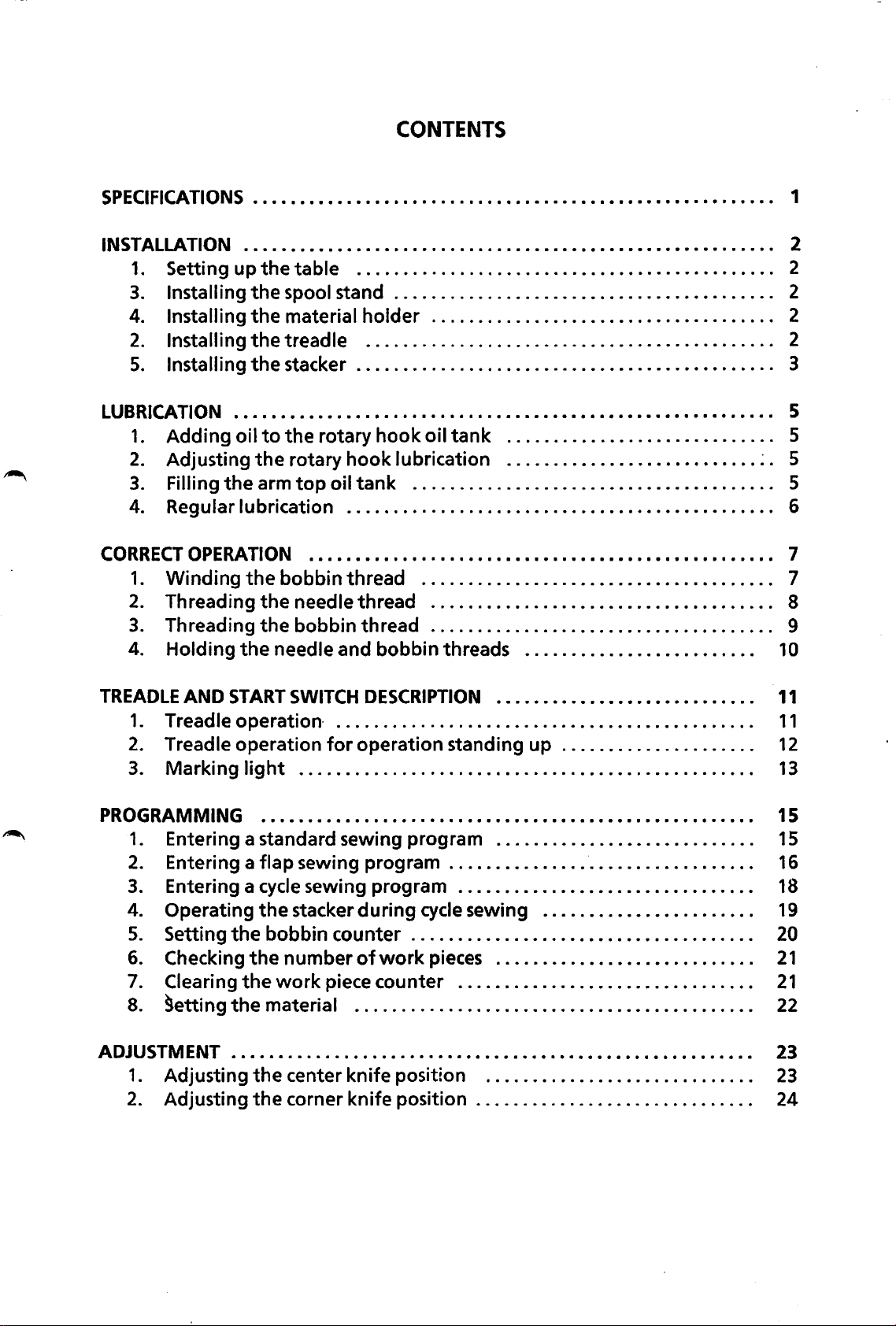
Page 1
AUTOMATIC
LOCK
STITCH
POCKET
WELTING
SEWING
FLAP
SERVICE
BAS-600
BAS-601
MACHINE
FOR
ATIACHMENT
MANUAL
FOR
•.
Page 2
CONTENTS
SPECIFICATIONS
INSTALLATION . • • . • • • • • • • • • • . • • • • • • • • • • • . • • • • • • • • • . • • • • • • • • • • • • • • . • • • • • 2
1. Setting up
3.
Installing
4.
Installing
2.
Installing
5.
Installing
LUBRICATION
1.
Adding oil
2.
Adjusting
3.
Filling
4.
Regular lubrication . . . . . . . . . . . . . . . . . . . . . . . . . . . . . . . . . . . . . . . . . . . . . . 6
CORRECT
1.
2.
3.
4.
OPERATION
Winding
Threading
Threading
Holding
• . • • • • • • • • . • . • • • • • • • • • • . . • • • • . • . • • . • • • • • • • • • • • • • • • • • • • • • 1
the
table . . . . . . . . . . . . . . . . . . . . . . . . . . . . . . . . . . . . . . . . . . . . . 2
the
spool stand . . . . . . . . . . . . . . . . . . . . . . . . . . . . . . . . . . . . . . . . . 2
the
material holder . . . . . . . . . . . . . . . . . . . . . . . . . . . . . . . . . . . . . 2
the
treadle . . . . . . . . . . . . . . . . . . . . . . . . . . . . . . . . . . . . . . . . . . . . 2
the
stacker . . . . . . . . . . . . . . . . . . . . . . . . . . . . . . . . . . . . . . . . . . . . . 3
. • • . • • • • . . • . • • • • . . • • • • • • • . . . • • • • • • • • • • • • • • • . • • • • • • • • • • • • • • 5
to
the
the
the
the
rotary
the
rotary hook lubrication
arm
top
...•.••.•••••••••••••••••••.•••••••.••••••••
bobbin thread . . . . . . . . . . . . . . . . . . . . . . . . . . . . . . . . . . . . . . 7
the
needle thread . . . . . . . . . . . . . . . . . . . . . . . . . . . . . . . . . . . . . 8
the
bobbin thread . . . . . . . . . . . . . . . . . . . . . . . . . . . . . . . . . . . . . 9
needle and bobbin threads . . . . . . . . . . . . . . . . . . . . . . . . .
oil
hook
tank
oil
tank
. . . . . . . . . . . . . . . . . . . . . . . . . . . . . 5
...........................
~
. 5
. . . . . . . . . . . . . . . . . . . . . . . . . . . . . . . . . . . . . . . 5
I • • • • • 7
10
TREADLE
1. Treadle
2.
3. Marking
PROGRAMMING • • . • • . • • • • • • • • • • • • • • • • • • • • • • • • • • • • • • • • • • • • • • • • • • • • • • • 15
1. Entering a standard sewing program . . . . . . . . . . . . . . . . . . . . . . . . . . . .
2. Entering a flap sewing program . . . . . . . . . . . . . . . . . . . . . . . . . . . . . . . . .
3.
4. Operating
5.
6.
7.
8.
ADJUSTMENT • . • • • • . • . • • • . • • • • • • • • • • • • • • • • • • • . • • • • • • • • • • • • • • • • • • • • • • •
1. Adjusting
2.
AND
START
SWITCH
operation
Treadle operation
light
Entering a
Setting
the
Checking
Clearing
9etting
the
the
Adjusting
the
. . . . . . . . . . . . . . . . . . . . . . . . . . . . . . . . . . . . . . . . . . . . . . . . . 13
cycle
sewing program . . . . . . . . . . . . . . . . . . . . . . . . . . . . . . . .
the
stacker during
bobbin counter . . . . . . . . . . . . . . . . . . . . . . . . . . . . . . . . . . . . .
number
work
material . . . . . . . . . . . . . . . . . . . . . . . . . . . . . . . . . . . . . . . . . . .
the
center knife
the
corner knife position . . . . . . . . . . . . . . . . . . . . . . . . . . . . . . 24
DESCRIPTION
• • • • • • • • • • • • • • • • • • • • • • • • • • • •
. . . . . . . . . . . . . . . . . . . . . . . . . . . . . . . . . . . . . . . . . . . . .
for
operation standing up . . . . . . . . . . . . . . . . . . . . .
cycle
sewing . . . . . . . . . . . . . . . . . . . . . . . 19
of
work
pieces . . . . . . . . . . . . . . . . . . . . . . . . . . . .
piece counter . . . . . . . . . . . . . . . . . . . . . . . . . . . . . . . .
posit~
on . . . . . . . . . . . . . . . . . . . . . . . . . . . . .
11
11
12
15
16
18
20
21
21
22
23
23
Page 3
DISASSEMBLY
1. Removing
2.
Removing
3.
Removing
4.
Removing
5.
Removing
6.
Removing
7.
Removing
••••.•••.••••••••••••••••••••••••••••••••••••••••••••••
the
cloth guide (left)
the
binder
the
face plate
the
machine head
the
carriage feed mechanism
the
feed mechanism
the
padding cloth presser assembly
.........................................
......................................
................................
..................................
........................
................................
...................
25
.
27
.
27
.
28
.
29
.
30
.
31
.
32
ASSEMBLY
1.
Attaching
2.
Attaching
3.
Attaching
4.
Attaching
5.
Attaching
6.
Attaching
7.
Attaching
8.
Attaching
9.
Attaching
1
0.
Other
SEWING FLOW CHART
•••.•.•.••..•••••••••••••••••..•••••••••••••••••••••••••••
the
the
the
the
the
(Same
attachment method
the
the
the
the
.......................................................
1. Backtacking
2.
Condensed stitch
3.
Stacker operation
4. 1/0 checking
5.
DIP
switch descriptions (supplement)
6.
Relationship between machine speed and feed speed
to
due
stitch pitch
feed mechanism assembly
machine head
face plate
binder
cloth guide
movable knife assembly
fixed knife assembly
carriage feed assembly
padding cloth presser
•••••••••••••••••••••••••••••••••••••••••••••••••
.................................................
.................................................
.........................................
.............................................
............................................
.........................................
...................................
................................•..•...
for
both
........................
right
..........................
.............................
......................•..•..
foot
...........................
and
left
....................•...
sides)
.......
33
33
.
35
.
36
37
.
37
.
38
.
39
.
~
40
42
42
.
43
43
.
44
.
45
.
46
.
47
.
48
.
STANDARD ADJUSTMENT
1. Adjusting
2.
Adjusting
3.
Adjusting
4.
Adjusting
5.
Adjusting
the
6.
Adjusting
7.
Adjusting
8.
Adjusting
9.
Adjusting retention
(Required
10.
Adjusting
11. Adjusting
12.
Adjusting
the
the
the
the
the
bobbin
the
the
the
the
the
the
(MECHANICAL
upper and
needle and
gap between
needle bar
gap between
case
opener
carriage feed mechanism
binder
cloth guide
to
assure
center knife assembly
movable knife assembly
fixed knife assembly
lower
the
the
lift
the
...................................•.
..........................................
.....................................
thread remainder
PORTION)
shaft timing
rotary
stroke and
hook
rotary
rotary
.............................
••••••••••••••••••••••
.....................
timing
hook
hook
............................
and
the
needle bar
and
........................
for
sewing start.)
..........................
................
the
needle plate
height
.....
.......
..
49
49
.
49
.
so
so
so
.
51
.
55
.
56
.
57
.
58
.
64
.
67
Page 4
13.
Adjusting
14.
Adjusting
15.
Adjusting
16.
Adjusting
17.
Adjusting
18.
Adjusting
19.
Adjusting
the
corner knife . . . . . . . . . . . . . . . . . . . . . . . . . . . . . . . . . . . . . .
the
padding cloth presser
the
tension release . . . . . . . . . . . . . . . . . . . . . . . . . . . . . . . . . . . 78
the
pickup type stacker . . . . . . . . . . . . . . . . . . . . . . . . . . . . . . .
the
bar stacker . . . . . . . . . . . . . . . . . . . . . . . . . . . . . . . . . . . . . . . 84
the
foot
switch . . . . . . . . . . . . . . . . . . . . . . . . . . . . . . . . . . . . . .
the
flap sensor (model
foot
601
. . . . . . . . . . . . . . . . . . . . . . . .
only) . . . . . . . . . . . . . . . . . . . . . . .
70
76
79
85
86
STANDARD
1.
2.
3.
OPTIONAL
1.
2.
3.
4.
5.
TROUBLESHOOTING
ERROR
ADJUSTMENT
Replacing
Replacing
Connecting
PARTS
the
the
the
INSTALLATION • • • • • • • • • • • • • • • • • • • • • • • • • . • • • • • • • • • • • • • 95
Thread breakage detector . . . . . . . . . . . . . . . . . . . . . . . . . . .
Flap guide . . . . . . . . . . . . . . . . . . . . . . . . . . . . . . . . . . . . . . . . . . . . . . . . . . . .
Spacer
for
working
Hand switch . . . . . . . . . . . . . . . . . . . . . . . . . . . . . . . . . . . . . . . . . . . . . . . . . .
Marking lights . . . . . . . . . . . . . . . . . . . . . . . . . . . . . . . . . . . . . . . . . . . . . . . .
CODES
• . • • • • • • • • • • • • • • • • • • • • • • • • • • • • • • • . • • • • • • • • • • • • • • • • • • • • 1
(ELECTRONIC
PORTION)
. • • • . • • • • . • • • • • • • • • • • • •
circuit board . . . . . . . . . . . . . . . . . . . . . . . . . . . . . . . . . . . . .
fuse . . . . . . . . . . . . . . . . . . . . . . . . . . . . . . . . . . . . . . . . . . . . .
solenoid valves and the air lines . . . . . . . . . . . . . . . . . . 94
..
. . . . . . . . . .
while
GUIDE
standing up . . . . . . . . . . . . . . . . . . . . . . . . . . . 96
• • • • . • • • • • • • • • • • • • • • • . • . • • • • • • • • • • • • . • • • • • . • 98
87
87
93
95
95
96
97
OS
Page 5
SPECIFICATIONS
Model 151-600
Machine head LT2-B833
Sewing speed
Flap sewing No
Needle
Gauge size
Seam
length
2500 spm (variable
Mtx
Standard
Gauge size
twin
190
#16(#16-#18)
10 mm (8, 12,
Flap stitch
needle, lockstitch
to
2200 spm
14, 16,
to
14mm
from
16
mm
80-180
with
18,20 mm)
28-190 mm
36-190
mm
*
Lockstitch
Backstitch Condensed 0.8-1.4 mm
Stitch
length
Thread
Power supply 3-phase 220V, 50/60Hz, 500W (21ines
Dimensions
type
Thread
820 D X 1300 W X 1155 H mm
1.4-2.8
Backtack Same
for
automatic sewing
mm
(Stitch
(Adjusted
length
as
lockstit
at
sewing
with
DIP
machines (spun core #50)
I
DIP
switch setting)
I
mm
ch
start
is
1/2 lockstitch stitch length.)
switch setting.)
of
3-phase supply used)
151-601
Yes
- 1-
Page 6
INSTALLATION
1.
Setting up the table
2. Installing
the
treadle
* Set
*
the
Loosen
adjust
Lock
the
Lower
Lower
* Remove
panel@.
Plug
the
the
side panel connector block.
machine table on a level surface.
the
nut 0 I and turn
the
height.
casters so
the
lever@
the
Ievere
the
12Pconnectore
the
to
to
three
screws 0 I and open
table will
lock
move
the
caster @
not
move.
the
caster@.
the
table.
forthetreadle@
the
to
side
into
-2-
4. Installing the material holder
* Set
the
material holder 0 onto
secure with
the
screw@).
the
stud @ and
Page 7
5.
Installing the
stacker
Installing
* Refer
the
to
bar
the
type
figure
stacker
below
to
install
the
stacker.
0 Connector No. 14
@ Connector No.
@)
Airhose
e
Airhose
15
Connecting
* Connect
the
power
the
connectors
supply connector and
as
numbered.
the
air
hoses
-3-
Page 8
Installing
the
pickup type stacker
* Refer
Connecting
to
the
figure below
the
power supply connector and the
* Connect the connectors
to
install the stacker.
as
numbered.
air
0 Connector No.
@ Connector No.15
@)
Airhose
9 Airhose
hoses
14
Air
pressure adjustment
1.
Increase
Decrease
The standard operating
Turn
the
handle 0
2.
If
water
cock @ 1 and
direction
*
collects in
of
Be
sure
letting
-4-
turn
the
to
the
to
the
the
arrow
close
water
air
pressure
adjust the pressure.
bottle
drain cock e slowly in
to
drain
the
drain
out.
is
@
close
1
the
water.
cock 9
5 kg/cm2.
the
air
the
after
Page 9
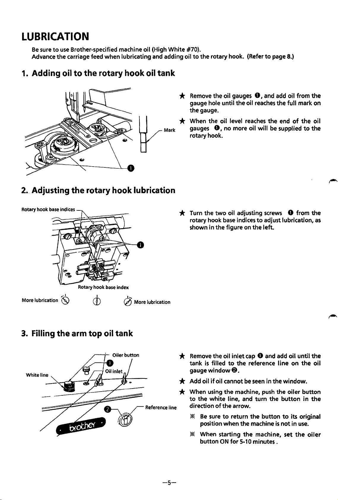
LUBRICATION
Be
sure
to
use
Brother-specified machine oil (High White #70).
Advance the carriage feed when lubricating and adding oil
to
the rotary hook. (Refer
to
page 8.)
1. Adding oil
2. Adjusting
Rotary hook base indices
to
the rotary hook oil tank
the
rotary hook lubrication
*
Remove
gauge hole until the oil
the gauge.
* When the oil level
Mark
gauges
rotary hook.
* Turn the
rotary hook
shown in the figure on the left.
the oil gauges
reaches
0,
no more oil
two
oil adjusting
base
indices
0,
and add oil from the
reaches
will
to
the full mark on
the end
be
screws
adjust lubrication,
of
supplied
0 from the
the
to
oi I
the
as
More lubrication
3. Filling
White
line
Rotary hook base index
..-:1
(SJ
the
arm top oil tank
I
CD
~
More
lubrication
*
Remove
tank
gauge
* Add oil
the oil
is
filled
window@.
if
oil cannot
* When using
to
the white line, and
direction
*
* When starting
of
Be
sure
position when the machine
button
inlet
cap
0 and add oil until the
to
the reference line on
be
seen
the
machine,
the arrow.
to
return the button
the
ON
for
5-10
push
turn
machine, set
minutes.
the
in the window.
the oiler button
the
button
to
is
not
in
its original
in
use.
the
oil
the
oiler
-5-
Page 10
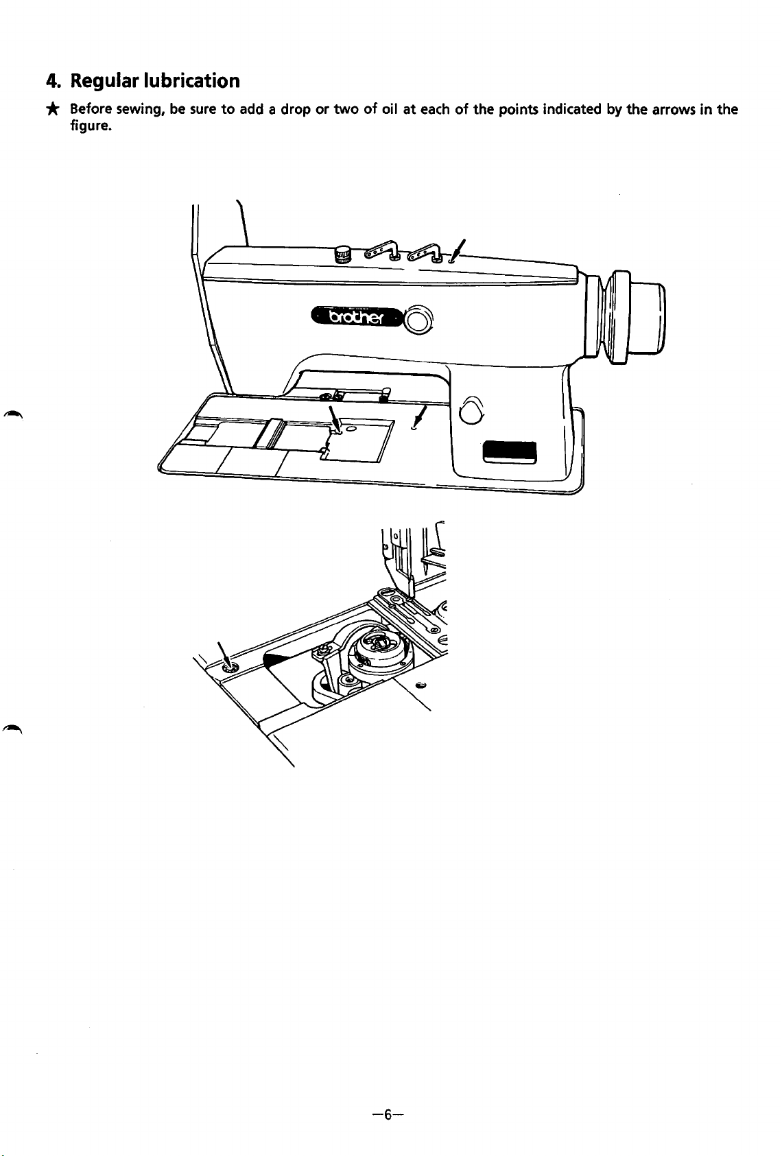
4.
Regular
lubrication
* Before sewing,
figure.
be
sure
to
add
a drop or
two
of
oil
at
each
of
the points indicated by the arrows in the
1------
a
l
..
-6-
Page 11
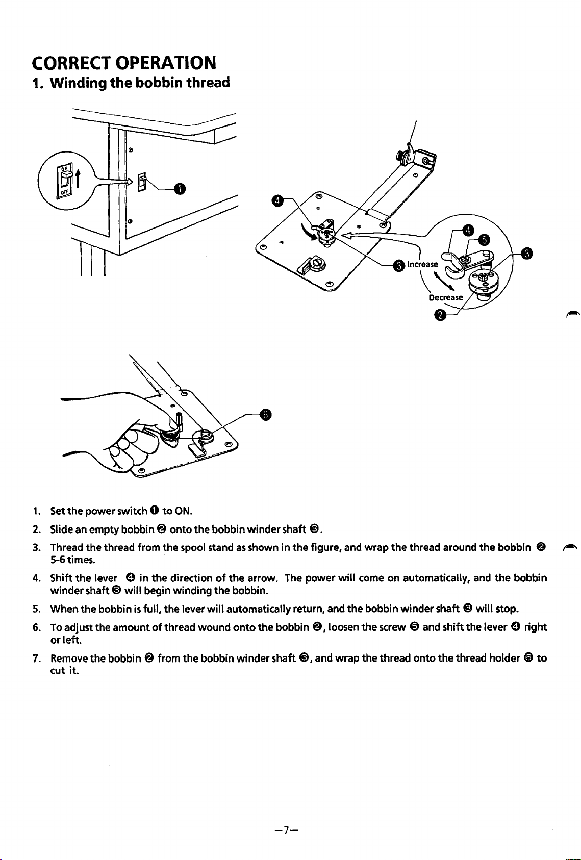
CORRECT
OPERATION
1. Winding the
bobbin
thread
1.
Set
the
power switch 0
2.
Slide an empty bobbin@
3.
Thread
5-6times. ·
4.
Shift
winder
5.
When
6.
To
or
7.
Remove
cut
the
thread from the spool stand
the
lever e in
shaft@)
the
adjust the amount
left.
the bobbin @ from
it.
will
bobbin
to
ON.
onto
the
direction
begin winding
is
full,
the
lever
of
thread wound
the
the bobbin winder shaft
as
shown
of
the
arrow. The power
the
bobbin.
will
automatically return, and
onto
bobbin winder shaft
the
in
the
bobbin
@),
@.
figure, and wrap
will
come on automatically, and
the
8,
loosen
and wrap the thread onto
the
thread around
bobbin winder shaft
the
screw
@>
the
bobbin 8
the
bobbin
@)
will
stop.
and shift the lever e
the
thread holder ~ to
r-"
right
-7-
Page 12
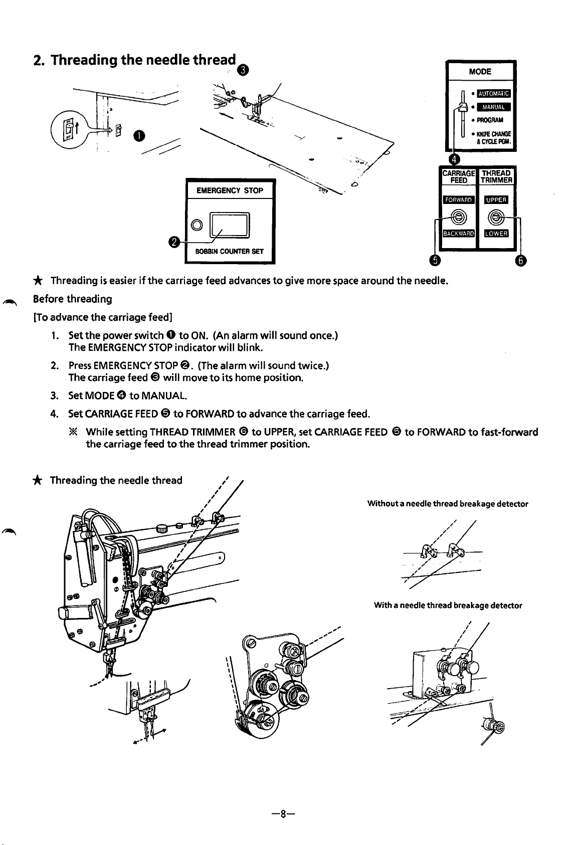
2.
Threading the needle
threa~
t)
MODE
•
«·im•IMiil+
•lf.t.Uiit.iW
•
PROGRAM
•
KNIFE
CHANGE
&CYa.EPGM.
~
* Threading
Before
[To advance
threading
the
1.
Set
the
The
EMERGENCY
2.
Press
The carriage feed
3.
SetMODEe
4.
Set
CARRIAGE
*
While
the
is
easier
carriage feed]
power
EMERGENCY
carriage feed
if
switch 0
to
MANUAL.
FEED@)
setting
the
STOP
BOBBIN
COUNTER
carriage feed advances
to
ON.
(An alarm
indicator
STOP@. (The alarm
@
will
move
to
FORWARD
THREAD
to
the
will
to
its home position.
TRIMMER
thread
trimmer
SET
blink.
will
to
advance
@to
to
give more space around
will
sound once.)
sound twice.)
the
carriage feed.
UPPER,
set
position.
CARRIAGE
the
FEED @ to
CARRIAGE
FEED
needle.
FORWARD
THREAD
TRIMMER
to
fast-forward
* Threading
the
needle thread
Without
a needle thread breakage detector
With
a needle thread breakage detector
-8-
Page 13
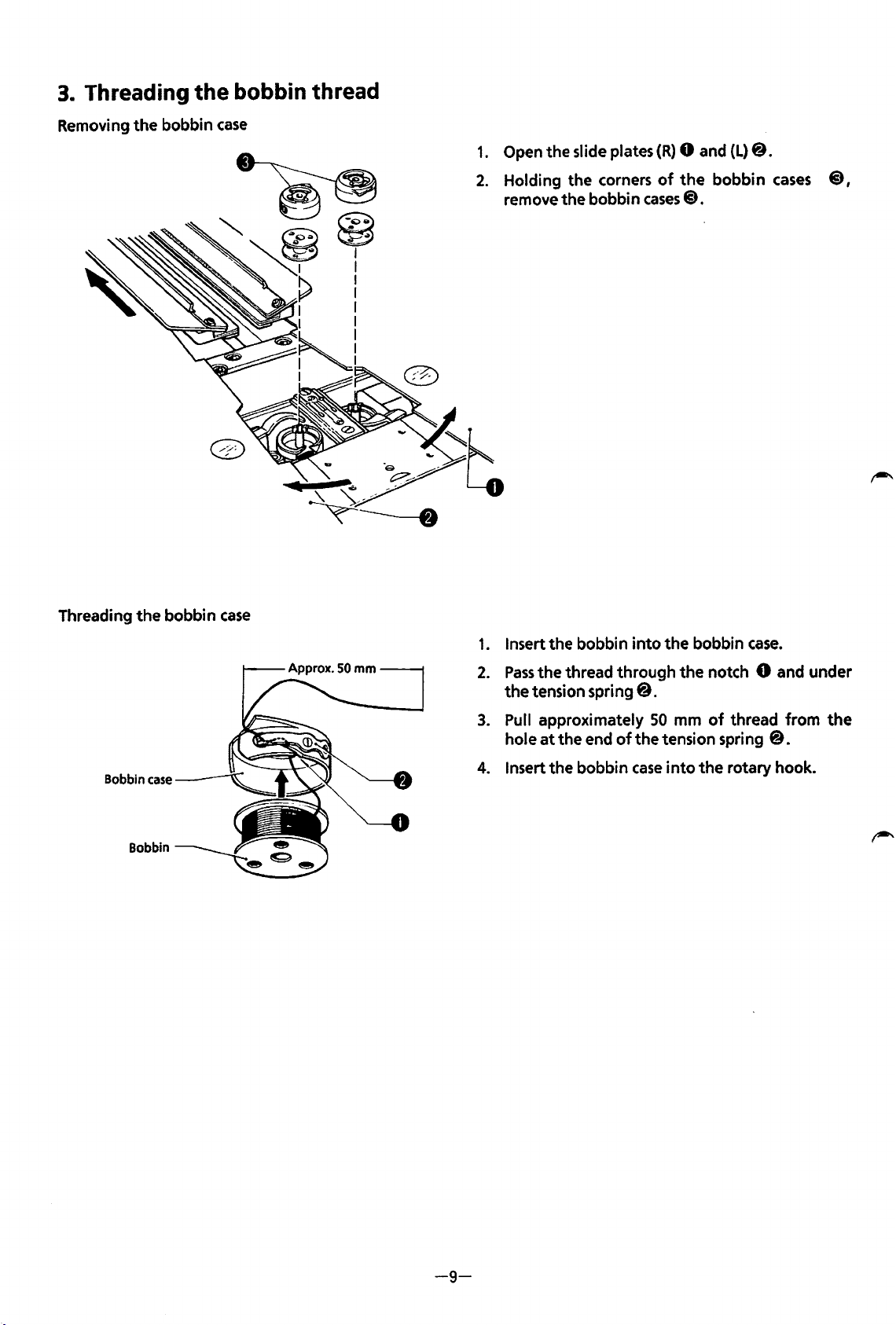
3.
Threading the bobbin thread
Removing the bobbin
case
1.
Open the slide plates
2.
Holding the corners
remove the bobbin
(R)
0 and
of
the
cases@.
(L)
@.
bobbin
cases
@,
Threading
Bobbin
the
case
Bobbin
bobbin
case
1.
Insert the bobbin
2.
Pass
the
thread through
the
tension spring@.
3.
Pull approximately
hole
at
the end
4.
Insert the bobbin
into
the bobbin
the
notch 0 and under
50
mm
of
of
the tension spring
case
into
the
case.
thread from
@.
rotary hook.
the
-9-
Page 14
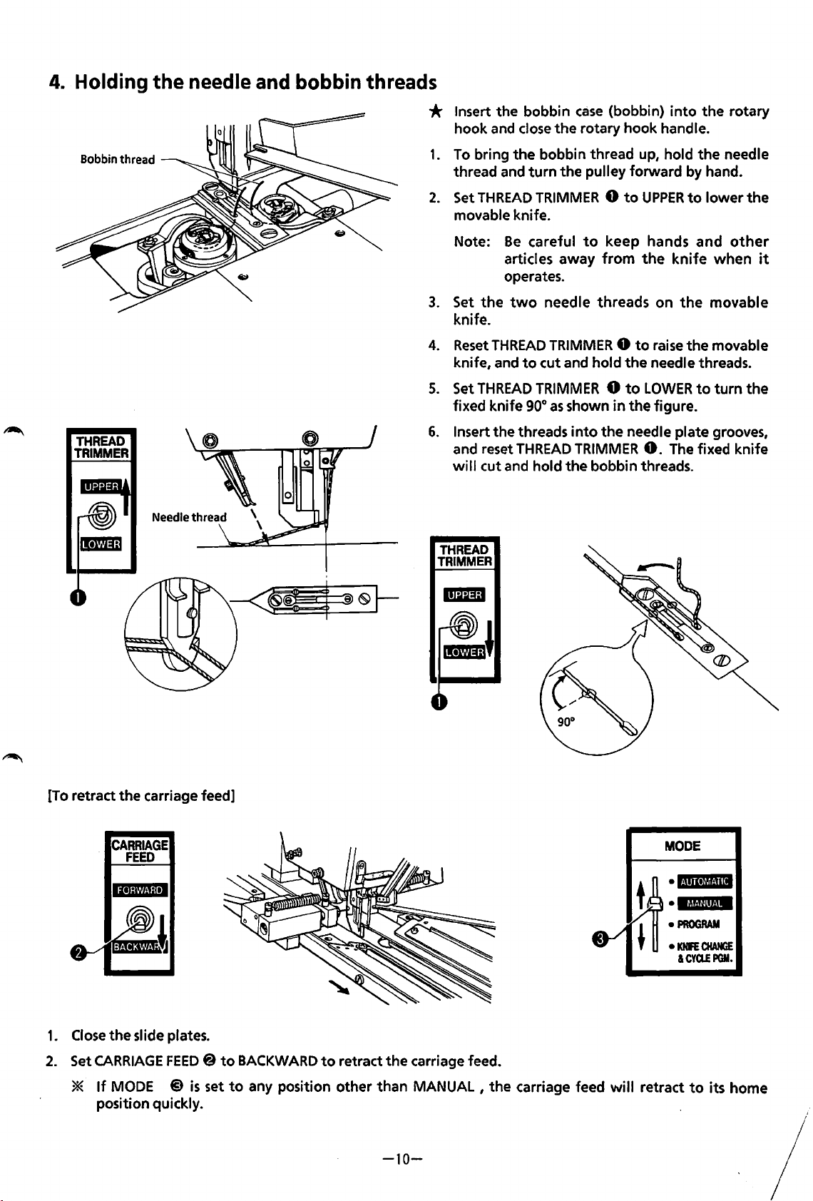
4. Holding
the
needle and bobbin threads
Bobbin thread
THREAD
TRIMMER
* Insert the bobbin
hook
and
close
the rotary hook handle.
1.
To
bring the bobbin thread up, hold
turn
thread and
2.
Set
THREAD
movable knife.
Note:
3.
Set
knife.
4.
Reset
knife,
5.
Set
fixed knife
6.
Insert the threads
and reset
wi
Be
articles away
operates.
the
THREAD
and
THREAD
II
cut
and
two
THREAD
the pulley forward by hand.
TRIMMER 0 to
careful
needle threads on
TRIMMER 0 to
to
cut and hold
TRIMMER 0 to
90°
as
hold the bobbin threads.
case
(bobbin)
to
keep hands and
from
the
shown in the figure.
into
the needle plate grooves,
TRIMMER
into
UPPER
the
0.
to
knife
the
raise
the
needle threads.
LOWER
The
the rotary
the
needle
lower the
other
when
movable
movable
to
turn
fixed knife
it
the
[To
retract the carriage feed]
CARRIAGE
FEED
THREAD
TRIMMER
MODE
•l·iiiitiij.Jil
• 16t.!ilit4M
•
PROGRAM
•
KNfE
CHANGE
&CYa.EPGM.
1.
Close
the
slide plates.
2.
Set
CARRIAGE
*
If
MODE
position quickly.
FEED 8 to
@)
is
set
BACKWARD
to
any position other than
to
retract
the
carriage feed.
MANUAL,
the carriage feed will retract
-10-
to
its home
Page 15
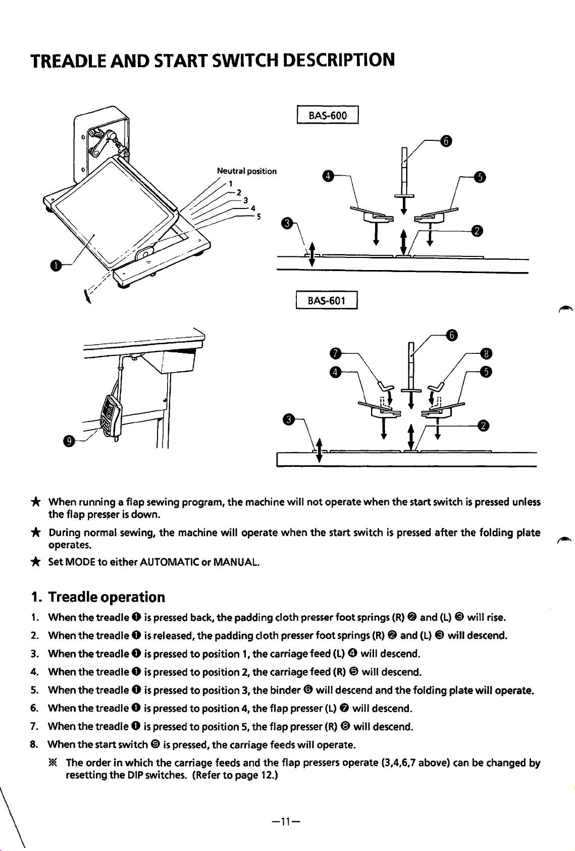
TREADLE
AND
START
SWITCH
DESCRIPTION
BAS-600
BAS-601
* When running a
the
flap
pres~er
flap
sewing program,
is
down.
* During normal sewing,
operates.
* Set MODE
1. Treadle operation
1.
When
2.
When
3.
When
4.
When
5.
When
6.
When
7.
When
8.
When
* The order
resetting
to
the
treadle 0
the
treadle 0
the
treadle 0
the
treadle 0
the
treadle 0
the
treadle 0
the
treadle 0
the
start switch
either AUTOMATIC
is
pressed back,
is
released,
is
pressed
is
pressed
is
pressed
is
pressed
is
pressed
€)
in
which
the
the
DIP
switches. (Refer
the
machine
to
to
to
to
to
is
pressed,
carriage feeds and
will
or
MANUAL.
the
the
padding cloth presser
position
position
position 3,
position 4,
position
the
to
the
machine
operate
padding cloth presser
1,
the
2,
the
the
the
5,
the
carriage feeds
page 12.)
will
not
when
the
carriage feed
carriage feed
binder@
flap
presser
flap
presser
will
the
flap
pressers
operate
start switch
foot
will
(L) 8 will
(R)@)
operate.
when
the
start switch
is
pressed
foot
springs
springs
(L) 9 will
(R)
@)
will
descend and
will
operate (3,4,6,7 above) can be changed by
(R)
(R)
@ and
descend.
descend.
the
descend.
descend.
after
@ and
(L) @ will
folding
is
pressed unless
the
folding
(L) @ will
descend.
plate will operate.
plate
rise.
-11-
Page 16
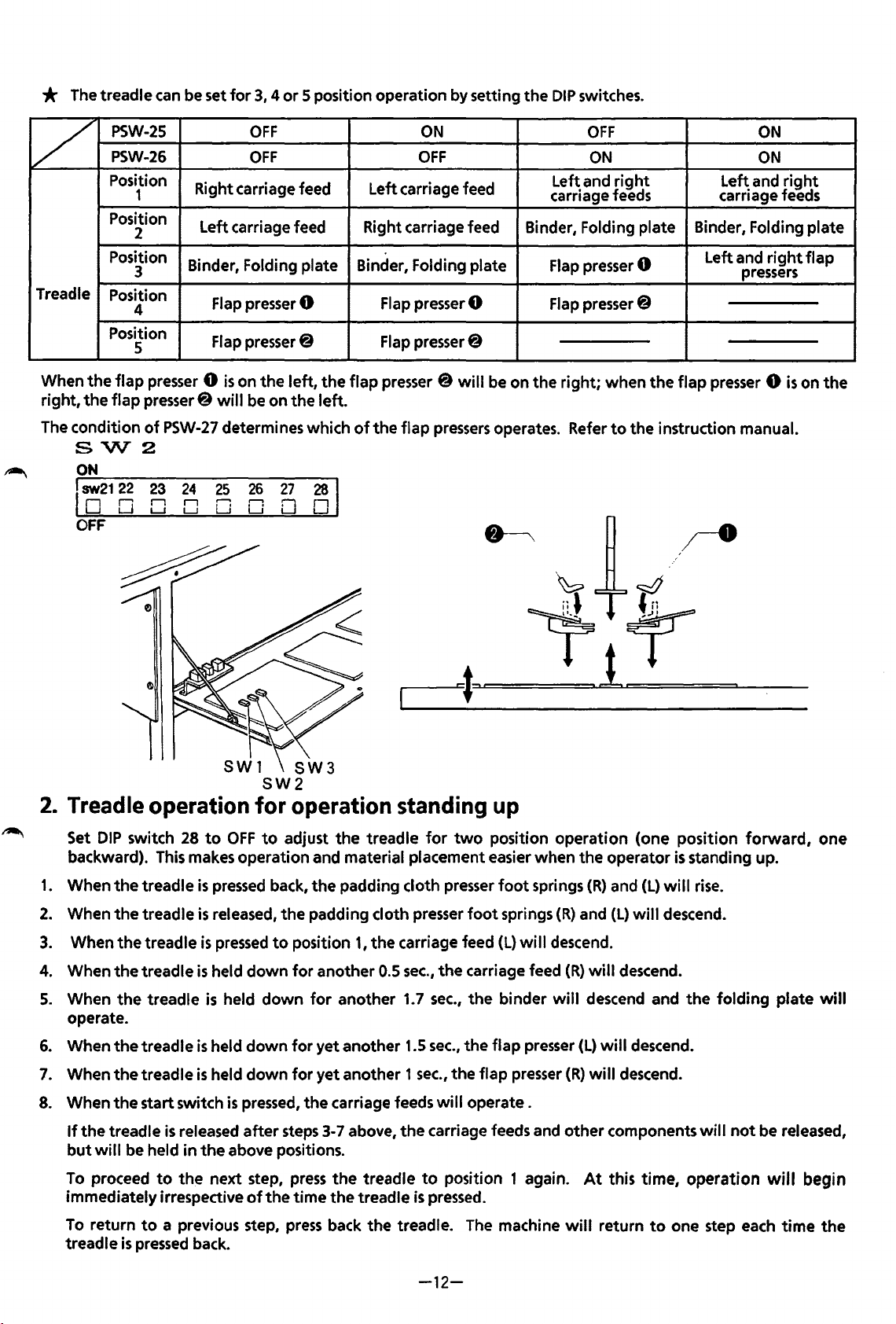
* The treadle can be set
for
3, 4 or
5 position operation by setting
the
DIP
switches.
/
Treadle
When
right,
The condition
~
the
the
SW2
PSW-25
PSW-26
Position
1
Position
2
Position
3
Position
4
Position
5
flap
presser 0
flap
presser@
of
PSW-27
23
r1
L...J L...J u
~
OFF
OFF
Right carriage feed Left carriage feed
Left carriage feed Right carriage feed
Binder, Folding plate Binder, Folding plate
Flap presser 0 Flap presserO Flap presser@
Flap presser@ Flap presser@
is
on
the
left,
the
flap
will
be on
the
left.
determines which
25
0
26
,.......,
24
r1
27
0
28
n
L...J
of
the
ON
OFF
presser @
flap
pressers
Binder, Folding plate Binder, Folding plate
will
be on
operates. Refer
Left and
carriage feeds carriage feeds
Flap presser 0
the
right;
~
~
OFF
ON ON
right
Left and
when
the
flap
presser 0
to
the
instruction manual.
ON
Left and
pressers
,r-8
~
right
right
is
flap
on
the
2. Treadle operation
~
Set
DIP
switch 28
backward). This makes operation and material placement easier when
1.
When
the
treadle
2.
When
the
treadle
3.
4.
5.
6.
7.
8.
When
When
When
operate.
When
When
When
the
treadle
the
treadle
the
treadle
the
treadle
the
treadle
the
start switch
to
OFF
is
pressed
is
released,
is
pressed
is
held
is
held
is
held
is
held
is
SW2
for
to
adjust
back,
the
to
down
down
down
down
pressed,
.--------=rl===..=:!:::::L=!
operation standing up
the
treadle
the
padding cloth presser
padding cloth presser
position
for
for
for
the
1,
the
another 0.5
for
another 1.7
yet
another
yet another 1
carriage feeds
for
two
foot
carriage feed
sec.,
the
carriage feed
sec.,
the
1.5
sec.,
the
sec.,
the
flap presser
will
operate .
position
foot
springs
(L)
binder
flap
~t=
=:::::::a..__
operation
springs
wi
II
descend.
will
presser
the
(R)
(R)
and
(R)
descend and
(L)
(R)
operator
and
(L)
will
descend.
will
will
descend.
(one
position
is
(L)
will
will
descend.
descend.
forward,
standing up.
rise.
the
folding
plate
one
will
If
the
treadle
but
will
To proceed
immediately irrespective
To
return
treadle
is
released
be held
is
pressed back.
in
to
the
to
a previous step,
after
the
above positions.
next step,
of
the
steps 3-7 above,
press
the
treadle
time
the
treadle
press
back
the
the
carriage feeds and
to
position 1 again.
is
pressed.
treadle. The machine
other
will
-12-
components
At
this
return
will
time,
operation
to
one step each
not
be released,
will
begin
time
the
Page 17
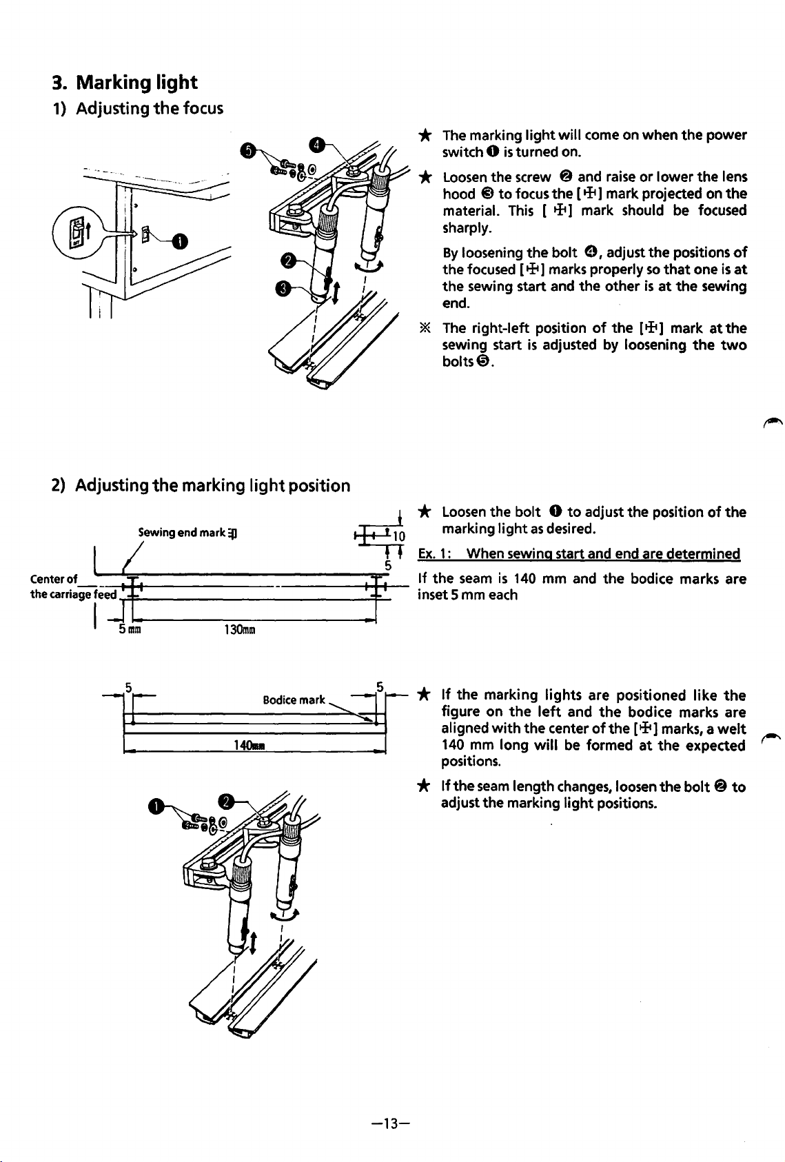
3.
Marking light
1) Adjusting
2)
Adjusting
the
the
focus
marking
light
position
*
The
marking
switch
*
Loosen
hood @
material.
sharply.
By
loosening the
the focused [ + 1 marks properly
the sewing start and the other
end.
*
The
right-left position
sewing start
bolts@.
light
will come on when the power
0
is
turned on.
the screw @ and
to
focus the [ + 1 mark projected on
This
[ + 1 mark should
bolt
e I adjust the positions
is
adjusted by loosening
raise
or lower the lens
so
is
at
of
the [ tft 1 mark
be
that
the
the
focused
one
is
sewing
at
the
the
two
of
at
Centerof
thecarriagef.!j
I 5
.,.
_____________
mm
*
Loosen
marking
Ex.
1:
If
~
--tj
130mm
5
Bodicemark~
1408
the
inset 5 mm
If
the marking lights are positioned like
*
figure on
aligned
140
positions.
*
If
the
adjust the marking
the
bolt 0 to
light
as
When sewing start and end are determined
seam
is
140
mm and the bodice marks are
each
the
left
with
the center
mm long
seam
will
length
adjust the position
desired.
and
the
of
the
be
formed
changes,
light
loosen the
positions.
of
bodice marks are
[tli1
marks, a
at
the expected
welt
bolt @ to
the
the
-13-
Page 18
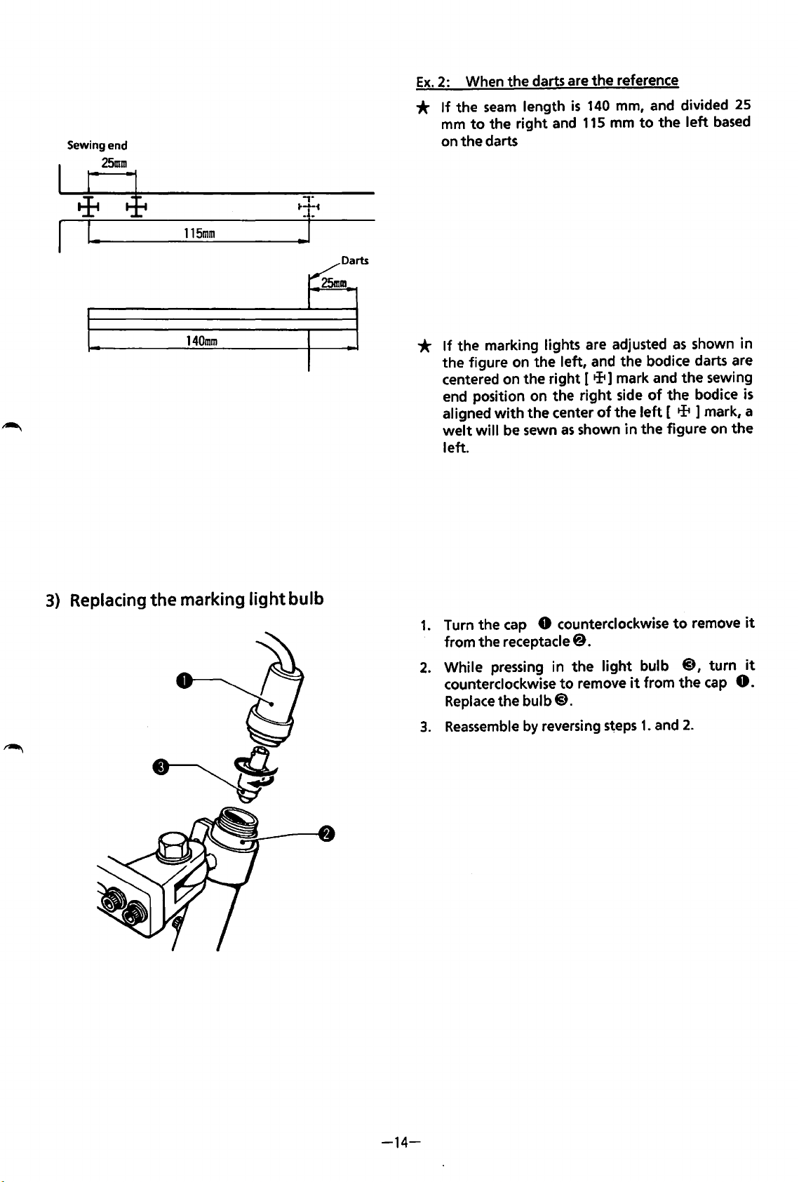
Sewing end
25mm
4 l
I.
115mm
,.
J
Darts
~~
Ex.
2:
*
If
the
mm
on the darts
When the darts are the reference
seam
to
the right
length
and
is
140
115
mm,
mm
to
and
the
divided 25
left
based
3)
Replacing
the
140mm
marking
light
bulb
*
If
the marking lights are adjusted
the figure on the left,
centered on the right
end
position
aligned
welt
will
left.
1.
Turn the
from the receptacle@.
2.
While
counterclockwise
Replace
3.
Reassemble
on
the right
with
the center
be
sewn
cap
8 counterclockwise
pressing
the bulb@.
in the
by
reversing s'eps
as
shown in the figure on the
to
remove
as
and
the bodice darts are
[tit]
mark
and
side
of
the bodice
of
the
left
[ tit 1 mark, a
to
light
bulb
it
from the
1.
and
shown in
the sewing
is
remove
@,
turn
cap
0.
2.
it
it
-14-
Page 19
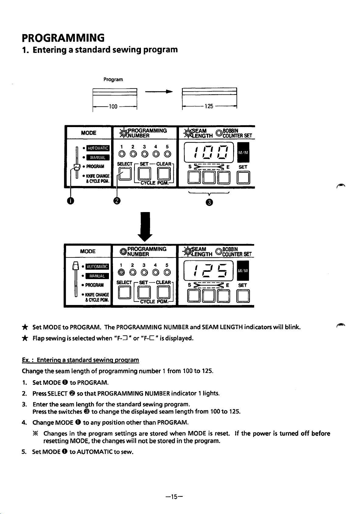
PROGRAMMING
1. Entering a standard sewing program
Program
I~-------.
MODE
•I·~!II•JII·!ill
el.f,t@if.jM
•
PROGRAM
•
KNFE
CHANGE
&CYQ!PGM.
.ROO
1 2
©@@(Q)@
sruCT[O-DJ
RAMMING
UMBER
3
CYCLE
.EAM
4 5
PGM.
J
MODE
1
•lllli~~Hil
•
'MUI*t.IM
•
PROGRAM
•
KNIFE
CHANGE
&CYCLEPGM.
~PROGRAMMING
NUMBER
1 2
@)@@@©
4
3
iEJ[{jLEtjJ
__
5
125
-----~~
ENGTH
I
f
S
~----<
(Q)BOBBIN
,-,
,-,
,_,
,_,
COUNTER
E
DOD
EAM
.<·
~ENGTH
I
1 C
S
:>
@BOBBIN
-,
,-
='
_____
< E
COUNTER
DOD
SET
I
SET
D
SET
I
SET
D
* Set MODE
* Flap sewing
Ex.: Entering a standard sewing program
Change
1.
Set MODE 0
2.
Press
3.
Enter
Press
4.
Change MODE 0
* Changes
resetting
5.
Set MODE 0
to
the
seam
SELECT@
the
seam
the
switches @
PROGRAM.
is
selected
length
to
in
MODE,
to
of
PROGRAM.
so
that
length
to
to
any position
the
program settings are stored
the
AUTOMATIC
The PROGRAMMING
when
"F-:J"
programming
PROGRAMMING
for
the
change
changes
to
or
standard sewing program.
the
displayed seam
other
will
sew.
NUMBER
"F-C"
number 1 from
not
is
NUMBER
than
PROGRAM.
be stored
displayed.
indicator 1 lights.
length
when
-15-
in
and
100
MODE
the
to
SEAM
125.
from
100
is
reset.
program.
LENGTH
to
125.
If
indicators
the
power
will
is
turned
blink.
off
before
Page 20
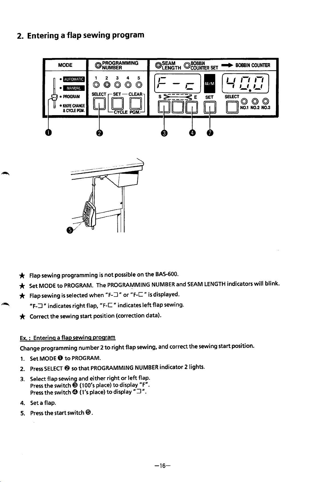
2.
Entering a
flap
MODE
sewing program
12\\
PROGRAMMING
~NUMBER
~SEAM
WPLENGTH
©BOBBIN
COUNTER
SET
...
BOBBIN
COUNTER
•
l·nmJbt.Ui
•
lt't("f!tt.!M
•
PROGRAM
•
KNIFE
CHANGE
&CYCLEPGM.
1 2 3 4 5
©~@©©
SELECT
1[f[j1
~CYCLE
PGM.!J
I I 1-1
-;
,-,
,_,
,_,
•
SELECT©
II
II
N0.1
© ©
N0.2
N0.3
* Flap sewing programming
* Set MODE
* Flap sewing
UF-:J
* Correct
Ex.
: Entering a
Change programming number 2
1.
SetMODEO
2.
Press
3.
Select
Press
Press
4. Set a flap.
5.
Press
to
PROGRAM.
is
selected
n indicates
the
SELECT@
flap
the
switch@
the
switch 9 (1's place)
the
start switch
right
sewing start position (correction data).
flap
sewing program
to
PROGRAM.
so
that
sewing and
The PROGRAMMING
when
flap,
PROGRAMMING
either
(100's place)
@).
is
not
"F-:J n
"F-C
to
right
to
possible
or
II
indicates
right
flap
or
to
display
display
on
the
BAS-600.
NUMBER
"F-C
II
is
displayed.
left
flap
sewing.
sewing, and correct
NUMBER
left
flap.
"F".
":J
".
indicator
and
2lights.
SEAM
LENGTH
the
sewing start position.
indicators
will
blink.
-16-
Page 21

EMERGENCY
0
/
BOBBIN
STOP
COUNTER
SET
«:)
6.
The
flap
sensor
The distance moved
7.
Set
CARRIAGE
the
sewing start (needle) position.
The carriage feed can move by
8.
Press
SET 8 after
The carriage feed
display
If
position
will
EMERGENCY
be stored.
but
the
will
detect
after
FEED
€)
the
sewing start position
will
STOP
correction data
CARRIAGE
FEED
the
flap edge, and
material edge detection
to
FORWARD
return
@
is
0.2
to
pressed
or
BACKWARD
mm increments.
its home position, and
without
will
not
be stored.
the
is
located.
pressing
I
.....
I
I
I
I
I
t-----------------]
I
I
.... I_,.
I
carriage feed
will
appear
to
move
the
correction data shown
SET
0,
will
move
in
the
BOBBIN
the
carriage feed
the
carriage feed
forward
COUNTER
so
40
that
in
will
mm
display:
the
return
and stop.
the
flap
BOBBIN
to
"40.0".
edge
is
COUNTER
its home
at
9.
Changes in
* Changes
*
the
program
in
the
resetting MODE,
If
the
only
change
will
be stored
program settings are stored
the
seam
length
to
be made
is
when
will
the
MODE 0
not
right
be changed.
or
when
left
flap
is
reset
to
any position
MODE 0
selection, steps 4-8 can be skipped.
is
reset.
If
other
the
than
power
PROGRAM.
is
turned
off
before
-17-
Page 22
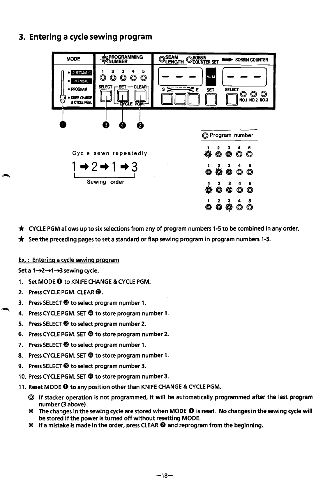
3.
Entering a cycle sewing program
MODE
• i·iliitjij.flli
•
l.jlaU!it·iM
•
PROGRAM
•
KNFE
CHANGE
I
CYClEPGM.
Cycle
sewn
repeatedly
1-+2-+1-+3
t
Sewing order
IR\SEAM
~LENGTH
IR\BOBSIN
Q.,COUNTER
SET
....
BOBBIN
[---)1(---]
S :;i
____
~
E
SET
DOD D D
@ Program number
1 2 3 4 5
-~-@@
1 2 3 4 5
ct-8©@
·~-@@
1 2 3 4 5
•••
SELECT@
N0.1
1 2 3 4 5
@©
COUNTER
@ @
N0.2 N0.3
*
CYCLE
*
See
Ex.
: Entering a cvcle sewing program
Seta
1.
Set MODE 0
2.
Press
3.
Press
4.
Press
5.
Press
6.
Press
7.
Press
8.
Press
9.
Press
10.
Press
11.
Reset MODE 0
@
* The changes
*
PGM
allows
the
preceding pages
1~2~1~3
CYCLE
SELECT@
CYCLE
SELECT@
CYCLE
SELECT @ to
CYCLE
SELECT@
CYCLE
If
stacker
number
be stored
If
a mistake
sewing cycle.
to
PGM. CLEAR@.
PGM.
PGM.
PGM.
PGM.
operation
(3 above) .
if
up
to
six selections
to
KNIFE
CHANGE & CYCLE
to
select program n!Jmber
SET 9 to
to
select program
SET 9 to
select program
SET 9 to
to
select program
SET 9 to
to
any position
is
in
the
sewing cycle are stored
the
power
is
made
in
from
any
of
program numbers 1-5
set a standard
store program
number
store program
number
store program
number
store program
other
not
programmed,
is
turned
the
order, press CLEAR@ and reprogram
than
off
or
flap
PGM.
1.
number
2.
number
1.
number
3.
number
KNIFE
it
without
sewing program in program numbers 1-5.
1.
2.
1.
3.
CHANGE & CYCLE
will
be automatically programmed
when
MODE 0
resetting MODE.
to
be combined
PGM.
is
reset. No changes
from
the
beginning.
in
any order.
after
the
in
the
sewing cycle will
last program
-18-
Page 23
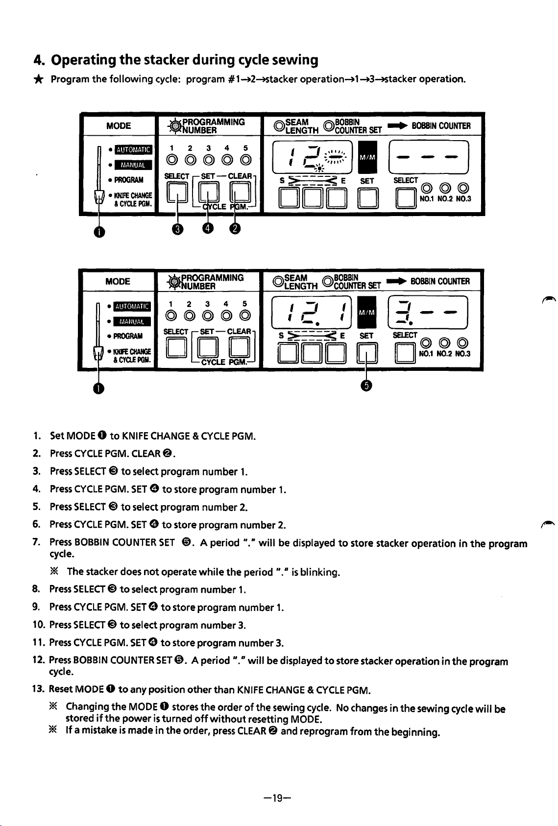
4.
Operating
the
stacker during cycle sewing
* Program
the
following
MODE
·l·!•ll·l~~!·mt
•13!-'fllf.!M
•
PROGRAM
~
~
•
KNIFE
&CYCLEPGM.
cycle: program #1_.2-+Stacker operation_.1_.3-+Stacker
•
ROGRAMMING
UMBER
4
3
CHANGE
1
2
©©@@@
il~?J
--
MODE
•l·l!ll•lt!!·lll
•
lf&Uilto!M
•
PROGRAM
~
~
•
KNFE
&CYa.EPGY.
CHANGE
.ROO
1
©©©©@
DQQCJ
RAMMING
UMBER
2 3
4 5
(Q)~~~TH
5
I
._,1
~
'
~\.,
~,
S
~---_s
DOD
©~~~~TH
I
-,
tC
>-_
•
___
S
DOD
operation
(Q)~g~~R
_,,,
''·
-~-
,,,,
,,,
..
©~g~~R
_s
E
I
'
E
SET
I
SET
D
SET
I
SET
..
BOBBIN
(-
SELECT©
II
..
BOBBIN
[
-,
-;-
-·
SELECT©
II II
-
II
N0.1
N0.1
.
COUNTER
-]
© @
N0.2 N0.3
COUNTER
-]
©@
N0.2 N0.3
4~
1.
Set MODE 0
2.
Press
CYCLE
3.
Press
SELECT@
4.
Press
CYCLE
5.
Press
SELECT @ to
6.
Press
·cYCLE
7.
Press
BOBBIN
cycle.
* The stacker does
8.
Press
SELECT@)
9.
Press
CYCLE
10.
Press
SELECT@
11.
Press
CYCLE
12.
Press
BOBBIN
cycle.
to
KNIFE
CHANGE &
PGM. CLEAR@.
to
select program
PGM.
SET 9 to
select program
PGM.
SET 9 to
COUNTER
to
PGM.
to
PGM.
COUNTER
SET
not
operate
select program
SET 9 to
select program
SET 9 to
SET@. A period
CYCLE
number
store
program
number
store
program
@.
A
period"."
while
the
number
store program
number
store
program
PGM.
1.
number
2.
number
period
1.
number
3.
number
II.
n
will
1.
2.
will
be displayed
"."
is
blinking.
1.
3.
be displayed
4~
to
store stacker
to
store stacker
operation
operation
in
in
the
the
program
program
,-..
13.
Reset MODE 0
* Changing
stored
*
If
a mistake
if
to
any position
the
MODE 0 stores
the
power
is
made
is
turned
in
the
other
than
KNIFE
CHANGE & CYCLE
the
order
of
the
sewing cycle. No changes
off
without
order, press CLEAR@ and reprogram
resetting MODE.
-19-
PGM.
from
in
the
the
beginning.
sewing cycle
will
be
Page 24
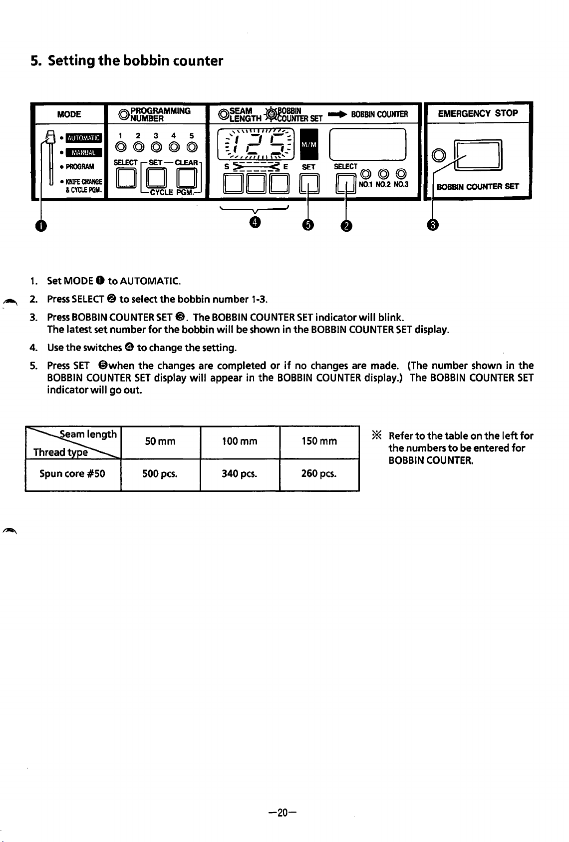
5.
Setting
the
bobbin counter
~
MODE
B
·1·!'11•1!!·!111
•IMU!IHM
•
PROGRAM
•
KNIFE
&CYCLE
4,
1.
Set MODE 0
2.
Press
3.
Press
The latest set
4.
Use
the
5.
Press
BOBBIN
indicator
CHANGE
PGM.
to
SELECT@
BOBBIN
SET
COUNTER
number
switches 9
@when
COUNTER
wi
II
go
@PROGRAMMING
NUMBER
1 2
@@@©@
4
3
ocetCJ
@~g~TH
5
,,,,._
...
'I
: f
,-
,..
,_,,,,,,,. ,,.,
s~---~E
DOD
'
..!'''''''"
-,
~
v
e
AUTOMATIC.
to
select
the
to
SET
out.
bobbin
SET@. The BOBBIN
for
the
bobbin
change
the
changes are completed
display
the
will
number
will
setting.
appear
1-3.
COUNTER
be shown
in
the
.83W~
,-
-;:
~-
or
BOBBIN
SET
...
~
..
in
if
J
SET
the
no
(
I
~~2£2
indicator
BOBBIN
changes are made. (The
COUNTER
BOBBIN
COUNTER
will
blink.
COUNTER
display.) The
l
SET
EMERGENCY
~~
BOBBIN
COUNTER
~-
display.
number
BOBBIN
COUNTER
STOP
shown
SET
in
the
SET
~
Spun core
e
#50
SOmm
500
pes.
100mm
340
pes.
150mm
260
pes.
* Refer
the
numbers
BOBBIN
to
the
table
COUNTER.
on
to
be entered
the
left
for
for
-20-
Page 25
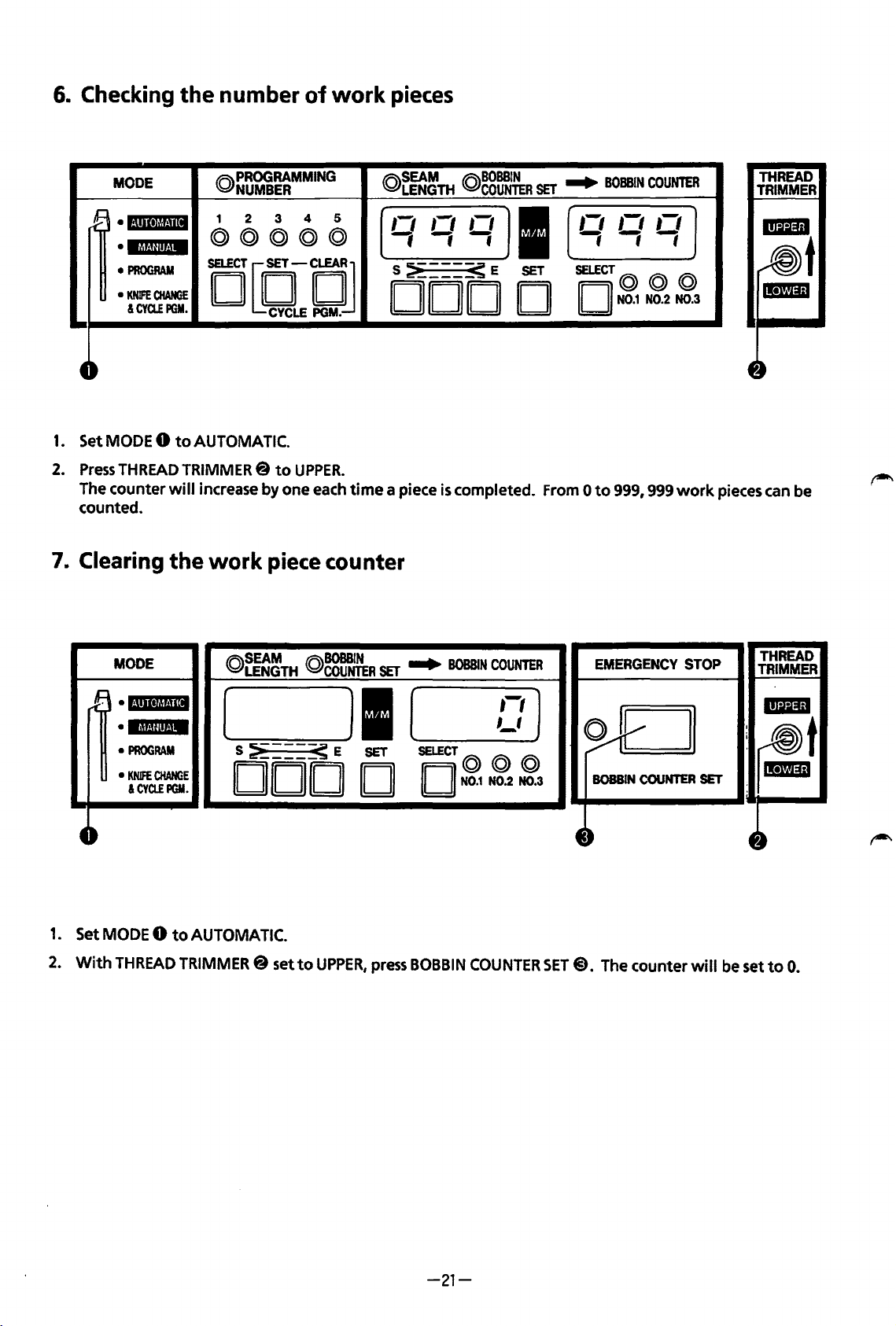
6.
Checking
the
number
of
work
pieces
rB
t-
1.
Set
2.
Press
The
counted.
7.
Clearing
MODE
·l·!•ll•lrll·llll
•IM!Jin·iM
•
PROGRAM
•
KNIFE
CHANGE
&CYCLEPGM.
MODE 0 to
THREAD
counter
TRIMMER@
will
the
@PROGRAMMING
NUMBER
1 2 3
@@@@@
4 5
DCClCJ
AUTOMATIC.
to
UPPER.
increase by one
work
each
piece counter
@r~~TH
,-,
fff
s~---~E
DOD
time a piece
@gg~~R
,-,
,,
I
SET
D
is
completed.
SET
...
,-,
-,-,-;
SELECT@
II II
From 0 to
BOBBIN
COUNTER
,-,
N0.1
N0.2 N0.3
999,
999
,-,
@ @
work
pieces
THREAD
TRIMMER
can
be
1.
2.
MODE
rB
•l·llll•lt!!·llll
•
MMU!it·IM
•
PROGRAM
•
KNifE
&CYCLEPGM.
4-
Set
MODE 0 to
With
THREAD
CHANGE
AUTOMATIC.
TRIMMER@
(Q)SEAM
LENGTH
@BOBBIN
COUNTER
[
S
~---~
E
DOD
set
to
UPPER,
SET
Jl
SET
D
press
...
B0BB1
(
SELECT@
II
II
N0.1
BOBBIN
COUNTER
N
COUNTER
,-,)
,_,
@@
N0.2 N0.3
~
4~
SET@).
EMERGENCY
v
BOBBIN
COUNTER
The
counter
STOP
SET
will
THREAD
TRIMMER
-
:
rm!t
:I!Di1
4~
be
set
to
0.
-21-
Page 26
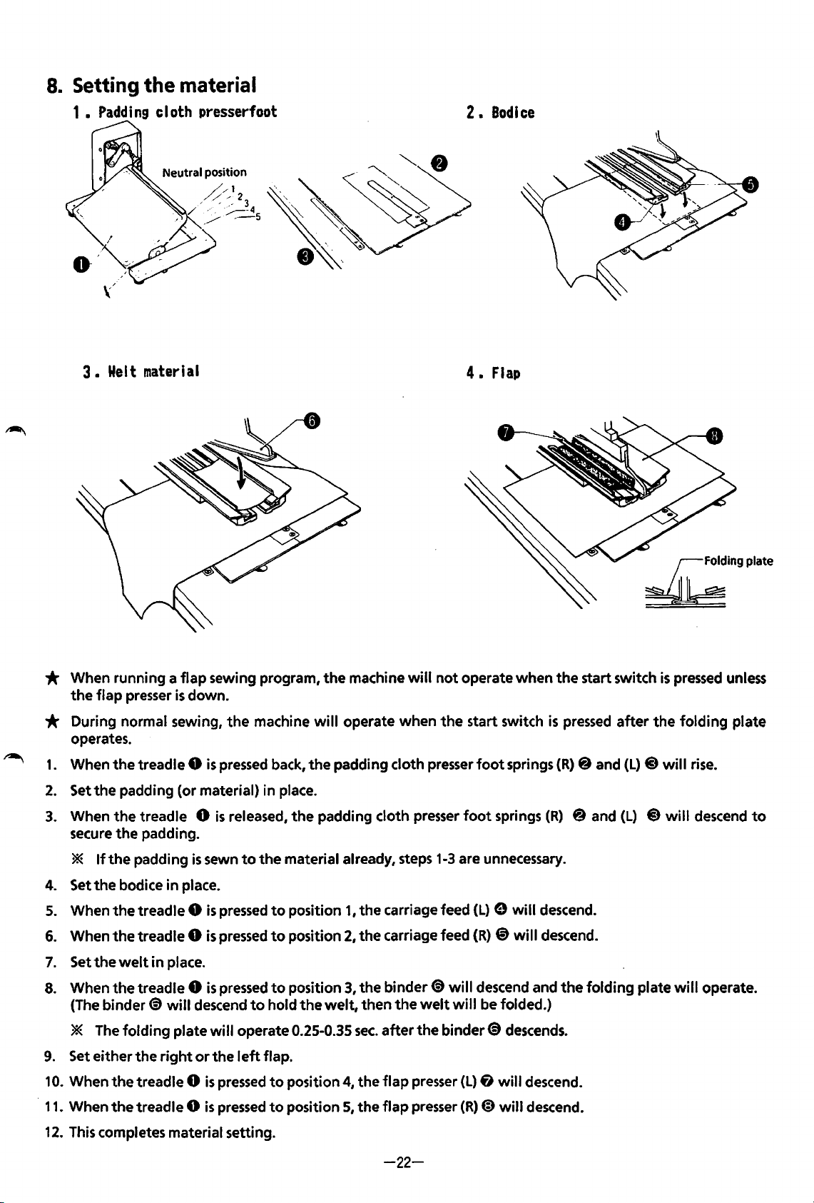
8.
Setting
1 •
Padding
3 •
Wei t material
the
material
cloth presserfoot
2.
4.
Bodice
Flap
* When running a
the
flap
presser
flap
sewing program,
is
down.
* During normal sewing,
operates.
1.
When
the
treadle 0
2.
Set
the
padding (or material) in place.
3.
When
secure
*
4. Set
5.
When
6.
When
7.
Settheweltinplace.
the
treadle 0
the
If
the
padding
the
bodice in place.
the
treadle 0
the
treadle 0
padding.
is
is
sewn
is
is
the
pressed
is
released,
to
pressed
pressed
the
machine
machine
the
to
to
will
operate when
back,
the
padding cloth presser
the
padding cloth presser
material already, steps
position 1 I
position
2,
the
the
will
not
the
1-3
are unnecessary.
carriage feed
carriage feed
operate
start switch
foot
when
foot
springs
springs
(L) e will
(R)
@)
will
the
start switch
is
pressed
(R)
@ and
(R)
@and
descend.
descend.
£ingplate
is
after
the
(L) @ will
(L)
@will
pressed
folding
rise.
descend
unless
plate
to
8.
When
9.
Set either the
10.
When
·
11.
When
12.
This completes material setting.
the
(The
binder~
* The
folding
the
the
treadle 0
will
plate
right
treadle 0
treadle 0
is
pressed
descend
will
operate 0.25-0.35
or
the
left
is
pressed
is
pressed
to
to
hold
flap.
to
to
position
the
welt,
position
position
3,
the
binder~
then
the
sec.
after
4,
the
flap
5,
the
flap
will
descend and
welt
will
be folded.)
the
binder~
presser
presser
(L)
(R)
fJ
@)
descends.
will
will
-22-
the
descend.
descend.
folding
plate
will
operate.
Page 27
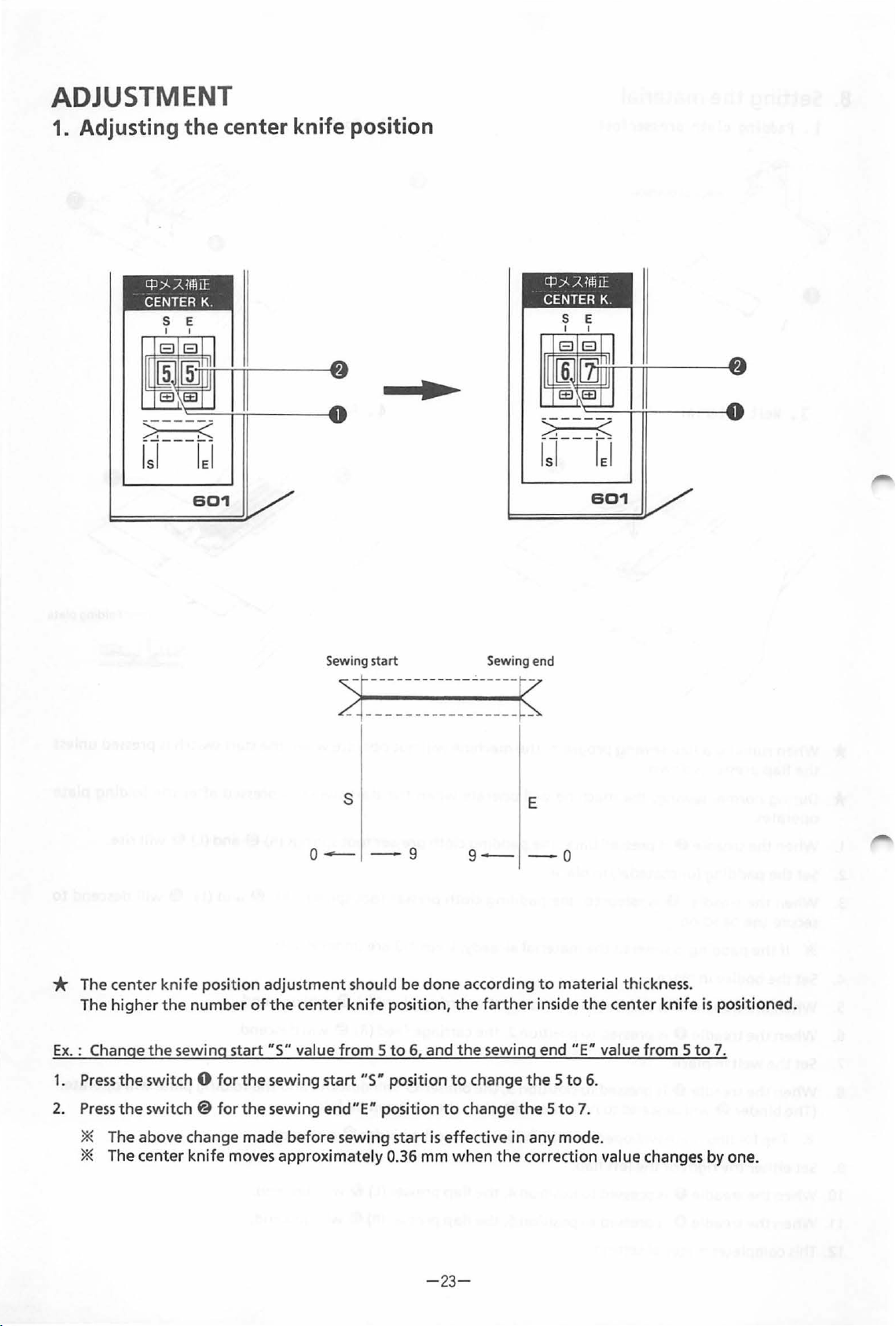
ADJUSTMENT
1. Adjusting
cp
;>(.
CENTER K.
the
.:;z
Uli
center knife position
iE
601
..
cp
)I.
:;z
1fli
iE
CENTER K.
601
* The center
high
The
Ex.
: Change
1.
Press
2.
Press
er
the
switch 0
the
switch@
the
Sewing
sta
rt
~------------~-
-
-------
--------
s
o
---
knife
position adjustment should be done according
the
number
sewing start
for
for
of
the
center
"5"
value
the
sewing start
the
sewing end"E" position
-9
knife
position,
from 5 to
"5"
position
6,
and
to
Sewing
--
9-
the
farther
the
sewing end
to
change
change
end
--~
--
-
E
-o
to
inside
the 5 to
the 5 to
material thickness.
the
"E"
6.
7.
center
value
knife
from 5 to
is
positioned.
7.
* The above change made before sewing start
* The center
knife
moves approximately 0.36 mm
is
effective
when
-
23-
in
any mode.
the
correct
ion
value changes by one.
Page 28
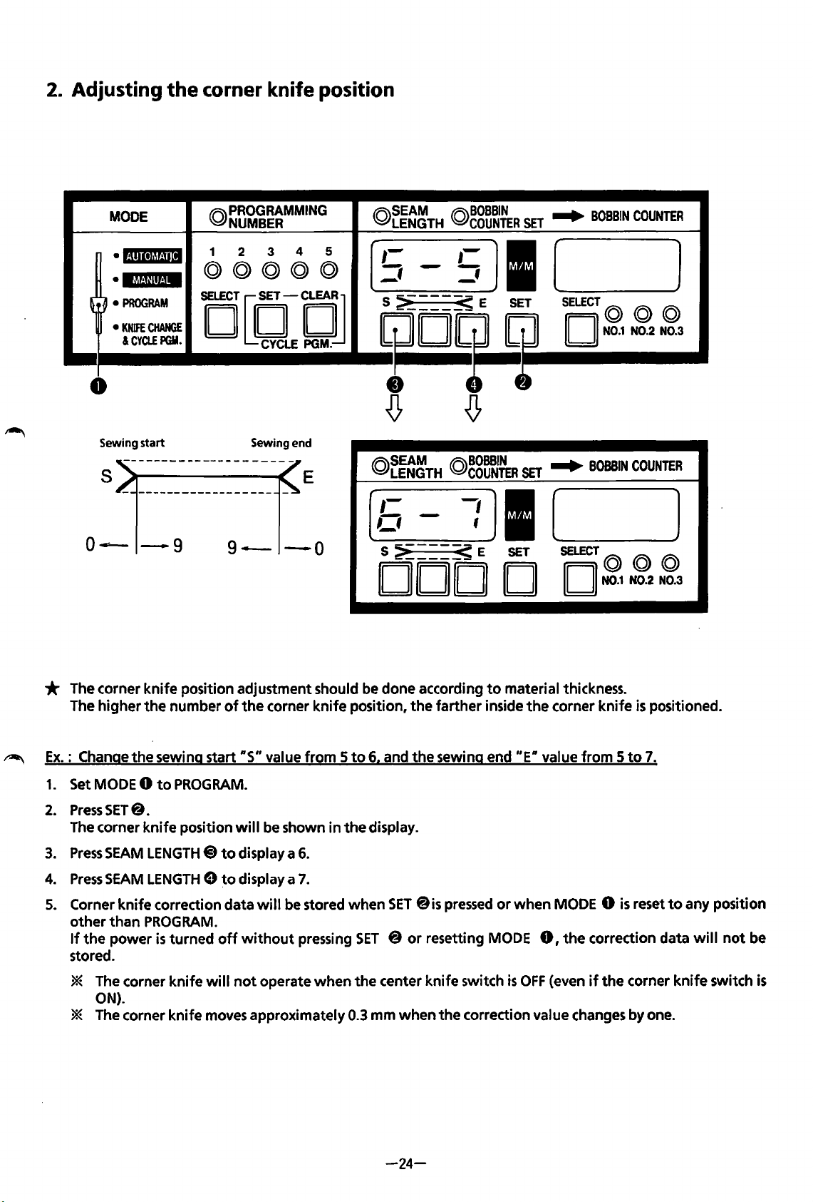
2.
Adjusting the
corner
knife
position
MODE
•
l·!lll•lt*l~·!il
•IMUIIJ.!M
(~
•
PROGRAM
~
•
KNIFE
CHANGE
&CYCLEPGM.
l
@PROGRAMMING
NUMBER
1
2 3
©)@@©@
iD[DfDJ
CYCLE
0
Sewing
start
S E
o~
-9
9-
Sewing
end
-o
4 5
PGM.
@SEAM
LENGTH
,-
-,
-
S
~----~
@BOBBIN
,-
_,
- -
COUNTER
I
SET
E
4JD
'
@~~~TH
_,;
S
~---~
DODD
@~8~~
__
: I [
E
SET
SET
...
B
0
BBIN
CO
UNTER
(
SELECT
~
SET
...
II
(Q) (Q)
II
N0.1
BOBBIN
@
N0.2
N0.3
COUNTER
_____
SELECT
(Q)
II II
N0.1
@@
N0.2
N0.3
)
)
* The corner
~
Ex.: Change
1.
2.
3.
4.
5. Corner
knife
The
higher
Set MODE 0
Press
The corner
Press
Press
other
If
the
stored.
the
SET@.
knife
SEAM
SEAM
knife
than
power
the
sewing start
to
LENGTH@)
LENGTH 8 to
correction data will be stored
PROGRAM.
is
* The corner
ON).
* The corner
position adjustment should be done according
number
PROGRAM.
position
turned
knife
knife
of
the
corner
RS"
value
will
be shown
to
display a
display a 7.
off
without
will
not
operate
moves approximately 0.3
knife
from 5 to
in
the
6.
pressing
when
position,
when
SET @ or
the
the
6. and
display.
SET
center
mm
when
farther
the
sewing end
@is pressed
resetting MODE
knife
the
to
material thickness.
inside
the
corner
"ER
value
or
when
MODE 0
0,
switch
correction value changes by one.
is
OFF
(even
knife
from 5 to
is
the
correction data
if
the
corner
is
positioned.
7.
reset
to
any position
will
not
knife
switch
be
is
-24-
Page 29
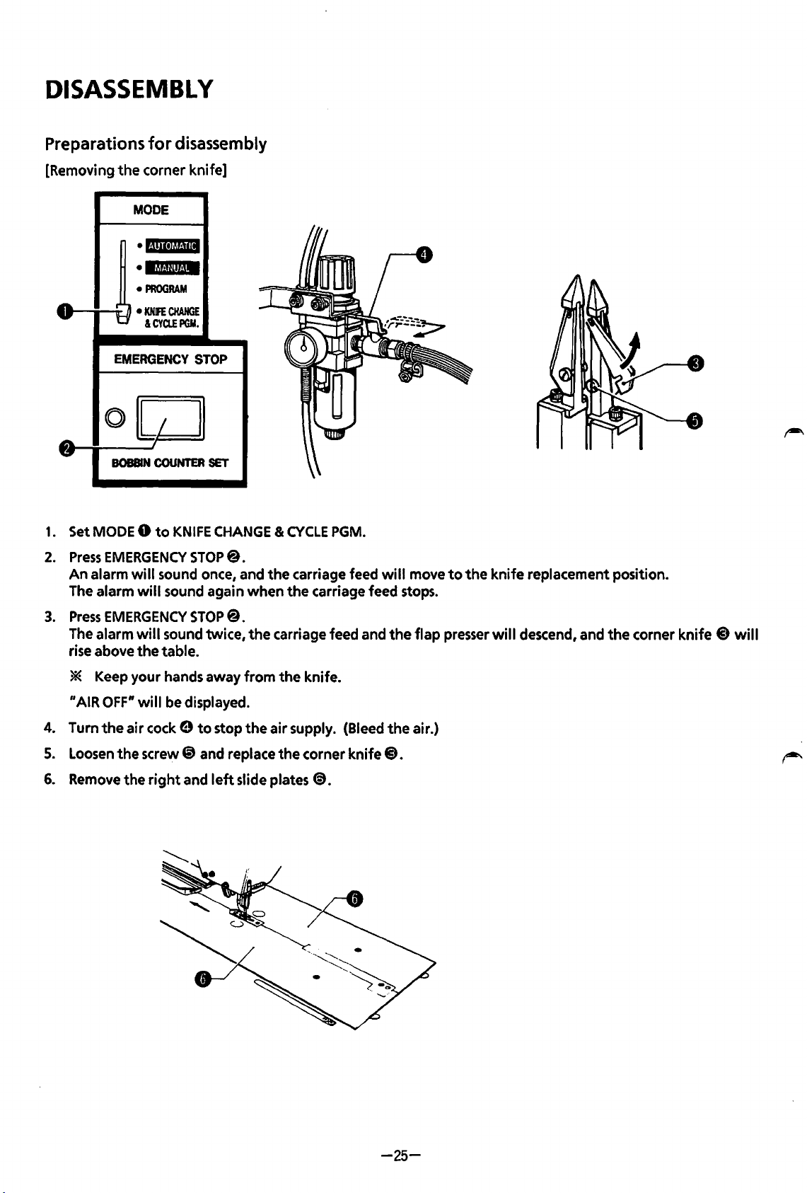
DISASSEMBLY
Preparations
[Removing
the
MODE
•1·!111·1~!·111
• ltl!·llll!·l·
•
..
v
· 9 •
EMERGENCY
0
~
""
1.
Set MODE 0
BOBBIN
for
disassembly
corner
PROGRAM
KNIFE
&CYa.EPGM.
knife]
CHANGE
I I
I
COUNTER
to
KNIFE
STOP
SET
CHANGE & CYCLE
PGM.
2.
Press
An
alarm
The alarm
3.
Press
The alarm
rise above
* Keep
"AIR OFF"
4. Turn
5.
Loosen
6.
Remove
EMERGENCY
will
sound once, and
will
sound again
EMERGENCY
will
sound
the
table.
your
hands away
will
be displayed.
the
air
cock 9
the
screw@) and replace
the
right
and
STOP@.
STOP@.
twice,
to
stop
left
slide plates
the
carriage feed
when
the
carriage feed stops.
the
carriage feed and
from
the
knife.
the
air
supply. (Bleed
the
corner
8.
knife
will
the
the
8.
move
flap
air.)
to
the
presser
knife
replacement position.
will
descend, and
the
corner
knife @ will
-25-
Page 30
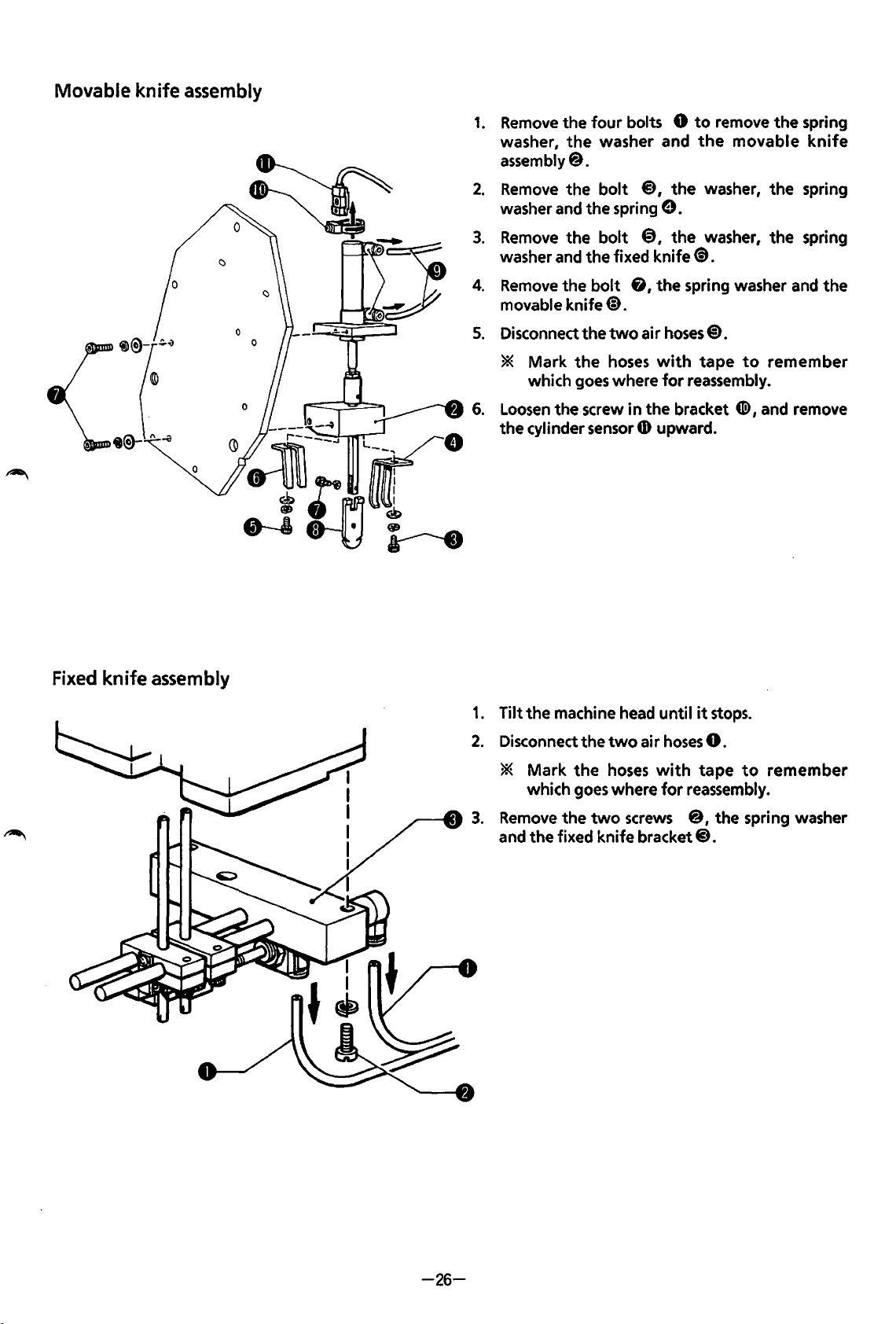
Movable
knife
assembly
1.
Remove
washer,
assembly@.
2.
Remove
washer
3.
Remove
washer
4.
Remove
movable knife@.
5.
Disconnect the
the four bolts 8
and
and
the
the
washer and
the
bolt
@,
the spring
the bolt
the fixed knife(!).
bolt
two
e.
@,
&, the spring washer
air
hoses@).
to
remove the spring
the
movable
the washer, the spring
the washer, the spring
knife
and
the
Fixed
knife
assembly
* Mark the
which
6.
Loosen
the
1.
Tilt the machine
Disconnect the
the
cylinder
* Mark the
which
Remove
and the fixed knife
the
goes
screw
sensor
goes
two
hoses
two
hoses
with
where
where
for
in the bracket
4D
upward.
head
until
air
hoses
with
for
screws
bracket@.
tape
to
reassembly.
4D>,
it
stops.
8.
tape
to
reassembly.
@,the
spring washer
remember
and remove
remember
-26-
Page 31

1.
Removing
the
cloth
guide (left)
1.
Remove
2.
Loosen
spacer@.
3.
Remove
2.
Removing
the
the
the
two
screws
two
screws
two
screws
the binder
8
@)
€}
the
flap sensor and
1
in
the
set collar @.
in
the
cloth guide arm e I then remove
the
sensor bracket.
Remove
the
1.
set collar
the
cloth guide & .
Remove
washers and
two
@I
the
cloth guide arm e and
bolts 01 the
the
binder assembly@.
spring and
the
flat
-:-27-
Page 32

3.
Removing
the
face
plate
~
1.
2.
Remove
Loosen
the
the
bolt
bolt@
0
1
and remove
* When removing the ruler
Remove
3.
Remove the bearing
4.
fulcrum shaft
5.
Loosen
6.
Disconnect
Disconnect the
7.
Remove the three bolts
8.
*
the
nut
the
bolt
the
If
the
arm
spring and
8.
step
e, then remove the fulcrum shaft@), bearing
@).
4B
and remove
two
air
two
air
is
not
flat
washers. Turn
the
spring washer and
the
fitting
cover~,
hoses® from
hoses
4£3,
disassembled,
CD
the
two
the
from
three
the
the
two
washers.
ruler
fitting
plate
washers
connecting shaft Q).
the
the
flat
lift
the
cylinder assembly
plate @
@I
make sure
@),
bearing @),and arm
cylinder
center knife drive cylinder
and spring washers, then remove
4D.
arm and
tie
to
it
the
so
the
right.
does
not
cover~
cam
with
that
the
touch
other
parts.
and arm
fj,
washer
@.
a string, then remove
bolts
the
4£3
can
fj
to
the
«<D
and bearing
face plate
be loosened, and perform
left.
@.
CD
the
from
bolt,
the
the
-28-
Page 33

4. Removing
the
machine head
* This should be done
* Follow
removed.)
the
procedures below
after
removing
if
the
the
face plate and fixed knife assemblies from
face plate assembly
is
attached. (The fixed knife assembly
the
head.
has
been
1.
Disconnect
2.
Loosen
3.
Disconnect
4.
Disconnect
5.
Disconnect
6.
Remove the
7.
Tilt
the
8.
Remove
9.
Disconnect
10.
Lower the head from
the
two
air
the
screw@)
the
two
air hoses@ from
the
two
air
the
connector
two
bolts
machine head
the
V-belt.
the
detector connector @ from
hoses
@ from
and remove
hoses@)
Cli>
at
4D
and the lamp bracket@.
until
it
stops.
the
table.
the
the
cylinder sensor
the
and@)
the
from
back of
two
S-elbows
0.
e.
twoS-elbows@.
the
two
cylinder assemblies
the
machine head.
the
PCB.
-29-
~
~
f).
\
0
Page 34

5.
Removing
the carriage feed
mechanism
(1) Removing
*
Mark
the
the
hoses
air
with
hoses
tape
to
assure
correct reconnection.
1.
Disconnect
2.
Disconnect
3.
Disconnect
Disconnect
hoses
do
not
4.
Disconnect
(2) Removing
the
air
hoses@
the
two
air
the
two
air
the
air
hoses
have
to
the
four
air
the
carriage feed
from
the
speed control joints 0 on
hoses@)
hoses@)
be disconnected.)
hoses
4D
from
from
from
Q)
from
the
the
the
joints
the
the
right
joint@
joint~
speed control joints 0 on the
and
the
S-elbow 8 on
and
the
S-elbow & on
€)
and S-elbows 0 on
the
and
the
the
right
right
left
carriage feeds.
left
carriage feed.
right
carriage feed.
and
left
and
left
carriage feeds. (The
carriage feeds.
·
1.
Remove
the
two
bolts 0 and
the
carriage feed assembly
8.
-30-
Page 35

1.
Disconnect
2.
Loosen
3.
Remove
the
the
the
two
connectors@ in
two
bolts@ and remove
two
bolts@,
the
the
DC
motor
the
timing
flat
and spring washers, and
belt
assembly
9.
the
0.
DC
motor
assembly
0.
(2) Removing
(3) Removing
(4) Removing
the
corner
the
corner knife adjusting
the
feed mechanism assembly
knife
cylinder assembly
base
1.
Loosen
sensor@ downward.
2.
Disconnect
3.
Remove
washer and
the
screw 0 and remove
the
the
@.
* Mark
1.
Remove
2.
Remove
washers, and
the
reconnecti on.
the
the
the
air hoses@ and
two
bolts @),the washer,
the
corner knife cylinder assembly
hoses
with
spring
0.
two
bolts
the
corner knife adjusting
tape
@,
the
9.
to
flat
assure
and spring
cylinder
the
spring
correct
base
@.
,~
* Do
1.
2.
not
mechanism unless absolutely
Disconnect
Remove
mechanism
*
Be
sure
assembly@.
-31-
remove
the
air
hose
the
four
assembly@.
not
to
or
disassembly
necessary.
0.
bolts @ and
drop
the
feed mechanism
the
the
feed
feed
Page 36

7.
Removing
the padding
cloth
presser
I
I
I
•J
assembly
(1) Removing
1.
Disconnect
2.
3.
Loosen
Remove
the
the
(2) Removing
1.
Disconnect
2.
3.
Remove
Loosen
the
the
the
padding cloth presser
the
two
air
hoses
0.
two
screws@ and remove
two
bolts 9 and remove
the
padding cloth presser
the
air
hose
<D.
two
screws 8 and remove
two
screws@)
and remove
foot
spring
the
padding cloth presser
the
cylinder
the
padding cloth presser
the
cylinder assembly
assembly~
foot
spring (L)
(R)
foot
from the table.
foot
tiD
from the table.
spring
spring
(R)
(L)
8.
@)from
the
table.
-32-
Page 37

ASSEMBLY
1. Attaching
1.
Attach the feed
with
frame
2.
Insert the air hose@ into the S-elbow
*
The
adjusted later.
the
feed mechanism assembly
mechanism
the four bolts@.
carriage feed position needs
assembly 0 to
e.
to
the
be
(2) Attaching
1.
Attach the corner knife adjusting
ball
screw
the flat and spring
2. Mount the
*
The
needs
the
corner knife adjusting
support
springe
corner knife adjusting
to
(R) @ with
washers.
on
be
adjusted later.
the
the spring peg
base
base 0 to
two
bolts
@).
base
position
the
@,
(3) Attaching
the
corner
~;~
knife
cylinder assembly
1.
2.
3.
Insert the pin @ into the channel in the corner
0.
knife lifting plate
cylinder
(R)
bolts@.
*
Connect the air
connect the air
Insert the cylinder
plate,
assembly
e
with
the
two
At
this time, make sure the corner knife
lifting plate
towards the pin
might stop on the way when
the
left
the slider
position by the
Check
that the pin
the channel in the corner knife lifting plate
0
because
properly.
and
tighten the
0
by hand and
€)
smoothly returns
the pin @
hose
hose
Attach the corner knife
@to
the ball screw support
flat
and spring
is
not inserted
@.
If
released.
pressure
@is
@)
to
«@
to
the half union
sensor
screw~
it
of
0 into the
washers
too
is,
the slider
it
is
to
the spring & .
not removed from
is
not
the
joint
temporarily.
and
far
back
€)
pulled
Make
its original
to
sure
inserted
@)
and
4D.
fitting
9J
~--------------------
~-~
* The
corner
adjusted later.
X
-33-
knife
sensor needs
to
be
Page 38

(4)
Attaching
the
DC
motor
assembly
1.
Attach
2.
Insert
and
3. Attach
then
[Adjusting
4.
Mount
3.5
5.
Connect
the
DC
motor assembly 0
the
timing pulley B 9 and
the
motor shaft bush
the
DC
motor assembly 0
tighten temporarily.
the
timing belt
the
timing belt
mm
of
give when a 600
the
two
connectors G)
to
the
motor bracket @ with
the
key
@)
to
0.05-0.25 mm, and tighten
to
the
support L 8 with
of
the
DC
motor assembly]
@)
on
the
timing pulleys
±50
g load
of
the
is
applied
DC
motor assembly
into
4ID
-34-
the
and B
to
the
the
DC
motor shaft. Set
the
two
screws
the
two
9.
Firmly
center of
the
0.
four washers and bolts
tighten
timing belt
@.
the
gap between
@.
washers, spring washers and bolts
the
bolts
@).
@)
so
the
that
pulley B $
there
is
@),
2.5-
Page 39

2. Attaching
the
machine head
V-belt tension
1.
Set
the
head 0
* Make sure
more than a
2.
Mount
The V-belt
that
hex bolts@ and slide
3.
Connect
4.
Positions
that
the
the
the
centers
the
the
gaps on
fulcrum pin guides
onto
the
table
8.
that
the bed surface
0.3
mm step, and
V-belt@) on
@)
tension should
of
hall element cord assembly from
the
slide plates
the
machine pulley 8 and
the
machine pulley e and
the
motor
(R)
and
the
right
and
(R)
and
allow
f)
(L)
left
(L)
4D
of
that
15-20 mm
to
@)
sides
so
the
head 0 and
the
machine head does
the
of
give when
motor
adjust
the
alignment.
the
pulley
so
that
there
of
the
slide plates are equal. Adjust
that
there
is
the
top
of
the
not
wobble.
motor
pulley @ are aligned.
is
no play front-back
pulley
the
to
J26
no gap
belt
on
at
@).
the
the
-35-
table 8 are flush
@)
is
pressed
circuit board. (Refer
front
or
right-left.
by hand. Also make sure
If
they
are not, loosen
of
the
needle plate
the
positioning
or
that
to
there
is
the
page 87.}
@),
and
bolt
ClD
not
four
so
and
Page 40

3.
Attaching
the
face plate
1.
Attach
2.
Insert
3.
Insert
4.
Connect
5.
Place
the arm
6.
Insert
7.
Attach the
8.
Tighten
9.
Place
When
any parts.
the
face plate 8
the
connecting shaft@
the
air
hoses
the
two
air
the
two
washers
CD.
Place
the
the
fulcrum shaft
cylinder~
the
fulcrum shaft
the
ruler
fitting
the
cam
follower
to
the
head
with
the
three washers, spring washers and bolts
into
the hole
fl
and@)
hoses
two
plate ~ on the ruler fulcrum shaft 0 I then tighten
into
the center knife drive
CID
to
the
4D
and
the
bearing ® on the fulcrum shaft
washers~
6)
into
the
screw-hole
with
the
bolt@
6)
and the
@)
is
placed on
cylinder@).
of
the
bearing®
1
and
the
nut ® so
the
grooved
the
selector
of
the
spring washer and washer.
that
there
lever$
cylinder~.
and the bearing cover
face plate 8 I and
is
no play right-left in the arm G).
cam
fD
I
be
careful
and tighten the
CD,
-36-
then insert
(D
on
tighten
that
the
the
bolt
the
8.
bolt
@.
the
fulcrum shaft
the
fulcrum shaft G).
nut
@ temporarily.
fD.
cam
follower
does
4D
not
into
hit
Page 41

4. Attaching
1.
While
lifting
fitting
2.
Make
plate.
5.
Attaching
plate
the
binder and
with
the
binder
up and pulling forward
the
two
spring and
the
needle plate parallel by adjusting
the
cloth guide
the
face plate assembly @),attach
flat
washers, and bolts.
the
(Same
attachment method
the
binder assembly 0
height between
for
both
right
and
the
binder and
left
sides)
to
the
the
ruler
slide
1.
Attach
2.
Put
3.
Place
so
(down by
4. Attach
the
that
the
cloth guide 0
spacers
the
there
the
9 on
cloth guide arm
is
no
the
spring pressure).
flap
spacer@)
the
fulcrum
play
right-left
and the sensor
to
@)
the
and
cloth guide
shaft@.
the
set collar @
in
the
cloth guide arm
base
arm@
The number
€>
onto
with
with
the screw
the
two
of
spacers
the
fulcrum shaft
@)
and
that
CID.
screws
9 must meet
* Check the cloth guide adjustment.
-37-
8.
the
gauge size.
@),
and
tighten
the
arm moves smoothly
the
two
up
screws 8
and
down
Page 42

6.
Attaching the movable knife
assembly
1.
Align
the
hole
2.
Secure
washers and
3.
Check
thread retainer spring
*
4.
Attach
Be
rod
*
5.
Insert
to
6.
Connect
the
fixed knife e and
bolts
that
the knife bar @ moves smoothly and easily up and down. Adjust the fixed knife e and
If
the
angle
bolts@ and & are tightened
the
fixed knife
sure
the
cylinder rod
CD
moves easily and does
The
pressure should be adjusted
increase
adjust the
the
the
the
cylinder
two
of
the
movable knife 0
<9
and & .
@)
to
of
the
thread retaining spring @
assembly@)
CD
pressure slightly.
sensor
sensor.
air
G)
hoses~
with
the
thread retainer spring @ temporarily <9with
contact
and
into
to
the
too
much, the knife operation
to
the
the
knife rod
not
strike
as
the fulcrum clamp
the
cylinderS-elbow
that
of
the
knife
movable knife
face plate
@are
the
head when moved up and
lightly
0.
is
poor, a thread
C@
with
straight and
as
will
cut the thread.
0,
then temporarily tighten
the
CD.
bar@.
will
four
not
Tighten
will
become
washers, spring washers and bolts
twisted. Also, make
down
the
washer and
the
two
not
be properly held. Also,
too
heavy.
sure
by hand.
If
the
thread
the
is
screw
not
of
bolt
0.
washers, spring
the
cylinder
cut properly,
the
clamp 0
if
the
the
@).
-38-
Page 43

7.
Attaching the fixed knife
assembly
(Set
the
fixed
against this step
knife bracket 0
to
install.)
1.
Remove
2.
Align
the
knives@.
3.
Attach
the
* The posi.tion
hook
4.
Move
the
5.
Connect
6.
Right
the
* The fixed
the
slide plates
two
fixed knives@
fixed knife bracket e
will
base
(R)
cylinder shaft 8
the
two
air
machine head and attach
knife
(R)
and (L), then
of
not
change when
@.
right
hoses@)
position needs
to
tilt
the
knife holder (L) 0
to
the
rotary
the
or
left
by hand
the
cylinder@).
the
slide plates
to
be adjusted later.
the
machine head.
with
the
holes
hook
base
(R)
@)
with
fixed knife bracket e
to
make sure
(R)
and
it
moves smoothly and easily.
(L).
of
the
is
the
needle plate @),then insert
two
screws
fitted
against
@).
the
step
in
the
the
rotary
-39-
Page 44

8. Attaching
the
(1) Carriage feed
1.
Attach
washers and
2.
Make sure there
If
gap. This adjustment
usually needed.
the
the
carriage feed assembly 0
bolts@.
gap
is
incorrect, loosen
carriage feed assembly
rr
~
®®
I I
I I
I
to
the
is
a uniform 1 mm gap
the
bolts@
will
be required only
to
the
and shift
after
carriage feed
binder assembly on
the
the
fitting
carriage feed assembly 0
carriage feed assembly 0
plate
right
@with
and
left
the
two
sides
of
the carriage feed.
right
or
is
removed, and
flat
left
and spring
to
adjust
it
is
the
not
(2)
*
After
attachment, make sure
sewing end position.
Air
hoses
(The
steps
the
needle and
1,
3 and 4 must be done on
the
carriage feed reference line
the
both
right
and
left
UR
carriage feeds.)
are aligned
at
the
1.
2.
3.
·
4.
Connect
Connect
Connect
Connect
Connect
the
air hose@
the
two
the
two
the
air hose@
the
two
to
the
air hoses@
air
hoses@
to
the
air
hoses
4D>
flap presser cylinder
to
the
folding plate cylinder@ and
to
the
joint@
folding plate cylinder
to
the
carriage feed
and
the
0.
S-elbow 8 on
€)
and
the
lifting
cylinder@).
the
S-elbow 8 on
the
S-elbow
-40-
right
carriage feed.
8.
the
left
carriage feed.
Page 45

(3) Flap presser assembly
(if
not
attached)
1.
Remove
2.
Stand up
3. Attach
* Make sure
4.
Repeat
5.
Gently tilt
6.
Attach
7.
Attach
* The flap stopper@) adjustment may be required depending on
8.
Connect
1
the
two
bolts 0 and
the
carriage feed
the
flap presser assembly e
that
when
mm
gap
at
the
the
same steps for
the
carriage feed.
the
connecting shaft supporter@
the
flap stopper
the
air hose
back
€>
CD
to
@.
the
of
the
to
the
the
the
the
connecting shaft supporter
to
the
left carriage feed @ with
flap presser assembly e makes contact with
flap presser
right carriage feed.
carriage feed @ with
cylinder assembly
(L)
fJ.
to
the
carriage feed movable base@) with
the
CfJ.
-41-
@.
washer and spring washer, and screw
the
the
two
flap shape.
spring washers and bolts
the
carriage feed
the
bolts
@),
0.
there
CID.
<D.
is
a
Page 46

9. Attaching
the
padding cloth presser
foot
I
I
I
0
.L
(1) Padding cloth presser
1.
2.
3.
Attach
boltsO.
Attach
Connect
the
cylinder assembly
the
padding cloth presser
the
two
air
hoses@)
(2) Padding cloth presser
1.
Set
the
top
end
of
the
cylinder
2.
3.
4.
Attach
Attach
Connect
the
cylinder@)
the
padding cloth presser
the
air
to
hose®
to
10. Other
1.
Make sure
tight,
2.
Turn on
3.
Set
a piece
carriage feed
Check
(1)
Carriage feed"
and
the
that
that
there
that
operation
air and
of
the
the
material under
to
the
sewing end position.
needle
in
is
no
power, and set
is
aligned
page 40,
foot
to
foot
the
table
the
excessive
is
normal.
the
spring
@to
foot
the
spring
@)
55
foot
speed
carriage feed and operate
with
so
that
(R)
the
table
with
spring
cylinder
(R) 9 to
speed
(L)
mm apart from
with
the
two
spring
control
play
the
the
(L)
joint~.
in
any parts,
MODE
to
U-R
reference line on
gap between the carriage feed and
the
control
the
spring washers and
4D
to
MANUAL.
two
the
the
washers and spring washers, washer
spring
end
table
that
joint
of
parts
the
fitting
shaft@)
& .
the
padding cloth pusher
screws
with
the
do
treadle.
the
carriage feed.
two
not
(!).
screws
rub,
Press
the
with
the
0.
that
all screws and bolts are
the start switch
If
it
binder
bases
two
screws
@).
is
not, perform "§8.
is
1 mm.
to
C9.
move
and
the
4.
5.
6.
Replace
Check
switch
Sew
the
knife and attach the corner knife.
the
sewing operation. Next,
to
ON
and sew.
and adjust any improperly adjusted places. Refer
turn
the
center knife switch
to
the
to
ON
sewing
-42-
and sew. Then
flow
chart on
turn
the
next page.
the
corner knife
Page 47

SEWING
1.
Backtacking
FLOW
CHART
Carriage feeed position Feed motor
Home position
~
Fast feed start
t
Backtack
position
start
~
Stop
Backtack stitch
start
feed
t
Stop
t
Backtack stitch
feed
start
(reverse) 1
t
Lockstitch
position
start
Stop , Speed selection
t t
lockstitch feed
start
--1----------•,
t
Backtack
position
start
Stop
t
Backtack stitch
start
feed
(reverse) 1
~--------
---------•,
1 stitch check
-
-------.:::::~
.......:-.;:....--
~
Machine motor
Start
t
~
1 stitch check
Speed selection
other
Tension discs close
Corner knife
retention
I
Fixed
knife
I
Movable knife
Center knife
thread
OFF
ON/OFF
ON/OFF
I
Error monitor
E-0-00
E-2-00
E-3-02,
E-0-00
E-2-01
E-3-02,
E-0-00
E-3-02,
03,
OS
(E-4-01
(E-6-01, 1 0)
03,
03,
I 1
OS
OS
0)
Sewing end
position
Corner knife
position.__
Home position
~
~
~
t
Stop
Backtack stitch
feed
'
start
t
Stop
Fast feed
Stop
Begins return
home
position
Stop
___
start
L------------•:
L----------~
t
,....,
1 stitch check
t
Stop - Tension djscs
to
- I
-
-43-
Fixed knife
Movable knife
...
• Check stacker
operation
I
I
open
ON
ON/OFF
E-0-00
E-2-02
E-3-01
OS
(E-6-01,
E-0-00
E-3-001
03,05
I
02103,
10)
01 I 02,
Page 48

2.
Condensed stitch
Carriage feeed position
Home position
Condensed stitch
start position
Lockstitch
position
Condensed
start
start
stitch
position
~
___..
___..
___..
Feed
motor
Fast
feed start Tension discs close
Machine
motor
other
~
Stop
Start
Corner
retention
Ill(
knife
I
,
~
2 stitch check
Condensed stitch
feed start
~
Fixed
knife
J
~
Stop
~
Lockstitch feed
start
t
Condensed
feed
~art
~
stitch+-
Speed selection
Speed selection
~
..:
-
--,.
Movable
Center
Center
knife
knife
thread
OFF
knife
t
ON
I
OFF
I
ON/OFF
Error
monitor
E-0-00
E-2-00
E-3-02, 03,
(E-4-0 1
E-0-00
E-2-01
E-3-02, 03,
E-0-00
E-3-02, 03,
(E-6-01,
I 1
OS
0)
OS
OS
10)
Sewing end
position
Corner
Home
knife
position
position
___..
~
~
+
Stop
Fast
feed
Stop
Begins
home
~
Stop
start
I
I
return
position
to
.
..
2 stitch check
t
Stop Tension discs open
"
-,.
Fixed
Movable
-
-
..
Check stacker
operation
-
E-0-00
E-2-02
I E-3-01, 02,03,
knife
ON
~nife
I
ON/OFF
OS
(E-6-0 1 I 1
E-o-oo
E-3-00, 01, 02,
03,0S
0)
-44-
Page 49

3.
Stacker operation
Bar stacker
Pickup stacker
No
stacker
Binder rises
Holding
Corner
Corner
0.4
knife
turns
corner
0.2
Flap presser rises
Carriage feed rises
Folding
Corner
Wiper
1.0
sec.
delay;
sec.
delay;
Start
switch
J,
bar
ON
J,
knife
ON
J,
sensor activates,
knife
OFF
J,
sec.
timer
J,
J,
J,
plate
OFF
J,
knife
FREE
J,
barON
J,
wiper
bar
J,
holding
bar
J,
monitor
OFF
OFF
Binder rises
J,
Stacker chuck
ON
J,
Corner
knife
ON
J,
Corner
knife
sensor activates,
turns corner
knife
OFF
J,
0.3
sec.
timer
J,
Flap presser rises
.1.
Carriage feed rises
.1.
Folding
plate
OFF
J,
Corner
knife
FREE
J,
Stacker swing
ON
J,
Stacker sensor activates; turns
stacker chuck
OFF
J,
1.0
sec.
delay; Stacker sewing
J,
Start switch
monitor
OFF
Binder rises
Corner
Corner
knife
turns
corner
0.2
sec.
Flap presser rises
Carriage feed rises
Folding
Corner
Start
switch
J,
knife
ON
J,
sensor activates,
knife
OFF
J,
timer
J,
J,
J,
plate
OFF
J,
knife
FREE
J,
monitor
Start switch
ON
Start switch
OFF
monitor
monitor
Regular stitching;
cycle sewing end
During
During
Operation
cycle sewing
Regular stitching;
cycle sewing end
cycle sewing
of
the
Stacker switch
Stacker switch
Stacker switch
Stacker switch
Stacker switch
Stacker switch
Stacker switch
Stacker switch
stacker
and
ON
OFF
ON
OFF
ON
OFF
ON
OFF
Stacker operates; carriage feed stops
Carriage feed stops
Carriage feed stops
Carriage feed stops
Stacker operates; carriage feed resets
Cloth held; carriage feed resets
Cloth held; carriage feed resets
Cloth held; carriage feed resets
carriage feed
-45-
after
sewin2
Page 50

4.
1/0
checking
* Switch malfunctions can be isolated and identified
1.
Turn
off
the
power.
2.
Replace
3.
Turn on
4.
Set
5.
"*"will
Center
correction switch
Bobbin thread
Carriage feed
the
the
the
switch
be
Mode
knife
position
Program
Knife
Treadle
main circuit board
power.
to
be checked
replaced
with
numbers
Switch
Automatic
Manual
Program
Knife change & cycle pgm.
Start
End
Emergency stop
Start
Set
Clear
X
100
X
10
X 1
Set
Select
Corner knife
Center knife
Advance
Retract
Movable
Fixed
Stacker
Padding cloth presser
Carriage feed
Carriage feed
Binder
Flap presser
Flap presser 0
Start
ON
ON
ON
ON
to
ON
ROM
with
ON
or
OFF.
from 0 to 9 at
<D
~
<D
the
foot
1/0 check
with
the
ROM.
the
start and end
Bobbin thread 2
Bobbin thread 2
Bobbin thread 3 ,
Bobbin thread 3
following
11
"222" {Bobbin thread display)
"333" (Bobbin thread display)
11
"555" (Bobbin thread display)
"666"
procedure.
of
the
center
" x 1 x
11
II
II
"*
II
111" (Bobbin thread display)
11
11
x 2 x
x 3
x"
x 4 x " (Length display)
x
x"
x x *" (Length display)
Emergency stop
Needle thread breakage
No bobbin thread
Program error
Program 1
Program 2
Program 3
Program4
Program 5
Seam
Bobbin thread setting
,,__..n
·:-~(Bobbin
__
':-~(Bobbin
Bobbin thread 1
knife
Indicator
(Length display)
(Length display)
(Length display)
(Length display)
length
{Bobbin thread display)
thread display)
-#{Bobbin thread display)
thread display)
444" (Bobbin thread display)
(Bobbin thread display)
Program number
correction switch.
Note:
If
the
indicator corresponding
should be assumed.
to
one
of
the
above switches does
-46-
not
light,
·a
switch malfunction
Page 51

5.
DIP
PSW11-
switch descriptions (supplement)
PSW13
PSW14
PSW15-
PSW16
PSW17-
PSW18
PSW21
PSW22
PSW23
PSW24
PSW25-
Determines
. . . . . . Selects either backtack or condensed stitches for fraying prevention.
Set
the
* Should be 4-5
the
Set
is
1/2
that
. . . . . . Selects
. . . . . . Selects
. . . . . . Selects
. . . . . . Selects
the
lockstitch pitch.
fraying prevention stitch length.
mm
for backtack stitches.
condensed stitch pitch. The backtack pitch
of
the
lockstitch pitch
1/2
,---1'--..
-------?
//
~/
'-------------------------~
Sewing start Sewing end
the
sewing speed according
the
speed of
the
speed of
the
sewing speed according
the
carriage feed
the
carriage feed
at
the
sewing start only.
to
cloth sewability.
to
the
to
the
to
the
folding
sewing position according
corner knife position according
is
of
equal
~-
---
',
the
to
',
welt.
the
lockstitch pitch, except
to
cloth sewability.
to
cloth sewability.
that
it
PSW26
PSW27
PSW28
PSW31
PSW32
PSW33
PSW34-
PSW35
PSW36
PSW37
Control carriage feed operation. When wrinkles
right or left carriage feed can
formed, both of
shorten
. . . . . Determines whether
treadle position.
. . . . . . Selects
. . . . . . Automatically adjusts
. . . . . . Selects
breakage detector
. . . . . . Selects
sewing end.
Selects
. . . . . . Adjusts
overrun sensor. Must be adjusted after attachment and before
. . . . . . Writes standard data
and before
the
the
whether
whether
the
the
the
cloth setting time.
treadle operation.
or
is
the
carriage feed returns automatically, or manually with
stacker type.
home position sensor,
the
system starts.
operate
carriage feeds can operate
the
flap presser on
the
positions of
not
to
use
the
not
attached.
to
memory. Standard
earlier
the
flap cloth setting side operates
the
center and corner knives according
thread
the
breakage
overrun sensor
data
are
easily formed during bodice setting, either
(5
step operation). When wrinkles
at
the
same time (4 or 3 step operation)
at
the
to
the
must
detector.
on
be
written
the
the
Must be
home
to
OFF
the
start switch,
position side
system starts.
memory
after
if
are
not
easily
4th
or
gauge
the
attachment
size.
thread
after
and
to
5th
r--.
the
-47-
Page 52

6. Relationship between mach
in~
speed and feed speed due
to
stitch pitch
Lockstitch
Machine speed
Feed
Lockstitch pitch
Machine speed
Feed
pitch
speed
speed
1.4
mm
2500
spm
3.5 m/min.
1.4
mm
2200
spm
3.0m/min.
1.6
2188
1.6 1.8 2.0
1925
1.8
2500
4.5
m/min.
2200 2200
3.96
m/min.
2500
2.0
5m/min.
4.4m/min.
2.2
2273 2500 2308
2.2 2.4 2.6 2.8
2000
2.4 2.6
6m/min.
2200
2031
5.28m/min.
PSW21
PSW21
2143
=ON
1886
=OFF
2.8
Condensed
Machine speed
Feed
Condensed
Machine speed
Feed
pitch
speed
pitch
speed
0.8
mm
2188
spm
1.4
mm
1571
spm
1.0
1750
1.75 m/min.
1.6
1375
1.2
1458
1.8
1222
1.4
1250
2.0 2.2
1100
2.2m/min.
1000
2.4 2.6 2.8
917 846
786
-48-
Page 53

STANDARD
ADJUSTMENT·
(MECHANICAL
PORTION)
1. Adjusting
Reference line J
1.
Remove
2.
Tilt
the
machine head and remove the timing belt
3.
Align
scale
4.
Without
remount
5.
Return the machine head
the
the needle.
A on
moving
the
timing
upper and lower shaft timing
0.
the
pulley
the
with
the red index.
upper shaft, align
belt.
to
its original position and attach the needle.
the
arrow on the lower
belt@
with
the arm bed reference line and
r-'
2.
Adjusting
Rotary hook
1.
The
gap between the needle and
©,and
2.
The
gap between
approximately
*
Be
the
needle and
point
--~~-
Max.O.OSmm
shift the rotary hook
the
inside
0.2
mm. Shift the lower shaft
sure
that
the screw stops
the
Needle
the
rotary hook
base 0 right
of
the rotary hook
do
not
change when the
rotary hook timing
point
or
left
gear@
to
should
adjust
base
right
screws©
the
gap.
0 and
or
left
be
0.05 mm.
to
adjust the gap.
are tightened in
Loosen
the
lower shaft gear @ should be
the
the
screws
gear
®, ® and
@.
-49-
Page 54

3.
Adjusting
the
gap between
the
rotary
hook
and
the
needle plate
* The gap between
@ and raise
4. Adjusting
(1) Needle bar
* The rotary hook
position.
or
lower
the
1"
1
I I
1.--.
I I T
I I I
\1
,,
I
lift
Loosen
the
rotary hook 0 and
the
rotary hook 0
needle bar
-1.
5mm
J2.4mm
stroke
point
should be aligned
the
two
screws
lift
0 and
the
needle plate@ should
to
adjust
the
gap.
stroke and
with
the
needle center when
turn
the
rotary hook @
the
needle bar
to
be
0.6-0.9 mm.
the
adjust
needle
the
stroke.
Loosen
height
is
2.4 mm above its
the
two
screws
down
~
(2) Needle bar
* The gap between
hook
adjust
5.
Adjusting
point
the
height
is
aligned
height.
the
the
needle hole
with
the
needle center.
gap between
top
and
the
the
rotary hook
Loosen
rotary
-50-
point
should be 1-1.5 mm when
the
screw @ and raise
hook
and
the
bobbin
* The gap between
bobbin
the
in
@)and shift
left
bobbin
the
direction
to
adjust
case
opener 8 should
case
opener @
of
the
bobbin
the
or
lower
the
case
the
rotary hook 0 and
be
is
shifted all
the
arrow.
case
gap.
Loosen
opener 8
the
rotary
needle bar
opener
0.2 mm when
the
way
the
screw
right
to
the
or
Page 55

6.
Adjusting
the
(1) Carriage feed
carriage
feed
mechanism
<Making
1.
Return
When moving,
(Adjustment)
Loosen
Loosen
Loosen
the
needle and
the
carriage feeds
the
bolt 0
the
bolt@
the
bolt@)
the
carriage feed in parallel>
to
their stop positions.
the
carriage feeds should be parallel with
to
shift
the
carriage feed (R)@ right or left.
to
shift
the
to
shift
carriage feed
the
carriage feeds
(L)
$ right or left.
(R)
@ and
the
(L)
8 right
needles (as shown in
or.
left together.
the
figure below).
Parallel
<Adjusting
carriage feed
angle>
the
* The carriage feed should contact a material evenly.
(Adjustment)
Loosen
Set a piece
material slightly, check
the
screws@ and 8
of
material under
to
adjust
the
angles of
the
carriage feeds @ and
that
the
fore and back parts of
>zpzzypzppzzzpzzz??&?&????&azzzz&&&???&Z????Z&???Z&&??
the
carriage feeds@ and
$to
press
the
the
carriage feeds press
e.
material. At this time, by pulling
the
material evenly.
the
-51-
Page 56

<Adjusting
the carriage feed
height>
* The carriage feed
,------
-----------------------------------~
front
should be approximately
--
--
"!!A----
'fl
20
mm high when they are
at
their
home positions.
20mm
--
qr
I
--f
20mm
,
(Adjustment)
After
loosening
Loosen
*
the
bolt@
At
this time, check
switch
to
the
nut
0,
adjust
to
raise,
tighten
that
OFF
and manually move
the
height using
the
bolt @ to
the
flap presser does
the
the
bolt
@.
lower,
carriage feeds back and forth.
not
the
carriage feeds.
strike
the
machine head when setting
the
power
-52-
Page 57

(2)
Folding plate
3.0-3.5mm
---.1
I
I
I
I
1.
Adjusting
The edge
plate@
(Adjustment)
Loosen
the
feed
2.
Make sure
(Adjustment)
Bend
3.
When
*
(Adjustment)
Bleed
Pull
needle.
the
with
should be
the
carriage feed
is
3-3.5 mm, then
the
the
To
check, manually pull
feed
the
the
cylinder connecting plate 0 towards
Loosen
nut
@until
a wrench, tighten
* While moving
4.
When
the
the
carriage feed
the
position
of
the
carriage feed 0 should be aligned
within
two
bolts
0.
that
the
folding plate @
folding plate @
3-3.5 mm
@,
and shift
Slide
tighten
folding plate @
so
0 back and forth.
air.
the
nuts @ and €l, reduce
the
gap between
the
the
cylinder connecting plate 9 toward
gauge
is
set
for
U-SR@)
with
with
the
of
the
end
of
the
carriage feed
the
folding plate @
the
folding plate @ back and
the bolts
that
it
is
furthest out, there should
the
cylinder connecting plate 9 towards
nut@.
single welts larger than
the
is
not
lies
flat
the
needle and
two
screws
@.
above
the
on
~he
the
the
gap between
@).
right
carriage feed surface.
carriage feed surface.
be
folding plate @ by hand. Turn
the
folding plate @
16
mm,
edge
of
the
0.
or
left
so
that
forth
so
that
the
a gap between
the
the
needle and
is
the
needle by hand,
mount
the
folding plate supporting plate 8
folding plate
its edge
gap
it
and
needle, and move
the
1 mm.
is
aligned
to
the
edge
the
needle.
the
folding plate
Then,
tighte
the
8,
and
of
pulley
holding
nut
@.
the
with
the
the
to
@.
the
folding
that
carriage
carriage
lower
Tighten
nut
of
the
8
to
-53-
Page 58

(3) Flap presser
la
1.
Flap
presser
When the
the
carriage feed
gap
at
(Adjustment)
Loosen
0
so
tighten the
angle
front
the back
the
two
that
it
bolts@.
of
the flap
@,
there should be a 1 mm
of
the flap presser
bolts
@,adjust
presses
the
presser
the
entire
0 contacts
0.
flap presser
flap. Then
(4) Adjusting
the
carriage feed and
Decrease
1
~
l
I
Increase
30mm
flap
presser
2.
Flap
presser
The flap presser
mm
above the folding plate
feed
@ should
moved back and
(Adjustment)
Loosen
increase,
height. Tighten
approximately
operating
1.
Carriage feed descent
Adjust the
assembly
carriage feed operation
2.
Carriage feed
Adjust the
assembly 0
carriage feed operation occurs.
decrease,
3.
Flap
presser descent
Adjust the
assembly
flap
decrease,
lift
the
nut
or
loosen the
speed
speed
0
speed
or
speed
8to
presser
or
stroke
0 should
not
contact other parts when
forth
@.
the
30
mm.
control
to
the
lifting
control
to
the
loosen
loosen
to
control
the
operation
to
by hand.
nut
speed
speed
speed
speed
increase, the speed.
speed
speed
increase, the speed.
be
approximately
8.
Tighten the
bolt
€)
to
@ when
joint @ of
at
which no shock in
occurs.
joint
@of
at
which no shock in
joint
@of
at
which no shock
occurs.
The
carriage
bolt
decrease,
the
the
the
the
Tighten
8
height
cylinder
cylinder
Tighten
cylinder
30
it
is
to
the
is
to
in
to
-54-
Page 59

7. Adjusting
the
binder
! Equalgaps
\\
Needle
l;-0
~
lmm
? !
1.
Adjusting
When
in
the
(Right-left adjustment)
Loosen
approximately
(Front-back adjustment)
Loosen
and
and
2.
Parallelism
The binder
and
(Adjustment)
Loosen
needle plate. Then
*
3.
Cloth slide plate height
When
plate
the
position
the
binder
binder. The gap between
the
bolt
the
the
two
the
the binder indent
the
top
of
the
to
the
@}should be parallel
seen
from
the
the
two
Be
sure
that
the
binder@
€)
should be approximately 1 mm (standard) and these surfaces should be parallel.
* The gap should
Z:O
is
down,
0 and shift
center
bolts
slide plate
carriage feed
front.
bolts & and shift
tighten
the
needle descends
is
be
the
needle should descend
the
the
of
the
needle location. Then tighten
@)
and shift
is
lowered, the gap between
enough
the
approximately 5 mm and
€)
is
1 mm. Then
to
the
bolts & .
so
that
r
to
approximately
needle and the binder indent should be 5 mm.
fitting
fitting
the
the
to
two
plate A @
plate B 9 back and
tighten
inner surface
fitting
the
center
piles
plate C
of
the
of
the
right
or
the
forth
so
that
the
gap between
the bolts
of
@)
the
bottom
material
@).
the
carriage feed when
right
or
binder needle location.
of
the binder @ and
will
the
center
left
so
that
bolt
0.
so
that
the
the
left
so
that
the
move easily under
of
the
needle location
the
needle
gap between
bottom
the
binder @)is lowered
binder
the
top
the
descends
of
the
is
parallel
of
the
binder
the
binder
cloth slide
@).
to
needle
@)
to
the
(Adjustment)
Loosen
(standard). Then
4.
Vertical
The
ascending
(Adjustment)
I Ascent I loosen (turn counterclockwise)
~
l==.J increase
* The folding plate
the
speed
speed
nut
CID
of
the
tighten
of
the
should
or
descending stroke.
the
speed;
Loosen
the
binder
be
adjusted
tighten
(turn counterclockwise)
the
timer
cylinder
nut
CID.
so
It
(turn clockwise)
speed;
can
tighten
be
@),
and
turn
the
cylinder shaft until
that
the
binder travels
should descend earlier than the folding plate operation.
the
speed control
to
decrease
the
speed
(turn clockwise)
adjusted
to
250
msec.
as
fast
G)
on
the
speed.
control 0 on
to
decrease
or
350
msec.
-55-
as
possible
the
the
using
the
top
the
speed.
DIP
gap
without
of
the
bottom
switch
is
approximately 1 mm
any shock on
cylinder @)to increase
of
the
cylinder
24.
the
@)to
Page 60

8. Adjusting
1.
Right-left cloth guide position
The gap between
The cloth guide 0 should
the
cloth guide
the
Equal
cloth guide 0 and the binder assembly @ should be equal on
not
contact both
the
needle and
the
binder assembly
@.
gap
right
and
left
sides.
* The gap
2.
Cloth guide height
The gap between the bottom
mm (standard).
width
will
* The gap should
easily over
(Adjustment)
Loosen
holding
3.
Plate spring tension
Adjust
the
the
the
* The tension
may break.
{Adjustment)
Turn
the
4.
Cloth guide movement
There should
than 5 mm when
(Adjustment)
Loosen
on
the
the
right
nut
bolt e so
tension
nut
€)
be
two
and
the
cloth guide
@,
and
of
will
If
it
is
clockwise
no play on
lifted
screws
left
vary
with
the
of
the
be
adjusted according
gap between
cloth guide 0 and
the
binder and the needle.
the
top
to
material thickness, and should
0.
turn
the
bolt
e (tighten
that
it
will
not
turn,
tighten
the
plate spring@ in the cloth guide
vary
with
material thickness.
too
strong,
to
by hand, and should be descend smoothly by
@)
and move
sides,
and
the
increase
the
right
that
the
it
welt
the
and
rises
may be pulled.
tension,
left
set collar
more than 5 mm when lifted by hand. Tighten the screws
to
raise, loosen
the
nut
If
the tension
or
counterclockwise
sides
of
the
@).
Adjust
@.
0.
cloth guide arm
the
of
the
binder assembly @ should be 0.5-1.5
allow
the
material
to
lower)
too
the
cloth guide arm 8
weak,
to
decrease
presser
to
adjust
the
8.
the
gap. Then,
welt
may vary
the
tension.
The arm should rise more
of
the
plate spring
so
that
there
to
or
needles
@.
is
no play
slide
while
@).
* When
plate spring @ and
the
flap sensor
is
already attached, adjust the sensor
the
cloth guide arm
8.
fitting
-56-
screw
so
that
it
does
not
hit
the
Page 61

9.
Adjusting retention (Required
to
assure
thread remainder
1.
When the binder assembly
hook
guide M
flap
sensor.
(Adjustment)
Loosen
plate
G)
tighten the
*
If
the retention hook 0
thread
is
too
needle
2.
Make
sure
its own weight.
for
sewing start.)
0 should
@ and should
the
two
bolts
right
or
left
bolts@).
might
low,
a thread
at
sewing start.
the
retention arm
rises,
the retention
be
lower than the arm thread
not
hit
such
parts
@),
shift the
to
adjust the height. Then
is
not
be
retained properly.
might
cam
follower
too
high, a needle
cast
off
t9
moves easily by
as
the
If
it
the
-57-
Page 62

10. Adjusting
the
center knife assembly
(1) Adjusting
(When
the
the
center knife guide
center
knife
is
down)
(When up)
1.
When the center knife guide 0
power
3 mm above the
(Adjustment)
Loosen
@.
guide
mm.
presser bar
2.
When the center knife guide 0
and the air supply
should
plate@.
(Adjustment)
Loosen
When the center knife guide 0
power
€)
guide
presser bar
the
OFF),
the center knife guide 0 should be
top
of
the needle plate
the screw 9 in
Adjust
so
fixed knife@).
the
gap between the center knife
0 and the
Set
the presser bar bracket @against
be
8 mm above
the screw & in the
OFF),
that
€)
and the
top
bush
@)
raise
or
the gap between the presser bar
CID
so
that
the
of
the needle plate @
1 and tighten the screw e •
ON),
the
the
lower the
bush
the guide 0
Then
tighten the screw
is
down (the
@.
presser
center knife guide 0
top
presser
@
is
bar bracket
is
up (the power
of
the
needle
bar guide
is
down (the
presser
5 mm. Turn
bar guide
is
par~llel
to
fj.
3
the
<9.
the
to
0.5mm
3.
The
gap between the center knife
center knife guide 0 should
(Adjustment)
The
gap
will
change
with
be
the
0 position.
4.
Adjusting
connecting rod 4i
When the knee
(the gap between the center knife
needle plate @
collar
bar
lifter
approximately 0.5 mm. Then tighten
the
set collar G) in the knee
Q)
so
that
tD
and the knee
lifter
connecting rod
is
3 mm),
the gap between
raise
lifter
C@.
CD
and
the
0.5
mm.
center knife guide
lifter
~is
down
CD
and
the
or
lower
the set
the
presser
lifting
lever
the
Ci)
is
screw
-58-
Page 63

(2)
Adjusting the center knife
X 0
LOJ
When the center knife guide 0
@tip
and the needle
(Adjustment)
Loosen
knife@
* Attach
the
and
center
two
the
knife@
the
plate@
stud screws e, and raise
needle
center knife guide @
does
top
plate@
not
contact
t:::J
Smm
is
up (the power and the
should be 8 mm (the
or
lower
the
top
is
8 mm. Tighten the screws
so
that
it
contacts
the
fixed
knife~.
air
supply ON),
same
height
center knife @
as
e.
the
back
of
the
the
gap between
the
center knife guide
so
that
the
gap between
knife bracket
@,
the
center knife
0).
the
and
so
that
center
the
r-"
-59-
Page 64

(3)
Adjusting
1.
The center
(Check)
Set
center
At
its
mm.
the
center knife stroke
knife
stroke should be approximately 6.6 mm.
the
power and
knife@
this time, make sure
up
position,
the
up and down. ·
the
gap between
air
supply
the
center knife
,,,
to
OFF.
the
needle plate
While raising
@stroke
is
top
the
link
ball 0 by hand,
approximately 6.6 mm. When
and
the
corner
of
turn
the
center knife @ should be 4
the
the
pulley
center
to
move
knife 8 is
the
at
(Adjustment)
a.
Set
the
power and
way
to
the
right
its
down
position, then stop
b.
Loosen
center knife @
needle clamp does
c.
Check
2.
Make sure
reaches its
(Adjustment)
Make sure
If
it
is
the
that
that
down
the
not, reset
screw @
the
the
screw
the
* The gap between
Center
knife@
Small gauge (8,
Large gauge (
ON
the
air
supply
inside
the
in
the
is
4 mm above
not
hit
the
stroke
position.
the
timing
is
6.6 mm.
center knife @ reaches its
@)
in
the
eccentric wheel @
screw@).
center knife 8 and
10, 12,
16,
18,
14mm)
20
mm)
to
OFF.
channel
the
drive arm
of
pulley.
@.
the
needle plate top. Tighten
center knife holder by
the
While raising
lever stopper
Change the angle
down
is
properly positioned
needle should be 5.5 mm.
Center knife
compensation
l1 =
82
l1 =
62
the
0.
Turn the pulley
turning
position
0
=
5.5
mm-approx. 0.3 mm
= 9.4 mm-approx. 0.3 mm
link
ball 0 by hand, set the pin @ all
to
move
the
center knife 8
of
the upper knife rock shaft 8
the
screw
the
with
Compensation
( 1 increment)
€).
At
this time, check
pulley.
a slight delay after
to
the
screw stop in
the
the
Compensation 9
the
to
so
that
the
that
the
needle bar
arm shaft.
8.5mm
12.5 mm
r--seam
---------------·
--
--------------------
_J
.e1
-60-
_______
/
_____
_
--L
.e2
Page 65

(4) Adjusting
the
center knife pressure
§
0
1.
Adjusting
The center knife 0 should be parallel
(Adjustment)
Loosen
knife
2.
Adjusting
*
(Check
1.
2.
3.
(Adjustment)
loosen
When
smoothly and
Tighten
the
center knife right-left angle
the
screw
@,and
@and
the
center knife
the
center knife pressure
If
the
knife pressure
cut properly.
for
correct knife pressure)
After
turning
Turn
the
with
the
When
the
knife
0 should move smoothly.
the
the
center knife 0
the
off
the
pulley
fixed knife @, check
two
screws
while
center knife 0
screws
the
pulley does
e,s,.
turn
is
greater than required,
power and
raising
e,s,,
and shift
crosses
X
to,
and flush
the center knife holder 9
0.
Then
tighten
the
air supply, set a thread over
the
link
ball
that
the
crosses
not
with
the
knife bracket &
with
the
get
stiff.
X
with,
the
screw @.
the
@)
by hand. When
thread
the
is
cut.
fixed knife @,the pulley should
fixed knife
the
right
knife
right
8,
cutting edge
or
left
will
wear more quickly, and the knife
the
or
left.
adjust
of
the
fixed knife
to
adjust
the
fixed knife
center knife 0 descends and
the
center knife 0
the
parallelism
@.
not
get
stiff
so
8.
and
that
of
the
the
it
fixed
will
not
crosses
center
moves
-61-
Page 66

(5)
Replacing
the
center knife
MODE
~
•tlllltiUIII
J •
lt~!·!lll!·!·
•
PROGRAM
•
KNIFE
CHANGE
&CYClEPGM.
CARRIAGE
~t
1.
Set MODE 0
2.
Set
CARRIAGE
3.
Set
the
4. Remove
* Attachment
Cautions on attachment
to
MANUAL.
FEED@
power switch@)
the
screw 8 and
is
the
FEED
to
to
reverse
FORWARD.
OFF.
the
center knife
of
removal.
The carriage feed
@).
will
advance.
Increase
pressure
0
Align
the
center knife@)
0 The
0 Set
tip
of
the
knife guide bottom.)
the
power
guide&.
with
the
screw-hole
center knife @ should be 8 mm above
switch
to
ON,
and make sure
in
the
the
center knife
center knife bracket(!), and secure
the
needle plate top. (Align
tip
does
not
the
protrude from
it
with
knife
the
with
the
the
center knife
screw e.
center
-62-
Page 67

(6)
Adjusting the center knife cylinder
Window in the
Gap
Look through
plate
8.
The
gap.
face
plate
the
round
window
pin @ should be on
<a
Cylinder
on
the
the
rod
extended
face plate when
left
side
of
the
a>
the
center knife 0
cylinder lever stopper
<t
Cylinder
e,
and there should be a small
rod
raised
is
8 mm above
a>
the
needle
(Adjustment)
off
Turn
Loosen
the
the
between the
power and
nut
{S}
on
pin@
and
the
air supply, and extend
the
cylinder
the
left
side
@.
of
Extend
the
stopper plate
the
or
retract
cylinder rod.
the
cylinder rod &
9.
Then
tighten
the
so
nut
that
€}.
there
is
a small gap
-63-
Page 68

11.
Adjusting the movable knife
(1)
Adjusting
the
movable knife stroke
assembly
When
the
(Adjustment)
Loosen
Extend
Retract
the
movable knife 0
cloth slide plate
the
nut e in
the
rod
the
rod
to
decrease
to
increase
is
at
@.
the
cylinder assembly
the
gap.
the
gap.
the
bottom
8,
of
its stroke, there should be a 1.5-2.0 mm gap
and extend
or
retract
the
cylinder rod @
to
to
adjust
the
the
top
gap.
of
-64-
Page 69

(2)
Adjusting
the
movable knife sensor
MODE
~
·I~'IM/Jill
elu·fdlt.1M
j •
PROGRAM
•
KNIFE
CHANGE
&CYCLE
.ROGRAMMING
NUMBER
1
2 3
@@@@@
O[CfDJ
PGM.
CYCLE
t~
MODE
•
i·iliieiM·fli
•IMU!If·IM
•
PROGRAM
•
KNIFE
CHANGE
&
CYCLE
PGM.
THREAD
TRIMMER
4
PGM.
-~~~TH
5
,-
I
='
'
S
~----4:;
DOD
@~g~~R
SET
...
,-,
,_,
I
E
SET
D
(
SELECT@
II II
BOBBIN
COUNTER
N0.1
N0.2 N0.3
)
@@
1.
SetMODEOtoPROGRAM.
Set
the
seam
2. Set MODE 0
3.
Set a piece
4.
Press
the
start switch
The carriage feed
5.
Set
THREAD
Adjust
6.
Slide
flap
* When
the
timing
the
movable knife sensor ~ up
presser
the
movable knife e
length
to
of
TRIMMER@
(folding
to
MANUAL.
material
will
of
when
plate).
150 mm.
in
place
@.
move
to
the
so
that
to
the
UPPER.
thread
is
OFF,
the
cushion on
sewing start position.
The movable knife 0
trimmer
or
it
will
down,
not
operate
becomes
the
and secure where
if
-65-
back
of
the
will
descend.
OFF
using
the
the
the movable knife sensor indicator
carriage feed does
movable
movable
knife
knife
sensor
e does
not
(5)
wear.
~.
not
strike
is
already on.
the
Page 70

(3)
Replacing the movable knife
MODE
CARRIAGE
FEED
~·HIIIoiHII
.J
•
lt*i!·!lll!·!·
•
PROGRAM
•
KNFE
CHANGE
&CYa.EPGM.
4)
1.
SetMODEOtoMANUAL.
2.
Set
CARRIAGE
easier.
3.
Set
the
power switch @
4.
Remove
5.
Remove
* Attachment
Caution
0 There should be no gap between
on attachment
knife
8 and
* Increase
the
the
the
FEED
to
FORWARD
to
screw
G)
and
the
screw
CD
and
the
is
the
reverse
the
spring @ should be
pressure
if
of
the
OFF.
movable knife
fixed knife
removal.
knife does
to
move
the
carriage feed
8.
8.
the
fixed knife 8 and spring
pressed
properly.
not
cut properly. Refer
out
to
of
@)
and
page
the
38.
way
so
that
the
movable knife
knife replacement
8.
The fixed
is
-66-
Page 71

12.
Adjusting
the fixed knife
assembly
(1) Adjusting
the
fixed knife right-left position
X
X
When
the
fixed knife @
left
by hand.
*
If
the
needle plate knife holes.
(Adjustment)
1.
Loosen
2.
Move
* There
not
adjust
6
to
The
cylinder rod @ should move smoothly.
rod
@)
is
the
bolt@
the
knife holder
is
usually no need
positioned properly or
the
position
where
the
stiff,
in
the
of
rod@
is
in
the
two
the
knife @ may
knife holder
(L)
e ri.ght
to
loosen
if
the cylinder rod
the
knife holder
moves easily.
knife holes
(L)
or
left. Tighten the
the
bolt 6 in
be
9.
(R)
of
twisted
is
@while
the
needle plate
because
the knife holder
stiff, loosen
moving
bolt@
only the
to
the
the
0,
move
the
cylinder rod @
top
of
the
fixed knife @
where
cylinder rod @. Then
the
rod @ moves easily.
(R)
@. However,
bolt
6 in the knife holder
if
the
right
(R)
tighten
right
is
in
the
knife
@, and
the
bolt
or
is
-67-
Page 72

(2)
Adjusting the fixed knife height and angle
~During
operation~
~
During thread retention
~
The
fixed knife 0 should
of
the fixed knife 0 should align
cylinder rod
(Adjustment)
Loosen
left
so
the
cylinder rod @ extends
*
Sew
@)
retracts).
the
bolt
e I and move the fixed knife 0 up
that
the knife 0
to
make sure there are neither thread trimming errors nor thread retention errors.
be
is
parallel
to
flush
with
the
top
with
the needle plate channel when the knife operates (when
to
the
channel in the needle plate @ when the knife 0 operates (when
the
left). Then tighten the
of
the
needle plate @
or
down
to
bolt
adjust
$.
or
up
the
height. Turn
to
0.2
mm lower. The groove
the
knife 0
right
the
or
-68-
Page 73

(3)
Replacing the fixed knife
1.
Set
MODE 0 to
MANUAL.
MODE
•1·!111•1~1!·!111
•
ltll!·!lll!·!·
r1
•
PROGRAM
•
KNfE
CHANGE
&CYQ.EPGM.
CARRIAGE
FEED
tt
2.
Set
CARRIAGE
carriage feed
3.
Set
the power switch@
4.
Remove
5.
Tilt
6.
Loosen
machine head.
7.
Remove
the fixed knife
table.
the slide plates
the machine head.
the
the
* Attachment
Cautions on attachment
0
Be
sure
the fixed knife
the needle plate top.
0 When the cylinder rod
groove in the fixed knife
with
the groove in the needle plate.
THREAD
TRIMMER
FEED
will
two
right
is
advance.
screws
front
<D
from
the reverse
@
to
(R)
cover
<D
does
is
to
FORWARD.
OFF.
and
(L)
8.
C9,
and
right
f),
then remove
the
underside
of
removal.
not
extend above
fully
retracted,
<D
should be aligned
of
The
the
the
~
the
0
-69-
Page 74

13. Adjusting the corner knife
(1) Adjusting
After
corner knife position adjustment
above dimensions
* Adjust
(2)
Adjusting
1.
Sewing end side corner knife position
the
corner
<Dimensional
the
drawing>
will
corner knife position according
the
corner
be
knife
1mm
1mm
1 mm.
knife
standard position
Sewing start
b
1mm
b
5-5
and center knife compensation
to
material thickness.
front-back position (standard)
1mm
Sewing end
a
a
0-0
1mm
with a two
ply serge,
the
2mm
(j) Set
®
®
*
the
mode switch
PGM.,
raise
the
The
corner
mm inside
on
the
back and
boltO.
Loosen
adjust
gap between
knives@
When
replacement, replace one slider (either on
sewing start
gap
to
change in
knife@
as
shown in
sewing end side, and move
forth
the
bolt
the
slider @ back and
the
is
2 mm, then
the
slider
or
2 mm. There should
the
cutting position.
to
KNIFE
CHANGE & CYCLE
corner knife, and bleed
cutting position should
Fig.
a.
Loosen
the
to
adjust
9 on
back
is replaced
sewing end side) and adjust
it,
then
the
sewing start side, and
forth
sides
of
the
tighten
the
bolt
during
be
no significant
the
the
bolt
slider
tighten
so
that
two
corner
e.
gauge
air.
be
the
the
the
the
1
0
@)
-70-
Page 75

2.
Sewing start side corner knife position
*
After
performing the adjustment
front-back position
Adjust
the
(Adjustment)
Loosen
so
that
preceding page.
the
nut
0,
in
1.
is
not
correct.
the
corner knife cutting position
turn
the
knob@
to
adjust
on
The corner
..........
)~-
>---~
knife
moves
inward
,""'
------------------
The corner
the
preceding page, perform this adjustment
it,
then
knife
of
the
sewing start side
tighten
moves
the
nut
outward
0.
is
1 mm inside
if
as
shown
the
sewing start
in
Fig.
~'
bon
*Sew
to
confirm
(3) Adjusting
the
above dimensions.
the
corner knife right-left position (angle) (standard)
X
-~----------('
X -;>.-----------z-t
* The sewing end position
in
position shown
(Adjustment)
Sewing start side:
Sewing end side:
Fig.
of
the corner knives should
c and
Fig.
d on
the
preceding page. The
Loosen
dimensions (Fig. d), then
Loosen
dimensions (Fig.
the
the
two
bolts @ I move
two
bolts
c),
then
tighten
0,
move
tighten
be
the
the
the
the
bolts @ .
bolts
1 mm inside
right
slide guide
slide guide
0.
-71-
and
(L)
the
seam,
left
(R)
as
with
the
gaps should also be identical.
e
right
or
left
to
@
right
or
left
to
sewing start
obtain
obtain
the
the
Page 76

(4)
Replacing the corner knife
MODE
·•·mi•IMilli
•
l"'(.nilt.jM
•
PROGRAM
•
KNIFE
CHANGE
&CYCLEPGM.
Align
the
edges
X
1.
Set MODE 0
EMERGENCY
BOBBIN
_)l
__________
to
STOP
COUNTER
KNIFE
SET
(,
CHANGE & CYCLE
PGM.
~
2.
Press
EMERGENCY
An
alarm
The alarm
3.
Press
EMERGENCY
The alarm
will
rise above
*Keep
4. Turn
5.
Loosen
*
6.
After
7.
Press
The alarm
descend.
The carriage feeds
Caution
0
If
knives angle.
your
the
air
the
Align
rep.lacing
EMERGENCY
on
attachment
the
corner knives are
STOP@.
will
sound once, and
will
sound once more
STOP@
will
sound twice,
the
table.
hands away
cock e
screw
the
will
CD,
edge
the
sound
to
of
knives,
STOP@.
will
the
once more.
the
from
the
stop
the
air supply. {Bleed
and replace
the
corner knives@)
turn
twice,
move
not
in
the
to
the
carriage feeds
when
the
carriage feeds stop.
carriage feeds and
rising knife.
the
corner
the
air
carriage feeds and
the
stop position, and
center
knife
with
cock 9
as
shown
the
to
will
move
to
the
knife
the
flap
pressers
the
air.) The display shows
@).
edge
of
the
slider (f).
restore
in
the
the
flap
the
alarm
the
figure, loosen
air
supply.
pressers
will
replacement position.
will
descend, and
II
AIR
OFF.
will
rise, and
sound once.
the
screws & , and adjust
the
the
corner knives
II
corner knives @
the
corner
@)
will
-72-
Page 77

(5)
Adjusting the corner knife
sensor
1
mm
-------
A D <
------------------]-n
_b_j
Gauge
dimension
MODE
f)
•l·l•ll•l!!·!lll
•
1~!·!111!·!·
•
PROGRAM
•
KNlFE
CHANG£
&
Cva.EPGM.
@PROGRAMMING
1
@@@@©
DCO~CJ
4,
NUMBER
3
2
4 5
1-~:---
CORNER
------------------
CENTER
KNIFE KNIFE
'\._
Cutlength
1.
Set MODE 0
2.
Set
CORNER
3.
Set a piece
4. When
Make sure
corner
the
KNIFE@ and
of
corner
the
knife
will
to
AUTOMATIC.
material
knife
blade
of
not
rise enough.
CENTER
in
place, and
operates
the
corner
KNIFE@)
press
after
sewing, adjust
knife
cuts
to
ON.
the
start switch
the
the
material
-73-
e.
position
at
this time.
of
the
sensor @ where
If
the
sensor position
the
alarm stops.
is
too
low,
the
Page 78

(6) Corner knife operation
timing
to
seam
length
e,
:
Seam
:
e
Feed
2
:
e
Feed
3
t
:
Feed
4
ls
: Total feed
I
--)>
length
amount
amount
amount
amount
to
sewing start position
from
feed operation start
ce3
=t, +
t2>
from
sewing end position
(ls=t,
+l2+l4)
-
14 No stitching 12 Skipped
4
.:(-+---
L.
to
sewing end position
to
corner
15 Total stroke
.
.,..
-+-l--1
_
....
_
l3
Constant
knife
operating position
Seam
length
--
-
--
1J:1
..I
Small gauge
Large gauge
Smallgauge >
e,
28-190
36-190
t2
47-209
47-201
Largegaug~
1-
t3
(t,
+ t2)
237 124
237
* Because
(L)
for
the
longer
gauges (8, 10, 12,14 mm),
will
No stitch feed
Min.
*
Actual
cut:27-+26,35-+34
than
be measured
(t4)
sewing
length
t4
120
the
cutting
large gauges ( 16,18,20 mm) are 4 mm
that
of
with
Small gauge
Small gauge
dimensions
ts
(t,
+
t2
361
357
length
the
small knives
the
the
124mm
28mm
when
+ t4)
of
the
dimensions
large
or
the
(m/m)
large knives
(S)
for
small
below
small gauge.
Large gauge
120mm
Large gauge
36mm
material
is
-74-
Page 79

(7)
Corner knife cutting
Cutting
width
width
1.
To
standard:
increase
cutting
width
greater
than
2.
To increase
* Set
M
Cutting
Cutting
DIP
..
~
Cutting length
Small
Large knife : approx. 11.5 mm
the
cutting
width
length
switch
length
increases 0.8 mm.
increases
3-1
to
OFF,
from
and
by attaching
~
Standard
knife:
approx. 7.5 mm
7.5 mm
turn
the
Cutting
the
to
11.5 mm.
knob
width
8
6
* When
corner
according
to
10
knife
bring
8
the
material
width
to
obtain a better
Turn over one corner
(so
that
the
left
side
the
right
side
for
mm.
both
Turn over
(L)
the
corner
to
gauge size
12
10
on
14
12
the
knives
small gauge:
knife
4 mm closer
16
14
is
thin,
finish angle.
knife
of
the
example)
to
increase
18
16
increase
when
knife
to
increase
to
the
20
18
the
attaching
is
attached
width
width
front.
cutting
it
on
0.8
1.6 mm.
One corner
reversed
Both corner knives
reversed
corner
Using
knife
knife
(L)
6.8
7.6 9.6 11.6 13.6 15.6
6.8 8.8
8.8
10.8
10.8 12.8
12.8 14.8
------
16.8 18.8
17.6 19.6
-75-
Page 80

14. Adjusting
the
padding cloth presser
foot
(1) Adjusting
the
padding cloth presser
.............
Same height as
.......
the
table
foot
spring (R)
height
* When the padding cloth
0
is
raised
(when the treadle
the
installation surface should be
as
height
(Adjustment)
Loosen
adjust the length
distance between the
spring
Also, loosen the
cylinder
spring
padding
and then tighten the
the table.
the
nut @ of
fitting
shaft e
@
so
(R)
0 holds the padding cloth when the
cloth
presser
the cylinder
of
the cylinder rod
is
nut
@)and
that
the padding cloth
nut
presser
top
of
the cylinder and the
33.5
mm.
adjust the height
foot
spring
@.
foot
is
pressed
the
assembly
so
presser
(R)
0
spring
back),
same
@,and
that
of
is
down,
(R)
the
the
foot
(2) Adjusting
the
padding cloth presser
foot
spring
(L)
height
1.
When the padding cloth
0
is
raised, the padding cloth pusher @ should
mm
be 2
(Adjustment)
Remove
assembly
Loosen
cylinder rod, then tighten the
Remount the cylinder assembly 8
with
2.
Make
(R)
cloth or sacking
will
carriage feed operates, the padding cloth and
sacking
3.
Make
completed and the carriage feed returns
home position
material does
higher than the table.
the
two
screws
e from the table.
the
nut
@,and adjust the length
the
screws@).
sure
the spring tension
and
(L)
is
adjusted
is
not
slip easily, and
can
be removed smoothly.
sure
that
with
not
catch on the spring
presser
so
that
being positioned, the cloth
when
the
foot
@ and the cylinder
nut@.
of
the
when the padding
so
that
sewing
material
spring
to
the table
two
springs
when
has
held,
(R)
or
(L)
of
the
the
been
to
the
the
(L).
-76-
Page 81

(3)
Adjusting
the
padding cloth
presser
foot
ascend
speed
1.
Adjusting
The
operation.
(Adjustment)
Tighten
the
Tighten
the
2.
Adjusting
The ascend speed should be adjusted
(Adjustment)
Tighten
the
ascend
the
speed.
the
speed.
the
speed.
the
padding cloth presser
and descend speed should be adjusted
screw
screw 9
the
screw
@of
the
of
the
padding cloth presser
f)
of
the
foot
(R)
0 ascend and descend speed
cylinder assembly
cylinder assembly @
foot
(L)@
to
be
cylinder assembly
as
@to
ascend
fast
€}
to
decrease
to
decrease
as
possible
to
decrease
be
as
speed
fast
as
possible
the
ascend speed, and loosen
the
descend speed, and loosen
without
shock
the
ascend speed, and loosen
without
in
presser
shock
foot
in
presser
it
to
increase
it
to
increase
operation.
it
to
increase
foot
-77-
Page 82

15. Adjusting the tension release
(1)
Adjusting the tension release cylinder assembly
pusher
With
the
power
down by hand
the
pusher 0 and the knee
to
1-2 mm.
(Adjustment)
Remove
tension release cylinder assembly
the length
above
Then tighten
cover.
(2)
Make
disc
operates (the power
*
Adjust
tension.
the
1-2
sure
is
at
least 0.5 mm when
the
OFF,
to
front
of
the
mm gap.
the
nut
the
play in
pusher
move
the
pusher 0 up
adjust
the
gap (play) between
lifter
cover, loosen the
cylinder rod
to
e I and remount
the
needle thread tension
the
tension release
OFF,
not
sewing).
as
above and
lifting
nut
@,
and adjust
obtain
the
the
bar @
9 in
front
thread
or
the
the
1 ,_ 2
mm
-78-
Page 83

16. Adjusting
the
pickup type stacker
(1) Adjusting
the
stacker table position
Six
steps
1.
.Stacker table 0 height
There are six vertical adjustment positions
of
the
cloth stock arm
Raise
the
arm
2.
Stacker table angle
The stacker table
into
which
* When
stacker arm 0 in
stacker table
to
the
table supporter
the
above stacker table 0 height and angle adjustments have been completed, move
@.
reduce
can
be adjusted
the
0.
If
the
stock number;
bar@
direction
the
arm strikes
for
the
stacker table depending upon
lower
the
arm
to
one
of
seven
angles depending upon
is
inserted.
of
normal operation by hand
the
table, readjust
to
increase
the
angle and height.
the
to
make sure
number.
the
hole
the
the
installation position
in
the
stacker table 0
arm does
not
strike
the
the
-79-
Page 84

(2)
Flush
Adjusting
the
sub table position
Equal
gaps
on
the left
and
right
sides
·
1.
Sub table 0 right-left position
the
sub
Adjust
between
identical on
no play on either side.
2.
Sub table 0 height
The sub table
higher, and
table@.
3.
Sub table 0 front-back position
The sub table
with
4.
Sub table 0 operating angle
There should be
table
the
the
front
0 when
table
sub table 0 and
the
right and left sides, and there
0 should be
at
most 0.3
0 should be approximately flush
of
the
table@.
at
least a
the
table
0 so
mm
is
raised.
5°
that
the
the
table @ are
at
most
lower
angle
in
0.1
than
the
gaps
is
mm
the
sub
* The
(Adjustment)
(1)
Loosen
(2)
To
table supporter
move
back and forth so
the
that
identical. Tighten
(3)
Make sure
satisfied, and
smoothly up and down.
heavy,
close.)
table
above
the
remove any play right-left, slide
the
sub table 0
the
the
will
is
not correct.
four bolts@.
sub table
is
gaps on
that
the
that
sub table supporter e may be
not
rise if
e towards
0.
Move
that
the
flush with
the
right and left sides
the
bolts@.
conditions
the
sub
adjustment
the
the
front-back edge
the
table@,
in
table
(If
the
3.
the
sub
center, and
sub table 0
of
and so
are
1.-4. above are
0 moves
table
is
too
too
-80-
Page 85

(3)
Adjusting
the
stacker clamp position
Make sure
(Adjustment)
1.
Loosen
the
2.
Loosen
edge
3.
Loosen
center
the
the
table surface, then
the
of
the table, then
the
of
chuck
four
four
two
the
holder@
bolts
bolts
bolts&
sub
table 0 I then tighten
is
positioned
@I
and adjust
tighten
€)
in
the
tighten
I adjust the
the
the bolts
two
pillow
the
bolts
fitting
at
the center
stacker arm e
@.
blocks@ I adjust
@.
plate @ vertically
the
bolts fJ.
of
the
so
sub
table 0 and parallel
that
the
top
of
the
stacker arm e
so
that
the
chuck
the
stacker arm e
so
that
holder@
to
it
it.
is
is
is
parallel
parallel
positioned
with
at
to
the
the
-81-
Page 86

Make sure
(Adjustment)
1.
Press
assembly@
2.
Loosen
@
3.
The standard opening
(Adjustment)
1.
Loosen
2.
Tighten
the
3.
When
4. Tighten
the
pickup reaches
the
check
is
the
nut
is
flush
with
the
nuts@ and
the
nut
slide guide &
the
position
the
nut@)
button
flush
with
e,
and adjust
the
edge
4i towards
to
increase
is
adjusted,
to
hold
to
the
edge
of
the
sub
table.
0
to
operate
the
edge
the
of
the
sub
of
the
chuck holder assembly @ should be 35 mm.
@.
the
slide guide 8
the
opening.
tighten
the
stopper@ where
the
chuck holder assembly @ and check
of
the
sub table
length
table@) 1 then
the
of
nuts
the
@.
cylinder rod
tighten
to
decrease
€)
and
the
the
the
<9.
chuck holder assembly 8 doses when
so
that
the
edge
of
nut
e •
opening, and loosen
that
the chuck holder
the
chuck holder assembly
the
nuts
t9
away from
it
operates.
-82-
Page 87

(4)
Adjusting
the
cloth release
timing
* Adjust
(Adjustment)
loosen
material
Move
Move
(5)
Adjusting
the
position
the
two
is
deposited on
the
limit switch assembly 8
the
limit switch assembly@
of
the
bolts @ 1 move
the
the
pickup type stacker operating speed and
limit switch assembly@ so
the
limit switch assembly @
stacker table 81 then
to
the
top
to
the
bottom left
Towards A Tighten
•-•-.
.....
right
~
tighten
to
that
the
the
advance
to
delay
Adjusting
loosen
Adjusting
Tighten
Loosen
material
to
bolts
the
the
is
deposited
the
top
right or bottom left so
@.
cloth release timing.
cloth release timing.
the
stop cushion
the
cushion when stopping towards A
the
screw 8
the
screw 8
the
cushion when stopping towards 8
the
screw @
the
screw@
to
decrease
to
increase
to
decrease
to
increase
on
the
stacker
the
the
stop speed.
the
the
stop speed.
table
that
stop speed.
stop speed.
* The pickup type stacker cannot be used unless
the
material extends beyond
stacker side.
Adjusting
Tighten
air cylinder speed.
loosen it
the
speed in direction A
the
to
screw @ clockwise
increase
the
speed.
the
to
table
on
decrease
8.
the
the
the
Adjusting
Adjust
-83-
the
the
speed
in
direction 8
valve speed control screw e as above.
Page 88

17.
Adjusting
(1)
Stacker plate
the
bar stacker
1.
Stacker plate 0 height
The
height
frame@.
2.
Stacker plate 0
Loosen
evenly over
(2)
Stacker bar stop position
the
can
be adjusted in
right-left
two
bolts
the
stacker plate
position
9,
adjust
six
steps depending upon
the
position
0,
then
tighten
the
.-+r
the
position
of
the
stacker plate 0
bolts
e.
,,--~---------1-----~
______
of
the
bar stacker cloth
right
or
left
so
that
Parallel
---------
-----
1
base @ in
the
cloth drapes
the
I Table
~
I
I
I
f
Parallel
* Make sure
(Adjustment)
1.
Loosen
e
is
2.
Loosen
the
table, then
* The stacker bar must
the
20
mm from
the
the
stacker bar stops
nut @ in
four
the cylinder assembly @ 1 adjust the length
the
frame 01 then
bolts (!)
tighten
in
the
the
bolts
not
extend beyond
20
mm from
tighten
pillow
(E).
block
the
frame 0 I and
the
nut
(9
@,
adjust
the
table.
-84-
•
the
stacker bar 9
is
below and parallel
of
the
cylinder rod
so
that
it
is
to
the
so
that
parallel
table.
the
to
the
stacker bar
edge
of
Page 89

18. Adjusting the
Pressed
back
foot
switch
Neutral position
Pressed
forward
* Adjust
a) Attach
b)
c)
the
treadle so
the
the
oval holes.
Secure
Position
breaks
actuator plate
screws@ and moving
the
the
the
that
photocoupler actuator plate 0
arm @
top
to
arm @ so
photosensor
0
is
free
the
all switches become
the
foot switch lever 9 with
that:
<D
when
the
treadle
€):
® when
of
the
bottom photosensor
the
photocoupler actuator plate
the
ON
to
the
treadle
-85-
when
the
treadle
arm @ so
the
two
is
pressed back,
fJ.
that
screws @ so
is
pressed forward,
Fine adjustment can be made
0.
is
pressed.
the
screws @ come
that
there
the
photocoupler actuator plate 0
the
top
to
the
is
no play right-left.
of
the
photocoupler
by
loosening
centers
of
the
Page 90

19. Adjusting
the
flap sensor (model601 only)
1)
Attach
Tighten
* Putthe
2)
Attach
Insert
the
Secure
* The
3)
Flap sensor
Loosen
windows
the
flap
the
the
sensor base
the
flap
screws@}
the
sensor base@
flap
the
bolts
in
sensor
screws@)
seals
spacer 8 between
to
spacer 8 and
right-left
the
flap
so
on the
the
spring base
position
CID
and
pressers
on
the
that
sensor 0 to
to
the
so
the
the
J\
The
flap
the center
sensor base
the
sensor 0
spring base G.
the
e.
that
the
screws 8 should be replaced corresponding
nut
CD
(R)@)
and (L)@).
is
on
the
inside
distinguish
sensor base @ and
cloth guide 8 rises
so
that
the
left
both
(L)
right
of
the
and right
the
spring
at
least 5 mm.
and
sensor
(R).
left
flap
!~
sensors
come
to
of
the windows.
base
@.
(Right: 0 Left:
base
G,
and
tighten
to
the
gauge
sensors come
width.
to
the
~
it
halfway
centers
)
with
of
the
-86-
Page 91

STANDARD ADJUSTMENT
1.
Replacing
the
circuit
board
(ELECTRONIC
PORTION)
(1) Replacing
the
main circuit board
1.
Remove
@.
2.
Disconnect
board@.
3.
Remove
supports
Connector assignments
4.
the three screws 0 and open
the
the
main circuit board @)from
e.
P21
P22
P23
Not
Panel
box
Flap circuit board
operation box
connectors in
used
circuit
board
the
main
in
operation
(BAS-601
the
only)
cover
circuit
the
six
in
5.
When attaching
above.
* Firmly connect
* Make sure
* Set
DIP
pages
the
switches
50-51
the
main circuit board
the
connectors, and lock those
PROM @ is
1-3
of
the
instruction manual
connected.
as
the
switches set in
@),
refer
to
the
with
locks.
the
removed circuit board. (To change the settings,
for
main circuit board
P24
P25
J26
P27
P28
P29
P30
following
DIP
Relay
switch, thread breakage.
Position sensor, cylinder sensor
Synchronizer
Machine
Power supply
Solenoid valve
DC
and reverse the removal procedure
switch settings.)
panel,
motor
foot
motor
circuit board
unit
circuit board
switch,
monitor
start
see
..--87-
Page 92

(2) Replacing
the
DC
motor
circuit board
1.
Remove
@.
2.
Disconnect
circuit board@.
3.
Remove
four
4.
Connector assignments
CN1
the three
the
the
DC
supports
e.
. . . . . . . . . . . . Main circuit board
screws
connectors
motor circuit board
0 and open
in
the
DC
@)
the
motor
from
cover
the
CN2
4P
connector@)
2P
connector@
5.
When attaching
refer
to
the following and reverse
procedure above.
* Firmly connect
those
with
*
The
switches&-~
Confirm
them.
Switch&
Switch@
Switch@)
Switch(@
Switch
Switch~
4D
the
DC
the
locks.
the
settings and do
...
STEPU
...
STEPL
...
HPU
...
HPMU
HPML
•••
...
HPL
DC
motor
Power supply
DC
motor
motor
connectors, and lock
are set prior
encoder
unit
circuit board @,
the
removal
to
shipping.
not
change
[s]
[4]
....
[s]
[s]
[E)
....
(B)
-88-
Page 93

(3) Replacing
the
machine
motor
circuit board
1.
Remove
@.
2.
Disconnect
motor circuit
3.
Remove
from the
4. Connector assignments
the three
the machine
four
screws
the
connectors
board@.
supports
0 and open
motor
circuit board
e.
in
the
the
cover
machine
@)
I
~
P1
P2
P3
5.
When attaching
board
removal procedure above.
Power supply
. . Power supply
Main circuit board
@),
refer
to
* Firmly connect
those
with
locks.
* Make
* Make
ones.
Fuse
Fuse
Fuse
Fuse
sure
sure
F1
F2
F3
F4
the
the
unit
unit
the
machine
the following and reverse
the
connectors, and
PROM
@)
fuses F 1-F4
3.2A
1.0A
1.0A
1.0A
motor
is
connected.
are
the
circuit
correct
the
lock
-89-
Page 94

(4) Replacing
the
panel circuit board
~
1.
Remove
2.
Disconnect the connector@ attached
3.
Disconnect all connectors on
4.
Remove
5.
Connector assignments
6.
When attaching
above.
* Tighten
* Firmly connect
the
two
screws@)
the screw 8 I and remove the panel circuit
P1
0 Main circuit board
P11
P12
Panel
Buzzer
the
the
screw 8 where
the
and open
operation switch
panel circuit board
connectors, and lock those
the
cover@
to
the
the
panel circuit board
the
switches@) on
of
the
operation box 0 slightly.
switch e I and remove the cover
~.
board~.
<i,
refer
to
the following and reverse
the
panel circuit board ~ operate correctly.
with
locks.
@.
the
removal. procedure
-90-
Page 95

(5) Replacing
the
flap
circuit board
(BAS-601
only)
1.
Remove
2.
Disconnect
3.
Disconnect
4. Remove
5.
Remove the·connector
6.
Remove
7.
Connector assignments
8. When attaching
8
@)
@)
the
the
the
P13
P14
P15
two
the
the
cover@.
flap
* Firmly connect
* Controls
the
If
the
necessary.
VR1
cover@.
adjustment can be completed
VR
1 . . . Right
screws@ and open
connector @ on
connectors
circuit board @
Main circuit board
Sensitivity adjustment control, indicator
Flap sensor
the
the
and
P13
P14@)
flap circuit board @, refer
connectors, and lock those
VR2
on
flap
on
the
sensor
the
fi
the
switch
and
P15@)
the
flap
from
the
flap
circuit board
cover@
of
e.
on
the
circuit board
four
supports
to
with
the
control on
flap
the
with
@are
the
operation box 0 slightly.
circuit board
@.
~.
CID.
following
locks.
used
the
and reverse
as
a supplement
cover@,
the
removal procedure above.
to
adjust
adjustment
of
the
sensitivity on
VR1
and
VR2
is
not
VR2
. . . Left flap sensor
Turn
the
either
cover
control
at
which
left
the
indicator
to
increase sensitivity;
will
light
and
as
sensitivity increases,
go
out
will
shift
counterclockwise.
-91-
the
position
of
the
controls
on
Page 96

(6) Replacing
the
foot
switch (treadle) circuit board
~
1.
Remove
2.
Disconnect
3.
Remove the
4.
Connector assignments
When attaching
5.
above.
the
four
the
four
P16
. . . . From relay panel
* Firmly connect
* Make sure
@.
Also, confirm
"Adjusting
circuit board should
* Do
not
forget
screws 0 and remove
connectors on
screws e and remove
the
foot
the
connectors, and lock those
the
photosensor
that
the
foot
to
tighten
the
to
switch circuit board
@on
the operation position
switch"
not
on page
change unless
the
ground terminal
the
cover@.
foot
switch circuit board
the
foot
switch circuit board
main circuit board
@),
the
circuit board does
85.
(The position
the
photocoupler actuator plate
refer
with
of
the
8.
@).
@).
to
the
following
locks.
not
photocoupler actuator plate @
of
the
and reverse
contact
photocoupler actuator plate
the
photocoupler actuator plate
€)
is
removed.)
the
removal procedure
is
as
described
€)
to
in
the
-92-
Page 97

2.
Replacing
*
When
*
When
have
the
a fuse blows,
the
fuse ~ blows,
no
problems,
fuse
refer
then
to
the
refer
replace
table
to
page 115.
the
fuse.
below
to
assure replacement
Make
sure
the
with
machine
one
motor
of
equivalent
circuit
capacity.
board and
the
driver
(1) Power supply
unit
fuses
I
~
1.
Remove
2. Replace
~
Fuse@
Fuse
Fuse&
Fuse(;)
Fuse@)
Fuse
€l
(;),
the
three
screws @ and open
the
fuses@-@)
Capacity
2A
6A
SA High
5AFB
2A
5AFB
is a
fast-blow
(2) Circuit board fuses
The machine
~
Fuse
Fuse
Fuse
Fuse
Special fuses are used.
F1
F2
F3
F4
motor
Capacity
circuit board
3.2A
1A
1A supply
1A
the
cover
0.
in
the
fuse
holder 9 on
Application
Valve
power
5V
power
voltage
Machine
Thread
supply
fuse; all others are standard (B6.4 x 30 m/m)
is
the
Machine
supply
supply
power
motor
winding
only
circuit board
Application
motor
supply
power
motor
driver
the
power
supply Error message
power
power
supply
with
on-board fuses.
unit@.
What
happens
Cylinder does
Power
machine
Error message
appears.
Thread
operate.
Error message
What
SUP.ply
Cloes
winding
See
happens
when
not
operate.
indicator
not
operate.
E-3-03
E-2-01
E-2-01
or
appears.
motor
page 89
when
appears.
fuse
blows
goes
out;
E-3-05
does
not
for
replacement.
fuse
blows
F1
. . . . . . Microfuse LM32
F2-F4
. . . Microfuse LM10
(mfd.
(mfd.
by
by
Daito
Daito
Tsushin)
Tsushin)
-93-
Page 98

3.
Connecting the solenoid
valves
and
the
air
lines
<Main
Connect
valve>
the
air
hoses
to
the
appropriate valve units by referring
to
the air
@@@@@@@@@@@
@@@@©@@©@@@
0 @
Binder Upper Center
knife knife cloth tension thread knife knife plate feed,
Padding
presser
foot
Thread Bobbil" Corner
knife right
Corner
Folding Carriage Carriage
hose
codes
left
feed,
in
the
figure below.
-94-
Page 99

OPTIONAL
1.
Thread
breakage
PARTS
detector
INSTALLATION
~
I
I
1•---..::::--
1
I
I
I
I
I
-..~----~
* When the thread
stopped automatically
not damaged.
<Attachment>
(1)
Removethetwothread guides
(2)
Attach the thread breakage detector @
the
two
screws@
(3)
Pass
the cord through the hole in the table, and
it
connect
to
breaks,
provided.
the circuit board.
the machine feed
so
that
the material
0.
is
is
with
2.
Flap
guide
C )
....___
____
f
Flap
length
-95-
*
Easily
adjusts the flap length after flap sewing
has
been
completed.
<Attachment>
(1)
Pass
the flap guide pin 0 through the
the carriage feed
nut@.
(2)
Fit the hole
guide pin
(3)
Adjust the position
that
matches the flap length after sewing
completed in the figure on the left.
the
0,
number
U-R
@,
and
of
the flap guide 8 over the flap
and
secure
it.
of
the flap guide pin 0
on
the
side
secure
of
it
the
has
back
with
hole
been
of
the
so
Page 100

3. Spacer
for
working while standing up
* These spacers are used
for working
<Attachment>
Insert
the
casters@.
while standing up.
spacers 0 between
to
raise
the
the
frame @ and
table height
the
4. Hand switch
*
Used
to
start machine operation when standing
Used
up.
<Attachment>
(1)
Attach
control box support 8 with
(2)
As
the
(3)
Connect
*
in place
the
hand start switch assembly 0
shown in
hole
in
the
the
If
the
knee switch
hand switch connector
of
the
figure, pass
table.
connector
the
knee switch.
the
two
the
code through
to
the
2P
connector
is
connected, connect
in
its place.
to
bolts@).
the
@).
the
-96-
 Loading...